Embed Size (px)
Citation preview

N A S A T E C H N I C A L M E M O R A N D U M
NASA TM X-71608
-- - '(NASA-Ti%-X-71608) TERRESTRIAL 874-32~70~ APPLICATXOWS OF PEP-ENCAPSULATED SOZhR CELL MODULES (NASA) 2 3 p Hi: $3.00
CSCL 10A Unclas 63/03 Y8763
TERRESTRIAL A P P L I CAT IONS OF FEP-ENCAPSULATED
SOLAR CELL MODULES
by A. F. Forest ieri and A. F , Ratajczak
Lewis Research Center Cleveland, Ohio
TECHNICAL PAPER proposed for presentation at International Conference on Photovoltaic Power Generation Hamburg, Germany, September 25-27, 1974
https://ntrs.nasa.gov/search.jsp?R=19740024357 2018-07-16T22:54:36+00:00Z


TERRESTRIAL APPLICATIONS OF EP-ENCAPSULATED SOLAR CELL MODULES
by A. F. F o r e s t i e r i and A. F. Ratajczak
National Aeronautics and Space Administ r a t i o n Lewis Research Center
Cleveland, Ohio
ABSTRACT
The NASA Lewis Research Center i s engaged i n a program aimed a t t r a n s f e r r i n g t h e FEP-encapsulated s o l a r c e l l technology developed f o r t h e space program t o t e r r e s t r i a l a p p l i c a t i o n s . FEP-encapsulated s o l a r c e l l modules and a r r a y s have been designed and b u i l t exp res s ly f o r t e r r e s t r i a l ,
app l i ca t ions . System design inc luding s o l a r c e l l a r r a y mechanical design and t h e approach t o system s i z i n g i s out l ined . Such s o l a r c e l l systems have been i n s t a l l e d a t s i x s i t e s . Ind iv idua l modules have undergone marine environment t e s t s . Resul t s from seven months of ope ra t ion i n S t e r l i n g , V i r g i n i a i n d i c a t e t h a t t h a t system i s meeting i t s e l e c t r i c a l design requirements. No mechanical degradat ion has been repor ted . The a r r a y on Mammoth Mountain, Ca l i fo rn i a has been damaged by r i m e i c e b u t shows no l o s s i n e l e c t r i c a l ou tput . Marine environment t e s t s on s i n g l e modules have shown t h a t elements of t h e module must be completely s ea l ed by t h e FEP. Based on t h e l i m i t e d test da t a a v a i l a b l e , t h e FEP- encapsulated s o l a r c e l l module appears w e l l s u i t e d t o t e r r e s t r i a l appl i - ca t ions .
INTRODUCTION
Photovol ta ic power systems f o r t e r r e s t r i a l a p p l i c a t i o n s have been i n use , both i n t h i s country and abroad, f o r about t e n years . Even though s o l a r c e l l a r r a y s a r e r e l a t i v e l y high c o s t items ($25-$50/watt), t he t o t a l cos t of a s o l a r c e l l power system f o r remote l o c a t i o n s over a l i f e t i m e of t e n years o r so can be considerably lower when one has t o consider t he c o s t o f f u e l , t r a n s p o r t a t i o n , e t c . f o r a l t e r n a t e power sources . La te i n 1970 t h e Solar C e l l Branch a t t h e NASA Lewis Research Center (LeRC) designed a terrestrial s o l a r c e l l power system i n response t o a reques t from t h e NASA F l i g h t Research Center. With t h i s work a s background we began roof top t e s t s of some of our l a t e s t space type s o l a r c e l l module designs using FEP ( f l u o r i n a t e d e thylene propylene) encapsula- t i o n ( r e f . 1 ) . The roof top tests i n d i c a t e d t h a t t h i s type of module was s u i t e d f o r t e r r e s t r i a l a p p l i c a t i o n s ,
The LeRC then i n i t i a t e d a program of near-term t e r r e s t r i a l appl ica- t i o n s t o encourage and s t i m u l a t e expansion of markets . fo r s o l a r cells, The main t h r u s t of t h e program was t o demonstrate t h a t t e r r e s t r i a l s o l a r c e l l power systems could be use fu l and economical. A s p a r t of t h i s pro- gram, government agencies were contacted t h a t had a need f o r small power systems a t remote s i t e s . The Equipment Development Laboratory of t h e
National Oceanographic and Atmospheric Administrat ion (NOAA) requested t h a t we support them i n t h e design, f a b r i c a t i o n , and i n s t a l l a t i o n of a s o l a r c e l l power supply f o r t h e i r Remote Automatic Meteorological Obser- va t ion S t a t i o n s (RAMOS). Simi lar arrangements were made wi th o ther gov- ernment agencies .
This paper d iscusses s o l a r c e l l a r r a y and system design, and r e s u l t s obtained during opera t ion of t h e app l i ca t ions noted above.
ELECTRICAL POWER SYSTEM DESIGN
Power output from a s o l a r c e l l a r r ay i s l i m i t e d by t h e amount of sunshine ( i n s o l a t i o n ) ava i l ab l e . B a t t e r i e s a r e t h e r e f o r e used i n con- junc t ion wi th t h e s o l a r c e l l s t o supply power during per iods of low in- s o l a t i o n , n ight t ime, and f o r peak load requirements. The s i z i n g of t h e a r r a y and b a t t e r i e s depends upon c a r e f u l budgeting of t he energy requi re - ments of t h e load and a good e s t ima te of t h e sunshine a v a i l a b l e . For most a p p l i c a t i o n s t h e load p r o f i l e can be e a s i l y def ined. The a v a i l a b l e sunshine, on t h e o t h e r hand, i s uncer ta in and must be p red ic t ed on t h e b a s i s of p a s t i n s o l a t i o n d a t a , which a r e no t a s complete a s des i r ed . Therefore t h e design of s o l a r c e l l systems cannot be p r e c i s e and must be on t h e conserva t ive s i d e .
Our approach t o power system design i s t o s i z e a system on t h e b a s i s of an annual ampere-hour budget. That i s , t h e a r r a y , over t h e course of a yea r , must genera te enough ampere-hours t o s a t i s f y the t o t a l annual l oad requirements , i nc lud ing b a t t e r y charging i n e f f i c i e n c i e s . The design o b j e c t i v e i s t o end up wi th t h e sma l l e s t , l e a s t expensive system t h a t w i l l r e l i a b l y meet t h e load requirements.
The s i z i n g of a r r a y and b a t t e r i e s e n t a i l s t h r e e opera t ions : calcu- l a t i n g monthly load ampere-hour requirements, c a l c u l a t i n g monthly s o l a r c e l l ampere-hour output , and combining t h e s e d a t a t o determine system s i z e . For each month t h e ampere-hour l oad requirement i s computed f o r t h e prescr ibed o r assumed load p r o f i l e . Loads suppl ied by t h e b a t t e r y a r e d i f f e r e n t i a t e d from those suppl ied d i r e c t l y by t h e a r r a y t o provide a b e t t e r d e f i n i t i o n of b a t t e r y requirements and l o s s e s . The daytime con- t inuous load i s genera l ly assumed t o be suppl ied by t h e a r r a y whi le t h e n ight t ime and peaking loads a r e suppl ied by the b a t t e r y .
From l o c a l i n s o l a t i o n d a t a , t h e ampere-hour output of a s i n g l e s o l a r c e l l o r a u n i t a r ea of t h e a r r a y i s ca l cu la t ed f o r each month and f o r s e v e r a l a r r a y i n c l i n a t i o n angles . The mean d a i l y s o l a r r a d i a t i o n and mean monthly sky cover d a t a f o r t hese c a l c u l a t i o n s a r e taken from t h e Climatic At las ( r e f . 2 ) .
System s i z i n g combines the compilations of t h e load requirements and t h e s o l a r c e l l ou tputs t o determine t h e number of s o l a r c e l l s , t h e o p t i - mum a r r a y i n c l i n a t i o n angle, and t h e b a t t e r y s to rage capac i ty .

The minimum number of p a r a l l e l e d s o l a r c e l l s i s determined from t h e t o t a l l oad requirements and c e l l output . The number of s e r i e s s o l a r c e l l s is an independent func t ion of b a t t e r y charging vol tage and maximum s o l a r c e l l ope ra t ing temperature.
The optimum i n c l i n a t i o n angle is n o t only a func t ion of l a t i t u d e , bu t a l s o depends on t h e load p r o f i l e and t h e monthly v a r i a t i o n s i n inso- l a t i o n and sky cover. The angle s e l e c t e d i s t h a t which y i e l d s t h e s m a l l - est monthly a r r a y ampere-hour output d e f i c i t during t h e win te r months and which r equ i r e s t he fewest number of s o l a r c e l l s and t h e sma l l e s t b a t t e r y s to rage capac i ty .
The b a t t e r i e s a r e s i z e d t o maintain continuous systems opera t ion . They must have adequate capac i ty t o absorb peaking loads , n ight t ime oper- a t i o n , and a r r a y output d e f i c i t s during win te r o r cloudy months. The ca l - cu l a t ed capac i ty may r equ i r e adjustment t o account f o r s p e c i f i c knowledge of l o c a l weather cond i t i ons , and any p e c u l i a r i t i e s of t h e load p r o f i l e . A conserva t ive b a t t e r y s i z e i s genera l ly used t o provide margin f o r lower-than-expected i n s o l a t i o n , and temperatures . It a l s o minimizes gas- i n g problems dur ing per iods of high charging r a t e s caused by h igh a r r a y outputs . A vol tage r egu la to r i s always included i n t he power system de- s i g n t o prevent b a t t e r y overcharge.
ARRAY MECHANICAL DESIGN
The a r r a y mechanical design i s based on a modular approach s o as t o be adaptable t o a v a r i e t y of app l i ca t ions and provide ease of t r anspor t a - t i o n and f i e l d assembly and r epa i r . The b a s i c element i s a 1-watt module composed of 2x2 cm c e l l s wi th 3 c e l l s i n p a r a l l e l and 8 c e l l s i n s e r i e s ( f i g s . 1 and 2 ) . This s i z e i s convenient f o r designing f o r d i f f e r e n t system vo l t ages and cu r ren t s . Five modules connected i n s e r i e s ( f i g . 3) form a nominal 12-volt module, i .e . , one capable of charging a 12-volt b a t t e r y . Since many systems run on 12 o r 24 v o l t s , t h e 12-volt module becomes a second l e v e l b u i l d i n g block.
P ro t ec t ion of t he s o l a r c e l l s from t h e environment i s provided by encapsula t ing t h e 1-watt modules i n FEP p l a s t i c f i lm. The e l e c t r i c a l l y in te rconnected c e l l s a r e laminated under h e a t and pressure between 5-mil s h e e t s of FEP. D e t a i l s of t h e laminat ion procedure a r e given i n r e f e r - ence 1. A second lamina t ion process i s used t o mount t h e encapsulated c e l l s t o t h e s u b s t r a t e , wi th t he FEP a c t i n g a s t h e adhesive. This proc- ess provides complete encapsula t ion of t h e c e l l s and a smooth s u r f a c e on t h e top of t h e module. This smooth FEP su r f ace i s e a s i l y cleansed by r a i n , mel t ing snow, o r snow s l i d i n g o f f t h e a r r ay .
Two types of modules a r e p re sen t ly made. The type shown i n f i g u r e 1 uses an aluminum s u b s t r a t e and i s used where high s t r e n g t h i s requi red . The type shown i n f i g u r e 2 is of i d e n t i c a l conf igura t ion bu t uses a l e s s expensive f i b e r g l a s s c l o t h subs t r a t e .
The main a r r a y s t r u c t u r e is a welded framework of anodized aluminum angle. The 1 - w a t t modules a r e bo l t ed t o anodized aluminum frames t o con- s t i t u t e 12-volt modules ( f i g . 3 ) . These 12-volt modules a r e i n t u r n bo l t ed t o t h e main framework.
POWER SYSTEMS DESCRIPTIONS AND OPERATIONAL RESULTS
The f i r s t t e r r e s t r i a l s o l a r c e l l power system designed and b u i l t by NASA Lewis Research Center (LeRC) was f o r t h e NASA F l i g h t Research Center (FRC) and w a s t o power remote radar beacons. It w a s b u i l t i n 1970 j u s t as t h e FEP encapsula t ion technology w a s being developed and thus w a s of a d i f f e r e n t design. Program changes a t FRC precluded the o r i g i n a l l y in- tended use , s o t h e s o l a r c e l l modules were used i n s t e a d t o power a weather s t a t i o n on t h e shore of Lake E r i e i n Cleveland, Ohio ( f i g s . 4 (a) and ( b ) ) .
I n t h i s system uncovered s o l a r c e l l modules a r e i n an 0-ring-sealed compartment wi th a c l e a r a c r y l i c window ( r e f . 3 ) . The system has been i n p l ace f o r over a year and a h a l f and t h e r e have been no s i g n s of s o l a r a r r a y d e t e r i o r a t i o n . Although t h i s type of s o l a r c e l l module opera tes s a t i s f a c t o r i l y i n a t e r r e s t r i a l environment, i t i s heav ie r , b u l k i e r , and more expensive than t h e FEP-encapsulated s o l a r c e l l modules.
A t t h e p re sen t time t h e r e a r e FEP modules on t e s t a t s i x d i f f e r e n t l o c a t i o n s and hardware i s be ing f a b r i c a t e d f o r an a d d i t i o n a l t e s t . The tests i n progress inc lude both environmental d u r a b i l i t y of s i n g l e modules and complete systems tests. Table I l i s t s t h e systems wi th t h e i r opera t - i n g requirements , and a r r a y and b a t t e r y s i z e s .
The f i r s t FEP-encapsulated s o l a r c e l l power system i n s t a l l a t i o n was f o r a NOAA RAMOS weather s t a t i o n a t t h e NOAA t e s t f a c i l i t y a t S t e r l i n g , V i rg in i a ( f i g . 5 ) . This 40-watt a r r a y has both 12-volt (10-watt) and 24-volt (30-watt) s e c t i o n s and t h e 1 - w a t t modules a l l have aluminum sub- strates.
Shor t - c i r cu i t cu r r en t readings a r e taken monthly by NOAA personnel and a r e l i s t e d i n t a b l e 11. Because ins t rumenta t ion s imultaneously meas- u r ing i n s o l a t i o n was no t included i n t hese t e s t s , s t r o n g conclusions can- no t be drawn from t h e s e da t a . D e f i n i t i v e eva lua t ion of a r r a y degradat ion w i l l have t o await remeasurement under t he con t ro l l ed condi t ions of a s o l a r s imula tor f a c i l i t y .
Nevertheless , t h e d a t a i n t a b l e I1 should i n d i c a t e i f s e r i o u s degra- da t ion were occurr ing. The p r e i n s t a l l a t i o n cu r r en t measurement under an a i r mass zero s o l a r (AMO) s imula tor i s shown f o r r e f e rence i n t a b l e 11. The AM0 va lue r ep re sen t s t h e output i n space, t h a t i s , with no l o s s e s due t o t h e atmosphere and weather. The December cu r r en t measurement was 67 percent of AMO, which i s n o t an unreasonable w in te r va lue f o r t h a t site. The ou tpu t s of t h e 12- and 24-volt a r r a y s e c t i o n s were compared t o s e e whether one was damaged o r degrading f a s t e r than the o the r . The r a t i o of t h e i r ou tputs should be 1.5. For most of t h e readings, inc luding t h e

clear-day reading , t h e r a t i o w a s 1.5. For some, however, t h e r a t i o va r i ed between 1.2 and 1 .7 , which may w e l l be due t o v a r i a t i o n i n t h e sky condi t ion during t h e measurements. Within t h e l i m i t s of t hese f i e l d measurements, t h e r e i s no i n d i c a t i o n of s e r i o u s a r r a y degradat ion.
Mercury column coulombmeters were included i n t h e S t e r l i n g system t o measure a r r a y ampere-hour output . NOAA personnel repor ted i r r e g u l a r coulombmeter opera t ion s h o r t l y a f t e r i n s t a l l a t i o n . Following t h i s i n i - t i a l problem, coulombmeter opera t ion appeared t o be normal. Attempts t o c o r r e l a t e measured a r r a y output with predic ted output , design i n s o l a t i o n d a t a , and monthly measured i n s o l a t i o n l a t e r proved unsuccessful . I n mid- A p r i l 1974, NOAA i n s t a l l e d d i g i t a l ampere-hour meters t o measure a r r a y output . A t t h i s w r i t i n g , t h e r e is n o t s u f f i c i e n t d a t a a v a i l a b l e t o es tab- l i s h a c o r r e l a t i o n between p red ic t ed and measured output .
A second s o l a r c e l l powered RAMOS weather s t a t i o n i s on Mammoth Mountain, Ca l i fo rn i a ( f i g . 6 ) . I n s t a l l e d i n November 1973 on t h e 11,053-foot-high peak, i t has experienced winds i n excess of 92 mph and severe r i m e i c e condi t ions . This a r r a y , which a l s o conta ins a l l aluminum s u b s t r a t e modules, genera tes a t o t a l peak power of approximately 60 w a t t s .
The NOAA chose Mammoth Mountain as a test s i t e f o r t h e i r RAMOS be- cause of i t s severe c l i m a t i c condi t ions . Fo res t Serv ice personnel a t Mammoth have courteously provided photographs of t he s t a t i o n fol lowing one of t h e i r not-too-severe storms i n December 1973 ( f i g . 7 ) . They have observed t h a t t h e rime i c e does not appear t o form d i r e c t l y on t h e FEP- covered modules. Rather, i t appears t o b u i l d up on t h e tower and a r r a y support s t r u c t u r e . Gradually, i t emerges through t h e openings between modules and then b u i l d s up out over t h e a r r a y ( f i g . 8) . Typica l ly , storms last 1 t o 4 days and a r e followed by per iods of c l e a r weather. The b lack anodizing of t he a r r a y frame p lus t h e high a b s o r p t i v i t y of t h e s o l a r c e l l s absorbs enough h e a t so t h a t t h e a r r a y quickly c l e a r s i t s e l f o f r i m e i c e accumulations.
The excep t iona l ly severe w in te r j u s t p a s t has r e s u l t e d i n malfunc- t i o n s of t h e RAMOS equipment which d i s rup ted both load and gene ra t ing p r o f i l e s . It has no t been poss ib l e , t h e r e f o r e , t o c o r r e l a t e coulombmeter readings from t h e a r r a y wi th p red ic t ed power system performance. The weather has a l s o r e s u l t e d i n damage t o t h e a r r a y from rime i c e fol lowing an e a r l y s p r i n g storm.
Inspec t ion of t h e a r r a y on J u l y 5 , 1974 revea led 8 bent and damaged modules conta in ing cracked c e l l s and cu t FEP, and s e v e r a l ben t , b u t otherwise undamaged modules. Figure 9 (a ) shows t h e o v e r a l l damage t o t he a r r a y framework from i c e . Figure 9(b) shows cracked c e l l s and a bent module s u b s t r a t e t y p i c a l of 6 of t h e damaged modules. Of t h e o t h e r two damaged modules, one had a l e s s severe ly cracked c e l l , and t h e o t h e r a 1/4 inch cu t i n t h e FEP covering wi th l o c a l FEP-cell delaminat ion l i m i t e d t o a 114 inch diameter spo t .
Although s e v e r a l c e l l s i n each of t h e s i x damaged modules were

severe ly cracked, t h e FEP covering remained i n t a c t with no c racks i n a l l s i x cases . Although t h e c e l l s w e r e severe ly cracked, t h e FEP encapsula- t i o n prevented most of t h e g r i d l i n e s from breaking. Thus, a r r a y e lec- t r i c a l ou tpu t , a s shown by t h e J u l y 5 (p re repa i r ) and J u l y 6 (pos t r epa i r ) readings of t a b l e 111, w a s no t measurably degraded. Subsequent measure- ments of t h e damaged modules a t t h e LeRC showed s h o r t - c i r c u i t cu r r en t l o s s e s ranging from 0.5 t o 7.3 percent . The e i g h t damaged modules were replaced on J u l y 5, 1974. The modules which a r e ben t , b u t which showed no evidence of o t h e r damage, were l e f t i n p lace .
The a r r a y was o r i g i n a l l y t o have been mounted near t h e top of t h e tower t o minimize t h e p o s s i b i l i t y of such damage. High winds and l a c k of s u f f i c i e n t personnel dur ing i n s t a l l a t i o n , however, mandated i t s p re sen t pos i t i on . The a r r a y was t o have been moved t o t h e top of t h e tower f o l - lowing i t s r e p a i r i n Ju ly , bu t high winds and snow aga in precluded t h a t ac t ion . It w i l l , however, be r a i s ed t o t h e top of t h e tower be fo re winter .
Shor t - c i r cu i t cu r r en t readings, taken by Fores t Serv ice personnel when weather permi t ted , a r e shown i n t a b l e 111. The l a r g e d i f f e r e n c e between t h e 12 and 24 V s e c t i o n s f o r t h e May 3 readings w a s caused by p a r t i a l a r r a y shadowing. The very high outputs on November 4 (92 t o 96 percent of AM0 output ) a r e i n d i c a t i v e of t h e h igh outputs p o s s i b l e a t high a l t i t u d e s with t h i n clouds t h a t s i g n i f i c a n t l y i nc rease i n s o l a t i o n .
A f u l l y instrumented s o l a r c e l l powered s imulated RAMOS 12-vol t sys- t e m has been i n s t a l l e d on a l abo ra to ry roof a t t h e LeRC ( f i g . 1 0 ) . This a r r a y conta ins both aluminum and f i b e r g l a s s s u b s t r a t e modules. The s o l a r c e l l modules were i n s t a l l e d on t h e roof i n e a r l y March 1974, b u t were n o t connected t o t h e system loads u n t i l mid-April. Since then , t h e a r r a y has experienced t h r e e r e l a t i v e l y severe storms with h a i l and winds t o 67 mph. Neither the fiberglass cloth nor aluminum substrate modules have shown any mechanical o r e l e c t r i c a l degradat ion. This system has n o t been i n opera- t i o n long enough t o y i e l d c o r r e l a t i o n da t a .
Another s o l a r c e l l powered s imulated RAMOS 12-volt system has been b u i l t and was i n s t a l l e d i n J u l y on a NOAA experimental buoy ( f i g . l l ( a ) ) , which w i l l b e moored i n t he Gulf of Mexico 60 m i l e s e a s t o f New Orleans. This a r r a y is mounted h o r i z o n t a l l y atop the buoy s u p e r s t r u c t u r e and con- sists of a s i n g l e 12-volt module made up of 2 aluminum and 3 f i b e r g l a s s c l o t h s u b s t r a t e modules ( f i g . l l ( b ) ) . I n a d d i t i o n t o t h e f i v e modules making up t h e 12-volt module, a module has been added which conta ins two groups of s i x c e l l s each. One group of c e l l s , opera t ing a t open-circui t vo l t age , w i l l be used t o measure s o l a r c e l l ope ra t ing temperature. The o t h e r group of c e l l s , ope ra t ing a t s h o r t - c i r c u i t c u r r e n t , w i l l be used as an independent i n s o l a t i o n monitor.
Two power system p r o j e c t s have been completed f o r t h e U.S. Fores t Serv ice a t t h e Inyo National Fo res t i n Ca l i fo rn i a . The two p r o j e c t s , shown i n t a b l e I, a r e power supp l i e s f o r a mountain top voice r epea t e r s t a t i o n and a backpack charger f o r po r t ab l e t r a n s m i t t e r / r e c e i v e r s f o r
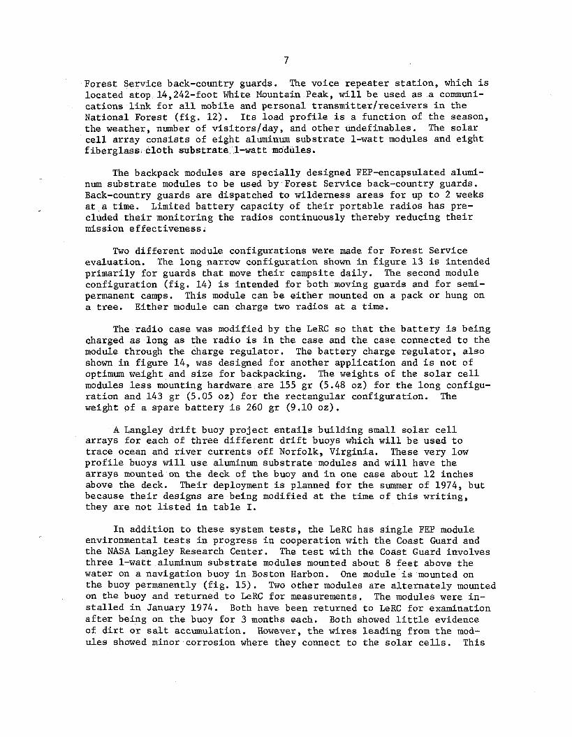
Fores t Serv ice back-country guards. The voice r epea t e r s t a t i o n , which i s loca t ed atop 14,242-foot White Mountain Peak, w i l l b e used a s a communi- ca t ions l i n k f o r a l l mobile and personal t r a n s m i t t e r f r e c e i v e r s i n t h e National Fores t ( f i g . 12 ) . Its load p r o f i l e i s a func t ion of t h e season, t h e weather, number of v i s i t o r s / d a y , and o t h e r undefinables . The s o l a r c e l l a r r a y c o n s i s t s of e i g h t aluminum s u b s t r a t e 1 - w a t t modules and e i g h t f i b e r g l a s s c l o t h s u b s t r a t e 1-watt modules.
The backpack modules a r e s p e c i a l l y designed FEP-encapsulated alumi- num s u b s t r a t e modules t o be used by Fores t Serv ice back-country guards. Back-country guards a r e dispatched t o wi lderness a r e a s f o r up t o 2 weeks a t a t i m e . Limited b a t t e r y capac i ty of t h e i r po r t ab l e r ad ios has pre- cluded t h e i r monitor ing the r ad ios cont inuously thereby reducing t h e i r mission e f f ec t iveness .
Two d i f f e r e n t module conf igura t ions were made f o r Fores t Serv ice eva lua t ion . The long narrow conf igura t ion shown i n f i g u r e 1 3 is intended p r imar i ly f o r guards t h a t move t h e i r campsite d a i l y . The second module conf igura t ion ( f i g . 14) i s intended f o r both moving guards and f o r semi- permanent camps. This module can be e i t h e r mounted on a pack o r hung on a t r e e . E i t h e r module can charge two r ad ios a t a time.
The r a d i o case was modified by t h e LeRC s o t h a t t h e b a t t e r y i s be ing charged a s long as t h e r a d i o i s i n t he case and t h e case connected t o t h e module through t h e charge r egu la to r . The b a t t e r y charge r e g u l a t o r , a l s o shown i n f i g u r e 14, was designed f o r another a p p l i c a t i o n and i s n o t of optimum weight and s i z e f o r backpacking. The weights of t h e s o l a r c e l l modules less mounting hardware a r e 155 g r (5.48 oz) f o r t h e long configu- r a t i o n and 143 g r (5.05 oz) f o r t h e rec tangular conf igura t ion . The weight of a spa re b a t t e r y i s 260 g r (9.10 oz ) .
A Langley d r i f t buoy p r o j e c t e n t a i l s b u i l d i n g smal l s o l a r c e l l a r r a y s f o r each of t h r e e d i f f e r e n t d r i f t buoys which w i l l b e used t o t r a c e ocean and r i v e r c u r r e n t s of f Norfolk, Vi rg in ia . These very low p r o f i l e buoys w i l l u se aluminum s u b s t r a t e modules and w i l l have t h e a r r a y s mounted on t h e deck of t h e buoy and i n one case about 1 2 inches above t h e deck. Their deployment i s planned f o r t he summer of 1974, b u t because t h e i r designs are being modified a t the time of t h i s w r i t i n g , they a r e n o t l i s t e d i n t a b l e I.
I n a d d i t i o n t o t hese system t e s t s , the LeRC has s i n g l e FEP module environmental t e s t s i n progress i n cooperat ion wi th t h e Coast Guard and t h e NASA Langley Research Center. The t e s t wi th t h e Coast Guard involves t h r e e 1-watt aluminum s u b s t r a t e modules mounted about 8 f e e t above t h e water on a naviga t ion buoy i n Boston Harbon. One module i s mounted on t h e buoy permanently ( f i g . 1 5 ) . Two o t h e r modules a r e a l t e r n a t e l y mounted on t h e buoy and r e tu rned t o LeRC f o r measurements. The modules were in - s t a l l e d i n January 1974. Both have been re turned t o LeRC f o r examination a f t e r being on t h e buoy f o r 3 months each. Both showed l i t t l e evidence of d i r t o r s a l t accumulation. However, t h e w i re s l ead ing from t h e mod- u l e s showed minor cor ros ion where they connect t o t h e s o l a r c e l l s . This

occurred because t h e wire connections t o t he s o l a r c e l l s , which are t h i c k e r than t h e FEP encapsulant , a r e occas iona l ly n o t completely covered by FEP. The problem has been remedied by l e a d wire connection r edes ign and a t h i c k e r FEP covering.
A t t h e NASA-Langley Research Center, an aluminum s u b s t r a t e module w a s mounted f l u s h i n t o t h e top of a smal l styrofoam buoy which was de- s igned so t h a t t h e s u r f a c e of t he module would be j u s t b a r e l y awash. The buoy was t e t h e r e d i n s e a water between two docks i n a boat s l i p a t Langley f o r two weeks a f t e r which i t w a s re turned t o Lewis f o r examina- t i o n . It showed some mechanical degradat ion and was covered wi th a b lo tchy l a y e r of d r i ed slime. This module was one which used s i l v e r mesh a s a c e l l in te rconnect ma te r i a l . During f a b r i c a t i o n of t he module, some of t h e ends of t he cu t mesh l e g s were bent upward and protruded through t h e FEP fol lowing laminat ion. Exposure t o s ea water induced cor ros ion of t h e mesh l e g s a t t h e s e p ro t rus ion s i t e s . The e f f e c t of t h e s a l t water continued down t h e mesh l e g , t o t h e c e l l con tac t s , and down t h e c e l l g r i d l i n e s . FEP delamination occurred i n t hese a r eas . This was t h e only delamination observed a f t e r t h i s s h o r t t e s t and p o i n t s out t h e importance of complete encapsula t ion of t h e a c t i v e module elements.
The module was then re turned t o Langley, mounted on t h e under s i d e of t h e buoy, and immersed under water f o r 4 weeks. A t t h e end of t h e 4 week per iod , ba rnac l e s and o t h e r forms of marine growth had formed on the module ( f i g . 1 6 ) . The cor ros ion noted fol lowing t h e f i r s t t e s t had continued t o cause FEP delamination. The void between t h e FEP and t h e c e l l , however, i s s o t h i n t h a t i n t e r f e r e n c e f r i n g e s a r e formed i n t h e de- laminated a rea .
Following r e t u r n of t h e module t o t h e LeRC and while i t w a s be ing photographed, s e v e r a l of t h e by then dry barnac les f e l l off t h e FEP sur - face . Following t h e as-received e l e c t r i c a l measurements, t h e module w a s washed under c l e a r cold water wi th a wet paper towel. A l l t h e remaining barnac les and marine growth washed o f f e a s i l y and the FEP s u r f a c e showed no t r a c e of t h e i r former presence.
E l e c t r i c a l measurements w e r e taken of both t h e Coast Guard buoy and Langley buoy modules a f t e r salt water exposures. The modules w e r e meas- ured i n an as-received condi t ion , and a f t e r a c l e a r water wash and r i n s e . The r e s u l t s of t hese measurements a r e shown i n t a b l e I V . Considering t h e d i f f e r e n c e s i n appearance i n t h e as-received condi t ion of t h e two modules, i t i s i n t e r e s t i n g t o no te t h a t t h e Langley buoy module does n o t show s i g - n i f i c a n t l y lower cu r r en t output . The meaning of t h e approximate 2.5 per- cent l o s s i n s h o r t - c i r c u i t cu r r en t f o r a l l t h e modules cannot be assessed a t this t i m e s i n c e t h i s d i f f e r e n c e i s nea r t h e l e v e l of r e p r o d u c i b i l i t y of s h o r t - c i r c u i t cu r r en t measurements. Longer exposures i n t h e ocean en- vironment a r e necessary t o e s t a b l i s h whether o r not e l e c t r i c a l degradat ion i s occurr ing .

CONCLUSIONS
The Solar Ce l l Branch a t t he NASA-LeRC has designed, b u i l t , and i n s t a l l e d s i x t e r r e s t r i a l s o l a r c e l l power systems us ing FEP-encapsulated s o l a r c e l l modules. An a d d i t i o n a l system i s being completed f o r i n s t a l - l a t i o n dur ing t h e summer of 1974. Resul t s from 7 months of ope ra t ion i n S t e r l i n g , V i rg in i a i n d i c a t e t h a t t he system i s meeting i t s e l e c t r i c a l de- s i g n requirements. No mechanical degradat ion has been repor ted a t t h e Vi rg in i a i n s t a l l a t i o n . I c e damaged t h e a r r a y on Mammoth Mountain, but d id not measurably degrade i t s e l e c t r i c a l performance. A roo f top t e s t a t t h e LeRC i s opera t ing s a t i s f a c t o r i l y , a l b e i t f o r on ly a s h o r t t ime. Re- s u l t s of marine environment t e s t s on s i n g l e modules have shown t h a t t h e e l e c t r i c a l l y a c t i v e elements of t h e module must be completely s ea l ed by the FEP. In te rconnect p ro t rus ions through the FEP o r c u t s i n t h e FEP which al low s a l t water access t o t he e l e c t r i c a l l y a c t i v e components in - duce FEP delamination. Based on t h e l imi t ed t e s t d a t a a v a i l a b l e , t he FEP-encapsulated s o l a r c e l l module appears we l l s u i t e d t o t e r r e s t r i a l app l i ca t ions .
REFERENCES
1. F o r e s t i e r i , A. F.; Broder, J . D.: Improvements i n S i l i c o n So la r C e l l Coverglass Assembly and Packaging Using FEP Teflon, NASA TM X-52875, J u l y 19 70 .
2 . Climatic Atlas of t he United S t a t e s , U.S. Department of Commerce, June 1968.
3 . Bernatowicz, D. T.: The NASA-Lewis T e r r e s t r i a l Photovol ta ics Program, Conference Record of t h e 10th Photovol ta ic S p e c i a l i s t s Conference, November 13-15, 1973.
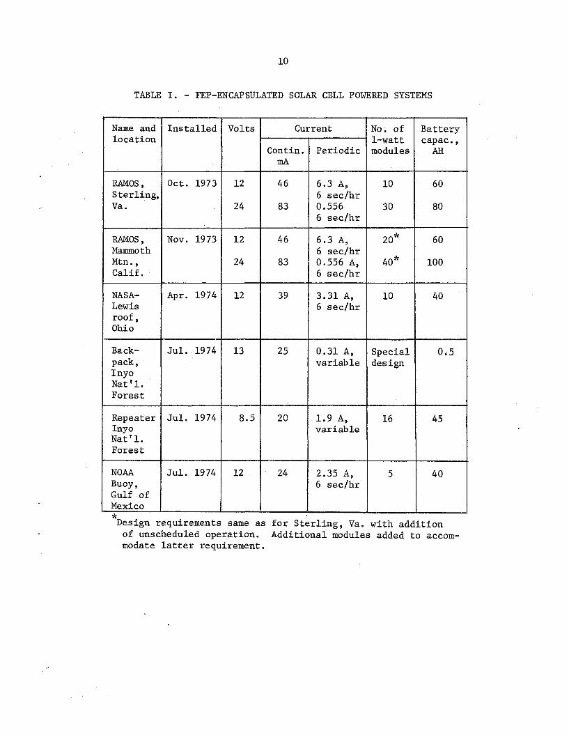
TABLE I. - FEP-ENCAPSULATED SOLAR CELL POWERED SYSTEMS

TABLE 11. - SHORT C I R C U I T CURRENT READINGS
OF RAMOS SYSTEM AT STERLING, V I R G I N I A
in dark clouds
overcast

TABLE 111. - SHORT CIRCUIT CURRENT READINGS OF RAMOS
SYSTEM ON MAMMOTH MOUNTAIN, CALIFORNIA
Sky condi t ions
Clear , very t h i n clouds Clear Clear (some i c e on a r r ay ) Overcast Overcast Clear Clear Clear
A i r mass zero s imula t ion
Date
Nov. 4 , 1973 Dec. 19, 1973 Jan. 24, 1974 Jan. 29, 1974 Feb. 14 , 1974 May 3 , 1974 J u l y 5, 1974 J u l y 6 , 1974
Shor t -c i rcu i t cu r ren t , mA
12-volt a r r ay
1610 1568 1100 320 600 465
1153 1155
1680
24-volt a r r ay
1556 1482 1100
320 600
1005 1165 1207
1680
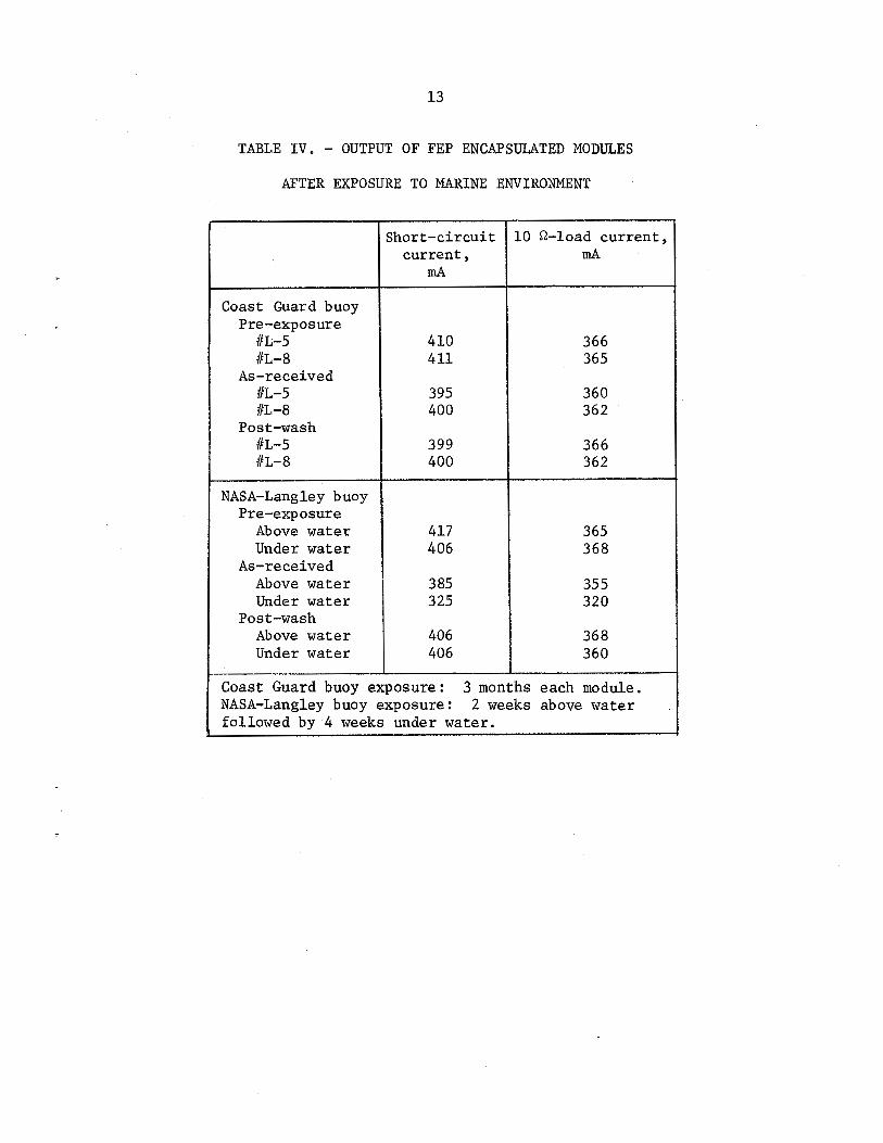
TABLE I V . - OUTPUT OF FEP ENCAPSULATED MODULES
AFTER EXPOSURE TO MARINE ENVIRONMENT
A s - r e c e i v e d
U n d e r w a t e r A s - r e c e i v e d
A b o v e w a t e r U n d e r w a t e r

Figure 1. - A 1-watt a luminum substrate FEP-encapsulated Figure 2. - A 1-watt fiber- Figure 3. - A 12-volt module of five module. glass cloth substrate 1-watt FEP-encapsulated modules.
FEP-encapsulated module.
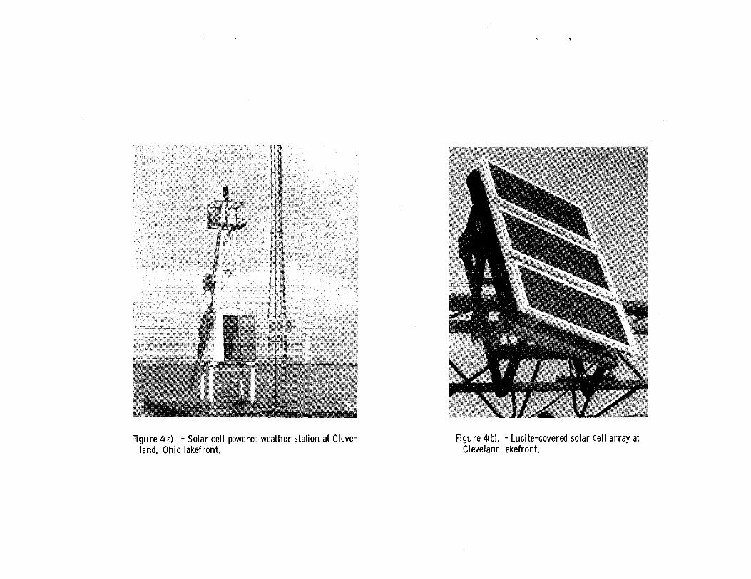
Figure 4a). - Solar cel l powered weather station at Cleve- land, Ohio lakefront.
Figure 4b) . - Lucite-covered solar ce l l ar ray at Cleveland lakefront.

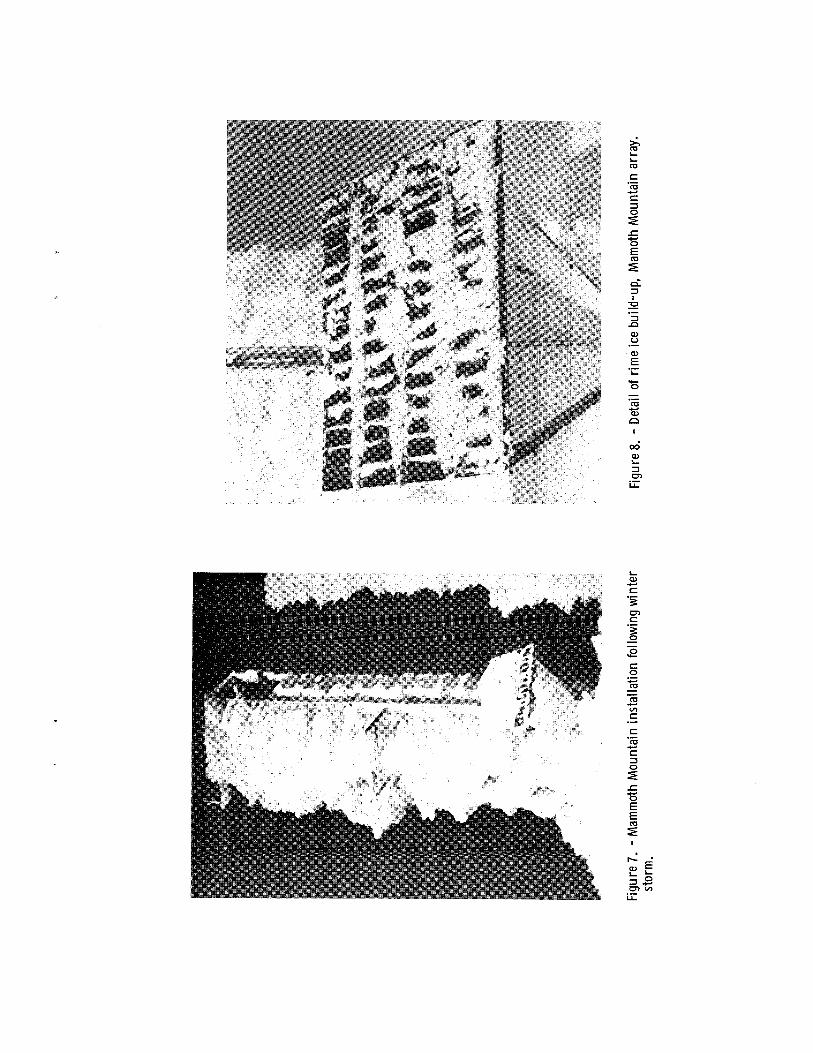

Figure 9(a). - Rime ice s t ruc tu ra l damage to Mammoth Mounta in array.
Figure 9(b). - Detail of r ime i ce damage to a module, Mammoth Mounta in array.

Figure 10. - Solar cel l power system experiment of NASA-LeRC labora- tory roof. Upper 12-volt module contains a luminum substrate mod- ules. Lower 12-volt module contains fiberglass cloth substrate mod- ules.

Figure l l (a ) . - NOAA experimental buoy wi th solar cell powered simulated RAMOS system.
Figure ll(b). - Solar cel l ar ray mounted on uppermost ra i l of NOAA experimental buoy.
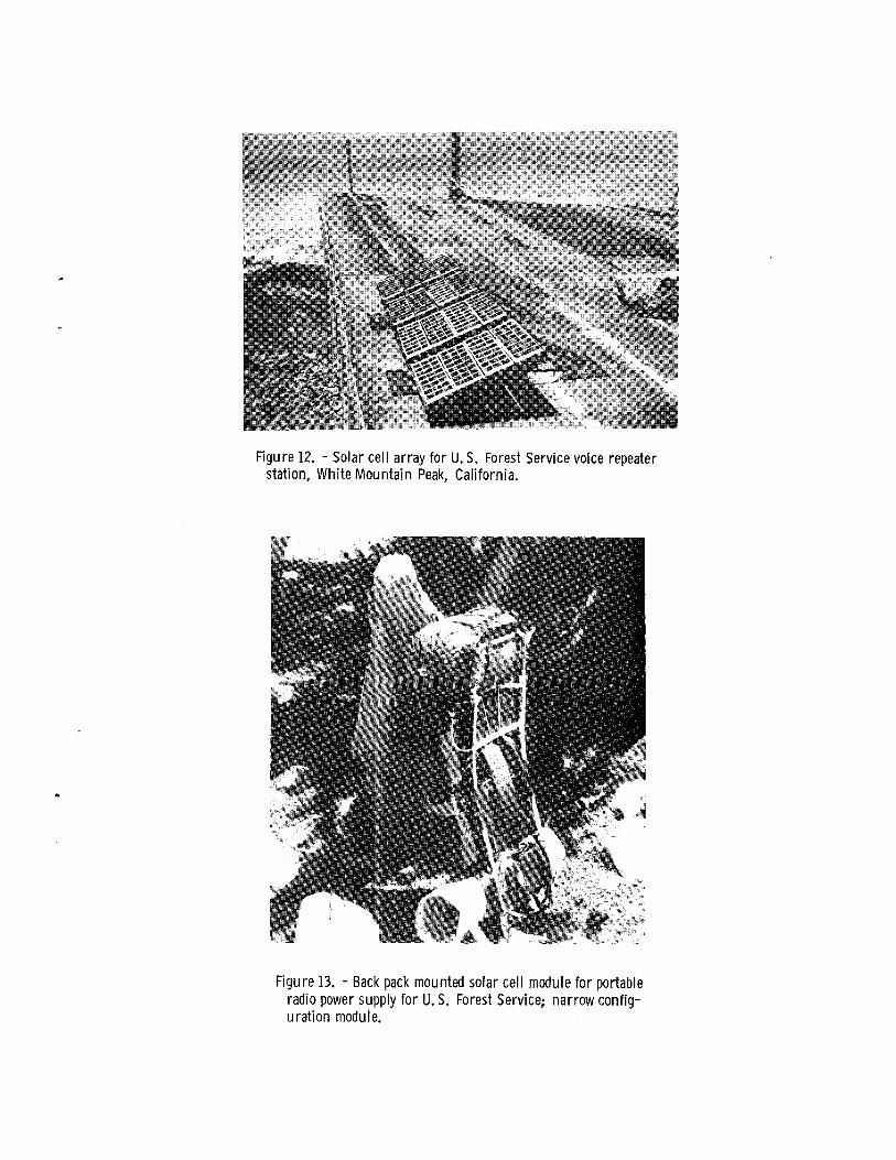
Figure 12. - Solar cell array for U. S. Forest Service voice repeater station, Whi teMounta in Peak, California.
Figure 13. - Back pack mounted solar cel l module for portable radio power supply for U. S. Forest Service; narrow config- urat ion module.
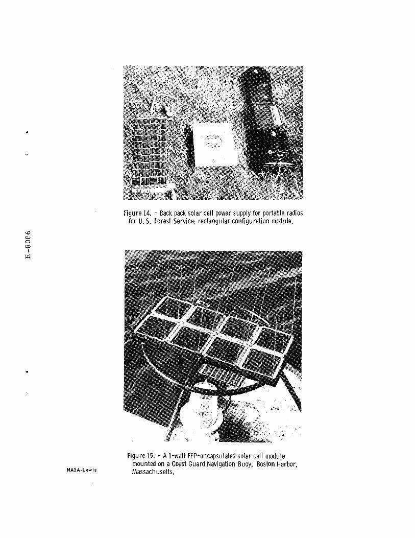
Figure 14. - Back pack solar cel l power supply for portable radios for U. S..Forest Service; rectangular conf igurat ion module.
Figure 15. - A 1-watt FEP-encapsulated solar cell module mounted on a Coast Guard Navigation Buoy, Boston Harbor, Massachusetts.