Embed Size (px)
Citation preview
8/12/2019 Termo_King_Magnum_manual.pdf
http://slidepdf.com/reader/full/termokingmagnummanualpdf 1/194
MAGNUMTK 51122-4-MM (Rev. 6, 02/06)
8/12/2019 Termo_King_Magnum_manual.pdf
http://slidepdf.com/reader/full/termokingmagnummanualpdf 2/194
This manual is published strictly for informational purposes. The information so provided should
not be considered as all-inclusive or covering all contingencies. Thermo King Corporation
should be consulted if further information is required.
Sale of product shown in this manual is subject to Thermo King’s terms and conditions.
This includes, but not limited to, the Thermo King Limited Express Warranty. Such terms
and conditions are available upon request. Thermo King’s warranty will not apply to any
equipment which has been “so repaired or altered outside the manufacturer’s plants as,
in the manufacturer’s judgment, to effect its stability.”
No warranties, express or implied, are made regarding the information,
recommendations, and descriptions contained herein. This includes warranties of
fitness for a particular purpose or merchantability, or warranties arising from course of
dealing or usage of trade The manufacturer is not responsible and will not be held liable
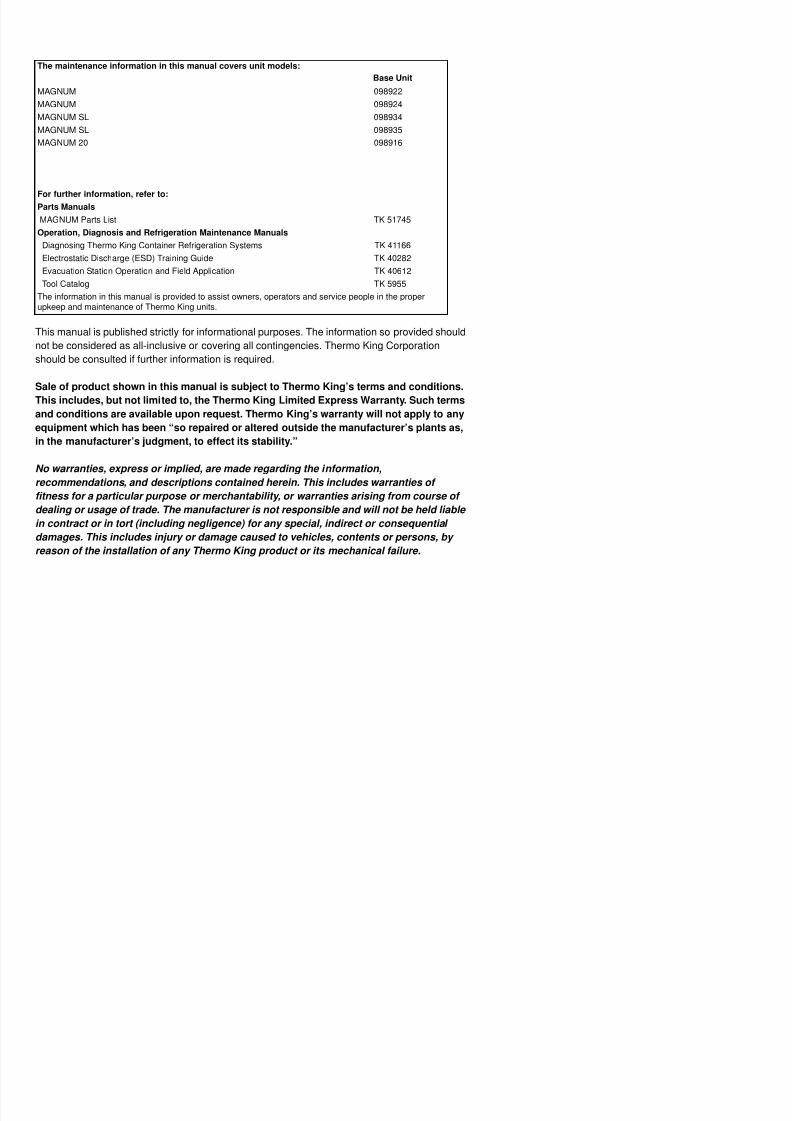
The maintenance information in this manual covers unit models:
Base Unit
MAGNUM 098922
MAGNUM 098924
MAGNUM SL 098934
MAGNUM SL 098935
MAGNUM 20 098916
For further information, refer to:
Parts Manuals
MAGNUM Parts List TK 51745
Operation, Diagnosis and Refrigeration Maintenance Manuals
Diagnosing Thermo King Container Refrigeration Systems TK 41166
Electrostatic Discharge (ESD) Training Guide TK 40282
Evacuation Station Operation and Field Application TK 40612
Tool Catalog TK 5955
The information in this manual is provided to assist owners, operators and service people in the properupkeep and maintenance of Thermo King units.
8/12/2019 Termo_King_Magnum_manual.pdf
http://slidepdf.com/reader/full/termokingmagnummanualpdf 3/194
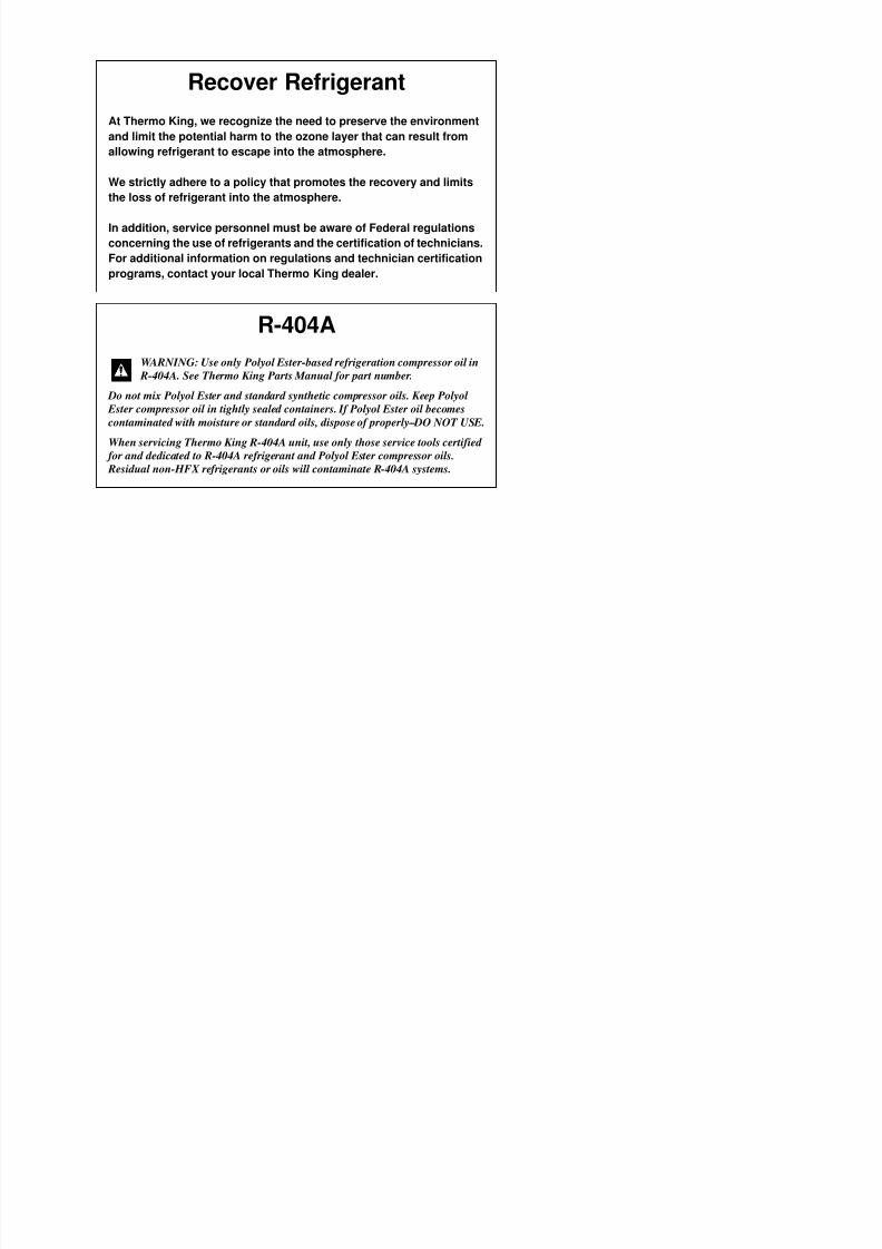
Recover Refrigerant
At Thermo King, we recognize the need to preserve the environment
and limit the potential harm to the ozone layer that can result from
allowing refrigerant to escape into the atmosphere.
We strictly adhere to a policy that promotes the recovery and limits
the loss of refrigerant into the atmosphere.
In addition, service personnel must be aware of Federal regulations
concerning the use of refrigerants and the certification of technicians.
For additional information on regulations and technician certification
programs, contact your local Thermo King dealer.
R-404A
WARNING: Use only Polyol Ester-based refrigeration compressor oil in
R-404A. See Thermo King Parts Manual for part number.
Do not mix Polyol Ester and standard synthetic compressor oils. Keep Polyol Ester compressor oil in tightly sealed containers. If Polyol Ester oil becomes
contaminated with moisture or standard oils, dispose of properly–DO NOT USE.
When servicing Thermo King R-404A unit, use only those service tools certified
for and dedicated to R-404A refrigerant and Polyol Ester compressor oils.
Residual non-HFX refrigerants or oils will contaminate R-404A systems.

8/12/2019 Termo_King_Magnum_manual.pdf
http://slidepdf.com/reader/full/termokingmagnummanualpdf 4/194
8/12/2019 Termo_King_Magnum_manual.pdf
http://slidepdf.com/reader/full/termokingmagnummanualpdf 5/194
Table of Contents
List Of Figures . . . . . . . . . . . . . . . . . . . . . . . . . . . . . . . . . . . . . . . . . . . . . . . . . . . . . . . . . . . . . . . . . . . . . . . . . . 11
Safety Instructions . . . . . . . . . . . . . . . . . . . . . . . . . . . . . . . . . . . . . . . . . . . . . . . . . . . . . . . . . . . . . . . . . . . . . . 13
General Precautions . . . . . . . . . . . . . . . . . . . . . . . . . . . . . . . . . . . . . . . . . . . . . . . . . . . . . . . . . . . . . . . . . . . . . . 13Refrigerant Oil Precautions . . . . . . . . . . . . . . . . . . . . . . . . . . . . . . . . . . . . . . . . . . . . . . . . . . . . . . . . . . . . . . . . . 13Electrical Precautions . . . . . . . . . . . . . . . . . . . . . . . . . . . . . . . . . . . . . . . . . . . . . . . . . . . . . . . . . . . . . . . . . . . . . 13
Precautions . . . . . . . . . . . . . . . . . . . . . . . . . . . . . . . . . . . . . . . . . . . . . . . . . . . . . . . . . . . . . . . . . . . . . . . . . . 13First Aid . . . . . . . . . . . . . . . . . . . . . . . . . . . . . . . . . . . . . . . . . . . . . . . . . . . . . . . . . . . . . . . . . . . . . . . . . . . . 14Low Voltage . . . . . . . . . . . . . . . . . . . . . . . . . . . . . . . . . . . . . . . . . . . . . . . . . . . . . . . . . . . . . . . . . . . . . . . . . 14
Electrostatic Discharge Precautions . . . . . . . . . . . . . . . . . . . . . . . . . . . . . . . . . . . . . . . . . . . . . . . . . . . . . . . . . . 14Electrostatic Discharge and the Controller . . . . . . . . . . . . . . . . . . . . . . . . . . . . . . . . . . . . . . . . . . . . . . . . . . 14
Welding of Units or Containers . . . . . . . . . . . . . . . . . . . . . . . . . . . . . . . . . . . . . . . . . . . . . . . . . . . . . . . . . . . 15Removing Refrigerant Properly . . . . . . . . . . . . . . . . . . . . . . . . . . . . . . . . . . . . . . . . . . . . . . . . . . . . . . . . . . . . . . 15Identifying Unit Safety and Warning Decals . . . . . . . . . . . . . . . . . . . . . . . . . . . . . . . . . . . . . . . . . . . . . . . . . . . . 16Locating Serial Numbers . . . . . . . . . . . . . . . . . . . . . . . . . . . . . . . . . . . . . . . . . . . . . . . . . . . . . . . . . . . . . . . . . . . 16
Service Guide . . . . . . . . . . . . . . . . . . . . . . . . . . . . . . . . . . . . . . . . . . . . . . . . . . . . . . . . . . . . . . . . . . . . . . . . . . 17
Specifications . . . . . . . . . . . . . . . . . . . . . . . . . . . . . . . . . . . . . . . . . . . . . . . . . . . . . . . . . . . . . . . . . . . . . . . . . . 19System Net Cooling Capacity— Full Cool . . . . . . . . . . . . . . . . . . . . . . . . . . . . . . . . . . . . . . . . . . . . . . . . . . . . . . 19Evaporator Airflow Specifications . . . . . . . . . . . . . . . . . . . . . . . . . . . . . . . . . . . . . . . . . . . . . . . . . . . . . . . . . . . . 20Electrical System Specifications . . . . . . . . . . . . . . . . . . . . . . . . . . . . . . . . . . . . . . . . . . . . . . . . . . . . . . . . . . . . . 21Refrigeration System Specifications . . . . . . . . . . . . . . . . . . . . . . . . . . . . . . . . . . . . . . . . . . . . . . . . . . . . . . . . . . 22Normal R-404A System Operating Pressures (Scroll Compressor) . . . . . . . . . . . . . . . . . . . . . . . . . . . . . . . . . . 23MP-3000a Controller Specifications . . . . . . . . . . . . . . . . . . . . . . . . . . . . . . . . . . . . . . . . . . . . . . . . . . . . . . . . . . 24Physical Specifications . . . . . . . . . . . . . . . . . . . . . . . . . . . . . . . . . . . . . . . . . . . . . . . . . . . . . . . . . . . . . . . . . . . . 26Metric Hardware Torque Charts . . . . . . . . . . . . . . . . . . . . . . . . . . . . . . . . . . . . . . . . . . . . . . . . . . . . . . . . . . . . . 28
Unit Description, Features & Options . . . . . . . . . . . . . . . . . . . . . . . . . . . . . . . . . . . . . . . . . . . . . . . . . . . . . . . 29Introduction . . . . . . . . . . . . . . . . . . . . . . . . . . . . . . . . . . . . . . . . . . . . . . . . . . . . . . . . . . . . . . . . . . . . . . . . . . . . . 29
General Description . . . . . . . . . . . . . . . . . . . . . . . . . . . . . . . . . . . . . . . . . . . . . . . . . . . . . . . . . . . . . . . . . . . 29
Scroll Compressor . . . . . . . . . . . . . . . . . . . . . . . . . . . . . . . . . . . . . . . . . . . . . . . . . . . . . . . . . . . . . . . . . . . . . . . 30MP-3000a Controller . . . . . . . . . . . . . . . . . . . . . . . . . . . . . . . . . . . . . . . . . . . . . . . . . . . . . . . . . . . . . . . . . . . . . . 30Compressor Digital Control Valve . . . . . . . . . . . . . . . . . . . . . . . . . . . . . . . . . . . . . . . . . . . . . . . . . . . . . . . . . . . . 30Economizer Heat Exchange System . . . . . . . . . . . . . . . . . . . . . . . . . . . . . . . . . . . . . . . . . . . . . . . . . . . . . . . . . 31Temperature Sensors . . . . . . . . . . . . . . . . . . . . . . . . . . . . . . . . . . . . . . . . . . . . . . . . . . . . . . . . . . . . . . . . . . . . . 31Fresh Air Exchange System . . . . . . . . . . . . . . . . . . . . . . . . . . . . . . . . . . . . . . . . . . . . . . . . . . . . . . . . . . . . . . . . 31Fresh Air Exchange Recorder (Optional) . . . . . . . . . . . . . . . . . . . . . . . . . . . . . . . . . . . . . . . . . . . . . . . . . . . . . . 31Receiver Tank Sight Glass . . . . . . . . . . . . . . . . . . . . . . . . . . . . . . . . . . . . . . . . . . . . . . . . . . . . . . . . . . . . . . . . 32Evaporator Fans . . . . . . . . . . . . . . . . . . . . . . . . . . . . . . . . . . . . . . . . . . . . . . . . . . . . . . . . . . . . . . . . . . . . . . . . . 32Condenser Fan Control . . . . . . . . . . . . . . . . . . . . . . . . . . . . . . . . . . . . . . . . . . . . . . . . . . . . . . . . . . . . . . . . . . . . 32Unit Options . . . . . . . . . . . . . . . . . . . . . . . . . . . . . . . . . . . . . . . . . . . . . . . . . . . . . . . . . . . . . . . . . . . . . . . . . . . . 33
Recording Thermometer (Optional) . . . . . . . . . . . . . . . . . . . . . . . . . . . . . . . . . . . . . . . . . . . . . . . . . . . . . . . 33Remote Monitoring Receptacle Option (4-Pin) (Optional) . . . . . . . . . . . . . . . . . . . . . . . . . . . . . . . . . . . . . . 33Remote Monitoring Modem (RMM) (Optional) . . . . . . . . . . . . . . . . . . . . . . . . . . . . . . . . . . . . . . . . . . . . . . . 33Suction and Discharge Pressure Sensors (Optional) . . . . . . . . . . . . . . . . . . . . . . . . . . . . . . . . . . . . . . . . . . 33
8/12/2019 Termo_King_Magnum_manual.pdf
http://slidepdf.com/reader/full/termokingmagnummanualpdf 6/194
Table of Contents
Navigating the Controller Operating Menu . . . . . . . . . . . . . . . . . . . . . . . . . . . . . . . . . . . . . . . . . . . . . . . . . . . 45Navigating the Controller Operating Menu . . . . . . . . . . . . . . . . . . . . . . . . . . . . . . . . . . . . . . . . . . . . . . . . . . . . . 45Menu Scrolling Keys . . . . . . . . . . . . . . . . . . . . . . . . . . . . . . . . . . . . . . . . . . . . . . . . . . . . . . . . . . . . . . . . . . . . . . 45
Operating Instructions . . . . . . . . . . . . . . . . . . . . . . . . . . . . . . . . . . . . . . . . . . . . . . . . . . . . . . . . . . . . . . . . . . . 47Unit On/Off Switch . . . . . . . . . . . . . . . . . . . . . . . . . . . . . . . . . . . . . . . . . . . . . . . . . . . . . . . . . . . . . . . . . . . . . . . . 47Sequence Of Operation . . . . . . . . . . . . . . . . . . . . . . . . . . . . . . . . . . . . . . . . . . . . . . . . . . . . . . . . . . . . . . . . . . . . 47
Unit Start-up . . . . . . . . . . . . . . . . . . . . . . . . . . . . . . . . . . . . . . . . . . . . . . . . . . . . . . . . . . . . . . . . . . . . . . . . . 47Controller Input and Output Signals . . . . . . . . . . . . . . . . . . . . . . . . . . . . . . . . . . . . . . . . . . . . . . . . . . . . . . . . . . 47Change the Setpoint . . . . . . . . . . . . . . . . . . . . . . . . . . . . . . . . . . . . . . . . . . . . . . . . . . . . . . . . . . . . . . . . . . . . . . 48Initiating a Manual Defrost . . . . . . . . . . . . . . . . . . . . . . . . . . . . . . . . . . . . . . . . . . . . . . . . . . . . . . . . . . . . . . . . . . 48Display Alternate Controlling (Supply or Return) Air Sensor Temperature . . . . . . . . . . . . . . . . . . . . . . . . . . . . . 48Display Alternate Fahrenheit (F) or Celsius (C) Temperatures . . . . . . . . . . . . . . . . . . . . . . . . . . . . . . . . . . . . . .49
Setpoint Menu . . . . . . . . . . . . . . . . . . . . . . . . . . . . . . . . . . . . . . . . . . . . . . . . . . . . . . . . . . . . . . . . . . . . . . . . . . . 50Change the Setpoint Temperature . . . . . . . . . . . . . . . . . . . . . . . . . . . . . . . . . . . . . . . . . . . . . . . . . . . . . . . . 51Change Condenser Fan Mode . . . . . . . . . . . . . . . . . . . . . . . . . . . . . . . . . . . . . . . . . . . . . . . . . . . . . . . . . . . 51Change the Bulb Mode Setting . . . . . . . . . . . . . . . . . . . . . . . . . . . . . . . . . . . . . . . . . . . . . . . . . . . . . . . . . . . 51Change the Economy Mode Setting . . . . . . . . . . . . . . . . . . . . . . . . . . . . . . . . . . . . . . . . . . . . . . . . . . . . . . . 52Change the Humidity Mode Setting . . . . . . . . . . . . . . . . . . . . . . . . . . . . . . . . . . . . . . . . . . . . . . . . . . . . . . . 52Change the Humidity Setpoint . . . . . . . . . . . . . . . . . . . . . . . . . . . . . . . . . . . . . . . . . . . . . . . . . . . . . . . . . . . 53Changing the Advanced Fresh Air Management (AFAM) or
Advanced Fresh Air Management Plus (AFAM+) Setting . . . . . . . . . . . . . . . . . . . . . . . . . . . . . . . . . . .53
Alarms Menu . . . . . . . . . . . . . . . . . . . . . . . . . . . . . . . . . . . . . . . . . . . . . . . . . . . . . . . . . . . . . . . . . . . . . . . . . . . . 54Alarm Types . . . . . . . . . . . . . . . . . . . . . . . . . . . . . . . . . . . . . . . . . . . . . . . . . . . . . . . . . . . . . . . . . . . . . . . . . 54
Alarm Code States . . . . . . . . . . . . . . . . . . . . . . . . . . . . . . . . . . . . . . . . . . . . . . . . . . . . . . . . . . . . . . . . . . . . . . . 54View the Alarm List Menu . . . . . . . . . . . . . . . . . . . . . . . . . . . . . . . . . . . . . . . . . . . . . . . . . . . . . . . . . . . . . . . 54Alarm List . . . . . . . . . . . . . . . . . . . . . . . . . . . . . . . . . . . . . . . . . . . . . . . . . . . . . . . . . . . . . . . . . . . . . . . . . . . 56
Data Menu . . . . . . . . . . . . . . . . . . . . . . . . . . . . . . . . . . . . . . . . . . . . . . . . . . . . . . . . . . . . . . . . . . . . . . . . . . . . . . 57Viewing the Data Menu . . . . . . . . . . . . . . . . . . . . . . . . . . . . . . . . . . . . . . . . . . . . . . . . . . . . . . . . . . . . . . . . . 57
RMM State Menu . . . . . . . . . . . . . . . . . . . . . . . . . . . . . . . . . . . . . . . . . . . . . . . . . . . . . . . . . . . . . . . . . . . . . . . . . 58
Viewing the RMM State Screen . . . . . . . . . . . . . . . . . . . . . . . . . . . . . . . . . . . . . . . . . . . . . . . . . . . . . . . . . . 58Datalogger Menu . . . . . . . . . . . . . . . . . . . . . . . . . . . . . . . . . . . . . . . . . . . . . . . . . . . . . . . . . . . . . . . . . . . . . . . . . 59Viewing the Datalogger Menu . . . . . . . . . . . . . . . . . . . . . . . . . . . . . . . . . . . . . . . . . . . . . . . . . . . . . . . . . . . . 59Inspect Temp Log . . . . . . . . . . . . . . . . . . . . . . . . . . . . . . . . . . . . . . . . . . . . . . . . . . . . . . . . . . . . . . . . . . . . . 59Inspect Event Log . . . . . . . . . . . . . . . . . . . . . . . . . . . . . . . . . . . . . . . . . . . . . . . . . . . . . . . . . . . . . . . . . . . . . 60Calibrate USDA Probe (Optional) . . . . . . . . . . . . . . . . . . . . . . . . . . . . . . . . . . . . . . . . . . . . . . . . . . . . . . . . . 60Set Trip Start . . . . . . . . . . . . . . . . . . . . . . . . . . . . . . . . . . . . . . . . . . . . . . . . . . . . . . . . . . . . . . . . . . . . . . . . . 62Set Log Time . . . . . . . . . . . . . . . . . . . . . . . . . . . . . . . . . . . . . . . . . . . . . . . . . . . . . . . . . . . . . . . . . . . . . . . . . 63Inspect Event Log . . . . . . . . . . . . . . . . . . . . . . . . . . . . . . . . . . . . . . . . . . . . . . . . . . . . . . . . . . . . . . . . . . . . . 64
Configuration Menu . . . . . . . . . . . . . . . . . . . . . . . . . . . . . . . . . . . . . . . . . . . . . . . . . . . . . . . . . . . . . . . . . . . . . . . 65Viewing or Setting Functions . . . . . . . . . . . . . . . . . . . . . . . . . . . . . . . . . . . . . . . . . . . . . . . . . . . . . . . . . . . . 65
Misc. Functions Menu . . . . . . . . . . . . . . . . . . . . . . . . . . . . . . . . . . . . . . . . . . . . . . . . . . . . . . . . . . . . . . . . . . . . . 67View Misc. Functions Menu . . . . . . . . . . . . . . . . . . . . . . . . . . . . . . . . . . . . . . . . . . . . . . . . . . . . . . . . . . . . . 67Set Date and Time . . . . . . . . . . . . . . . . . . . . . . . . . . . . . . . . . . . . . . . . . . . . . . . . . . . . . . . . . . . . . . . . . . . . 68View or Set Run Time . . . . . . . . . . . . . . . . . . . . . . . . . . . . . . . . . . . . . . . . . . . . . . . . . . . . . . . . . . . . . . . . . . 68Set Cargo Data 69
8/12/2019 Termo_King_Magnum_manual.pdf
http://slidepdf.com/reader/full/termokingmagnummanualpdf 7/194
Table of Contents
Operating Instructions (continued)Starting the AFAM System . . . . . . . . . . . . . . . . . . . . . . . . . . . . . . . . . . . . . . . . . . . . . . . . . . . . . . . . . . . . . . . . . 87
Change the AFAM Delay . . . . . . . . . . . . . . . . . . . . . . . . . . . . . . . . . . . . . . . . . . . . . . . . . . . . . . . . . . . . . . . 87Change the AFAM Rate . . . . . . . . . . . . . . . . . . . . . . . . . . . . . . . . . . . . . . . . . . . . . . . . . . . . . . . . . . . . . . . . 88
Advanced Fresh Air Management Plus (AFAM+) System . . . . . . . . . . . . . . . . . . . . . . . . . . . . . . . . . . . . . . . . . 89Set AFAM+ System Values . . . . . . . . . . . . . . . . . . . . . . . . . . . . . . . . . . . . . . . . . . . . . . . . . . . . . . . . . . . . . 89Change the AFAM Delay . . . . . . . . . . . . . . . . . . . . . . . . . . . . . . . . . . . . . . . . . . . . . . . . . . . . . . . . . . . . . . . 89Change the CO2 Minimum and Maximum Setting . . . . . . . . . . . . . . . . . . . . . . . . . . . . . . . . . . . . . . . . . . . . 90OPTI-SET . . . . . . . . . . . . . . . . . . . . . . . . . . . . . . . . . . . . . . . . . . . . . . . . . . . . . . . . . . . . . . . . . . . . . . . . . . . 91Setting the AFAM+ or AFAM System . . . . . . . . . . . . . . . . . . . . . . . . . . . . . . . . . . . . . . . . . . . . . . . . . . . . . . 91Changing the AFAM+ Settings Using ‘OPTISET’ (sets ‘DEMAND’ Mode) . . . . . . . . . . . . . . . . . . . . . . . . . . 92Modify Optiset Product Settings in ‘DEMAND’ . . . . . . . . . . . . . . . . . . . . . . . . . . . . . . . . . . . . . . . . . . . . . . . 92
Changing the AFAM Mode to ‘DEMAND’ . . . . . . . . . . . . . . . . . . . . . . . . . . . . . . . . . . . . . . . . . . . . . . . . . . . 92Changing the AFAM Mode to ‘UNITS’ . . . . . . . . . . . . . . . . . . . . . . . . . . . . . . . . . . . . . . . . . . . . . . . . . . . . . 93Changing the AFAM Mode to ‘MANUAL’ . . . . . . . . . . . . . . . . . . . . . . . . . . . . . . . . . . . . . . . . . . . . . . . . . . . 93Testing AFAM+ / AFAM System . . . . . . . . . . . . . . . . . . . . . . . . . . . . . . . . . . . . . . . . . . . . . . . . . . . . . . . . . . 94AFAM+ Option Alarm Codes (see manual for further descriptions) –
Software versions 04100100 and above . . . . . . . . . . . . . . . . . . . . . . . . . . . . . . . . . . . . . . . . . . . . . . . . 94Alarm Codes and Actions / Data Menu Display . . . . . . . . . . . . . . . . . . . . . . . . . . . . . . . . . . . . . . . . . . . . . . 96
Vent Door Calibration and Linkage Adjustment . . . . . . . . . . . . . . . . . . . . . . . . . . . . . . . . . . . . . . . . . . . . . . . . . 98Vent Door Calibration . . . . . . . . . . . . . . . . . . . . . . . . . . . . . . . . . . . . . . . . . . . . . . . . . . . . . . . . . . . . . . . . . . 98
Linkage / Door Adjustment . . . . . . . . . . . . . . . . . . . . . . . . . . . . . . . . . . . . . . . . . . . . . . . . . . . . . . . . . . . . . . 98Fresh Air Exchange Recorder (Optional) . . . . . . . . . . . . . . . . . . . . . . . . . . . . . . . . . . . . . . . . . . . . . . . . . . . . . 100Electronic Chart Recorder for MP3000a Controllers . . . . . . . . . . . . . . . . . . . . . . . . . . . . . . . . . . . . . . . . . . . . . 101
Recorder Installation . . . . . . . . . . . . . . . . . . . . . . . . . . . . . . . . . . . . . . . . . . . . . . . . . . . . . . . . . . . . . . . . . . 101Recorder Setup . . . . . . . . . . . . . . . . . . . . . . . . . . . . . . . . . . . . . . . . . . . . . . . . . . . . . . . . . . . . . . . . . . . . . 102Main Menu . . . . . . . . . . . . . . . . . . . . . . . . . . . . . . . . . . . . . . . . . . . . . . . . . . . . . . . . . . . . . . . . . . . . . . . . . 102Configuration . . . . . . . . . . . . . . . . . . . . . . . . . . . . . . . . . . . . . . . . . . . . . . . . . . . . . . . . . . . . . . . . . . . . . . . 102
Operating Theory . . . . . . . . . . . . . . . . . . . . . . . . . . . . . . . . . . . . . . . . . . . . . . . . . . . . . . . . . . . . . . . . . . . . . . 105
Chill Loads: (Setpoint at -9.9 C [14.1 F] and Above) . . . . . . . . . . . . . . . . . . . . . . . . . . . . . . . . . . . . . . . . . 105Frozen Loads: (Setpoint at -10 C [14 F] and Below) . . . . . . . . . . . . . . . . . . . . . . . . . . . . . . . . . . . . . . . . . 105Compressor Vapor Injection . . . . . . . . . . . . . . . . . . . . . . . . . . . . . . . . . . . . . . . . . . . . . . . . . . . . . . . . . . . . 105High Temperature Protection . . . . . . . . . . . . . . . . . . . . . . . . . . . . . . . . . . . . . . . . . . . . . . . . . . . . . . . . . . . 106Power Limit Mode . . . . . . . . . . . . . . . . . . . . . . . . . . . . . . . . . . . . . . . . . . . . . . . . . . . . . . . . . . . . . . . . . . . . 106Evaporator Fan Control . . . . . . . . . . . . . . . . . . . . . . . . . . . . . . . . . . . . . . . . . . . . . . . . . . . . . . . . . . . . . . . 106Economy Mode Operation . . . . . . . . . . . . . . . . . . . . . . . . . . . . . . . . . . . . . . . . . . . . . . . . . . . . . . . . . . . . . 106Condenser Fan Control . . . . . . . . . . . . . . . . . . . . . . . . . . . . . . . . . . . . . . . . . . . . . . . . . . . . . . . . . . . . . . . 107Probe Test . . . . . . . . . . . . . . . . . . . . . . . . . . . . . . . . . . . . . . . . . . . . . . . . . . . . . . . . . . . . . . . . . . . . . . . . . 107
Bulb Mode . . . . . . . . . . . . . . . . . . . . . . . . . . . . . . . . . . . . . . . . . . . . . . . . . . . . . . . . . . . . . . . . . . . . . . . . . 107Dehumidify Mode . . . . . . . . . . . . . . . . . . . . . . . . . . . . . . . . . . . . . . . . . . . . . . . . . . . . . . . . . . . . . . . . . . . . 107Continuous Temperature Control Operation . . . . . . . . . . . . . . . . . . . . . . . . . . . . . . . . . . . . . . . . . . . . . . . 108Frozen Loads (Controller Setpoint at -10 C [14 F] and Below): . . . . . . . . . . . . . . . . . . . . . . . . . . . . . . . . . 110
Compressor Digital Control Valve . . . . . . . . . . . . . . . . . . . . . . . . . . . . . . . . . . . . . . . . . . . . . . . . . . . . . . . . . . . 112Economizer System . . . . . . . . . . . . . . . . . . . . . . . . . . . . . . . . . . . . . . . . . . . . . . . . . . . . . . . . . . . . . . . . . . . . . 113Data Recording and Downloading Data 113
8/12/2019 Termo_King_Magnum_manual.pdf
http://slidepdf.com/reader/full/termokingmagnummanualpdf 8/194
Table of Contents
Electrical Maintenance (continued)High Pressure Cutout Manifold . . . . . . . . . . . . . . . . . . . . . . . . . . . . . . . . . . . . . . . . . . . . . . . . . . . . . . . . . . . . . 119
High Pressure Cutout Switch Removal . . . . . . . . . . . . . . . . . . . . . . . . . . . . . . . . . . . . . . . . . . . . . . . . . . . . 120High Pressure Cutout Switch Installation . . . . . . . . . . . . . . . . . . . . . . . . . . . . . . . . . . . . . . . . . . . . . . . . . . 120
Low Pressure Cutout Switch . . . . . . . . . . . . . . . . . . . . . . . . . . . . . . . . . . . . . . . . . . . . . . . . . . . . . . . . . . . . . . . 121Low Pressure Cutout Switch Removal . . . . . . . . . . . . . . . . . . . . . . . . . . . . . . . . . . . . . . . . . . . . . . . . . . . . 121Low Pressure Cutout Switch Installation . . . . . . . . . . . . . . . . . . . . . . . . . . . . . . . . . . . . . . . . . . . . . . . . . . . 122
Discharge and Low Pressure Sensors (Optional) . . . . . . . . . . . . . . . . . . . . . . . . . . . . . . . . . . . . . . . . . . . . . . . 122Discharge and Low Pressure Sensors Removal . . . . . . . . . . . . . . . . . . . . . . . . . . . . . . . . . . . . . . . . . . . . . 122Discharge and Low Pressure Sensor Installation . . . . . . . . . . . . . . . . . . . . . . . . . . . . . . . . . . . . . . . . . . . . 122
Condenser Fan and Evaporator Fan Rotation . . . . . . . . . . . . . . . . . . . . . . . . . . . . . . . . . . . . . . . . . . . . . . . . . . 123Check Condenser Fan Rotation . . . . . . . . . . . . . . . . . . . . . . . . . . . . . . . . . . . . . . . . . . . . . . . . . . . . . . . . . 123
Check Evaporator Fan Rotation . . . . . . . . . . . . . . . . . . . . . . . . . . . . . . . . . . . . . . . . . . . . . . . . . . . . . . . . . 123Reversing Power Phase on MAGNUM Units . . . . . . . . . . . . . . . . . . . . . . . . . . . . . . . . . . . . . . . . . . . . . . . . . .124Electric Heaters Malfunction . . . . . . . . . . . . . . . . . . . . . . . . . . . . . . . . . . . . . . . . . . . . . . . . . . . . . . . . . . . . . . . 124Compressor Discharge Gas Temperature Sensor . . . . . . . . . . . . . . . . . . . . . . . . . . . . . . . . . . . . . . . . . . . . . .125
Compressor Discharge Temperature Sensor Replacement . . . . . . . . . . . . . . . . . . . . . . . . . . . . . . . . . . . . 125Temperature Sensors . . . . . . . . . . . . . . . . . . . . . . . . . . . . . . . . . . . . . . . . . . . . . . . . . . . . . . . . . . . . . . . . . . . . 126
Installing Temperature Sensors . . . . . . . . . . . . . . . . . . . . . . . . . . . . . . . . . . . . . . . . . . . . . . . . . . . . . . . . . 126Testing the Sensors . . . . . . . . . . . . . . . . . . . . . . . . . . . . . . . . . . . . . . . . . . . . . . . . . . . . . . . . . . . . . . . . . . . . . . 127
Resistance Values for Temperature Sensors . . . . . . . . . . . . . . . . . . . . . . . . . . . . . . . . . . . . . . . . . . . . . . . 128
Refrigeration Maintenance . . . . . . . . . . . . . . . . . . . . . . . . . . . . . . . . . . . . . . . . . . . . . . . . . . . . . . . . . . . . . . . 129Introduction . . . . . . . . . . . . . . . . . . . . . . . . . . . . . . . . . . . . . . . . . . . . . . . . . . . . . . . . . . . . . . . . . . . . . . . . . . . . 129Use the Correct Tools . . . . . . . . . . . . . . . . . . . . . . . . . . . . . . . . . . . . . . . . . . . . . . . . . . . . . . . . . . . . . . . . . . . . 129Use the Correct Vacuum Pump . . . . . . . . . . . . . . . . . . . . . . . . . . . . . . . . . . . . . . . . . . . . . . . . . . . . . . . . . . . . . 129Use Filters and Cartridges . . . . . . . . . . . . . . . . . . . . . . . . . . . . . . . . . . . . . . . . . . . . . . . . . . . . . . . . . . . . . . . . . 129Use the Correct Refrigerant Recovery Equipment . . . . . . . . . . . . . . . . . . . . . . . . . . . . . . . . . . . . . . . . . . . . . .129Detecting Leaks . . . . . . . . . . . . . . . . . . . . . . . . . . . . . . . . . . . . . . . . . . . . . . . . . . . . . . . . . . . . . . . . . . . . . . . . . 129Locating Special Service Fittings . . . . . . . . . . . . . . . . . . . . . . . . . . . . . . . . . . . . . . . . . . . . . . . . . . . . . . . . . . . . 129Perform an Oil Acid Test . . . . . . . . . . . . . . . . . . . . . . . . . . . . . . . . . . . . . . . . . . . . . . . . . . . . . . . . . . . . . . . . . . 130Isolate the Compressor . . . . . . . . . . . . . . . . . . . . . . . . . . . . . . . . . . . . . . . . . . . . . . . . . . . . . . . . . . . . . . . . . . . 130Working with a Gauge Manifold . . . . . . . . . . . . . . . . . . . . . . . . . . . . . . . . . . . . . . . . . . . . . . . . . . . . . . . . . . . . . 130
Using a New Gauge Manifold Set . . . . . . . . . . . . . . . . . . . . . . . . . . . . . . . . . . . . . . . . . . . . . . . . . . . . . . . . 130Gauge Manifold Valve Positions . . . . . . . . . . . . . . . . . . . . . . . . . . . . . . . . . . . . . . . . . . . . . . . . . . . . . . . . . 130
Gauge Manifold Set Installation & Removal . . . . . . . . . . . . . . . . . . . . . . . . . . . . . . . . . . . . . . . . . . . . . . . . . . . 131Gauge Manifold Set Installation . . . . . . . . . . . . . . . . . . . . . . . . . . . . . . . . . . . . . . . . . . . . . . . . . . . . . . . . . 131Removing the Gauge Manifold Set . . . . . . . . . . . . . . . . . . . . . . . . . . . . . . . . . . . . . . . . . . . . . . . . . . . . . . . 132
Checking Refrigerant Charge . . . . . . . . . . . . . . . . . . . . . . . . . . . . . . . . . . . . . . . . . . . . . . . . . . . . . . . . . . . . . . 133
Receiver Tank Sight Glass . . . . . . . . . . . . . . . . . . . . . . . . . . . . . . . . . . . . . . . . . . . . . . . . . . . . . . . . . . . . . . . . 133Leak Testing the Refrigeration System . . . . . . . . . . . . . . . . . . . . . . . . . . . . . . . . . . . . . . . . . . . . . . . . . . . . . . . 134Using Pressurized Nitrogen . . . . . . . . . . . . . . . . . . . . . . . . . . . . . . . . . . . . . . . . . . . . . . . . . . . . . . . . . . . . . . . . 134
Safety Precautions . . . . . . . . . . . . . . . . . . . . . . . . . . . . . . . . . . . . . . . . . . . . . . . . . . . . . . . . . . . . . . . . . . . 135Purge High Side to Low Side . . . . . . . . . . . . . . . . . . . . . . . . . . . . . . . . . . . . . . . . . . . . . . . . . . . . . . . . . . . 135Maximum Gas Pressures . . . . . . . . . . . . . . . . . . . . . . . . . . . . . . . . . . . . . . . . . . . . . . . . . . . . . . . . . . . . . . 135
Recovering Refrigerant from the System 137
8/12/2019 Termo_King_Magnum_manual.pdf
http://slidepdf.com/reader/full/termokingmagnummanualpdf 9/194
Table of Contents
Refrigeration Maintenance (continued)Economizer Expansion Valve Replacement . . . . . . . . . . . . . . . . . . . . . . . . . . . . . . . . . . . . . . . . . . . . . . . . . . . 146Economizer Heat Exchanger Replacement . . . . . . . . . . . . . . . . . . . . . . . . . . . . . . . . . . . . . . . . . . . . . . . . . . . 147
Economizer Heat Exchanger Removal . . . . . . . . . . . . . . . . . . . . . . . . . . . . . . . . . . . . . . . . . . . . . . . . . . . . 147
Economizer Heat Exchanger installation . . . . . . . . . . . . . . . . . . . . . . . . . . . . . . . . . . . . . . . . . . . . . . . . . . 147Receiver Tank/ Water-Cooled Condenser Tank Replacement . . . . . . . . . . . . . . . . . . . . . . . . . . . . . . . . . . . . . 148
Tank Removal . . . . . . . . . . . . . . . . . . . . . . . . . . . . . . . . . . . . . . . . . . . . . . . . . . . . . . . . . . . . . . . . . . . . . . 148Tank Installation . . . . . . . . . . . . . . . . . . . . . . . . . . . . . . . . . . . . . . . . . . . . . . . . . . . . . . . . . . . . . . . . . . . . . 148
Vapor Injection Valve Replacement . . . . . . . . . . . . . . . . . . . . . . . . . . . . . . . . . . . . . . . . . . . . . . . . . . . . . . . . . 149Compressor Digital Control Valve Replacement . . . . . . . . . . . . . . . . . . . . . . . . . . . . . . . . . . . . . . . . . . . . . . . . 150
Servicing The Unit . . . . . . . . . . . . . . . . . . . . . . . . . . . . . . . . . . . . . . . . . . . . . . . . . . . . . . . . . . . . . . . . . . . . . 151Taking Care of the Structure . . . . . . . . . . . . . . . . . . . . . . . . . . . . . . . . . . . . . . . . . . . . . . . . . . . . . . . . . . . . . . . 151
Inspecting the Unit . . . . . . . . . . . . . . . . . . . . . . . . . . . . . . . . . . . . . . . . . . . . . . . . . . . . . . . . . . . . . . . . . . . 151Checking the Mounting Bolts . . . . . . . . . . . . . . . . . . . . . . . . . . . . . . . . . . . . . . . . . . . . . . . . . . . . . . . . . . . 151Cleaning the Condenser Coil . . . . . . . . . . . . . . . . . . . . . . . . . . . . . . . . . . . . . . . . . . . . . . . . . . . . . . . . . . . 151Cleaning the Evaporator Coil . . . . . . . . . . . . . . . . . . . . . . . . . . . . . . . . . . . . . . . . . . . . . . . . . . . . . . . . . . . 151Cleaning the Defrost Drains . . . . . . . . . . . . . . . . . . . . . . . . . . . . . . . . . . . . . . . . . . . . . . . . . . . . . . . . . . . . 151Positioning the Condenser Fan Blade . . . . . . . . . . . . . . . . . . . . . . . . . . . . . . . . . . . . . . . . . . . . . . . . . . . . 152Positioning the Evaporator Fan Blade . . . . . . . . . . . . . . . . . . . . . . . . . . . . . . . . . . . . . . . . . . . . . . . . . . . . 152
Servicing the Fresh Air System . . . . . . . . . . . . . . . . . . . . . . . . . . . . . . . . . . . . . . . . . . . . . . . . . . . . . . . . . . . . . 152Adjusting the Fresh Air Exchange System . . . . . . . . . . . . . . . . . . . . . . . . . . . . . . . . . . . . . . . . . . . . . . . . . 152
Diagnosis: Troubleshooting, Status Messages, Alarm Codes . . . . . . . . . . . . . . . . . . . . . . . . . . . . . . . . . . 155Introduction . . . . . . . . . . . . . . . . . . . . . . . . . . . . . . . . . . . . . . . . . . . . . . . . . . . . . . . . . . . . . . . . . . . . . . . . . . . . 155Controller Diagnostics . . . . . . . . . . . . . . . . . . . . . . . . . . . . . . . . . . . . . . . . . . . . . . . . . . . . . . . . . . . . . . . . . . . . 155Troubleshooting Mechanical Problems . . . . . . . . . . . . . . . . . . . . . . . . . . . . . . . . . . . . . . . . . . . . . . . . . . . . . . . 156Troubleshooting Refrigeration Problems . . . . . . . . . . . . . . . . . . . . . . . . . . . . . . . . . . . . . . . . . . . . . . . . . . . . . 159Status Messages and Controller Actions . . . . . . . . . . . . . . . . . . . . . . . . . . . . . . . . . . . . . . . . . . . . . . . . . . . . . 162Alarm Codes, Descriptions and Corrective Actions . . . . . . . . . . . . . . . . . . . . . . . . . . . . . . . . . . . . . . . . . . . . . 166
Index . . . . . . . . . . . . . . . . . . . . . . . . . . . . . . . . . . . . . . . . . . . . . . . . . . . . . . . . . . . . . . . . . . . . . . . . . . . . . . . . . 181
Wiring and Schematic Diagrams Index . . . . . . . . . . . . . . . . . . . . . . . . . . . . . . . . . . . . . . . . . . . . . . . . . . . . . 187
Controller Menu Guide . . . . . . . . . . . . . . . . . . . . . . . . . . . . . . . . . . . . . . . . . . . . . . . . . . . . . . . . . . . . . . . . . . 194

8/12/2019 Termo_King_Magnum_manual.pdf
http://slidepdf.com/reader/full/termokingmagnummanualpdf 10/194
Table of Contents
8/12/2019 Termo_King_Magnum_manual.pdf
http://slidepdf.com/reader/full/termokingmagnummanualpdf 11/194
List Of Figures
Figure 1: Nameplate and Warning Locations . . . . . . . . . . . . . . . . . . . . . . . . . . . . . . . . . . . . . . . . . . . . . . . . . . . 16Figure 2: Physical Specifications . . . . . . . . . . . . . . . . . . . . . . . . . . . . . . . . . . . . . . . . . . . . . . . . . . . . . . . . . . . 27
Figure 3: MAGNUM Unit . . . . . . . . . . . . . . . . . . . . . . . . . . . . . . . . . . . . . . . . . . . . . . . . . . . . . . . . . . . . . . . . . . . 29Figure 4: Scroll Compressor . . . . . . . . . . . . . . . . . . . . . . . . . . . . . . . . . . . . . . . . . . . . . . . . . . . . . . . . . . . . . . . . 30Figure 5: MP-3000a Controller . . . . . . . . . . . . . . . . . . . . . . . . . . . . . . . . . . . . . . . . . . . . . . . . . . . . . . . . . . . . . . 30Figure 6: Compressor Digital Control Solenoid Valve . . . . . . . . . . . . . . . . . . . . . . . . . . . . . . . . . . . . . . . . . . . . . 30Figure 7: Economizer Heat Exchanger . . . . . . . . . . . . . . . . . . . . . . . . . . . . . . . . . . . . . . . . . . . . . . . . . . . . . . . . 31Figure 8: Fresh Air Exchange Vent . . . . . . . . . . . . . . . . . . . . . . . . . . . . . . . . . . . . . . . . . . . . . . . . . . . . . . . . . . . 31Figure 9: Fresh Air Exchange Recorder . . . . . . . . . . . . . . . . . . . . . . . . . . . . . . . . . . . . . . . . . . . . . . . . . . . . . . . 31Figure 10: Receiver Tank Sight Glass . . . . . . . . . . . . . . . . . . . . . . . . . . . . . . . . . . . . . . . . . . . . . . . . . . . . . . . . 32Figure 11: Optional Components . . . . . . . . . . . . . . . . . . . . . . . . . . . . . . . . . . . . . . . . . . . . . . . . . . . . . . . . . . . 33
Figure 12: Water-Cooled Condenser/Receiver Tank . . . . . . . . . . . . . . . . . . . . . . . . . . . . . . . . . . . . . . . . . . . . . 34Figure 13: Advanced Fresh Air Management (AFAM+) Option . . . . . . . . . . . . . . . . . . . . . . . . . . . . . . . . . . . . 35Figure 14: Unit Front View . . . . . . . . . . . . . . . . . . . . . . . . . . . . . . . . . . . . . . . . . . . . . . . . . . . . . . . . . . . . . . . . 36Figure 15: Unit Back View . . . . . . . . . . . . . . . . . . . . . . . . . . . . . . . . . . . . . . . . . . . . . . . . . . . . . . . . . . . . . . . . . 37Figure 16: Refrigeration System . . . . . . . . . . . . . . . . . . . . . . . . . . . . . . . . . . . . . . . . . . . . . . . . . . . . . . . . . . . . 38Figure 17: Electrical Components . . . . . . . . . . . . . . . . . . . . . . . . . . . . . . . . . . . . . . . . . . . . . . . . . . . . . . . . . . . . 39Figure 18: MP-3000a Controller Display Panel . . . . . . . . . . . . . . . . . . . . . . . . . . . . . . . . . . . . . . . . . . . . . . . . . . 41Figure 19: Temperature Status Display . . . . . . . . . . . . . . . . . . . . . . . . . . . . . . . . . . . . . . . . . . . . . . . . . . . . . . . 42Figure 20: Message Display . . . . . . . . . . . . . . . . . . . . . . . . . . . . . . . . . . . . . . . . . . . . . . . . . . . . . . . . . . . . . . . . 42Figure 21: Special Function Keys . . . . . . . . . . . . . . . . . . . . . . . . . . . . . . . . . . . . . . . . . . . . . . . . . . . . . . . . . . . . 42Figure 22: Menu Scrolling Keys on Keypad . . . . . . . . . . . . . . . . . . . . . . . . . . . . . . . . . . . . . . . . . . . . . . . . . . . . 43Figure 23: Text Keys on Keypad . . . . . . . . . . . . . . . . . . . . . . . . . . . . . . . . . . . . . . . . . . . . . . . . . . . . . . . . . . . . . 43Figure 24: Text Keys . . . . . . . . . . . . . . . . . . . . . . . . . . . . . . . . . . . . . . . . . . . . . . . . . . . . . . . . . . . . . . . . . . . . . . 44Figure 25: MP-3000a Controller Display Panel . . . . . . . . . . . . . . . . . . . . . . . . . . . . . . . . . . . . . . . . . . . . . . . . . . 45Figure 26: Unit On/Off Switch . . . . . . . . . . . . . . . . . . . . . . . . . . . . . . . . . . . . . . . . . . . . . . . . . . . . . . . . . . . . . . . 47Figure 27: Special Function Keys . . . . . . . . . . . . . . . . . . . . . . . . . . . . . . . . . . . . . . . . . . . . . . . . . . . . . . . . . . . . 49Figure 28: Setpoint Menu . . . . . . . . . . . . . . . . . . . . . . . . . . . . . . . . . . . . . . . . . . . . . . . . . . . . . . . . . . . . . . . . . . 50
Figure 29: Setpoint Menu . . . . . . . . . . . . . . . . . . . . . . . . . . . . . . . . . . . . . . . . . . . . . . . . . . . . . . . . . . . . . . . . . . 52Figure 30: Setpoint Menu . . . . . . . . . . . . . . . . . . . . . . . . . . . . . . . . . . . . . . . . . . . . . . . . . . . . . . . . . . . . . . . . . . 53Figure 31: Alarms Menu . . . . . . . . . . . . . . . . . . . . . . . . . . . . . . . . . . . . . . . . . . . . . . . . . . . . . . . . . . . . . . . . . . . 54Figure 32: Data Menu . . . . . . . . . . . . . . . . . . . . . . . . . . . . . . . . . . . . . . . . . . . . . . . . . . . . . . . . . . . . . . . . . . . . . 57Figure 33: RMM Menu Screen Flow Diagram . . . . . . . . . . . . . . . . . . . . . . . . . . . . . . . . . . . . . . . . . . . . . . . . . . . 58Figure 34: Datalogger Menu . . . . . . . . . . . . . . . . . . . . . . . . . . . . . . . . . . . . . . . . . . . . . . . . . . . . . . . . . . . . . . . . 59Figure 35: Datalogger Menu . . . . . . . . . . . . . . . . . . . . . . . . . . . . . . . . . . . . . . . . . . . . . . . . . . . . . . . . . . . . . . . . 61Figure 36: Datalogger Menu . . . . . . . . . . . . . . . . . . . . . . . . . . . . . . . . . . . . . . . . . . . . . . . . . . . . . . . . . . . . . . . . 63Figure 37: Configuration Menu . . . . . . . . . . . . . . . . . . . . . . . . . . . . . . . . . . . . . . . . . . . . . . . . . . . . . . . . . . . . . . 65
Figure 38: Misc. Functions Menu . . . . . . . . . . . . . . . . . . . . . . . . . . . . . . . . . . . . . . . . . . . . . . . . . . . . . . . . . . . . 67Figure 39: Commands Menu . . . . . . . . . . . . . . . . . . . . . . . . . . . . . . . . . . . . . . . . . . . . . . . . . . . . . . . . . . . . . . . 70Figure 40: Brief PTI Test . . . . . . . . . . . . . . . . . . . . . . . . . . . . . . . . . . . . . . . . . . . . . . . . . . . . . . . . . . . . . . . . . . . 71Figure 41: Full PTI Test . . . . . . . . . . . . . . . . . . . . . . . . . . . . . . . . . . . . . . . . . . . . . . . . . . . . . . . . . . . . . . . . . . . 75Figure 42: Function Test . . . . . . . . . . . . . . . . . . . . . . . . . . . . . . . . . . . . . . . . . . . . . . . . . . . . . . . . . . . . . . . . . . . 79Figure 43: Manual Function Test . . . . . . . . . . . . . . . . . . . . . . . . . . . . . . . . . . . . . . . . . . . . . . . . . . . . . . . . . . . . 82Figure 44: Manual Emergency Control Connections 84
8/12/2019 Termo_King_Magnum_manual.pdf
http://slidepdf.com/reader/full/termokingmagnummanualpdf 12/194
List Of Figures
Figure 59: Compressor Digital Control Solenoid Valve . . . . . . . . . . . . . . . . . . . . . . . . . . . . . . . . . . . . . . . . . . . 112Figure 60: Economizer Heat Exchanger . . . . . . . . . . . . . . . . . . . . . . . . . . . . . . . . . . . . . . . . . . . . . . . . . . . . . . 113Figure 61: Main Circuit Breaker . . . . . . . . . . . . . . . . . . . . . . . . . . . . . . . . . . . . . . . . . . . . . . . . . . . . . . . . . . . . . 117Figure 62: Control System Fuse . . . . . . . . . . . . . . . . . . . . . . . . . . . . . . . . . . . . . . . . . . . . . . . . . . . . . . . . . . . . 117
Figure 63: Control Circuit Fuses . . . . . . . . . . . . . . . . . . . . . . . . . . . . . . . . . . . . . . . . . . . . . . . . . . . . . . . . . . . . 117Figure 64: Low and High Pressure Cutout Switches . . . . . . . . . . . . . . . . . . . . . . . . . . . . . . . . . . . . . . . . . . . . . 118Figure 65: High Pressure Cutout Manifold . . . . . . . . . . . . . . . . . . . . . . . . . . . . . . . . . . . . . . . . . . . . . . . . . . . .119Figure 66: Low and High Pressure Cutout Switches . . . . . . . . . . . . . . . . . . . . . . . . . . . . . . . . . . . . . . . . . . . . . 120Figure 67: Low and High Pressure Cutout Switches . . . . . . . . . . . . . . . . . . . . . . . . . . . . . . . . . . . . . . . . . . . . . 121Figure 68: Pressure Sensor Location . . . . . . . . . . . . . . . . . . . . . . . . . . . . . . . . . . . . . . . . . . . . . . . . . . . . . . . . 122Figure 69: Compressor Discharge Temperature Sensor . . . . . . . . . . . . . . . . . . . . . . . . . . . . . . . . . . . . . . . . . . 125Figure 70: Temperature Sensors . . . . . . . . . . . . . . . . . . . . . . . . . . . . . . . . . . . . . . . . . . . . . . . . . . . . . . . . . . . . 126Figure 71: MAGNUM 20 Evaporator Coil (Defrost) Sensor Location . . . . . . . . . . . . . . . . . . . . . . . . . . . . . . . .127Figure 72: MAGNUM and MAGNUM SL Evaporator Coil (Defrost) Sensor Location . . . . . . . . . . . . . . . . . . . .127Figure 73: Condenser Coil Sensor Location . . . . . . . . . . . . . . . . . . . . . . . . . . . . . . . . . . . . . . . . . . . . . . . . . . . 127Figure 74: Service Fittings Specifications . . . . . . . . . . . . . . . . . . . . . . . . . . . . . . . . . . . . . . . . . . . . . . . . . . . . . 129Figure 75: Service Valve Back Seated . . . . . . . . . . . . . . . . . . . . . . . . . . . . . . . . . . . . . . . . . . . . . . . . . . . . . . . 130Figure 76: Service Valve Open to Port . . . . . . . . . . . . . . . . . . . . . . . . . . . . . . . . . . . . . . . . . . . . . . . . . . . . . . . 130Figure 77: Service Valve Front Seated . . . . . . . . . . . . . . . . . . . . . . . . . . . . . . . . . . . . . . . . . . . . . . . . . . . . . . . 130Figure 78: Balancing the Pressure . . . . . . . . . . . . . . . . . . . . . . . . . . . . . . . . . . . . . . . . . . . . . . . . . . . . . . . . . . 130Figure 79: Removing Refrigerant . . . . . . . . . . . . . . . . . . . . . . . . . . . . . . . . . . . . . . . . . . . . . . . . . . . . . . . . . . . 131
Figure 80: Gauge Manifold Closed to Center Port . . . . . . . . . . . . . . . . . . . . . . . . . . . . . . . . . . . . . . . . . . . . . .131Figure 81: Gauge Manifold Open to Center Port . . . . . . . . . . . . . . . . . . . . . . . . . . . . . . . . . . . . . . . . . . . . . . . . 131Figure 82: Charging the System . . . . . . . . . . . . . . . . . . . . . . . . . . . . . . . . . . . . . . . . . . . . . . . . . . . . . . . . . . . . 131Figure 83: Purging Gauge Manifold . . . . . . . . . . . . . . . . . . . . . . . . . . . . . . . . . . . . . . . . . . . . . . . . . . . . . . . . . . 132Figure 84: Receiver Tank Sight Glass . . . . . . . . . . . . . . . . . . . . . . . . . . . . . . . . . . . . . . . . . . . . . . . . . . . . . . . . 133Figure 85: Test for Refrigerant Leaks . . . . . . . . . . . . . . . . . . . . . . . . . . . . . . . . . . . . . . . . . . . . . . . . . . . . . . . . 134Figure 86: Typical Pressurized Gas Bottle with Pressure Regulator and Gauges . . . . . . . . . . . . . . . . . . . . . . 134Figure 87: Evacuation Station and Unit Hook-up . . . . . . . . . . . . . . . . . . . . . . . . . . . . . . . . . . . . . . . . . . . . . . 136Figure 88: Constant Pressure Rise After Evacuation Indicates System Leak . . . . . . . . . . . . . . . . . . . . . . . . . . 140
Figure 89: Pressure Rise Levels Off After Evacuation Indicates Moisture in System . . . . . . . . . . . . . . . . . . . .140Figure 90: Scroll Compressor . . . . . . . . . . . . . . . . . . . . . . . . . . . . . . . . . . . . . . . . . . . . . . . . . . . . . . . . . . . . . . 142Figure 91: Filter Drier . . . . . . . . . . . . . . . . . . . . . . . . . . . . . . . . . . . . . . . . . . . . . . . . . . . . . . . . . . . . . . . . . . . . . 144Figure 92: TXV Valve and Element Location . . . . . . . . . . . . . . . . . . . . . . . . . . . . . . . . . . . . . . . . . . . . . . . . . . . 145Figure 93: Economizer Heat Exchanger (Before January 2003) . . . . . . . . . . . . . . . . . . . . . . . . . . . . . . . . . . . . 146Figure 94: Economizer Expansion Valve and Heat Exchanger (After January 2003) . . . . . . . . . . . . . . . . . . . . 146Figure 95: Receiver Tank . . . . . . . . . . . . . . . . . . . . . . . . . . . . . . . . . . . . . . . . . . . . . . . . . . . . . . . . . . . . . . . . . 148Figure 96: Water-Cooled Condenser Tank . . . . . . . . . . . . . . . . . . . . . . . . . . . . . . . . . . . . . . . . . . . . . . . . . . . . 148Figure 97: Vapor Injection Valve . . . . . . . . . . . . . . . . . . . . . . . . . . . . . . . . . . . . . . . . . . . . . . . . . . . . . . . . . . . . 149Figure 98: Digital Control Valve . . . . . . . . . . . . . . . . . . . . . . . . . . . . . . . . . . . . . . . . . . . . . . . . . . . . . . . . . . . . . 150Figure 99: Mounting Bolts . . . . . . . . . . . . . . . . . . . . . . . . . . . . . . . . . . . . . . . . . . . . . . . . . . . . . . . . . . . . . . . . . 151Figure 100: Condenser Fan Blade Placement . . . . . . . . . . . . . . . . . . . . . . . . . . . . . . . . . . . . . . . . . . . . . . . . .152Figure 101: Evaporator Fan Blade Placement . . . . . . . . . . . . . . . . . . . . . . . . . . . . . . . . . . . . . . . . . . . . . . . . .152Figure 102: Air Exchange System . . . . . . . . . . . . . . . . . . . . . . . . . . . . . . . . . . . . . . . . . . . . . . . . . . . . . . . . . . . 153
8/12/2019 Termo_King_Magnum_manual.pdf
http://slidepdf.com/reader/full/termokingmagnummanualpdf 13/194
Safety Instructions
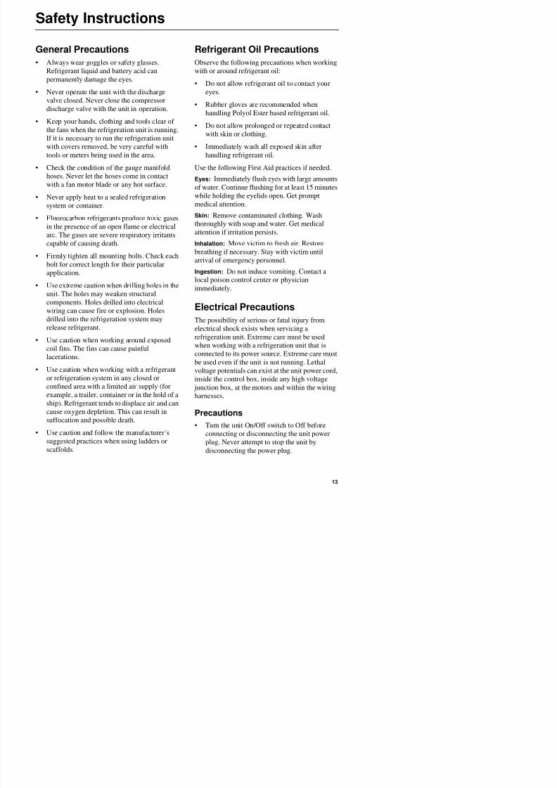
General Precautions
Always wear goggles or safety glasses.Refrigerant liquid and battery acid can
permanently damage the eyes.
• Never operate the unit with the discharge
valve closed. Never close the compressor
discharge valve with the unit in operation.
• Keep your hands, clothing and tools clear of
the fans when the refrigeration unit is running.
If it is necessary to run the refrigeration unit
with covers removed, be very careful with
tools or meters being used in the area.
• Check the condition of the gauge manifold
hoses. Never let the hoses come in contact
with a fan motor blade or any hot surface.
• Never apply heat to a sealed refrigeration
system or container.
• Fluorocarbon refrigerants produce toxic gases
in the presence of an open flame or electrical
arc. The gases are severe respiratory irritants
capable of causing death.
• Firmly tighten all mounting bolts. Check each
bolt for correct length for their particular
application.
• Use extreme caution when drilling holes in the
unit. The holes may weaken structural
components. Holes drilled into electrical
wiring can cause fire or explosion. Holes
drilled into the refrigeration system may
release refrigerant.
• Use caution when working around exposed
coil fins. The fins can cause painful
lacerations
Refrigerant Oil Precautions
Observe the following precautions when workingwith or around refrigerant oil:
• Do not allow refrigerant oil to contact your
eyes.
• Rubber gloves are recommended when
handling Polyol Ester based refrigerant oil.
• Do not allow prolonged or repeated contactwith skin or clothing.
• Immediately wash all exposed skin after
handling refrigerant oil.
Use the following First Aid practices if needed.
Eyes: Immediately flush eyes with large amounts
of water. Continue flushing for at least 15 minuteswhile holding the eyelids open. Get prompt
medical attention.
Skin: Remove contaminated clothing. Wash
thoroughly with soap and water. Get medical
attention if irritation persists.
Inhalation: Move victim to fresh air. Restore
breathing if necessary. Stay with victim untilarrival of emergency personnel.
Ingestion: Do not induce vomiting. Contact a
local poison control center or physician
immediately.
Electrical Precautions
The possibility of serious or fatal injury from
electrical shock exists when servicing a
refrigeration unit. Extreme care must be used
when working with a refrigeration unit that is
connected to its power source. Extreme care must
8/12/2019 Termo_King_Magnum_manual.pdf
http://slidepdf.com/reader/full/termokingmagnummanualpdf 14/194
Safety Instructions
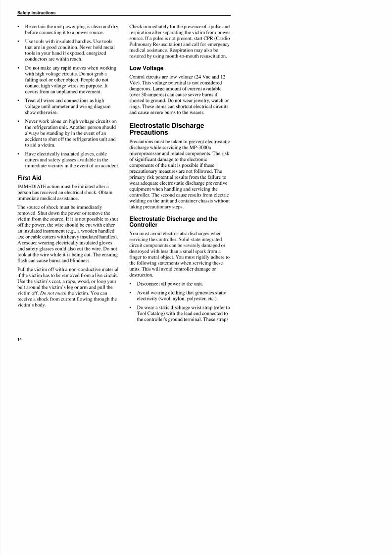
• Be certain the unit power plug is clean and dry
before connecting it to a power source.
• Use tools with insulated handles. Use tools
that are in good condition. Never hold metaltools in your hand if exposed, energized
conductors are within reach.
• Do not make any rapid moves when working
with high voltage circuits. Do not grab a
falling tool or other object. People do not
contact high voltage wires on purpose. It
occurs from an unplanned movement.
• Treat all wires and connections as high
voltage until ammeter and wiring diagram
show otherwise.
• Never work alone on high voltage circuits on
the refrigeration unit. Another person should
always be standing by in the event of anaccident to shut off the refrigeration unit and
to aid a victim.
• Have electrically insulated gloves, cable
cutters and safety glasses available in the
immediate vicinity in the event of an accident.
First AidIMMEDIATE action must be initiated after a
person has received an electrical shock. Obtain
immediate medical assistance.
The source of shock must be immediately
removed. Shut down the power or remove the
victim from the source. If it is not possible to shut
off the power, the wire should be cut with either
an insulated instrument (e.g., a wooden handled
axe or cable cutters with heavy insulated handles).
A rescuer wearing electrically insulated gloves
and safety glasses could also cut the wire. Do not
Check immediately for the presence of a pulse and
respiration after separating the victim from power
source. If a pulse is not present, start CPR (Cardio
Pulmonary Resuscitation) and call for emergencymedical assistance. Respiration may also be
restored by using mouth-to-mouth resuscitation.
Low Voltage
Control circuits are low voltage (24 Vac and 12
Vdc). This voltage potential is not considered
dangerous. Large amount of current available(over 30 amperes) can cause severe burns if
shorted to ground. Do not wear jewelry, watch or
rings. These items can shortcut electrical circuits
and cause severe burns to the wearer.
Electrostatic Discharge
PrecautionsPrecautions must be taken to prevent electrostatic
discharge while servicing the MP-3000a
microprocessor and related components. The risk
of significant damage to the electronic
components of the unit is possible if these
precautionary measures are not followed. The
primary risk potential results from the failure towear adequate electrostatic discharge preventive
equipment when handling and servicing the
controller. The second cause results from electric
welding on the unit and container chassis without
taking precautionary steps.
Electrostatic Discharge and theController
You must avoid electrostatic discharges when
servicing the controller. Solid-state integrated
circuit components can be severely damaged or
destroyed with less than a small spark from a
8/12/2019 Termo_King_Magnum_manual.pdf
http://slidepdf.com/reader/full/termokingmagnummanualpdf 15/194
Safety Instructions
are available at most electronic equipment
distributors. Do not wear these straps with
power applied to the unit.
• Avoid contacting the electronic componentson the circuit boards of the unit being
serviced.
• Leave the circuit boards in their static proof
packing materials until ready for installation.
• Return a defective controller for repair in the
same static protective packing materials fromwhich the replacement component was
removed.
• Check the wiring after servicing the unit for
possible errors. Complete this task before
restoring power.
Welding of Units or ContainersElectric welding can cause serious damage to
electronic circuits when performed on any portion
of the refrigeration unit, container or container
chassis with the refrigeration unit attached. It is
necessary to ensure that welding currents are not
allowed to flow through the electronic circuits of
the unit. The following statements must be rigidlyadhered to when servicing these units to avoid
damage or destruction.
• Disconnect all power to the refrigeration unit.
• Disconnect all quick-disconnect wire
harnesses from the back of the controller.
• Disconnect all wire harnesses from theRemote Monitor Modem (RMM).
• Switch all of the electrical circuit breakers in
the control box to the Off position.
• Weld unit and/or container per normal
welding procedures. Keep ground return
electrode as close to the area to be welded as
practical. This will reduce the likelihood ofstray welding currents passing through any
electrical or electronic circuits.
• The unit power cables, wiring and circuit
breakers must be restored to their normal
condition when the welding operation is
completed.
Removing Refrigerant Properly
Use a refrigerant recovery process that prevents or
absolutely minimizes refrigerant escaping to the
atmosphere. Fluorocarbon refrigerants are
classified as safe refrigerants when proper tools
and procedures are used. Certain precautions must
be observed when handling them or servicing aunit in which they are used.
Fluorocarbon refrigerants evaporate rapidly,
freezing anything they contact when exposed to
the atmosphere in the liquid state. In the event of
frost bite, attempt to protect the frozen area from
further injury, warm the affected area rapidly, and
maintain respiration.
• Eyes: For contact with liquid, immediately
flush eyes with large amounts of water and get
prompt medical attention.
• Skin: Flush area with large amounts of
lukewarm water. Do not apply heat. Remove
contaminated clothing and shoes. Wrap burnswith dry, sterile, bulky dressing to protect
from infection/injury. Get medical attention.
Wash contaminated clothing before reuse.
• Inhalation: Move victim to fresh air and use
CPR h h il i if
8/12/2019 Termo_King_Magnum_manual.pdf
http://slidepdf.com/reader/full/termokingmagnummanualpdf 16/194
Safety Instructions
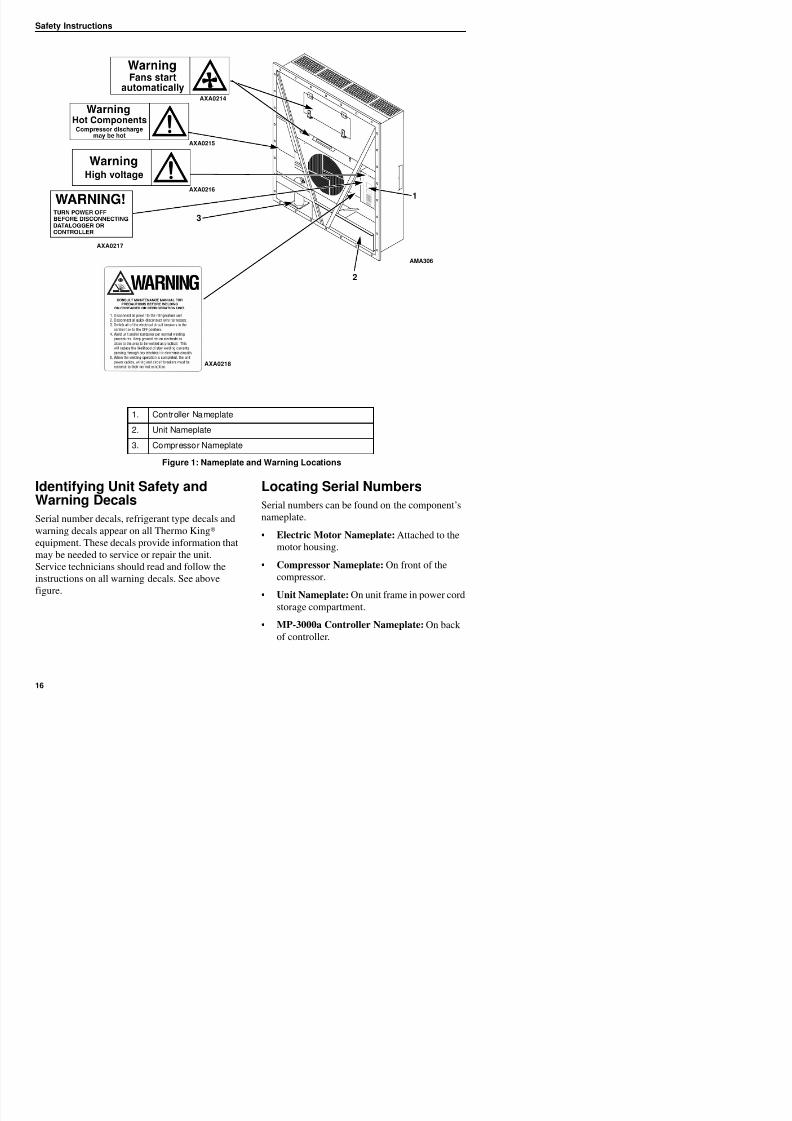
Identifying Unit Safety andWarning Decals
Locating Serial Numbers
Serial numbers can be found on the component’s
1. Controller Nameplate
2. Unit Nameplate
3. Compressor NameplateFigure 1: Nameplate and Warning Locations
2
AMA306
AXA0214
AXA0215
AXA0218
AXA0217
AXA0216
1
3
S i G id
8/12/2019 Termo_King_Magnum_manual.pdf
http://slidepdf.com/reader/full/termokingmagnummanualpdf 17/194
Service Guide
Service Guide
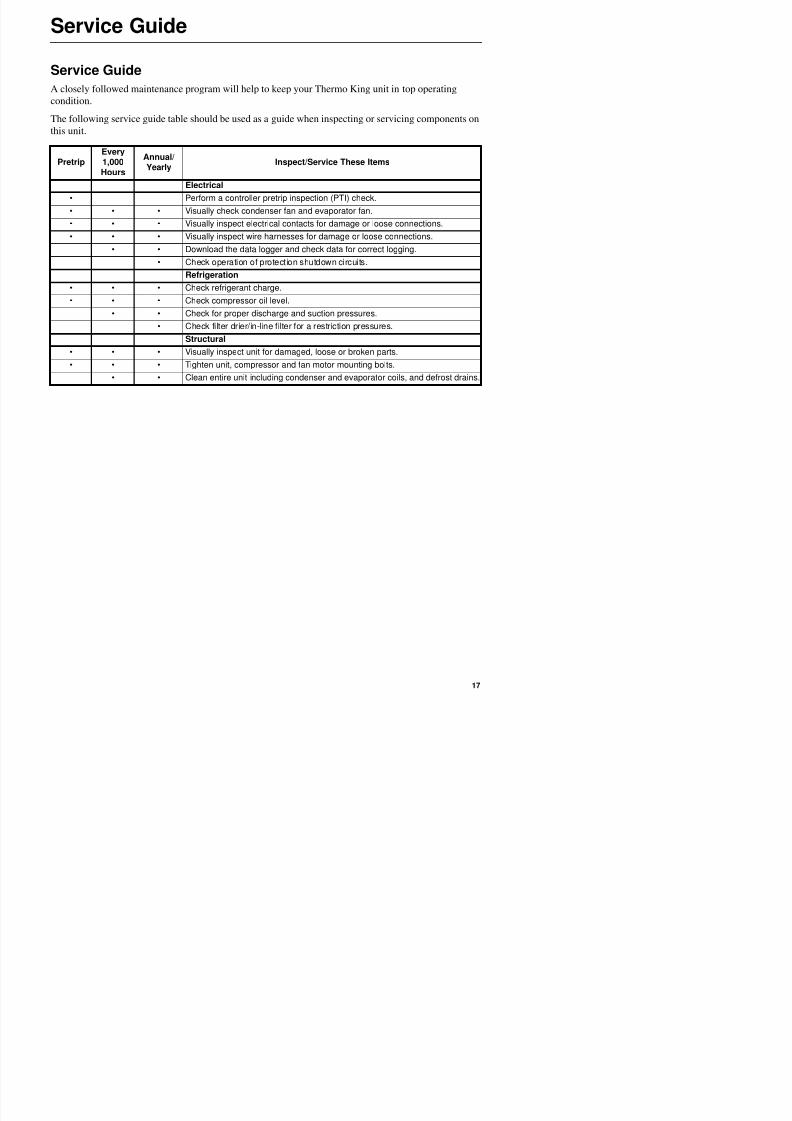
A closely followed maintenance program will help to keep your Thermo King unit in top operatingcondition.
The following service guide table should be used as a guide when inspecting or servicing components on
this unit.
PretripEvery1,000Hours
Annual/Yearly
Inspect/Service These Items
Electrical
• Perform a controller pretrip inspection (PTI) check.
• • • Visually check condenser fan and evaporator fan.
• • • Visually inspect electrical contacts for damage or loose connections.
• • • Visually inspect wire harnesses for damage or loose connections.
• • Download the data logger and check data for correct logging.
• Check operation of protection shutdown circuits.
Refrigeration
• • • Check refrigerant charge.
• • • Check compressor oil level.
• • Check for proper discharge and suction pressures.
• Check filter drier/in-line filter for a restriction pressures.
Structural
• • • Visually inspect unit for damaged, loose or broken parts.
• • • Tighten unit, compressor and fan motor mounting bolts.
• • Clean entire unit including condenser and evaporator coils, and defrost drains.

8/12/2019 Termo_King_Magnum_manual.pdf
http://slidepdf.com/reader/full/termokingmagnummanualpdf 18/194
Service Guide
Specifications
8/12/2019 Termo_King_Magnum_manual.pdf
http://slidepdf.com/reader/full/termokingmagnummanualpdf 19/194
Specifications
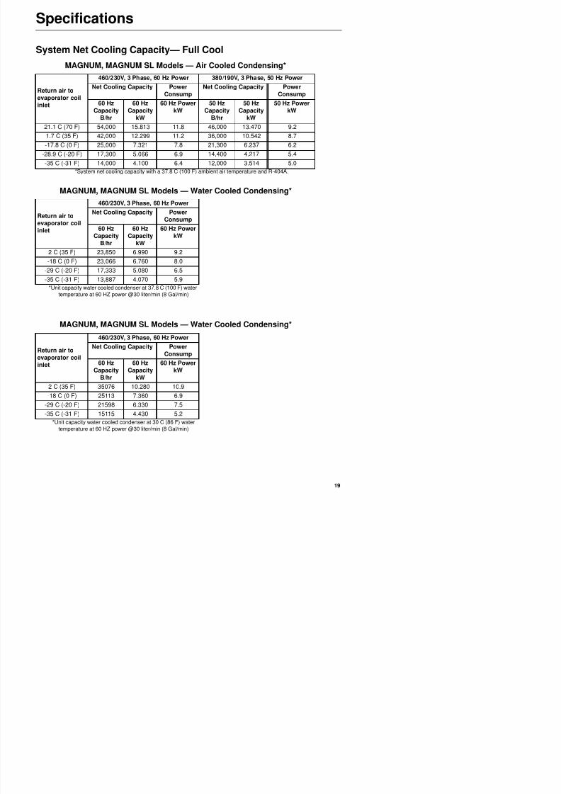
System Net Cooling Capacity— Full Cool
MAGNUM, MAGNUM SL Models — Air Cooled Condensing*
Return air toevaporator coilinlet
460/230V, 3 Phase, 60 Hz Power 380/190V, 3 Phase, 50 Hz Power
Net Cooling Capacity PowerConsump
Net Cooling Capacity PowerConsump
60 HzCapacity
B/hr
60 HzCapacity
kW
60 Hz PowerkW
50 HzCapacity
B/hr
50 HzCapacity
kW
50 Hz PowerkW
21.1 C (70 F) 54,000 15.813 11.8 46,000 13.470 9.21.7 C (35 F) 42,000 12.299 11.2 36,000 10.542 8.7
-17.8 C (0 F) 25,000 7.321 7.8 21,300 6.237 6.2
-28.9 C (-20 F) 17,300 5.066 6.9 14,400 4.217 5.4
-35 C (-31 F) 14,000 4.100 6.4 12,000 3.514 5.0
*System net cooling capacity with a 37.8 C (100 F) ambient air temperature and R-404A.
MAGNUM, MAGNUM SL Models — Water Cooled Condensing*
Return air toevaporator coilinlet
460/230V, 3 Phase, 60 Hz Power
Net Cooling Capacity PowerConsump
60 HzCapacity
B/hr
60 HzCapacity
kW
60 Hz PowerkW
2 C (35 F) 23,850 6.990 9.2-18 C (0 F) 23,066 6.760 8.0
-29 C (-20 F) 17,333 5.080 6.5
-35 C (-31 F) 13,887 4.070 5.9
*Unit capacity water cooled condenser at 37.8 C (100 F) water
temperature at 60 HZ power @30 liter/min (8 Gal/min)
MAGNUM, MAGNUM SL Models — Water Cooled Condensing*
Return air toevaporator coil
460/230V, 3 Phase, 60 Hz Power
Net Cooling Capacity PowerConsump
S ifi ti
8/12/2019 Termo_King_Magnum_manual.pdf
http://slidepdf.com/reader/full/termokingmagnummanualpdf 20/194
Specifications
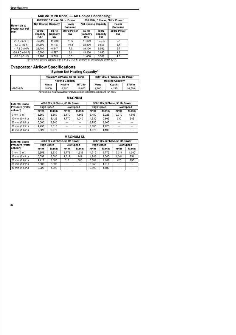
MAGNUM 20 Model — Air Cooled Condensing*
Evaporator Airflow Specifications
MAGNUM SL
Return air to
evaporator coilinlet
460/230V, 3 Phase, 60 Hz Power 380/190V, 3 Phase, 50 Hz Power
Net Cooling Capacity Power
Consump
Net Cooling Capacity Power
Consump60 Hz
CapacityB/hr
60 HzCapacity
kW
60 Hz PowerkW
50 HzCapacity
B/hr
50 HzCapacity
kW
50 Hz PowerkW
21.1 C (70 F) 49,000 14.348 11.6 41,800 12.240 9.1
1.7 C (35 F) 31,800 11.157 10.8 32,800 9.605 8.4
-17.8 C (0 F) 22,700 6.647 7.2 19,100 5.593 5.7
-28.9 C (-20 F) 15,700 4.597 6.1 13,300 3.895 4.8
-35 C (-31 F) 12,700 3.719 5.5 11,400 3.338 4.3
*System net cooling capacity with a 37.8 C (100 F) ambient air temperature and R-404A.
System Net Heating Capacity*
460/230V, 3 Phase, 60 Hz Power 380/190V, 3 Phase, 50 Hz Power
Heating Capacity Heating CapacityWatts Kcal/hr BTU/hr Watts Kcal/hr BTU/hr
MAGNUM 5,800 4,990 19,800 4,900 4,215 16,720
*System net heating capacity includes electric resistance rods and fan heat.
MAGNUM
External Static
Pressure (watercolumn)
460/230V, 3 Phase, 60 Hz Power 380/190V, 3 Phase, 50 Hz Power
High Speed Low Speed High Speed Low Speedm3/hr ft3/min m3/hr ft3/min m3/hr ft3/min m3/hr ft3/min
0 mm (0 in.) 6,560 3,860 3,170 1,865 5,480 3,225 2,710 1,595
10 mm (0.4 in.) 5,820 3,425 1,770 1,040 4,530 2,665 930 545
20 mm (0.8 in.) 5,000 2,940 — — 3,750 2,205 — —
30 mm (1.2 in.) 4,430 2,610 — — 2,930 1,725 — —
40 mm (1.6 in.) 3,520 2,070 — — 1,870 1,100 — —
External StaticPressure (watercolumn)
460/230V, 3 Phase, 60 Hz Power 380/190V, 3 Phase, 50 Hz Power
High Speed Low Speed High Speed Low Speed
m3/hr ft3/min m3/hr ft3/min m3/hr ft3/min m3/hr ft3/min
0 (0 i ) 5 658 3 330 2 773 1 632 4 715 2 775 2 311 1 360
Specifications
8/12/2019 Termo_King_Magnum_manual.pdf
http://slidepdf.com/reader/full/termokingmagnummanualpdf 21/194
Specifications
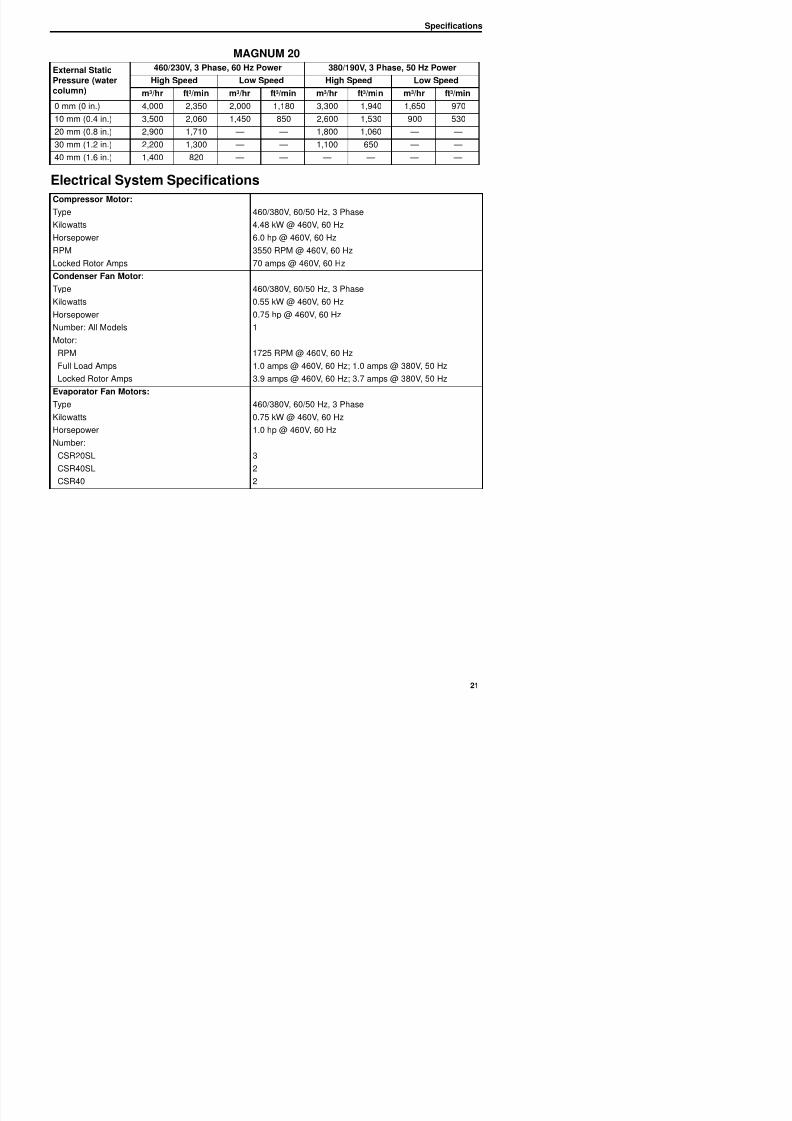
MAGNUM 20
External StaticPressure (water
column)
460/230V, 3 Phase, 60 Hz Power 380/190V, 3 Phase, 50 Hz Power
High Speed Low Speed High Speed Low Speed
m3/hr ft3/min m3/hr ft3/min m3/hr ft3/min m3/hr ft3/min0 mm (0 in.) 4,000 2,350 2,000 1,180 3,300 1,940 1,650 970
10 mm (0.4 in.) 3,500 2,060 1,450 850 2,600 1,530 900 530
20 mm (0.8 in.) 2,900 1,710 — — 1,800 1,060 — —
30 mm (1.2 in.) 2,200 1,300 — — 1,100 650 — —
40 mm (1.6 in.) 1,400 820 — — — — — —
Electrical System SpecificationsCompressor Motor:
Type 460/380V, 60/50 Hz, 3 Phase
Kilowatts 4.48 kW @ 460V, 60 Hz
Horsepower 6.0 hp @ 460V, 60 Hz
RPM 3550 RPM @ 460V, 60 Hz
Locked Rotor Amps 70 amps @ 460V, 60 Hz
Condenser Fan Motor:
Type 460/380V, 60/50 Hz, 3 Phase
Kilowatts 0.55 kW @ 460V, 60 Hz
Horsepower 0.75 hp @ 460V, 60 Hz
Number: All Models 1
Motor:
RPM 1725 RPM @ 460V, 60 Hz
Full Load Amps 1.0 amps @ 460V, 60 Hz; 1.0 amps @ 380V, 50 Hz
Locked Rotor Amps 3.9 amps @ 460V, 60 Hz; 3.7 amps @ 380V, 50 Hz
Evaporator Fan Motors:
Type 460/380V, 60/50 Hz, 3 Phase
Kilowatts 0.75 kW @ 460V, 60 Hz
Horsepower 1.0 hp @ 460V, 60 Hz
Number:
CSR20SL 3
CSR40SL 2
CSR40 2
Specifications
8/12/2019 Termo_King_Magnum_manual.pdf
http://slidepdf.com/reader/full/termokingmagnummanualpdf 22/194
Specifications
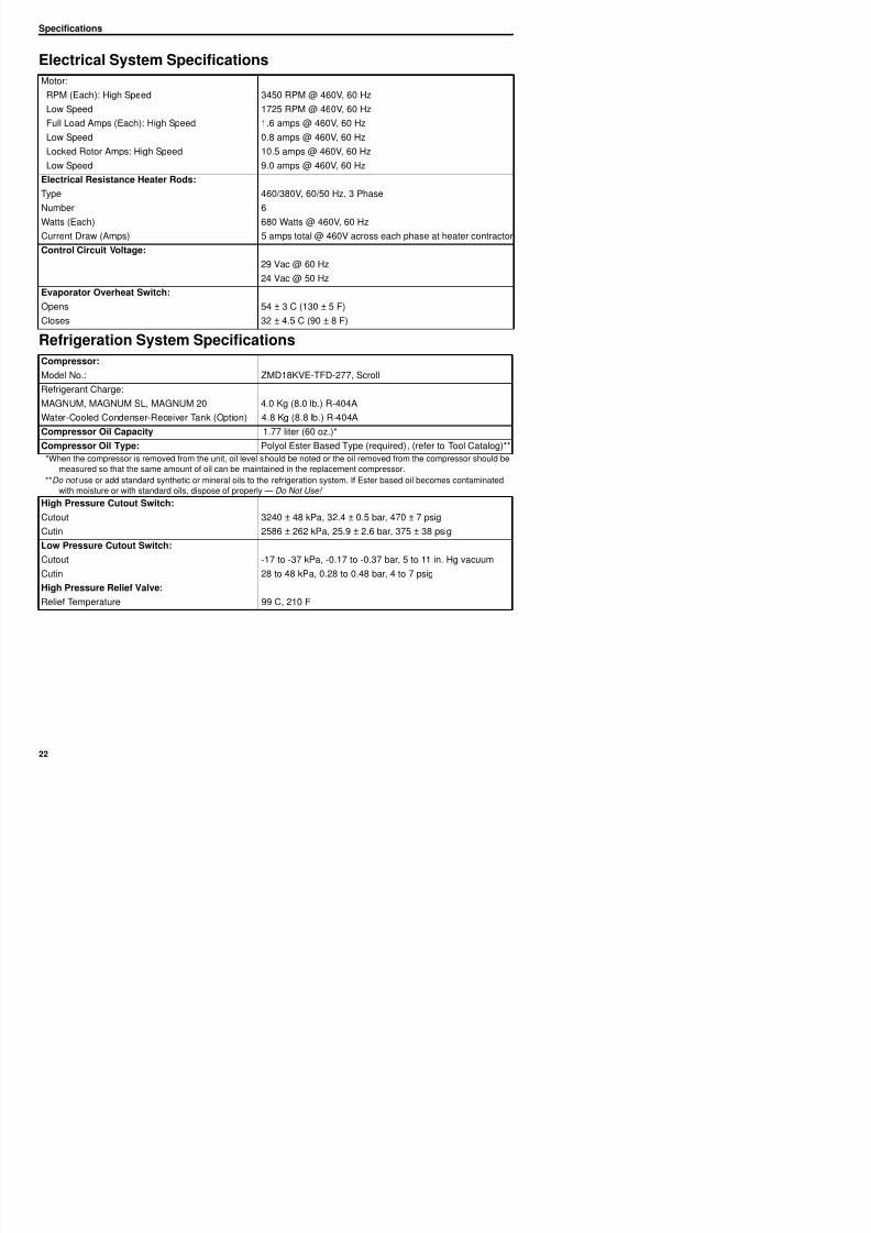
Motor:
RPM (Each): High Speed 3450 RPM @ 460V, 60 Hz
Low Speed 1725 RPM @ 460V, 60 Hz
Full Load Amps (Each): High Speed 1.6 amps @ 460V, 60 Hz
Low Speed 0.8 amps @ 460V, 60 Hz
Locked Rotor Amps: High Speed 10.5 amps @ 460V, 60 Hz
Low Speed 9.0 amps @ 460V, 60 Hz
Electrical Resistance Heater Rods:
Type 460/380V, 60/50 Hz, 3 Phase
Number 6
Watts (Each) 680 Watts @ 460V, 60 Hz
Current Draw (Amps) 5 amps total @ 460V across each phase at heater contractor
Control Circuit Voltage:
29 Vac @ 60 Hz
24 Vac @ 50 Hz
Evaporator Overheat Switch:
Opens 54 ± 3 C (130 ± 5 F)
Closes 32 ± 4.5 C (90 ± 8 F)
Refrigeration System Specifications
Compressor:
Model No.: ZMD18KVE-TFD-277, Scroll
Refrigerant Charge:
MAGNUM, MAGNUM SL, MAGNUM 20 4.0 Kg (8.0 lb.) R-404A
Water-Cooled Condenser-Receiver Tank (Option) 4.8 Kg (8.8 lb.) R-404A
Compressor Oil Capacity 1.77 liter (60 oz.)*
Compressor Oil Type: Polyol Ester Based Type (required), (refer to Tool Catalog)**
*When the compressor is removed from the unit, oil level should be noted or the oil removed from the compressor should be
measured so that the same amount of oil can be maintained in the replacement compressor.
**Do not use or add standard synthetic or mineral oils to the refrigeration system. If Ester based oil becomes contaminated
with moisture or with standard oils, dispose of properly — Do Not Use!
High Pressure Cutout Switch:
Cutout 3240 ± 48 kPa, 32.4 ± 0.5 bar, 470 ± 7 psig
Cutin 2586 ± 262 kPa, 25.9 ± 2.6 bar, 375 ± 38 psig
Low Pressure Cutout Switch:
Cutout 17 to 37 kPa 0 17 to 0 37 bar 5 to 11 in Hg vacuum
Electrical System Specifications
Specifications
8/12/2019 Termo_King_Magnum_manual.pdf
http://slidepdf.com/reader/full/termokingmagnummanualpdf 23/194
Specifications
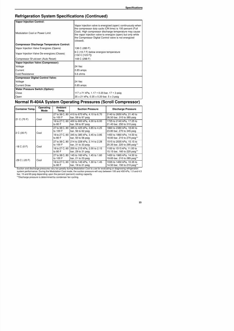
Vapor Injection Control:
Modulation Cool or Power Limit
Vapor injection valve is energized (open) continuously when
the compressor duty cycle (ON time) is 100 percent (FullCool). High compressor discharge temperature may causethe vapor injection valve to energize (open) but only whilethe Compressor Digital Control valve is not energized(closed).
Compressor Discharge Temperature Control:
Vapor Injection Valve Energizes (Opens) 138 C (280 F)
Vapor Injection Valve De-energizes (Closes)
6 C (10.7 F) below energize temperature
(132 C [123 F])
Compressor Shutdown (Auto Reset) 148 C (298 F)
Vapor Injection Valve (Compressor):
Voltage 24 Vac
Current 0.85 amps
Cold Resistance 5.6 ohms
Compressor Digital Control Valve:
Voltage 24 Vac
Current Draw 0.85 amps
Water Pressure Switch (Option):
Close 117 ± 21 kPa, 1.17 ± 0.20 bar, 17 ± 3 psig
Open 35 ± 21 kPa, 0.35 ± 0.20 bar, 5 ± 3 psig
Normal R-404A System Operating Pressures (Scroll Compressor)
Container Temp.Operating
ModeAmbient
Temp.Suction Pressure Discharge Pressure
21 C (70 F) Cool
27 to 38 C, 80to 100 F
410 to 670 kPa, 4.10 to 6.70bar, 59 to 97 psig
2140 to 2650 kPa, 21.40 to26.50 bar, 310 to 385 psig
16 to 27 C, 60to 80 F
400 to 600 kPa, 4.00 to 6.00bar, 58 to 87 psig
1725 to 2140 kPa, 17.25 to21.40 bar, 250 to 310 psig
2 C (35 F) Cool
27 to 38 C, 80to 100 F
385 to 425 kPa, 3.85 to 4.25bar, 56 to 62 psig
1860 to 2380 kPa, 18.60 to23.80 bar, 270 to 345 psig
16 to 27 C, 60to 80 F
345 to 385 kPa, 3.45 to 3.85bar, 50 to 56 psig
1450 to 1860 kPa, 14.50 to18.60 bar, 210 to 270 psig**
-18 C (0 F) Cool
27 to 38 C, 80to 100 F
214 to 228 kPa, 2.14 to 2.28bar, 31 to 33 psig
1515 to 2035 kPa, 15.15 to20.35 bar, 220 to 295 psig**
16 to 27 C, 60 200 to 215 kPa, 2.00 to 2.15 1100 to 1515 kPa, 11.00 to
Refrigeration System Specifications (Continued)
Specifications
8/12/2019 Termo_King_Magnum_manual.pdf
http://slidepdf.com/reader/full/termokingmagnummanualpdf 24/194
Specifications
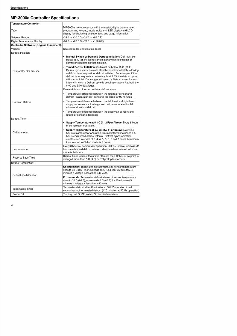
MP-3000a Controller Specifications
Temperature Controller:
TypeMP-3000a microprocessor with thermostat, digital thermometer,programming keypad, mode indicators, LED display and LCDdisplay for displaying unit operating and cargo information
Setpoint Range -35.0 to +30.0 C (-31.0 to +86.0 F)
Digital Temperature Display -60.0 to +80.0 C (-76.0 to +176.0 F)
Controller Software (Original Equipment):
Version See controller identification decal
Defrost Initiation:
Evaporator Coil Sensor
• Manual Switch or Demand Defrost Initiation: Coil must bebelow 18 C (65 F). Defrost cycle starts when technician orcontroller requests defrost initiation.
• Timed Defrost Initiation: Coil must be below 10 C (50 F).Defrost cycle starts 1 minute after the hour immediately followinga defrost timer request for defrost initiation. For example, if thedefrost timer requests a defrost cycle at 7:35, the defrost cyclewill start at 8:01. Datalogger will record a Defrost event for each
interval in which a Defrost cycle is pending or active (i.e. both the8:00 and 9:00 data logs).
Demand Defrost
Demand defrost function initiates defrost when:
• Temperature difference between the return air sensor anddefrost (evaporator coil) sensor is too large for 90 minutes
• Temperature difference between the left hand and right handsupply air sensors is too large and unit has operated for 90
minutes since last defrost• Temperature difference between the supply air sensors and
return air sensor is too large
Defrost Timer:
Chilled mode
• Supply Temperature at 5.1 C (41.2 F) or Above: Every 8 hoursof compressor operation.
• Supply Temperature at 5.0 C (41.0 F) or Below: Every 2.5hours of compressor operation. Defrost interval increases 0.5
hours each timed defrost interval. Defrost synchronizationcreates step intervals of 3, 4, 4, 5, 5, 6, 6 and 7 hours. Maximumtime interval in Chilled mode is 7 hours.
Frozen modeEvery 8 hours of compressor operation. Defrost interval increases 2hours each timed defrost interval. Maximum time interval in Frozenmode is 24 hours
Specifications
8/12/2019 Termo_King_Magnum_manual.pdf
http://slidepdf.com/reader/full/termokingmagnummanualpdf 25/194
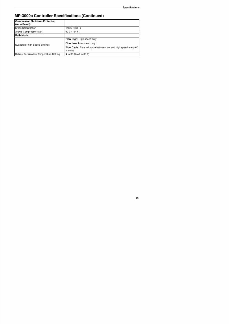
p
Compressor Shutdown Protection(Auto Reset):
Stops Compressor 148 C (298 F)
Allows Compressor Start 90 C (194 F)
Bulb Mode:
Evaporator Fan Speed Settings
Flow High: High speed only
Flow Low: Low speed only
Flow Cycle: Fans will cycle between low and high speed every 60minutes
Defrost Termination Temperature Setting 4 to 30 C (40 to 86 F)
MP-3000a Controller Specifications (Continued)
Specifications
8/12/2019 Termo_King_Magnum_manual.pdf
http://slidepdf.com/reader/full/termokingmagnummanualpdf 26/194
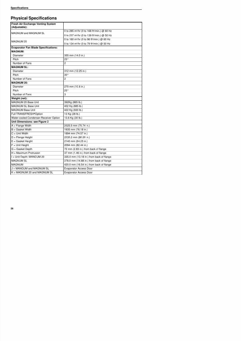
Physical Specifications
Fresh Air Exchange Venting System(Adjustable):
MAGNUM and MAGNUM SL0 to 285 m3 /hr (0 to 168 ft3 /min.) @ 60 Hz
0 to 237 m3 /hr (0 to 139 ft3 /min.) @ 50 Hz
MAGNUM 200 to 160 m3 /hr (0 to 96 ft3 /min.) @ 60 Hz
0 to 134 m3 /hr (0 to 79 ft3 /min.) @ 50 Hz
Evaporator Fan Blade Specifications:
MAGNUM:
Diameter 355 mm (14.0 in.)Pitch 25°
Number of Fans 2
MAGNUM SL:
Diameter 312 mm (12.25 in.)
Pitch 30°
Number of Fans 2
MAGNUM 20:Diameter 270 mm (10.6 in.)
Pitch 25°
Number of Fans 3
Weight (net):
MAGNUM 20 Base Unit 392Kg (865 lb.)
MAGNUM SL Base Unit 402 Kg (885 lb.)
MAGNUM Base Unit 422 Kg (930 lb.)Full TRANSFRESH ® Option 13 Kg (28 lb.)
Water-cooled Condenser-Receiver Option 13.6 Kg (30 lb.)
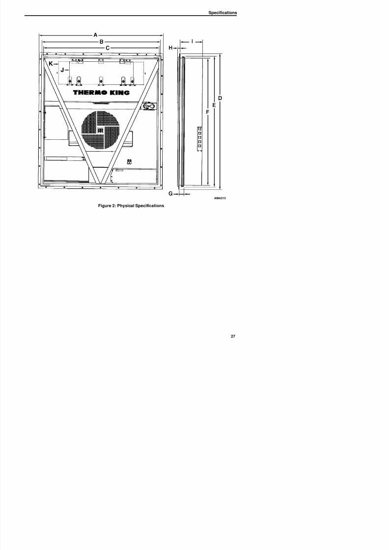
Unit Dimensions: see Figure 2
A = Flange Width 2025.5 mm (79.74 in.)
B = Gasket Width 1935 mm (76.18 in.)
C = Unit Width 1894 mm (74.57 in.)
D = Flange Height 2235.2 mm (88.00 in.)E = Gasket Height 2140 mm (84.25 in.)
F = Unit Height 2094 mm (82.44 in.)
G = Gasket Depth 72 mm (2.83 in.) from back of flange
H = Maximum Protrusion 37 mm (1.46 in.) from back of flange
Specifications
8/12/2019 Termo_King_Magnum_manual.pdf
http://slidepdf.com/reader/full/termokingmagnummanualpdf 27/194
Figure 2: Physical Specifications
AMA313
Specifications
8/12/2019 Termo_King_Magnum_manual.pdf
http://slidepdf.com/reader/full/termokingmagnummanualpdf 28/194
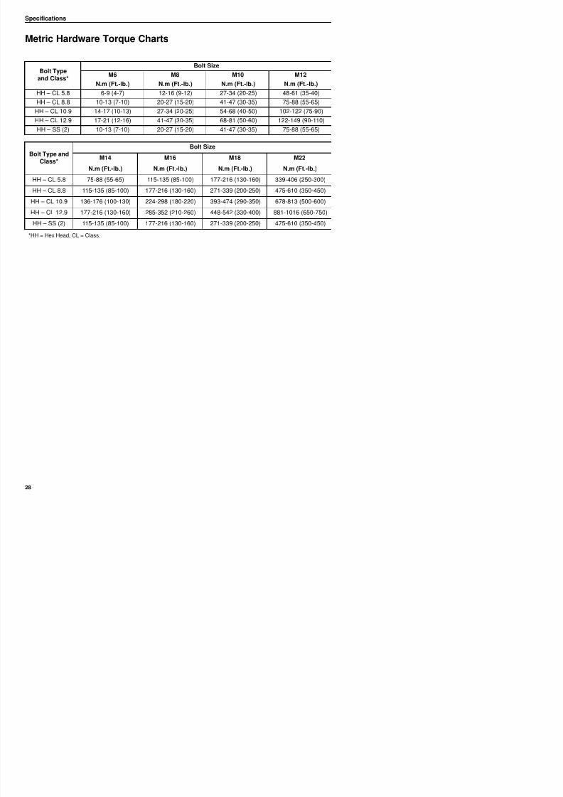
Metric Hardware Torque Charts
*HH = Hex Head, CL = Class.
Bolt Typeand Class*
Bolt SizeM6 M8 M10 M12
N.m (Ft.-lb.) N.m (Ft.-lb.) N.m (Ft.-lb.) N.m (Ft.-lb.)
HH – CL 5.8 6-9 (4-7) 12-16 (9-12) 27-34 (20-25) 48-61 (35-40)
HH – CL 8.8 10-13 (7-10) 20-27 (15-20) 41-47 (30-35) 75-88 (55-65)
HH – CL 10.9 14-17 (10-13) 27-34 (20-25) 54-68 (40-50) 102-122 (75-90)
HH – CL 12.9 17-21 (12-16) 41-47 (30-35) 68-81 (50-60) 122-149 (90-110)
HH – SS (2) 10-13 (7-10) 20-27 (15-20) 41-47 (30-35) 75-88 (55-65)
Bolt Type andClass*
Bolt Size
M14 M16 M18 M22
N.m (Ft.-lb.) N.m (Ft.-lb.) N.m (Ft.-lb.) N.m (Ft.-lb.)
HH – CL 5.8 75-88 (55-65) 115-135 (85-100) 177-216 (130-160) 339-406 (250-300)
HH – CL 8.8 115-135 (85-100) 177-216 (130-160) 271-339 (200-250) 475-610 (350-450)
HH – CL 10.9 136-176 (100-130) 224-298 (180-220) 393-474 (290-350) 678-813 (500-600)
HH – CL 12.9 177-216 (130-160) 285-352 (210-260) 448-542 (330-400) 881-1016 (650-750)
HH – SS (2) 115-135 (85-100) 177-216 (130-160) 271-339 (200-250) 475-610 (350-450)
Unit Description, Features & Options
8/12/2019 Termo_King_Magnum_manual.pdf
http://slidepdf.com/reader/full/termokingmagnummanualpdf 29/194
p , p
Introduction
This chapter will briefly describe the following
items:
• General Unit Description.
• Standard Component Descriptions.
• Optional Component Descriptions.
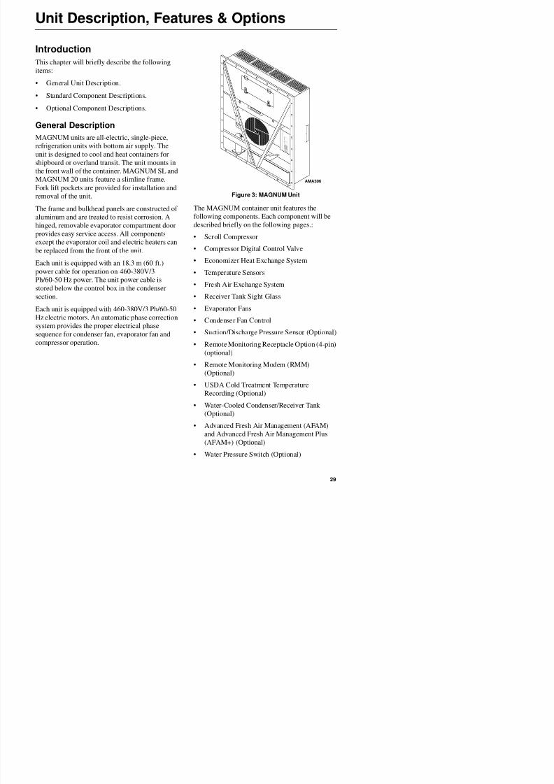
General DescriptionMAGNUM units are all-electric, single-piece,
refrigeration units with bottom air supply. The
unit is designed to cool and heat containers for
shipboard or overland transit. The unit mounts in
the front wall of the container. MAGNUM SL and
MAGNUM 20 units feature a slimline frame.
Fork lift pockets are provided for installation andremoval of the unit.
The frame and bulkhead panels are constructed of
aluminum and are treated to resist corrosion. A
hinged, removable evaporator compartment door
provides easy service access. All components
except the evaporator coil and electric heaters can
be replaced from the front of the unit.Each unit is equipped with an 18.3 m (60 ft.)
power cable for operation on 460-380V/3
Ph/60-50 Hz power. The unit power cable is
stored below the control box in the condenser
section.
Each unit is equipped with 460-380V/3 Ph/60-50
Hz electric motors. An automatic phase correctionsystem provides the proper electrical phase
sequence for condenser fan, evaporator fan and
compressor operation.
Figure 3: MAGNUM Unit
The MAGNUM container unit features the
following components. Each component will be
described briefly on the following pages.:
• Scroll Compressor
• Compressor Digital Control Valve
• Economizer Heat Exchange System
• Temperature Sensors
• Fresh Air Exchange System
• Receiver Tank Sight Glass
• Evaporator Fans
• Condenser Fan Control
• Suction/Discharge Pressure Sensor (Optional)
• Remote Monitoring Receptacle Option (4-pin)
(optional)
AMA306
Unit Description, Features & Options
8/12/2019 Termo_King_Magnum_manual.pdf
http://slidepdf.com/reader/full/termokingmagnummanualpdf 30/194
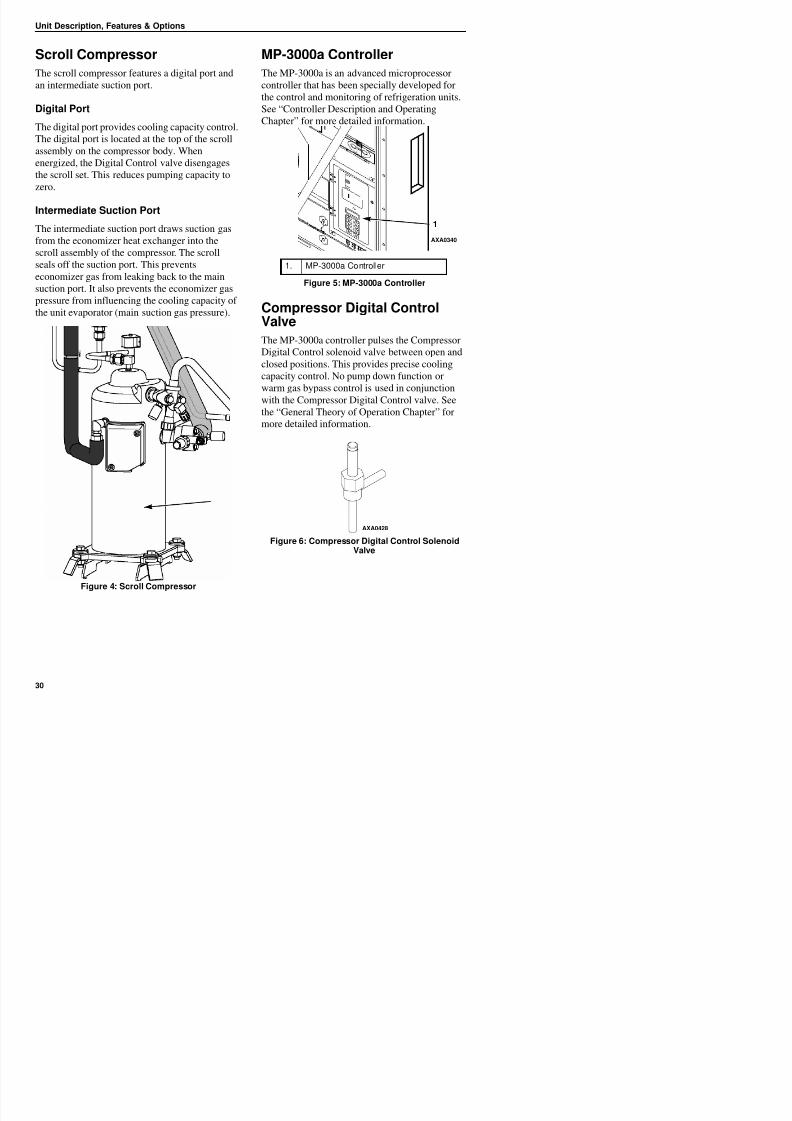
Scroll Compressor
The scroll compressor features a digital port and
an intermediate suction port.
Digital Port
The digital port provides cooling capacity control.
The digital port is located at the top of the scroll
assembly on the compressor body. When
energized, the Digital Control valve disengages
the scroll set. This reduces pumping capacity to
zero.
Intermediate Suction Port
The intermediate suction port draws suction gas
from the economizer heat exchanger into the
scroll assembly of the compressor. The scroll
seals off the suction port. This prevents
economizer gas from leaking back to the mainsuction port. It also prevents the economizer gas
pressure from influencing the cooling capacity of
the unit evaporator (main suction gas pressure).
MP-3000a Controller
The MP-3000a is an advanced microprocessor
controller that has been specially developed for
the control and monitoring of refrigeration units.See “Controller Description and Operating
Chapter” for more detailed information.
Compressor Digital ControlValve
The MP-3000a controller pulses the Compressor
Digital Control solenoid valve between open and
closed positions. This provides precise coolingcapacity control. No pump down function or
warm gas bypass control is used in conjunction
with the Compressor Digital Control valve. See
the “General Theory of Operation Chapter” for
more detailed information.
1. MP-3000a Controller
Figure 5: MP-3000a Controller
1
AXA0340
Unit Description, Features & Options
8/12/2019 Termo_King_Magnum_manual.pdf
http://slidepdf.com/reader/full/termokingmagnummanualpdf 31/194
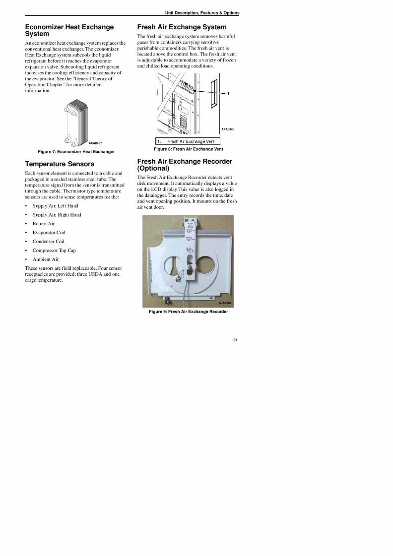
Economizer Heat ExchangeSystem
An economizer heat exchange system replaces the
conventional heat exchanger. The economizerHeat Exchange system subcools the liquid
refrigerant before it reaches the evaporator
expansion valve. Subcooling liquid refrigerant
increases the cooling efficiency and capacity of
the evaporator. See the “General Theory of
Operation Chapter” for more detailed
information.
Figure 7: Economizer Heat Exchanger
Temperature Sensors
Each sensor element is connected to a cable and
packaged in a sealed stainless steel tube. Thetemperature signal from the sensor is transmitted
through the cable. Thermistor type temperature
sensors are used to sense temperatures for the:
• Supply Air, Left Hand
• Supply Air, Right Hand
• Return Air
• Evaporator Coil
• Condenser Coil
• Compressor Top Cap
Fresh Air Exchange System
The fresh air exchange system removes harmful
gases from containers carrying sensitive
perishable commodities. The fresh air vent islocated above the control box. The fresh air vent
is adjustable to accommodate a variety of frozen
and chilled load operating conditions.
Fresh Air Exchange Recorder(Optional)
The Fresh Air Exchange Recorder detects vent
disk movement. It automatically displays a value
on the LCD display.This value is also logged in
the datalogger. The entry records the time, date
and vent opening position. It mounts on the fresh
air vent door.
AXA0427 1. Fresh Air Exchange Vent
Figure 8: Fresh Air Exchange Vent
1
AXA0340
Unit Description, Features & Options
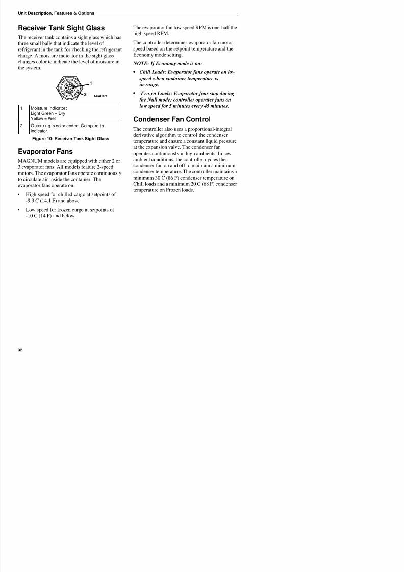
8/12/2019 Termo_King_Magnum_manual.pdf
http://slidepdf.com/reader/full/termokingmagnummanualpdf 32/194
Receiver Tank Sight Glass
The receiver tank contains a sight glass which has
three small balls that indicate the level of
refrigerant in the tank for checking the refrigerantcharge. A moisture indicator in the sight glass
changes color to indicate the level of moisture in
the system.
Evaporator Fans
MAGNUM models are equipped with either 2 or
3 evaporator fans. All models feature 2-speed
motors. The evaporator fans operate continuously
to circulate air inside the container. The
evaporator fans operate on:
• High speed for chilled cargo at setpoints of
-9.9 C (14.1 F) and above
• Low speed for frozen cargo at setpoints of
-10 C (14 F) and below
The evaporator fan low speed RPM is one-half the
high speed RPM.
The controller determines evaporator fan motor
speed based on the setpoint temperature and theEconomy mode setting.
NOTE: If Economy mode is on:
• Chill Loads: Evaporator fans operate on low
speed when container temperature is
in-range.
• Frozen Loads: Evaporator fans stop during the Null mode; controller operates fans on
low speed for 5 minutes every 45 minutes.
Condenser Fan Control
The controller also uses a proportional-integral
derivative algorithm to control the condenser
temperature and ensure a constant liquid pressureat the expansion valve. The condenser fan
operates continuously in high ambients. In low
ambient conditions, the controller cycles the
condenser fan on and off to maintain a minimum
condenser temperature. The controller maintains a
minimum 30 C (86 F) condenser temperature on
Chill loads and a minimum 20 C (68 F) condensertemperature on Frozen loads.
1. Moisture Indicator:Light Green = DryYellow = Wet
2. Outer ring is color coded. Compare toindicator.
Figure 10: Receiver Tank Sight Glass
AXA0371
Unit Description, Features & Options
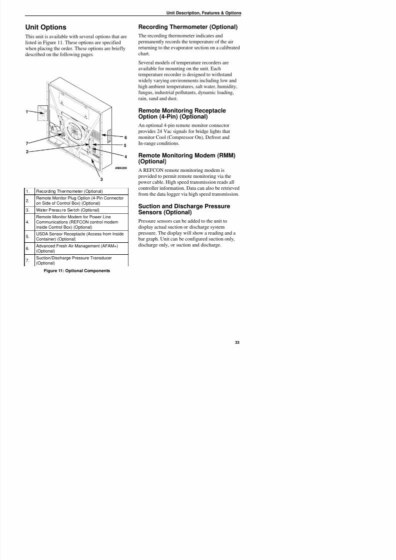
8/12/2019 Termo_King_Magnum_manual.pdf
http://slidepdf.com/reader/full/termokingmagnummanualpdf 33/194
Unit Options
This unit is available with several options that are
listed in Figure 11. These options are specified
when placing the order. These options are brieflydescribed on the following pages.
Recording Thermometer (Optional)
The recording thermometer indicates and
permanently records the temperature of the air
returning to the evaporator section on a calibratedchart.
Several models of temperature recorders are
available for mounting on the unit. Each
temperature recorder is designed to withstand
widely varying environments including low and
high ambient temperatures, salt water, humidity,
fungus, industrial pollutants, dynamic loading,rain, sand and dust.
Remote Monitoring ReceptacleOption (4-Pin) (Optional)
An optional 4-pin remote monitor connector
provides 24 Vac signals for bridge lights that
monitor Cool (Compressor On), Defrost andIn-range conditions.
Remote Monitoring Modem (RMM)(Optional)
A REFCON remote monitoring modem is
provided to permit remote monitoring via the
power cable. High speed transmission reads allcontroller information. Data can also be retrieved
from the data logger via high speed transmission.
Suction and Discharge PressureSensors (Optional)
Pressure sensors can be added to the unit to
display actual suction or discharge systempressure. The display will show a reading and a
bar graph. Unit can be configured suction only,
discharge only, or suction and discharge.
1. Recording Thermometer (Optional)
2.Remote Monitor Plug Option (4-Pin Connectoron Side of Control Box) (Optional)
3. Water Pressure Switch (Optional)
4.Remote Monitor Modem for Power LineCommunications (REFCON control modem
inside Control Box) (Optional)
5.USDA Sensor Receptacle (Access from InsideContainer) (Optional)
6.Advanced Fresh Air Management (AFAM+)(Optional)
AMA309
1
76
5
4
3
2
Unit Description, Features & Options
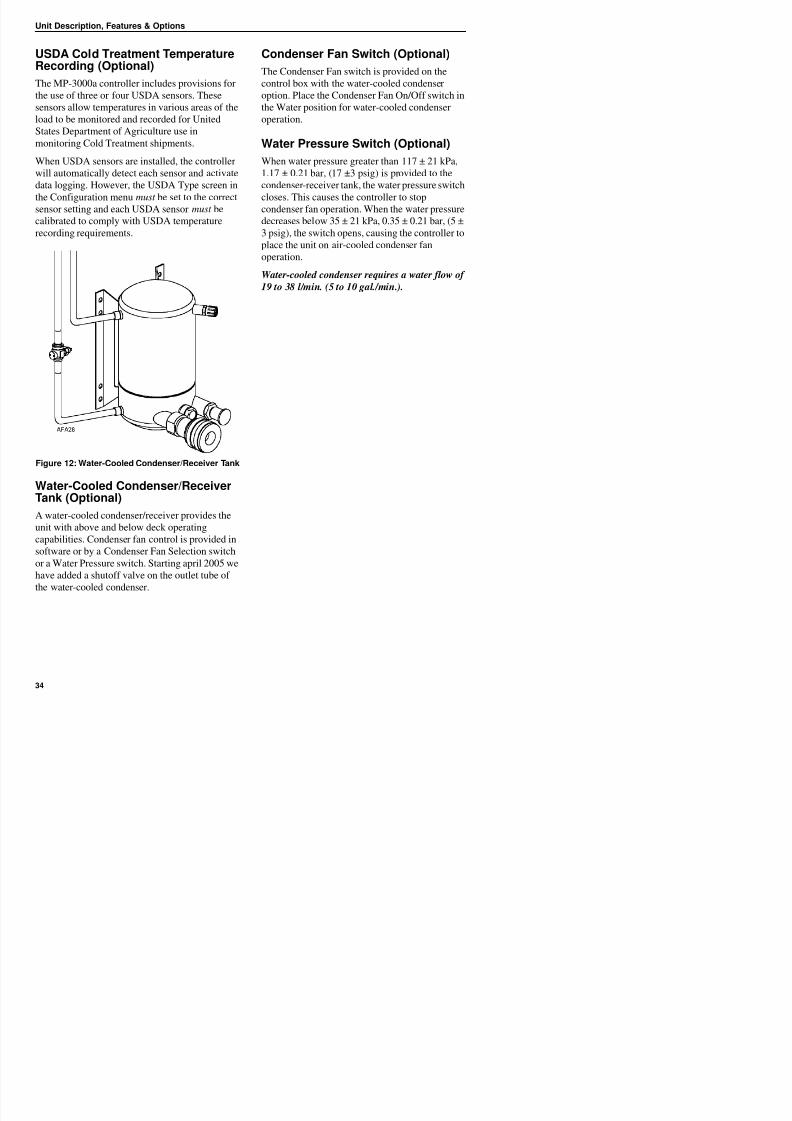
8/12/2019 Termo_King_Magnum_manual.pdf
http://slidepdf.com/reader/full/termokingmagnummanualpdf 34/194
USDA Cold Treatment TemperatureRecording (Optional)
The MP-3000a controller includes provisions for
the use of three or four USDA sensors. Thesesensors allow temperatures in various areas of the
load to be monitored and recorded for United
States Department of Agriculture use in
monitoring Cold Treatment shipments.
When USDA sensors are installed, the controller
will automatically detect each sensor and activate
data logging. However, the USDA Type screen inthe Configuration menu must be set to the correct
sensor setting and each USDA sensor must be
calibrated to comply with USDA temperature
recording requirements.
Figure 12: Water-Cooled Condenser/Receiver Tank
Water-Cooled Condenser/ReceiverTank (Optional)
Condenser Fan Switch (Optional)
The Condenser Fan switch is provided on the
control box with the water-cooled condenser
option. Place the Condenser Fan On/Off switch inthe Water position for water-cooled condenser
operation.
Water Pressure Switch (Optional)
When water pressure greater than 117 ± 21 kPa,
1.17 ± 0.21 bar, (17 ±3 psig) is provided to the
condenser-receiver tank, the water pressure switchcloses. This causes the controller to stop
condenser fan operation. When the water pressure
decreases below 35 ± 21 kPa, 0.35 ± 0.21 bar, (5 ±
3 psig), the switch opens, causing the controller to
place the unit on air-cooled condenser fan
operation.
Water-cooled condenser requires a water flow of19 to 38 l/min. (5 to 10 gal./min.).
Unit Description, Features & Options
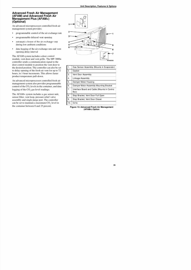
8/12/2019 Termo_King_Magnum_manual.pdf
http://slidepdf.com/reader/full/termokingmagnummanualpdf 35/194
Advanced Fresh Air Management(AFAM) and Advanced Fresh AirManagement Plus (AFAM+)(Optional)
An advanced microprocessor controlled fresh air
management system provides:
• programmable control of the air exchange rate
• programmable delayed vent opening
• automatic closure of the air exchange vent
during low ambient conditions
• data logging of the air exchange rate and vent
opening delay interval
The AFAM system includes a door control
module, vent door and vent grille. The MP-3000a
controller sends a communication signal to the
door control module to position the vent door to
the desired position. The controller can also be set
to delay opening of the fresh air vent for up to 72
hours, in 1-hour increments. This allows faster
product temperature pull-down.
An advanced microprocessor controlled fresh air
management system also provides programmable
control of the CO2 levels in the container, and data
logging of the CO2 gas level readings.
The AFAM+ system includes a gas sensor unit,
sensor filter, vent loop, pressure relief valve
assembly and single purge port. The controller
can be set to maintain a maximum CO2 level in
the container between 0 and 25 percent.
1. Gas Sensor Assembly (Mounts in Evaporator)
2. Gasket
3. Vent Door Assembly
4. Linkage Assembly
5. Damper Motor Housing
6. Damper Motor Assembly Mounting Bracket
7. Interface Board and Cable (Mounts in ControlBox)
8. Stop Bracket, Vent Door Full Open
9. Stop Bracket, Vent Door Closed
10. Grille
Figure 13: Advanced Fresh Air Management
(AFAM+) Option
AXA0235
1
2
4
3
56
1
9
8
7
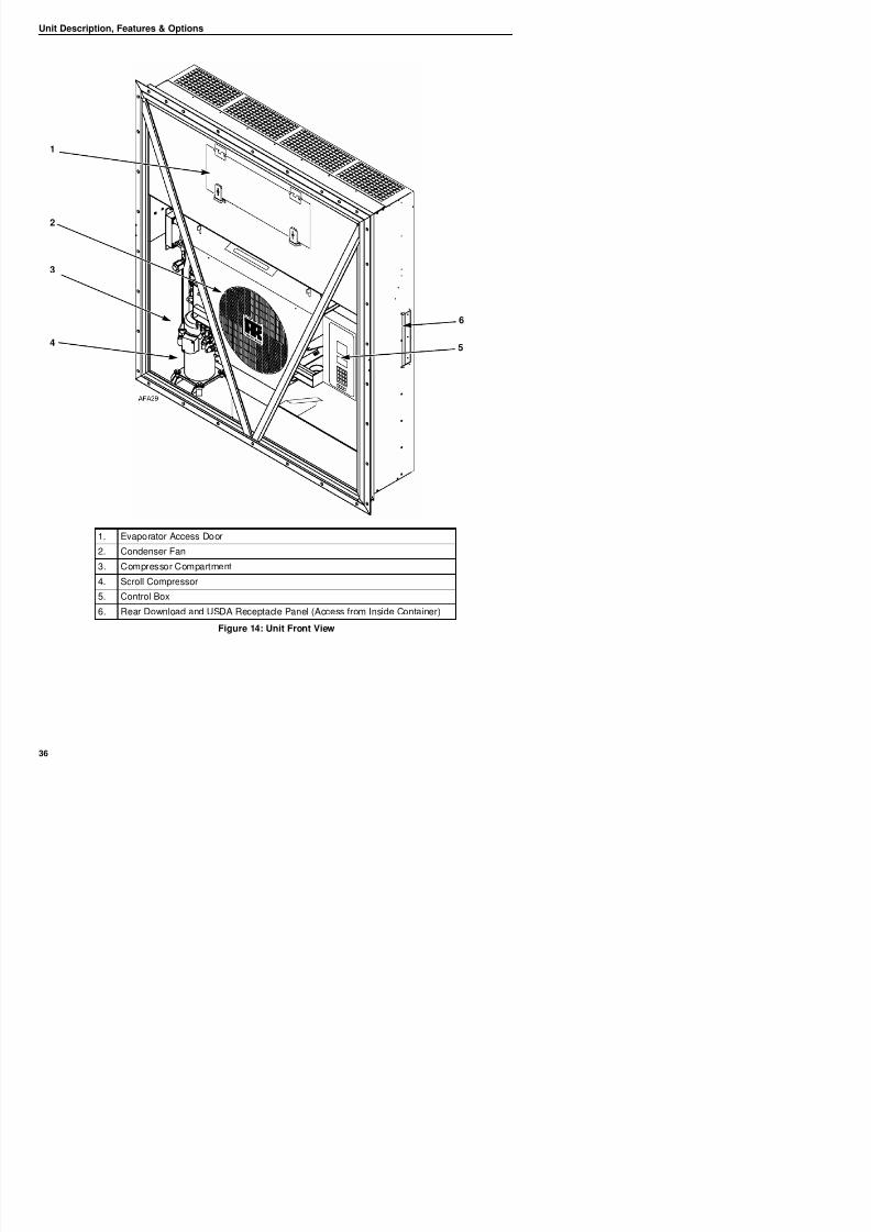
8/12/2019 Termo_King_Magnum_manual.pdf
http://slidepdf.com/reader/full/termokingmagnummanualpdf 36/194
Unit Description, Features & Options
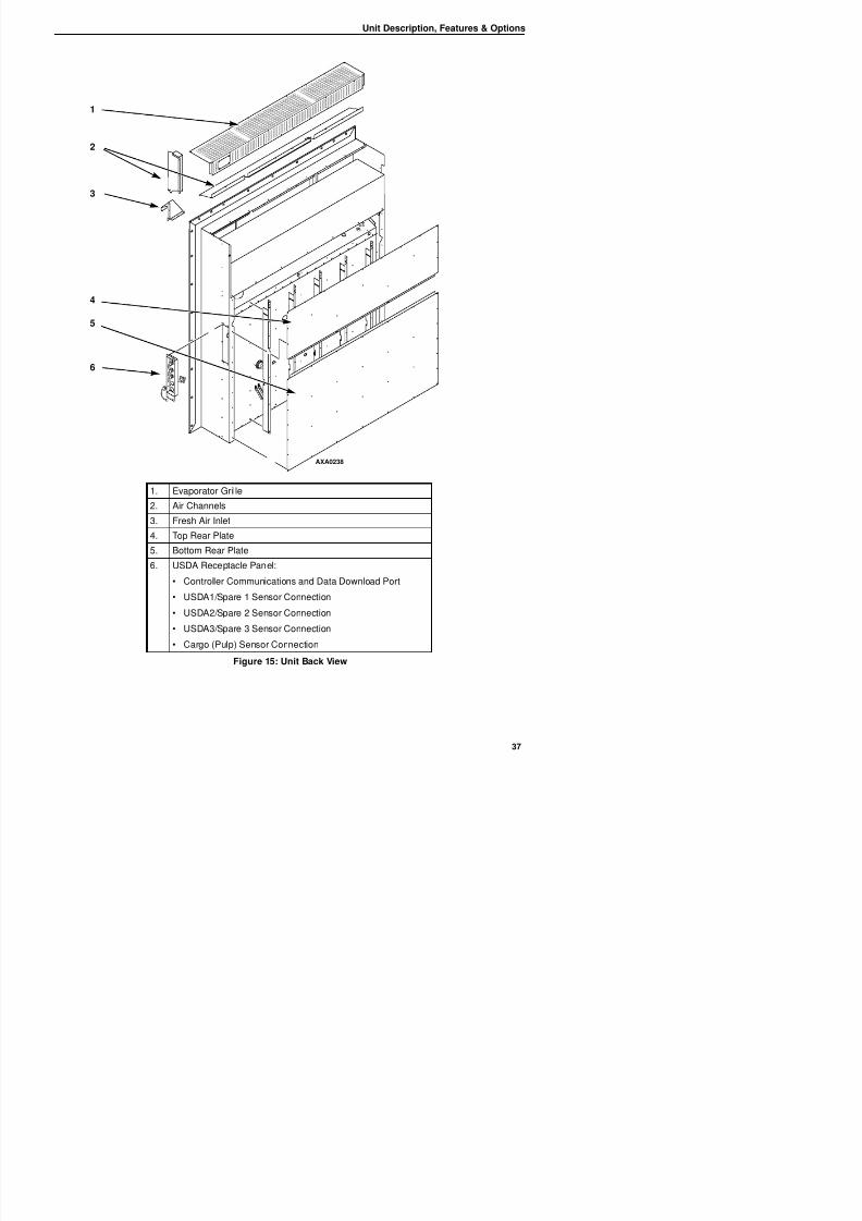
8/12/2019 Termo_King_Magnum_manual.pdf
http://slidepdf.com/reader/full/termokingmagnummanualpdf 37/194
AXA0238
1
2
4
5
6
3
1. Evaporator Grille2. Air Channels
3. Fresh Air Inlet
4. Top Rear Plate
5. Bottom Rear Plate
Unit Description, Features & Options
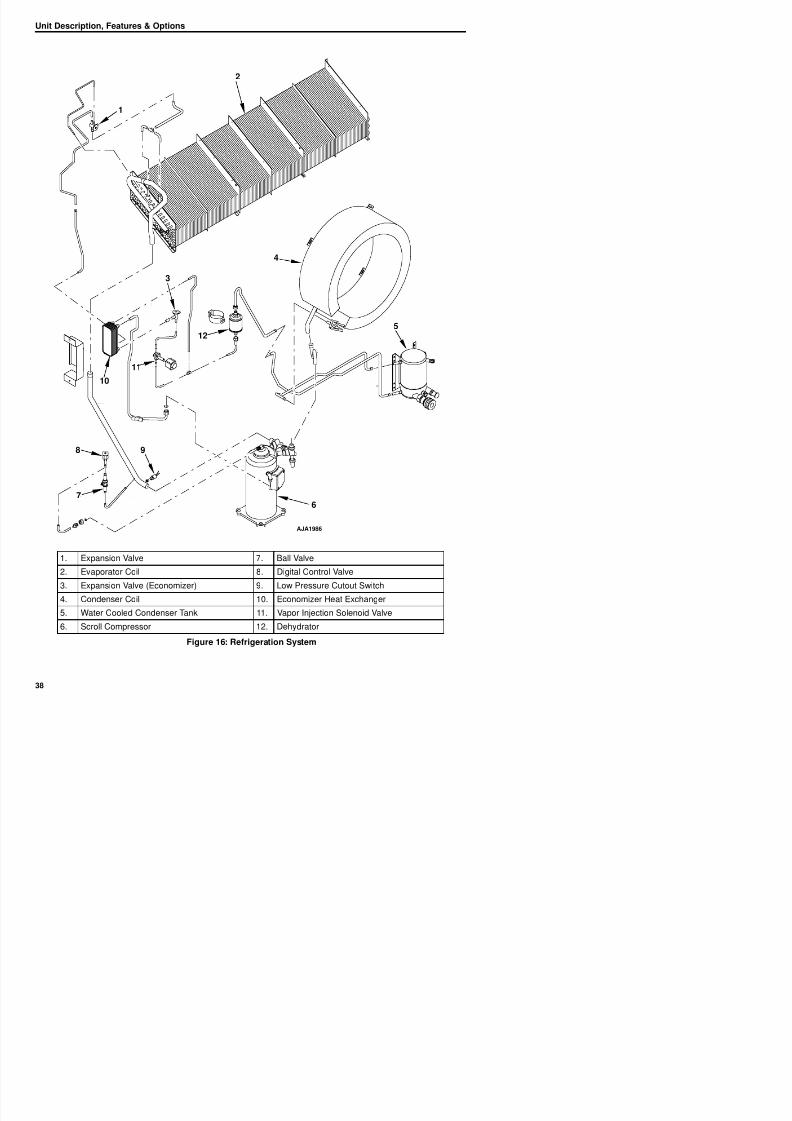
8/12/2019 Termo_King_Magnum_manual.pdf
http://slidepdf.com/reader/full/termokingmagnummanualpdf 38/194
2
1
10
8 9
6
4
12
3
11
5
7
Unit Description, Features & Options
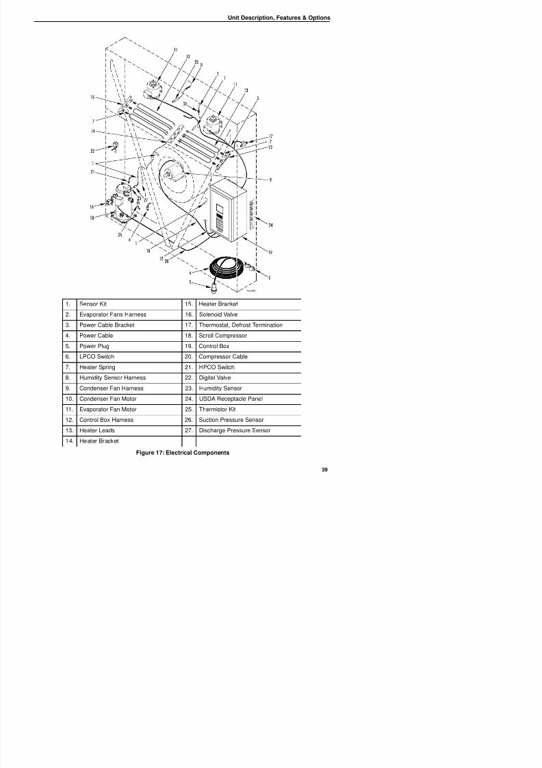
8/12/2019 Termo_King_Magnum_manual.pdf
http://slidepdf.com/reader/full/termokingmagnummanualpdf 39/194
1. Sensor Kit 15. Heater Bracket
2. Evaporator Fans Harness 16. Solenoid Valve
3. Power Cable Bracket 17. Thermostat, Defrost Termination
4. Power Cable 18. Scroll Compressor
5. Power Plug 19. Control Box
Unit Description, Features & Options

8/12/2019 Termo_King_Magnum_manual.pdf
http://slidepdf.com/reader/full/termokingmagnummanualpdf 40/194
Controller Description
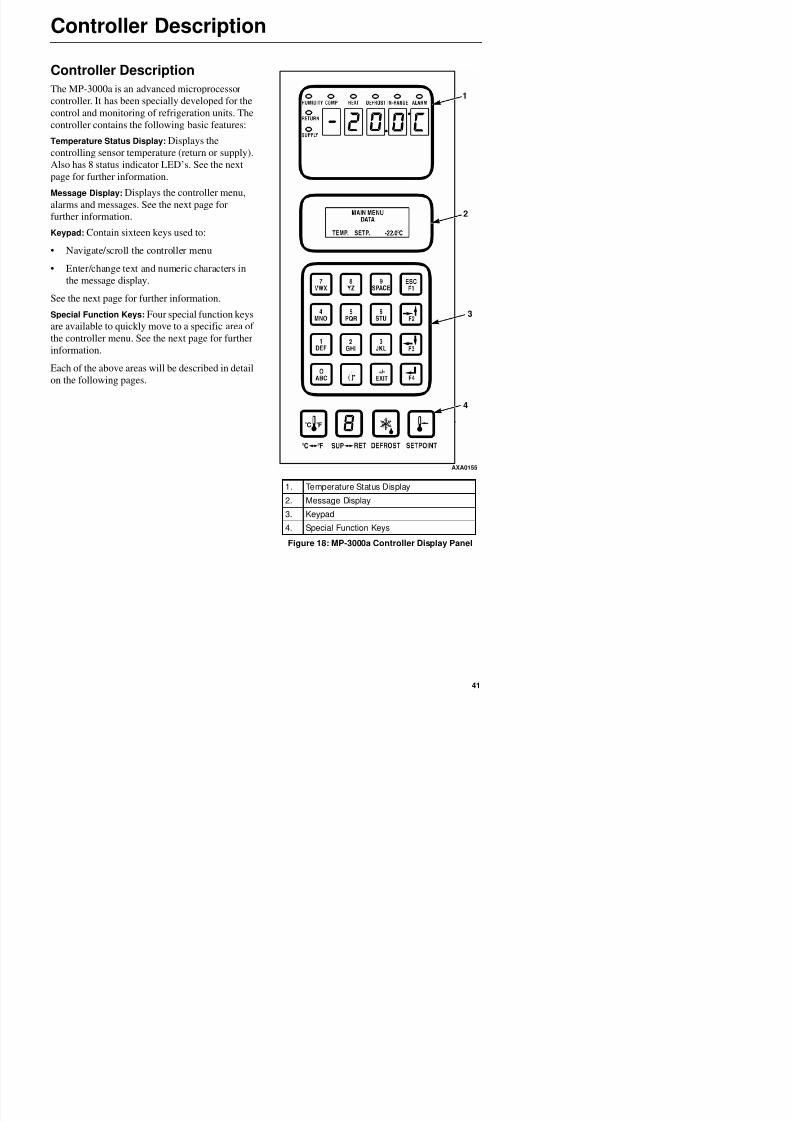
8/12/2019 Termo_King_Magnum_manual.pdf
http://slidepdf.com/reader/full/termokingmagnummanualpdf 41/194
Controller Description
The MP-3000a is an advanced microprocessor
controller. It has been specially developed for thecontrol and monitoring of refrigeration units. The
controller contains the following basic features:
Temperature Status Display: Displays the
controlling sensor temperature (return or supply).
Also has 8 status indicator LED’s. See the next
page for further information.
Message Display: Displays the controller menu,
alarms and messages. See the next page for
further information.
Keypad: Contain sixteen keys used to:
• Navigate/scroll the controller menu
• Enter/change text and numeric characters in
the message display.
See the next page for further information.
Special Function Keys: Four special function keys
are available to quickly move to a specific area of
the controller menu. See the next page for further
information.
Each of the above areas will be described in detailon the following pages.
1. Temperature Status Display
2. Message Display
AXA0155
1
2
3
4
Controller Description
T t St t Di l M Di l
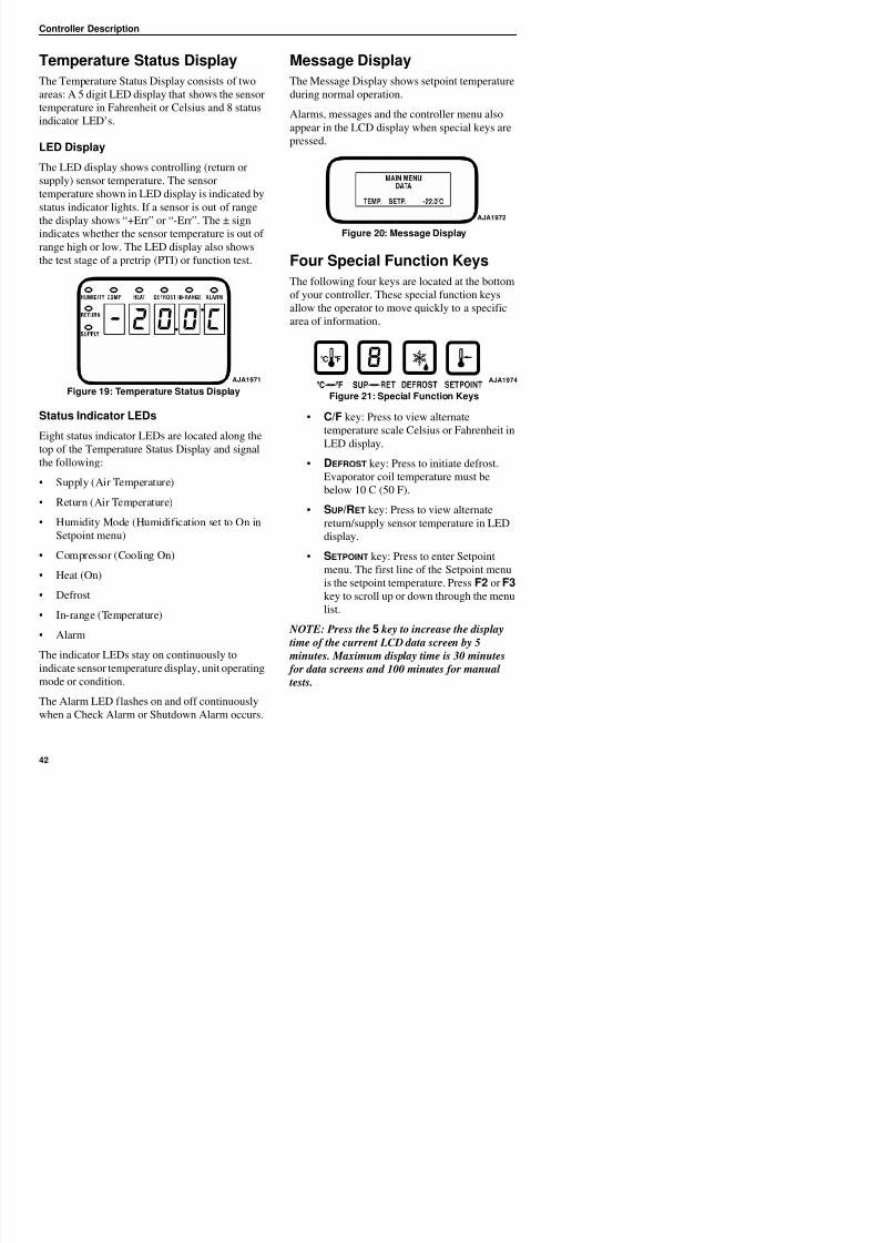
8/12/2019 Termo_King_Magnum_manual.pdf
http://slidepdf.com/reader/full/termokingmagnummanualpdf 42/194
Temperature Status Display
The Temperature Status Display consists of two
areas: A 5 digit LED display that shows the sensor
temperature in Fahrenheit or Celsius and 8 statusindicator LED’s.
LED Display
The LED display shows controlling (return or
supply) sensor temperature. The sensor
temperature shown in LED display is indicated by
status indicator lights. If a sensor is out of rangethe display shows “+Err” or “-Err”. The ± sign
indicates whether the sensor temperature is out of
range high or low. The LED display also shows
the test stage of a pretrip (PTI) or function test.
Figure 19: Temperature Status Display
Status Indicator LEDs
Eight status indicator LEDs are located along the
top of the Temperature Status Display and signal
the following:
• Supply (Air Temperature)
• Return (Air Temperature)
• Humidity Mode (Humidification set to On in
Setpoint menu)
• Compressor (Cooling On)
Message Display
The Message Display shows setpoint temperature
during normal operation.
Alarms, messages and the controller menu also
appear in the LCD display when special keys are
pressed.
Figure 20: Message Display
Four Special Function Keys
The following four keys are located at the bottom
of your controller. These special function keys
allow the operator to move quickly to a specificarea of information.
Figure 21: Special Function Keys
• C/F key: Press to view alternate
temperature scale Celsius or Fahrenheit in
LED display.
• DEFROST key: Press to initiate defrost.
Evaporator coil temperature must be
below 10 C (50 F).
• SUP/RET key: Press to view alternate
return/supply sensor temperature in LED
display.
• SETPOINT key: Press to enter Setpoint
AJA1971
AJA1972
AJA1974
Controller Description
Keypad • Data logger Menu
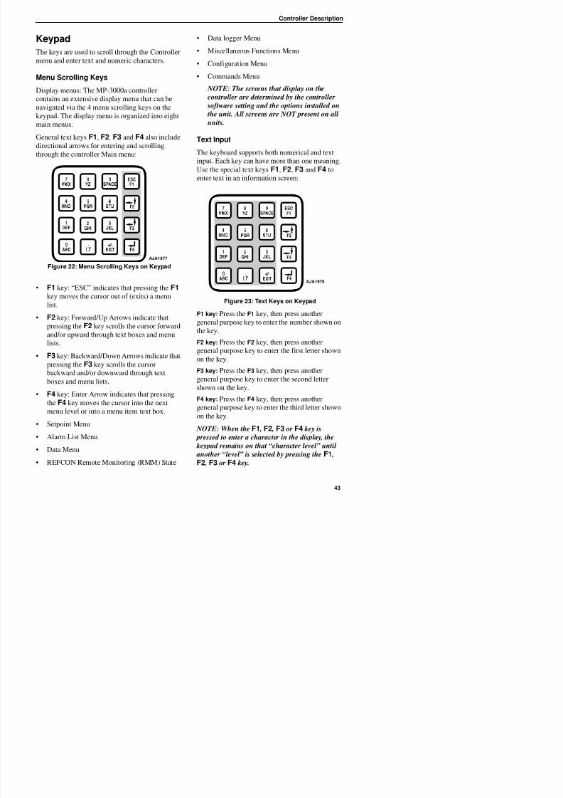
8/12/2019 Termo_King_Magnum_manual.pdf
http://slidepdf.com/reader/full/termokingmagnummanualpdf 43/194
Keypad
The keys are used to scroll through the Controller
menu and enter text and numeric characters.
Menu Scrolling Keys
Display menus: The MP-3000a controller
contains an extensive display menu that can be
navigated via the 4 menu scrolling keys on the
keypad. The display menu is organized into eight
main menus.
General text keys F1, F2, F3 and F4 also include
directional arrows for entering and scrolling
through the controller Main menu:
Figure 22: Menu Scrolling Keys on Keypad
• F1 key: “ESC” indicates that pressing the F1
key moves the cursor out of (exits) a menu
list.
• F2 key: Forward/Up Arrows indicate that
pressing the F2 key scrolls the cursor forwardand/or upward through text boxes and menu
lists.
• F3 key: Backward/Down Arrows indicate that
i h F3 k ll h
• Data logger Menu
• Miscellaneous Functions Menu
• Configuration Menu
• Commands Menu
NOTE: The screens that display on the
controller are determined by the controller
software setting and the options installed on
the unit. All screens are NOT present on all
units.
Text Input
The keyboard supports both numerical and text
input. Each key can have more than one meaning.
Use the special text keys F1, F2, F3 and F4 to
enter text in an information screen:
Figure 23: Text Keys on Keypad
F1 key: Press the F1 key, then press another
general purpose key to enter the number shown onthe key.
F2 key: Press the F2 key, then press another
general purpose key to enter the first letter shown
on the key.
AJA1977
AJA1978
Controller Description
Text Input Example
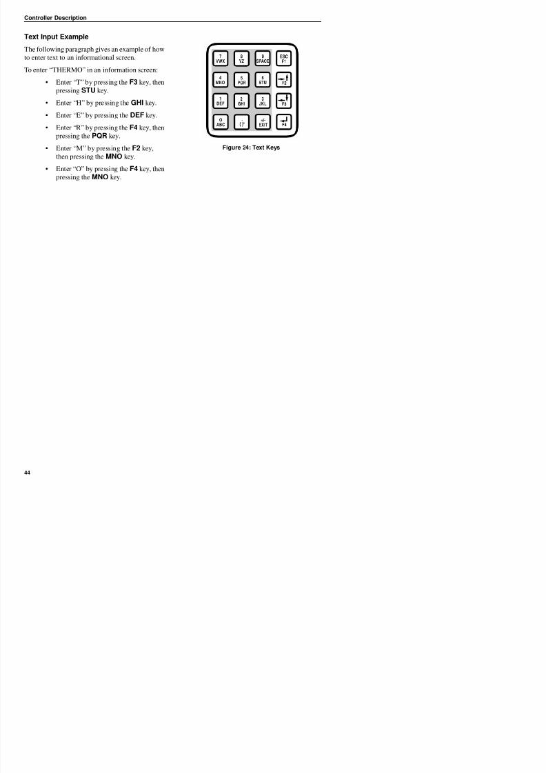
8/12/2019 Termo_King_Magnum_manual.pdf
http://slidepdf.com/reader/full/termokingmagnummanualpdf 44/194
Text Input Example
The following paragraph gives an example of how
to enter text to an informational screen.
To enter “THERMO” in an information screen:
• Enter “T” by pressing the F3 key, then
pressing STU key.
• Enter “H” by pressing the GHI key.
• Enter “E” by pressing the DEF key.
• Enter “R” by pressing the F4 key, thenpressing the PQR key.
• Enter “M” by pressing the F2 key,
then pressing the MNO key.
• Enter “O” by pressing the F4 key, then
pressing the MNO key.
Figure 24: Text Keys
Navigating the Controller Operating Menu
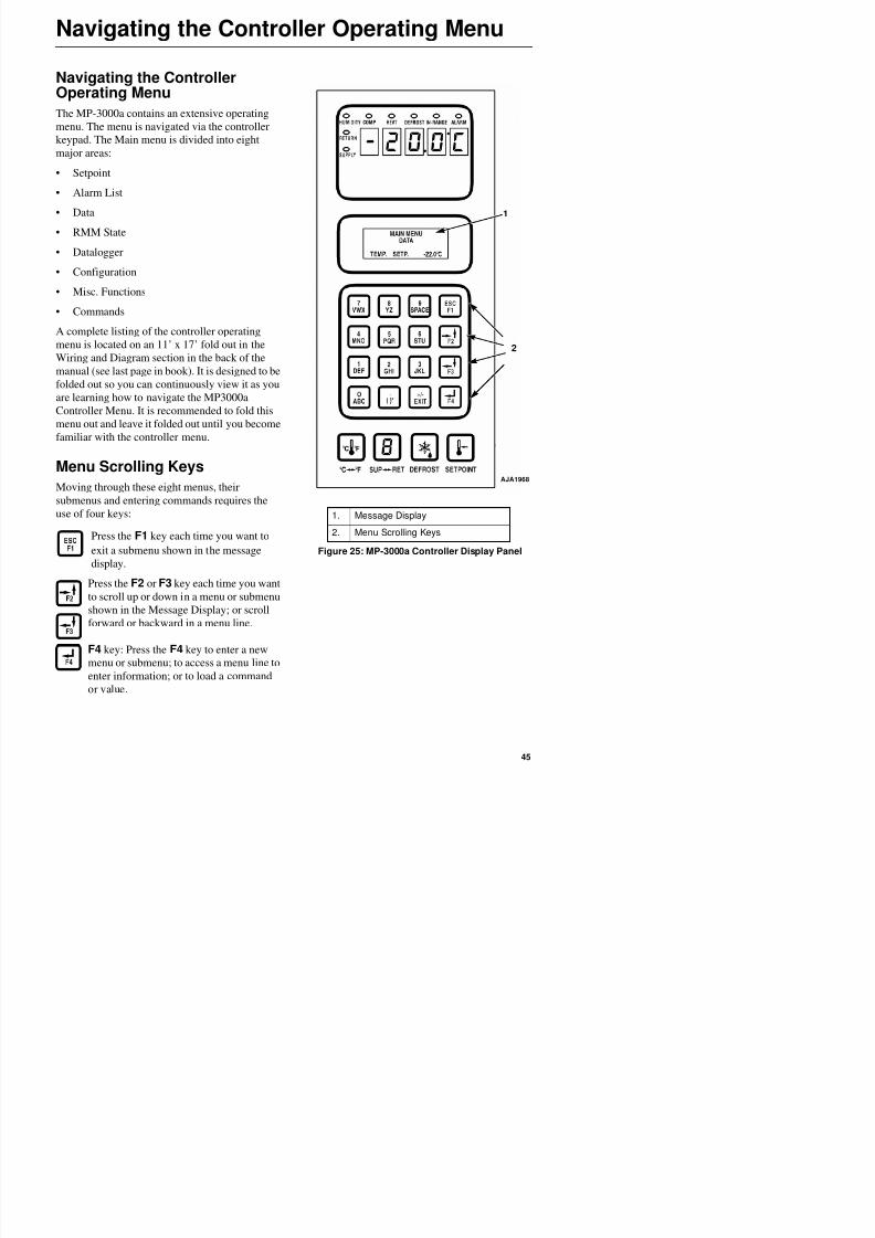
8/12/2019 Termo_King_Magnum_manual.pdf
http://slidepdf.com/reader/full/termokingmagnummanualpdf 45/194
Navigating the ControllerOperating Menu
The MP-3000a contains an extensive operating
menu. The menu is navigated via the controller
keypad. The Main menu is divided into eight
major areas:
• Setpoint
• Alarm List
• Data
• RMM State
• Datalogger
• Configuration
• Misc. Functions
• Commands
A complete listing of the controller operating
menu is located on an 11’ x 17’ fold out in the
Wiring and Diagram section in the back of the
manual (see last page in book). It is designed to be
folded out so you can continuously view it as you
are learning how to navigate the MP3000a
Controller Menu. It is recommended to fold this
menu out and leave it folded out until you become
familiar with the controller menu.
Menu Scrolling Keys
Moving through these eight menus, their
submenus and entering commands requires theuse of four keys:
Press the F1 key each time you want to
exit a submenu shown in the message
di l
1. Message Display
2. Menu Scrolling Keys
Figure 25: MP-3000a Controller Display Panel
AJA1968
1
2
Navigating the Controller Operating Menu
1. Display menus: The MP-3000a controller • Data logger Menu: Menu screens in this
8/12/2019 Termo_King_Magnum_manual.pdf
http://slidepdf.com/reader/full/termokingmagnummanualpdf 46/194
1. Display menus: The MP 3000a controller
contains an extensive display menu that can be
navigated via keypad. The display menu is
organized into eight main menus:
NOTE: The screens that display on the
controller are determined by the controller
software setting and the options installed on
the unit. All screens are NOT present on all
units.
• Setpoint Menu: Menu screens in this
group are used to enter the temperaturesetpoint and set the Economy mode.
Setpoint menu option functions include:
set Bulb mode or dehumidify operation
and enter humidity setpoint, set AFAM,
set AFAM delay, set AFAM rate, set O2
Minimum, set CO2 Maximum and
OPTI-SET.
• Alarm List Menu: Menu screens in this
group display a list of alarm code(s).
• Data Menu: Menu screens in this group
are used to display unit operating
information including sensor
temperatures, voltage, current and
frequency information.
• REFCON Remote Monitoring (RMM)
State: Menu screen show current remote
monitoring state (Offline, Zombie or
On-line).
Data logger Menu: Menu screens in this
group display temperature log, event log,
set log time and PTI log.
• Configuration Menu: Menu screens in thisgroup display refrigerant type, in-range
setting, container ID, contrast (screen),
language, unit type, reefer type, AFAM
option, evaporator type, condenser type,
USDA type, AFAM units and other unit
settings.
• Miscellaneous Functions Menu: Menuscreens in this group display date/time,
C/F, cargo data, program version and run
time (hourmeters) information.
• Commands Menu: Menu screens in this
group are used to activate pretrip (PTI)
tests, function tests, manual function tests,
and power management.A complete listing of the controller operating
menu is located on an 11’ x 17’ fold out in the
Wiring and Diagram section in the back of the
manual (see last page in book). It is designed to be
folded out so you can continuously view it as you
are learning how to navigate the MP3000a
Controller Menu. It is recommended to fold thismenu out and leave it folded out until you become
familiar with the controller menu.
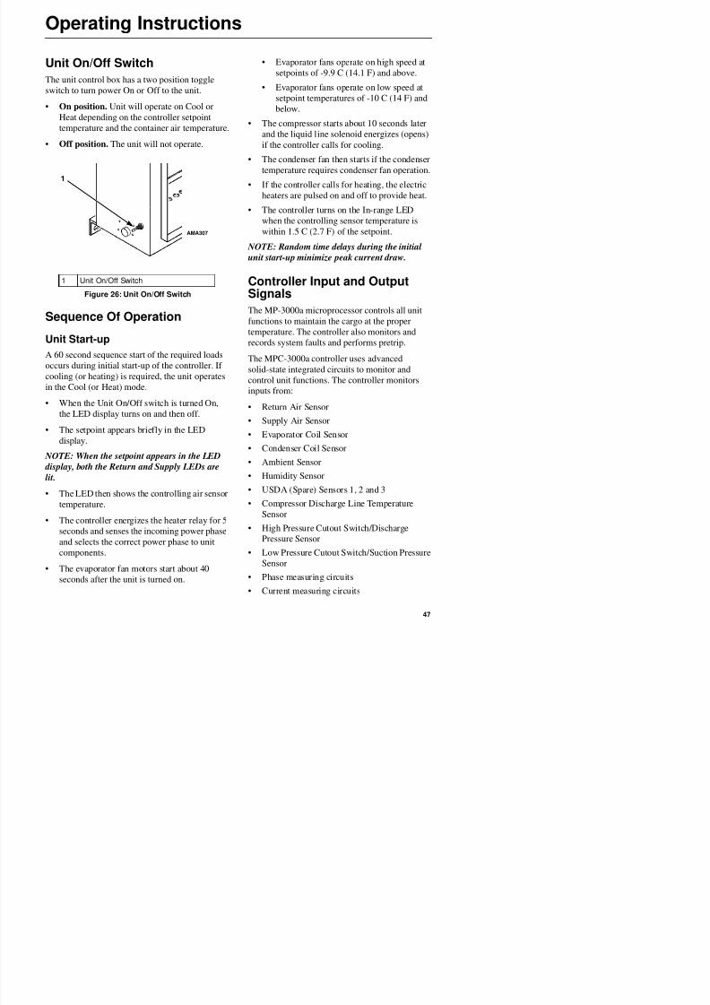
8/12/2019 Termo_King_Magnum_manual.pdf
http://slidepdf.com/reader/full/termokingmagnummanualpdf 47/194
Operating Instructions
• Voltage measuring circuits Initiating a Manual
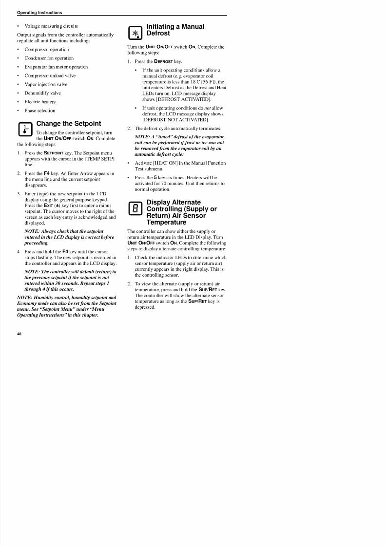
8/12/2019 Termo_King_Magnum_manual.pdf
http://slidepdf.com/reader/full/termokingmagnummanualpdf 48/194
Output signals from the controller automatically
regulate all unit functions including:
• Compressor operation
• Condenser fan operation
• Evaporator fan motor operation
• Compressor unload valve
• Vapor injection valve
• Dehumidify valve
• Electric heaters
• Phase selection
Change the Setpoint
To change the controller setpoint, turn
the UNIT ON/OFF switch ON. Complete
the following steps:
1. Press the SETPOINT key. The Setpoint menu
appears with the cursor in the [TEMP SETP]
line.
2. Press the F4 key. An Enter Arrow appears in
the menu line and the current setpointdisappears.
3. Enter (type) the new setpoint in the LCD
display using the general purpose keypad.
Press the EXIT (±) key first to enter a minus
setpoint. The cursor moves to the right of the
screen as each key entry is acknowledged and
displayed.
NOTE: Always check that the setpoint
entered in the LCD display is correct before
proceeding.
t at g a a uaDefrost
Turn the UNIT ON/OFF switch ON. Complete thefollowing steps:
1. Press the DEFROST key.
• If the unit operating conditions allow a
manual defrost (e.g. evaporator coil
temperature is less than 18 C [56 F]), the
unit enters Defrost as the Defrost and Heat
LEDs turn on. LCD message displayshows [DEFROST ACTIVATED].
• If unit operating conditions do not allow
defrost, the LCD message display shows
[DEFROST NOT ACTIVATED].
2. The defrost cycle automatically terminates.
NOTE: A “timed” defrost of the evaporator coil can be performed if frost or ice can not
be removed from the evaporator coil by an
automatic defrost cycle:
• Activate [HEAT ON] in the Manual Function
Test submenu.
• Press the 5 key six times. Heaters will beactivated for 70 minutes. Unit then returns to
normal operation.
Display AlternateControlling (Supply orReturn) Air Sensor
TemperatureThe controller can show either the supply or
return air temperature in the LED Display. Turn
UNIT ON/OFF switch ON. Complete the following
t t di l lt t t lli t t
Operating Instructions
3. The display then returns to controlling sensor
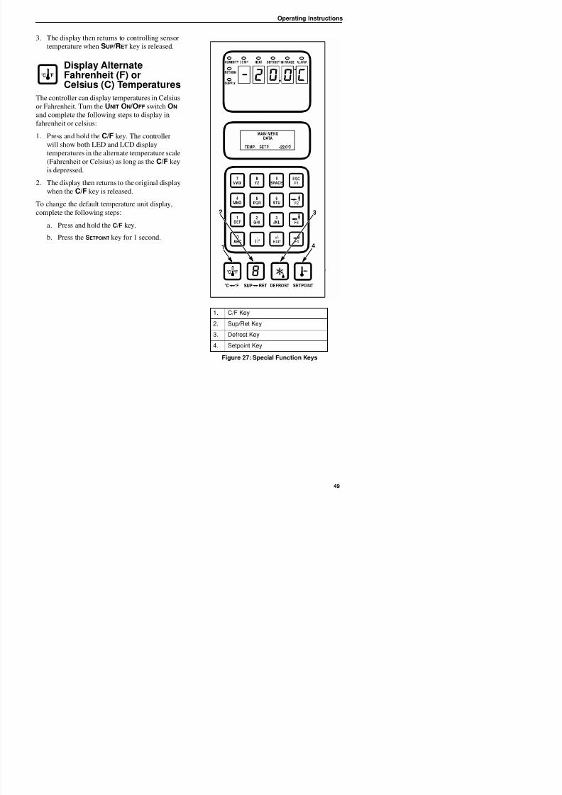
8/12/2019 Termo_King_Magnum_manual.pdf
http://slidepdf.com/reader/full/termokingmagnummanualpdf 49/194
temperature when SUP/RET key is released.
Display AlternateFahrenheit (F) orCelsius (C) Temperatures
The controller can display temperatures in Celsius
or Fahrenheit. Turn the UNIT ON/OFF switch ON
and complete the following steps to display in
fahrenheit or celsius:
1. Press and hold the C/F key. The controllerwill show both LED and LCD display
temperatures in the alternate temperature scale
(Fahrenheit or Celsius) as long as the C/F key
is depressed.
2. The display then returns to the original display
when the C/F key is released.
To change the default temperature unit display,
complete the following steps:
a. Press and hold the C/F key.
b. Press the SETPOINT key for 1 second.
1. C/F Key
2. Sup/Ret Key
3. Defrost Key
4. Setpoint Key
Figure 27: Special Function Keys
2
1
3
4
Operating Instructions
Setpoint MenuNOTE: All screens are NOT
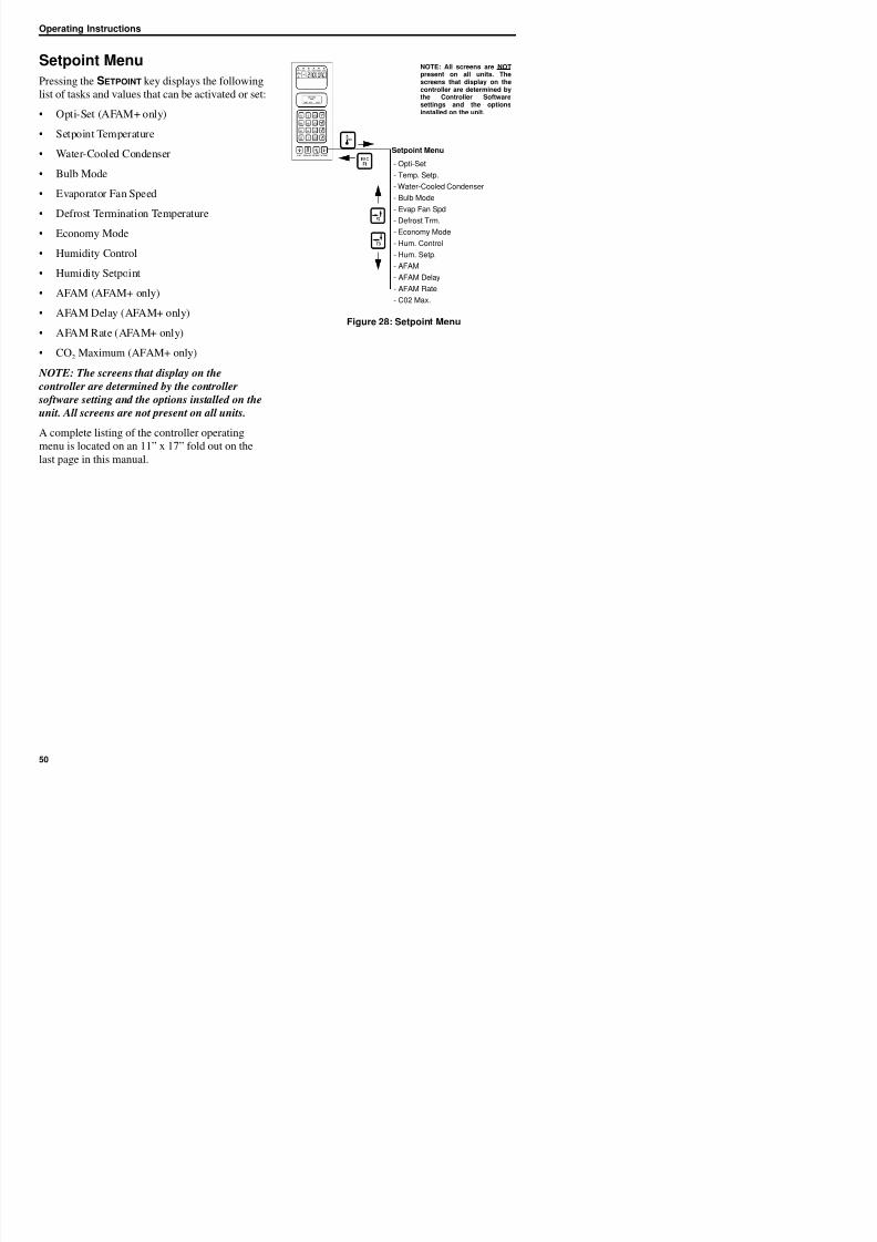
8/12/2019 Termo_King_Magnum_manual.pdf
http://slidepdf.com/reader/full/termokingmagnummanualpdf 50/194
p
Pressing the SETPOINT key displays the following
list of tasks and values that can be activated or set:
• Opti-Set (AFAM+ only)
• Setpoint Temperature
• Water-Cooled Condenser
• Bulb Mode
• Evaporator Fan Speed
• Defrost Termination Temperature
• Economy Mode
• Humidity Control
• Humidity Setpoint
• AFAM (AFAM+ only)
• AFAM Delay (AFAM+ only)
• AFAM Rate (AFAM+ only)
• CO2 Maximum (AFAM+ only)
NOTE: The screens that display on the
controller are determined by the controller
software setting and the options installed on the
unit. All screens are not present on all units.
A complete listing of the controller operating
menu is located on an 11” x 17” fold out on the
last page in this manual.
Figure 28: Setpoint Menu
Setpoint Menu
- Opti-Set
- Temp. Setp.
- Water-Cooled Condenser
- Bulb Mode
- Evap Fan Spd- Defrost Trm.
- Economy Mode
- Hum. Control
- Hum. Setp.
- AFAM
- AFAM Delay
- AFAM Rate
- C02 Max.
NOTE: All screens are NOTpresent on all units. Thescreens that display on thecontroller are determined bythe Controller Softwaresettings and the options
installed on the unit.
Operating Instructions
Change the Setpoint Temperature • [FLOW HIGH]: Evaporator fans operate
ti l hi h d
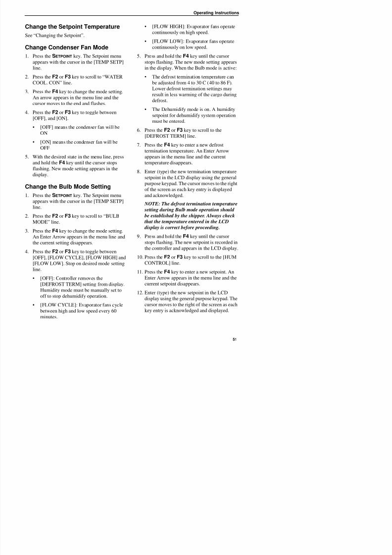
8/12/2019 Termo_King_Magnum_manual.pdf
http://slidepdf.com/reader/full/termokingmagnummanualpdf 51/194
See “Changing the Setpoint”.
Change Condenser Fan Mode1. Press the SETPOINT key. The Setpoint menu
appears with the cursor in the [TEMP SETP]
line.
2. Press the F2 or F3 key to scroll to “WATER
COOL. CON” line.
3. Press the F4 key to change the mode setting.An arrow appears in the menu line and the
cursor moves to the end and flashes.
4. Press the F2 or F3 key to toggle between
[OFF], and [ON].
• [OFF] means the condenser fan will be
ON
• [ON] means the condenser fan will be
OFF
5. With the desired state in the menu line, press
and hold the F4 key until the cursor stops
flashing. New mode setting appears in the
display.
Change the Bulb Mode Setting
1. Press the SETPOINT key. The Setpoint menu
appears with the cursor in the [TEMP SETP]
line.
2. Press the F2 or F3 key to scroll to “BULB
MODE” line.
3. Press the F4 key to change the mode setting.
An Enter Arrow appears in the menu line and
the current setting disappears.
4 Press the F2 or F3 key to toggle between
continuously on high speed.
• [FLOW LOW]: Evaporator fans operate
continuously on low speed.5. Press and hold the F4 key until the cursor
stops flashing. The new mode setting appears
in the display. When the Bulb mode is active:
• The defrost termination temperature can
be adjusted from 4 to 30 C (40 to 86 F).
Lower defrost termination settings may
result in less warming of the cargo duringdefrost.
• The Dehumidify mode is on. A humidity
setpoint for dehumidify system operation
must be entered.
6. Press the F2 or F3 key to scroll to the
[DEFROST TERM] line.7. Press the F4 key to enter a new defrost
termination temperature. An Enter Arrow
appears in the menu line and the current
temperature disappears.
8. Enter (type) the new termination temperature
setpoint in the LCD display using the general
purpose keypad. The cursor moves to the rightof the screen as each key entry is displayed
and acknowledged.
NOTE: The defrost termination temperature
setting during Bulb mode operation should
be established by the shipper. Always check
that the temperature entered in the LCD
display is correct before proceeding.
9. Press and hold the F4 key until the cursor
stops flashing. The new setpoint is recorded in
the controller and appears in the LCD display.
Operating Instructions
NOTE: The humidity setpoint should be
established by the shipper Always check thatNOTE: All screens are NOT
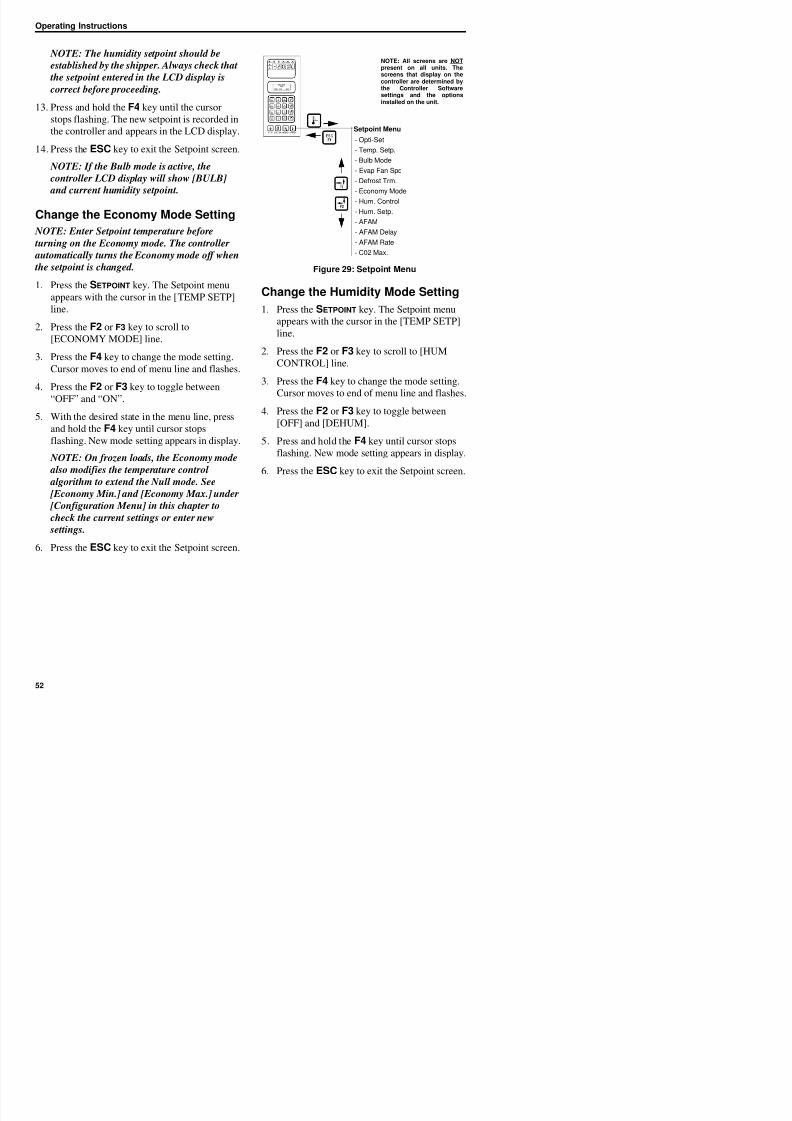
8/12/2019 Termo_King_Magnum_manual.pdf
http://slidepdf.com/reader/full/termokingmagnummanualpdf 52/194
established by the shipper. Always check that
the setpoint entered in the LCD display is
correct before proceeding.
13. Press and hold the F4 key until the cursor
stops flashing. The new setpoint is recorded in
the controller and appears in the LCD display.
14. Press the ESC key to exit the Setpoint screen.
NOTE: If the Bulb mode is active, the
controller LCD display will show [BULB]
and current humidity setpoint.
Change the Economy Mode Setting
NOTE: Enter Setpoint temperature before
turning on the Economy mode. The controller
automatically turns the Economy mode off when
the setpoint is changed.
1. Press the SETPOINT key. The Setpoint menu
appears with the cursor in the [TEMP SETP]
line.
2. Press the F2 or F3 key to scroll to
[ECONOMY MODE] line.
3. Press the F4 key to change the mode setting.
Cursor moves to end of menu line and flashes.
4. Press the F2 or F3 key to toggle between
“OFF” and “ON”.
5. With the desired state in the menu line, press
and hold the F4 key until cursor stops
flashing. New mode setting appears in display.
NOTE: On frozen loads, the Economy mode also modifies the temperature control
algorithm to extend the Null mode. See
[Economy Min.] and [Economy Max.] under
[Configuration Menu] in this chapter to
Figure 29: Setpoint Menu
Change the Humidity Mode Setting
1. Press the SETPOINT key. The Setpoint menu
appears with the cursor in the [TEMP SETP]
line.
2. Press the F2 or F3 key to scroll to [HUM
CONTROL] line.3. Press the F4 key to change the mode setting.
Cursor moves to end of menu line and flashes.
4. Press the F2 or F3 key to toggle between
[OFF] and [DEHUM].
5. Press and hold the F4 key until cursor stops
flashing. New mode setting appears in display.6. Press the ESC key to exit the Setpoint screen.
Setpoint Menu
- Opti-Set
- Temp. Setp.
- Bulb Mode
- Evap Fan Spd
- Defrost Trm.
- Economy Mode
- Hum. Control
- Hum. Setp.
- AFAM
- AFAM Delay
- AFAM Rate
- C02 Max.
present on all units. Thescreens that display on thecontroller are determined bythe Controller Softwaresettings and the options
installed on the unit.
Operating Instructions
Change the Humidity SetpointNOTE: All screens are NOTpresent on all units The
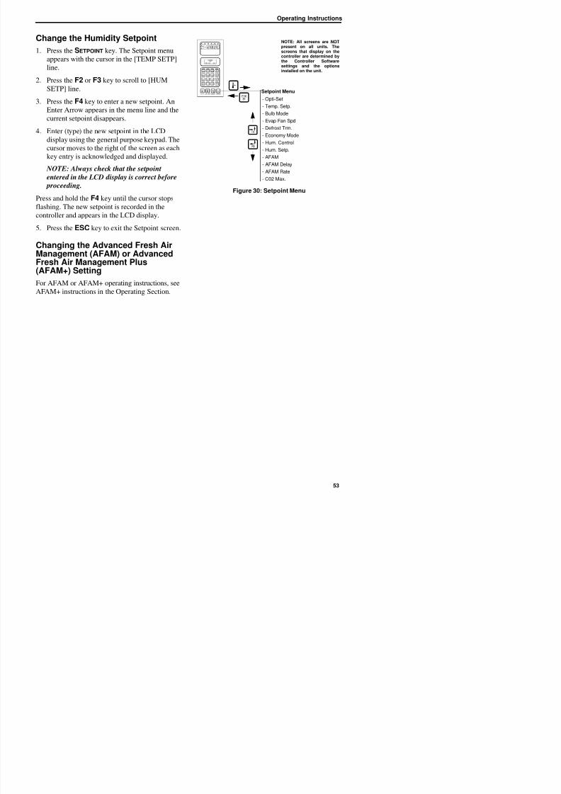
8/12/2019 Termo_King_Magnum_manual.pdf
http://slidepdf.com/reader/full/termokingmagnummanualpdf 53/194
1. Press the SETPOINT key. The Setpoint menu
appears with the cursor in the [TEMP SETP]
line.2. Press the F2 or F3 key to scroll to [HUM
SETP] line.
3. Press the F4 key to enter a new setpoint. An
Enter Arrow appears in the menu line and the
current setpoint disappears.
4. Enter (type) the new setpoint in the LCDdisplay using the general purpose keypad. The
cursor moves to the right of the screen as each
key entry is acknowledged and displayed.
NOTE: Always check that the setpoint
entered in the LCD display is correct before
proceeding.
Press and hold the F4 key until the cursor stopsflashing. The new setpoint is recorded in the
controller and appears in the LCD display.
5. Press the ESC key to exit the Setpoint screen.
Changing the Advanced Fresh AirManagement (AFAM) or Advanced
Fresh Air Management Plus(AFAM+) Setting
For AFAM or AFAM+ operating instructions, see
AFAM+ instructions in the Operating Section.
Figure 30: Setpoint Menu
Setpoint Menu
- Opti-Set
- Temp. Setp.
- Bulb Mode
- Evap Fan Spd
- Defrost Trm.
- Economy Mode
- Hum. Control
- Hum. Setp.
- AFAM
- AFAM Delay
- AFAM Rate
- C02 Max.
present on all units. Thescreens that display on thecontroller are determined bythe Controller Softwaresettings and the options
installed on the unit.
Operating Instructions
Alarms Menu
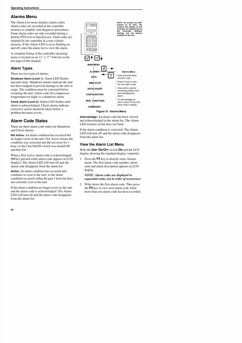
8/12/2019 Termo_King_Magnum_manual.pdf
http://slidepdf.com/reader/full/termokingmagnummanualpdf 54/194
The Alarm List menu displays alarm codes.
Alarm codes are recorded in the controller
memory to simplify unit diagnosis procedures.Some alarm codes are only recorded during a
pretrip (PTI) test or function test. Fault codes are
retained by the controller in a non-volatile
memory. If the Alarm LED is on or flashing on
and off, enter the alarm list to view the alarm.
A complete listing of the controller operating
menu is located on an 11” x 17” fold out on thelast page of this manual.
Alarm Types
There are two types of alarms:
Shutdown Alarm (Level 1): Alarm LED flashes
and unit stops. Shutdown alarms indicate the unit
has been stopped to prevent damage to the unit orcargo. The condition must be corrected before
restarting the unit. Alarm code 56 (compressor
temperature too high) is a shutdown alarm.
Check Alarm (Level 2): Alarm LED flashes until
alarm is acknowledged. Check alarms indicate
corrective action should be taken before a
problem becomes severe.
Alarm Code States
There are three alarm code states for Shutdown
and Check alarms:
Not Active: An alarm condition has occurred but
no longer exists in the unit. Not Active means thecondition was corrected and did not recur for 1
hour; or the Unit On/Off switch was turned Off
and then On.
When a Not Active alarm code is acknowledged
Figure 31: Alarms MenuAcknowledge: An alarm code has been viewed
and acknowledged in the alarm list. The Alarm
LED remains on but does not flash.
If the alarm condition is corrected: The Alarm
LED will turn off and the alarm code disappears
from the alarm list.
View the Alarm List Menu
With the UNIT ON/OFF switch ON and the LCD
display showing the standard display (setpoint):
ALARMS Alarms Menu
• View and write down
all alarm code.
• Press F2 key to view
the next alarm code• Clear alarm code by
correcting problem and
acknowledging the
alarm.
• To acknowledge an
alarm, press F4 key with
alarm code in display.
MAIN MENU
DATA
RMM STATE
DATALOGGER
CONFIGURATION
MISC. FUNCTIONS
COMMANDS
NOTE: All screens are NOTpresent on all units. Thescreens that display on thecontroller are determined by
the Controller Softwaresettings and the optionsinstalled on the unit.
Operating Instructions
3. Repeat above step until all alarm codes have
been recorded. Press the F3 key to scroll
8/12/2019 Termo_King_Magnum_manual.pdf
http://slidepdf.com/reader/full/termokingmagnummanualpdf 55/194
been recorded. Press the F3 key to scroll
backward to return to a previous alarm code.
4. To clear all alarm codes from the current
display list and turn off the Alarm LED, all
problems must be corrected and the alarm
code “acknowledged” in the Alarm List menu.
5. To acknowledge an alarm, press F4 while
alarm code appears on screen. The alarm state
will change from Active or Not Active to
Acknowledge. If no key is pressed for 30seconds, the controller returns to previous
menu level or LCD Standard Display
NOTE: See detailed Alarm Code list complete
with corrective actions in the Diagnosing and
Troubleshooting Section in the back of the
manual.
Operating Instructions
Alarm List Alarm List (Continued)
Al
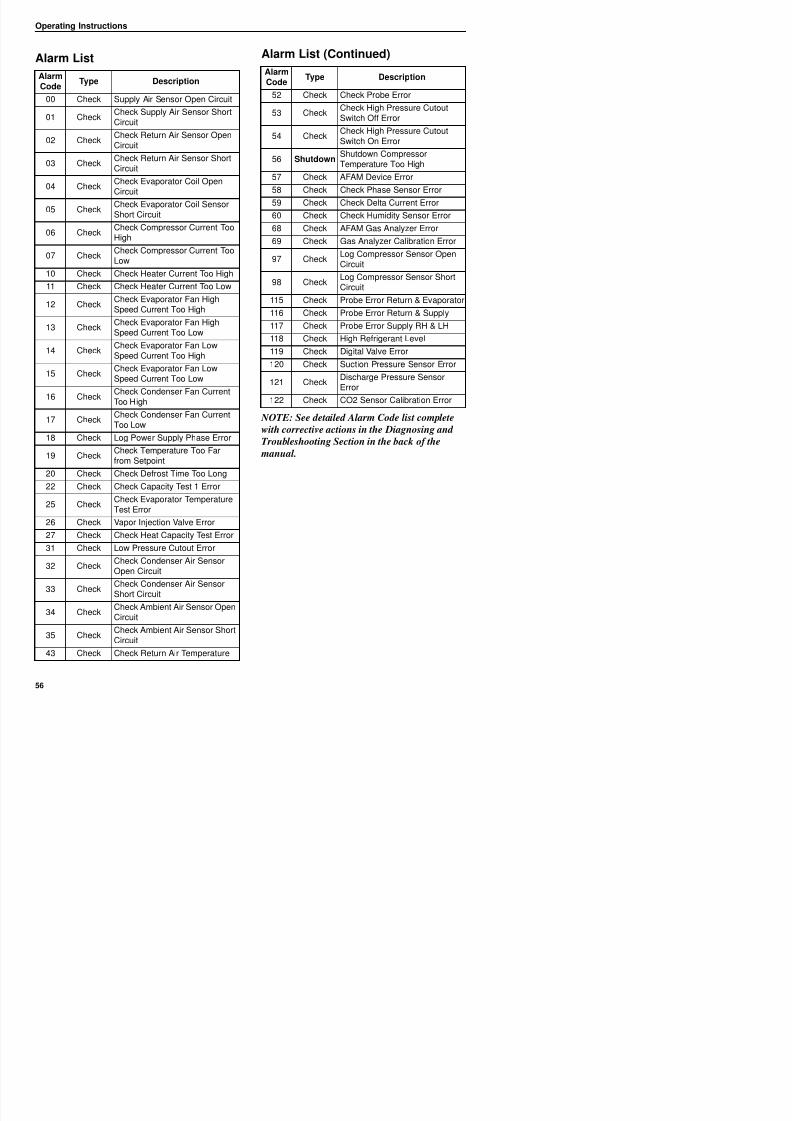
8/12/2019 Termo_King_Magnum_manual.pdf
http://slidepdf.com/reader/full/termokingmagnummanualpdf 56/194
NOTE: See detailed Alarm Code list complete
with corrective actions in the Diagnosing and
Troubleshooting Section in the back of the
manual.
AlarmCode
Type Description
00 Check Supply Air Sensor Open Circuit
01 CheckCheck Supply Air Sensor ShortCircuit
02 CheckCheck Return Air Sensor OpenCircuit
03 CheckCheck Return Air Sensor ShortCircuit
04 Check
Check Evaporator Coil Open
Circuit
05 CheckCheck Evaporator Coil SensorShort Circuit
06 CheckCheck Compressor Current TooHigh
07 CheckCheck Compressor Current TooLow
10 Check Check Heater Current Too High
11 Check Check Heater Current Too Low
12 CheckCheck Evaporator Fan HighSpeed Current Too High
13 CheckCheck Evaporator Fan HighSpeed Current Too Low
14 CheckCheck Evaporator Fan LowSpeed Current Too High
15 Check Check Evaporator Fan LowSpeed Current Too Low
16 CheckCheck Condenser Fan CurrentToo High
17 CheckCheck Condenser Fan CurrentToo Low
18 Check Log Power Supply Phase Error
19 Check
Check Temperature Too Far
from Setpoint
20 Check Check Defrost Time Too Long
22 Check Check Capacity Test 1 Error
25 CheckCheck Evaporator TemperatureTest Error
52 Check Check Probe Error
53 CheckCheck High Pressure CutoutSwitch Off Error
54 CheckCheck High Pressure CutoutSwitch On Error
56 ShutdownShutdown CompressorTemperature Too High
57 Check AFAM Device Error
58 Check Check Phase Sensor Error59 Check Check Delta Current Error
60 Check Check Humidity Sensor Error
68 Check AFAM Gas Analyzer Error
69 Check Gas Analyzer Calibration Error
97 CheckLog Compressor Sensor OpenCircuit
98 Check Log Compressor Sensor ShortCircuit
115 Check Probe Error Return & Evaporator
116 Check Probe Error Return & Supply
117 Check Probe Error Supply RH & LH
118 Check High Refrigerant Level
119 Check Digital Valve Error
120 Check Suction Pressure Sensor Error
121 CheckDischarge Pressure SensorError
122 Check CO2 Sensor Calibration Error
AlarmCode
Type Description
Operating Instructions
Data Menu
Th D t di l l it ti
• Current Phase 1 (Main Power Supply)
• Current Phase 2 (Main Power Supply)
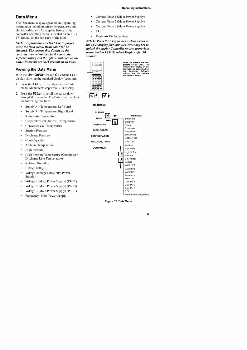
8/12/2019 Termo_King_Magnum_manual.pdf
http://slidepdf.com/reader/full/termokingmagnummanualpdf 57/194
The Data menu displays general unit operating
information including sensor temperatures, unit
electrical data, etc. A complete listing of thecontroller operating menu is located on an 11” x
17” foldout on the last page of the book.
NOTE: Information can ONLY be displayed
using the Data menu. Items can NOT be
changed. The screens that display on the
controller are determined by the controller
software setting and the options installed on theunit. All screens are NOT present on all units.
Viewing the Data Menu
With the UNIT ON/OFF switch ON and the LCD
display showing the standard display (setpoint):
1. Press the F4 key to directly enter the Data
menu. Menu items appear in LCD display.
2. Press the F3 key to scroll the cursor down
through the menu list. The Data menu displays
the following functions:
• Supply Air Temperature, Left Hand
• Supply Air Temperature, Right Hand
• Return Air Temperature
• Evaporator Coil (Defrost) Temperature
• Condenser Coil Temperature
• Suction Pressure
• Discharge Pressure
• Cool Capacity
• Ambient Temperature
• High Pressure
• High Pressure Temperature (Compressor
Discharge Line Temperature)
Current Phase 2 (Main Power Supply)
• Current Phase 3 (Main Power Supply)
• CO2
• Fresh Air Exchange Rate
NOTE: Press the 5 key to lock a Data screen in
the LCD display for 5 minutes. Press any key to
unlock the display.Controller returns to previous
menu level or LCD Standard Display after 30
seconds.
DATA
MAIN MENU
- Supply LH
- Supply RH
- Return
- Evaporator
- Condensor
- Suct. Press
- Disch. Press
- Cool Cap.
- Ambient
- High Press
- High Pr Tmp
- Hum Val.
Bat Voltage
Data Menu
RMM STATE
DATALOGGER
CONFIGURATION
MISC. FUNCTIONS
COMMANDS
ALARMS
NOTE: All screens are NOTpresent on all units. Thescreens that display on thecontroller are determined bythe Controller Softwaresettings and the optionsinstalled on the unit.
Operating Instructions
RMM State Menu
The RMM (Remote Monitoring Modem) State
NOTE: All screens are NOTpresent on all units. The
th t di l th
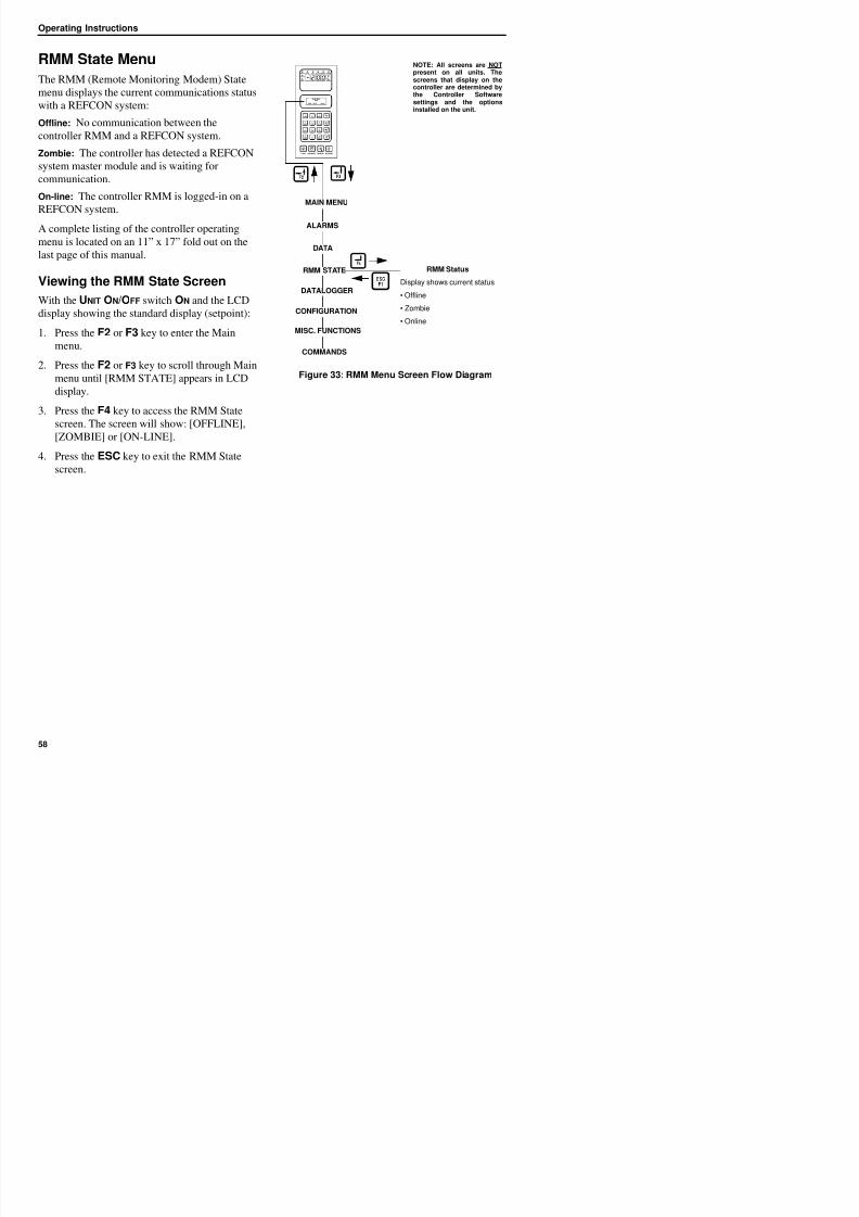
8/12/2019 Termo_King_Magnum_manual.pdf
http://slidepdf.com/reader/full/termokingmagnummanualpdf 58/194
The RMM (Remote Monitoring Modem) State
menu displays the current communications status
with a REFCON system:Offline: No communication between the
controller RMM and a REFCON system.
Zombie: The controller has detected a REFCON
system master module and is waiting for
communication.
On-line: The controller RMM is logged-in on a
REFCON system.
A complete listing of the controller operating
menu is located on an 11” x 17” fold out on the
last page of this manual.
Viewing the RMM State Screen
With the UNIT ON/OFF switch ON and the LCDdisplay showing the standard display (setpoint):
1. Press the F2 or F3 key to enter the Main
menu.
2. Press the F2 or F3 key to scroll through Main
menu until [RMM STATE] appears in LCD
display.
3. Press the F4 key to access the RMM State
screen. The screen will show: [OFFLINE],
[ZOMBIE] or [ON-LINE].
4. Press the ESC key to exit the RMM State
screen.
Figure 33: RMM Menu Screen Flow Diagram
ALARMS
RMM STATE RMM Status
Display shows current status
• Offline
• Zombie
• Online
MAIN MENU
DATA
DATALOGGER
CONFIGURATION
MISC. FUNCTIONS
COMMANDS
screens that display on thecontroller are determined bythe Controller Softwaresettings and the options
installed on the unit.
Operating Instructions
Datalogger Menu
The Datalogger menu contains a list of functions
NOTE: All screens are NOTpresent on all units. Thescreens that display on the
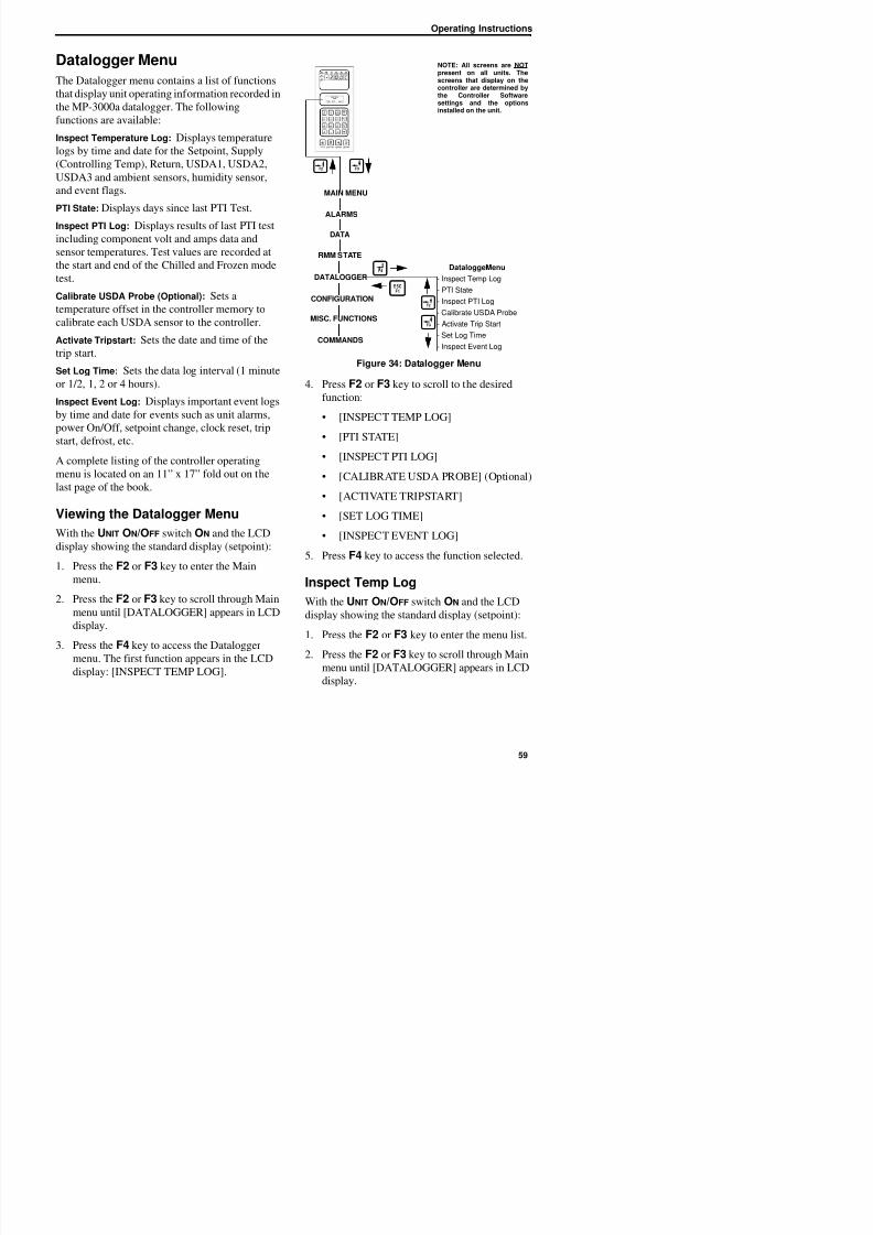
8/12/2019 Termo_King_Magnum_manual.pdf
http://slidepdf.com/reader/full/termokingmagnummanualpdf 59/194
The Datalogger menu contains a list of functions
that display unit operating information recorded in
the MP-3000a datalogger. The followingfunctions are available:
Inspect Temperature Log: Displays temperature
logs by time and date for the Setpoint, Supply
(Controlling Temp), Return, USDA1, USDA2,
USDA3 and ambient sensors, humidity sensor,
and event flags.
PTI State: Displays days since last PTI Test.Inspect PTI Log: Displays results of last PTI test
including component volt and amps data and
sensor temperatures. Test values are recorded at
the start and end of the Chilled and Frozen mode
test.
Calibrate USDA Probe (Optional): Sets a
temperature offset in the controller memory tocalibrate each USDA sensor to the controller.
Activate Tripstart: Sets the date and time of the
trip start.
Set Log Time: Sets the data log interval (1 minute
or 1/2, 1, 2 or 4 hours).
Inspect Event Log: Displays important event logs
by time and date for events such as unit alarms,
power On/Off, setpoint change, clock reset, trip
start, defrost, etc.
A complete listing of the controller operating
menu is located on an 11” x 17” fold out on the
last page of the book.
Viewing the Datalogger Menu
With the UNIT ON/OFF switch ON and the LCD
display showing the standard display (setpoint):
Figure 34: Datalogger Menu
4. Press F2 or F3 key to scroll to the desired
function:
• [INSPECT TEMP LOG]
• [PTI STATE]
• [INSPECT PTI LOG]
• [CALIBRATE USDA PROBE] (Optional)
• [ACTIVATE TRIPSTART]
• [SET LOG TIME]
• [INSPECT EVENT LOG]
5. Press F4 key to access the function selected.
ALARMS
DATA
RMM STATE
DataloggerMenu
- Inspect Temp Log
- PTI State
- Inspect PTI Log
- Calibrate USDA Probe
- Activate Trip Start
- Set Log Time
- Inspect Event Log
MAIN MENU
DATALOGGER
CONFIGURATION
MISC. FUNCTIONS
COMMANDS
screens that display on thecontroller are determined bythe Controller Softwaresettings and the options
installed on the unit.
Operating Instructions
3. Press the F4 key to access the Datalogger
menu. [INSPECT TEMP LOG] appears in the
LCD di l
W = Warning in Last Interval
C = CO2 Active
8/12/2019 Termo_King_Magnum_manual.pdf
http://slidepdf.com/reader/full/termokingmagnummanualpdf 60/194
LCD display.
4. Press the F4 key to enter Temp Log. LCD
display shows the Log Time and the Setpoint,
Supply and Return temperatures of the most
recent log in the first screen.
5. Press the F3 key to scroll through previous
logs of the sensor temperatures currently in
the display. All temperature logs recorded in
the datalogger memory may be viewed on the
LCD display.
6. Press the F4 key again to view additional
sensor log and event flag screens. LCD
display shows USDA1, USDA2, USDA3,
Relative Humidity (rH), Ambient, sensor
readings, and flags etc.
7. Press the F3 key to scroll through previouslogs of the sensor temperatures currently in
the display.
Event Flags for Temperature Log
T = Tripstart Activated
P = Primary Power Off
D = Defrost in Last Interval
O = Temperature Not In-range
h = Humidity Control Active
E = Evaporator High Temperature
H = High Refrigeration Pressure
d = Defrost terminated on time limit
e = Economy mode activated
s = Reefer unit stopped (after PTI)
C CO2 Active
NOTE: All event flags that occurred during a
log interval are displayed.
8. Press the ESC key to exit the Temp Log.
Inspect Event Log
With the UNIT ON/OFF switch ON and the LCD
display showing the standard display (setpoint):
1. Press the F2 or F3 key to enter the Mainmenu.
2. Press the F2 or F3 key to scroll through Main
menu until [DATALOGGER] appears in LCD
display.
3. Press the F4 key to access the Datalogger
menu. [INSPECT TEMP LOG] appears in the
LCD display.
4. Press the F2 or F3 key to scroll through
submenu until [INSPECT EVENT LOG]
appears in LCD display.
5. Press the F4 key to enter PTI log. LCD
display shows the Start Time and PTI test
results of the most recent PTI log.
• To scroll through additional test results in
the log, press the F3 key.
PTI Examples
• PTI stores volt and amps of all power
consuming components
• PTI stores temperatures logged at both the
start and end of Chilled mode and Frozen
mode capacity tests
6 Press the ESC key to exit the Event log
Operating Instructions
each sensor and activate data logging. However,
the USDA Type screen in the Configuration menu
t b t t th t tti d h
NOTE: All screens are NOTpresent on all units. Thescreens that display on the
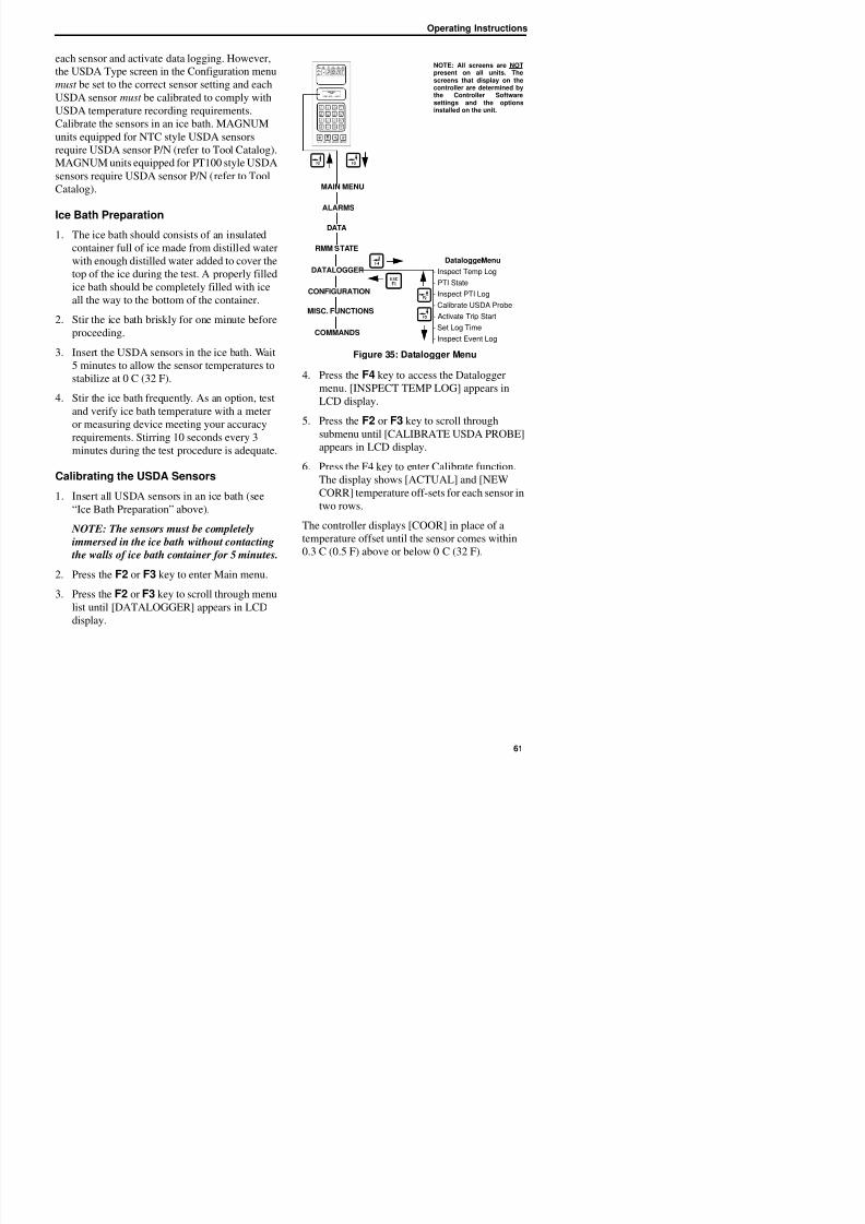
8/12/2019 Termo_King_Magnum_manual.pdf
http://slidepdf.com/reader/full/termokingmagnummanualpdf 61/194
must be set to the correct sensor setting and each
USDA sensor must be calibrated to comply with
USDA temperature recording requirements.Calibrate the sensors in an ice bath. MAGNUM
units equipped for NTC style USDA sensors
require USDA sensor P/N (refer to Tool Catalog).
MAGNUM units equipped for PT100 style USDA
sensors require USDA sensor P/N (refer to Tool
Catalog).
Ice Bath Preparation
1. The ice bath should consists of an insulated
container full of ice made from distilled water
with enough distilled water added to cover the
top of the ice during the test. A properly filled
ice bath should be completely filled with ice
all the way to the bottom of the container.
2. Stir the ice bath briskly for one minute before
proceeding.
3. Insert the USDA sensors in the ice bath. Wait
5 minutes to allow the sensor temperatures to
stabilize at 0 C (32 F).
4. Stir the ice bath frequently. As an option, test
and verify ice bath temperature with a meter
or measuring device meeting your accuracy
requirements. Stirring 10 seconds every 3
minutes during the test procedure is adequate.
Calibrating the USDA Sensors
1. Insert all USDA sensors in an ice bath (see“Ice Bath Preparation” above).
NOTE: The sensors must be completely
immersed in the ice bath without contacting
the walls of ice bath container for 5 minutes
Figure 35: Datalogger Menu
4. Press the F4 key to access the Datalogger
menu. [INSPECT TEMP LOG] appears in
LCD display.5. Press the F2 or F3 key to scroll through
submenu until [CALIBRATE USDA PROBE]
appears in LCD display.
6. Press the F4 key to enter Calibrate function.
The display shows [ACTUAL] and [NEW
CORR] temperature off-sets for each sensor in
two rows.
The controller displays [COOR] in place of a
temperature offset until the sensor comes within
0.3 C (0.5 F) above or below 0 C (32 F).
ALARMS
DATA
RMM STATE
DataloggerMenu
- Inspect Temp Log
- PTI State
- Inspect PTI Log
- Calibrate USDA Probe- Activate Trip Start
- Set Log Time
- Inspect Event Log
MAIN MENU
DATALOGGER
CONFIGURATION
MISC. FUNCTIONS
COMMANDS
p ycontroller are determined bythe Controller Softwaresettings and the options
installed on the unit.
Operating Instructions
The controller displays the actual temperature
offset when the sensor temperature is within 0.3 C
(0 5 F) above or below 0 C (32 F)
Set Trip Start
With the UNIT ON/OFF switch ON and the LCD
8/12/2019 Termo_King_Magnum_manual.pdf
http://slidepdf.com/reader/full/termokingmagnummanualpdf 62/194
(0.5 F) above or below 0 C (32 F).
NOTE: The sensors should be in the ice bath
a total of 15 minutes or more to assure the
sensor temperature has bottomed out.
7. Press the F3 key to release the current actual
temperature offsets from the controller
memory. Observe the sensor temperatures in
the [NEW CORR] row.
8. Press the F4 key to accept the newtemperature offsets when all sensor offsets
read between + 0.3 C (+0.5 F) and - 0.3 C
(-0.5) and have been stable for 5 minutes. The
controller display will show the new offsets in
the [ACTUAL] row.
9. Press the ESC key to exit the Calibrate menu.
display showing the standard display (setpoint):
1. Press the F2 or F3 key to enter the Mainmenu.
2. Press the F2 or F3 key to scroll through menu
list until [DATALOGGER] appears in LCD
display.
3. Press the F4 key to access the Datalogger
menu. [INSPECT TEMP LOG] appears in the
LCD display.
4. Press the F2 or F3 key to scroll through
submenu until [ACTIVATE TRIPSTART]
appears in LCD display.
5. Press the F4 key to enter Tripstart function.
The date and time of the last trip start appears
in the screen.
6. Press the F4 key again to enter a new start of
trip date and time in the log.
NOTE: When a PTI test is completed, the
controller automatically enters a Tripstart in
the log.
7. Press the ESC key to exit the Dataloggermenu.
Operating Instructions
Set Log Time
With the UNIT ON/OFF switch ON and the LCDNOTE: All screens are NOTpresent on all units. Thescreens that display on the
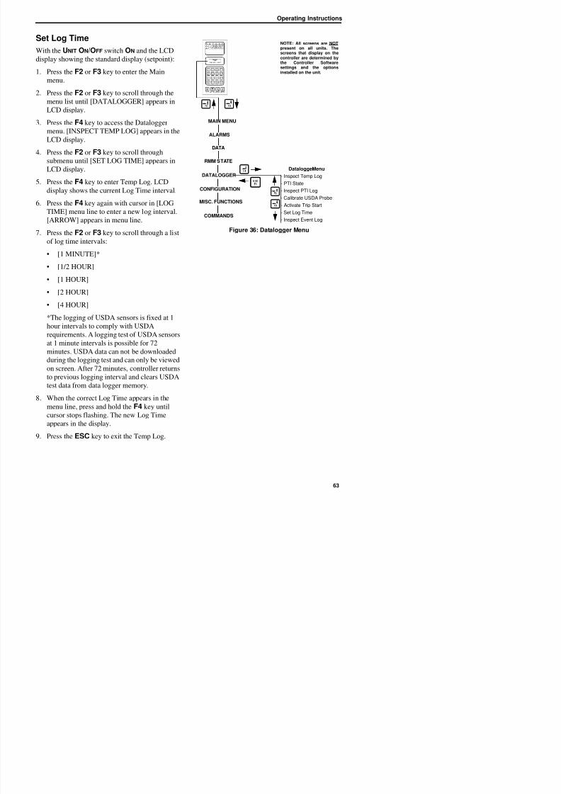
8/12/2019 Termo_King_Magnum_manual.pdf
http://slidepdf.com/reader/full/termokingmagnummanualpdf 63/194
display showing the standard display (setpoint):
1. Press the F2 or F3 key to enter the Mainmenu.
2. Press the F2 or F3 key to scroll through the
menu list until [DATALOGGER] appears in
LCD display.
3. Press the F4 key to access the Datalogger
menu. [INSPECT TEMP LOG] appears in the
LCD display.
4. Press the F2 or F3 key to scroll through
submenu until [SET LOG TIME] appears in
LCD display.
5. Press the F4 key to enter Temp Log. LCD
display shows the current Log Time interval.
6. Press the F4 key again with cursor in [LOG
TIME] menu line to enter a new log interval.
[ARROW] appears in menu line.
7. Press the F2 or F3 key to scroll through a list
of log time intervals:
• [1 MINUTE]*
• [1/2 HOUR]
• [1 HOUR]
• [2 HOUR]
• [4 HOUR]
*The logging of USDA sensors is fixed at 1
hour intervals to comply with USDArequirements. A logging test of USDA sensors
at 1 minute intervals is possible for 72
minutes. USDA data can not be downloaded
during the logging test and can only be viewed
Figure 36: Datalogger Menu
ALARMS
DATA
RMM STATE
DataloggerMenu
- Inspect Temp Log
- PTI State
- Inspect PTI Log
- Calibrate USDA Probe- Activate Trip Start
- Set Log Time
- Inspect Event Log
MAIN MENU
DATALOGGER
CONFIGURATION
MISC. FUNCTIONS
COMMANDS
controller are determined bythe Controller Softwaresettings and the options
installed on the unit.
Operating Instructions
Inspect Event Log
With the UNIT ON/OFF switch ON and the LCD
di l h i h d d di l i
Event Examples
• Controller alarm status (alarms set/cleared)
8/12/2019 Termo_King_Magnum_manual.pdf
http://slidepdf.com/reader/full/termokingmagnummanualpdf 64/194
display showing the standard display (setpoint):
1. Press the F2 or F3 key to enter Main menu.
2. Press the F2 or F3 key to scroll through Main
menu until [DATALOGGER] appears in LCD
display.
3. Press the F4 key to access the Datalogger
menu. [INSPECT TEMP LOG] appears in the
LCD display.
4. Press the F2 or F3 key to scroll through
submenu until [INSPECT EVENT LOG]
appears in LCD display.
5. Press the F4 key to enter Event Log. LCD
display shows the Log Time and the most
recent event.
• To scroll through previous event log
screens, press the F3 key. All event logs
recorded in the datalogger memory may be
viewed on the LCD display.
• Main power On/Off status (humidity On/Off,
temperature setpoint, and main power Hz)
• 12 Vdc battery discharge test (battery voltage,
total unit and compressor hours if main power
on) — this event logged at once a day
• Change temperature setpoint (new/old
setpoint)
• Change RH setpoint (new/old RH setpoint)
• Change RH status (On/Off)
• Event log retrieval
• Temperature log retrieval
• Trip start
• New container ID
• PTI start (Unit configuration)
• PTI part 1 end (Temperature differences for
tests 1, 2, 3 and heat test
• PTI end
• Defrost start (logged with demand or manual
defrost only)
• Defrost end (start time)
6. Press the ESC key to exit the Event Log.
Operating Instructions
Configuration Menu
The Configuration menu displays a list of
NOTE: All screens are NOTpresent on all units. Thescreens that display on thecontroller are determined by
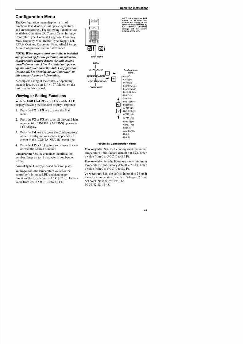
8/12/2019 Termo_King_Magnum_manual.pdf
http://slidepdf.com/reader/full/termokingmagnummanualpdf 65/194
functions that identifies unit operating features
and current settings. The following functions are
available: Container ID, Control Type, In-range,
Controller Type, Contrast, Language, Economy
Max, Economy Min., Reefer Type, Supply LH,
AFAM Options, Evaporator Fans, AFAM Setup,
Auto Configuration and Serial Number.
NOTE: When a spare parts controller is installed
and powered up for the first time, an automatic
configuration feature detects the unit options
installed on a unit. After the initial unit power
up, the controller turns the Auto Configuration
feature off. See “Replacing the Controller” in
this chapter for more information.
A complete listing of the controller operating
menu is located on an 11” x 17” fold out on the
last page in this manual.
Viewing or Setting Functions
With the UNIT ON/OFF switch ON and the LCD
display showing the standard display (setpoint):
1. Press the F2 or F3 key to enter the Main
menu.
2. Press the F2 or F3 key to scroll through Main
menu until [CONFIGURATIONS] appears in
LCD display.
3. Press the F4 key to access the Configurations
screen. Configurations screen appears with
cursor in the [CONTAINER-ID] menu line.4. Press the F2 or F3 key to scroll cursor to view
or reset the desired function:
Container ID: Sets the container identification
Figure 37: Configuration Menu
Economy Max: Sets the Economy mode maximum
temperature limit (factory default = 0.2 C). Enter
l f 0 t 5 0 C (0 t 8 9 F)
DATA
CONFIGURATION
Configuration
Menu
- Cont ID
- Ctrl Type
- In Range
- Economy Max- Economy Min
- 24 Hr. Defrost
- Unit Type
- Zero Curr.
- PRS. Sensor
- Supply LH
- AFAM Opt.
- Gas Analyzer
- AFAM Units
- AFAM Type
- Evap. Type
- Cond. Type
- Chart R.
- Auto Config.
- Unit #
- Unit ID
MAIN MENU
DATALOGGER
MISC. FUNCTIONS
COMMANDS
controller are determined bythe Controller Softwaresettings and the options
installed on the unit.
Operating Instructions
Unit Type: View display value (factory default =
NO HUM). Controller automatically activates
when a humidity sensor is installed for more than
Unit #: Is the TK serial number of the unit itself.
This is a ten digit alpha / numeric entry found
under the UNIT Serial Number on the Serial Plate
8/12/2019 Termo_King_Magnum_manual.pdf
http://slidepdf.com/reader/full/termokingmagnummanualpdf 66/194
1 minute. Setting this value is not necessary.
Pressure Sensor: Sets the pressure sensor toNONE, LOW, HIGH, HIGH+LOW.
Zero Current: Displays zero current On or Off.
Supply LH: View display on or off value (factory
default = off). Controller automatically activates
when a left hand supply sensor is installed for
more than 1 minute. Setting this value is not
necessary.
AFAM Option: Sets the Advanced Fresh Air
Management System to None, AFAM, AFAM+ or
Log.FAE (factory default = None). Controller
automatically activates when an AFAM system
vent door and/or AFAM+ gas sensor is installed
for more than one minute. Setting this value is not
necessary.
Gas Analyzer: Select type of gas sensor.
AFAM Units: Displays whether the fresh air
exchange rate will be displayed in cubic meters
per hour or cubic feet per min.
AFAM Type: Selects the type of AFAM motor.
NONE = No AFAM. FEEDBACK =potentiometer motor. TIMING CUR current
measuring motor. (factory default = TIMING
CUR).
Evaporator Type: Sets the evaporator fan value to
3 fan or 2 fan.
Condenser Type: Sets the condenser fan value to
1/2 HP, 3/4 HP or 2 HP. Must be manually set.Chart R (Electronic Chart Recorder): Must be
manually set to -20 +80 F 31 day, -30 +25 C 31
day, -25 + 25 C 31 day or Not Present.
on the unit.
Unit ID: A 12 digit alpha / numeric containernumber.
NOTE: MAGNUM units without a container
number beginning with MAE, MSF or MWC
must be set for USDA temperature sensing. See
“USDA Type” above.
5. To set a new Configuration screen value:a. Press the F4 key with cursor in the desired
menu line. The Password screen appears.
b. Press the F2 key, A key (password is “A”),
F4 key and then the EXIT key. An Enter
Arrow appears in the hourmeter line.
c. Use the general purpose keypad to enterthe desired value; or press the F3 key to
toggle the value to the desired setting.
d. Press the F4 key and release when the
entry is complete. Press the EXIT key. The
new value appears in the menu line.
6. Repeat steps 4 and 5 to reset additional
configuration values.
7. Press the ESC key to exit the Configurations
screen.
Operating Instructions
Misc. Functions Menu
The Misc. Functions menu displays a list of
f ti th t id tifi t i d d t i h
NOTE: All screens are NOTpresent on all units. Thescreens that display on thecontroller are determined by
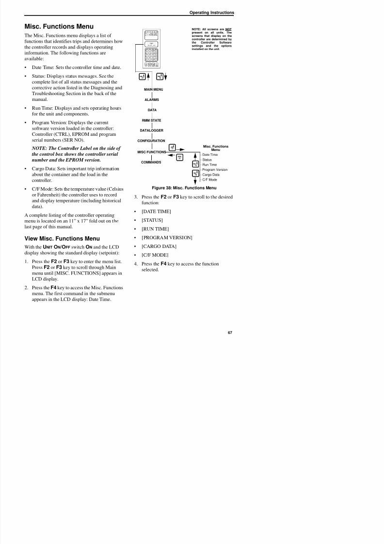
8/12/2019 Termo_King_Magnum_manual.pdf
http://slidepdf.com/reader/full/termokingmagnummanualpdf 67/194
functions that identifies trips and determines how
the controller records and displays operating
information. The following functions are
available:
• Date Time: Sets the controller time and date.
• Status: Displays status messages. See the
complete list of all status messages and the
corrective action listed in the Diagnosing and
Troubleshooting Section in the back of themanual.
• Run Time: Displays and sets operating hours
for the unit and components.
• Program Version: Displays the current
software version loaded in the controller:
Controller (CTRL), EPROM and program
serial numbers (SER NO).
NOTE: The Controller Label on the side of
the control box shows the controller serial
number and the EPROM version.
• Cargo Data: Sets important trip information
about the container and the load in the
controller.
• C/F Mode: Sets the temperature value (Celsius
or Fahrenheit) the controller uses to record
and display temperature (including historical
data).
A complete listing of the controller operating
menu is located on an 11” x 17” fold out on the
last page of this manual.
View Misc. Functions Menu
With the UNIT ON/OFF switch ON and the LCD
Figure 38: Misc. Functions Menu
3. Press the F2 or F3 key to scroll to the desired
function:
• [DATE TIME]
• [STATUS]
• [RUN TIME]
• [PROGRAM VERSION]
• [CARGO DATA]
ALARMS
DATA
RMM STATE
CONFIGURATION
MISC FUNCTIONS
Misc. FunctionsMenu
- Date Time
- Status
- Run Time
- Program Version
- Cargo Data
- C/F Mode
MAIN MENU
DATALOGGER
COMMANDS
ythe Controller Softwaresettings and the options
installed on the unit.
Operating Instructions
Set Date and Time
1. Press the F2 or F3 key to enter the menu list.
Press the F2 or F3 key to scroll to [MISC
View or Set Run Time
1. Press the F2 or F3 key to enter the menu list.
Press the F2 or F3 key to scroll to “MISC
8/12/2019 Termo_King_Magnum_manual.pdf
http://slidepdf.com/reader/full/termokingmagnummanualpdf 68/194
Press the F2 or F3 key to scroll to [MISC.
FUNCTIONS].
2. Press the F4 key to access the Misc. Functions
menu. [DATE TIME] appears in the LCD
display.
3. Press the F4 key to access the Date Time
screen. Date Time screen appears with cursor
in the Time menu line. Display shows time in
“HH.MM.SS” where H = hour, M = minuteand S = second.
4. Press the F4 key with cursor in [TIME] menu
line to enter a new time. An Enter Arrow
appears in the menu line and the previous time
disappears.
5. Enter new time in [HH.MM.SS] format.
Decimal points must be included in the entry
between the hour, minute and second.
NOTE: To scroll backward in the [TIME] or
[DATE] menu line, press and hold the F4
key, then press the F3 key. Press the F1 key
to return keyboard to “numerical” entry
before typing again.
6. Press the F4 key. Then press the EXIT key to
enter time in controller memory. Cursor stops
blinking and new time appears in display.
7. Press the F3 key to move cursor to Date menu
line to enter a new date. Display shows date in
and date in “YY.MM.DD” where Y = year, M
= month and D = day.
8. Press the F4 key with cursor in “DATE” menu
line. An Enter Arrow appears in the menu line
and the previous date disappears.
Press the F2 or F3 key to scroll to MISC.
FUNCTIONS”.
2. Press the F4 key to access the Misc. Functions
menu. “Date Time” appears in the LCD
display. Press the F2 or F3 key to scroll to
“RUN TIME”.
3. Press the F4 key to access the Run Time
screen. The Run Time screen appears with
cursor in “HEAT” menu line.
4. Press the F2 or F3 key to scroll cursor up or
down through cargo data list:
• [HEAT]
• [COMPRESSOR]
• [EVAPORATOR HIGH]
• [EVAPORATOR LOW]
• [CONDENSER]
• [TOTAL]
5. To reset an hourmeter or set hours on a
replacement controller:
a. Press the F4 key with cursor in the desired
menu line. The Password screen appears.
b. Press the F2 key, A key (password is “A”),
F4 key and then the EXIT key. An Enter
Arrow appears in the hourmeter line.
c. Enter the desired run time setting (up to 5
characters).
d. Press and hold the F4 key until the cursor
stops flashing. The new run time appears
in the menu line.
Operating Instructions
Set Cargo Data
1. Press the F2 or F3 key to enter the menu list.
Press the F2 or F3 key to scroll to [MISC.
• When the F1, F2, F3 or F4 key is pressed
to enter a character in the display, the
keypad remains on that “character level”
il h “l l” i l d b
8/12/2019 Termo_King_Magnum_manual.pdf
http://slidepdf.com/reader/full/termokingmagnummanualpdf 69/194
Press the F2 or F3 key to scroll to [MISC.
FUNCTIONS].
2. Press the F4 key to access the Misc. Functions
menu. [DATE TIME] appears in the LCD
display. Press the F2 or F3 key to scroll to
[CARGO DATA].
3. Press the F4 key to access the Cargo Data
screen. Cargo Data screen appears with cursor
in [LOC. BRT] menu line.
4. Press the F2 or F3 key to scroll cursor up or
down through cargo data list:
• [LOC. BRT]
• [CONTENTS]
• [DATE] (Loading Date)
• [VOYAGE]
• [SHIP]
• [LD PORT] (Loading Port)
• [DIS PORT] (Discharge Port)
• [COMMENTS]
5. To enter text in a cargo data line, press the F4
key with cursor in the desired menu line. An
Enter Arrow appears and the cursor flashes in
the selected line. Enter (type) the desired text.
When entering information:
• Enter up to 10 characters of text/numbers
for each menu item.
• Press and hold the F4 key to scroll
backwards in the text box, then the press
the F3 key.
until another “level” is selected by
pressing the F1, F2, F3 or F4 key.6. When the desired text entry is complete, press
the F4 key. Then press the EXIT key. The
cursor stops flashing and the new text appears
in the menu line.
7. Repeat step 5 until all information has been
entered in the Cargo Data screen.
8. Press ESC key to exit the Cargo Data screen.
Change the Temperature DisplayValue (C/F)
1. Press the F2 or F3 key to enter the menu list.
Press the F2 or F3 key to scroll to [MISC.
FUNCTIONS].
2. Press the F4 key to access the Misc. Functions
menu. [DATE TIME] appears in the LCD
display. Press the F2 or F3 key to scroll to
[C/F MODE].
3. Press the F4 key to access the C/F Mode
screen. C/F Mode screen appears with cursor
in the [TEMPERATURE VALUE] menu line.
Display shows [C/F MODE C] where
C = Celsius and F = Fahrenheit.
4. Press the F4 key to change the temperature
value. Cursor moves to end of menu line and
flashes.
5. Press the F2 or F3 key to toggle temperaturevalue in the menu line between [C] and [F].
6. With the desired temperature value in the
menu line, press and hold the F4 key until
Operating Instructions
Operating Instructions
Commands Menu
The Commands menu displays a list of tasks that
b i d Th f ll i d
NOTE: All screens are NOTpresent on all units. Thescreens that display on thecontroller are determined by
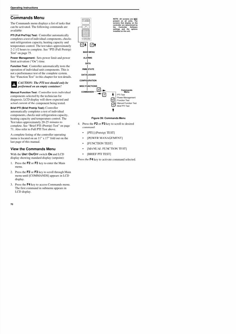
8/12/2019 Termo_King_Magnum_manual.pdf
http://slidepdf.com/reader/full/termokingmagnummanualpdf 70/194
can be activated. The following commands are
available:PTI (Full PreTrip) Test: Controller automatically
completes a test of individual components, checks
unit refrigeration capacity, heating capacity and
temperature control. The test takes approximately
2-2 1/2 hours to complete. See “PTI (Full Pretrip)
Test” on page 75.
Power Management: Sets power limit and powerlimit activation (“On”) time.
Function Test: Controller automatically tests the
operation of individual unit components. This is
not a performance test of the complete system.
See “Function Test” in this chapter for test details.
Manual Function Test: Controller tests individual
components selected by the technician for
diagnosis. LCD display will show expected and
actual current of the component being tested.
Brief PTI (Brief Pretrip Test): Controller
automatically completes a test of individualcomponents, checks unit refrigeration capacity,
heating capacity and temperature control. The
Test takes approximately 20-25 minutes to
complete. See “Brief PTI (Pretrip) Test” on page
71. Also refer to Full PTI Test above.
A complete listing of the controller operating
menu is located on an 11” x 17” fold out on thelast page of this manual.
View the Commands Menu
Figure 39: Commands Menu
4. Press the F2 or F3 key to scroll to desired
command:
• [PTI] [(Pretrip) TEST]
• [POWER MANAGEMENT]
• [FUNCTION TEST]
• [MANUAL FUNCTION TEST]
CAUTION: The PTI test should only be performed on an empty container!
CommandsMenu
- PTI Test
- Power Management
- Function Test
- Manual Function Test
- Brief PTI Test
ALARMS
DATA
RMM STATE
CONFIGURATION
MISC FUNCTIONS
COMMANDS
MAIN MENU
DATALOGGER
ythe Controller Softwaresettings and the options
installed on the unit.
Operating Instructions
Brief PTI (Pretrip) Test
CAUTION: The Brief PTI test should
only be performed on an empty container!
NOTE: All screens are NOTpresent on all units. Thescreens that display on thecontroller are determined bythe Controller Software
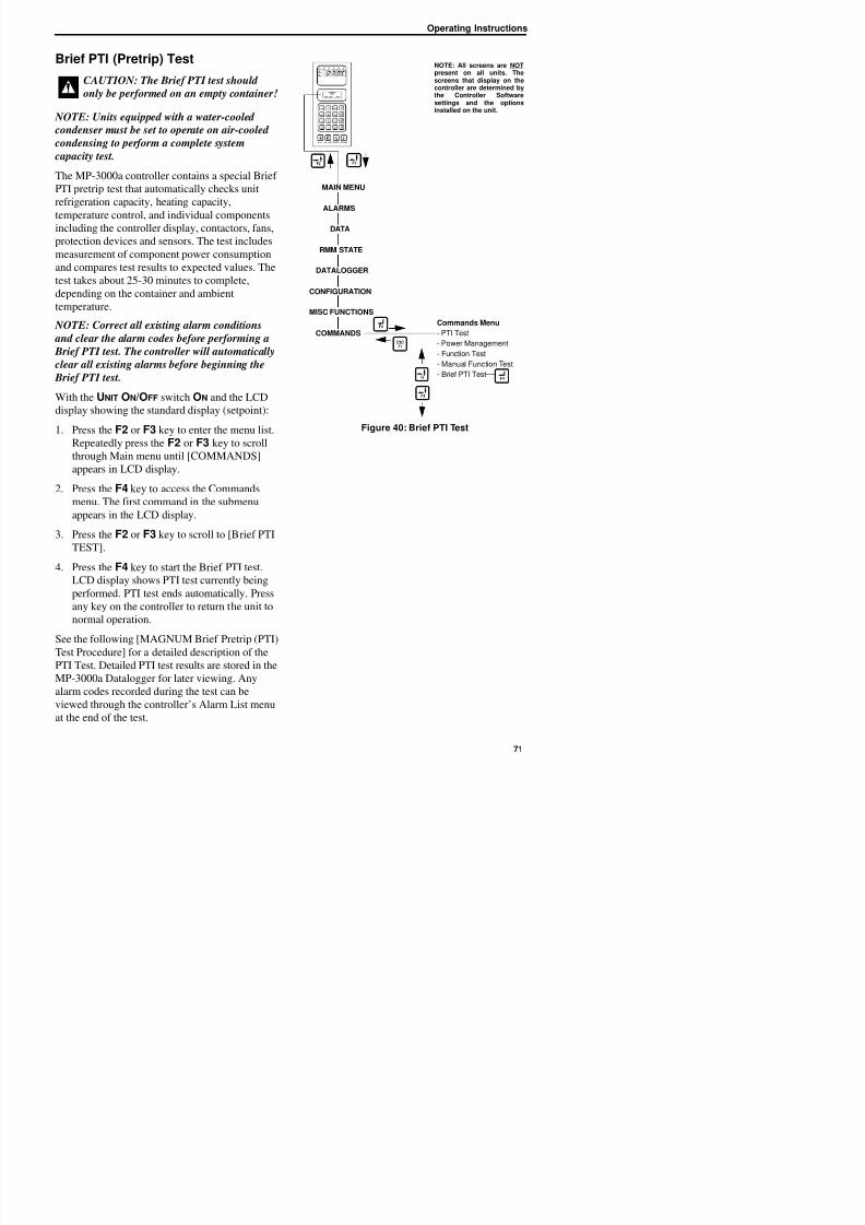
8/12/2019 Termo_King_Magnum_manual.pdf
http://slidepdf.com/reader/full/termokingmagnummanualpdf 71/194
NOTE: Units equipped with a water-cooled condenser must be set to operate on air-cooled
condensing to perform a complete system
capacity test.
The MP-3000a controller contains a special Brief
PTI pretrip test that automatically checks unit
refrigeration capacity, heating capacity,
temperature control, and individual componentsincluding the controller display, contactors, fans,
protection devices and sensors. The test includes
measurement of component power consumption
and compares test results to expected values. The
test takes about 25-30 minutes to complete,
depending on the container and ambient
temperature. NOTE: Correct all existing alarm conditions
and clear the alarm codes before performing a
Brief PTI test. The controller will automatically
clear all existing alarms before beginning the
Brief PTI test.
With the UNIT ON/OFF switch ON and the LCD
display showing the standard display (setpoint):
1. Press the F2 or F3 key to enter the menu list.
Repeatedly press the F2 or F3 key to scroll
through Main menu until [COMMANDS]
appears in LCD display.
2. Press the F4 key to access the Commands
menu. The first command in the submenuappears in the LCD display.
3. Press the F2 or F3 key to scroll to [Brief PTI
TEST].
Figure 40: Brief PTI Test
only be performed on an empty container!
Commands Menu
- PTI Test
- Power Management
- Function Test
- Manual Function Test
- Brief PTI Test
ALARMS
DATA
RMM STATE
CONFIGURATION
MISC FUNCTIONS
COMMANDS
MAIN MENU
DATALOGGER
the Controller Softwaresettings and the optionsinstalled on the unit.
Operating Instructions
MAGNUM Brief PTI Test
LCD Display* Description PossibleAlarms
Duration
(Time)
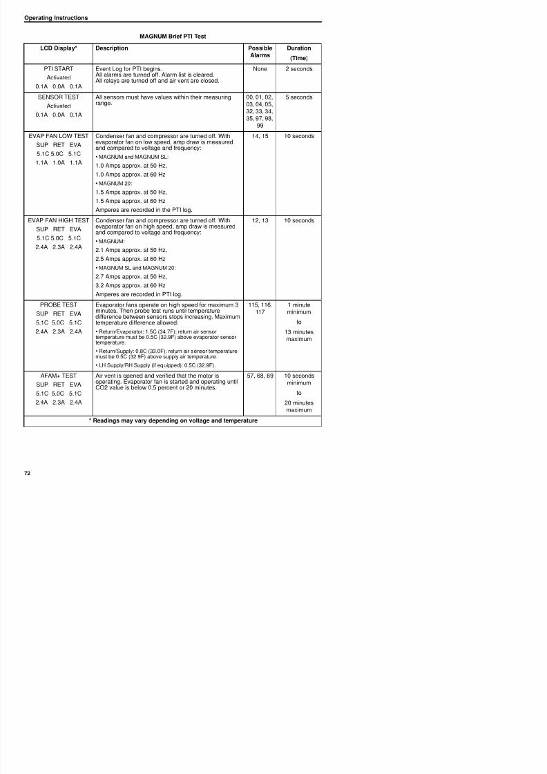
8/12/2019 Termo_King_Magnum_manual.pdf
http://slidepdf.com/reader/full/termokingmagnummanualpdf 72/194
PTI START
Activated
0.1A 0.0A 0.1A
Event Log for PTI begins.All alarms are turned off. Alarm list is cleared.All relays are turned off and air vent are closed.
None 2 seconds
SENSOR TEST
Activated
0.1A 0.0A 0.1A
All sensors must have values within their measuringrange.
00, 01, 02,03, 04, 05,32, 33, 34,35, 97, 98,
99
5 seconds
EVAP FAN LOW TEST
SUP RET EVA
5.1C 5.0C 5.1C
1.1A 1.0A 1.1A
Condenser fan and compressor are turned off. Withevaporator fan on low speed, amp draw is measuredand compared to voltage and frequency:
• MAGNUM and MAGNUM SL:
1.0 Amps approx. at 50 Hz,
1.0 Amps approx. at 60 Hz
• MAGNUM 20:
1.5 Amps approx. at 50 Hz,
1.5 Amps approx. at 60 Hz
Amperes are recorded in the PTI log.
14, 15 10 seconds
EVAP FAN HIGH TEST
SUP RET EVA
5.1C 5.0C 5.1C
2.4A 2.3A 2.4A
Condenser fan and compressor are turned off. Withevaporator fan on high speed, amp draw is measuredand compared to voltage and frequency:
• MAGNUM:
2.1 Amps approx. at 50 Hz,
2.5 Amps approx. at 60 Hz
• MAGNUM SL and MAGNUM 20:
2.7 Amps approx. at 50 Hz,
3.2 Amps approx. at 60 Hz
Amperes are recorded in PTI log.
12, 13 10 seconds
PROBE TEST
SUP RET EVA
5.1C 5.0C 5.1C
2.4A 2.3A 2.4A
Evaporator fans operate on high speed for maximum 3minutes. Then probe test runs until temperature
difference between sensors stops increasing. Maximumtemperature difference allowed:
• Return/Evaporator: 1.5C (34.7F); return air sensortemperature must be 0.5C (32.9F) above evaporator sensortemperature.
• Return/Supply: 0 8C (33 0F); return air sensor temperature
115, 116,117
1 minuteminimum
to
13 minutesmaximum
Operating Instructions
MAGNUM Brief PTI Test
LCD Display* Description PossibleAlarms
Duration
(Time)
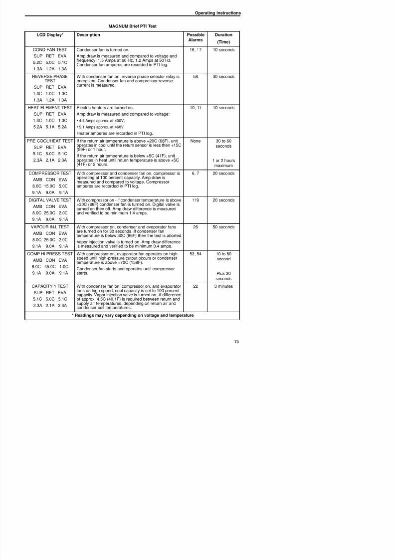
8/12/2019 Termo_King_Magnum_manual.pdf
http://slidepdf.com/reader/full/termokingmagnummanualpdf 73/194
COND FAN TEST
SUP RET EVA
5.2C 5.0C 5.1C
1.3A 1.2A 1.3A
Condenser fan is turned on.
Amp draw is measured and compared to voltage andfrequency: 1.5 Amps at 60 Hz, 1.2 Amps at 50 Hz.Condenser fan amperes are recorded in PTI log.
16, 17 10 seconds
REVERSE PHASETEST
SUP RET EVA
1.3C 1.0C 1.3C
1.3A 1.2A 1.3A
With condenser fan on, reverse phase selector relay isenergized. Condenser fan and compressor reversecurrent is measured.
58 30 seconds
HEAT ELEMENT TEST
SUP RET EVA
1.3C 1.0C 1.3C
5.2A 5.1A 5.2A
Electric heaters are turned on.
Amp draw is measured and compared to voltage:
• 4.4 Amps approx. at 400V;
• 5.1 Amps approx. at 460V.
Heater amperes are recorded in PTI log.
10, 11 10 seconds
PRE COOL/HEAT TESTSUP RET EVA
5.1C 5.0C 5.1C
2.3A 2.1A 2.3A
If the return air temperature is above +20C (68F), unitoperates in cool until the return sensor is less then +15C(59F) or 1 hour.
If the return air temperature is below +5C (41F), unitoperates in heat until return temperature is above +5C(41F) or 2 hours.
None 30 to 60seconds
1 or 2 hoursmaximum
COMPRESSOR TEST
AMB CON EVA
8.0C 15.0C 5.0C9.1A 9.0A 9.1A
With compressor and condenser fan on, compressor isoperating at 100 percent capacity. Amp draw ismeasured and compared to voltage. Compressor
amperes are recorded in PTI log.
6, 7 20 seconds
DIGITAL VALVE TEST
AMB CON EVA
8.0C 25.0C 2.0C
9.1A 9.0A 9.1A
With compressor on - if condenser temperature is above+30C (86F) condenser fan is turned on. Digital valve isturned on then off. Amp draw difference is measuredand verified to be minimum 1.4 amps.
119 20 seconds
VAPOUR INJ. TEST
AMB CON EVA
8.0C 25.0C 2.0C
9.1A 9.0A 9.1A
With compressor on, condenser and evaporator fans
are turned on for 30 seconds. If condenser fantemperature is below 30C (86F) then the test is aborted.
Vapor injection valve is turned on. Amp draw differenceis measured and verified to be minimum 0.4 amps.
26 50 seconds
COMP HI PRESS TEST With compressor on evaporator fan operates on high 53 54 10 to 60
Operating Instructions
MAGNUM Brief PTI Test
LCD Display* Description PossibleAlarms
Duration
(Time)
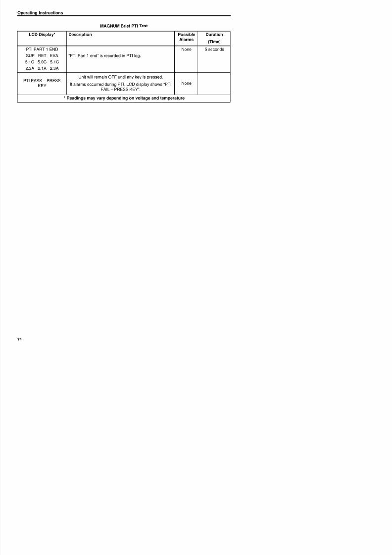
8/12/2019 Termo_King_Magnum_manual.pdf
http://slidepdf.com/reader/full/termokingmagnummanualpdf 74/194
PTI PART 1 END
SUP RET EVA
5.1C 5.0C 5.1C
2.3A 2.1A 2.3A
“PTI Part 1 end” is recorded in PTI log.
None 5 seconds
PTI PASS – PRESSKEY
Unit will remain OFF until any key is pressed.
If alarms occurred during PTI, LCD display shows “PTIFAIL – PRESS KEY”.
None
* Readings may vary depending on voltage and temperature
Operating Instructions
PTI (Full Pretrip) Test
CAUTION: The Full PTI test should only
be performed on an empty container!
NOTE: All screens are NOTpresent on all units. Thescreens that display on thecontroller are determined bythe Controller Softwaresettings and the options
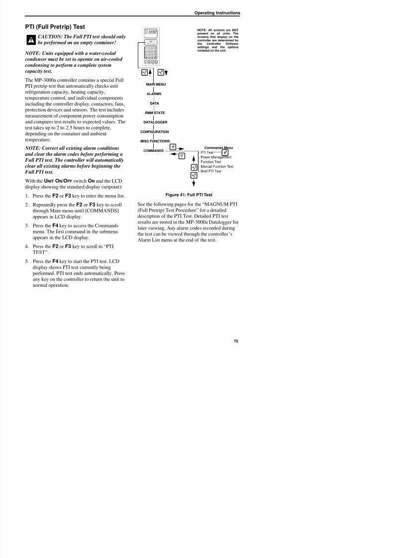
8/12/2019 Termo_King_Magnum_manual.pdf
http://slidepdf.com/reader/full/termokingmagnummanualpdf 75/194
NOTE: Units equipped with a water-cooled condenser must be set to operate on air-cooled
condensing to perform a complete system
capacity test.
The MP-3000a controller contains a special Full
PTI pretrip test that automatically checks unit
refrigeration capacity, heating capacity,
temperature control, and individual componentsincluding the controller display, contactors, fans,
protection devices and sensors. The test includes
measurement of component power consumption
and compares test results to expected values. The
test takes up to 2 to 2.5 hours to complete,
depending on the container and ambient
temperature. NOTE: Correct all existing alarm conditions
and clear the alarm codes before performing a
Full PTI test. The controller will automatically
clear all existing alarms before beginning the
Full PTI test.
With the UNIT ON/OFF switch ON and the LCD
display showing the standard display (setpoint):
1. Press the F2 or F3 key to enter the menu list.
2. Repeatedly press the F2 or F3 key to scroll
through Main menu until [COMMANDS]
appears in LCD display.
3. Press the F4 key to access the Commands
menu. The first command in the submenuappears in the LCD display.
4. Press the F2 or F3 key to scroll to “PTI
TEST”
Figure 41: Full PTI Test
See the following pages for the “MAGNUM PTI
(Full Pretrip) Test Procedure” for a detailed
description of the PTI Test. Detailed PTI test
results are stored in the MP-3000a Datalogger for
later viewing. Any alarm codes recorded duringthe test can be viewed through the controller’s
Alarm List menu at the end of the test.
Commands Menu
- PTI Test
- Power Management
- Function Test
- Manual Function Test
- Brief PTI Test
ALARMS
DATA
RMM STATE
CONFIGURATION
MISC FUNCTIONS
COMMANDS
MAIN MENU
DATALOGGER
settings and the optionsinstalled on the unit.
Operating Instructions
MAGNUM PTI Full Pretrip Test
LCD Display* Description Possible Duration
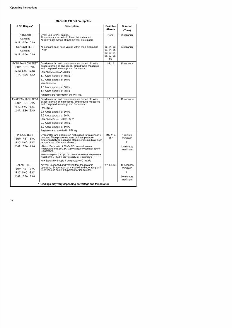
8/12/2019 Termo_King_Magnum_manual.pdf
http://slidepdf.com/reader/full/termokingmagnummanualpdf 76/194
Alarms(Time)
PTI START
Activated
0.1A 0.0A 0.1A
Event Log for PTI begins.All alarms are turned off. Alarm list is cleared.All relays are turned off and air vent are closed.
None 2 seconds
SENSOR TEST
Activated
0.1A 0.0A 0.1A
All sensors must have values within their measuringrange.
00, 01, 02,03, 04, 05,32, 33, 34,
35, 97, 98,99
5 seconds
EVAP FAN LOW TEST
SUP RET EVA
5.1C 5.0C 5.1C
1.1A 1.0A 1.1A
Condenser fan and compressor are turned off. Withevaporator fan on low speed, amp draw is measuredand compared to voltage and frequency:
• MAGNUM and MAGNUM SL:
1.0 Amps approx. at 50 Hz,
1.0 Amps approx. at 60 Hz
• MAGNUM 20:
1.5 Amps approx. at 50 Hz,
1.5 Amps approx. at 60 Hz
Amperes are recorded in the PTI log.
14, 15 10 seconds
EVAP FAN HIGH TEST
SUP RET EVA
5.1C 5.0C 5.1C
2.4A 2.3A 2.4A
Condenser fan and compressor are turned off. Withevaporator fan on high speed, amp draw is measuredand compared to voltage and frequency:
• MAGNUM:
2.1 Amps approx. at 50 Hz,
2.5 Amps approx. at 60 Hz
• MAGNUM SL and MAGNUM 20:
2.7 Amps approx. at 50 Hz,
3.2 Amps approx. at 60 Hz
Amperes are recorded in PTI log.
12, 13 10 seconds
PROBE TESTSUP RET EVA
5.1C 5.0C 5.1C
2.4A 2.3A 2.4A
Evaporator fans operate on high speed for maximum 3minutes. Then probe test runs until temperaturedifference between sensors stops increasing. Maximumtemperature difference allowed:
• Return/Evaporator: 1.5C (34.7F); return air sensortemperature must be 0 5C (32 9F) above evaporator sensor
115, 116,117
1 minuteminimum
to
13 minutesi
Operating Instructions
COND FAN TEST C d f i d d
MAGNUM PTI Full Pretrip Test
LCD Display* Description PossibleAlarms
Duration
(Time)
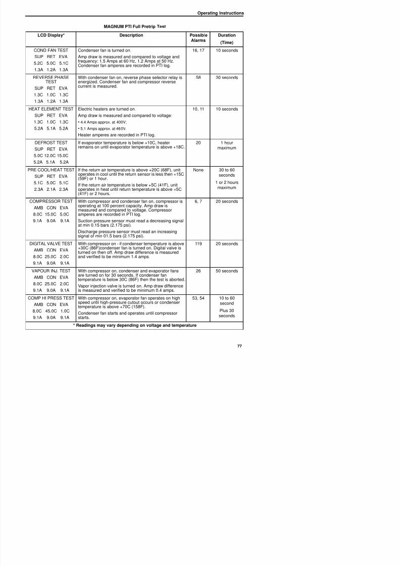
8/12/2019 Termo_King_Magnum_manual.pdf
http://slidepdf.com/reader/full/termokingmagnummanualpdf 77/194
COND FAN TEST
SUP RET EVA
5.2C 5.0C 5.1C
1.3A 1.2A 1.3A
Condenser fan is turned on.
Amp draw is measured and compared to voltage andfrequency: 1.5 Amps at 60 Hz, 1.2 Amps at 50 Hz.Condenser fan amperes are recorded in PTI log.
16, 17 10 seconds
REVERSE PHASETEST
SUP RET EVA
1.3C 1.0C 1.3C
1.3A 1.2A 1.3A
With condenser fan on, reverse phase selector relay isenergized. Condenser fan and compressor reversecurrent is measured.
58 30 seconds
HEAT ELEMENT TEST
SUP RET EVA
1.3C 1.0C 1.3C
5.2A 5.1A 5.2A
Electric heaters are turned on.
Amp draw is measured and compared to voltage:
• 4.4 Amps approx. at 400V;
• 5.1 Amps approx. at 460V.
Heater amperes are recorded in PTI log.
10, 11 10 seconds
DEFROST TESTSUP RET EVA
5.0C 12.0C 15.0C
5.2A 5.1A 5.2A
If evaporator temperature is below +10C, heaterremains on until evaporator temperature is above +18C. 20 1 hourmaximum
PRE COOL/HEAT TEST
SUP RET EVA
5.1C 5.0C 5.1C
2.3A 2.1A 2.3A
If the return air temperature is above +20C (68F), unitoperates in cool until the return sensor is less then +15C(59F) or 1 hour.
If the return air temperature is below +5C (41F), unit
operates in heat until return temperature is above +5C(41F) or 2 hours.
None 30 to 60seconds
1 or 2 hours
maximum
COMPRESSOR TEST
AMB CON EVA
8.0C 15.0C 5.0C
9.1A 9.0A 9.1A
With compressor and condenser fan on, compressor isoperating at 100 percent capacity. Amp draw ismeasured and compared to voltage. Compressoramperes are recorded in PTI log.
Suction pressure sensor must read a decreasing signalat min 0.15 bars (2.175 psi).
Discharge pressure sensor must read an increasingsignal of min 01.5 bars (2.175 psi).
6, 7 20 seconds
DIGITAL VALVE TEST
AMB CON EVA
8 0C 25 0C 2 0C
With compressor on - if condenser temperature is above+30C (86F)condenser fan is turned on. Digital valve isturned on then off. Amp draw difference is measuredand verified to be minimum 1 4 amps
119 20 seconds
Operating Instructions
PRE COOL/HEAT TEST If th t i t t i b 20C (68F) it N 30 t 60
MAGNUM PTI Full Pretrip Test
LCD Display* Description PossibleAlarms
Duration
(Time)
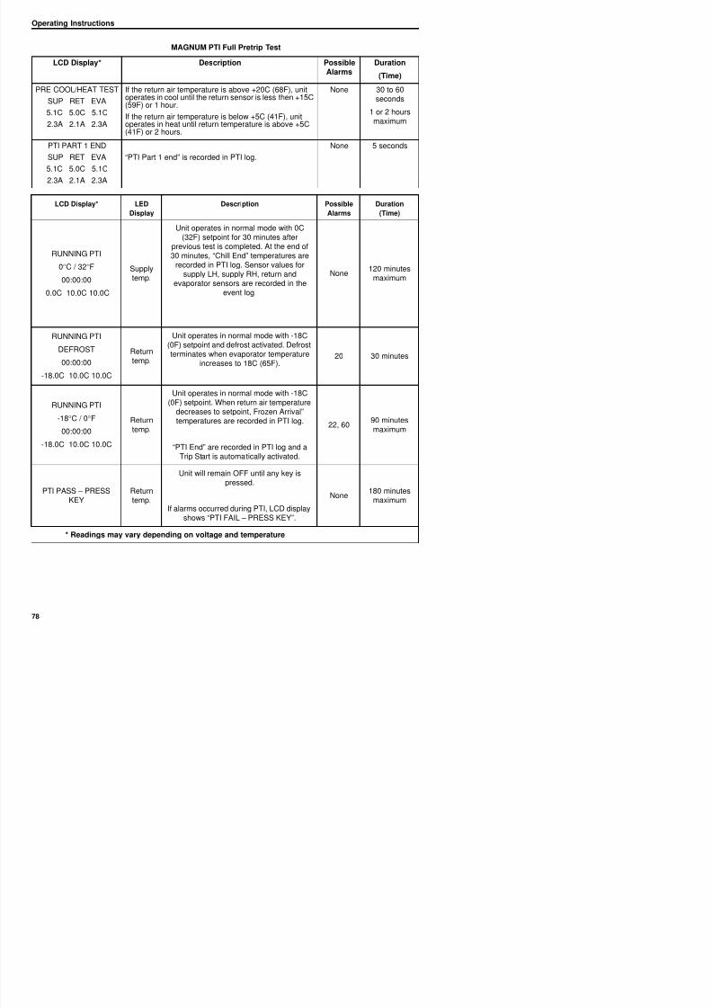
8/12/2019 Termo_King_Magnum_manual.pdf
http://slidepdf.com/reader/full/termokingmagnummanualpdf 78/194
PRE COOL/HEAT TEST
SUP RET EVA
5.1C 5.0C 5.1C
2.3A 2.1A 2.3A
If the return air temperature is above +20C (68F), unitoperates in cool until the return sensor is less then +15C(59F) or 1 hour.
If the return air temperature is below +5C (41F), unitoperates in heat until return temperature is above +5C(41F) or 2 hours.
None 30 to 60seconds
1 or 2 hoursmaximum
PTI PART 1 END
SUP RET EVA
5.1C 5.0C 5.1C
2.3A 2.1A 2.3A
“PTI Part 1 end” is recorded in PTI log.
None 5 seconds
LCD Display* LED
Display
Description Possible
Alarms
Duration
(Time)
RUNNING PTI0°C / 32°F
00:00:00
0.0C 10.0C 10.0C
Supplytemp.
Unit operates in normal mode with 0C(32F) setpoint for 30 minutes after
previous test is completed. At the end of
30 minutes, “Chill End” temperatures arerecorded in PTI log. Sensor values for
supply LH, supply RH, return andevaporator sensors are recorded in the
event log.
None120 minutes
maximum
RUNNING PTI
DEFROST
00:00:00
-18.0C 10.0C 10.0C
Returntemp.
Unit operates in normal mode with -18C(0F) setpoint and defrost activated. Defrostterminates when evaporator temperature
increases to 18C (65F).20 30 minutes
RUNNING PTI
-18°C / 0°F
00:00:00
-18.0C 10.0C 10.0C
Returntemp.
Unit operates in normal mode with -18C(0F) setpoint. When return air temperature
decreases to setpoint, Frozen Arrival”temperatures are recorded in PTI log.
“PTI End” are recorded in PTI log and aTrip Start is automatically activated
22, 6090 minutesmaximum
Operating Instructions
Function Test
The MP-3000a controller contains a special
function test that automatically tests individual
components including the controller display
NOTE: All screens are NOTpresent on all units. Thescreens that display on thecontroller are determined bythe Controller Softwaresettings and the optionsinstalled on the nit
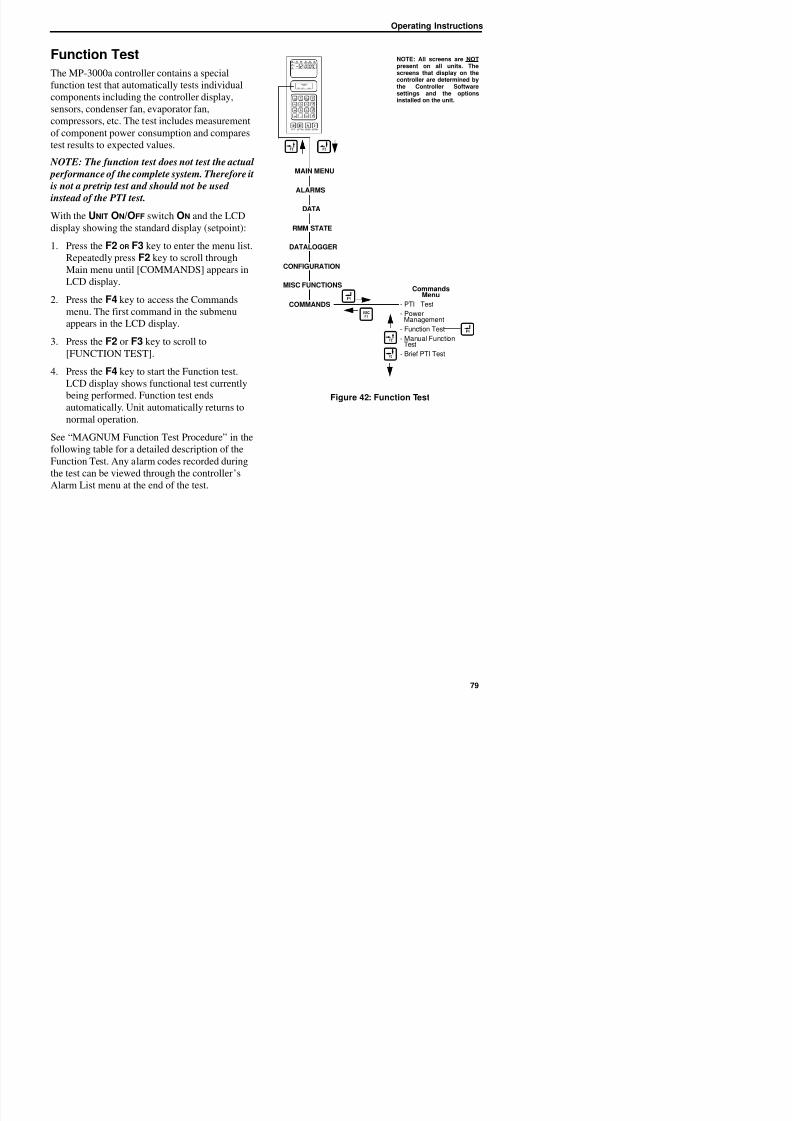
8/12/2019 Termo_King_Magnum_manual.pdf
http://slidepdf.com/reader/full/termokingmagnummanualpdf 79/194
components including the controller display,
sensors, condenser fan, evaporator fan,compressors, etc. The test includes measurement
of component power consumption and compares
test results to expected values.
NOTE: The function test does not test the actual
performance of the complete system. Therefore it
is not a pretrip test and should not be used
instead of the PTI test.
With the UNIT ON/OFF switch ON and the LCD
display showing the standard display (setpoint):
1. Press the F2 OR F3 key to enter the menu list.
Repeatedly press F2 key to scroll through
Main menu until [COMMANDS] appears in
LCD display.2. Press the F4 key to access the Commands
menu. The first command in the submenu
appears in the LCD display.
3. Press the F2 or F3 key to scroll to
[FUNCTION TEST].
4. Press the F4 key to start the Function test.LCD display shows functional test currently
being performed. Function test ends
automatically. Unit automatically returns to
normal operation.
See “MAGNUM Function Test Procedure” in the
following table for a detailed description of the
Function Test. Any alarm codes recorded duringthe test can be viewed through the controller’s
Alarm List menu at the end of the test.
Figure 42: Function Test
CommandsMenu
- PTI Test
- PowerManagement
- Function Test
- Manual FunctionTest
- Brief PTI Test
ALARMS
DATA
RMM STATE
CONFIGURATION
MISC FUNCTIONS
COMMANDS
MAIN MENU
DATALOGGER
installed on the unit.
Operating Instructions
MAGNUM Function Test
LCD Display* Description PossibleAlarms
Duration
(Time)
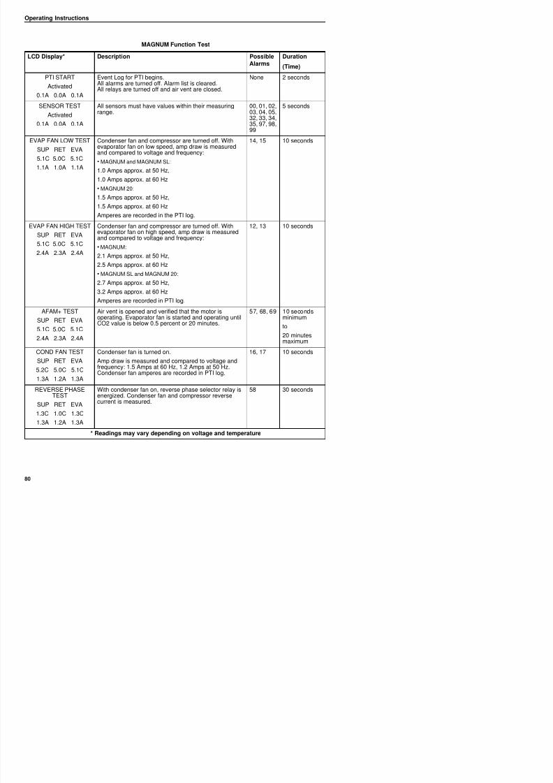
8/12/2019 Termo_King_Magnum_manual.pdf
http://slidepdf.com/reader/full/termokingmagnummanualpdf 80/194
PTI START
Activated
0.1A 0.0A 0.1A
Event Log for PTI begins.All alarms are turned off. Alarm list is cleared.All relays are turned off and air vent are closed.
None 2 seconds
SENSOR TEST
Activated
0.1A 0.0A 0.1A
All sensors must have values within their measuringrange.
00, 01, 02,03, 04, 05,32, 33, 34,35, 97, 98,99
5 seconds
EVAP FAN LOW TEST
SUP RET EVA
5.1C 5.0C 5.1C
1.1A 1.0A 1.1A
Condenser fan and compressor are turned off. Withevaporator fan on low speed, amp draw is measuredand compared to voltage and frequency:
• MAGNUM and MAGNUM SL:
1.0 Amps approx. at 50 Hz,
1.0 Amps approx. at 60 Hz
• MAGNUM 20:
1.5 Amps approx. at 50 Hz,1.5 Amps approx. at 60 Hz
Amperes are recorded in the PTI log.
14, 15 10 seconds
EVAP FAN HIGH TEST
SUP RET EVA
5.1C 5.0C 5.1C
2.4A 2.3A 2.4A
Condenser fan and compressor are turned off. Withevaporator fan on high speed, amp draw is measuredand compared to voltage and frequency:
• MAGNUM:
2.1 Amps approx. at 50 Hz,
2.5 Amps approx. at 60 Hz
• MAGNUM SL and MAGNUM 20:
2.7 Amps approx. at 50 Hz,
3.2 Amps approx. at 60 Hz
Amperes are recorded in PTI log.
12, 13 10 seconds
AFAM+ TEST
SUP RET EVA
5.1C 5.0C 5.1C
2.4A 2.3A 2.4A
Air vent is opened and verified that the motor isoperating. Evaporator fan is started and operating until
CO2 value is below 0.5 percent or 20 minutes.
57, 68, 69 10 secondsminimum
to
20 minutesmaximum
COND FAN TEST Condenser fan is turned on. 16, 17 10 seconds
Operating Instructions
HEAT ELEMENT TEST Electric heaters are turned on 10 11 10 seconds
MAGNUM Function Test
LCD Display* Description PossibleAlarms
Duration
(Time)
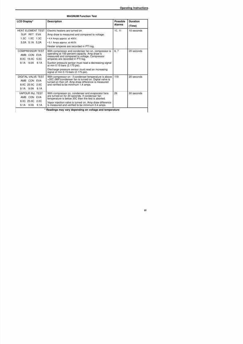
8/12/2019 Termo_King_Magnum_manual.pdf
http://slidepdf.com/reader/full/termokingmagnummanualpdf 81/194
HEAT ELEMENT TEST
SUP RET EVA
1.3C 1.0C 1.3C
5.2A 5.1A 5.2A
Electric heaters are turned on.
Amp draw is measured and compared to voltage:
• 4.4 Amps approx. at 400V;
• 5.1 Amps approx. at 460V.
Heater amperes are recorded in PTI log.
10, 11 10 seconds
COMPRESSOR TEST
AMB CON EVA
8.0C 15.0C 5.0C9.1A 9.0A 9.1A
With compressor and condenser fan on, compressor isoperating at 100 percent capacity. Amp draw ismeasured and compared to voltage. Compressor
amperes are recorded in PTI log.Suction pressure sensor must read a decreasing signalat min 0.15 bars (2.175 psi).
Discharge pressure sensor must read an increasingsignal of min 0.15 bars (2.175 psi).
6, 7 20 seconds
DIGITAL VALVE TEST
AMB CON EVA
8.0C 25.0C 2.0C
9.1A 9.0A 9.1A
With compressor on - if condenser temperature is above+30C (86F)condenser fan is turned on. Digital valve isturned on then off. Amp draw difference is measuredand verified to be minimum 1.4 amps.
119 20 seconds
VAPOUR INJ. TEST
AMB CON EVA
8.0C 25.0C 2.0C
9.1A 9.0A 9.1A
With compressor on, condenser and evaporator fansare turned on for 30 seconds. If condenser fantemperature is below 30C then the test is aborted.
Vapor injection valve is turned on. Amp draw differenceis measured and verified to be minimum 0.4 amps.
26 50 seconds
* Readings may vary depending on voltage and temperature
Operating Instructions
Manual Function Test
The Manual Function Test menu allows
technicians to perform specific diagnostic tests on
individual components or turn several
NOTE: All screens are NOTpresent on all units. Thescreens that display on thecontroller are determined bythe Controller Softwaresettings and the optionsinstalled on the unit.
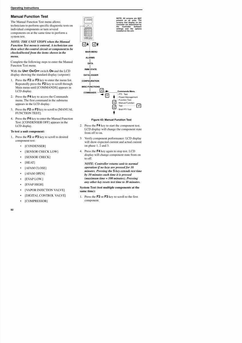
8/12/2019 Termo_King_Magnum_manual.pdf
http://slidepdf.com/reader/full/termokingmagnummanualpdf 82/194
components on at the same time to perform asystem test.
NOTE: THE UNIT STOPS when the Manual
Function Test menu is entered. A technician can
then select the control circuit or component to be
checked/tested from the items shown in the
menu.
Complete the following steps to enter the Manual
Function Test menu.
With the UNIT ON/OFF switch ON and the LCD
display showing the standard display (setpoint):
1. Press the F2 or F3 key to enter the menu list.
Repeatedly press the F2 key to scroll through
Main menu until [COMMANDS] appears inLCD display.
2. Press the F4 key to access the Commands
menu. The first command in the submenu
appears in the LCD display.
3. Press the F2 or F3 key to scroll to [MANUAL
FUNCTION TEST].4. Press the F4 key to enter the Manual Function
Test: [CONDENSER OFF] appears in the
LCD display.
To test a unit component:
1. Press the F2 or F3 key to scroll to desired
component test:• [CONDENSER]
• [SENSOR CHECK LOW]
Figure 43: Manual Function Test
2. Press the F4 key to start the component test.
LCD display will change the component state
from off to on.
3. Verify component performance: LCD display
will show expected current and actual currenton phase 1, 2 and 3.
4. Press the F4 key again to stop test. LCD
display will change component state from on
Commands Menu
- PTI Test
- Power Management
- Function Test
- Manual Function
Test
- Brief PTI Test
ALARMS
DATA
RMM STATE
CONFIGURATION
MISC FUNCTIONS
COMMANDS
MAIN MENU
DATALOGGER
installed on the unit.
Operating Instructions
2. Press the F4 key to turn the component on.
3. Press the F3 key to scroll to select next
component. Press theF4 key to turn
component on.
2. Press the F4 key to access the Commands
menu. The first command in the submenu
(Defrost) appears in the LCD display.
3. Press the F2 or F3 key to scroll to [POWER
8/12/2019 Termo_King_Magnum_manual.pdf
http://slidepdf.com/reader/full/termokingmagnummanualpdf 83/194
4. Repeat step 3 until all required components
are on. For example, to operate unit in Full
Cool mode, start the following components:
• Condenser Fan
• Compressor
• Capacity 100 percent
• Evaporator High or Low
5. Observe current draw and system performance
to verify component(s) performance.
6. Press the F4 key again to turn off components
individually. Or press the ESC key to exit
Manual Function Test menu and turn all components off.
Press the ESC key to exit the Manual Function
Test submenu.
NOTE: Controller returns unit to normal
operation if no keys are pressed for 10
minutes. Pressing the 5 key extends test time
by 10 minutes each time it is pressed(maximum time = 100 minutes). Pressing
any other key resets test time to 10 minutes.
Power Management
Selecting a Power Limit from the Power Limit
screen turns on the power reduction control
algorithm that reduces total unit electric powerconsumption based on the Power Limit and Power
Time settings.
Complete the following steps to enter the Power
MANAGEMENT].
4. Press the F4 key to enter Power Management
submenu. LCD display shows the current
Power Limit setting and Power Time setting.
To activate or change the power limit:
1. Press the F4 key with cursor in the [POWER
LIMIT] menu line. Cursor moves to end ofmenu line and flashes.
2. Press the F2 or F3 key to scroll to the desired
power limit setting: [OFF], [13 amps], [15
amps] or [17 amps].
3. With the desired power limit in the menu line,
press and hold the F4 key until cursor stopsflashing. Cursor stops flashing and new value
appears in display.
To change the length of time power limit is
active (On):
1. Press the F2 key to scroll to Power Time
menu line (standard setting = 48 hours).
2. Press the F4 key with cursor in the [POWER
TIME] menu line. An Enter Arrow appears in
the menu line and the previous time
disappears.
3. Enter new active period in hours.
4. Press and hold the F4 key until cursor stops
flashing. Cursor stops flashing and new valueappears in display.
Press the ESC key to exit the Power Management
submenu
Operating Instructions
Manual Emergency ModeOperation
In the event of an emergency situation where a
failure of the controller occurs, a manual
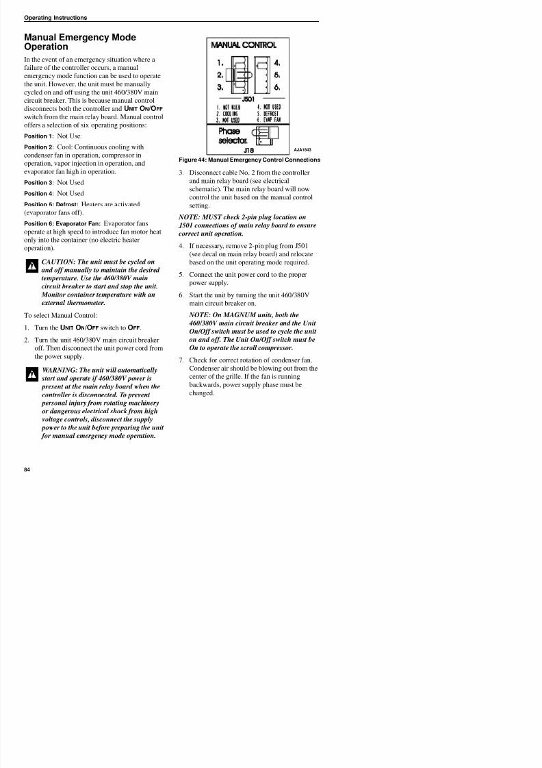
8/12/2019 Termo_King_Magnum_manual.pdf
http://slidepdf.com/reader/full/termokingmagnummanualpdf 84/194
emergency mode function can be used to operatethe unit. However, the unit must be manually
cycled on and off using the unit 460/380V main
circuit breaker. This is because manual control
disconnects both the controller and UNIT ON/OFF
switch from the main relay board. Manual control
offers a selection of six operating positions:
Position 1: Not Use:
Position 2: Cool: Continuous cooling with
condenser fan in operation, compressor in
operation, vapor injection in operation, and
evaporator fan high in operation.
Position 3: Not Used
Position 4: Not UsedPosition 5: Defrost: Heaters are activated
(evaporator fans off).
Position 6: Evaporator Fan: Evaporator fans
operate at high speed to introduce fan motor heat
only into the container (no electric heater
operation).
To select Manual Control:1. Turn the UNIT ON/OFF switch to OFF.
2. Turn the unit 460/380V main circuit breaker
off Then disconnect the unit power cord from
Figure 44: Manual Emergency Control Connections
3. Disconnect cable No. 2 from the controller
and main relay board (see electrical
schematic). The main relay board will now
control the unit based on the manual controlsetting.
NOTE: MUST check 2-pin plug location on
J501 connections of main relay board to ensure
correct unit operation.
4. If necessary, remove 2-pin plug from J501
(see decal on main relay board) and relocatebased on the unit operating mode required.
5. Connect the unit power cord to the proper
power supply.
6. Start the unit by turning the unit 460/380V
main circuit breaker on.
NOTE: On MAGNUM units, both the 460/380V main circuit breaker and the Unit
On/Off switch must be used to cycle the unit
on and off. The Unit On/Off switch must be
On to operate the scroll compressor
CAUTION: The unit must be cycled on
and off manually to maintain the desired
temperature. Use the 460/380V main
circuit breaker to start and stop the unit.
Monitor container temperature with an
external thermometer.
AJA1843
Operating Instructions
Advanced Fresh AirManagement (AFAM) System(Optional)
An advanced microprocessor controlled fresh air
AFAM Operation
The system is pre-calibrated for air exchange rates
of 0 to 280 m3 /hr. (0 to 165 ft3 /min.). The actual
door position is based on the air exchange setting
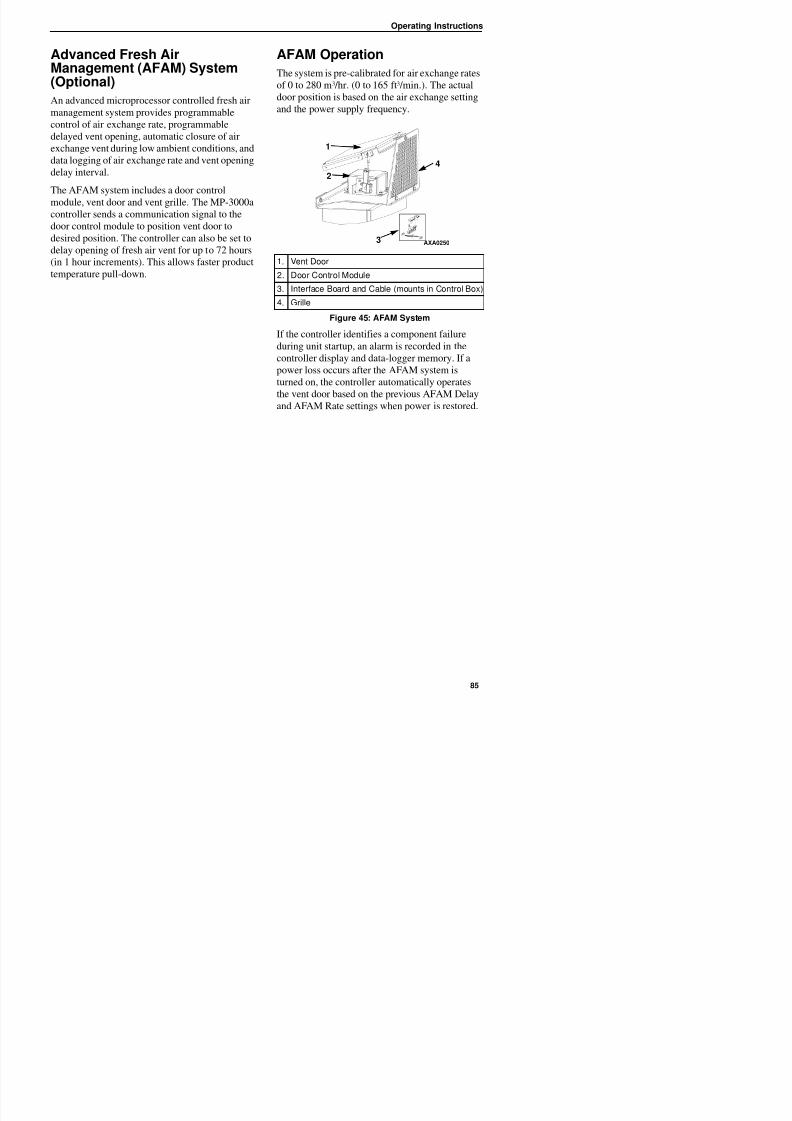
8/12/2019 Termo_King_Magnum_manual.pdf
http://slidepdf.com/reader/full/termokingmagnummanualpdf 85/194
management system provides programmable
control of air exchange rate, programmable
delayed vent opening, automatic closure of air
exchange vent during low ambient conditions, and
data logging of air exchange rate and vent opening
delay interval.
The AFAM system includes a door control
module, vent door and vent grille. The MP-3000a
controller sends a communication signal to the
door control module to position vent door to
desired position. The controller can also be set to
delay opening of fresh air vent for up to 72 hours
(in 1 hour increments). This allows faster product
temperature pull-down.
and the power supply frequency.
If the controller identifies a component failure
during unit startup, an alarm is recorded in the
controller display and data-logger memory. If a
power loss occurs after the AFAM system is
turned on, the controller automatically operates
the vent door based on the previous AFAM Delay
and AFAM Rate settings when power is restored.
1. Vent Door
2. Door Control Module
3. Interface Board and Cable (mounts in Control Box)
4. Grille
Figure 45: AFAM System
AXA0250
1
2
3
4
Operating Instructions
Vent Door Assembly
A microprocessor controlled vent door provides
programmable control of the air exchange rate.
The vent door is adjusted to the desired position
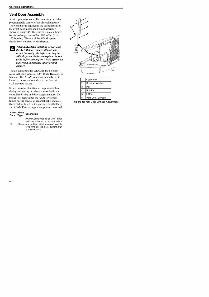
8/12/2019 Termo_King_Magnum_manual.pdf
http://slidepdf.com/reader/full/termokingmagnummanualpdf 86/194
by a vent door motor and linkage assembly,shown in Figure 46. The system is pre-calibrated
for air exchange rates of 0 to 280 m3 /hr. (0 to
165 ft3 /min.). The use of the AFAM system
should be established by the shipper.
The default setting for AFAM in the Setpoint
menu is the last value set (Off, Units, Demand, or
Manual). The AFAM submenu should be set to
Units to control the vent door to the fresh air
exchange rate setting.
If the controller identifies a component failure
during unit startup, an alarm is recorded in the
controller display and data-logger memory. If a
power loss occurs after the AFAM system is
turned on, the controller automatically operates
the vent door based on the previous AFAM Delay
and AFAM Rate settings when power is restored.
WARNING: After installing or servicing
the AFAM door, remove all tools and
install the vent grille before starting the AFAM system. Failure to replace the vent
grille before turning the AFAM system on
may result in personal injury or unit
damage.
AlarmCode
AlarmType
Description
57 Check
AFAM Control Module or Motor Error: Indicates a frozen or stuck vent door
or a problem with the control moduleor its wiring or the motor current drawis not with limits.
1. Cotter Pins
2. Shoulder Washer
3. Pin
4. Rod End
5. L-Rod
6. Vent Motor Linkage
Figure 46: Vent Door Linkage Adjustment
Operating Instructions
Starting the AFAM System
1. Press the SETPOINT key. The Setpoint menu
appears with the cursor in the [TEMP SETP]
line.
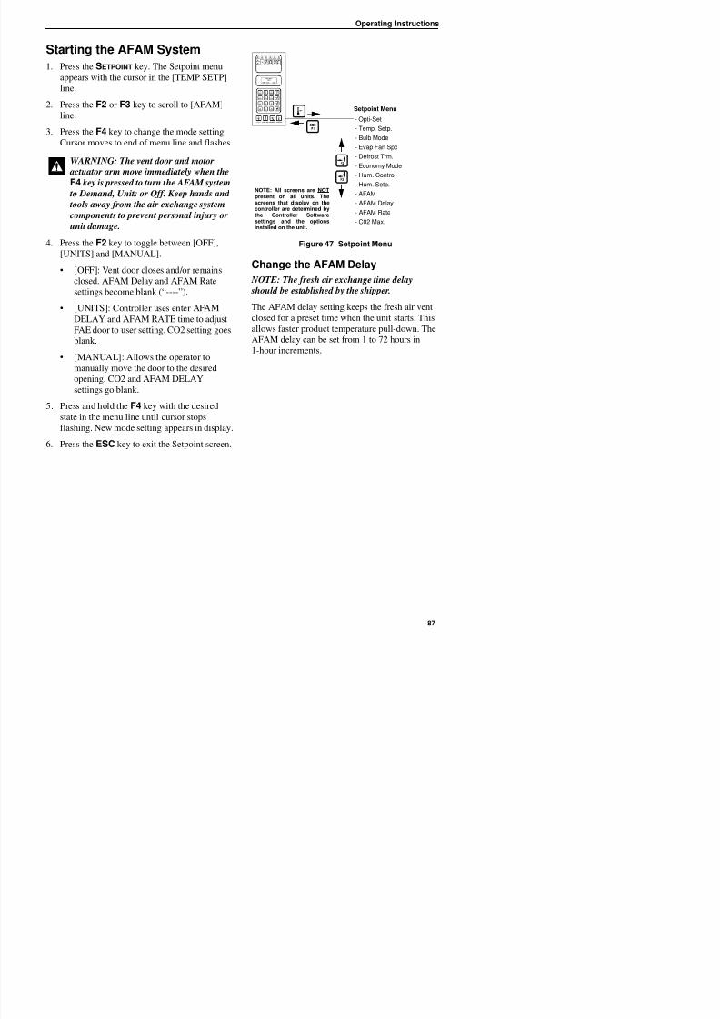
8/12/2019 Termo_King_Magnum_manual.pdf
http://slidepdf.com/reader/full/termokingmagnummanualpdf 87/194
2. Press the F2 or F3 key to scroll to [AFAM]
line.
3. Press the F4 key to change the mode setting.
Cursor moves to end of menu line and flashes.
4. Press the F2 key to toggle between [OFF],
[UNITS] and [MANUAL].
• [OFF]: Vent door closes and/or remains
closed. AFAM Delay and AFAM Rate
settings become blank (“----”).
• [UNITS]: Controller uses enter AFAM
DELAY and AFAM RATE time to adjust
FAE door to user setting. CO2 setting goes
blank.
• [MANUAL]: Allows the operator to
manually move the door to the desired
opening. CO2 and AFAM DELAY
settings go blank.
5. Press and hold the F4 key with the desired
state in the menu line until cursor stops
flashing. New mode setting appears in display.
6. Press the ESC key to exit the Setpoint screen.
Figure 47: Setpoint Menu
Change the AFAM Delay
NOTE: The fresh air exchange time delay
should be established by the shipper.
The AFAM delay setting keeps the fresh air vent
closed for a preset time when the unit starts. This
allows faster product temperature pull-down. The
AFAM delay can be set from 1 to 72 hours in1-hour increments.
WARNING: The vent door and motor
actuator arm move immediately when the
F4 key is pressed to turn the AFAM system to Demand, Units or Off. Keep hands and
tools away from the air exchange system
components to prevent personal injury or
unit damage.
Setpoint Menu
- Opti-Set
- Temp. Setp.
- Bulb Mode
- Evap Fan Spd
- Defrost Trm.
- Economy Mode
- Hum. Control
- Hum. Setp.
- AFAM
- AFAM Delay
- AFAM Rate
- C02 Max.
NOTE: All screens are NOTpresent on all units. Thescreens that display on thecontroller are determined bythe Controller Softwaresettings and the optionsinstalled on the unit.
Operating Instructions
5. Press and hold the F4 key until the cursor
stops flashing. The new time delay is recorded
in the controller and appears in the LCD
display.
6 P th ESC k t it th S t i t
1
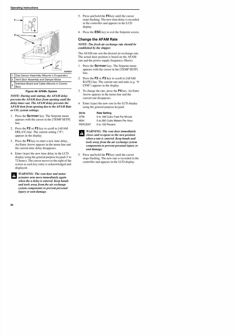
8/12/2019 Termo_King_Magnum_manual.pdf
http://slidepdf.com/reader/full/termokingmagnummanualpdf 88/194
NOTE: During unit startup, the AFAM delay
prevents the AFAM door from opening until the
delay times out. The AFAM delay prevents the
AFAM door from opening due to the AFAM Rate
or CO2 system settings.
1. Press the SETPOINT key. The Setpoint menu
appears with the cursor in the [TEMP SETP]
line.
2. Press the F2 or F3 key to scroll to [AFAM
DELAY] line. The current setting (“0”)
appears in the display.
3. Press the F4 key to enter a new time delay,.
An Enter Arrow appears in the menu line and
the current time delay disappears.
6. Press the ESC key to exit the Setpoint screen.
Change the AFAM Rate
NOTE: The fresh air exchange rate should be
established by the shipper.
The AFAM rate sets the desired air exchange rate.
The actual door position is based on the AFAM
rate and the power supply frequency (Hertz).
1. Press the SETPOINT key. The Setpoint menu
appears with the cursor in the [TEMP SETP]
line.
2. Press the F2 or F3 key to scroll to [AFAM
RATE] line. The current rate and units (e.g. “0
CFM”) appears in the display.
3. To change the rate, press the F4 key. An Enter
Arrow appears in the menu line and the
current rate disappears.
4. Enter (type) the new rate in the LCD display
using the general purpose keypad:
1. Gas Sensor Assembly (Mounts in Evaporator)
2. Vent Door Assembly and Damper Motor
3.
Interface Board and Cable (Mounts in Control
Box)
Figure 48: AFAM+ System
AXA0251
2
3
Units Rate Setting
CFM 0 to 168 Cubic Feet Per Minute
M3H 0 to 280 Cubic Meters Per Hour
PERCENT 0 to 100 Percent
WARNING: The vent door immediately
closes and re-opens to the new position
when a rate is entered. Keep hands and tools away from the air exchange system
components to prevent personal injury or
unit damage.
Operating Instructions
Advanced Fresh AirManagement Plus (AFAM+)System
An advanced microprocessor controlled fresh air
management system that provides:
1
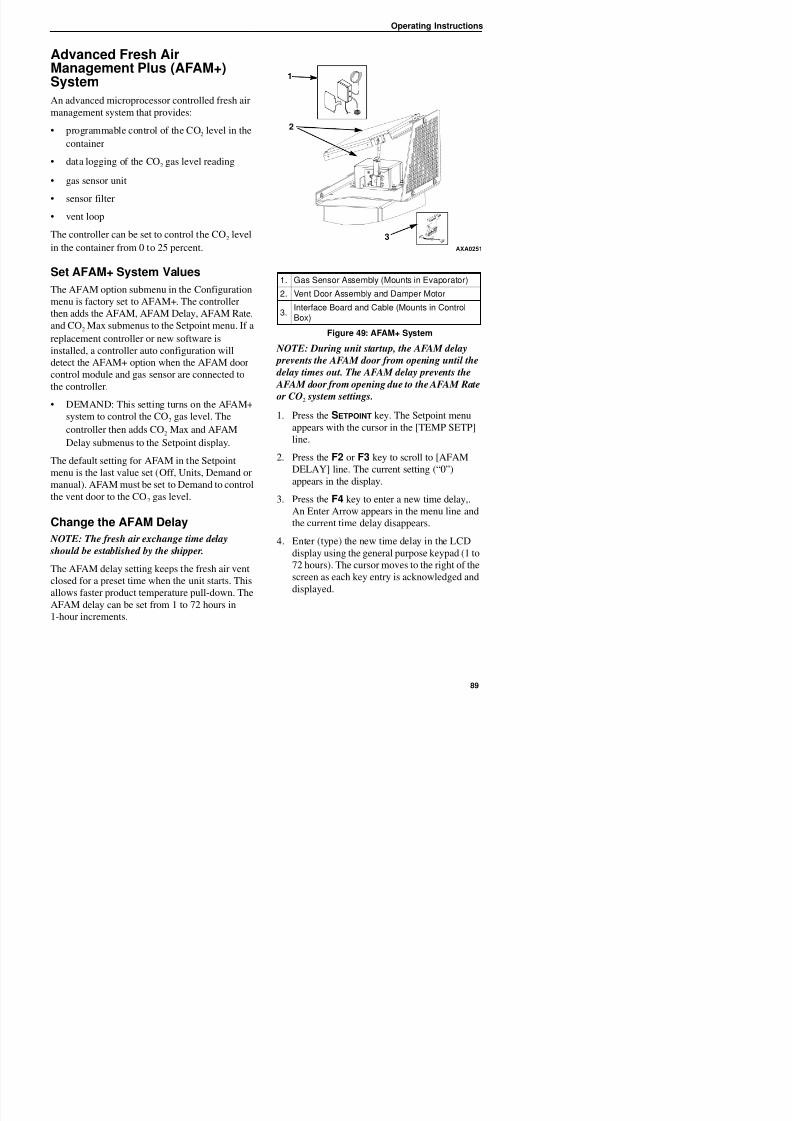
8/12/2019 Termo_King_Magnum_manual.pdf
http://slidepdf.com/reader/full/termokingmagnummanualpdf 89/194
management system that provides:
• programmable control of the CO2 level in the
container
• data logging of the CO2 gas level reading
• gas sensor unit
• sensor filter
• vent loop
The controller can be set to control the CO2 level
in the container from 0 to 25 percent.
Set AFAM+ System Values
The AFAM option submenu in the Configurationmenu is factory set to AFAM+. The controller
then adds the AFAM, AFAM Delay, AFAM Rate,
and CO2 Max submenus to the Setpoint menu. If a
replacement controller or new software is
installed, a controller auto configuration will
detect the AFAM+ option when the AFAM door
control module and gas sensor are connected tothe controller.
• DEMAND: This setting turns on the AFAM+
system to control the CO2 gas level. The
controller then adds CO2 Max and AFAM
Delay submenus to the Setpoint display.
The default setting for AFAM in the Setpointmenu is the last value set (Off, Units, Demand or
manual). AFAM must be set to Demand to control
the vent door to the CO2 gas level.
NOTE: During unit startup, the AFAM delay
prevents the AFAM door from opening until the
delay times out. The AFAM delay prevents the AFAM door from opening due to the AFAM Rate
or CO2 system settings.
1. Press the SETPOINT key. The Setpoint menu
appears with the cursor in the [TEMP SETP]
line.
2. Press the F2 or F3 key to scroll to [AFAM
DELAY] line. The current setting (“0”)appears in the display.
3. Press the F4 key to enter a new time delay,.
A E A i h li d
1. Gas Sensor Assembly (Mounts in Evaporator)
2. Vent Door Assembly and Damper Motor
3.Interface Board and Cable (Mounts in ControlBox)
Figure 49: AFAM+ System
AXA0251
2
3
Operating Instructions
WARNING: The vent door and motor
actuator arm move immediately again
when the a delay is entered. Keep hands
and tools away from the air exchange
system components to prevent personal
8/12/2019 Termo_King_Magnum_manual.pdf
http://slidepdf.com/reader/full/termokingmagnummanualpdf 90/194
5. Press and hold the F4 key until the cursor
stops flashing. The new time delay is recorded
in the controller and appears in the LCD
display.
6. Press the ESC key to exit the Setpoint screen.
Change the CO2 Minimum andMaximum Setting
NOTE: The minimum CO2 rate should be
established by the shipper.
The CO2 rate sets the desired CO2 level in the
container when a gas sensor unit is installed. Theactual AFAM door position is based on the CO2
level and AFAM delay.
1. Press the SETPOINT key. The Setpoint menu
appears with the cursor in the [TEMP SETP]
line.
2. Press the F2 or F3 key to scroll to “CO2” line.The current rate and units (e.g. “2.5 percent”)
appears in the display.
3. To change the rate, press the F4 key. An Enter
Arrow appears in the menu line and the
current rate disappears.
4. Enter (type) the new rate in the LCD display
using the general purpose keypad:
0 to 21 percent for Minimum
0 to 25 percent for Maximum
system components to prevent personalinjury or unit damage.
Operating Instructions
OPTI-SET
Automated Fresh Air Exchange Management is
designed for simple operation with the flexibility
to handle a variety of commodities and situations.
OPTI-SET allows all of the following variables to
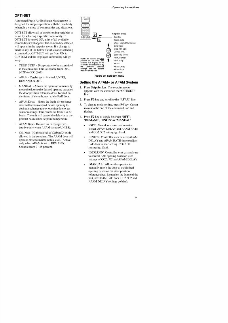
8/12/2019 Termo_King_Magnum_manual.pdf
http://slidepdf.com/reader/full/termokingmagnummanualpdf 91/194
OPTI-SET allows all of the following variables to
be set by selecting a specific commodity. If
OPTI-SET is turned ON, a list of all available
commodities will appear. The commodity selected
will appear in the setpoint menu. If a change is
made to any of the below variables after selecting
a commodity, OPTI-SET will go from ON to
CUSTOM and the displayed commodity will goaway.
• TEMP. SETP. - Temperature to be maintained
in the container. This is settable from -30C
(-22F) to 30C (86F).
• AFAM - Can be set to Manual, UNITS,
DEMAND or OFF.
• MANUAL - Allows the operator to manually
move the door to the desired opening based on
the door position reference decal located on
the frame of the unit, next to the FAE door.
• AFAM Delay - Hours the fresh air exchange
door will remain closed before opening to
desired exchange rate or opening due to gassensor readings. This can be set from 1 to 72
hours. The unit will cancel the delay once the
product has reached setpoint temperature.
• AFAM Rate - Desired air exchange rate.
(Active only when AFAM is set to UNITS).
• CO2 Max - Highest level of Carbon Dioxide
allowed in the container. The AFAM door will
open or close to maintain this level. (Active
only when AFAM is set to DEMAND.)
Settable from 0 25 percent
Figure 50: Setpoint Menu
Setting the AFAM+ or AFAM System1. Press Setpoint key. The setpoint menu
appears with the cursor on the ‘OPTISET’
line.
2. Press F3 key and scroll to the ‘AFAM’ line.
3. To change mode setting, press F4 key. Cursor
moves to the end of the command line andflashes.
4. Press F2 key to toggle between ‘OFF’,
‘DEMAND’, ‘UNITS’ or ‘MANUAL’
• ‘OFF’: Vent door closes and remains
closed. AFAM DELAY and AFAM RATE
and CO2 / O2 settings go blank.
• ‘UNITS’: Controller uses entered AFAM
DELAY and AFAM RATE time to adjust
FAE door to user setting. CO2 / O2
i bl k
Setpoint Menu
- Opti-Set
- Temp. Setp.
- Water Cooled Condenser
- Bulb Mode
- Evap Fan Spd
- Defrost Trm.
- Economy Mode
- Hum. Control
- Hum. Setp.
- AFAM
- AFAM Delay
- AFAM Rate
- C02 Max.
NOTE: All screens are NOTpresent on all units. Thescreens that display on thecontroller are determined bythe Controller Softwaresettings and the optionsinstalled on the unit.
Operating Instructions
5. With the mode setting in the menu line, press
and hold the F4 key until the cursor stops
flashing. The new mode setting will appear on
the LCD display.
6. When settings are completed, press the ESCk i h i
• Defrost Termination Temperature
• Economy Mode
• Humidity Control
• Humidity Setpoint
8/12/2019 Termo_King_Magnum_manual.pdf
http://slidepdf.com/reader/full/termokingmagnummanualpdf 92/194
6. When settings are completed, press the ESCkey to exit the setpoint menu.
Changing the AFAM+ SettingsUsing ‘OPTISET’ (sets ‘DEMAND’Mode)
1. Press Setpoint key. The setpoint menu
appears with the cursor on the ‘OPTISET’line.
2. Press F4 key. The following screen will
appear:
3. Use F2 / F3 keys to scroll to desired product.
4. Press and hold F4 key to auto enter product
settings.
5. Display will show selected product. NOTE: If any of the auto product settings
made by ‘Optiset’ are modified, the display
will now change from the selected product to
‘CUSTOM’. This signifies that some or all of
the settings have been changed.
Modify Optiset Product Settings in‘DEMAND’
1. Press Setpoint key. The setpoint menu appears
with the cursor on the ‘OPTISET’ line.
Humidity Setpoint
• AFAM DELAY
• O2 Minimum (if applicable)
• CO2 Maximum
NOTE: Do not modify any of the above
settings without direct instructions from the
shipper. Serious cargo damage could occur.
3. Example. Modifying the O2 and CO2 settings:
4. Press F3 key to scroll to ‘O2 MIN’.
5. Press F4 key to enter the setting mode.
6. Enter the O2 setting supplied by the shipper.
7. Press and hold the F4 key until the cursor
stops flashing. The new rate is recorded in the
datalogger and appears on the LCD display.
8. Press F3 key to scroll to ‘CO2 MAX’.
9. Press F4 key to enter the setting mode.
10. Enter the CO2 setting supplied by the shipper.
11. Press and hold the F4 key until the cursor
stops flashing. The new rate is recorded in the
datalogger and appears on the LCD display.
Changing the AFAM Mode to‘DEMAND’
1. Press Setpoint key. The setpoint menu appearswith the cursor on the ‘OPTISET’ line.
2. Press F3 key and scroll to the ‘AFAM’ line.
OPTISET
APPLES - GENERAL
TO ACTIVATE PRESS F4
Operating Instructions
9. Press and hold the F4 key until the cursor
stops flashing. The new rate is recorded in the
datalogger and appears on the LCD display.
NOTE: If O2 setting is applicable, use above
instructions to set O2 value.
14. Press and hold the F4 key until the cursor
stops flashing. Door will calibrate to open
position and the new rate is recorded in the
datalogger and appears on the LCD display.
Changing the AFAM Mode to
8/12/2019 Termo_King_Magnum_manual.pdf
http://slidepdf.com/reader/full/termokingmagnummanualpdf 93/194
s c o s o se O va e.
10. If ‘AFAM DELAY’ is required.
11. Press F2 key to scroll to ‘AFAM DELAY’.
12. Press F4 key to enter setting mode.
13. Enter the delay time in hours supplied by the
shipper.
14. Press and hold F4 key until cursor stops
flashing.
15. ‘CUSTOM’ will be displayed with the user
entered settings.
Changing the AFAM Mode to
‘UNITS’1. Press Setpoint key. The setpoint menu appears
with the cursor on the ‘OPTISET’ line.
2. Press F3 key and scroll to the ‘AFAM’ line.
3. Press F4 key. Cursor moves to the end of the
command line and flashes.
4. Press F2 key to toggle to ‘UNITS’.
5. With ‘UNITS’ in the menu line, press and
hold the F4 key until the cursor stops flashing.
6. If ‘AFAM DELAY’ is required.
NOTE: If delay is required, ‘AFAM DELAY’
must be set before ‘AFAM RATE’.
7. Press F2 key to scroll to ‘AFAM DELAY’.
8. Press F4 key to enter setting mode.
Changing the AFAM Mode to‘MANUAL’
1. Press Setpoint key. The setpoint menu appears
with the cursor on the ‘OPTISET’ line.
2. Press F3 key and scroll to the ‘AFAM’ line.
3. Press F4 key. Cursor moves to the end of the
command line and flashes.
4. Press F2 key to toggle to ‘MANUAL’.
5. With ‘MANUAL’ in the menu line, press and
hold the F4 key until the cursor stops flashing.
6. Press F3 key to scroll to ‘AFAM RATE’.
7. Press F4 key to enter the setting mode.
8. Enter fresh air exchange rate supplied by the
shipper.
9. Press and hold the F4 key until the cursor
stops flashing. The new rate will be recorded
in the datalogger. The following LCD screen
will appear:
10. Use F3 key to open the door or F2 key to
close the door, move FAE door opening torequired opening based on requirement from
shipper using the door position reference decal
located on the frame of the unit, next to the
MOVE DOOR TO DESIRED
POSITION USING F2 / F3
PRESS F4 TO ACCEPT
Operating Instructions
Testing AFAM+ / AFAM System
The system consists of the following main parts:
• Gas Analyzer
• Mounted in Evaporator Section
automatically during any defrost cycle. It will
re-open to the user setting once the defrost cycle
has completed. There will be no indication of
CO2 or O2 in the ‘DATA’ menu.
‘DEMAND’: Controller uses gas analyzer tocontrol FAE door open / close based on user
8/12/2019 Termo_King_Magnum_manual.pdf
http://slidepdf.com/reader/full/termokingmagnummanualpdf 94/194
p• Interface Board
• Mounted on Main Relay Board (MRB)
• Damper Motor
• Mounted above Control Box
• Vent Door Linkage
• Connects Damper Motor to Vent Door
• Vent (FAE) Door
• Opens to allow air exchange in and out of
the container
AFAM+ Option Alarm Codes (seemanual for further descriptions) –Software versions 04100100 andabove
• Code 57 – AFAM Control Module or Damper
Motor Error
• Code 68 – AFAM Gas Analyzer Error
• Code 69 – Gas Analyzer Calibration
• Code 122 – O2 Sensor Calibration Error (PTI
Only) (if equipped)
How the system works:
The way the AFAM+ feature will operate depends
on the AFAM mode selection in the setpoint
menu. If selection is:
‘OFF’: Vent door is closed and remains closed.
g ycontrol FAE door open / close based on user
settings of CO2 and O2 (if equipped) and AFAM
DELAY. The FAE door will not open until the
container temperature is ‘In Range’ of setpoint
regardless of the CO2 and O2 (if applicable)
readings. If the door is closed, verify that the CO2
is not above CO2 setpoint and the O2 (if
equipped) is not below O2 setpoint. The FAE door
will open after the AFAM DELAY (if any) has
expired. The FAE door will close automatically
during any defrost cycle. The gas sensor readings
are updated every 15 minutes. There will be active
CO2 and O2 (if applicable) readings in the
‘DATA’ menu
‘MANUAL’: Allows the operator to manually
move the door to the desired opening based on the
door position reference decal located on the frame
of the unit, next to the FAE door. There will be no
indication of CO2 or O2 in the ‘DATA’ menu.
How to verify System Operation
If the system appears not to be operating properly,
it is best to verify that the controller can recognize
if the AFAM+ option is installed. Use the ‘Auto
Config’ function found in the ‘Configuration’
menu. Select setting to ON. Allow the
configuration steps to complete. The last step of
the configuration will be AFAM. Watch the LCD
display closely during this test. When to AFAMdoor opens and closes, the AFAM option will be
set. The controller will now test communications
to the gas analyzer. When the gas analyzer is
Operating Instructions
To select ‘Auto Config’ to ON:
1. Enter ‘Configuration’ menu.
2. Use F2 or F3 key to scroll to ‘Auto Config’
menu line.
3 Press F4 The password line appears
7. Press ESC key to begin the ‘Auto Config’
sequence.
Once the ‘Auto Config’ is complete, and the
AFAM+ system has been found and configured
into controller memory, enter the desired settings.
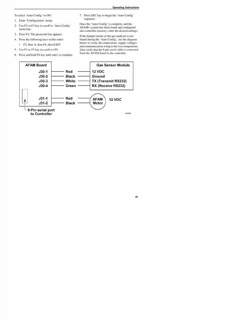
8/12/2019 Termo_King_Magnum_manual.pdf
http://slidepdf.com/reader/full/termokingmagnummanualpdf 95/194
3. Press F4. The password line appears.
4. Press the following keys in this order:
• F2, then A, then F4, then EXIT
5. Use F2 or F3 key to scroll to ON.
6. Press and hold F4 key until entry is complete.
If the damper motor or the gas analyzer is not
found during the ‘Auto Config’, use the diagram
below to verify the connections, supply voltages
and communication wring to the two components.
Also verify that the 9-pin serial cable is connected
from the AFAM board to the controller.
Operating Instructions
Alarm Codes and Actions / Data Menu Display
There are three (3) possible alarm codes that can
be generated if the AFAM+ system is not working
properly. There is one (1) additional PTI alarm
that could be generated on a unit equipped /utilizing an O2 sensor
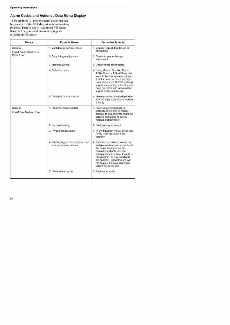
8/12/2019 Termo_King_Magnum_manual.pdf
http://slidepdf.com/reader/full/termokingmagnummanualpdf 96/194
utilizing an O2 sensor.
Alarms Possible Cause Corrective Action(s)
Code 57
AFAM Control Module orMotor Error
1. Vent door is frozen or stuck 1. Visually inspect door for ice orobstruction
2. Door linkage adjustment 2. Check for proper linkageadjustment
3. Incorrect wiring 3. Check wiring connections
4. Defective motor 4. Using Manual Function Test –AFAM Open or AFAM Close, testto cycle the door open and closed.If motor does not move the door,use independent 12 VDC (battery)supply to cycle the motor. If motordoes not move with independentsupply, motor is defective
5. Defective control module 5. If motor cycles using independent12 VDC supply, the control moduleis faulty
Code 68
AFAM Gas Analyzer Error
1. Analyzer disconnected 1. Verify analyzer harness iscorrectly connected to controlmodule, to gas analyzer and 9-pincable is connected to controlmodule and controller
2. Incorrect wiring 2. Verify wiring is correct
3. Wrong configuration 3. In Configuration menu, check thatAFAM+ configuration is setproperly
4. Cable plugged into download portduring sampling interval
4. Both the controller download portand gas analyzer are connected toth i l t th
Operating Instructions
Code 69
Gas Analyzer Calibration
(Normal)
1. Stale atmosphere / Filter or inlet /outlet tubes restricted (SEE NOTEBELOW)
1. Open evaporator access door orfully open vent door and allow unitto operate on high speed fan for
20 to 30 minutes to purge any old,stale air trapped in the analyzer
Alarms Possible Cause Corrective Action(s)
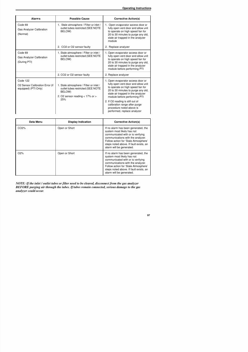
8/12/2019 Termo_King_Magnum_manual.pdf
http://slidepdf.com/reader/full/termokingmagnummanualpdf 97/194
stale air trapped in the analyzermodule
2. CO2 or O2 sensor faulty 2. Replace analyzer
Code 69
Gas Analyzer Calibration
(During PTI)
1. Stale atmosphere / Filter or inlet /outlet tubes restricted (SEE NOTEBELOW)
1. Open evaporator access door orfully open vent door and allow unitto operate on high speed fan for
20 to 30 minutes to purge any old,stale air trapped in the analyzermodule before performing PTI
2. CO2 or O2 sensor faulty 2. Replace analyzer
Code 122
O2 Sensor Calibration Error (ifequipped) (PTI Only)
1. Stale atmosphere / Filter or inlet /outlet tubes restricted (SEE NOTE
BELOW)
2. O2 sensor reading < 17% or >25%
1. Open evaporator access door orfully open vent door and allow unitto operate on high speed fan for
20 to 30 minutes to purge any old,stale air trapped in the analyzermodule before performing PTI
2. If O2 reading is still out ofcalibration range after purgeprocedure noted above isperformed, replace analyzer
Data Menu Display Indication Corrective Action(s)
CO2% Open or Short If no alarm has been generated, thesystem most likely has notcommunicated with or is verifyingcommunications with the analyzer.Follow action for ‘Stale Atmosphere’steps noted above. If fault exists, an
alarm will be generated.
O2% Open or Short If no alarm has been generated, thesystem most likely has notcommunicated with or is verifying
Operating Instructions
Vent Door Calibration andLinkage Adjustment
Vent Door Calibration
The positioning of the vent door is controlledbased on a timing algorithm in the controller The
• L-Rod movement in shoulder washer free
• Ball joint movement in rod end free
• Door can be adjusted as required by loosening
the bolts on the back wall. Adjustment can be
made vertically and horizontally. Ifadjustment is done on the door ensure the
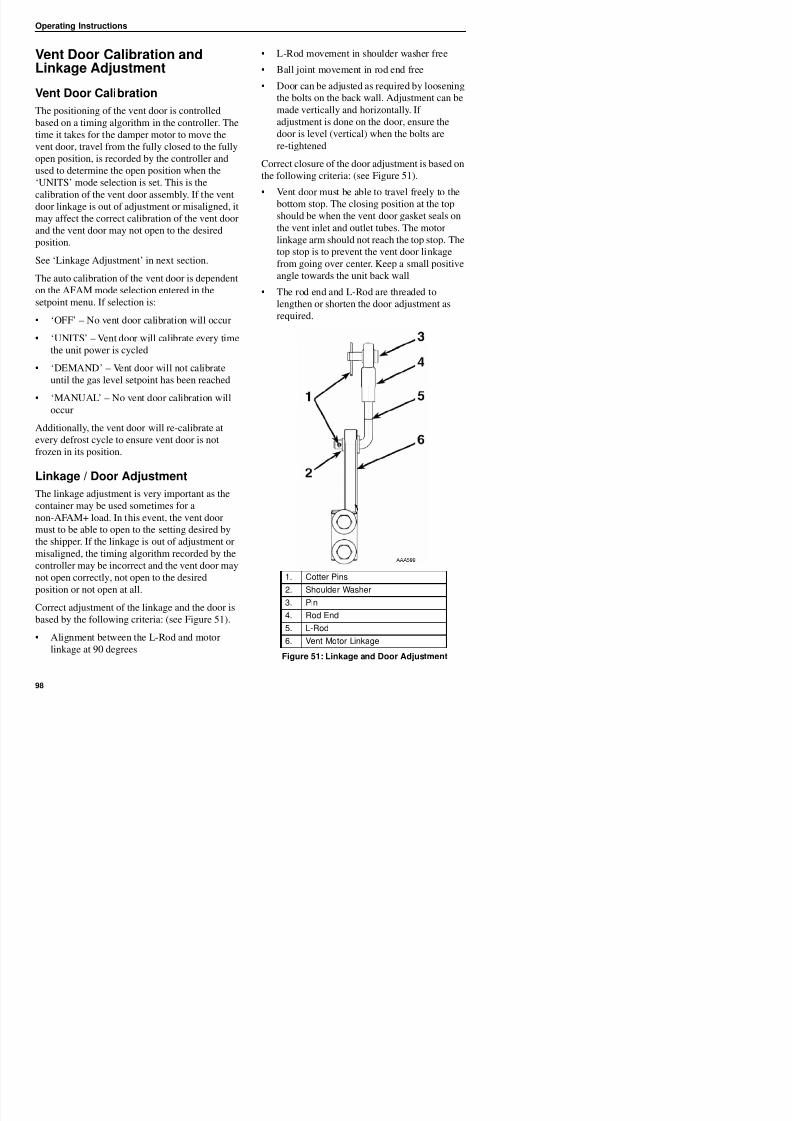
8/12/2019 Termo_King_Magnum_manual.pdf
http://slidepdf.com/reader/full/termokingmagnummanualpdf 98/194
based on a timing algorithm in the controller. The
time it takes for the damper motor to move the
vent door, travel from the fully closed to the fully
open position, is recorded by the controller and
used to determine the open position when the
‘UNITS’ mode selection is set. This is the
calibration of the vent door assembly. If the vent
door linkage is out of adjustment or misaligned, it
may affect the correct calibration of the vent door
and the vent door may not open to the desired
position.
See ‘Linkage Adjustment’ in next section.
The auto calibration of the vent door is dependent
on the AFAM mode selection entered in thesetpoint menu. If selection is:
• ‘OFF’ – No vent door calibration will occur
• ‘UNITS’ – Vent door will calibrate every time
the unit power is cycled
• ‘DEMAND’ – Vent door will not calibrate
until the gas level setpoint has been reached
• ‘MANUAL’ – No vent door calibration will
occur
Additionally, the vent door will re-calibrate at
every defrost cycle to ensure vent door is not
frozen in its position.
Linkage / Door Adjustment
The linkage adjustment is very important as the
container may be used sometimes for a
adjustment is done on the door, ensure the
door is level (vertical) when the bolts are
re-tightened
Correct closure of the door adjustment is based on
the following criteria: (see Figure 51).
• Vent door must be able to travel freely to the
bottom stop. The closing position at the top
should be when the vent door gasket seals on
the vent inlet and outlet tubes. The motor
linkage arm should not reach the top stop. The
top stop is to prevent the vent door linkage
from going over center. Keep a small positive
angle towards the unit back wall
• The rod end and L-Rod are threaded tolengthen or shorten the door adjustment as
required.
Operating Instructions
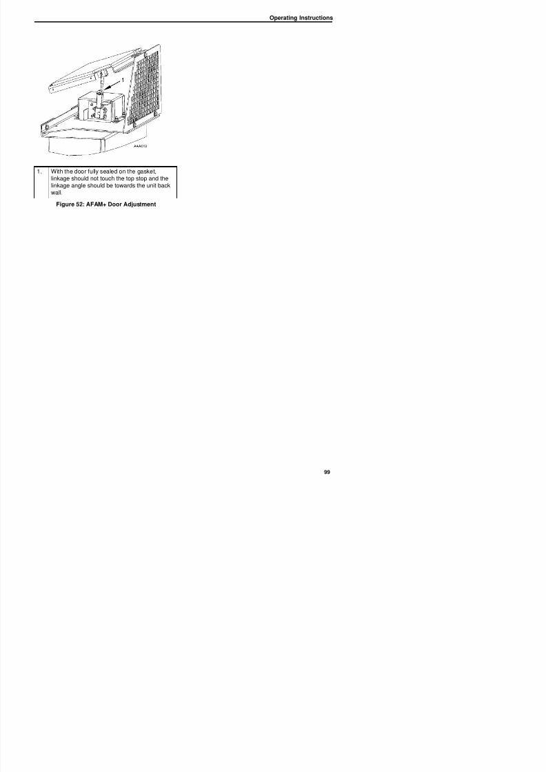
8/12/2019 Termo_King_Magnum_manual.pdf
http://slidepdf.com/reader/full/termokingmagnummanualpdf 99/194
1. With the door fully sealed on the gasket,linkage should not touch the top stop and thelinkage angle should be towards the unit backwall.
Figure 52: AFAM+ Door Adjustment
Operating Instructions
Fresh Air Exchange Recorder(Optional)
The Fresh Air Exchange Recorder detects vent
disk movement and automatically displays a value
on the LCD display.This value is also logged inthe datalogger. The entry records the time, date
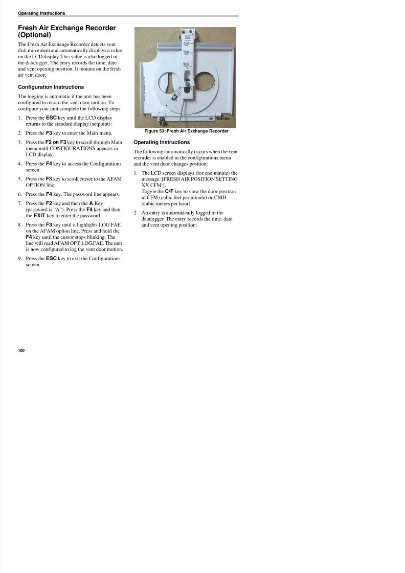
8/12/2019 Termo_King_Magnum_manual.pdf
http://slidepdf.com/reader/full/termokingmagnummanualpdf 100/194
the datalogger. The entry records the time, date
and vent opening position. It mounts on the fresh
air vent door.
Configuration Instructions
The logging is automatic if the unit has been
configured to record the vent door motion. Toconfigure your unit complete the following steps:
1. Press the ESC key until the LCD display
returns to the standard display (setpoint):
2. Press the F3 key to enter the Main menu.
3. Press the F2 OR F3 key to scroll through Main
menu until CONFIGURATIONS appears inLCD display.
4. Press the F4 key to access the Configurations
screen.
5. Press the F3 key to scroll cursor to the AFAM
OPTION line.
6. Press the F4 key. The password line appears.
7. Press the F2 key and then the A Key
(password is “A”). Press the F4 key and then
the EXIT key to enter the password.
8. Press the F3 key until it highlights LOG.FAE
on the AFAM option line. Press and hold the
F4 key until the cursor stops blinking. Theline will read AFAM OPT. LOG.FAE. The unit
is now configured to log the vent door motion.
9. Press the ESC key to exit the Configurations
Figure 53: Fresh Air Exchange Recorder
Operating Instructions
The following automatically occurs when the vent
recorder is enabled in the configurations menu
and the vent door changes position:
1. The LCD screen displays (for one minute) the
message: [FRESH AIR POSITION SETTING
XX CFM:].
Toggle the C/F key to view the door positionin CFM (cubic feet per minute) or CMH
(cubic meters per hour).
2. An entry is automatically logged in the
datalogger. The entry records the time, date
and vent opening position.
AJA1964
Operating Instructions
Electronic Chart Recorder forMP3000a Controllers
An Electronic Temperature Chart Recorder is
available for use in the MP-3000a controlled
units. The recorder connects to the controllerthrough a RS-485 port on the side of the
6. Route recorder cable, loose wire end, through
grommet in bottom of recorder enclosure and
Timmerman clamp on recorder. Ensure
exposed length is enough to reach recorder
connections.
7. Connect cable to recorder as shown below.
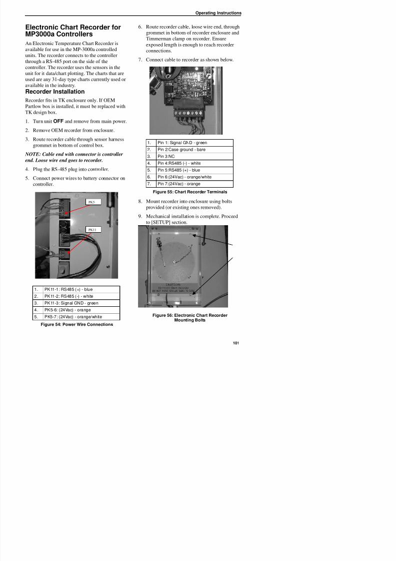
8/12/2019 Termo_King_Magnum_manual.pdf
http://slidepdf.com/reader/full/termokingmagnummanualpdf 101/194
g p
controller. The recorder uses the sensors in the
unit for it data/chart plotting. The charts that are
used are any 31-day type charts currently used or
available in the industry.
Recorder Installation
Recorder fits in TK enclosure only. If OEMPartlow box is installed, it must be replaced with
TK design box.
1. Turn unit OFF and remove from main power.
2. Remove OEM recorder from enclosure.
3. Route recorder cable through sensor harness
grommet in bottom of control box.
NOTE: Cable end with connector is controller
end. Loose wire end goes to recorder.
4. Plug the RS-485 plug into controller.
5. Connect power wires to battery connector on
controller.
Figure 55: Chart Recorder Terminals
8. Mount recorder into enclosure using bolts
provided (or existing ones removed).
9. Mechanical installation is complete. Proceed
to [SETUP] section.
PK11
PK5
1. Pin 1: Signal GND - green
2. Pin 2:Case ground - bare
3. Pin 3:NC
4. Pin 4:RS485 (-) - white
5. Pin 5:RS485 (+) - blue
6. Pin 6:(24Vac) - orange/white
7. Pin 7:(24Vac) - orange
Operating Instructions
Recorder Setup
Once the recorder is installed, it needs to be added
to the unit configuration. Connect unit to main
power and turn ON.
NOTE: Software version 01122300 or above isrequired to add the electronic recorder.
7. Controller will now enter [AUTO CONFIG]
test as unit configuration has been changed.
8. Setup is complete upon completion of [AUTO
CONFIG] test.
Using Special Features
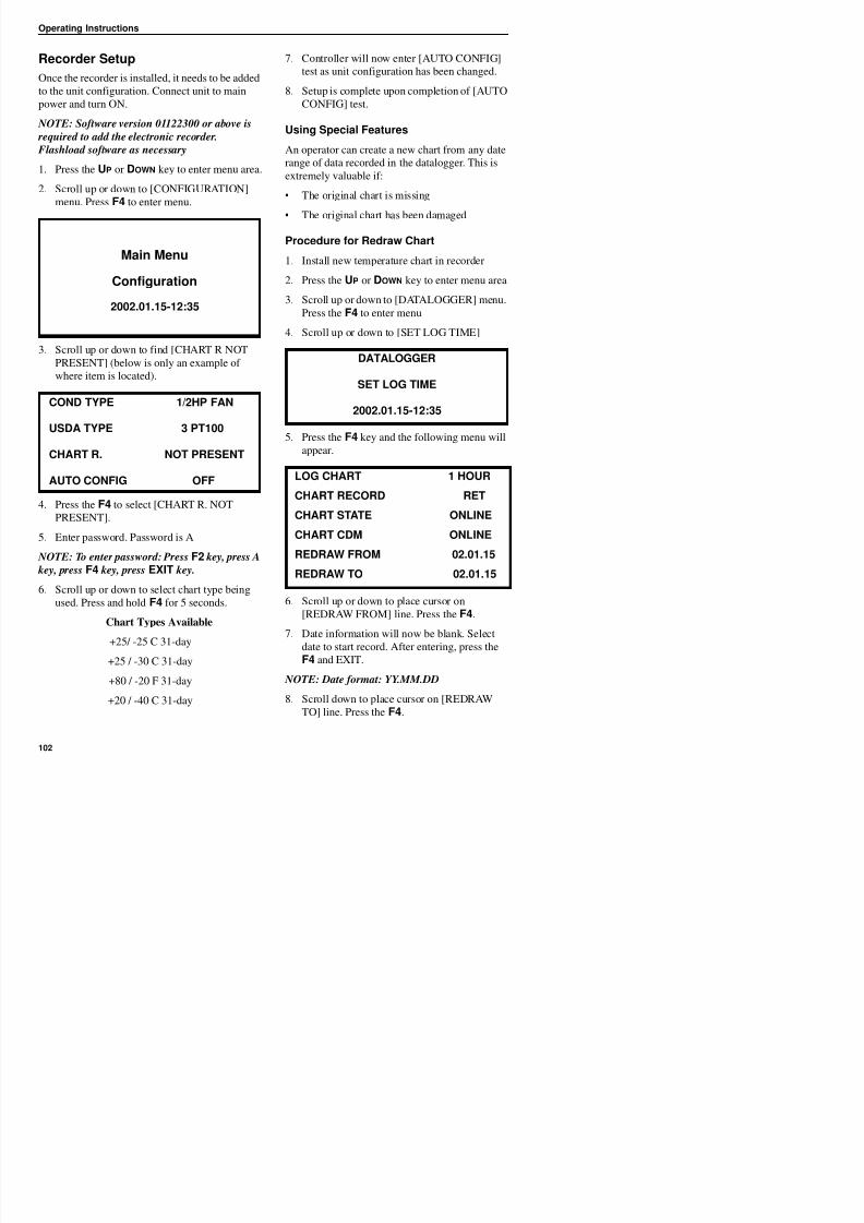
8/12/2019 Termo_King_Magnum_manual.pdf
http://slidepdf.com/reader/full/termokingmagnummanualpdf 102/194
required to add the electronic recorder.
Flashload software as necessary
1. Press the UP or DOWN key to enter menu area.
2. Scroll up or down to [CONFIGURATION]
menu. Press F4 to enter menu.
3. Scroll up or down to find [CHART R NOT
PRESENT] (below is only an example of
where item is located).
4. Press the F4 to select [CHART R. NOT
PRESENT].
5. Enter password. Password is A
NOTE T t d P F2 k A
An operator can create a new chart from any date
range of data recorded in the datalogger. This is
extremely valuable if:
• The original chart is missing
• The original chart has been damaged
Procedure for Redraw Chart
1. Install new temperature chart in recorder
2. Press the UP or DOWN key to enter menu area
3. Scroll up or down to [DATALOGGER] menu.
Press the F4 to enter menu4. Scroll up or down to [SET LOG TIME]
5. Press the F4 key and the following menu will
appear.
Main Menu
Configuration
2002.01.15-12:35
COND TYPE 1/2HP FAN
USDA TYPE 3 PT100
CHART R. NOT PRESENT
AUTO CONFIG OFF
DATALOGGER
SET LOG TIME
2002.01.15-12:35
LOG CHART 1 HOUR
CHART RECORD RET
CHART STATE ONLINE
CHART CDM ONLINE
REDRAW FROM 02 01 15
Operating Instructions
9. Date information will now be blank. Select
date to end record. After entering, press the F4
and EXIT.
NOTE: Date format: YY.MM.DD.
NOTE: Do not exceed 31 days. This is the limit of the chart.
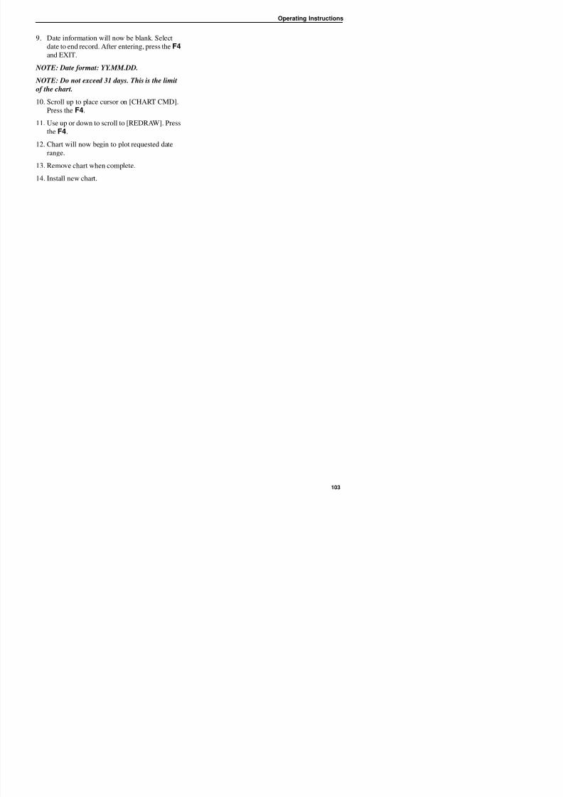
8/12/2019 Termo_King_Magnum_manual.pdf
http://slidepdf.com/reader/full/termokingmagnummanualpdf 103/194
f
10. Scroll up to place cursor on [CHART CMD].
Press the F4.
11. Use up or down to scroll to [REDRAW]. Press
the F4.
12. Chart will now begin to plot requested daterange.
13. Remove chart when complete.
14. Install new chart.
Operating Instructions

8/12/2019 Termo_King_Magnum_manual.pdf
http://slidepdf.com/reader/full/termokingmagnummanualpdf 104/194
Operating Theory
Chill Loads: (Setpoint at -9.9 C[14.1 F] and Above)
The unit operates on Cool with Modulation and
Heat to provide accurate control of chill loads.During Cool with Modulation, the controller uses
ti l i t l d i ti (PID)
Frozen Loads: (Setpoint at -10 C[14 F] and Below)
The unit operates on Full Cool and Null to
provide accurate control of frozen cargo. Thecontroller uses the return air sensor temperature
d t i t t t t l t it
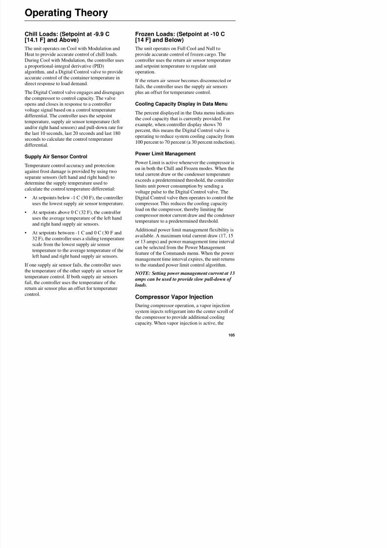
8/12/2019 Termo_King_Magnum_manual.pdf
http://slidepdf.com/reader/full/termokingmagnummanualpdf 105/194
a proportional-integral derivative (PID)
algorithm, and a Digital Control valve to provide
accurate control of the container temperature in
direct response to load demand.
The Digital Control valve engages and disengages
the compressor to control capacity. The valveopens and closes in response to a controller
voltage signal based on a control temperature
differential. The controller uses the setpoint
temperature, supply air sensor temperature (left
and/or right hand sensors) and pull-down rate for
the last 10 seconds, last 20 seconds and last 180
seconds to calculate the control temperature
differential.
Supply Air Sensor Control
Temperature control accuracy and protection
against frost damage is provided by using two
separate sensors (left hand and right hand) to
determine the supply temperature used to
calculate the control temperature differential:
• At setpoints below -1 C (30 F), the controller
uses the lowest supply air sensor temperature.
• At setpoints above 0 C (32 F), the controller
uses the average temperature of the left hand
and right hand supply air sensors.
• At setpoints between -1 C and 0 C (30 F and
32 F), the controller uses a sliding temperature
scale from the lowest supply air sensor
and setpoint temperature to regulate unit
operation.
If the return air sensor becomes disconnected or
fails, the controller uses the supply air sensors
plus an offset for temperature control.
Cooling Capacity Display in Data Menu
The percent displayed in the Data menu indicates
the cool capacity that is currently provided. For
example, when controller display shows 70
percent, this means the Digital Control valve is
operating to reduce system cooling capacity from
100 percent to 70 percent (a 30 percent reduction).
Power Limit Management
Power Limit is active whenever the compressor is
on in both the Chill and Frozen modes. When the
total current draw or the condenser temperature
exceeds a predetermined threshold, the controller
limits unit power consumption by sending avoltage pulse to the Digital Control valve. The
Digital Control valve then operates to control the
compressor. This reduces the cooling capacity
load on the compressor, thereby limiting the
compressor motor current draw and the condenser
temperature to a predetermined threshold.
Additional power limit management flexibility isavailable. A maximum total current draw (17, 15
or 13 amps) and power management time interval
can be selected from the Power Management
Operating Theory
controller energizes the vapor injection valve
continuously. The controller activates vapor
injection when the:
• Chill or Power Limit Mode: When the cool
capacity is 100 percent (in the Data menudisplay), the controller energizes the vapor
injection valve continuously.
Economy Mode Operation
The Economy mode reduces unit power
consumption by reducing evaporator fan
operation on both chill and frozen loads. The use
of the Economy mode should be established bythe shipper and the type of cargo. The Economy
mode option is turned on from Setpoint menu of
8/12/2019 Termo_King_Magnum_manual.pdf
http://slidepdf.com/reader/full/termokingmagnummanualpdf 106/194
injection valve continuously.
• Compressor discharge temperature exceeds
138 C (280 F). Vapor injection stops when the
compressor discharge temperature decreases 6
C (10.7 F).
High Temperature Protection
If the discharge gas temperature rises above 148 C
(298 F), the unit stops immediately. The controller
turns on the Alarm LED and records Alarm Code
56 (Compressor Temperature Too High). The
controller will restart the unit when the sensor
temperature is below 90 C (194 F).
Power Limit Mode
The controller uses the total unit current and the
condenser temperature to provide power limit
control in both the Chill and Frozen modes. When
the unit is on water-cooled operation, power limit
control is based on the total unit current drawonly.
Evaporator Fan Control
The controller determines evaporator fan motor
speed based on the setpoint temperature and the
Economy mode setting.
Chill Loads (Setpoints of -9.9 C [14.1 F] andAbove)
When the Economy mode is set to Off, the
mode option is turned on from Setpoint menu of
the controller.
NOTE: Enter Setpoint temperature before
turning on the Economy mode. The controller
automatically turns the Economy mode off when
the setpoint is changed.
• Chill Loads (Setpoints of -9.9 C [14.1 F]
and Above): When the temperature is
In-range, the controller shifts the evaporator
fans to low speed.
NOTE: On Chill loads, container air
temperatures may vary 1 C to 3 C (1.8 F to
5.4 F) above setpoint in high ambient temperatures.
• Frozen Loads (Setpoints of -10 C [14 F] and
Below): When the unit is in the Null mode,
the controller stops the evaporator fans. A null
state timer automatically re-starts the
evaporator fans on low speed for 5 minutes
every 45 minutes.
The Economy mode also modifies the temperature
control algorithm on frozen loads to extend the
Null mode. The unit continues on Cool operation
until return air temperature reaches ECMIN
temperature. Default ECMIN setting is 2.0 C
(3.6 F) below setpoint. ECMIN temperature is
adjustable from 0 to 5 C (0 to 8.9 F) belowsetpoint through the Configuration menu of the
controller.
Operating Theory
Condenser Fan Control
The controller also uses a proportional-integral
derivative algorithm to control the condenser
temperature and ensure a constant liquid pressure
at the expansion valve. The condenser fan
operates continuously in high ambients. In low
ambient conditions, the controller pulses the
Setting a Bulb mode fan speed automatically
activates the defrost termination temperature
setting and the Dehumidify mode (controller sets
Humidity control to DEHUM). The use of the
Bulb mode should be established by the shipper.
NOTE: If the Bulb mode is set to On, the
controller LCD display will show “BULB” and
8/12/2019 Termo_King_Magnum_manual.pdf
http://slidepdf.com/reader/full/termokingmagnummanualpdf 107/194
, p
condenser fan on and off to maintain a minimum
condenser temperature. The controller maintains a
minimum 30 C (86 F) condenser temperature on
Chill loads and a minimum 20 C (68 F) condenser
temperature on Frozen loads.
Probe Test
The controller constantly monitors the left hand
and right hand supply sensors, return sensor and
defrost (evaporator coil) sensor to determine when
to initiate a demand defrost. If a demand defrost is
requested and defrost has occurred within last 90
minutes, the controller initiates a probe test tocheck for a defective sensor.
During a Probe test, the LCD display shows
“PROBE TEST PLEASE WAIT”. The controller
operates the unit on high speed evaporator fans
only for 5 minutes. All sensor temperatures are
then compared:
• Sensors with large temperature differences are
discarded from the control algorithm. The
controller then activates the appropriate Alarm
codes to identify the defective sensor(s).
• If no sensors are found defective, controller
LCD display shows “RUNNING WITH
HIGH SUPPLY DIFFERENCE” message.Sensor errors recorded during a probe test are
cleared when the next Defrost is initiated or UNIT ON/OFF switch is turned OFF
p y
current humidity setpoint.
Dehumidify Mode
During Chill mode operation, a dehumidification
system is available to reduce the relative humidity
in the container to the desired humidity setpoint.
The Dehumidify mode option is turned on from
Setpoint menu of the controller. The relative
humidity setpoint can be set from 60 to 99 percent
from the Setpoint menu.
NOTE: The use of the Dehumidify mode should
be established by the shipper.
Changing the humidity control from off to
DEHUM in the setpoint menu activates the
dehumidify control algorithm. When the
Dehumidify mode is on, the supply air
temperature must be in-range to activate
dehumidification:
• When the humidity level is 2 percent or moreabove setpoint and the Digital Control valve
has reduced the unit cooling capacity to 85
percent, the controller pulses the electric
heaters on and off. This increases the cooling
load on the evaporator coil, thereby causing
the coil to become even colder and condense
more moisture from the container air.
Operating Theory
Continuous Temperature ControlOperation
Chill Loads (Controller Setpoint at -9.9 C[14.1 F] and Above):
The controller regulates the compressor, Digital
Control valve and electric heaters based on a
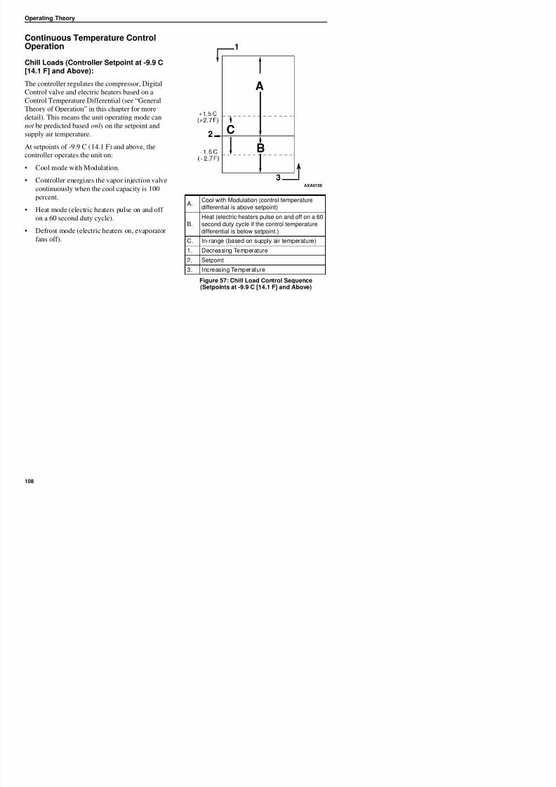
8/12/2019 Termo_King_Magnum_manual.pdf
http://slidepdf.com/reader/full/termokingmagnummanualpdf 108/194
Control Temperature Differential (see “General
Theory of Operation” in this chapter for more
detail). This means the unit operating mode can
not be predicted based only on the setpoint and
supply air temperature.
At setpoints of -9.9 C (14.1 F) and above, the
controller operates the unit on:
• Cool mode with Modulation.
• Controller energizes the vapor injection valve
continuously when the cool capacity is 100
percent.
• Heat mode (electric heaters pulse on and off
on a 60 second duty cycle).
• Defrost mode (electric heaters on, evaporator
fans off).
A.Cool with Modulation (control temperaturedifferential is above setpoint)
B.Heat (electric heaters pulse on and off on a 60second duty cycle if the control temperaturedifferential is below setpoint.)
C. In-range (based on supply air temperature)
1. Decreasing Temperature
2. Setpoint
3. Increasing Temperature
Figure 57: Chill Load Control Sequence(Setpoints at -9.9 C [14.1 F] and Above)
AXA0156
Operating Theory
MAGNUM Operating Mode Function Chart
Chill LoadsSetpoints at -9.9 C(14.4 F) and Above
Frozen LoadsSetpoints at -10 C(14 F) and Below
Cool w/Mod Heat Defrost Cool Null Defrost Unit Function•1 • Evaporator Fans High Speed1
•1 • •1 Evaporator Fans Low Speed1
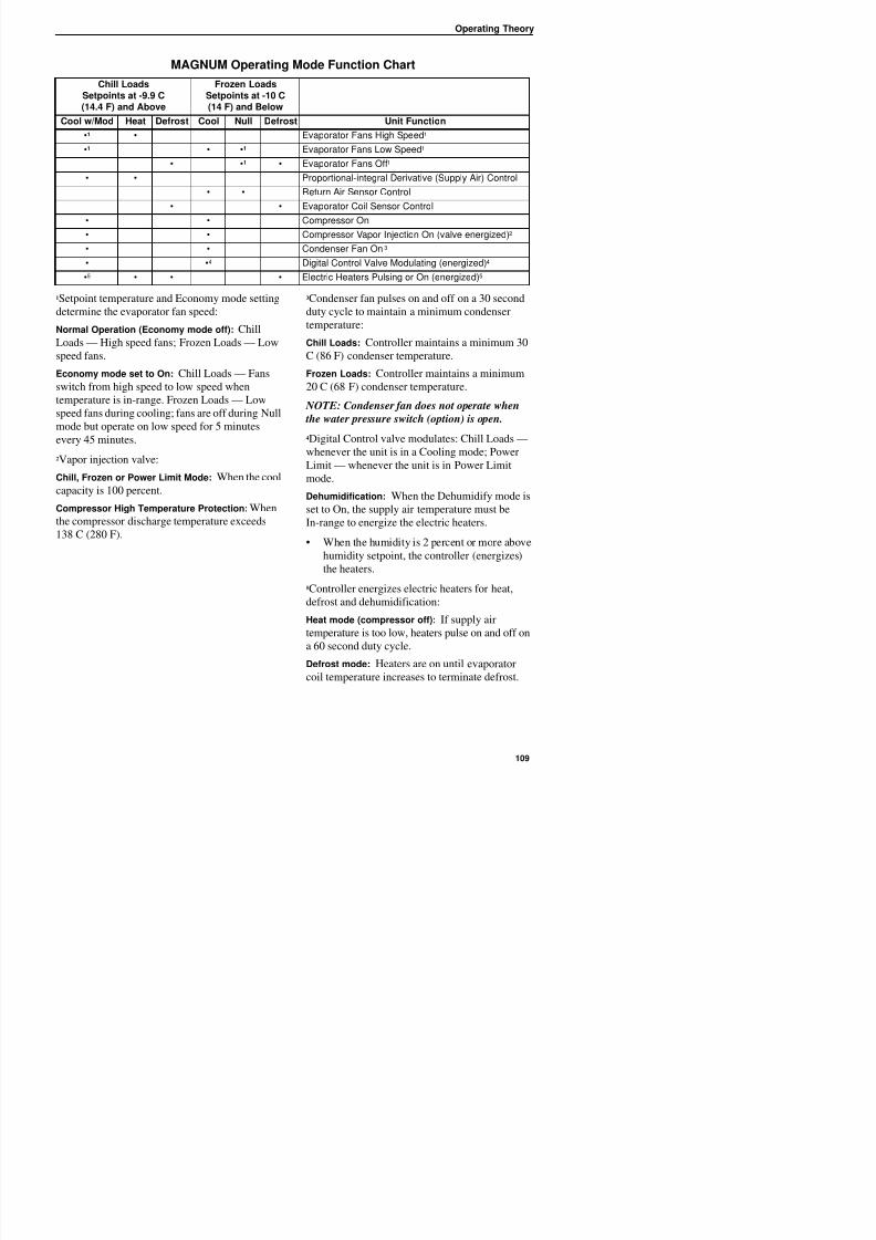
8/12/2019 Termo_King_Magnum_manual.pdf
http://slidepdf.com/reader/full/termokingmagnummanualpdf 109/194
1Setpoint temperature and Economy mode setting
determine the evaporator fan speed:
Normal Operation (Economy mode off): Chill
Loads — High speed fans; Frozen Loads — Low
speed fans.
Economy mode set to On: Chill Loads — Fans
switch from high speed to low speed when
temperature is in-range. Frozen Loads — Low
speed fans during cooling; fans are off during Null
mode but operate on low speed for 5 minutes
every 45 minutes.
2Vapor injection valve:
Chill, Frozen or Power Limit Mode: When the cool
capacity is 100 percent.
Compressor High Temperature Protection: When
the compressor discharge temperature exceeds138 C (280 F).
3Condenser fan pulses on and off on a 30 second
duty cycle to maintain a minimum condenser
temperature:
Chill Loads: Controller maintains a minimum 30
C (86 F) condenser temperature.
Frozen Loads: Controller maintains a minimum
20 C (68 F) condenser temperature.
NOTE: Condenser fan does not operate when
the water pressure switch (option) is open.4Digital Control valve modulates: Chill Loads —
whenever the unit is in a Cooling mode; Power
Limit — whenever the unit is in Power Limit
mode.
Dehumidification: When the Dehumidify mode is
set to On, the supply air temperature must be
In-range to energize the electric heaters.
• When the humidity is 2 percent or more above
humidity setpoint, the controller (energizes)
Evaporator Fans Low Speed
• •1 • Evaporator Fans Off1
• • Proportional-integral Derivative (Supply Air) Control
• • Return Air Sensor Control
• • Evaporator Coil Sensor Control
• • Compressor On• • Compressor Vapor Injection On (valve energized)2
• • Condenser Fan On 3
• •4 Digital Control Valve Modulating (energized)4
•5 • • • Electric Heaters Pulsing or On (energized)5
Operating Theory
Cool with Modulation
• Controller calls for the Cool mode whenever
the Control Temperature Differential (based
on supply air temperature) is above setpoint.
• Controller turns on the Compressor LEDwhen the compressor is operating.
Frozen Loads (Controller Setpointat -10 C [14 F] and Below):
At setpoints of -10 C (14 F) and below, the
controller locks out the Modulation and Heat
modes. The controller regulates compressor
operation based the return air sensor and setpoint
temperatures.
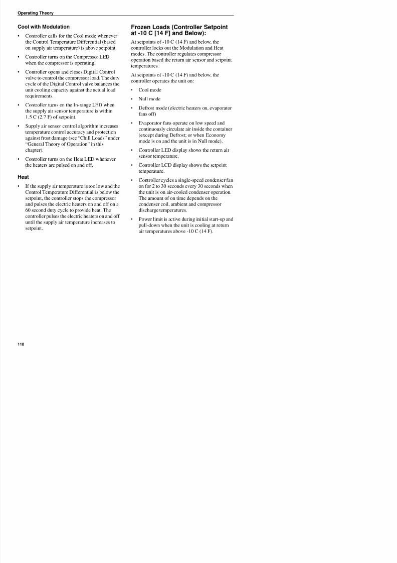
8/12/2019 Termo_King_Magnum_manual.pdf
http://slidepdf.com/reader/full/termokingmagnummanualpdf 110/194
• Controller opens and closes Digital Control
valve to control the compressor load. The duty
cycle of the Digital Control valve balances the
unit cooling capacity against the actual load
requirements.
• Controller turns on the In-range LED when
the supply air sensor temperature is within
1.5 C (2.7 F) of setpoint.
• Supply air sensor control algorithm increases
temperature control accuracy and protection
against frost damage (see “Chill Loads” under
“General Theory of Operation” in thischapter).
• Controller turns on the Heat LED whenever
the heaters are pulsed on and off.
Heat
• If the supply air temperature is too low and the
Control Temperature Differential is below thesetpoint, the controller stops the compressor
and pulses the electric heaters on and off on a
60 second duty cycle to provide heat. The
controller pulses the electric heaters on and off
until the supply air temperature increases to
setpoint.
At setpoints of -10 C (14 F) and below, the
controller operates the unit on:
• Cool mode
• Null mode
• Defrost mode (electric heaters on, evaporator
fans off)
• Evaporator fans operate on low speed and
continuously circulate air inside the container
(except during Defrost; or when Economy
mode is on and the unit is in Null mode).
• Controller LED display shows the return air
sensor temperature.
• Controller LCD display shows the setpoint
temperature.
• Controller cycles a single-speed condenser fan
on for 2 to 30 seconds every 30 seconds when
the unit is on air-cooled condenser operation.The amount of on time depends on the
condenser coil, ambient and compressor
discharge temperatures.
• Power limit is active during initial start-up and
pull-down when the unit is cooling at return
air temperatures above -10 C (14 F).
Operating Theory
• The controller stops the compressor and
condenser fan.
• The evaporator fans continue to operate
(except when Economy mode is on).
• Compressor remains off for a minimum of 5minutes.
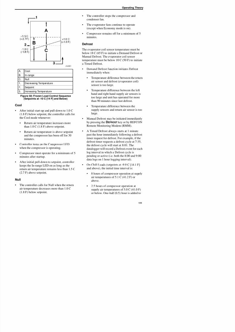
8/12/2019 Termo_King_Magnum_manual.pdf
http://slidepdf.com/reader/full/termokingmagnummanualpdf 111/194
Cool
• After initial start-up and pull-down to 1.0 C
(1.8 F) below setpoint, the controller calls for
the Cool mode whenever:
• Return air temperature increases more
than 1.0 C (1.8 F) above setpoint.
• Return air temperature is above setpoint
and the compressor has been off for 30
minutes.
• Controller turns on the Compressor LED
when the compressor is operating.
Defrost
The evaporator coil sensor temperature must be
below 18 C (65 F) to initiate a Demand Defrost or
Manual Defrost. The evaporator coil sensor
temperature must be below 10 C (50 F) to initiatea Timed Defrost.
• Demand Defrost function initiates Defrost
immediately when:
• Temperature difference between the return
air sensor and defrost (evaporator coil)
sensor is too large.• Temperature difference between the left
hand and right hand supply air sensors is
too large and unit has operated for more
than 90 minutes since last defrost.
• Temperature difference between the
supply sensors and return air sensor is too
large.
• Manual Defrost may be initiated immediately
by pressing the DEFROST key or by REFCON
Remote Monitoring Modem (RMM).
• A Timed Defrost always starts at 1 minute
past the hour immediately following a defrost
timer request for defrost. For example, if thedefrost timer requests a defrost cycle at 7:35,
the defrost cycle will start at 8:01. The
datalogger will record a Defrost event for each
A. Cool
B. In-range
C. Null
1. Decreasing Temperature
2. Setpoint
3. Increasing Temperature
Figure 58: Frozen Load Control Sequence(Setpoints at -10 C [14 F] and Below)
Operating Theory
the time interval each timed defrost
interval. Defrost synchronization creates
step intervals of 3, 4, 4, 5, 5, 6, 6 and 7
hours. Maximum time interval is 7 hours.
• On Frozen Loads, the initial time interval is 8
hours. Two (2) hours are added to the time
interval each timed defrost interval. Maximum
l t d ti i t l i 24 h
When the defrost mode is terminated:
• The Heat and Defrost LEDs turn off and the
heater contactor is de-energized. The
controller starts the compressor to pre-cool the
evaporator coil. The condenser fan starts if
required.
The controller pre-cools the evaporator coil to the
8/12/2019 Termo_King_Magnum_manual.pdf
http://slidepdf.com/reader/full/termokingmagnummanualpdf 112/194
accumulated time interval is 24 hours.
• Defrost timer resets if the unit is off more than
12 hours, setpoint is changed more than 5 C
(8.9 F) or PTI (pretrip) test occurs.
NOTE: If unit operating conditions do not allow the unit to enter a defrost cycle,
“Defrost Not Activated” appears on LCD
display when the DEFROST key is pressed.
When the Defrost mode is initiated:
• The controller stops the compressor,
condenser fan and evaporator fans.
• When the compressor stops, the controller
turns on the Defrost LED, Heat LED and
energizes the heater contactor, turning on the
electric heaters.
The controller terminates the Defrost
mode when:
• Evaporator temperature:
• Chill mode: Evaporator coil sensor
temperature reaches 30 C (86 F); or
exceeds 18 C (65 F) for 35 minutes/45
minutes if voltage is less than 440 volts.
• Frozen mode: Evaporator coil sensortemperature reaches 18 C (65 F); or
exceeds 8 C (46 F) for 35 minutes/45
minutes if voltage is less than 440 volts
p p
supply air temperature (or for 3 minutes
maximum) to minimize heat energy release into
the container. The controller then starts the
evaporator fans.
Compressor Digital ControlValve
The MP-3000a controller pulses the Compressor
Digital Control solenoid valve between open and
closed positions. This provides precise cooling
capacity control. No pump down function or
warm gas bypass control is used in conjunctionwith the Compressor Digital Control valve.
Figure 59: Compressor Digital Control SolenoidValve
The Compressor Digital Control valve is normally
closed. The normally closed position provides full
cooling capacity. When the controller energizes, it
opens the Compressor Digital Control valve.Refrigerant gas flows from the digital port of the
compressor back to the suction line. This
disengages the compressor 100 percent and
AXA0428
Operating Theory
(compressor pumping time) in the duty cycle
equals the cooling capacity percent required to
meet the current load demand.
Remember that the percent ON time defines the
time the compressor is engaged. The compressor
is engaged (pumping) when the Compressor
Digital Control valve is closed (OFF). Therefore,
a duty cycle of 100 percent means the compressor
prevents the gas from affecting the suction
pressure or cooling capacity of the evaporator
coil. However, the economizer suction gas adds
its heat and volume to the condenser side of the
refrigeration system, increasing the discharge
pressure.
Because the economizer system increases system
cooling capacity the vapor injection valve is

8/12/2019 Termo_King_Magnum_manual.pdf
http://slidepdf.com/reader/full/termokingmagnummanualpdf 113/194
a duty cycle of 100 percent means the compressor
is pumping 100 percent of the time and the
Compressor Digital Control valve is ON (open) 0
percent of the time. A 60 percent duty cycle
means the compressor is pumping 60 percent of
the time and the Compressor Digital Control valveis ON (open) 40 percent of the time.
Economizer System
An economizer heat exchange system replaces the
conventional heat exchanger. The economizer
system subcools the liquid refrigerant before it
reaches the evaporator expansion valve.Subcooling liquid refrigerant increases the
cooling efficiency and capacity of the evaporator.
Figure 60: Economizer Heat Exchanger
A vapor injection line tee is located in the liquid
line between the filter drier/in-line filter and theeconomizer heat exchanger. A vapor injection
valve controls refrigerant flow through the vapor
injection line to the economizer expansion valve.
cooling capacity, the vapor injection valve is
energized (open) continuously when the
compressor duty cycle (ON time) is 100 percent
(Full Cool). High compressor discharge
temperature may cause the vapor injection valve
to energize (open) but only while the CompressorDigital Control valve is not energized (closed).
Data Recording andDownloading Data
The MP-3000a data logger can record sensor
temperatures as well as loss of power, alarms,
sensor failure, setpoint change and unit shutdown
events. All data logs include the time and date;
setpoint temperature; supply, return, ambient,
USDA1, USDA2, USDA3 and cargo sensor
temperatures; and humidity sensor. All
temperature logs can be viewed from the
controller’s LCD message display.
Data logging intervals are selectable for 30
minutes, 1, 2 or 4 hours.
When a 1 hour logging interval is selected, the
data logger memory can store approximately 680
days of information. The logging of USDA
sensors is fixed at 1 hour intervals to comply with
USDA requirements. A logging test of USDA
sensors at 1 minute intervals is possible for 72
minutes. USDA data can not be downloaded
during the logging test and can only be viewed on
AXA0427
Operating Theory
laptop PC or a REFCON power line remote
monitoring system. LOGMAN data transfer rate
based on a 1 hour log interval is about 15 seconds
per month of event logs and about 70 seconds per
month of temperature logs. For example,
downloading 90 days of data logs would takeabout 95 seconds for event logs only and about
210 seconds for temperature logs only.
8/12/2019 Termo_King_Magnum_manual.pdf
http://slidepdf.com/reader/full/termokingmagnummanualpdf 114/194
Trip data from separate units is denoted by the
identification information entered into the
controller at the beginning of the trip via the
general purpose keypad. Identification data may
include the container ID number, location B.R.T.,contents, loading data, voyage no., ship, load port,
discharge port and comments. The container ID
number is stored in the Configuration submenu.
Controller Maintenance
Flash Loading ControllerSoftware
Controller software must be flash loaded when
software has been revised. To flash load softwarecomplete the following steps:
1 Turn the UNIT ON/OFF switch OFF
Controller Replacement
1. Turn the UNIT ON/OFF switch OFF.
2. Turn the unit 460/380V main circuit breaker
off.
3. Disconnect the unit power cord from the
l
8/12/2019 Termo_King_Magnum_manual.pdf
http://slidepdf.com/reader/full/termokingmagnummanualpdf 115/194
1. Turn the UNIT ON/OFF switch OFF.
2. Plug cable from a portable computer with
controller software into the data retrieval
connector on the control box.
3. Press and hold the 7 key and F1 key at thesame time. LCD display will show
[FLASHLOAD].
4. Press one of the special functions keys to
activate controller LCD display on battery
power; or turn the UNIT ON/OFF switch ON.
NOTE: Controller will start in Emergency mode and LCD display will show “EMERGENCY
MODE” if the communications cable is defective
or not connected to the download port. Secure
cable connection to proceed with flash loading
of software.
5. Start flash load program on portable computer.
6. Flash loading of new software is completewhen [FLASH LOADING] clears from the
LCD display.
7. The controller then checks the new software
and loads the new control program into
memory.
NOTE: If the flash load procedure is interrupted or fails on a MP3000a, the controller will stay in
the flash mode until correctly flash loaded.
If the flash load procedure is interrupted or fails
power supply.
4. Disconnect battery power connection from the
controller (top plug on the controller).
5. Disconnect the communication cables from
the controller and remote monitoring modem.
6. Remove the screws that secure the remote
monitoring modem to the controller.
7. Remove the screws that secure the controller
to the inside of the control box door.
8. Remove the controller from the door.
9. Install the replacement controller in the door
using the existing hardware.
10. Connect the keyboard cable to the controller.
11. Install the remote monitoring modem on theback of the controller.
12. Connect the communication cables to the
t it i d d t ll
WARNING: The unit will automatically
start and operate if 460/380V power is
present at the main relay board when the
controller is disconnected. Disconnect the supply power to the unit before replacing
the controller to prevent personal injury
from rotating machinery or dangerous
electrical shock from high voltage
controls.
Controller Maintenance
13. Recheck all connector plugs to ensure they are
fully seated.
14. Review the Configuration Menu instructions
in the operating section. Reset information as
required.
15. Review the Misc. Functions Menu
instructions in the operating section. Reset
i f ti i d
Automatic Configuration of SpareParts Controller
An automatic configuration feature detects the
unit options installed on a unit when a spare parts
controller is installed. When the controller is
powered up for the first time, the controller turns
the Auto Configuration feature on. After the
initial unit power up, the controller turns the Auto
8/12/2019 Termo_King_Magnum_manual.pdf
http://slidepdf.com/reader/full/termokingmagnummanualpdf 116/194
information as required.
NOTE: Be sure to enter the container ID before
releasing the unit for service. The container ID
is required to identify the data downloaded from
the controller datalogger via a laptop computer or a REFCON remote communications system.
NOTE: Several programmable features may
need to be set to completely configure the unit to
customer specifications. Adjust any additional
programmable settings to customer requirements
before releasing the unit for service.
NOTE: If a controller from another unit has
been installed, see “Automatic Configuration of
Spare Parts Controller” in this chapter to set
configuration correctly.
t a u t powe up, t e co t o e tu s t e uto
Configuration feature off.
The Auto Configuration feature detects the
following options and sets the correct value in
Configuration menu:
• Unit Type
• AFAM+
• Number of Supply Air Sensors (1 or 2):
Controller detects left hand and right supply
air sensors.
• Humidity sensors
• Horsepower and Condenser Fan (1/2 hp or
3/4 hp).
• Number of Evaporator Fans (2 or 3)
• Chart Recorder
• Fresh Air Exchange Recorder
• Discharge or Suction Pressure Sensors
Electrical Maintenance
Unit Protection Devices
Introduction
The unit has numerous protection devices. Theyare described in detail on the following pages.
Main Circuit Breaker
Control Circuit Fuses
Two control circuit fuses are located on the
controller. They protect the unit circuits and
components. No fuses are present on newercontrollers.
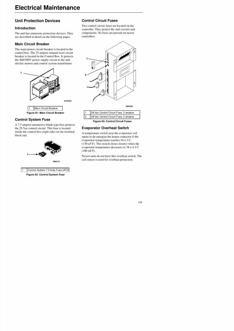
8/12/2019 Termo_King_Magnum_manual.pdf
http://slidepdf.com/reader/full/termokingmagnummanualpdf 117/194
Main Circuit Breaker
The main power circuit breaker is located in the
control box. The 25 ampere manual reset circuit
breaker is located in the Control Box. It protects
the 460/380V power supply circuit to the unitelectric motors and control system transformer.
Control System Fuse
A 7.5 ampere automotive blade type fuse protects
the 29 Vac control circuit. This fuse is located
inside the control box (right side) on the terminal
block rail.
Evaporator Overheat Switch
A temperature switch near the evaporator coil
opens to de-energize the heater contactor if the
evaporator temperature reaches 54 ± 3 C(130 ±5 F). The switch closes (resets) when the
evaporator temperature decreases to 38 ± 4.5 C
(100 ±8 F)
1. Main Circuit Breaker
Figure 61: Main Circuit Breaker
1
AXA0342
1. 28 Vac Control Circuit Fuse, 2 ampere2. 28 Vac Control Circuit Fuse, 2 ampere
Figure 63: Control Circuit Fuses
AMA308
1
2
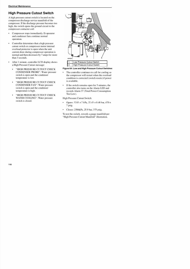
8/12/2019 Termo_King_Magnum_manual.pdf
http://slidepdf.com/reader/full/termokingmagnummanualpdf 118/194
Electrical Maintenance
High Pressure Cutout Manifold
1. Connect the manifold gauge to the compressor
discharge service valve with a heavy duty,
black jacketed thick wall #HCA 144 hose with
6024 kPa, 60.24 bar, 900 psig working
pressure rating.
2. Operate the unit in Cool by performing a
Capacity 100 percent test from the Manual
3. Raise the discharge pressure of the
compressor by blocking the condenser coil
airflow. Temporarily cover the compressor
compartment, control box and power cord
storage compartment with cardboard to reduce
condenser coil airflow. This should increasethe discharge pressure enough to cause the
switch to open. When the switch opens:
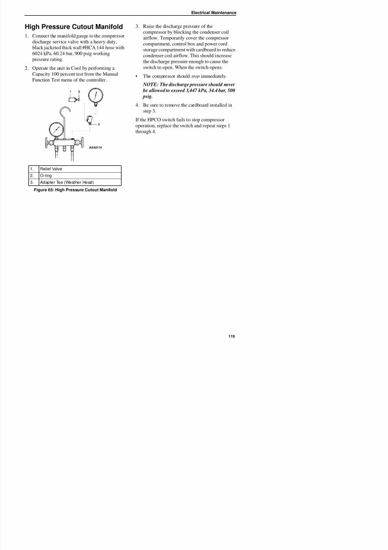
8/12/2019 Termo_King_Magnum_manual.pdf
http://slidepdf.com/reader/full/termokingmagnummanualpdf 119/194
Capacity 100 percent test from the Manual
Function Test menu of the controller.• The compressor should stop immediately.
NOTE: The discharge pressure should never
be allowed to exceed 3,447 kPa, 34.4 bar, 500
psig.
4. Be sure to remove the cardboard installed in
step 3.
If the HPCO switch fails to stop compressor
operation, replace the switch and repeat steps 1
through 4.
1. Relief Valve
2. O-ring
3. Adapter Tee (Weather Head)
Figure 65: High Pressure Cutout Manifold
AXA0174
Electrical Maintenance
High Pressure Cutout SwitchRemoval
Remove the high pressure cutout switch by
performing the following steps:
1. Isolate the compressor from the system.a. Front seat the discharge service valve by
turning the valve fully clockwise.
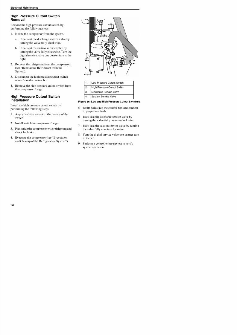
8/12/2019 Termo_King_Magnum_manual.pdf
http://slidepdf.com/reader/full/termokingmagnummanualpdf 120/194
b. Front seat the suction service valve by
turning the valve fully clockwise. Turn the
digital service valve one quarter turn to the
right.
2. Recover the refrigerant from the compressor.
(see “Recovering Refrigerant from the
System).
3. Disconnect the high pressure cutout switch
wires from the control box.
4. Remove the high pressure cutout switch from
the compressor flange.
High Pressure Cutout SwitchInstallation
Install the high pressure cutout switch by
performing the following steps:
1. Apply Locktite sealant to the threads of theswitch.
2. Install switch in compressor flange.
3. Pressurize the compressor with refrigerant and
check for leaks.
4. Evacuate the compressor (see “Evacuation
and Cleanup of the Refrigeration System”).
5. Route wires into the control box and connect
to proper terminals.
6. Back seat the discharge service valve by
turning the valve fully counter-clockwise.
7. Back seat the suction service valve by turning
the valve fully counter-clockwise.
8. Turn the digital service valve one quarter turn
to the left.
9. Perform a controller pretrip test to verify
system operation.
1. Low Pressure Cutout Switch
2. High Pressure Cutout Switch3. Discharge Service Valve
4. Suction Service Valve
Figure 66: Low and High Pressure Cutout Switches
12
34
Electrical Maintenance
Low Pressure Cutout Switch
A low pressure cutout switch is located on the
compressor suction line. If the suction pressure
becomes too low, the switch opens to stop the
compressor:
• Compressor stops immediately.
• Evaporator and condenser fans continue
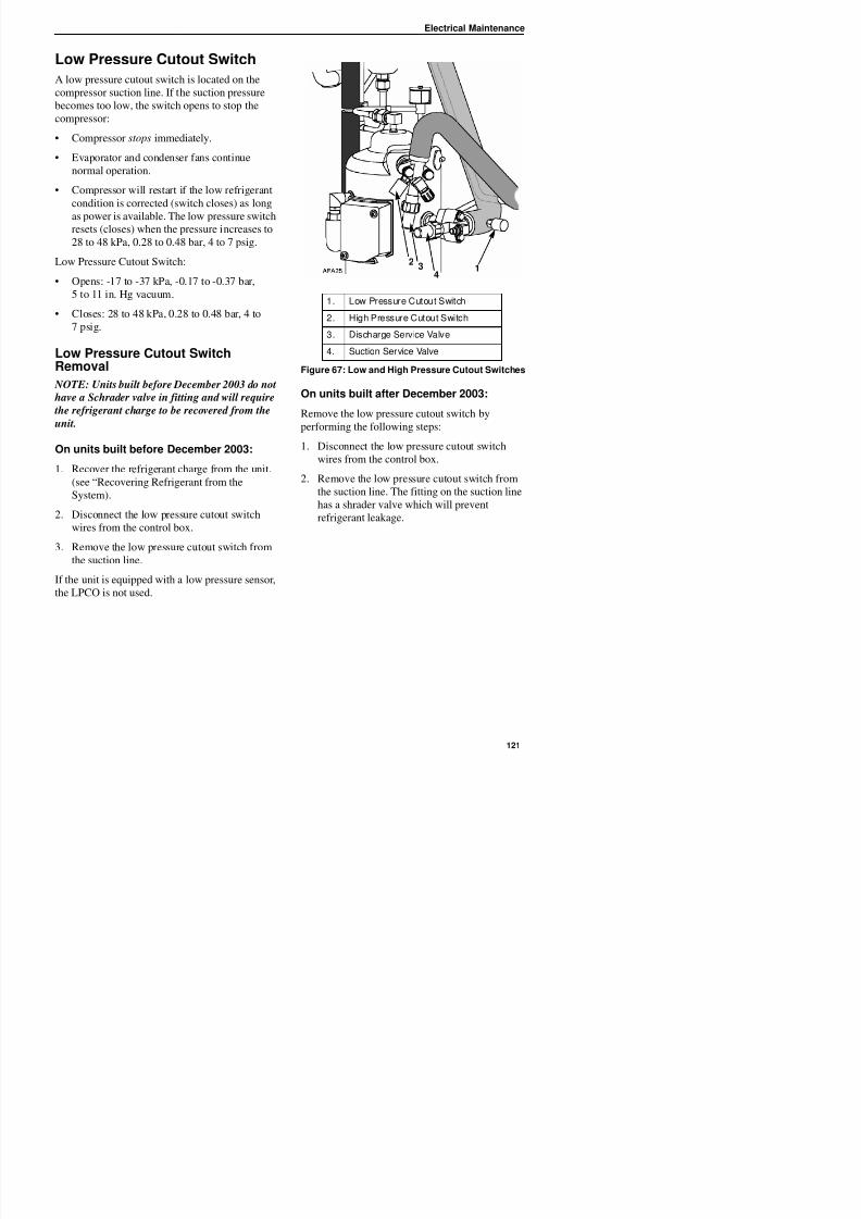
8/12/2019 Termo_King_Magnum_manual.pdf
http://slidepdf.com/reader/full/termokingmagnummanualpdf 121/194
normal operation.
• Compressor will restart if the low refrigerant
condition is corrected (switch closes) as long
as power is available. The low pressure switch
resets (closes) when the pressure increases to
28 to 48 kPa, 0.28 to 0.48 bar, 4 to 7 psig.
Low Pressure Cutout Switch:
• Opens: -17 to -37 kPa, -0.17 to -0.37 bar,
5 to 11 in. Hg vacuum.
• Closes: 28 to 48 kPa, 0.28 to 0.48 bar, 4 to
7 psig.
Low Pressure Cutout SwitchRemoval
NOTE: Units built before December 2003 do not
have a Schrader valve in fitting and will require
the refrigerant charge to be recovered from the
unit.
On units built before December 2003:
1. Recover the refrigerant charge from the unit.
(see “Recovering Refrigerant from the
System).
2. Disconnect the low pressure cutout switchwires from the control box.
3. Remove the low pressure cutout switch from
On units built after December 2003:
Remove the low pressure cutout switch byperforming the following steps:
1. Disconnect the low pressure cutout switch
wires from the control box.
2. Remove the low pressure cutout switch from
the suction line. The fitting on the suction line
has a shrader valve which will prevent
refrigerant leakage.
1. Low Pressure Cutout Switch
2. High Pressure Cutout Switch3. Discharge Service Valve
4. Suction Service Valve
Figure 67: Low and High Pressure Cutout Switches
12
34
Electrical Maintenance
Low Pressure Cutout SwitchInstallation
Install the low pressure cutout switch by
performing the following steps:
On units built before December 2003:
1. Install low pressure cutout switch in the
suction line.
Discharge and Low PressureSensors (Optional)
The unit can be configured discharge only, suction
only, or discharge and suction. The sensors are
located on the discharge or suction tubes near the
compressor. The controller will display the actual
discharge or suction system pressure. The display
will show a reading and a bar graph. If the unit is
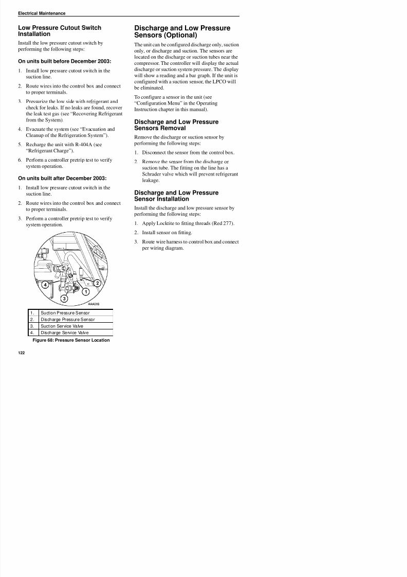
8/12/2019 Termo_King_Magnum_manual.pdf
http://slidepdf.com/reader/full/termokingmagnummanualpdf 122/194
2. Route wires into the control box and connect
to proper terminals.
3. Pressurize the low side with refrigerant and
check for leaks. If no leaks are found, recoverthe leak test gas (see “Recovering Refrigerant
from the System).
4. Evacuate the system (see “Evacuation and
Cleanup of the Refrigeration System”).
5. Recharge the unit with R-404A (see
“Refrigerant Charge”).
6. Perform a controller pretrip test to verify
system operation.
On units built after December 2003:
1. Install low pressure cutout switch in the
suction line.
2. Route wires into the control box and connect
to proper terminals.
3. Perform a controller pretrip test to verify
system operation.
configured with a suction sensor, the LPCO will
be eliminated.
To configure a sensor in the unit (see
“Configuration Menu” in the OperatingInstruction chapter in this manual).
Discharge and Low PressureSensors Removal
Remove the discharge or suction sensor by
performing the following steps:
1. Disconnect the sensor from the control box.
2. Remove the sensor from the discharge or
suction tube. The fitting on the line has a
Schrader valve which will prevent refrigerant
leakage.
Discharge and Low Pressure
Sensor InstallationInstall the discharge and low pressure sensor by
performing the following steps:
1. Apply Locktite to fitting threads (Red 277).
2. Install sensor on fitting.
3. Route wire harness to control box and connectper wiring diagram.
Electrical Maintenance
Condenser Fan and EvaporatorFan Rotation
NOTE: If both the condenser fan and
evaporator fans are rotating backwards,
diagnose the automatic phase selection system.
Check Condenser Fan Rotation
Check for proper condenser fan rotation by
Check Evaporator Fan Rotation
Visually inspect the evaporator fan blades for
proper rotation. Arrows located on the underside
of the fan deck indicate the correct direction of
rotation.
Check both high and low speed evaporator fan
rotation by performing Evaporator High and
Evaporator Low tests from the Manual Function
8/12/2019 Termo_King_Magnum_manual.pdf
http://slidepdf.com/reader/full/termokingmagnummanualpdf 123/194
p p y
placing a small cloth or sheet of paper against the
condenser fan grille on the front of the unit.
Proper rotation will blow the cloth or paper away
from the grille. Improper rotation will hold the
cloth or paper against the grille.
If the condenser fan is rotating backwards, see the
unit wiring diagram to correct fan motor wiring at
the fan motor junction box or condenser fan
contactor. To correct improper fan rotation,
reverse any two fan power cord leads at the
condenser fan contactor (disconnect power supply
before reversing leads). Do not move the CH
ground wire.
Test menu.
If an evaporator fans rotate backwards on one or
both speeds, see the unit wiring diagram to correct
motor wiring at the fan motor junction box orevaporator fan contactor (disconnect power
supply before reversing leads). ( Do not move the
ground wire which is labeled CH.)
NOTE: Evaporator fan motor wires EF1, EF2
and EF3 are used on low speed fan operation.
Wires EF11, EF12 and EF13 are used on high
speed fan operation.
Electrical Maintenance
Reversing Power Phase onMAGNUM Units
Use the incoming power cable leads to reverse the
power phase. This is recommended on
MAGNUM units because the Jumper J18 does not
reverse power to the scroll compressor. This
protects against the possibility that the compressor
will be out of phase with the condenser and
t f h th it i l d i t
Electric Heaters Malfunction
Six electric heater elements are located
underneath the evaporator coil. If a heater element
is suspected of malfunctioning, check the
resistance of each individual heater element by
performing the following procedure:
1. Turn unit power supply off.
2 Remove unit power plug from power supply
8/12/2019 Termo_King_Magnum_manual.pdf
http://slidepdf.com/reader/full/termokingmagnummanualpdf 124/194
evaporator fans when the unit is plugged into a
new power supply.
To reverse the Power Phase Complete complete
the following steps:
1. Turn the unit 460/380V main circuit breaker
off.
2. Disconnect unit power cord from power
supply.
3. Relocate the position of the white and black
incoming power cord leads at the 460/380V
main circuit breaker.
4. Connect unit power cord to proper power
supply.
5. Start the unit again by turning the unit
460/380V main circuit breaker on and the Unit
On/Off switch On.
6 Check condenser airflow again to confirm
2. Remove unit power plug from power supply
receptacle.
3. Open the control box door.
4. Test the insulation of each individual heaterelement.
a. Test all 3 legs of the heater circuit to a
good ground connection. Connect a
calibrated 500 Vdc insulation tester
between each outgoing heater contactor
terminal and ground.
b. If the resistance between any contactor
terminal and ground is below 0.8 meg
ohms, isolate and check the resistance of
each individual heater element.
5. Check the resistance of each individual heater
element.
a. Disconnect and isolate each heater fromthe circuit in the control box.
b. Check resistance of each heater with an
insulation tester between each heater and
ground. If the resistance between each
heater and ground is below 0.8 meg ohms,
the heater element is defective. On a
loaded container, remove the defectiveheater from service by disconnecting at the
control box. If the container is empty,
th t f th
WARNING: The unit will automatically
start and operate if 460/380V power is present at the main relay board when the
controller is disconnected. To prevent
personal injury from rotating machinery
or dangerous electrical shock from high
voltage controls, disconnect the supply
power to the unit before preparing the unit
for manual emergency mode operation.
Electrical Maintenance
Compressor DischargeTemperature Sensor Replacement
The compressor discharge temperature sensor is
mounted externally on the compressor head. To
remove:
1. Shut off power to system.
2. Disconnect the compressor discharge sensor
wires from J-15--pins 9 & 10 located in the
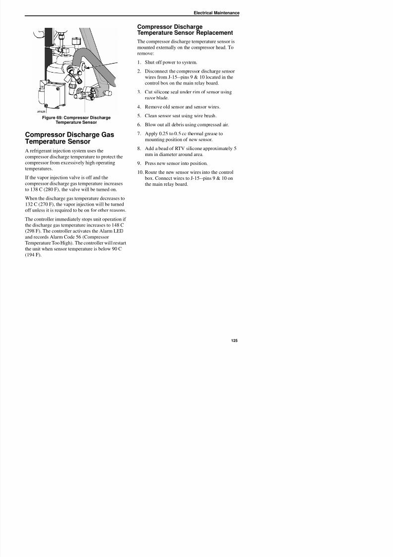
8/12/2019 Termo_King_Magnum_manual.pdf
http://slidepdf.com/reader/full/termokingmagnummanualpdf 125/194
Figure 69: Compressor DischargeTemperature Sensor
Compressor Discharge GasTemperature Sensor
A refrigerant injection system uses the
compressor discharge temperature to protect the
compressor from excessively high operating
temperatures.
If the vapor injection valve is off and the
compressor discharge gas temperature increases
to 138 C (280 F), the valve will be turned on.When the discharge gas temperature decreases to
132 C (270 F), the vapor injection will be turned
off unless it is required to be on for other reasons.
The controller immediately stops unit operation if
the discharge gas temperature increases to 148 C
(298 F). The controller activates the Alarm LED
and records Alarm Code 56 (CompressorTemperature Too High). The controller will restart
the unit when sensor temperature is below 90 C
wires from J 15 pins 9 & 10 located in the
control box on the main relay board.
3. Cut silicone seal under rim of sensor using
razor blade.
4. Remove old sensor and sensor wires.
5. Clean sensor seat using wire brush.
6. Blow out all debris using compressed air.
7. Apply 0.25 to 0.5 cc thermal grease to
mounting position of new sensor.
8. Add a bead of RTV silicone approximately 5mm in diameter around area.
9. Press new sensor into position.
10. Route the new sensor wires into the control
box. Connect wires to J-15--pins 9 & 10 on
the main relay board.
Electrical Maintenance
Installing Temperature Sensors
All sensors should be properly installed as
follows:
• Supply air sensors must be inserted to the
bottom of the sensor tube and completelysealed by the grommet connection.
• Left hand supply sensor installs in the sensor
tube on the left side of the RH sensor tube.
1
1
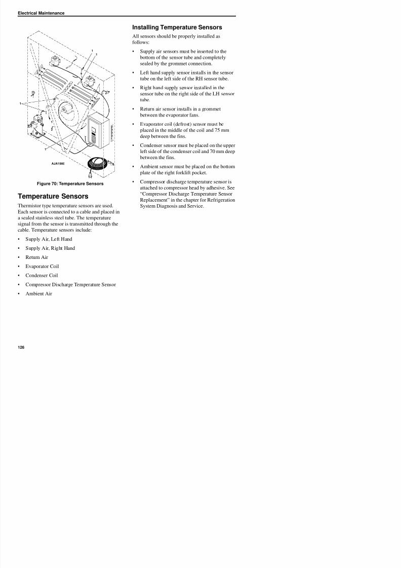
8/12/2019 Termo_King_Magnum_manual.pdf
http://slidepdf.com/reader/full/termokingmagnummanualpdf 126/194
Figure 70: Temperature Sensors
Temperature SensorsThermistor type temperature sensors are used.
Each sensor is connected to a cable and placed in
a sealed stainless steel tube. The temperature
signal from the sensor is transmitted through the
cable. Temperature sensors include:
• Supply Air, Left Hand
• Supply Air, Right Hand
• Return Air
• Right hand supply sensor installed in the
sensor tube on the right side of the LH sensor
tube.
• Return air sensor installs in a grommet
between the evaporator fans.
• Evaporator coil (defrost) sensor must be
placed in the middle of the coil and 75 mm
deep between the fins.
• Condenser sensor must be placed on the upper
left side of the condenser coil and 70 mm deepbetween the fins.
• Ambient sensor must be placed on the bottom
plate of the right forklift pocket.
• Compressor discharge temperature sensor is
attached to compressor head by adhesive. See
“Compressor Discharge Temperature SensorReplacement” in the chapter for Refrigeration
System Diagnosis and Service.
1
1
1
AJA1980
Electrical Maintenance
Testing the Sensors
The controller constantly monitors the left hand
and right hand supply sensors, return sensor and
defrost (evaporator coil) sensor to determine when
to initiate a demand defrost. If a demand defrost is
requested and defrost has occurred within the last
90 minutes, the controller initiates a probe test to
check for a defective sensor.
D i P b t t th LCD di l h
AXA0172
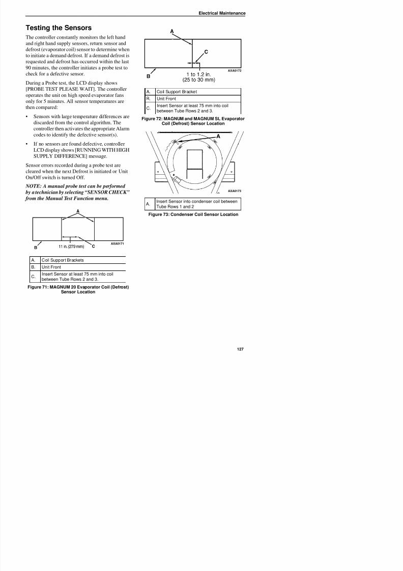
8/12/2019 Termo_King_Magnum_manual.pdf
http://slidepdf.com/reader/full/termokingmagnummanualpdf 127/194
During a Probe test, the LCD display shows
[PROBE TEST PLEASE WAIT]. The controller
operates the unit on high speed evaporator fans
only for 5 minutes. All sensor temperatures are
then compared:
• Sensors with large temperature differences are
discarded from the control algorithm. The
controller then activates the appropriate Alarm
codes to identify the defective sensor(s).
• If no sensors are found defective, controller
LCD display shows [RUNNING WITH HIGHSUPPLY DIFFERENCE] message.
Sensor errors recorded during a probe test are
cleared when the next Defrost is initiated or Unit
On/Off switch is turned Off.
NOTE: A manual probe test can be performed
by a technician by selecting “SENSOR CHECK”
from the Manual Test Function menu.
A C il S t B k t
AXA0171
A. Coil Support Bracket
B. Unit Front
C. Insert Sensor at least 75 mm into coilbetween Tube Rows 2 and 3.
Figure 72: MAGNUM and MAGNUM SL EvaporatorCoil (Defrost) Sensor Location
A.Insert Sensor into condenser coil betweenTube Rows 1 and 2
Figure 73: Condenser Coil Sensor Location
AXA0173
Electrical Maintenance
Resistance Values for TemperatureSensors
Sensors are permanently calibrated and can be
checked using an ohmmeter. Ohm readings should
agree with the data shown in the following Sensor
resistance tables.
Resistance Values for Supply, Return, EvaporatorCoil, Condenser Coil and Ambient Air Sensors
Temp.F
Temp.C
OhmsTemp.
FTemp.
COhms
-40 -40 42,618 53.6 12 3,360
-31 -35 32,198 57.2 14 3,094-22 -30 24,532 60.8 16 2,852
-13 -25 18,850 64.4 18 2,632
-4 -20 14,618 68 20 2,431
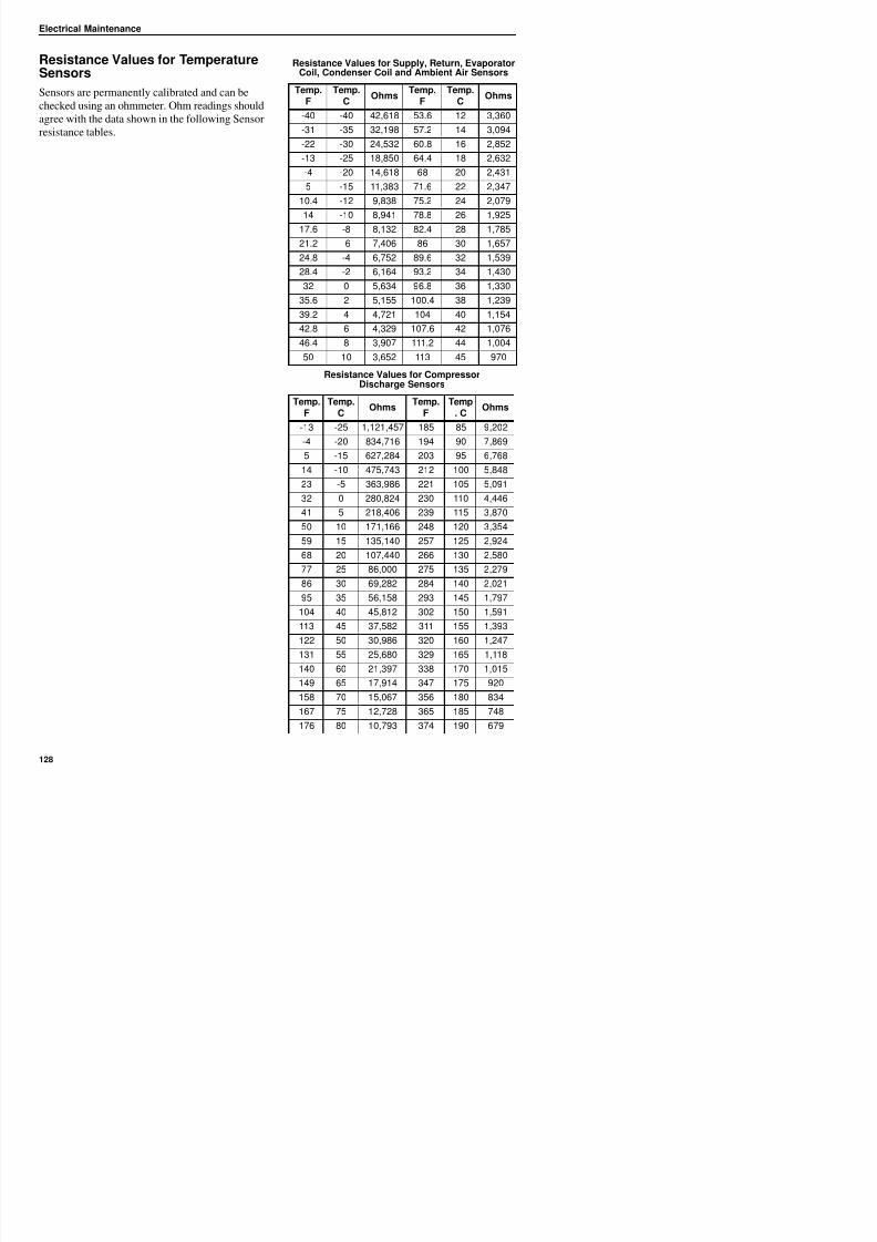
8/12/2019 Termo_King_Magnum_manual.pdf
http://slidepdf.com/reader/full/termokingmagnummanualpdf 128/194
5 -15 11,383 71.6 22 2,347
10.4 -12 9,838 75.2 24 2,079
14 -10 8,941 78.8 26 1,925
17.6 -8 8,132 82.4 28 1,78521.2 -6 7,406 86 30 1,657
24.8 -4 6,752 89.6 32 1,539
28.4 -2 6,164 93.2 34 1,430
32 0 5,634 96.8 36 1,330
35.6 2 5,155 100.4 38 1,239
39.2 4 4,721 104 40 1,154
42.8 6 4,329 107.6 42 1,07646.4 8 3,907 111.2 44 1,004
50 10 3,652 113 45 970
Resistance Values for CompressorDischarge Sensors
Temp.F
Temp.C
OhmsTemp.
FTemp
. COhms
-13 -25 1,121,457 185 85 9,202-4 -20 834,716 194 90 7,869
5 -15 627,284 203 95 6,768
14 -10 475,743 212 100 5,848
23 -5 363,986 221 105 5,091
32 0 280,824 230 110 4,446
41 5 218,406 239 115 3,870
50 10 171,166 248 120 3,35459 15 135,140 257 125 2,924
68 20 107,440 266 130 2,580
Refrigeration Maintenance
Introduction
The following procedures involve servicing the
refrigeration system. Some of these service
procedures are regulated by Federal, and in somecases, by State and Local laws.
NOTE: All regulated refrigeration service
procedures must be performed by an EPA
ifi d h i i i d i
Use the Correct RefrigerantRecovery Equipment
Use only refrigerant recovery equipment
approved for and dedicated to R-404A recovery.
Detecting Leaks
Leaks can be detected with the use of soap
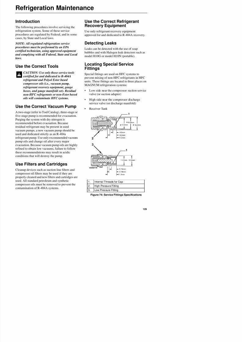
8/12/2019 Termo_King_Magnum_manual.pdf
http://slidepdf.com/reader/full/termokingmagnummanualpdf 129/194
certified technician, using approved equipment
and complying with all Federal, State and Local
laws.
Use the Correct Tools
Use the Correct Vacuum Pump
A two-stage (refer to Tool Catalog), three-stage or
five-stage pump is recommended for evacuation.
Purging the system with dry nitrogen is
recommended before evacuation. Because
residual refrigerant may be present in used
vacuum pumps, a new vacuum pump should be
used and dedicated strictly as an R-404a
refrigerant pump. Use only recommended vacuum
pump oils and change oil after every major
evacuation. Because vacuum pump oils are highlyrefined to obtain low vacuums, failure to follow
these recommendations may result in acidic
di i h ill d h
w p
bubbles and with Halogen leak detectors such as
model H10G or model H10N (portable).
Locating Special ServiceFittings
Special fittings are used on HFC systems to
prevent mixing of non-HFC refrigerants in HFC
units. These fittings are located in three places on
MAGNUM refrigeration systems:
• Low side near the compressor suction servicevalve (or suction adapter)
• High side near the compressor discharge
service valve (or discharge manifold)
• Receiver Tank
CAUTION: Use only those service tools
certified for and dedicated to R-404A
refrigerant and Polyol Ester based
compressor oils (i.e., vacuum pump,
refrigerant recovery equipment, gauge
hoses, and gauge manifold set). Residual non-HFC refrigerants or non-Ester based
oils will contaminate HFC systems.

8/12/2019 Termo_King_Magnum_manual.pdf
http://slidepdf.com/reader/full/termokingmagnummanualpdf 130/194
Refrigeration Maintenance
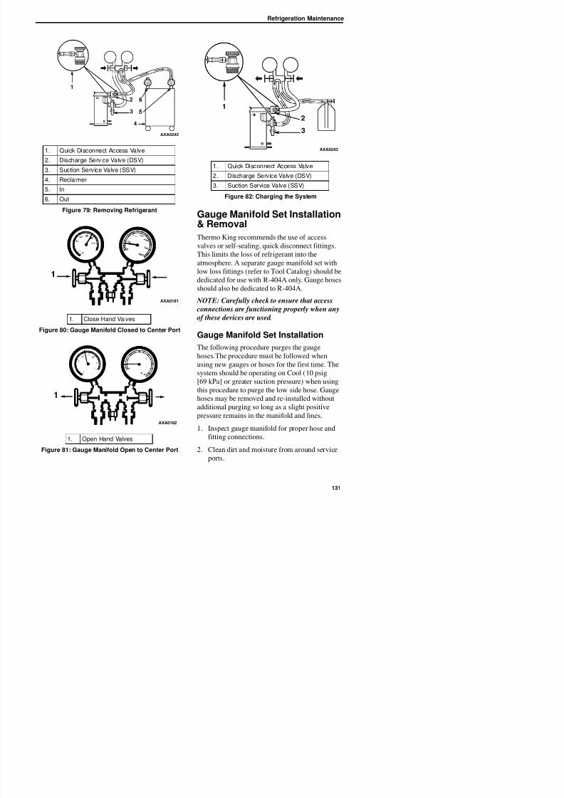
8/12/2019 Termo_King_Magnum_manual.pdf
http://slidepdf.com/reader/full/termokingmagnummanualpdf 131/194
Gauge Manifold Set Installation& Removal
Thermo King recommends the use of access
valves or self-sealing, quick disconnect fittings.
This limits the loss of refrigerant into the
atmosphere. A separate gauge manifold set with
low loss fittings (refer to Tool Catalog) should bededicated for use with R-404A only. Gauge hoses
should also be dedicated to R-404A.
NOTE: Carefully check to ensure that access
connections are functioning properly when any
of these devices are used.
Gauge Manifold Set InstallationThe following procedure purges the gauge
hoses.The procedure must be followed when
i h f h fi i h
1. Quick Disconnect Access Valve
2. Discharge Service Valve (DSV)
3. Suction Service Valve (SSV)
4. Reclaimer
5. In
6. Out
Figure 79: Removing Refrigerant
1. Close Hand Valves
Figure 80: Gauge Manifold Closed to Center Port
AXA0242
AXA0181
1. Quick Disconnect Access Valve
2. Discharge Service Valve (DSV)
3. Suction Service Valve (SSV)
Figure 82: Charging the System
AXA0243
Refrigeration Maintenance
3. Remove small service port caps from suction
and discharge service fittings. Save and reuse
the caps and sealing washers or gaskets.
4. Rotate both hose coupler hand wheels
counterclockwise to back the stem out of the
high and low hose fittings. Attach low hose(compound gauge) to the suction line valve
port.
5. Open the suction service manifold hand valve2
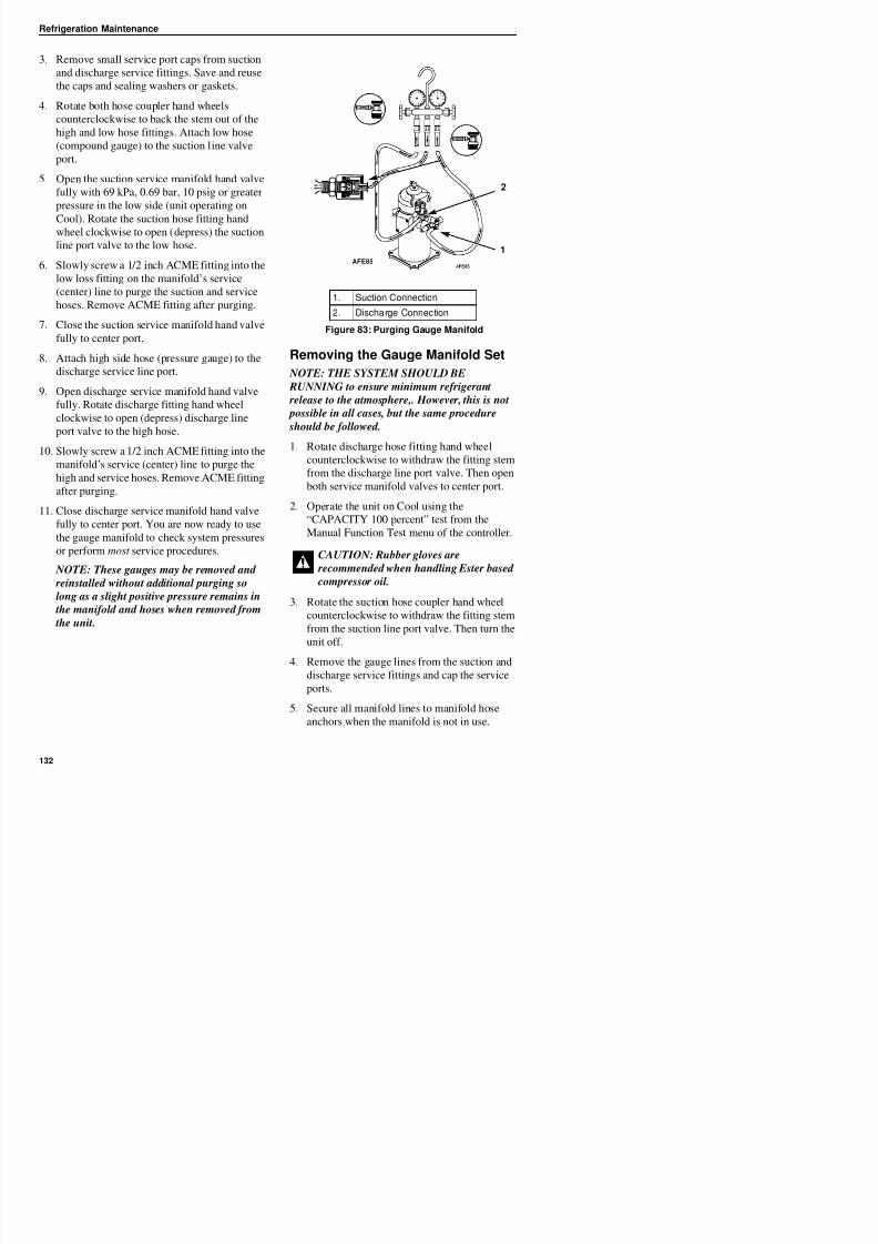
8/12/2019 Termo_King_Magnum_manual.pdf
http://slidepdf.com/reader/full/termokingmagnummanualpdf 132/194
fully with 69 kPa, 0.69 bar, 10 psig or greater
pressure in the low side (unit operating on
Cool). Rotate the suction hose fitting hand
wheel clockwise to open (depress) the suctionline port valve to the low hose.
6. Slowly screw a 1/2 inch ACME fitting into the
low loss fitting on the manifold’s service
(center) line to purge the suction and service
hoses. Remove ACME fitting after purging.
7. Close the suction service manifold hand valvefully to center port.
8. Attach high side hose (pressure gauge) to the
discharge service line port.
9. Open discharge service manifold hand valve
fully. Rotate discharge fitting hand wheel
clockwise to open (depress) discharge line
port valve to the high hose.
10. Slowly screw a 1/2 inch ACME fitting into the
manifold’s service (center) line to purge the
high and service hoses. Remove ACME fitting
after purging.
11. Close discharge service manifold hand valve
fully to center port. You are now ready to usethe gauge manifold to check system pressures
or perform most service procedures.
Removing the Gauge Manifold Set
NOTE: THE SYSTEM SHOULD BE
RUNNING to ensure minimum refrigerant
release to the atmosphere,. However, this is not
possible in all cases, but the same procedure
should be followed.
1. Rotate discharge hose fitting hand wheel
counterclockwise to withdraw the fitting stem
from the discharge line port valve. Then open
both service manifold valves to center port.
2. Operate the unit on Cool using the
“CAPACITY 100 percent” test from the
Manual Function Test menu of the controller.
1. Suction Connection
2. Discharge Connection
Figure 83: Purging Gauge Manifold
CAUTION: Rubber gloves are
d d h h dl b d
1
2
AFE85
Refrigeration Maintenance
Checking Refrigerant Charge
The refrigerant charge should be checked during
pretrip and routine maintenance inspections. A
low charge of refrigerant will cause the container
temperature to rise due to the lack of liquid
refrigerant at the expansion valve even though theunit is operating in a cooling mode. All
MAGNUM units are charged with 4.0 kg (8.0 lbs)
R-404A refrigerant at the factory. The refrigerant
charge can be checked by inspecting the receiver
Receiver Tank Sight Glass
The receiver tank contains a sight glass which has
three small balls that indicate the level of
refrigerant in the tank for checking the refrigerant
charge. A moisture indicator in the sight glass
changes color to indicate the level of moisture inthe system. Check the color of the indicator
against the color decal in the sight glass. The dry
eye in the sight glass is light green when the
system is dry and yellow when the system is wet
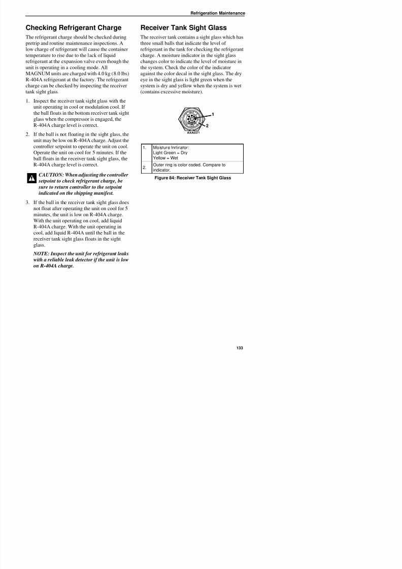
8/12/2019 Termo_King_Magnum_manual.pdf
http://slidepdf.com/reader/full/termokingmagnummanualpdf 133/194
charge can be checked by inspecting the receiver
tank sight glass.
1. Inspect the receiver tank sight glass with the
unit operating in cool or modulation cool. Ifthe ball floats in the bottom receiver tank sight
glass when the compressor is engaged, the
R-404A charge level is correct.
2. If the ball is not floating in the sight glass, the
unit may be low on R-404A charge. Adjust the
controller setpoint to operate the unit on cool.
Operate the unit on cool for 5 minutes. If theball floats in the receiver tank sight glass, the
R-404A charge level is correct.
3. If the ball in the receiver tank sight glass does
not float after operating the unit on cool for 5
minutes, the unit is low on R-404A charge.
With the unit operating on cool, add liquid
R-404A charge. With the unit operating in
cool, add liquid R-404A until the ball in the
receiver tank sight glass floats in the sightglass.
NOTE: Inspect the unit for refrigerant leaks
i h li bl l k d if h i i l
system is dry and yellow when the system is wet
(contains excessive moisture).
CAUTION: When adjusting the controller
setpoint to check refrigerant charge, be
sure to return controller to the setpoint
indicated on the shipping manifest.
1. Moisture Indicator:Light Green = DryYellow = Wet
2.Outer ring is color coded. Compare toindicator.
Figure 84: Receiver Tank Sight Glass
AXA0371
Refrigeration Maintenance
Leak Testing the RefrigerationSystem
Use a reliable Halogen leak detector such as
model H10G (refer to Tool Catalog), to leak test
the refrigeration system. Inspect carefully for
signs of compressor oil leakage which is the first
sign of a leak in the refrigeration system.
NOTE: Due to environmental concerns and
personal safety, the use of a Halide torch is no
NOTE: If system leakage is indicated, loosen
supply line hose fittings to release pressure.
Repair leakage condition.
12. If system repair is necessary, recheck system
after repairs are completed.
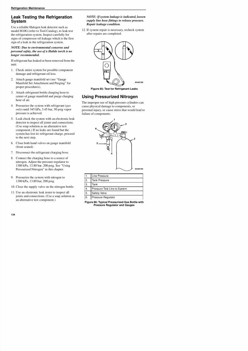
8/12/2019 Termo_King_Magnum_manual.pdf
http://slidepdf.com/reader/full/termokingmagnummanualpdf 134/194
longer recommended.
If refrigerant has leaked or been removed from the
unit:1. Check entire system for possible component
damage and refrigerant oil loss.
2. Attach gauge manifold set (see “Gauge
Manifold Set Attachment and Purging” for
proper procedures).
3. Attach refrigerant bottle charging hose tocenter of gauge manifold and purge charging
hose of air.
4. Pressurize the system with refrigerant (gas
only) until 345 kPa, 3.45 bar, 50 psig vapor
pressure is achieved.
5. Leak check the system with an electronic leak
detector to inspect all joints and connections.
(Use soap solution as an alternative test
component.) If no leaks are found but the
system has lost its refrigerant charge, proceed
to the next step.
6. Close both hand valves on gauge manifold
(front seated).
7. Disconnect the refrigerant charging hose.
8. Connect the charging hose to a source of
Figure 85: Test for Refrigerant Leaks
Using Pressurized Nitrogen
The improper use of high pressure cylinders can
cause physical damage to components, or
personal injury, or cause stress that would lead to
failure of components.
AXA0186
Refrigeration Maintenance
Safety Precautions
Observe the proper handling of cylinders:
• Always keep protective cap on cylinder when
not in use.
• Secure cylinder in proper storage area orfastened to cart.
• Do not expose to excessive heat or direct sun
light.
Purge High Side to Low Side
1. Attach gauge manifold set (see “Gauge
Manifold Set Attachment and Purging” for
proper procedure for connecting to
compressor).
2. Close both hand valves on the gauge manifold
(front seated).
3. Connect charging hose to a source of nitrogen.
Adjust pressure regulator to the proper
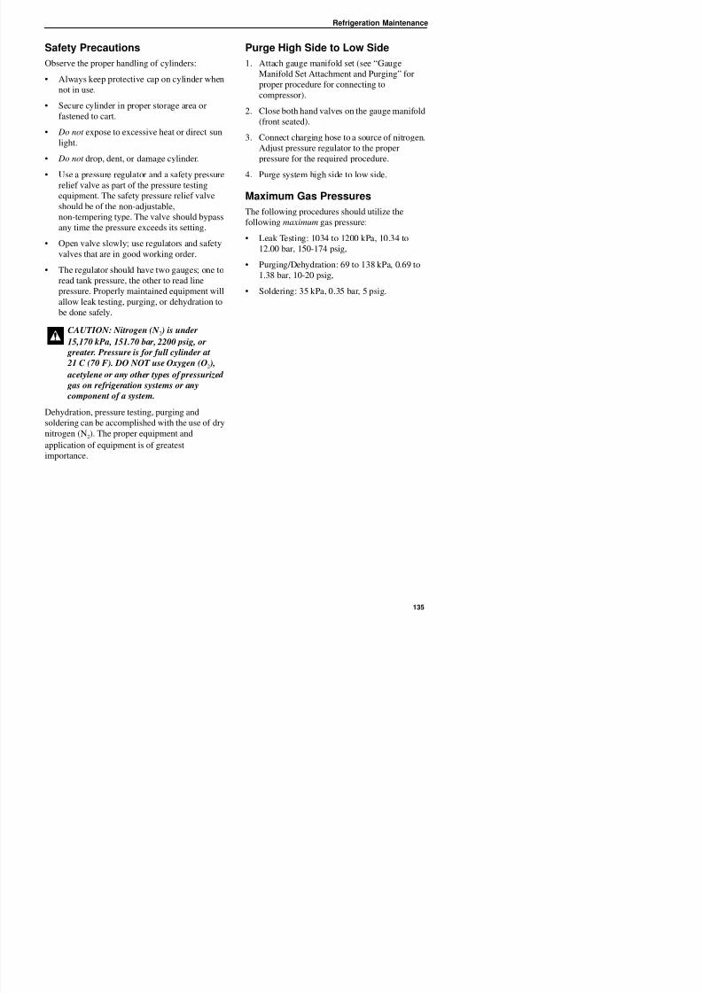
8/12/2019 Termo_King_Magnum_manual.pdf
http://slidepdf.com/reader/full/termokingmagnummanualpdf 135/194
• Do not drop, dent, or damage cylinder.
• Use a pressure regulator and a safety pressure
relief valve as part of the pressure testingequipment. The safety pressure relief valve
should be of the non-adjustable,
non-tempering type. The valve should bypass
any time the pressure exceeds its setting.
• Open valve slowly; use regulators and safety
valves that are in good working order.
• The regulator should have two gauges; one to
read tank pressure, the other to read line
pressure. Properly maintained equipment will
allow leak testing, purging, or dehydration to
be done safely.
Dehydration, pressure testing, purging and
soldering can be accomplished with the use of drynitrogen (N2). The proper equipment and
application of equipment is of greatest
j p g p p
pressure for the required procedure.
4. Purge system high side to low side.
Maximum Gas Pressures
The following procedures should utilize the
following maximum gas pressure:
• Leak Testing: 1034 to 1200 kPa, 10.34 to
12.00 bar, 150-174 psig,
• Purging/Dehydration: 69 to 138 kPa, 0.69 to1.38 bar, 10-20 psig,
• Soldering: 35 kPa, 0.35 bar, 5 psig.
CAUTION: Nitrogen (N 2 ) is under
15,170 kPa, 151.70 bar, 2200 psig, or greater. Pressure is for full cylinder at
21 C (70 F). DO NOT use Oxygen (O2 ),
acetylene or any other types of pressurized
gas on refrigeration systems or any
component of a system.
Refrigeration Maintenance
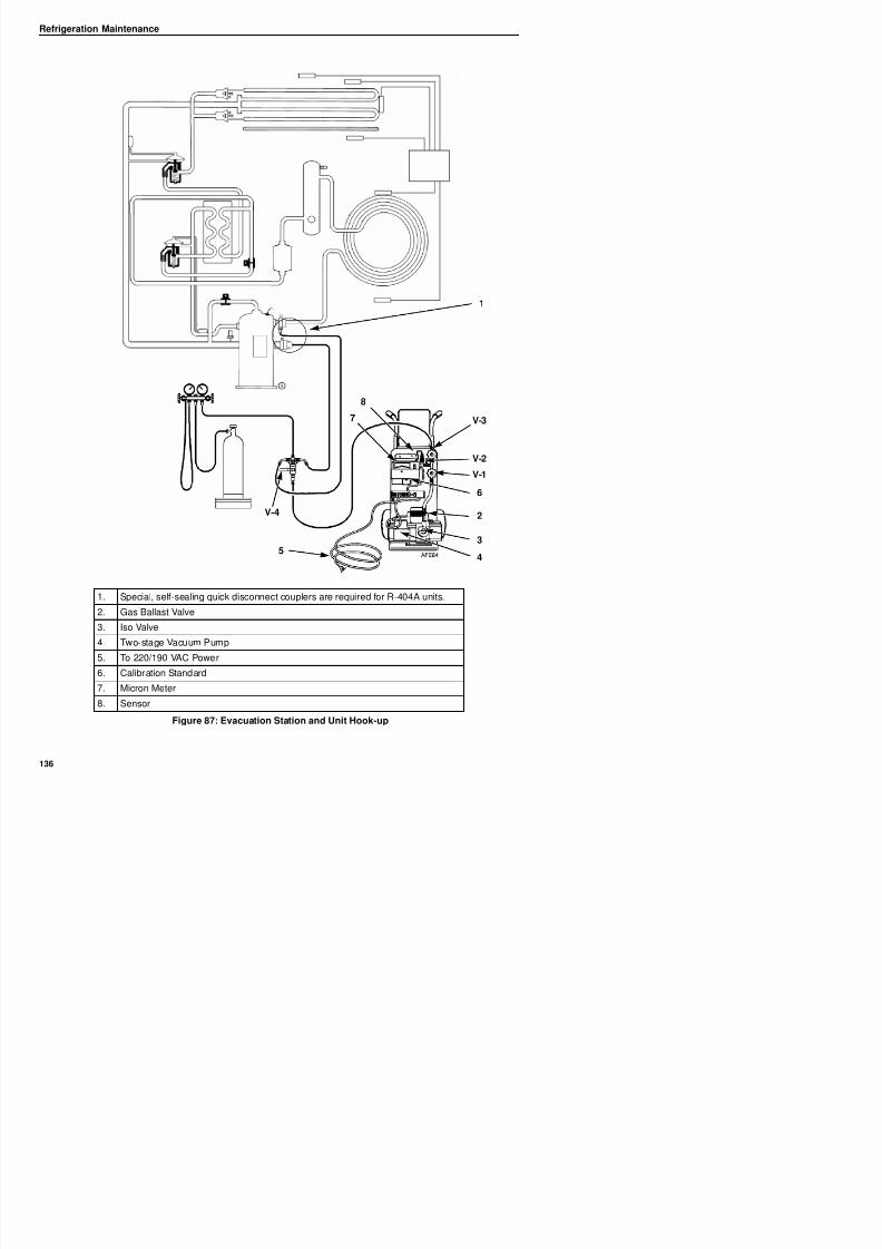
8/12/2019 Termo_King_Magnum_manual.pdf
http://slidepdf.com/reader/full/termokingmagnummanualpdf 136/194
1
2
3
45
6
7
8
V-1
V-2
V-3
V-4
Refrigeration Maintenance
Recovering Refrigerant fromthe System
When removing any refrigerant from a Thermo
King refrigeration system, use a recovery process
that prevents or absolutely minimizes the
refrigerant escaping to the atmosphere. Typical
Evacuation and Cleanup of theRefrigeration System
A thorough clean up is required whenever
contaminants have entered the system. This will
prevent damage to the compressor.
The purpose of evacuation is to remove moisture
and air from the refrigeration system after a
system has been opened to the atmosphere.
Evacuation must occur before recharging a system
i h f i Th i f h h
CAUTION: Use only refrigerant recovery
equipment approved for and dedicated to
R-404A recovery.
8/12/2019 Termo_King_Magnum_manual.pdf
http://slidepdf.com/reader/full/termokingmagnummanualpdf 137/194
service procedures that require removal of
refrigerant from the unit includes the following:
• Reduce the refrigerant pressure to a safeworking level when maintenance must be
performed on high-pressure side components.
• Empty the unit of refrigerant when an
unknown amount of charge is in the system
and a proper charge is required.
• Empty the unit of contaminated refrigerantwhen the system has become contaminated.
NOTE: Always refer to specific recovery
equipment Operator and Service Manuals.
Perform the following steps to recover vapor from
the system.
1. Turn unit off.
2. Install a gauge manifold set on the unit.
3. Attach the service line to the recovery
machine and properly purge the lines.
4. Set the recovery machine for vapor recovery.
5. Mid-seat the discharge service valve.
6. Turn on the recovery machine.
7. Open (back seat) both gauge manifold and
with new refrigerant. The importance of thorough
evacuation and system preparation cannot be over
emphasized. Even infinitesimal quantities of air or
moisture in a system can cause severe problems.
The presence of moisture, oxygen, and heat can
create many forms of damage. They can create
corrosion, sludge, copper plating, oil breakdown,
carbon formation, and eventual compressor
failure.
Things that will contaminate a system are (inorder of importance):
Air: With oxygen as a contaminant: Oxygen in the
air reacts with the oil. The oil begins to break
down and can eventually lead to carbonization in
the compressor and acid buildup. The longer this
breakdown process goes on, the darker the
compressor oil becomes until finally the color isblack indicating major system contamination.
Moisture: Moisture in a system will cause metal
corrosion and metal plating. It can freeze in the
expansion valve and cause intermittent
operational problems. It reacts in the oil to begin
acid buildup.
Dirt, Dust, Metal Particles, other ForeignMaterials: Particles of any kind left to float
through the system will cause severe damage to
ll l t l it D t l t
Refrigeration Maintenance
Unit Preparation and Hookup
1. Recover all refrigerants from the unit and
reduce the unit pressure to the proper level
(US Federal Law requires a -17 to -34 kPa,
0 17 to 0 34 bar 5 to 10 in vacuum that is
4. Connect the evacuation station and refrigerant
tank with gauge manifold (optional) to the
unit as indicated in figure Figure 87 on page
136. Connect evacuation hoses to the
compressor suction and discharge service
fittings.
5. Open Evacuation Station valves (V1, V3, and
V4). It is only necessary to open valve V2
when a reading on the micron meter is desired.
This is especially true when starting to
CAUTION: Do not attempt to evacuate a
unit until it is certain that the unit is leak
free. A unit with less than a full charge of
refrigerant should be thoroughly leak
tested. Any leaks found must be repaired.
8/12/2019 Termo_King_Magnum_manual.pdf
http://slidepdf.com/reader/full/termokingmagnummanualpdf 138/194
-0.17 to -0.34 bar, 5 to 10 in. vacuum that is
dependent upon the recovery equipment
used).
2. Break vacuum with refrigerant and equalize
system pressure to 0 kPa, 0 bar, 0 psig.
Replace the liquid line filter drier if necessary.
NOTE: Replace the one-piece filter drier
when major system contamination requires
evacuation and cleanup of the refrigeration
system.3. Confirm that the evacuation station functions
properly. Determine “Blank Off” pressure.
The “Blank Off” pressure of the vacuum
pump is the deepest vacuum that the vacuum
pump can attain when isolated from the rest of
the system. The operator can be confident that
the pump and oil are in good condition, if avacuum pump (isolated from a system) is
started and the micron meter responds quickly
by going to a deep vacuum. If the vacuum
pump fails to reach a deep vacuum within 5
minutes, the operator should suspect the
condition of the oil or the pump. It is
recommended that the pump oil be changed
first to see if the rate of reaching a deepvacuum is improved.
evacuate a unit and large amounts of moisture
and oil will be passing by the sensor.
6. Open the vacuum pump Iso-Valve™ built intothe pump housing below the handle. It is
recommended that the valve be kept open at
all times.
7. If connecting a refrigerant tank and gauge
manifold to the evacuation station, close the
gauge manifold and refrigerant tank valves to
prevent refrigerant from being drawn from thetank.
Refrigeration Maintenance
Unit Evacuation
1. Turn on the vacuum pump. Open the gas
ballast valve located on top of the pump
housing behind the handle (the valve is fully
open at two turns counterclockwise). Evacuate
the system to 500 microns to achieve a finalequilibrium pressure of 2000 microns or less.
The final equilibrium pressure is determined
with the Thermo King Evacuation Station
using the following procedure (called a
i )
2. If the vacuum level appears to stall above
500 microns, back seat the discharge service
valve and observe the micron meter.
• A drop in pressure indicates that the
compressor oil is out-gassing and further
evacuation is necessary.
• An increase in pressure indicates that a
leak exists or there is moisture in the
system. Perform a pressure rise test and
evaluate.
8/12/2019 Termo_King_Magnum_manual.pdf
http://slidepdf.com/reader/full/termokingmagnummanualpdf 139/194
pressure rise test):
a. Evacuate the system using the evacuation
station until the vacuum level reaches1000 microns. Then close the gas ballast
valve.
b. Continue evacuation to 500 microns or
until vacuum stabilizes at its lowest level.
Contamination may delay reaching the
lowest level for a period of several hours
or more.
c. Close valve V1 to isolate the vacuum
pump from the system.
d. Observe the vacuum level on the micron
meter.
When the meter has stabilized, the value indicated
on the micron meter is the equilibrium pressure.This reading must be 2000 microns or less.
NOTE: The presence of refrigerant in the
compressor oil may prevent a low vacuum
reading from being achieved. Compressor oil
can continue to outgas for long periods of time.
evaluate.
3. Close valve V1 when the desired vacuum
level has been reached.
4. Wait five minutes and read the micron meter.
• A system that is leak free and dry will
remain below 2000 microns for 5 minutes.
• A system that rises above 2000 microns
but stabilizes below atmospheric pressure
is probably contaminated with moisture or
has refrigerant out-gassing from the
compressor oil. Additional evacuation is
required.
• A system that continues to rise without
stabilizing has a leak and must be repaired.
5. If the vacuum level remained below
2000 microns for 5 minutes, the unit is readyto charge. See “Charging the System with
Refrigerant”.
Refrigeration Maintenance
Pressure Rise Test
Evacuate the system and close valve V1. With
valves V3 and V4 open, the pump is isolated and
the system is held under a vacuum. If the micron
meter rises, one of the following conditions exist:
• Leak: Watch the movement of the micron
meter needle. If the needle continues to rise
until it reaches atmospheric pressure, it is an
indication that a leak exists somewhere in the
system. When a leak is in a system, the
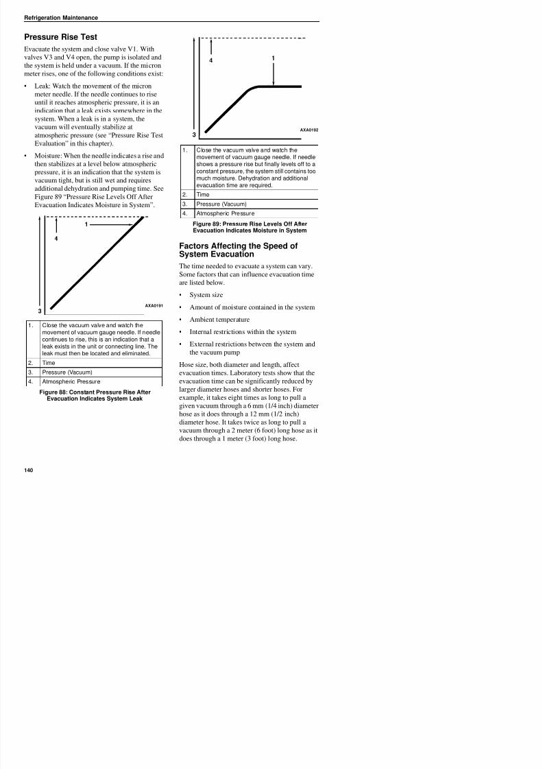
8/12/2019 Termo_King_Magnum_manual.pdf
http://slidepdf.com/reader/full/termokingmagnummanualpdf 140/194
y y ,
vacuum will eventually stabilize at
atmospheric pressure (see “Pressure Rise Test
Evaluation” in this chapter).
• Moisture: When the needle indicates a rise and
then stabilizes at a level below atmospheric
pressure, it is an indication that the system is
vacuum tight, but is still wet and requires
additional dehydration and pumping time. See
Figure 89 “Pressure Rise Levels Off After
Evacuation Indicates Moisture in System”.
Factors Affecting the Speed ofSystem Evacuation
The time needed to evacuate a system can vary.Some factors that can influence evacuation time
are listed below.
• System size
• Amount of moisture contained in the system
• Ambient temperature
• Internal restrictions within the system
• External restrictions between the system and
1. Close the vacuum valve and watch themovement of vacuum gauge needle. If needlecontinues to rise, this is an indication that aleak exists in the unit or connecting line. The
AXA0191
1. Close the vacuum valve and watch themovement of vacuum gauge needle. If needleshows a pressure rise but finally levels off to aconstant pressure, the system still contains toomuch moisture. Dehydration and additionalevacuation time are required.
2. Time
3. Pressure (Vacuum)4. Atmospheric Pressure
Figure 89: Pressure Rise Levels Off AfterEvacuation Indicates Moisture in System
AXA0192
Refrigeration Maintenance
Heat Saves Time
The application of heat to the system is a useful
and practical time saver. Increasing the
temperature of the compressor oil and refrigerant
will speed up the vaporization of any water
present in the system.
8. Set the refrigerant tank for liquid removal.
Open the hand valve on the tank.
9. Turn the unit off.
10. Open the gauge manifold hand valve and
charge liquid refrigerant into the system.
11. Close the refrigerant tank hand valve when the
correct amount (by weight) of refrigerant has
been added or if the system will take no more
liquid. The unit is now ready to have the
evacuation station removed
WARNING: Never use a torch or other
concentrated heat source to heat the
compressor or other refrigeration system
component.
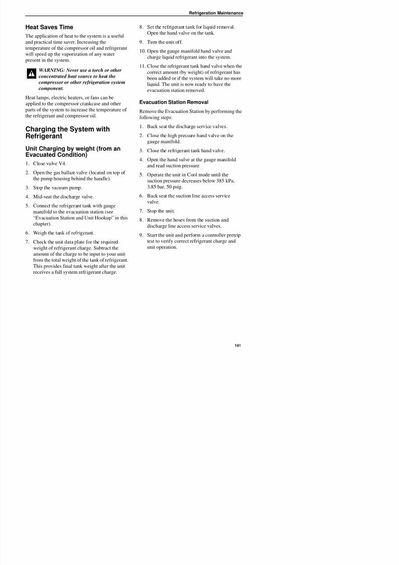
8/12/2019 Termo_King_Magnum_manual.pdf
http://slidepdf.com/reader/full/termokingmagnummanualpdf 141/194
Heat lamps, electric heaters, or fans can be
applied to the compressor crankcase and otherparts of the system to increase the temperature of
the refrigerant and compressor oil.
Charging the System withRefrigerant
Unit Charging by weight (from anEvacuated Condition)
1. Close valve V4.
2. Open the gas ballast valve (located on top of
the pump housing behind the handle).
3. Stop the vacuum pump.
4. Mid-seat the discharge valve.
5. Connect the refrigerant tank with gauge
manifold to the evacuation station (see
“Evacuation Station and Unit Hookup” in this
chapter).
6. Weigh the tank of refrigerant.
7. Check the unit data plate for the requiredweight of refrigerant charge. Subtract the
amount of the charge to be input to your unit
evacuation station removed.
Evacuation Station Removal
Remove the Evacuation Station by performing the
following steps:
1. Back seat the discharge service valves.
2. Close the high pressure hand valve on the
gauge manifold.
3. Close the refrigerant tank hand valve.
4. Open the hand valve at the gauge manifold
and read suction pressure.
5. Operate the unit in Cool mode until the
suction pressure decreases below 385 kPa,
3.85 bar, 50 psig.
6. Back seat the suction line access servicevalve.
7. Stop the unit.
8. Remove the hoses from the suction and
discharge line access service valves.
9. Start the unit and perform a controller pretrip
test to verify correct refrigerant charge andunit operation.
p
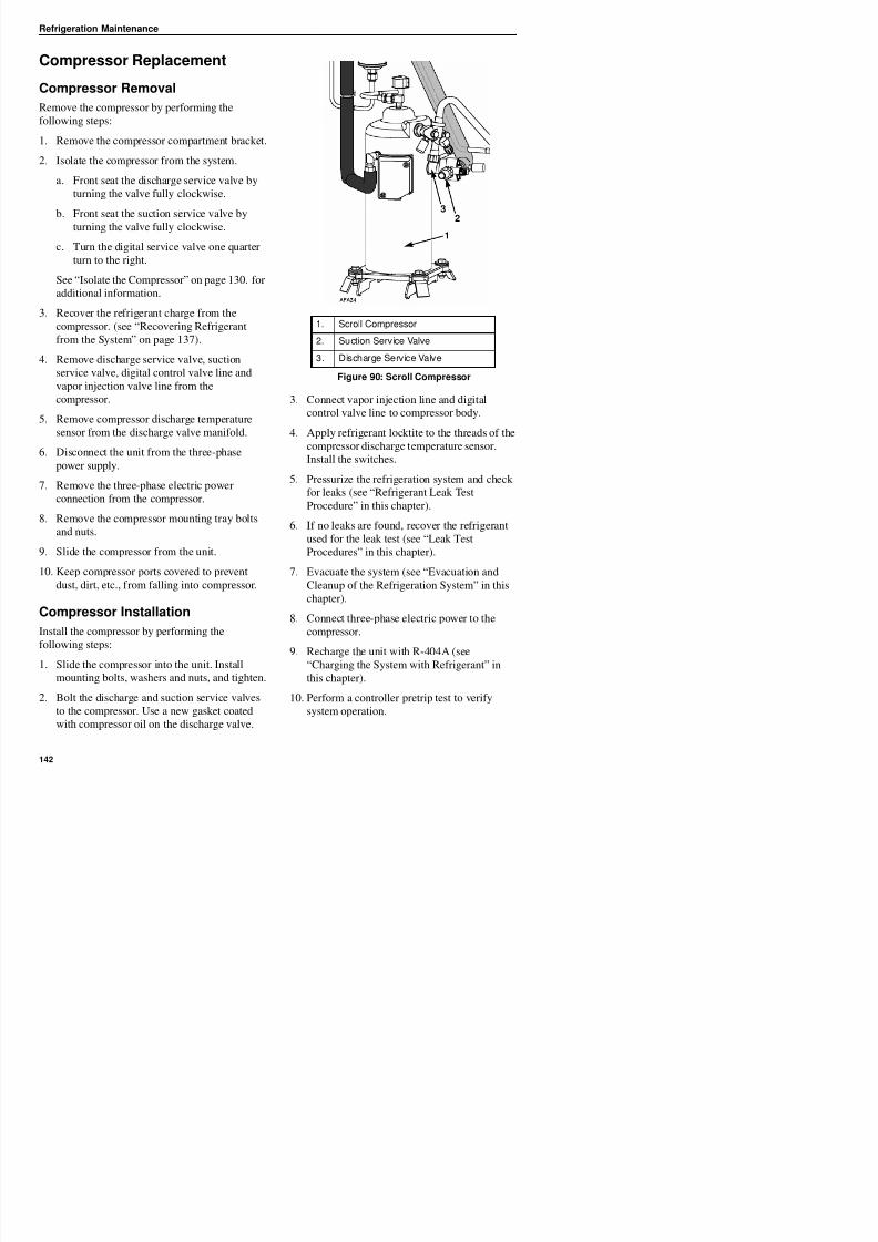
8/12/2019 Termo_King_Magnum_manual.pdf
http://slidepdf.com/reader/full/termokingmagnummanualpdf 142/194
Refrigeration Maintenance
Condenser Coil Replacement
Condenser Coil Removal
Remove the condenser coil by performing the
following steps:
1. Recover the refrigerant charge from the unit.
2. Remove the condenser fan grille, condenser
fan blade and condenser fan shroud.
3. Remove condenser coil support brackets from
Condenser Coil Installation
Install condenser coil by performing the following
steps:
1. Clean the tubes for soldering.
2. Slide the coil into the unit and install the boltsin the mounting brackets.
3. Solder the inlet line and liquid line
connections.
NOTE: It’s strongly recommended that dry
8/12/2019 Termo_King_Magnum_manual.pdf
http://slidepdf.com/reader/full/termokingmagnummanualpdf 143/194
coil.
4. Unsolder coil inlet and liquid lineconnections.
5. Support the coil and unbolt the condenser coil
mounting brackets. Slide coil from the unit.
NOTE: It s strongly recommended that dry
nitrogen be used to purge the system during
any solder operations (see “Using
Pressurized Nitrogen” in this chapter).
4. Perform a controller pretrip test to verify
system operation. Check compressor oil level.
5. Pressurize the system and test for leaks (see
“Refrigerant Leak Test Procedure” in this
chapter). Repair leak if required.
6. Recover the leak test gas if no leaks were
found.
7. Evacuate the system (see “Evacuation and
Cleanup of the Refrigeration System” in this
chapter).
8. Replace the condenser coil support brackets,
condenser fan shroud and condenser fan grille.
9. Recharge the unit with R-404A (see
“Charging the System with Refrigerant” in
this chapter).
Refrigeration Maintenance
Filter Drier/In-line FilterReplacement
Filter Drier/In-line Filter Removal
Remove the filter drier/in-line filter by performing
the following steps:
1. Recover the refrigerant charge from the unit.
2. Place the new filter drier near the unit for
immediate installation.
7. Recover the refrigerant used for the leak test if
no leaks were found.
8. Evacuate the system (see “Evacuation and
Cleanup of the Refrigeration System” in this
chapter).
9. Recharge the unit with R-404A (see
“Charging the System with Refrigerant” in
this chapter).
10. Perform a controller pretrip test to verify
system operation.
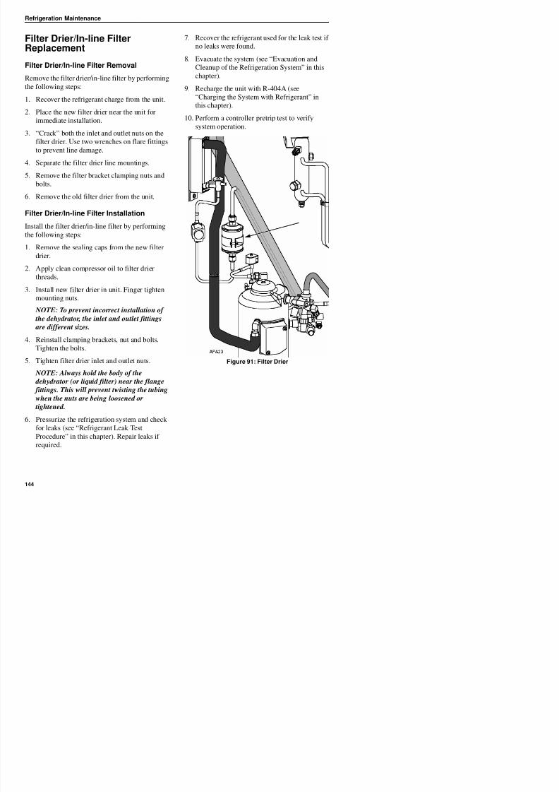
8/12/2019 Termo_King_Magnum_manual.pdf
http://slidepdf.com/reader/full/termokingmagnummanualpdf 144/194
3. “Crack” both the inlet and outlet nuts on the
filter drier. Use two wrenches on flare fittings
to prevent line damage.
4. Separate the filter drier line mountings.
5. Remove the filter bracket clamping nuts and
bolts.
6. Remove the old filter drier from the unit.
Filter Drier/In-line Filter Installation
Install the filter drier/in-line filter by performing
the following steps:
1. Remove the sealing caps from the new filter
drier.
2. Apply clean compressor oil to filter drier
threads.
3. Install new filter drier in unit. Finger tighten
mounting nuts.
NOTE: To prevent incorrect installation of
the dehydrator, the inlet and outlet fittings
are different sizes.
4. Reinstall clamping brackets, nut and bolts.Tighten the bolts.
5 Ti ht filt d i i l t d tl t t
y p
Refrigeration Maintenance
Evaporator Expansion Valve(TXV) Replacement
NOTE: TXV can be accessed through the
evaporator access door.
1. Perform a low side pump down or reclaimcharge depending on the unit. Release the 2-3
lbs pressure from the low side.
2. Open the evaporator access panel.
3. Install plywood or heavy cardboard on top of
7. Cut the one ty band off the insulation around
the element. Peel back the insulation to expose
the clamp holding the element. Loosen the
clamp and remove the element from the tube.
8. Unsolder the three tubes to the TXV and
remove the valve from the unit.
9. Prepare the tubes in the unit and on the new
TXV for installation.
10. Solder in the new TXV. Use 15% silver solder
203-364.
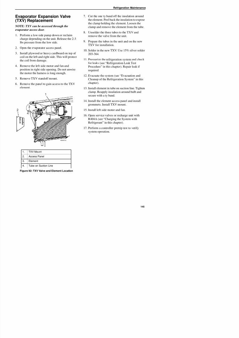
8/12/2019 Termo_King_Magnum_manual.pdf
http://slidepdf.com/reader/full/termokingmagnummanualpdf 145/194
coil on the left and right side. This will protect
the coil from damage.
4. Remove the left side motor and fan and
position in right side opening. Do not unwire
the motor the harness is long enough.
5. Remove TXV standoff mount.
6. Remove the panel to gain access to the TXV
element.
11. Pressurize the refrigeration system and check
for leaks (see “Refrigeration Leak TestProcedure” in this chapter). Repair leak if
required.
12. Evacuate the system (see “Evacuation and
Cleanup of the Refrigeration System” in this
chapter).
13. Install element in tube on suction line. Tighten
clamp. Reapply insulation around bulb and
secure with a ty band.
14. Install the element access panel and install
grommets. Install TXV mount.
15. Install left side motor and fan.
16. Open service valves or recharge unit with
R404A (see “Charging the System with
Refrigerant” in this chapter).
17. Perform a controller pretrip test to verify
system operation.
1. TXV Mount
Refrigeration Maintenance
Economizer Expansion ValveReplacement
Economizer Expansion Valve Removal
Remove the economizer expansion valve by
performing the following steps:
1. Recover the refrigerant charge from the unit
(see “Recovering Refrigerant from the
System” on page 137).
2. Unclamp feeler bulb from the suction line in 2
1
4
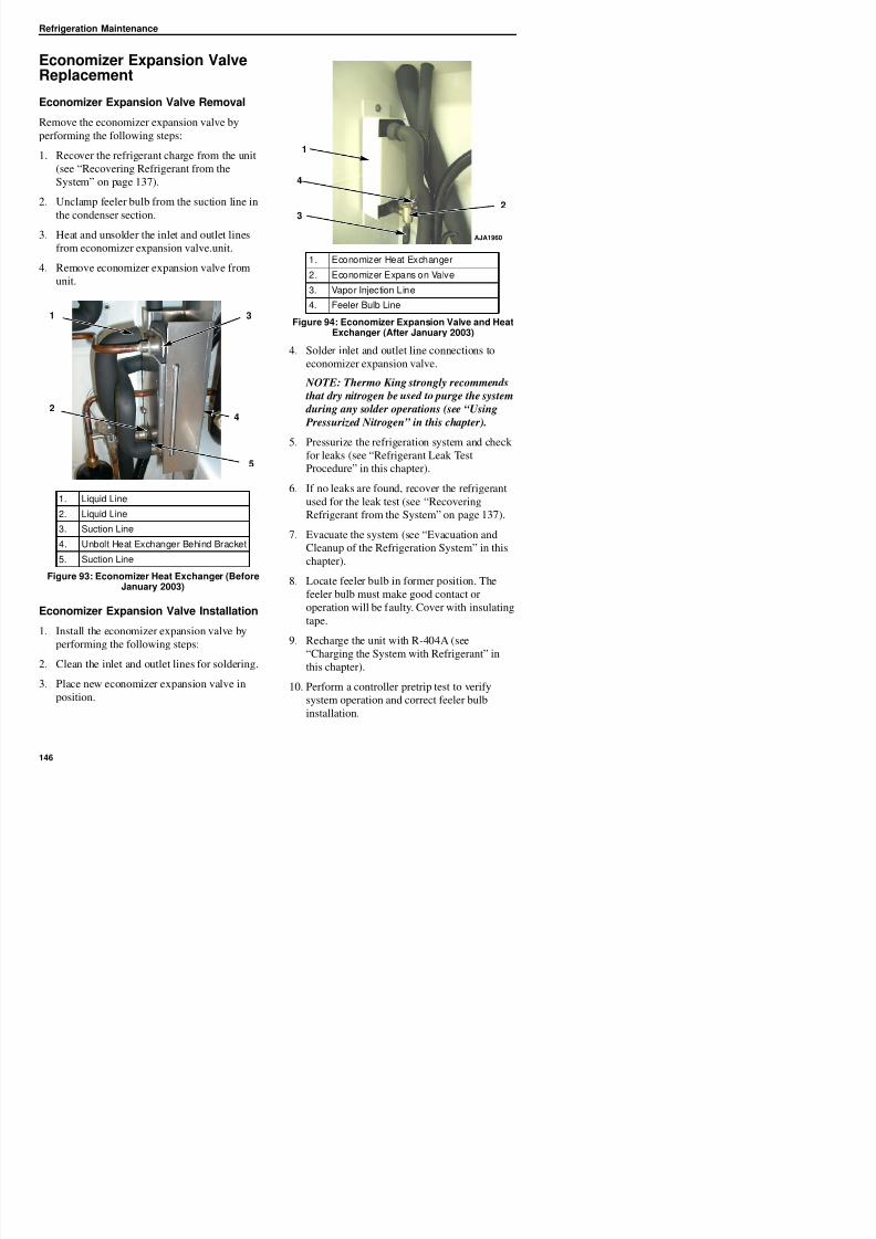
8/12/2019 Termo_King_Magnum_manual.pdf
http://slidepdf.com/reader/full/termokingmagnummanualpdf 146/194
2. Unclamp feeler bulb from the suction line in
the condenser section.
3. Heat and unsolder the inlet and outlet linesfrom economizer expansion valve.unit.
4. Remove economizer expansion valve from
unit.
4. Solder inlet and outlet line connections to
economizer expansion valve.
NOTE: Thermo King strongly recommends
that dry nitrogen be used to purge the system
during any solder operations (see “Using
Pressurized Nitrogen” in this chapter).
5. Pressurize the refrigeration system and check
for leaks (see “Refrigerant Leak Test
Procedure” in this chapter).
6. If no leaks are found, recover the refrigerant
used for the leak test (see “Recovering
Refrigerant from the System” on page 137).
7. Evacuate the system (see “Evacuation and
Cleanup of the Refrigeration System” in this
chapter)
1. Liquid Line
2. Liquid Line
3. Suction Line4. Unbolt Heat Exchanger Behind Bracket
5. Suction Line
1
2
3
4
5
1. Economizer Heat Exchanger
2. Economizer Expansion Valve
3. Vapor Injection Line
4. Feeler Bulb Line
Figure 94: Economizer Expansion Valve and Heat
Exchanger (After January 2003)
23
AJA1960
Refrigeration Maintenance
Economizer Heat ExchangerReplacement
Economizer Heat ExchangerRemoval
Remove the economizer heat exchanger byperforming the following steps:
1. Recover the refrigerant charge from the unit
(see “Recovering Refrigerant” in this chapter).
2. Unsolder the two liquid and two suction line
NOTE: Thermo King strongly recommends
that dry nitrogen be used to purge the system
during any solder operations (see “Using
Pressurized Nitrogen” in this chapter).
4. Pressurize the low side and check for leaks
(see “Refrigerant Leak Test Procedure” in thischapter).
5. If no leaks are found, recover the leak test gas
(see “Refrigerant Leak Test Procedure” in this
chapter).
8/12/2019 Termo_King_Magnum_manual.pdf
http://slidepdf.com/reader/full/termokingmagnummanualpdf 147/194
q
connections.
3. Unbolt the economizer heat exchanger fromthe mounting bracket.
4. Lift the heat exchanger assembly from the
unit.
Economizer Heat Exchangerinstallation
Install the heat exchanger by performing the
following steps:
1. Bolt the economizer heat exchanger to the
mounting bracket in the condenser section.
2. Clean the two liquid and two suction lines for
soldering.
3. Solder the liquid and suction lines to the
economizer heat exchanger.
6. Evacuate the low side (see “Evacuation and
Cleanup of the Refrigeration System” in this
chapter).
7. Recharge the unit with R-404A (see
“Charging the System with Refrigerant” in
this chapter).
8. Perform a controller pretrip test to verify
system operation.
Refrigeration Maintenance
Receiver Tank/ Water-CooledCondenser Tank Replacement
Tank Removal
Remove the old tank by performing the following
steps:
1. Recover the refrigerant charge from the unit.
2. Unsolder the liquid inlet and liquid outlet
valve line connections.
3 Loosen the mounting nuts and remove the
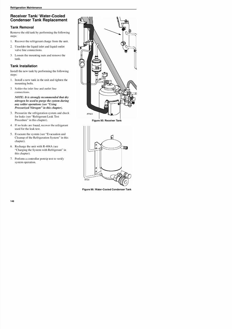
8/12/2019 Termo_King_Magnum_manual.pdf
http://slidepdf.com/reader/full/termokingmagnummanualpdf 148/194
3. Loosen the mounting nuts and remove the
tank.
Tank Installation
Install the new tank by performing the following
steps:
1. Install a new tank in the unit and tighten the
mounting bolts.
2. Solder the inlet line and outlet lineconnections.
NOTE: It is strongly recommended that dry
nitrogen be used to purge the system during
any solder operations (see “Using
Pressurized Nitrogen” in this chapter).
3. Pressurize the refrigeration system and checkfor leaks (see “Refrigerant Leak Test
Procedure” in this chapter).
4. If no leaks are found, recover the refrigerant
used for the leak test.
5. Evacuate the system (see “Evacuation and
Cleanup of the Refrigeration System” in this
chapter).
6. Recharge the unit with R-404A (see
“Ch i th S t ith R f i t” i
Figure 95: Receiver Tank
Refrigeration Maintenance
Valve Installation
To install the vapor injection valve, perform the
following steps:
1. Clean the tubes for soldering.
2. Place the new valve in position and solder theliquid line connections.
CAUTION: Use a heat sink or wrap
switch with wet rags to prevent damage to
new switch.
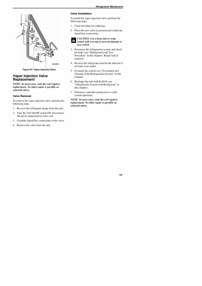
8/12/2019 Termo_King_Magnum_manual.pdf
http://slidepdf.com/reader/full/termokingmagnummanualpdf 149/194
Figure 97: Vapor Injection Valve
Vapor Injection ValveReplacement NOTE: In most cases, only the coil requires
replacement. No other repair is possible on
solenoid valves.
Valve Removal
To remove the vapor injection valve, perform the
following steps:
1. Recover the refrigerant charge from the unit.
2. Turn the Unit On/Off switch Off. Disconnect
electrical connections to valve coil.
3. Unsolder liquid line connections to the valve.
4. Remove the valve from the unit.
3. Pressurize the refrigeration system and check
for leaks (see “Refrigerant Leak Test
Procedure” in this chapter). Repair leak if
required.
4. Recover the refrigerant used for the leak test if
no leaks were found.
5. Evacuate the system (see “Evacuation and
Cleanup of the Refrigeration System” in this
chapter).
6. Recharge the unit with R-404A (see
“Charging the System with Refrigerant” in
this chapter).
7. Perform a controller pretrip test to verify
system operation.
NOTE: In most cases, only the coil requires replacement. No other repair is possible on
solenoid valves.
AJA2032
Refrigeration Maintenance
Compressor Digital ControlValve Replacement
Digital Control Valve Removal
To remove the compressor digital control valve,
perform the following steps:
1. Isolate the compressor and digital valve from
the system.
a. Front seat the discharge service valve by
turning the valve fully clockwise.
5
1
4
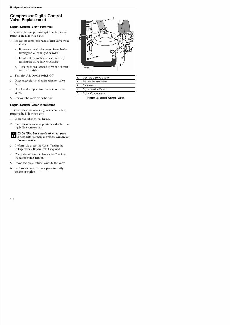
8/12/2019 Termo_King_Magnum_manual.pdf
http://slidepdf.com/reader/full/termokingmagnummanualpdf 150/194
b. Front seat the suction service valve by
turning the valve fully clockwise.
c. Turn the digital service valve one quarter
turn to the right.
2. Turn the Unit On/Off switch Off.
3. Disconnect electrical connections to valve
coil.
4. Unsolder the liquid line connections to the
valve.
5. Remove the valve from the unit.
Digital Control Valve Installation
To install the compressor digital control valve,
perform the following steps:
1. Clean the tubes for soldering.
2. Place the new valve in position and solder the
liquid line connections.
3. Perform a leak test (see Leak Testing the
CAUTION: Use a heat sink or wrap the
switch with wet rags to prevent damage to
the new switch.
1. Discharge Service Valve
2. Suction Service Valve
3. Compressor
4. Digital Service Valve
5. Digital Control Valve
Figure 98: Digital Control Valve
23
Servicing The Unit
Taking Care of the Structure
Inspecting the Unit
Inspect the unit during unit pretrip inspection and
every 1,000 operating hours for loose or brokenwires or hardware, compressor oil leaks, or other
physical damage which can affect unit
performance and require repair or replacement of
parts.
Cleaning the Condenser Coil
Clean the condenser coil by blowing low pressure
compressed air or a medium pressure warm water
spray from the inside of the coil outward (opposite
direction of normal airflow). Inspect coil and finsfor damage and repair if necessary.
CAUTION: Air pressure or water spray
must not be high enough to damage coil
fins
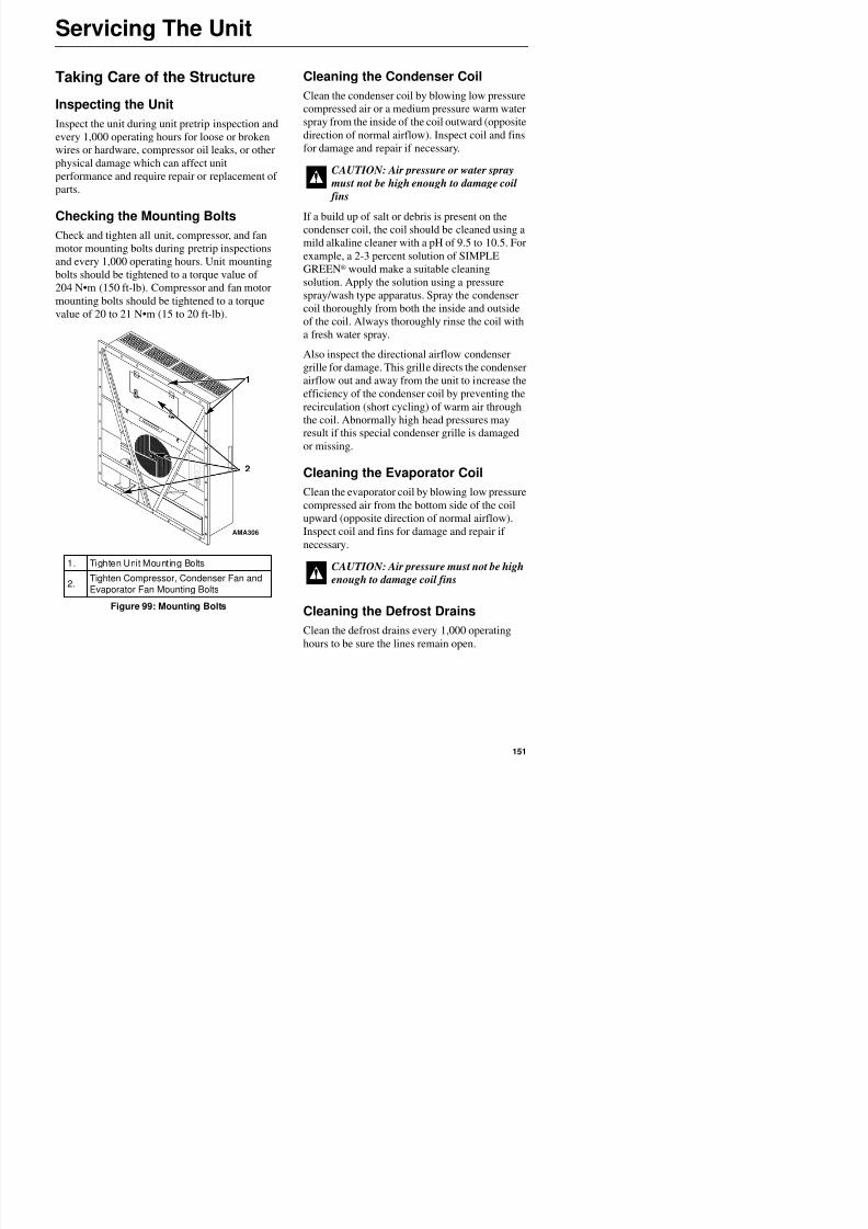
8/12/2019 Termo_King_Magnum_manual.pdf
http://slidepdf.com/reader/full/termokingmagnummanualpdf 151/194
Checking the Mounting Bolts
Check and tighten all unit, compressor, and fanmotor mounting bolts during pretrip inspections
and every 1,000 operating hours. Unit mounting
bolts should be tightened to a torque value of
204 N•m (150 ft-lb). Compressor and fan motor
mounting bolts should be tightened to a torque
value of 20 to 21 N•m (15 to 20 ft-lb).
If a build up of salt or debris is present on the
condenser coil, the coil should be cleaned using amild alkaline cleaner with a pH of 9.5 to 10.5. For
example, a 2-3 percent solution of SIMPLE
GREEN® would make a suitable cleaning
solution. Apply the solution using a pressure
spray/wash type apparatus. Spray the condenser
coil thoroughly from both the inside and outside
of the coil. Always thoroughly rinse the coil with
a fresh water spray.
Also inspect the directional airflow condenser
grille for damage. This grille directs the condenser
airflow out and away from the unit to increase the
efficiency of the condenser coil by preventing the
recirculation (short cycling) of warm air through
the coil. Abnormally high head pressures may
result if this special condenser grille is damaged
or missing.
Cleaning the Evaporator Coil
Clean the evaporator coil by blowing low pressure
compressed air from the bottom side of the coil
upward (opposite direction of normal airflow).
Inspect coil and fins for damage and repair if
necessary.
1
2
AMA306
Servicing The Unit
Positioning the Condenser FanBlade
Place fan blade on motor shaft with hub located
on the outside of the blade for proper airflow
direction. When mounting the fan blade and hub
assembly on the fanshaft, center the assembly inthe orifice. Position the front of the fan blade
10 mm (0.4 in.) in from the outer edge of the fan
orifice.
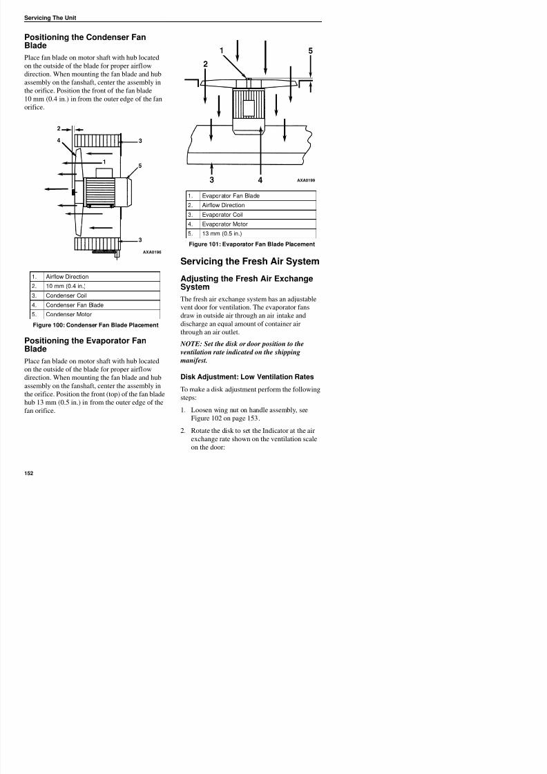
8/12/2019 Termo_King_Magnum_manual.pdf
http://slidepdf.com/reader/full/termokingmagnummanualpdf 152/194
Positioning the Evaporator FanBlade
Servicing the Fresh Air System
Adjusting the Fresh Air ExchangeSystem
The fresh air exchange system has an adjustable
vent door for ventilation. The evaporator fans
draw in outside air through an air intake and
discharge an equal amount of container air
through an air outlet.
NOTE: Set the disk or door position to the
til ti t i di t d th hi i
1. Airflow Direction
2. 10 mm (0.4 in.)
3. Condenser Coil
4. Condenser Fan Blade
5. Condenser Motor
Figure 100: Condenser Fan Blade Placement
AXA0196
1. Evaporator Fan Blade
2. Airflow Direction3. Evaporator Coil
4. Evaporator Motor
5. 13 mm (0.5 in.)
Figure 101: Evaporator Fan Blade Placement
AXA0199
Servicing The Unit
• MAGNUM 20 Model: 0 to 160 m3 /hr. (0
and 96 ft3 /min.).
• MAGNUM SL and MAGNUM Models: 0
to 125 m3 /hr. (0 and 75 ft3 /min.).
3. Tighten the wing nut.
Handle Adjustment: High VentilationRates
To make a handle adjustment, perform the
following steps:
1 L i h dl bl il
2 3
5
6
7
41
AXA0195
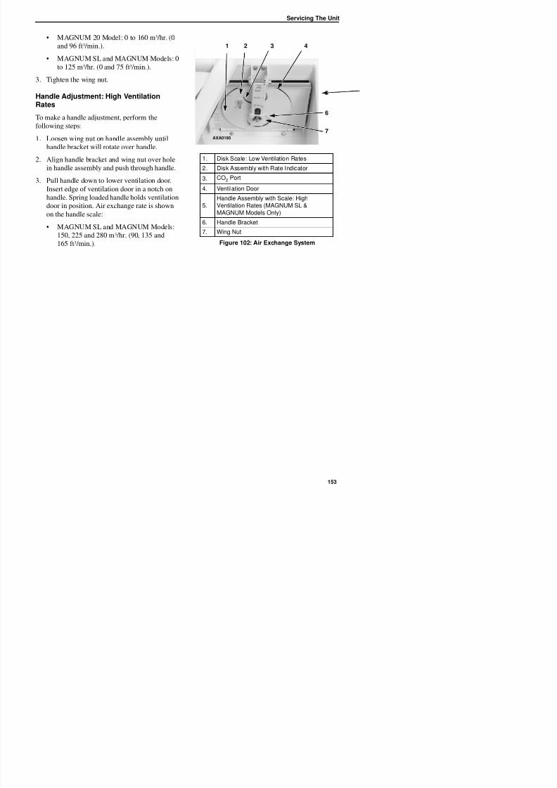
8/12/2019 Termo_King_Magnum_manual.pdf
http://slidepdf.com/reader/full/termokingmagnummanualpdf 153/194
1. Loosen wing nut on handle assembly until
handle bracket will rotate over handle.2. Align handle bracket and wing nut over hole
in handle assembly and push through handle.
3. Pull handle down to lower ventilation door.
Insert edge of ventilation door in a notch on
handle. Spring loaded handle holds ventilation
door in position. Air exchange rate is shown
on the handle scale:
• MAGNUM SL and MAGNUM Models:
150, 225 and 280 m3 /hr. (90, 135 and
165 ft3 /min.).
1. Disk Scale: Low Ventilation Rates
2. Disk Assembly with Rate Indicator
3. CO2 Port
4. Ventilation Door
5.Handle Assembly with Scale: HighVentilation Rates (MAGNUM SL &
MAGNUM Models Only)
6. Handle Bracket
7. Wing Nut
Figure 102: Air Exchange System
AXA0195
Servicing The Unit

8/12/2019 Termo_King_Magnum_manual.pdf
http://slidepdf.com/reader/full/termokingmagnummanualpdf 154/194
Diagnosis: Troubleshooting, StatusMessages, Alarm Codes
Introduction
This chapter includes the following:
• Introduction to Controller Diagnostics
• Troubleshooting charts
• Status Messages chart
• Alarm Codes chart
Full PTI Test: The MP-3000a controller contains a
special Full PTI pretrip test that automatically
checks unit refrigeration capacity, heating
capacity, temperature control, and individual
components including the controller display,
contactors, fans, protection devices and sensors.
The test includes measurement of component
power consumption and compares test results to
expected values. The test takes up to 2 to 2.5
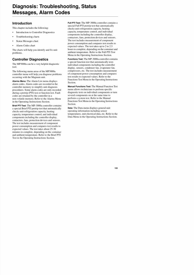
8/12/2019 Termo_King_Magnum_manual.pdf
http://slidepdf.com/reader/full/termokingmagnummanualpdf 155/194
The charts will help you identify and fix unit
problems.
Controller Diagnostics
The MP3000a can be a very helpful diagnostic
tool.
The following menu areas of the MP3000a
controller menu will help you diagnose problemsoccurring with the Magnum unit.
Alarms Menu: The Alarm List menu displays
alarm codes. Alarm codes are recorded in the
controller memory to simplify unit diagnosis
procedures. Some alarm codes are only recorded
during a pretrip (PTI) test or function test. Fault
codes are retained by the controller in anon-volatile memory. Refer to the Alarms Menu
in the Operating Instructions Section.
Brief PTI Test: The MP-3000a controller contains
a special Brief PTI pretrip test that automatically
checks unit refrigeration capacity, heating
capacity, temperature control, and individual
components including the controller display,contactors, fans, protection devices and sensors.
The test includes measurement of component
hours to complete, depending on the container and
ambient temperature. Refer to the Full PTI TestMenu in the Operating Instructions Section.
Functions Test: The MP-3000a controller contains
a special function test that automatically tests
individual components including the controller
display, sensors, condenser fan, evaporator fan,
compressors, etc. The test includes measurement
of component power consumption and comparestest results to expected values. Refer to the
Functions Test Menu in the Operating Instructions
Section.
Manual Functions Test: The Manual Function Test
menu allows technicians to perform specific
diagnostic tests on individual components or turn
several components on at the same time toperform a system test. Refer to the Manual
Functions Test Menu in the Operating Instructions
Section.
Data: The Data menu displays general unit
operating information including sensor
temperatures, unit electrical data, etc. Refer to the
Data Menu in the Operating Instructions Section.
Diagnosis: Troubleshooting, Status Messages, Alarm Codes
Troubleshooting Mechanical Problems
Condition Possible Cause Remedy
Compressor does not operate—no amperage draw
Controller on; unit start sequence stilltiming
Wait up to 2 minutes for compressorstart-up
No power to unit (condenser andevaporator fans do not operate)
Locate fault and repair: power
source, power plug, CB1 maincircuit breaker, motor contactor,motor terminals, motor
Open in 29 Vac control circuitCheck fuses and On/Off switch.Replace or repair as required
Container temperature does notdemand compressor operation
Adjust controller setpoint
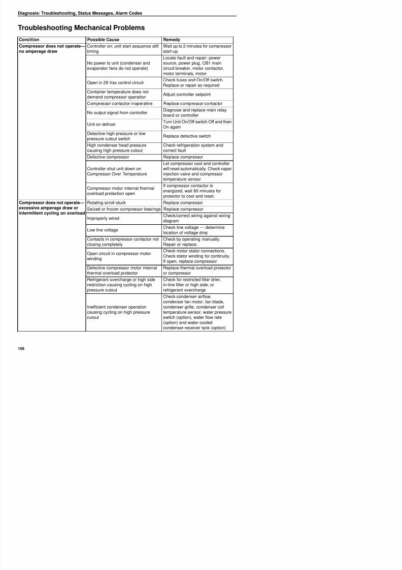
8/12/2019 Termo_King_Magnum_manual.pdf
http://slidepdf.com/reader/full/termokingmagnummanualpdf 156/194
Compressor contactor inoperative Replace compressor contactor
No output signal from controllerDiagnose and replace main relayboard or controller
Unit on defrostTurn Unit On/Off switch Off and thenOn again
Detective high pressure or lowpressure cutout switch
Replace defective switch
High condenser head pressurecausing high pressure cutout
Check refrigeration system andcorrect fault
Defective compressor Replace compressor
Controller shut unit down onCompressor Over Temperature
Let compressor cool and controllerwill reset automatically. Check vaporinjection valve and compressortemperature sensor
Compressor motor internal thermaloverload protection open
If compressor contactor isenergized, wait 60 minutes forprotector to cool and reset.
Compressor does not operate—excessive amperage draw orintermittent cycling on overload
Rotating scroll stuck Replace compressor
Seized or frozen compressor bearings Replace compressor
Improperly wiredCheck/correct wiring against wiringdiagram
Low line voltageCheck line voltage — determinelocation of voltage drop
Contacts in compressor contactor not
closing completely
Check by operating manually.
Repair or replace.
Open circuit in compressor motorwinding
Check motor stator connections.Check stator winding for continuity.
Diagnosis: Troubleshooting, Status Messages, Alarm Codes
Compressor contactor burnedout
Low line voltageIncrease line voltage to at least 90percent of compressor motor rating
Excessive line voltageReduce line voltage to at least 110percent of compressor motor rating
Short cycling Eliminate cause of short cycling
Unit short cycles Refrigerant overcharge causingcycling on high pressure cutout
Purge system
Inefficient condenser operationcausing cycling on high pressurecutout
Check condenser airflow,condenser fan motor, condenser fangrille, condenser fan pressureswitch, water pressure switch(option), water flow rate (option) and
ater cooled condenser recei er
Condition Possible Cause Remedy
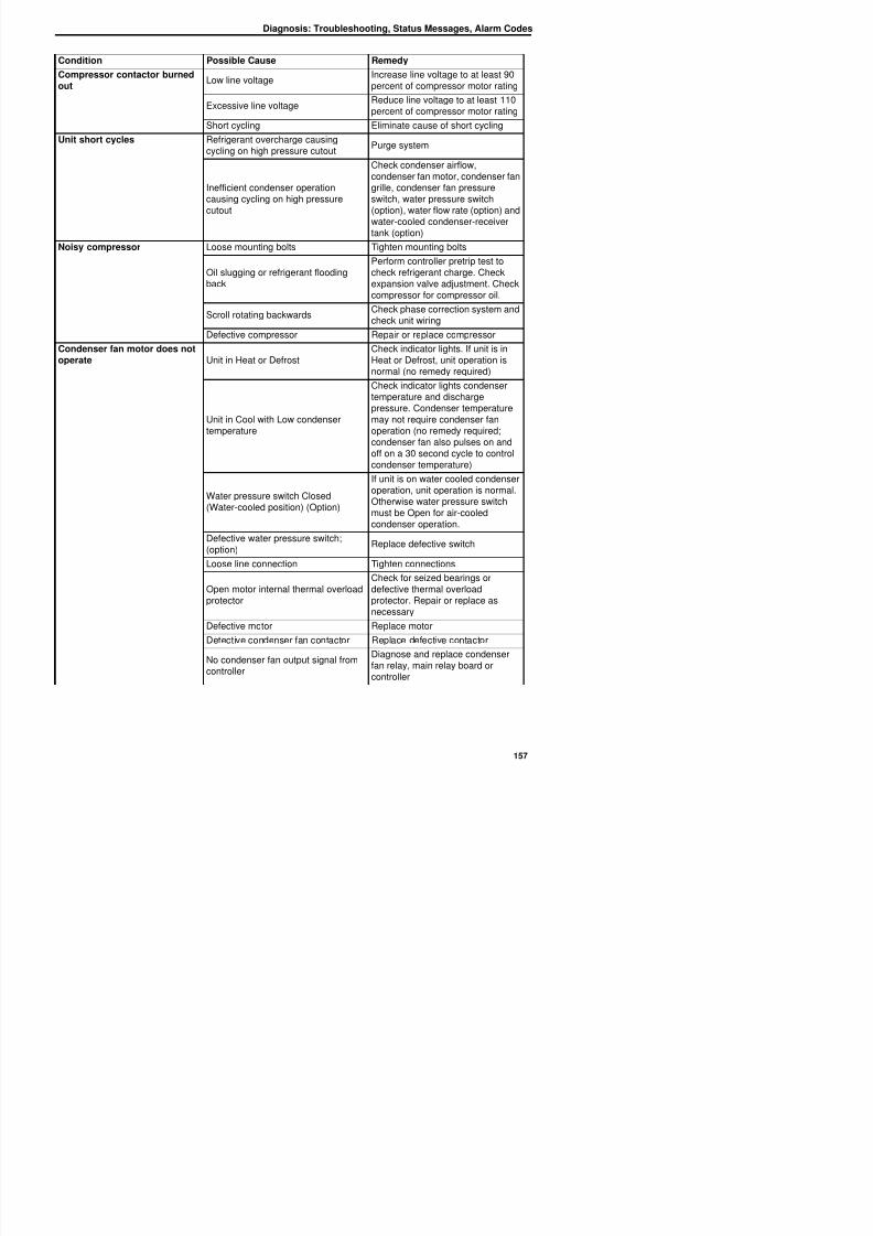
8/12/2019 Termo_King_Magnum_manual.pdf
http://slidepdf.com/reader/full/termokingmagnummanualpdf 157/194
water-cooled condenser-receiver
tank (option)Noisy compressor Loose mounting bolts Tighten mounting bolts
Oil slugging or refrigerant floodingback
Perform controller pretrip test tocheck refrigerant charge. Checkexpansion valve adjustment. Checkcompressor for compressor oil.
Scroll rotating backwardsCheck phase correction system andcheck unit wiring
Defective compressor Repair or replace compressorCondenser fan motor does notoperate Unit in Heat or Defrost
Check indicator lights. If unit is inHeat or Defrost, unit operation isnormal (no remedy required)
Unit in Cool with Low condenser
temperature
Check indicator lights condensertemperature and dischargepressure. Condenser temperaturemay not require condenser fan
operation (no remedy required;condenser fan also pulses on andoff on a 30 second cycle to controlcondenser temperature)
Water pressure switch Closed(Water-cooled position) (Option)
If unit is on water cooled condenseroperation, unit operation is normal.Otherwise water pressure switchmust be Open for air-cooledcondenser operation.
Defective water pressure switch;(option)
Replace defective switch
L li i Ti h i
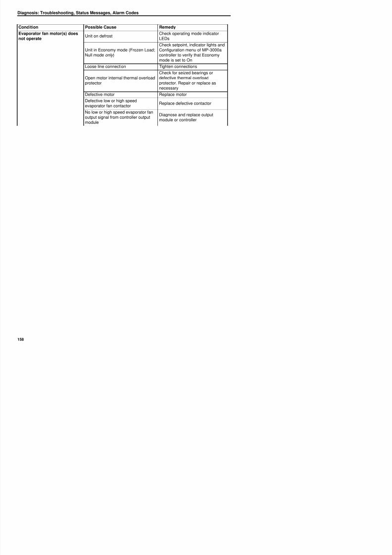
8/12/2019 Termo_King_Magnum_manual.pdf
http://slidepdf.com/reader/full/termokingmagnummanualpdf 158/194
Diagnosis: Troubleshooting, Status Messages, Alarm Codes
Troubleshooting Refrigeration Problems
Condition Possible Cause Remedy
Load temperature too high—unit not cooling
Compressor does not operate See “Mechanical Diagnosis”
Controller setpoint too high Adjust controller setpoint
Defective container insulation or poor
fitting doors Repair container
Shortage of refrigerant Repair leak and recharge
Overcharge of refrigerant Purge system
Air in refrigeration system Evacuate and recharge
Vapor injection valve openCheck vapor injection valve circuitand compressor dischargetemperature sensor
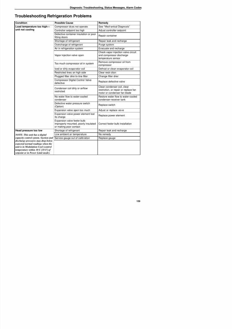
8/12/2019 Termo_King_Magnum_manual.pdf
http://slidepdf.com/reader/full/termokingmagnummanualpdf 159/194
p
Too much compressor oil in system Remove compressor oil fromcompressor
Iced or dirty evaporator coil Defrost or clean evaporator coil
Restricted lines on high side Clear restriction
Plugged filter drier/in-line filter Change filter drier
Compressor Digital Control Valvedefective
Replace defective valve
Condenser coil dirty or airflowrestricted
Clean condenser coil, clear
restriction, or repair or replace fanmotor or condenser fan blade
No water flow to water-cooledcondenser
Restore water flow to water-cooledcondenser-receiver tank
Defective water pressure switch(Option)
Replace switch
Expansion valve open too much Adjust or replace valve
Expansion valve power element lostits charge Replace power element
Expansion valve feeler bulbimproperly mounted, poorly insulatedor making poor contact
Correct feeler bulb installation
Head pressure too low
NOTE: This unit has a digital
capacity control system. Suction and
discharge pressures may drop belowexpected normal readings when the
unit is in Modulation Cool (control
t t ithi 10 C [18 F] f
Shortage of refrigerant Repair leak and recharge
Low ambient air temperature No remedy
Service gauge out of calibration Replace gauge
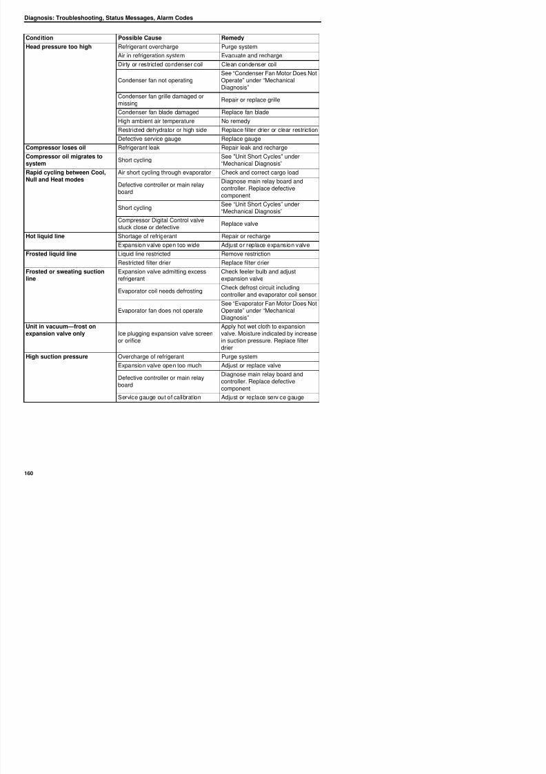
8/12/2019 Termo_King_Magnum_manual.pdf
http://slidepdf.com/reader/full/termokingmagnummanualpdf 160/194
Diagnosis: Troubleshooting, Status Messages, Alarm Codes
Low suction pressure
NOTE: This unit has a capacity
control system. Suction and
discharge pressures may drop below
expected normal readings when the
unit is on Modulation Cool (control temperature within 10 C [18 F] of
setpoint or in Power Limit mode).
Shortage of refrigerant Repair leak and recharge
Low ambient air temperature No remedy
Iced or dirty evaporator coil Defrost or clean evaporator coil
Restricted lines Locate and clear restriction
Plugged filter drier Replace filter drier
Expansion valve closed too much Adjust or replace valve
Expansion valve feeler bulbimproperly mounted, poorly insulatedor making poor contact
Correct feeler bulb installation
Evaporator fans offCheck evaporator fan motors andcontrol circuit and correct fault
Defective controller or main relayDiagnose main relay board and
Condition Possible Cause Remedy
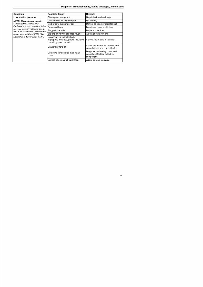
8/12/2019 Termo_King_Magnum_manual.pdf
http://slidepdf.com/reader/full/termokingmagnummanualpdf 161/194
Defective controller or main relay
board
g y
controller. Replace defectivecomponent
Service gauge out of calibration Adjust or replace gauge
Diagnosis: Troubleshooting, Status Messages, Alarm Codes
Status Messages andController Actions
The controller displays status messages (In the
Miscellaneous Function Menu under Status) on
the LCD display for several general faults. More
than one status message may appear at a time.
Press the F2 or F3 key to scroll through message
displays.
Status Messages and Controller ActionsMessage
No.Status Message Controller Action
1
Power Error, Check 20A Fuses
Indicates:
• One or more phases are missing
• Compressor is able to draw amps on all
• Controller activates Alarm 18
• Controller will try to restart unit after 60 minutes.
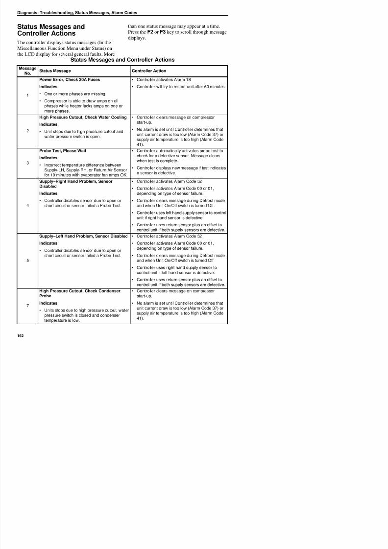
8/12/2019 Termo_King_Magnum_manual.pdf
http://slidepdf.com/reader/full/termokingmagnummanualpdf 162/194
• Compressor is able to draw amps on all
phases while heater lacks amps on one ormore phases.
2
High Pressure Cutout, Check Water Cooling
Indicates:
• Unit stops due to high pressure cutout andwater pressure switch is open.
• Controller clears message on compressorstart-up.
• No alarm is set until Controller determines thatunit current draw is too low (Alarm Code 37) orsupply air temperature is too high (Alarm Code41).
3
Probe Test, Please Wait
Indicates:
• Incorrect temperature difference betweenSupply-LH, Supply-RH, or Return Air Sensorfor 10 minutes with evaporator fan amps OK.
• Controller automatically activates probe test tocheck for a defective sensor. Message clearswhen test is complete.
• Controller displays new message if test indicatesa sensor is defective.
4
Supply–Right Hand Problem, SensorDisabled
Indicates:
• Controller disables sensor due to open orshort circuit or sensor failed a Probe Test.
• Controller activates Alarm Code 52
• Controller activates Alarm Code 00 or 01,
depending on type of sensor failure.
• Controller clears message during Defrost modeand when Unit On/Off switch is turned Off.
• Controller uses left hand supply sensor to controlunit if right hand sensor is defective.
• Controller uses return sensor plus an offset tocontrol unit if both supply sensors are defective.
Supply–Left Hand Problem, Sensor Disabled
Indicates:
C ll di bl d
• Controller activates Alarm Code 52
• Controller activates Alarm Code 00 or 01,depending on type of sensor failure
Diagnosis: Troubleshooting, Status Messages, Alarm Codes
8
Running with High Supply Difference
Indicates:
• Temperature difference between the left handand right hand Supply sensors is too large;even after Probe Test indicates no sensorerrors.
• Possible causes include air leak aroundsensor cable, low refrigerant charge, defectiveexpansion valve, etc.
• Controller clears message during defrost andwhen Unit On/Off switch is turned Off.
High Pressure Cutout, Check Condenser Fan • Controller clears message on compressor
Status Messages and Controller Actions (Continued)
MessageNo.
Status Message Controller Action
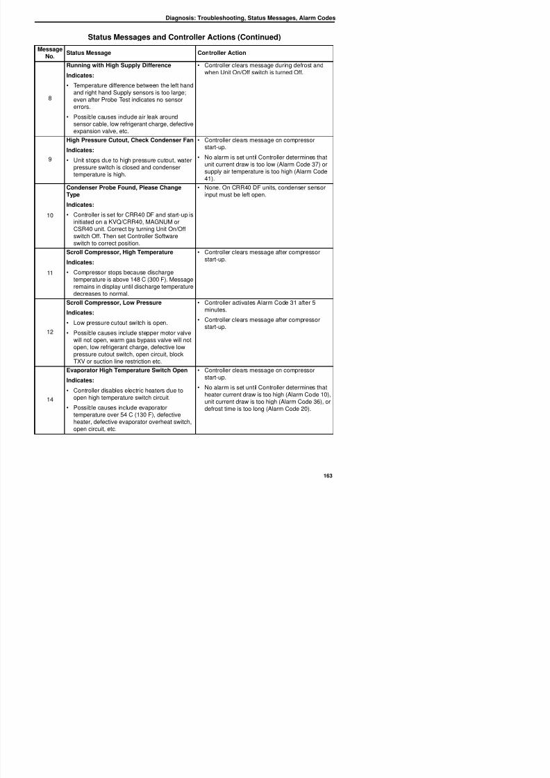
8/12/2019 Termo_King_Magnum_manual.pdf
http://slidepdf.com/reader/full/termokingmagnummanualpdf 163/194
9
Indicates:
• Unit stops due to high pressure cutout, waterpressure switch is closed and condensertemperature is high.
start-up.• No alarm is set until Controller determines that
unit current draw is too low (Alarm Code 37) orsupply air temperature is too high (Alarm Code41).
10
Condenser Probe Found, Please ChangeType
Indicates:
• Controller is set for CRR40 DF and start-up isinitiated on a KVQ/CRR40, MAGNUM orCSR40 unit. Correct by turning Unit On/Offswitch Off. Then set Controller Softwareswitch to correct position.
• None. On CRR40 DF units, condenser sensorinput must be left open.
11
Scroll Compressor, High Temperature
Indicates:
• Compressor stops because dischargetemperature is above 148 C (300 F). Messageremains in display until discharge temperaturedecreases to normal.
• Controller clears message after compressorstart-up.
12
Scroll Compressor, Low Pressure
Indicates:
• Low pressure cutout switch is open.
• Possible causes include stepper motor valvewill not open, warm gas bypass valve will notopen, low refrigerant charge, defective low
t t it h i it bl k
• Controller activates Alarm Code 31 after 5minutes.
• Controller clears message after compressorstart-up.
Diagnosis: Troubleshooting, Status Messages, Alarm Codes
21 Total Current Too High(Check Alarm)
• When the unit or component current draw is25 percent above expected amps for 4minutes.
• Indicates:
• Digital Control valve malfunction
• Compressor, evaporator fan motor,condenser fan motor or heater current toohigh
• Enter Manual Function Test menu and test(operate) each component. Check volts andamps to determine which component has high
amp draw.
• Check power supply volts.
• Check volt and ampere meter.
Status Messages and Controller Actions (Continued)
MessageNo.
Status Message Controller Action
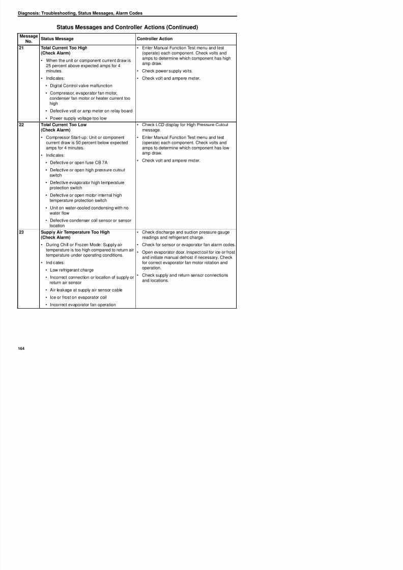
8/12/2019 Termo_King_Magnum_manual.pdf
http://slidepdf.com/reader/full/termokingmagnummanualpdf 164/194
• Defective volt or amp meter on relay board
• Power supply voltage too low
22 Total Current Too Low(Check Alarm)
• Compressor Start-up: Unit or componentcurrent draw is 50 percent below expectedamps for 4 minutes.
• Indicates:
• Defective or open fuse CB 7A
• Defective or open high pressure cutoutswitch
• Defective evaporator high temperatureprotection switch
• Defective or open motor internal high
temperature protection switch
• Unit on water-cooled condensing with nowater flow
• Defective condenser coil sensor or sensorlocation
• Check LCD display for High Pressure Cutoutmessage.
• Enter Manual Function Test menu and test(operate) each component. Check volts andamps to determine which component has low
amp draw.• Check volt and ampere meter.
23 Supply Air Temperature Too High(Check Alarm)
• During Chill or Frozen Mode: Supply airtemperature is too high compared to return airtemperature under operating conditions.
• Check discharge and suction pressure gaugereadings and refrigerant charge.
• Check for sensor or evaporator fan alarm codes.• Open evaporator door. Inspect coil for ice or frost
and initiate manual defrost if necessary. Check
Diagnosis: Troubleshooting, Status Messages, Alarm Codes
24 Supply Air Temperature Too Low(Check Alarm)
• During Chill or Frozen Mode: Supply air
temperature is too low compared to return airtemperature under operating conditions.
• Indicates:
• Ice or frost on evaporator coil
• Low heating capacity
• Incorrect evaporator fan operation
• Check for sensor or evaporator fan alarm codes.
• Open evaporator door. Inspect coil for ice or frostand initiate manual defrost if necessary. Check
for correct evaporator fan motor rotation andoperation.
• Check supply and return sensor connectionsand locations.
Status Messages and Controller Actions (Continued)
MessageNo.
Status Message Controller Action
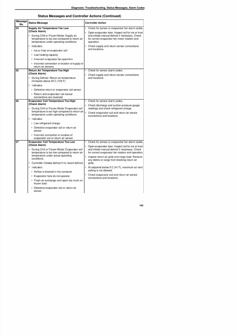
8/12/2019 Termo_King_Magnum_manual.pdf
http://slidepdf.com/reader/full/termokingmagnummanualpdf 165/194
• Incorrect connection or location of supply orreturn air sensors
25 Return Air Temperature Too High(Check Alarm)
• During Defrost: Return air temperatureincreases above 40 C (104 F).
• Indicates:
• Defective return or evaporator coil sensor
• Return and evaporator coil sensorconnections are reversed
• Check for sensor alarm codes.
• Check supply and return sensor connectionsand locations.
26 Evaporator Coil Temperature Too High(Check Alarm)
• During Chill or Frozen Mode: Evaporator coiltemperature is too high compared to return airtemperature under operating conditions.
• Indicates:
• Low refrigerant charge.
• Defective evaporator coil or return airsensor
• Incorrect connection or location ofevaporator coil or return air sensor
• Check for sensor alarm codes.
• Check discharge and suction pressure gaugereadings and check refrigerant charge.
• Check evaporator coil and return air sensorconnections and locations.
27 Evaporator Coil Temperature Too Low
(Check Alarm)
• During Chill or Frozen Mode: Evaporator coiltemperature is too low compared to return air
• Check for sensor or evaporator fan alarm codes.
• Open evaporator door. Inspect coil for ice or frostand initiate manual defrost if necessary. Checkfor correct evaporator fan rotation and operation
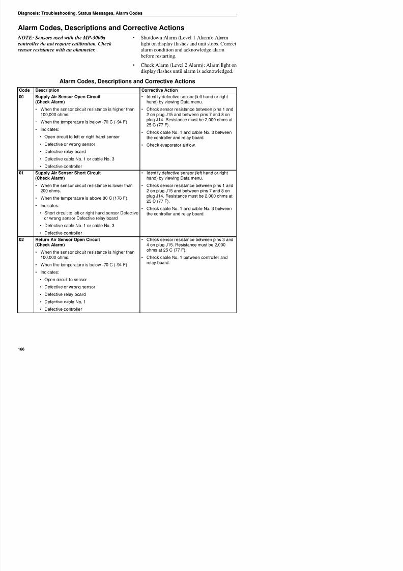
8/12/2019 Termo_King_Magnum_manual.pdf
http://slidepdf.com/reader/full/termokingmagnummanualpdf 166/194
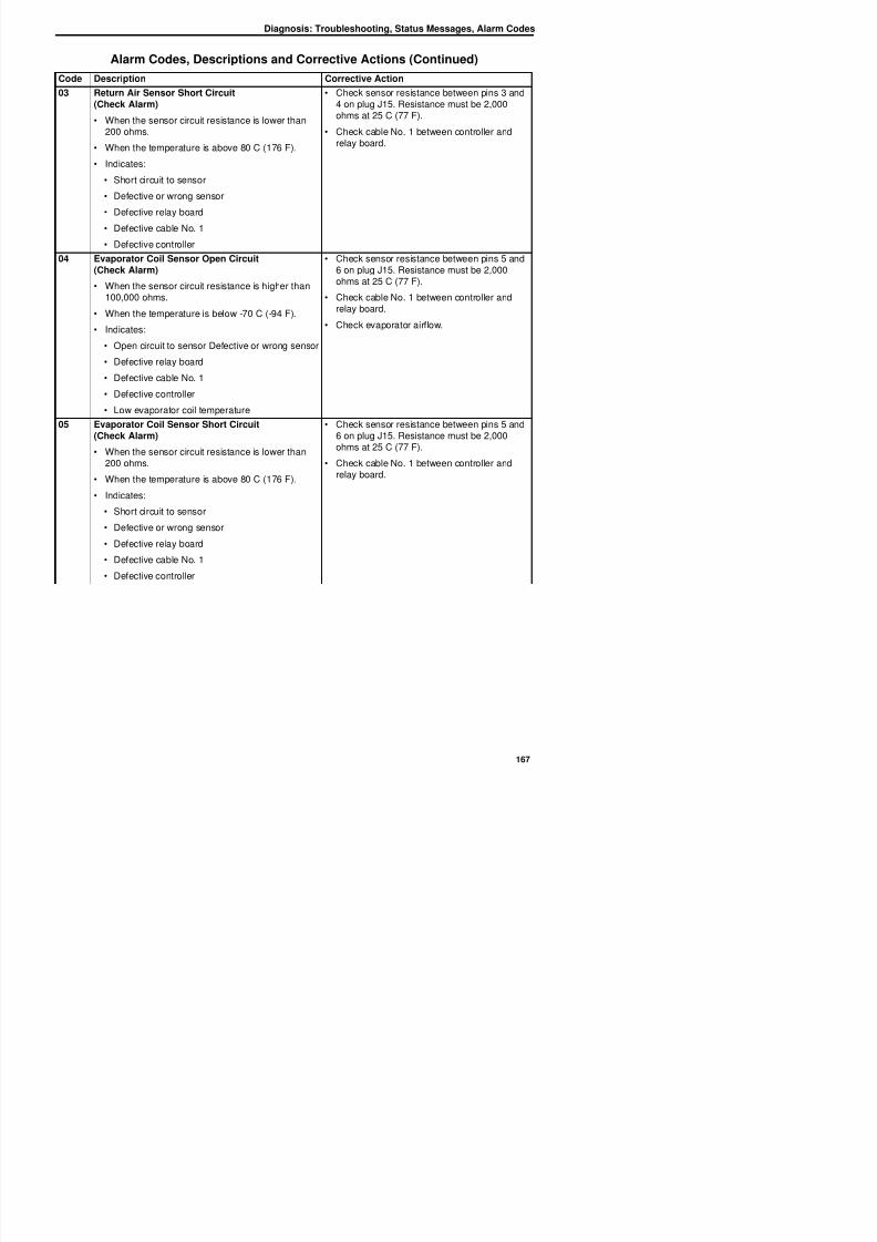
8/12/2019 Termo_King_Magnum_manual.pdf
http://slidepdf.com/reader/full/termokingmagnummanualpdf 167/194
Diagnosis: Troubleshooting, Status Messages, Alarm Codes
06* Compressor Current Too High(Check Alarm)
• Occurs during pretrip (PTI) or function test only.
• Compressor power consumption is 25 percentexpected current draw (above approximately 13amps); or compressor phase current leveldifference of 10 percent or more, depending onambient temperature.
• Indicates:
• Defective Digital Control valve
• Defective compressor
• Check evaporator, condenser and ambientsensor temperatures for correct value(± 5 C [± 9 F]) by viewing Data menu.
• Enter Manual Function Test menu. Start and
check current draw of the followingcomponents separately and together:compressor, compressor 100 percent,condenser fan and evaporator fan (high andlow).
• Check volt and ampere meter.
• Check power supply volts.
Alarm Codes, Descriptions and Corrective Actions (Continued)
Code Description Corrective Action
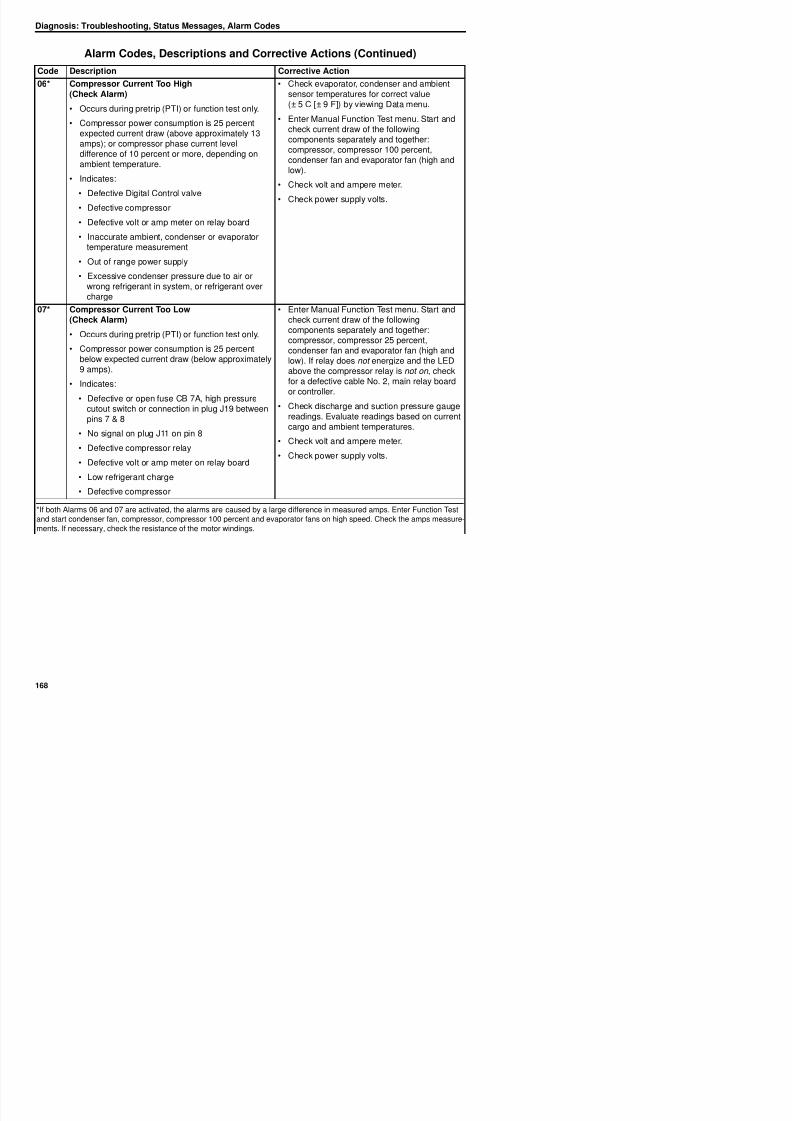
8/12/2019 Termo_King_Magnum_manual.pdf
http://slidepdf.com/reader/full/termokingmagnummanualpdf 168/194
• Defective volt or amp meter on relay board
• Inaccurate ambient, condenser or evaporatortemperature measurement
• Out of range power supply
• Excessive condenser pressure due to air orwrong refrigerant in system, or refrigerant overcharge
07* Compressor Current Too Low(Check Alarm)
• Occurs during pretrip (PTI) or function test only.
• Compressor power consumption is 25 percentbelow expected current draw (below approximately9 amps).
• Indicates:
• Defective or open fuse CB 7A, high pressurecutout switch or connection in plug J19 betweenpins 7 & 8
• No signal on plug J11 on pin 8
• Defective compressor relay
• Defective volt or amp meter on relay board
• Low refrigerant charge
• Defective compressor
• Enter Manual Function Test menu. Start andcheck current draw of the followingcomponents separately and together:compressor, compressor 25 percent,condenser fan and evaporator fan (high andlow). If relay does not energize and the LEDabove the compressor relay is not on , checkfor a defective cable No. 2, main relay board
or controller.• Check discharge and suction pressure gauge
readings. Evaluate readings based on currentcargo and ambient temperatures.
• Check volt and ampere meter.
• Check power supply volts.
*If both Alarms 06 and 07 are acti ated the alarms are ca sed b a large difference in meas red amps Enter F nction Test
Diagnosis: Troubleshooting, Status Messages, Alarm Codes
10* Heater Current Too High(Check Alarm)
• Occurs during pretrip (PTI) or function test only.
• Heater power consumption is 25 percent aboveexpected current draw (above approximately 4.4amps and 5.1 amps, depending on voltage).
• Indicates:
• Incorrect heaters or heater connections
• Defective volt or amp meter on relay board
• Defective heater element
• Enter Manual Function Test and turn heaterson. Check current draw on each phase.Current draw should be about 4.4 amps oneach phase at 400V (5.1 amps at 460V).
• Check heater resistance between H1 and H2,H2 and H3, and H1 and H3. Resistanceshould be about 99 ohms on each leg.
Alarm Codes, Descriptions and Corrective Actions (Continued)
Code Description Corrective Action
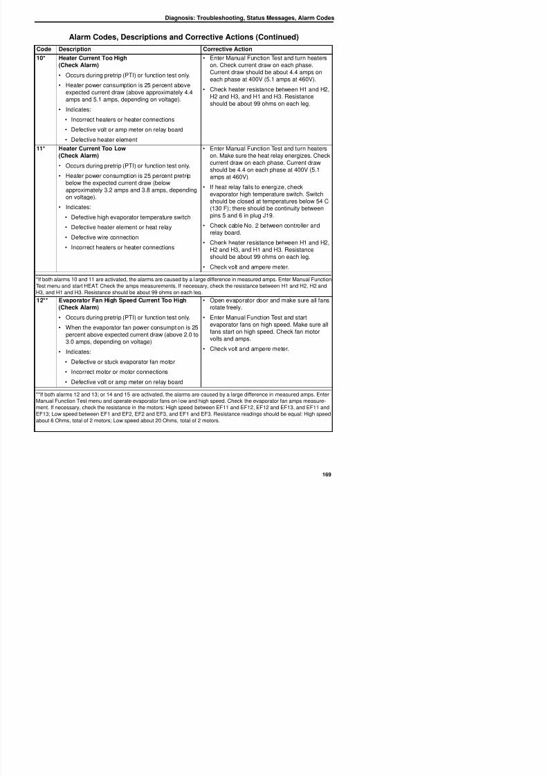
8/12/2019 Termo_King_Magnum_manual.pdf
http://slidepdf.com/reader/full/termokingmagnummanualpdf 169/194
11* Heater Current Too Low(Check Alarm)
• Occurs during pretrip (PTI) or function test only.
• Heater power consumption is 25 percent pretripbelow the expected current draw (belowapproximately 3.2 amps and 3.8 amps, dependingon voltage).
• Indicates:
• Defective high evaporator temperature switch
• Defective heater element or heat relay
• Defective wire connection
• Incorrect heaters or heater connections
• Enter Manual Function Test and turn heaterson. Make sure the heat relay energizes. Checkcurrent draw on each phase. Current drawshould be 4.4 on each phase at 400V (5.1amps at 460V).
• If heat relay fails to energize, checkevaporator high temperature switch. Switchshould be closed at temperatures below 54 C
(130 F); there should be continuity betweenpins 5 and 6 in plug J19.
• Check cable No. 2 between controller andrelay board.
• Check heater resistance between H1 and H2,H2 and H3, and H1 and H3. Resistanceshould be about 99 ohms on each leg.
• Check volt and ampere meter.
*If both alarms 10 and 11 are activated, the alarms are caused by a large difference in measured amps. Enter Manual Function
Test menu and start HEAT. Check the amps measurements. If necessary, check the resistance between H1 and H2, H2 and
H3, and H1 and H3. Resistance should be about 99 ohms on each leg.
12** Evaporator Fan High Speed Current Too High(Check Alarm)
• Occurs during pretrip (PTI) or function test only.
• When the evaporator fan power consumption is 25
percent above expected current draw (above 2.0 to3.0 amps, depending on voltage)
• Indicates:
• Open evaporator door and make sure all fansrotate freely.
• Enter Manual Function Test and startevaporator fans on high speed. Make sure allfans start on high speed. Check fan motorvolts and amps.
• Check volt and ampere meter.
Diagnosis: Troubleshooting, Status Messages, Alarm Codes
13** Evaporator Fan High Speed Current Too Low(Check Alarm)
• Occurs during pretrip (PTI), function test or probetest.
• When the evaporator fan power consumption is 25percent below expected current draw (below 1.6 to2.4 amps, depending on voltage).
• Indicates:
• Defective evaporator fan motor relay
• Defective or open fan motor internal overtemperature protection switch
• Open evaporator door and make sure all fansrotate freely.
• Enter Manual Function Test and startevaporator fans on high speed. Make sure all
fans start on high speed. If a motor does notstart and is very hot, wait 10 minutes forinternal over temperature switch to close.
• Check fan motor volts and amps.
• Check volt and ampere meter.
Alarm Codes, Descriptions and Corrective Actions (Continued)
Code Description Corrective Action
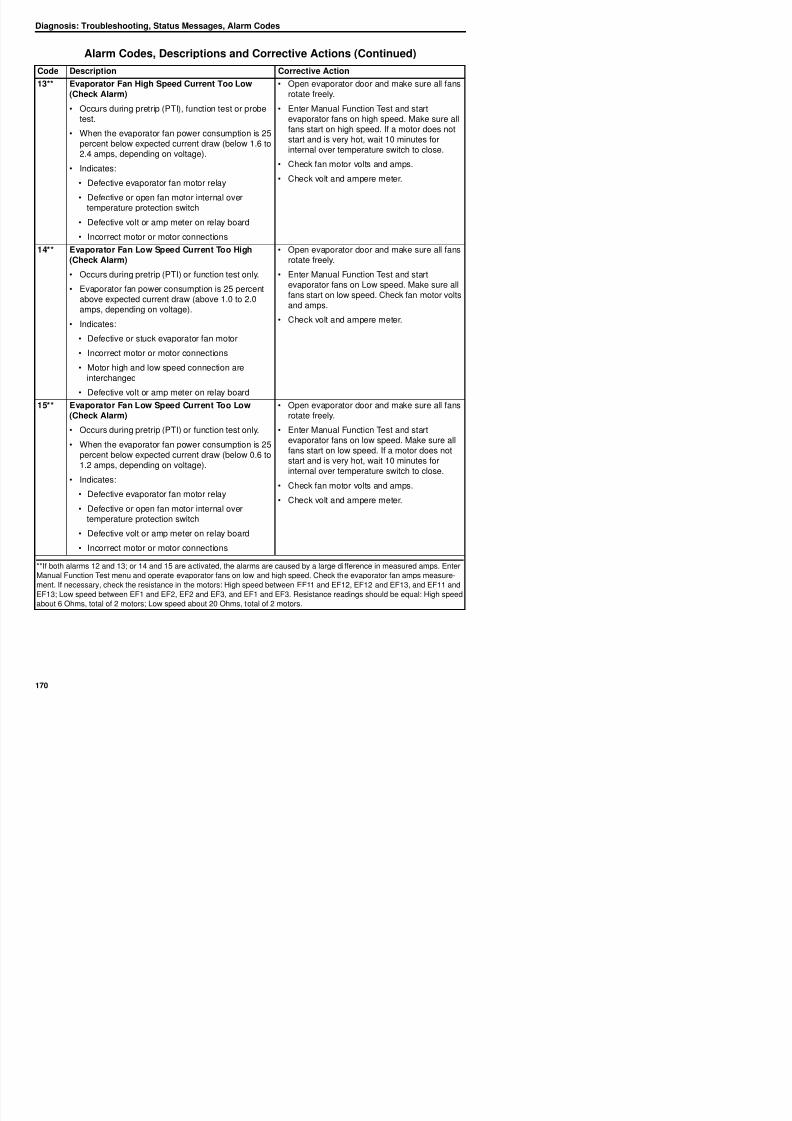
8/12/2019 Termo_King_Magnum_manual.pdf
http://slidepdf.com/reader/full/termokingmagnummanualpdf 170/194
• Defective volt or amp meter on relay board
• Incorrect motor or motor connections
14** Evaporator Fan Low Speed Current Too High(Check Alarm)
• Occurs during pretrip (PTI) or function test only.
• Evaporator fan power consumption is 25 percentabove expected current draw (above 1.0 to 2.0amps, depending on voltage).
• Indicates:
• Defective or stuck evaporator fan motor
• Incorrect motor or motor connections
• Motor high and low speed connection are
interchanged
• Defective volt or amp meter on relay board
• Open evaporator door and make sure all fansrotate freely.
• Enter Manual Function Test and startevaporator fans on Low speed. Make sure allfans start on low speed. Check fan motor volts
and amps.
• Check volt and ampere meter.
15** Evaporator Fan Low Speed Current Too Low(Check Alarm)
• Occurs during pretrip (PTI) or function test only.
• When the evaporator fan power consumption is 25percent below expected current draw (below 0.6 to1.2 amps, depending on voltage).
• Indicates:• Defective evaporator fan motor relay
• Defective or open fan motor internal over
• Open evaporator door and make sure all fansrotate freely.
• Enter Manual Function Test and startevaporator fans on low speed. Make sure allfans start on low speed. If a motor does notstart and is very hot, wait 10 minutes forinternal over temperature switch to close.
• Check fan motor volts and amps.
• Check volt and ampere meter.
Diagnosis: Troubleshooting, Status Messages, Alarm Codes
16* Condenser Fan Current Too High(Check Alarm)
• Occurs during pretrip (PTI) or function test only.
• When the condenser fan power consumption is 25percent above expected current draw (above 1.5 to1.9 amps, depending on voltage).
• Indicates:
• Defective or stuck condenser fan motor
• Defective volt or amp meter on relay board
• Incorrect motor or motor connections
• Enter Manual Function Test and startcondenser fan. Make sure the fan starts.Check fan motor volts and amps.
• Check power supply volts and amps.
• Check volt and ampere meter.
17* C d F C t T L E t M l F ti T t d t t
Alarm Codes, Descriptions and Corrective Actions (Continued)
Code Description Corrective Action
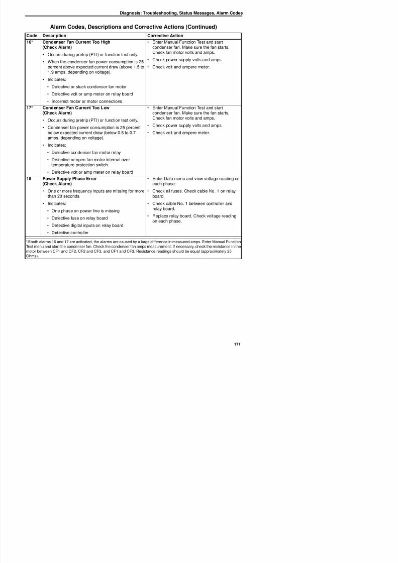
8/12/2019 Termo_King_Magnum_manual.pdf
http://slidepdf.com/reader/full/termokingmagnummanualpdf 171/194
17* Condenser Fan Current Too Low(Check Alarm)
• Occurs during pretrip (PTI) or function test only.
• Condenser fan power consumption is 25 percentbelow expected current draw (below 0.5 to 0.7amps, depending on voltage).
• Indicates:
• Defective condenser fan motor relay• Defective or open fan motor internal over
temperature protection switch
• Defective volt or amp meter on relay board
• Enter Manual Function Test and startcondenser fan. Make sure the fan starts.Check fan motor volts and amps.
• Check power supply volts and amps.
• Check volt and ampere meter.
18 Power Supply Phase Error(Check Alarm)
• One or more frequency inputs are missing for more
than 20 seconds.• Indicates:
• One phase on power line is missing
• Defective fuse on relay board
• Defective digital inputs on relay board
• Defective controller
• Enter Data menu and view voltage reading oneach phase.
• Check all fuses. Check cable No. 1 on relay
board.• Check cable No. 1 between controller and
relay board.
• Replace relay board. Check voltage readingon each phase.
*If both alarms 16 and 17 are activated, the alarms are caused by a large difference in measured amps. Enter Manual FunctionTest menu and start the condenser fan. Check the condenser fan amps measurement. If necessary, check the resistance in the
motor between CF1 and CF2, CF2 and CF3, and CF1 and CF3. Resistance readings should be equal (approximately 25
Ohms)
Diagnosis: Troubleshooting, Status Messages, Alarm Codes
19 Temperature Too Far From Setpoint(Check Alarm)
• After 75 minutes of operation, supply or return airtemperature is not in-range and does not approach
setpoint within preset pull-down rate.
• Indicates:
• Ice or frost on evaporator coil
• Low refrigerant charge
• Air exchange vent open too much
• Container air leakage (doors open)
• Press SUP/RET key to check supply and returnair sensor temperatures. Comparetemperatures to evaluate unit cooling capacityand performance.
• Temperature difference should be 4 C to 6 C(39 F - 43 F).
• Open evaporator door. Inspect coil for ice orfrost and initiate manual defrost if necessary.
• Check refrigerant charge
NOTE: This alarm can be activated if the
supply or return air temperature varies,
if th t t d
Alarm Codes, Descriptions and Corrective Actions (Continued)
Code Description Corrective Action
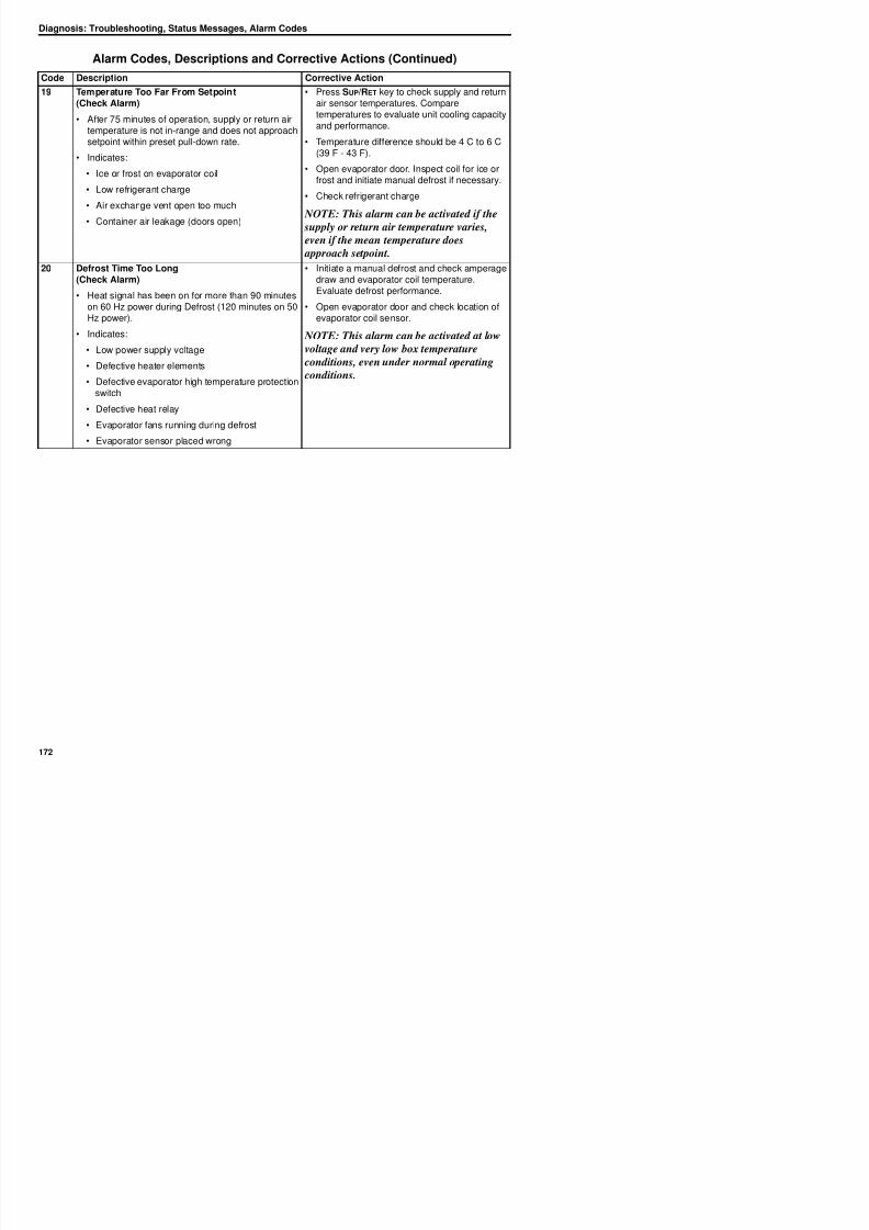
8/12/2019 Termo_King_Magnum_manual.pdf
http://slidepdf.com/reader/full/termokingmagnummanualpdf 172/194
even if the mean temperature does approach setpoint.
20 Defrost Time Too Long(Check Alarm)
• Heat signal has been on for more than 90 minuteson 60 Hz power during Defrost (120 minutes on 50Hz power).
• Indicates:• Low power supply voltage
• Defective heater elements
• Defective evaporator high temperature protectionswitch
• Defective heat relay
• Evaporator fans running during defrost
• Evaporator sensor placed wrong
• Initiate a manual defrost and check amperagedraw and evaporator coil temperature.Evaluate defrost performance.
• Open evaporator door and check location ofevaporator coil sensor.
NOTE: This alarm can be activated at lowvoltage and very low box temperature
conditions, even under normal operating
conditions.
Diagnosis: Troubleshooting, Status Messages, Alarm Codes
22 Capacity Test 1 Error(Check Alarm)
• Occurs during pretrip (PTI) test only.
• Difference between supply and return airtemperature is too small with high speedevaporator fans (less than approximately 4.5 C [8F]).
• When the return air temperature does not reach-18 C (0 F) within preset time.
• Indicates:
• Incorrect location of supply or return air sensor
Ai l k t l bl
• Enter Manual Function Test and startevaporator fans on high speed. Then selectSensor Checks test and operate fans 2 to 5minutes. Check supply, return and evaporator
coil (defrost) sensor temperatures. Sensorreadings should be the same (evaporator coilmay be 0.5 C [1.0 F] lower due to fan motorheat).
NOTE: This sensor check does not detect
air leakage around the sensor cables.• Open evaporator door and inspect evaporator
fan rotation. Make sure fans are rotating
correctly on low speed
Alarm Codes, Descriptions and Corrective Actions (Continued)
Code Description Corrective Action
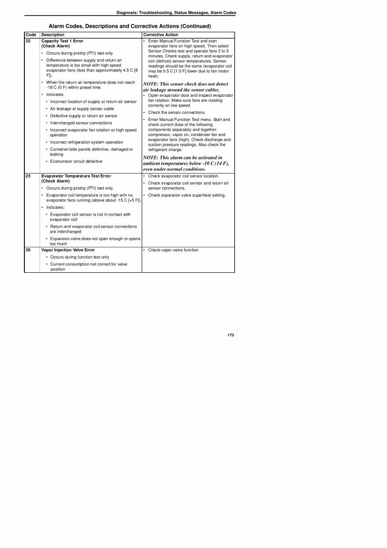
8/12/2019 Termo_King_Magnum_manual.pdf
http://slidepdf.com/reader/full/termokingmagnummanualpdf 173/194
• Air leakage at supply sensor cable
• Defective supply or return air sensor
• Interchanged sensor connections
• Incorrect evaporator fan rotation or high speedoperation
• Incorrect refrigeration system operation
• Container/side panels defective, damaged orleaking
• Economizer circuit defective
correctly on low speed.• Check the sensor connections.
• Enter Manual Function Test menu. Start andcheck current draw of the followingcomponents separately and together:compressor, vapor on, condenser fan andevaporator fans (high). Check discharge andsuction pressure readings. Also check the
refrigerant charge.
NOTE: This alarm can be activated in
ambient temperatures below -10 C (14 F),
even under normal conditions.
25 Evaporator Temperature Test Error(Check Alarm)
• Occurs during pretrip (PTI) test only.
• Evaporator coil temperature is too high with noevaporator fans running (above about -15 C [+5 F]).
• Indicates:
• Evaporator coil sensor is not in contact withevaporator coil
• Return and evaporator coil sensor connectionsare interchanged
• Expansion valve does not open enough or openstoo much
• Check evaporator coil sensor location.
• Check evaporator coil sensor and return airsensor connections.
• Check expansion valve superheat setting.
26 V I j i V l E Ch k l f i
Diagnosis: Troubleshooting, Status Messages, Alarm Codes
27 Heat Capacity Test Error(Check Alarm)
• Occurs during pretrip (PTI) test only.
• Difference between supply and return airtemperature is too small with high speedevaporator fans (less than 0.4 C [0.7 F]).
• Indicates:
• Incorrect location of supply or return air sensor
• Air leakage at supply, return or evaporator coilsensor cable
• Defective supply or return air sensor
• Enter Manual Function Test and startevaporator fans on high speed. Then selectSensor Checks test and operate fans 2 to 5minutes. Check supply, return and evaporator
coil (defrost) sensor temperatures. Sensorreadings should be the same (evaporator coilmay be 0.5 C [1.0 F] lower due to fan motorheat).
NOTE: This sensor check does not detect
air leakage around the sensor cables.• Open evaporator door and inspect evaporator
fan rotation. Make sure fans are rotating
correctly on high speed
Alarm Codes, Descriptions and Corrective Actions (Continued)
Code Description Corrective Action
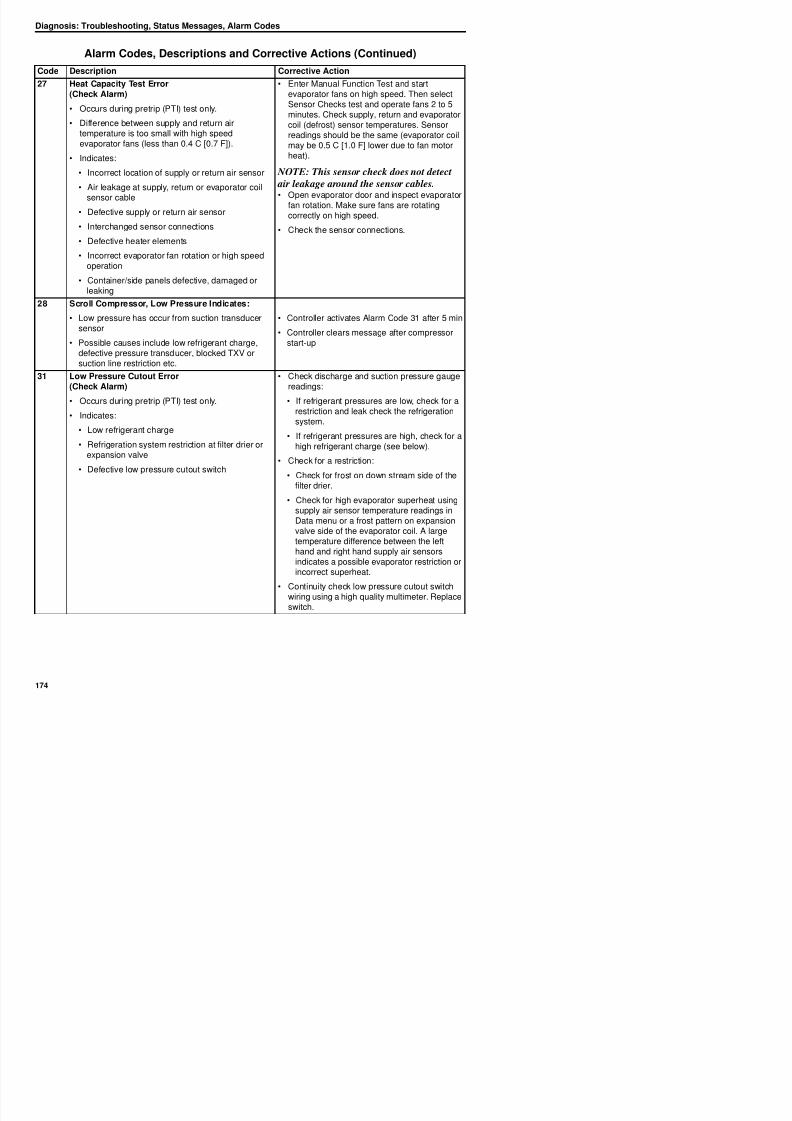
8/12/2019 Termo_King_Magnum_manual.pdf
http://slidepdf.com/reader/full/termokingmagnummanualpdf 174/194
• Interchanged sensor connections
• Defective heater elements
• Incorrect evaporator fan rotation or high speedoperation
• Container/side panels defective, damaged orleaking
correctly on high speed.• Check the sensor connections.
28 Scroll Compressor, Low Pressure Indicates:• Low pressure has occur from suction transducer
sensor
• Possible causes include low refrigerant charge,defective pressure transducer, blocked TXV orsuction line restriction etc.
• Controller activates Alarm Code 31 after 5 min
• Controller clears message after compressorstart-up
31 Low Pressure Cutout Error(Check Alarm)
• Occurs during pretrip (PTI) test only.
• Indicates:
• Low refrigerant charge
• Refrigeration system restriction at filter drier orexpansion valve
• Defective low pressure cutout switch
• Check discharge and suction pressure gaugereadings:
• If refrigerant pressures are low, check for arestriction and leak check the refrigerationsystem.
• If refrigerant pressures are high, check for ahigh refrigerant charge (see below).
• Check for a restriction:
• Check for frost on down stream side of the
filter drier.
• Check for high evaporator superheat usingl i t t di i
Diagnosis: Troubleshooting, Status Messages, Alarm Codes
32 Condenser Temperature Sensor Open Circuit(Check Alarm)
• When the sensor circuit resistance is higher than100,000 ohms.
• When the temperature is below -70 C (-94 F).
• Indicates:
• Open circuit to sensor
• Defective or wrong sensor
• Defective relay board
• Defective cable No. 1
• Defective controller
• Check sensor resistance between pins 7 and8 on plug J15. Resistance must be 2,000ohms at 25 C (77 F).
• Check cable No. 1 between controller and
relay board.
Alarm Codes, Descriptions and Corrective Actions (Continued)
Code Description Corrective Action
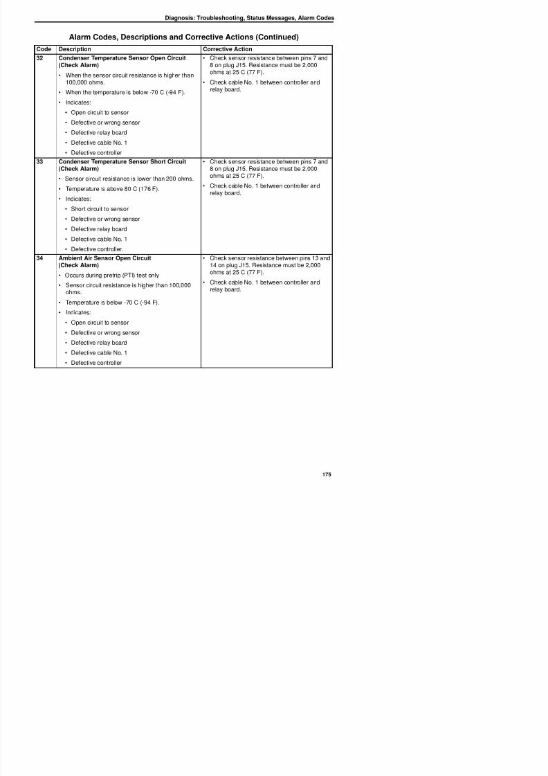
8/12/2019 Termo_King_Magnum_manual.pdf
http://slidepdf.com/reader/full/termokingmagnummanualpdf 175/194
Defective controller
33 Condenser Temperature Sensor Short Circuit(Check Alarm)
• Sensor circuit resistance is lower than 200 ohms.
• Temperature is above 80 C (176 F).
• Indicates:
• Short circuit to sensor
• Defective or wrong sensor
• Defective relay board
• Defective cable No. 1
• Defective controller.
• Check sensor resistance between pins 7 and8 on plug J15. Resistance must be 2,000ohms at 25 C (77 F).
• Check cable No. 1 between controller andrelay board.
34 Ambient Air Sensor Open Circuit(Check Alarm)
• Occurs during pretrip (PTI) test only
• Sensor circuit resistance is higher than 100,000ohms.
• Temperature is below -70 C (-94 F).
• Indicates:
• Open circuit to sensor
• Defective or wrong sensor• Defective relay board
Defective cable No 1
• Check sensor resistance between pins 13 and14 on plug J15. Resistance must be 2,000
ohms at 25 C (77 F).• Check cable No. 1 between controller and
relay board.
Diagnosis: Troubleshooting, Status Messages, Alarm Codes
35 Ambient Air Sensor Short Circuit(Check Alarm)
• Occurs during pretrip (PTI) test only.
• Sensor circuit resistance is lower than 200 ohms.
• Temperature is above 80 C (176 F).
• Indicates:
• Short circuit to sensor
• Defective or wrong sensor
• Defective relay board
• Defective cable No. 1
• Defective controller
• Check sensor resistance between pins 13 and14 on plug J15. Resistance must be 2,000ohms at 25 C (77 F).
• Check cable No. 1 between controller and
relay board.
Alarm Codes, Descriptions and Corrective Actions (Continued)
Code Description Corrective Action
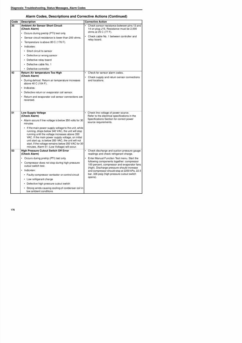
8/12/2019 Termo_King_Magnum_manual.pdf
http://slidepdf.com/reader/full/termokingmagnummanualpdf 176/194
• Defective controller
43 Return Air temperature Too High(Check Alarm)
• During defrost: Return air temperature increasesabove 40 C (104 F).
• Indicates:
• Defective return or evaporator coil sensor.
• Return and evaporator coil sensor connections arereversed.
• Check for sensor alarm codes.
• Check supply and return sensor connectionsand locations.
51 Low Supply Voltage(Check Alarm)
• Alarm occurs if line voltage is below 350 volts for 30minutes
• If the main power supply voltage to the unit, whilerunning, drops below 340 VAC, the unit will stoprunning until the voltage increases above 350VAC. If the main power supply voltage, on initialunit start up, is below 350 VAC, the unit will notstart. If the voltage remains below 350 VAC for 30minutes, Alarm 51 (Low Voltage) will occur.
• Check line voltage of power source.Refer to the electrical specifications in theSpecifications Section for correct power
source requirements.
53 High Pressure Cutout Switch Off Error(Check Alarm)
• Check discharge and suction pressure gaugereadings and check refrigerant charge.
Diagnosis: Troubleshooting, Status Messages, Alarm Codes
54 High Pressure Cutout Switch On Error(Check Alarm)
• Occurs during pretrip (PTI) test only.
• Compressor does not start within normal timeduring high pressure cutout switch test.
• Indicates:
• High pressure cutout switch did not respond topressure change within 5 seconds
• Air in refrigeration system
• Defective high pressure cutout switch
• Check discharge and suction pressure gaugereadings.
• Enter Manual Function Test menu. Start thefollowing components together: compressor
100 percent, compressor and evaporator fans(high). Discharge pressure should increaseand compressor should stop at 2250 kPa, 22.5bar, 326 psig (high pressure cutout switchopens). Then start condenser fan. Dischargepressure must drop quickly (10 to 20 seconds)to 1550 kPa, 15.5 bar, 225 psig andcompressor should start (switch closes)
56 Compressor Temperature Too High(Shutdown Alarm) • Operate unit on Cool and check discharge andsuction pressure gauge readings
Alarm Codes, Descriptions and Corrective Actions (Continued)
Code Description Corrective Action
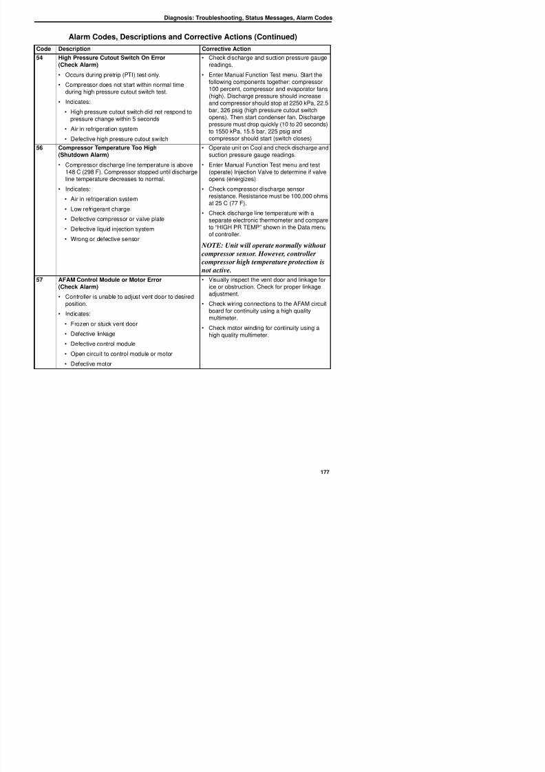
8/12/2019 Termo_King_Magnum_manual.pdf
http://slidepdf.com/reader/full/termokingmagnummanualpdf 177/194
p p g(Shutdown Alarm)
• Compressor discharge line temperature is above148 C (298 F). Compressor stopped until dischargeline temperature decreases to normal.
• Indicates:
• Air in refrigeration system
• Low refrigerant charge• Defective compressor or valve plate
• Defective liquid injection system
• Wrong or defective sensor
p gsuction pressure gauge readings.
• Enter Manual Function Test menu and test(operate) Injection Valve to determine if valveopens (energizes).
• Check compressor discharge sensorresistance. Resistance must be 100,000 ohmsat 25 C (77 F).
• Check discharge line temperature with aseparate electronic thermometer and compareto “HIGH PR TEMP” shown in the Data menuof controller.
NOTE: Unit will operate normally without
compressor sensor. However, controller
compressor high temperature protection is
not active.57 AFAM Control Module or Motor Error
(Check Alarm)
• Controller is unable to adjust vent door to desiredposition.
• Indicates:
• Frozen or stuck vent door
• Defective linkage• Defective control module
• Visually inspect the vent door and linkage forice or obstruction. Check for proper linkageadjustment.
• Check wiring connections to the AFAM circuitboard for continuity using a high qualitymultimeter.
• Check motor winding for continuity using a
high quality multimeter.
Diagnosis: Troubleshooting, Status Messages, Alarm Codes
58 Phase Sensor Error(Check Alarm)
• Occurs during pretrip (PTI) or function test only.
• During Phase Sensor Test, amperage differencebetween correct and wrong condenser fan rotationis more than 0.2 amps.
• Indicates:
• Defective phase relay
• Defective relay board
• Defective relay board cable No. 2
• Start a Function Test. During step F1.05,check whether the phase relays on relayboard receive a signal (LED energizes). Verifythat the relays respond and shift to reverse
phase.
59 Delta Current Error(Check Alarm) • Enter Manual Function Test menu and test(operate) each 3-phase component to locate
Alarm Codes, Descriptions and Corrective Actions (Continued)
Code Description Corrective Action
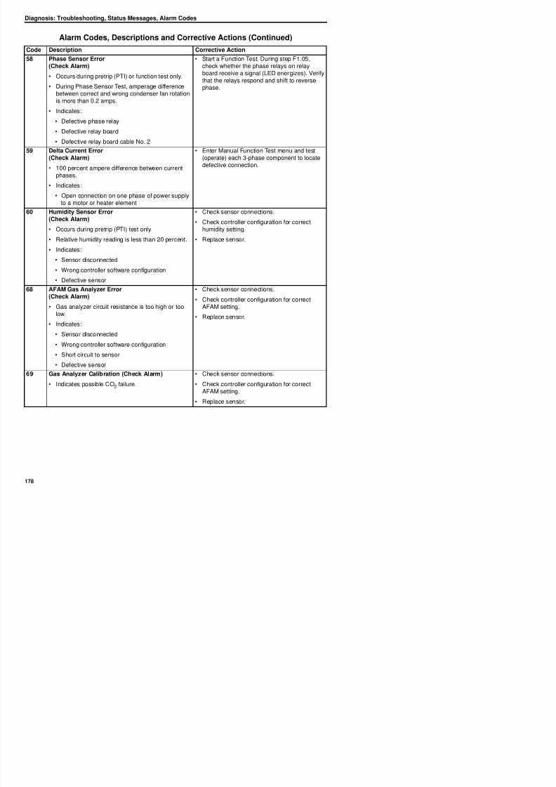
8/12/2019 Termo_King_Magnum_manual.pdf
http://slidepdf.com/reader/full/termokingmagnummanualpdf 178/194
(Check Alarm)
• 100 percent ampere difference between currentphases.
• Indicates:
• Open connection on one phase of power supplyto a motor or heater element
(operate) each 3 phase component to locatedefective connection.
60 Humidity Sensor Error(Check Alarm)
• Occurs during pretrip (PTI) test only.
• Relative humidity reading is less than 20 percent.
• Indicates:
• Sensor disconnected
• Wrong controller software configuration
• Defective sensor
• Check sensor connections.
• Check controller configuration for correcthumidity setting.
• Replace sensor.
68 AFAM Gas Analyzer Error(Check Alarm)
• Gas analyzer circuit resistance is too high or toolow.
• Indicates:
• Sensor disconnected
• Wrong controller software configuration
• Short circuit to sensor
• Check sensor connections.
• Check controller configuration for correctAFAM setting.
• Replace sensor.
Diagnosis: Troubleshooting, Status Messages, Alarm Codes
97 Compressor Sensor Open Circuit(Check Alarm)
• When the sensor circuit resistance is higher than10,000,000 ohms.
• Temperature is below -30 C (-22 F).
• Indicates:
• Open circuit to sensor
• Defective or wrong sensor
• Defective relay board
• Defective cable No. 1
• Defective controller
• Check sensor resistance between pins 9 and10 on plug J15. Resistance must be 100,000ohms at 25 C (77 F).
• Check cable No. 1 between controller and
relay board.
NOTE: Unit will operate normally without
compressor sensor. However, controller
compressor high temperature protection is
not active.
Alarm Codes, Descriptions and Corrective Actions (Continued)
Code Description Corrective Action
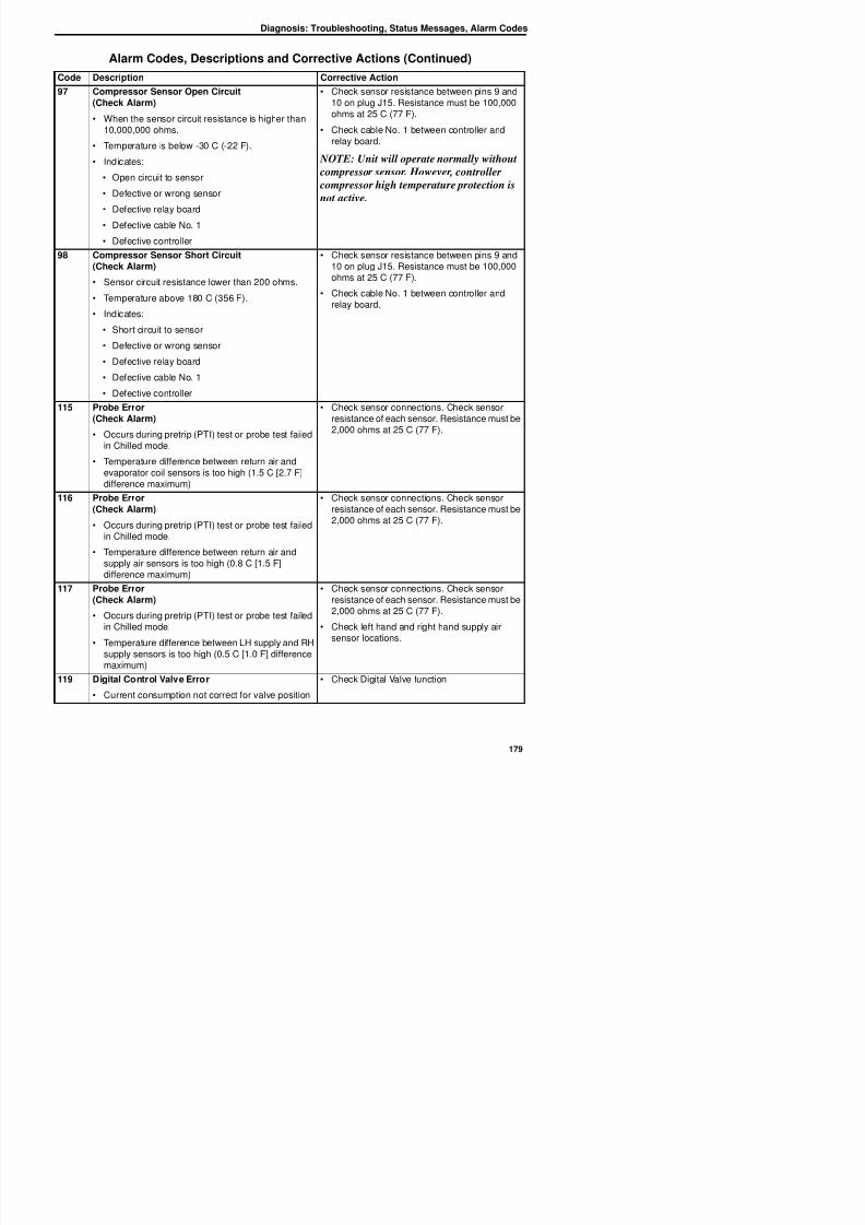
8/12/2019 Termo_King_Magnum_manual.pdf
http://slidepdf.com/reader/full/termokingmagnummanualpdf 179/194
98 Compressor Sensor Short Circuit(Check Alarm)
• Sensor circuit resistance lower than 200 ohms.
• Temperature above 180 C (356 F).
• Indicates:
• Short circuit to sensor
• Defective or wrong sensor
• Defective relay board
• Defective cable No. 1
• Defective controller
• Check sensor resistance between pins 9 and10 on plug J15. Resistance must be 100,000ohms at 25 C (77 F).
• Check cable No. 1 between controller andrelay board.
115 Probe Error(Check Alarm)
• Occurs during pretrip (PTI) test or probe test failedin Chilled mode.
• Temperature difference between return air andevaporator coil sensors is too high (1.5 C [2.7 F]difference maximum)
• Check sensor connections. Check sensorresistance of each sensor. Resistance must be
2,000 ohms at 25 C (77 F).
116 Probe Error(Check Alarm)
• Occurs during pretrip (PTI) test or probe test failedin Chilled mode.
• Temperature difference between return air and
• Check sensor connections. Check sensorresistance of each sensor. Resistance must be2,000 ohms at 25 C (77 F).
Diagnosis: Troubleshooting, Status Messages, Alarm Codes
120 Suction Pressure Sensor
• Indicate a problem exists with this sensor or itswiring. The sensor is reading out of the range, orappears to be open or shorted
PTI Test
• Reading did not decease by 0.15 bar (2.175 psi)between compressor on and off
Check wiring at J14 and J15 to be correct andconnected
Check J14 and J15 plugs are plugged into MRB
Check voltage at J15 pin12 to be 0.5 – 4.5 volts
Check cable No 1 and cable No. 3 between thecontroller and MRB
121 Discharge Pressure SensorIndicate a problem exists with this sensor or its Check wiring at J14 and J15 to be correct and
Alarm Codes, Descriptions and Corrective Actions (Continued)
Code Description Corrective Action
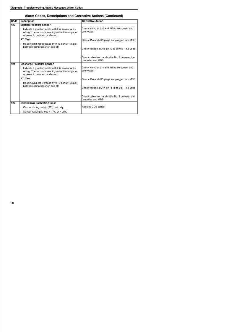
8/12/2019 Termo_King_Magnum_manual.pdf
http://slidepdf.com/reader/full/termokingmagnummanualpdf 180/194
• Indicate a problem exists with this sensor or itswiring. The sensor is reading out of the range, orappears to be open or shorted
PTI Test
• Reading did not increase by 0.15 bar (2.175 psi)between compressor on and off
Check wiring at J14 and J15 to be correct andconnected
Check J14 and J15 plugs are plugged into MRB
Check voltage at J14 pin11 to be 0.5 – 4.5 volts
Check cable No 1 and cable No. 3 between thecontroller and MRB
122 CO2 Sensor Calibration Error
• Occurs during pretrip (PTI) test only
• Sensor reading is less < 17% or > 25%
Replace CO2 sensor
Index
Symbols 16, 20, 29
AAdvanced 35Advanced Fresh Air Management (AFAM) 35
Advanced Fresh Air Management Plus (AFAM+) 35,85, 89
AFAMAFAM Option, Configuration Menu 66Description 35Setting 53
AFAM+ 89Description 35
Operation 85Setting 53
Digital Control Valve, Operating Theory 112Discharge Gas Temperature Sensor
Description 125Discharge Temperature Sensor
Replacement 125Installation 142
Isolation 130Nameplate Location 16Oil Acid Test 130Scroll 30Vapor Injection 105
Condenser CoilCleaning 151Drawing 38Installation 143Removal 143T t 57
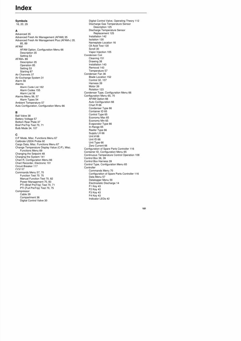
8/12/2019 Termo_King_Magnum_manual.pdf
http://slidepdf.com/reader/full/termokingmagnummanualpdf 181/194
Starting 87Air Channels 37Air Exchange System 31Alarm 56Alarms
Alarm Code List 162Alarm Codes 155
Alarm List 56Alarms Menu 56, 57
Alarm Types 54Ambient Temperature 57Auto Configuration, Configuration Menu 66
BBall Valve 38Battery Voltage 57Bottom Rear Plate 37Brief PreTrip Test 70, 71Bulb Mode 34, 107
CC/F Mode, Misc. Functions Menu 67Calibrate USDA Probe 60Cargo Data, Misc. Functions Menu 67
Change Temperature Display Value (C/F), Misc.Functions Menu 69
Changing the Setpoint 48
Temperature 57Condenser Fan 36
Blade Location 152Control 32, 107Harness 39Motor 39Rotation 123
Condenser Type, Configuration Menu 66Configuration Menu 65, 70AFAM Option 66Auto Configuration 66Chart R 66Condenser Type 66Container ID 65Control Type 65Economy Max 65
Economy Min 65Evaporator Type 66In-Range 65Reefer Type 66Supply LH 66Unit # 66Unit ID 66Unit Type 66Zero Current 66
Configuration of Spare Parts Controller 116Container ID, Configuration Menu 65Continuous Temperature Control Operation 108
Index
Input and Output Signals 47Keypad 41, 43Maintenance 115Menu Scrolling Keys 43Message Display 41, 42Misc. Functions Menu 67MP-3000a 30Replacement 115RMM State Menu 58Setpoint Menu
Controller MenuSetpoint Menu 50
Software Selection 115Special Function Keys 41, 42Temperature Status Display 41Text Input 43
Text Input Example 44Controller Menu
Voltage 1 (Main Power Supply) 57Voltage 2 57Voltage 3 57Voltage Average 57
Data Recording, Operating Theory 113Datalogger Menu 59
Calibrate USDA Probe 60Inspect Event Log 60, 64Inspect Temp Log 59Set Log Time 63Set Trip Start 62
Date Time, Misc. Functions Menu 67Defrost Drains Cleaning 151Defrost Termination 39Defrost, Operating Theory 111Dehumidify Mode 107
Dehydrator 38Diagnosis 155
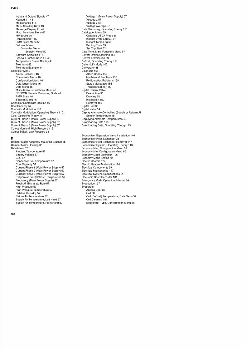
8/12/2019 Termo_King_Magnum_manual.pdf
http://slidepdf.com/reader/full/termokingmagnummanualpdf 182/194
Alarm List Menu 46Commands Menu 46Configuration Menu 46Data logger Menu 46Data Menu 46Miscellaneous Functions Menu 46REFCON Remote Monitoring State 46
RMM State 46Setpoint Menu 46
Controller Nameplate location 16Cool Capacity 57Cool with Modulation 110Cool with Modulation, Operating Theory 110Cool, Operating Theory 111Current Phase 1 (Main Power Supply) 57Current Phase 2 (Main Power Supply) 57Current Phase 3 (Main Power Supply) 57Cutout Manifold, High Pressure 119Cutout Switch, Low Pressure 38
DDamper Motor Assembly Mounting Bracket 35Damper Motor Housing 35Data Menu 57
Ambient Temperature 57Battery Voltage 57CO2 57
gAlarm Codes 155Mechanical Problems 156Refrigeration Problems 159Status Messages 155Troubleshooting 155
Digital Control ValveDescription 30
Drawing 38Installation 150Removal 150
Digital Port 30Digital Valve 39Display Alternate Controlling (Supply or Return) Air
Sensor Temperature 48Displaying Alternate Temperatures 49Downloading Data 113Downloading Data, Operating Theory 113
EEconomizer Expansion Valve Installation 146Economizer Heat Exchanger 38Economizer Heat Exchanger Removal 147Economizer System, Operating Theory 113Economy Max, Configuration Menu 65
Economy Min, Configuration Menu 65Economy Mode Operation 106Economy Mode Setting 52
Index
Fan 32Fan Control 106Fan Harness 39Fan Location 152Fan Motor 39Fan Rotation 123Grille 37Overheat Switch 117
Event Log, Inspect 60Expansion Valve 38Expansion Valve (Economizer) 38
FFeatures & Options 29Filter Drier Installation 144Filter Drier Removal 144
First Aid 14Fittings 129
In-line Filter Installation 144In-line Filter Removal 144In-line Filter Replacement 144In-Range, Configuration Menu 65Interface Board 35Intermediate Suction Port 30
LLeak Detection 129Leak Test the Refrigeration System 134Linkage Assembly 35Low Pressure Cutout Switch 38Low Voltage Safety Instructions 14LPCO Switch 39
M
MagnumBack View 37
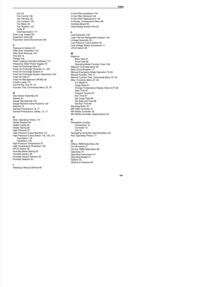
8/12/2019 Termo_King_Magnum_manual.pdf
http://slidepdf.com/reader/full/termokingmagnummanualpdf 183/194
gFlash Loading Controller Software 115Frequency (Main Power Supply) 57Fresh Air Exchange Rate 57Fresh Air Exchange Recorder 31, 100Fresh Air Exchange System 31Fresh Air Exchange System Adjustment 152Fresh Air Inlet 37
Fresh Air Management (AFAM) 35Frozen Loads 110Full PreTrip Test 70, 75Function Test, Commands Menu 70, 79
GGas Sensor Assembly 35Gasket 35
Gauge Manifold Set 130Gauge Manifold Valve Positions 130General 13General Precautions 13, 17General Precautions, Safety, 13, 17
HHeat, Operating Theory 110Heater Bracket 39
Heater Leads 39Heater Spring 39High Pressure 57
Back View 37Front View 36Operating Mode Function Chart 109
Magnum Unit Description 29Main Circuit Breaker 117Manual Emergency Mode Operation 79, 84Manual Function Test 71Manual Function Test, Commands Menu 70, 82Misc. Functions Menu 67, 84
C/F Mode 67Cargo Data 67Change Temperature Display Value (C/F) 69Date Time 67Program Version 67Run Time 67Set Cargo Data 69
Set Date and Time 68Set Run Time 68Mounting Bolts 151MP-3000 Controller 31MP-3000a Controller 30MP-3000a Controller, Specifications 24
NNameplate Location
Compressor 16Controller 16Unit 16
Index
PPhysical Specifications, Specifications 26Power Cable 39Power Cable Bracket 39Power Limit Management 105Power Limit Mode 106Power Management, Commands Menu 70, 83Power Phase Reversal 126Power Plug 39Precautions, General 13, 17Pressure Gauge Options 33Pressure Rise Test 140Pressurized Nitrogen 134PreTrip Test 70Probe Test 107Program Version, Misc. Functions Menu 67
PTIBrief PreTrip) Test, Commands Menu 70, 71
Sensor Kit 39Sequence Of Operation 47, 108Serial Number Locations 16Service 17Service Guide 17Servicing The Unit 151Set Cargo Data, Misc. Functions Menu 69Set Date and Time, Misc. Functions Menu 68Set Run Time, Misc. Functions Menu 68Setpoint Menu 50
AFAM Setting 53AFAM+ Setting 53Change the Bulb Mode Setting 51Change the Economy Mode Setting 52Change the Humidity Mode Setting 52Change the Humidity Setpoint 53
Change the Setpoint Temperature 51Sight Glass 32S l id V l 39
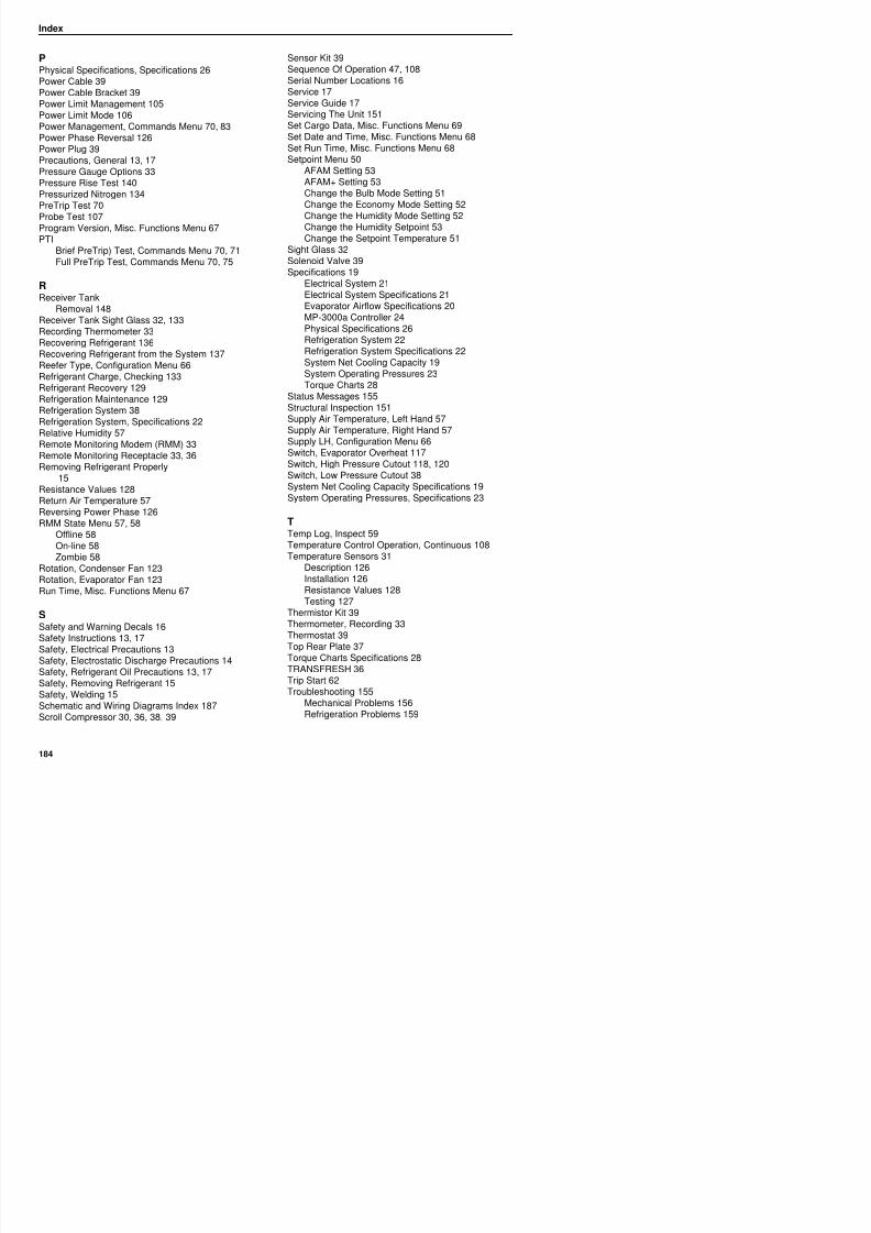
8/12/2019 Termo_King_Magnum_manual.pdf
http://slidepdf.com/reader/full/termokingmagnummanualpdf 184/194
Full PreTrip Test, Commands Menu 70, 75
RReceiver Tank
Removal 148Receiver Tank Sight Glass 32, 133Recording Thermometer 33
Recovering Refrigerant 136Recovering Refrigerant from the System 137Reefer Type, Configuration Menu 66Refrigerant Charge, Checking 133Refrigerant Recovery 129Refrigeration Maintenance 129Refrigeration System 38Refrigeration System, Specifications 22
Relative Humidity 57Remote Monitoring Modem (RMM) 33Remote Monitoring Receptacle 33, 36Removing Refrigerant Properly
15Resistance Values 128Return Air Temperature 57Reversing Power Phase 126RMM State Menu 57, 58
Offline 58On-line 58Zombie 58
Solenoid Valve 39Specifications 19
Electrical System 21Electrical System Specifications 21Evaporator Airflow Specifications 20MP-3000a Controller 24Physical Specifications 26
Refrigeration System 22Refrigeration System Specifications 22System Net Cooling Capacity 19System Operating Pressures 23Torque Charts 28
Status Messages 155Structural Inspection 151Supply Air Temperature, Left Hand 57Supply Air Temperature, Right Hand 57
Supply LH, Configuration Menu 66Switch, Evaporator Overheat 117Switch, High Pressure Cutout 118, 120Switch, Low Pressure Cutout 38System Net Cooling Capacity Specifications 19System Operating Pressures, Specifications 23
T
Temp Log, Inspect 59Temperature Control Operation, Continuous 108Temperature Sensors 31
Index
UUnit
Decals, Identifying 16Description 29Description, Features & Options 29Inspection 151Nameplate Location 16On/Off Switch 47Protection Devices 117Unit #, Configuration Menu 66Unit ID, Configuration Menu 66Unit Type, Configuration Menu 66
Unit Description 29Unit Description, Features & Options 29Unit Features & Options 29Unit Options 33
Unit Start-up 47USDA Probe, Calibrate 60USDA R t l P l 36 37 39
WWater Cooled Condenser Tank 38Water Pressure Switch 34Water-Cooled Condenser
Description 34Water-Cooled Condenser Tank
Removal 148Welding, Safety 15Wiring and Schematic Diagrams Index 187
ZZero Current, Configuration Menu 66Zombie, RMM State Menu 58
8/12/2019 Termo_King_Magnum_manual.pdf
http://slidepdf.com/reader/full/termokingmagnummanualpdf 185/194
USDA Receptacle Panel 36, 37, 39
VVacuum Pump 129Vapor Injection 105Vapor Injection Solenoid Valve 38Vapor Injection Valve Installation 149
Vapor Injection Valve Removal 149Vent Door Assembly 35, 86Voltage 1 (Main Power Supply) 57Voltage 2 57Voltage 3 57Voltage Average 57
Index

8/12/2019 Termo_King_Magnum_manual.pdf
http://slidepdf.com/reader/full/termokingmagnummanualpdf 186/194
Wiring and Schematic Diagrams Index
Dwg No. Drawing Title Page
1E09120 Wiring Schematic 189
1E09121 Wiring Diagram 190-191
MAGNUM Refrigeration System Components 192
MP-3000a Menu Flow Diagram 194
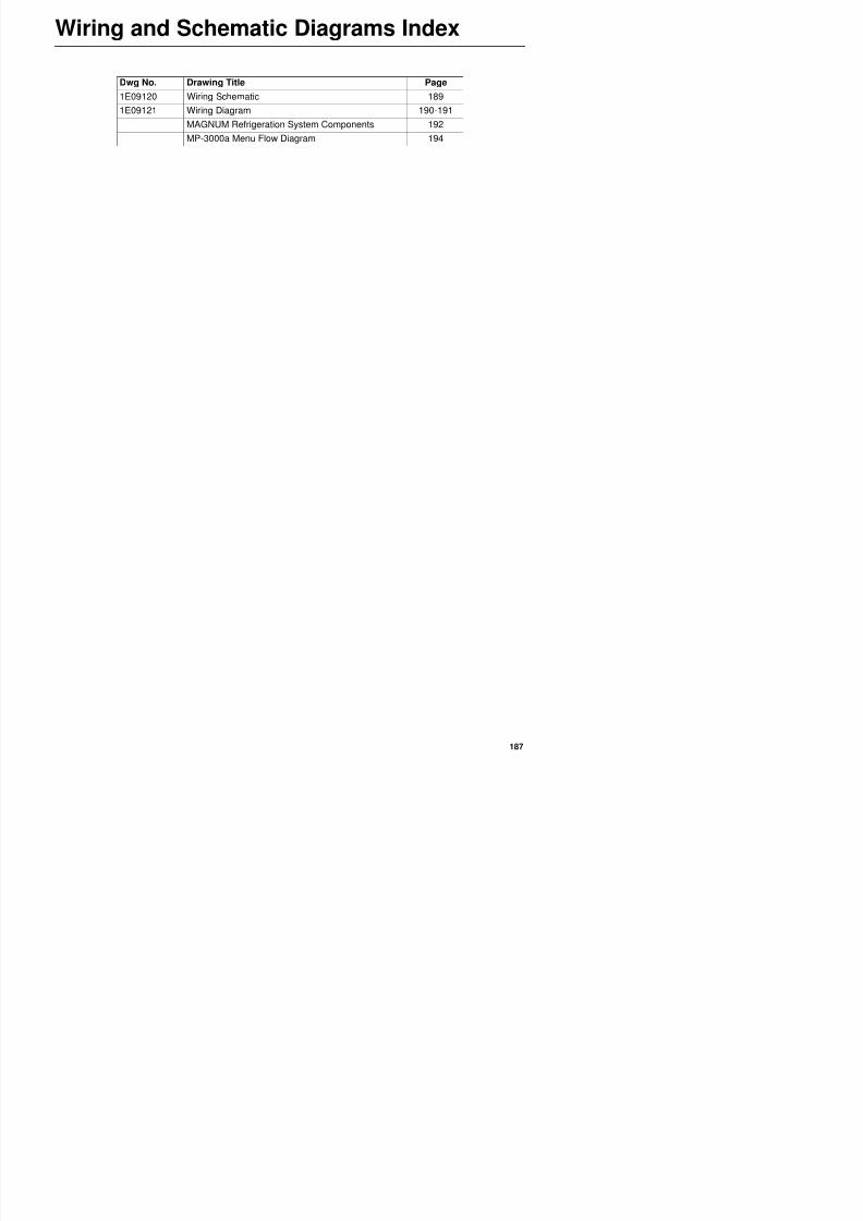
8/12/2019 Termo_King_Magnum_manual.pdf
http://slidepdf.com/reader/full/termokingmagnummanualpdf 187/194
Wiring and Schematic Diagrams Index

8/12/2019 Termo_King_Magnum_manual.pdf
http://slidepdf.com/reader/full/termokingmagnummanualpdf 188/194
Wiring Schematic
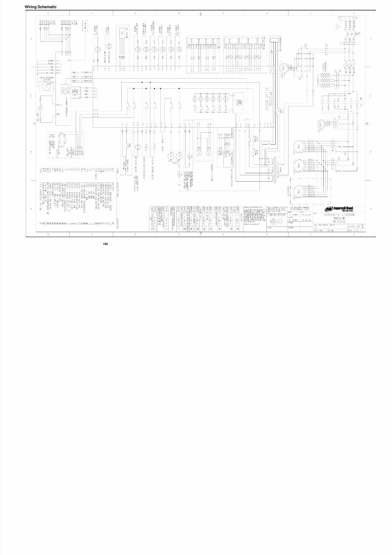
8/12/2019 Termo_King_Magnum_manual.pdf
http://slidepdf.com/reader/full/termokingmagnummanualpdf 189/194
189
Wiring Diagram–Page 1 of 2
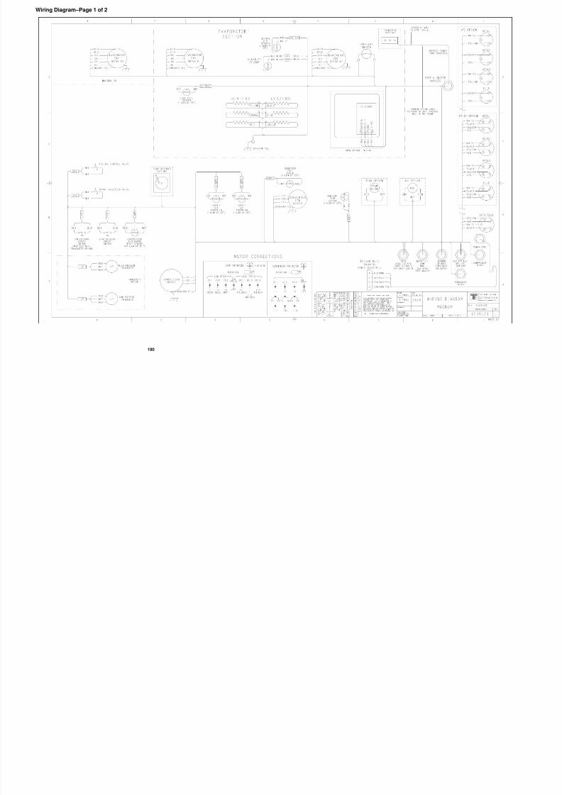
8/12/2019 Termo_King_Magnum_manual.pdf
http://slidepdf.com/reader/full/termokingmagnummanualpdf 190/194
190
Wiring Diagram–Page 2 of 2
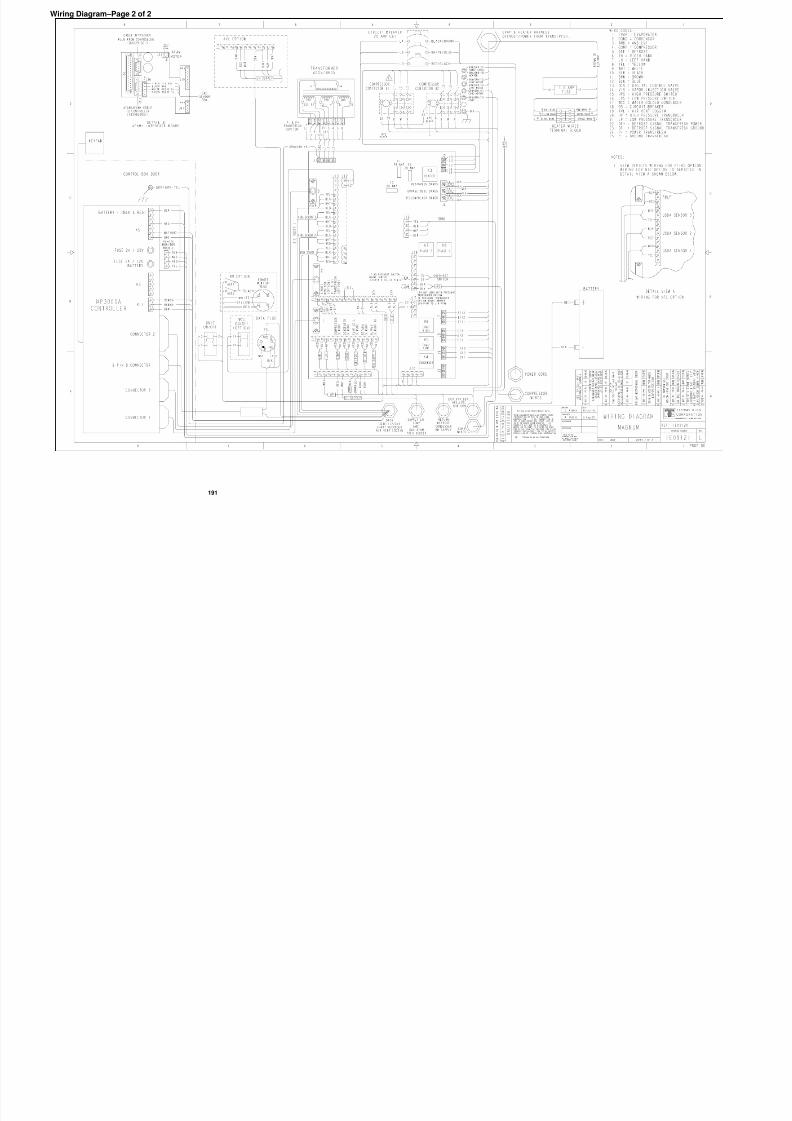
8/12/2019 Termo_King_Magnum_manual.pdf
http://slidepdf.com/reader/full/termokingmagnummanualpdf 191/194
191
CSR 40 Refrigeration System Components
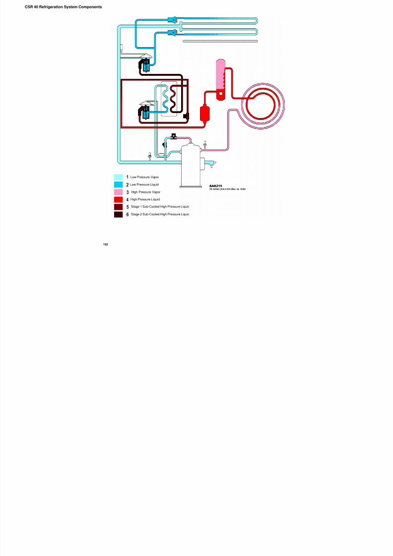
8/12/2019 Termo_King_Magnum_manual.pdf
http://slidepdf.com/reader/full/termokingmagnummanualpdf 192/194
192
High Pressure Vapor
High Pressure Liquid
Low Pressure Liquid
Stage 1 Sub-Cooled High Pressure Liquid
Stage 2 Sub-Cooled High Pressure Liquid
Low Pressure Vapor
TK 52234 (2/3)-4-CH (Rev. 0), 10/03
MAGNUM Components
1. Scroll Compressor
2. Discharge Service Valve
3. High Pressure Switch4. Condenser Coil
5. Receiver Tank
6. Pressure Relief
7. Sight Glass
8. Drier / Oil Filter
9. Economizer Heat Exchanger
10. Vapor Injection Valve
11. Economizer TXV
12. Evaporator TXV
13. Evaporator Coil
14. Heater
15 Low Pressure Switch
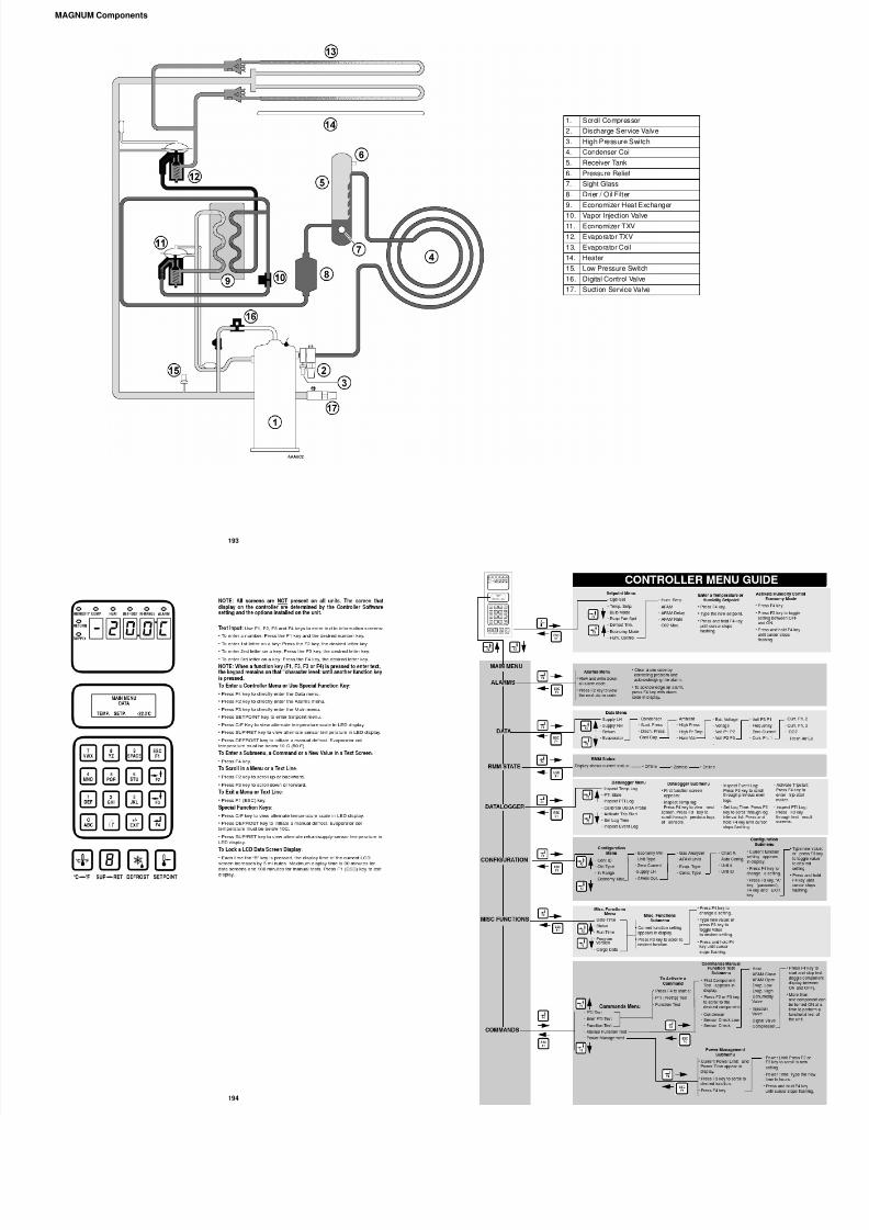
8/12/2019 Termo_King_Magnum_manual.pdf
http://slidepdf.com/reader/full/termokingmagnummanualpdf 193/194
193
15. Low Pressure Switch
16. Digital Control Valve
17. Suction Service Valve

8/12/2019 Termo_King_Magnum_manual.pdf
http://slidepdf.com/reader/full/termokingmagnummanualpdf 194/194


