Embed Size (px)
Citation preview

Term 3
Topic 3
Unit 1:
Mechanical systems
& control(machines, levers & their
functions)

MACHINES ARE ABLE TO:
-Increase amount of force to
move a bigger load
-This machine = FORCE MULTIPLIER
-Increase distance that object
moves
-This machine = DISTANCE MULTIPLIER

FORMULA FOR AMOUNT OF WORK DONE:
Work = Force x distance
W = F x d
J = N x m
Amount of work done (W) = measured in Joules (J)
Force (F) measured in Newtons (N)
Distance (d) measured in metres (m)

EXAMPLE:
-Wheelbarrow is pushed 50 m
-Using a force of 20 N
-How much work has been done?
Let’s see who can find this answer first!!! =D

EXAMPLE ANSWER:
Wheelbarrow is pushed 50 m = distance (d) in m
Using a force of 20 N = force (F) in N
How much work has been done? = Work (W) in J
Therefore
W = F x d
W = 20 N x 50 m
W = 100 Nm or 100 J

CLASS ACTIVITY:
-Car is moved 85 m
-Using a force of 120 N
-How much work has been done?
Let’s see who can find this answer first!!! =D

CLASS ACTIVITY:
1.What is the formula used for WORK DONE?
2.How much work did Jo do to push his toy car 6.4m with a force of 15N?
3.If Jo needed 45J to push his car 8m, then how much force did he need?
4.If Jo used 56N of force & 62J of work, then how far did he push his toycar?

MECHANISMS:
-DEFINITION:
-Different parts working together to perform a specific task
-They are the parts that make work easier
-Convert INPUT force to an OUTPUT force

A JACK used on a CAR:
-Turn the screw of jack = INPUT force
-Jack raised higher = PROCESS
-Car lifted up = OUTPUT force
-Is the jack a force multiplier
or a distance multiplier???
= FORCE MULTIPLIER (makes it easier to lift car)


MECHANICAL SYSTEM:
-DEFINITION:
-When a machine uses a mechanical appliance (like the screw of the jack) to provide force for movement
-OTHER MACHINES THAT USE OTHER SYSTEMS:
-Electrical systems (work with electricity)
-Hydraulic systems (work with liquid under pressure)
-Pneumatic systems (work with air under pressure)

CLASS ACTIVITY
Label the following as either:
Hydraulic
Or
Pneumatic
Or
Electrical
A
B
C
D
E
F

LEVERS:
-DEFINITION:
-Bar free to turn about a fixed point or pivoting point (FULCRUM)
-Are simple machines
-3 classes:
-A) first class levers
-B) second class levers
-C) third class levers
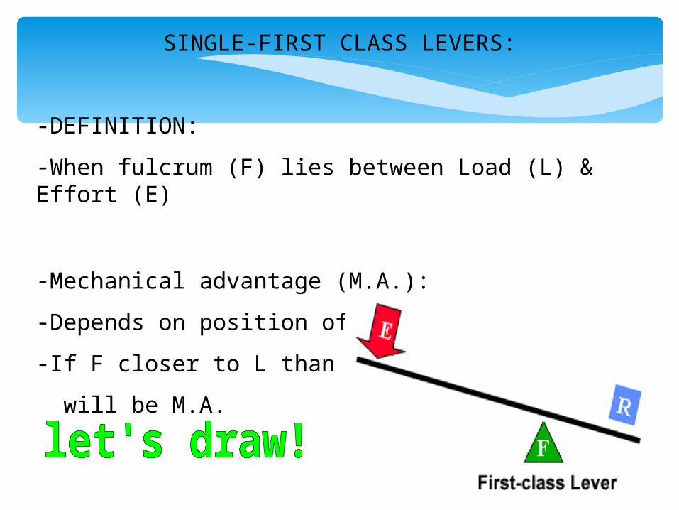
SINGLE-FIRST CLASS LEVERS:
-DEFINITION:
-When fulcrum (F) lies between Load (L) & Effort (E)
-Mechanical advantage (M.A.):
-Depends on position of fulcrum
-If F closer to L than E, then
will be M.A.
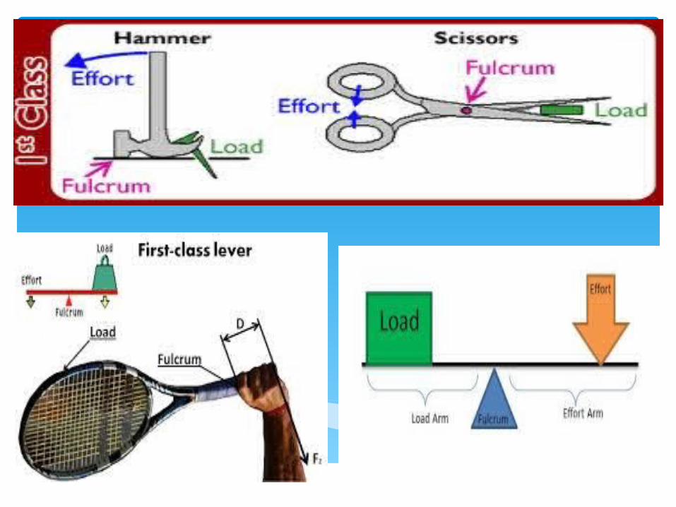

LINKED FIRST-CLASS LEVERS:
-DEFINITION:
-Some cases 2 levers linked together
at fulcrum e.g. pair of scissors
-Normal paper scissors blades equal in length to handle = NO M.A
-Pruning scissors long handle & short, strong blades = M.A. greater than 1
-Express as MA > 1
-i.e. less force to get work done

SINGLE-SECOND CLASS LEVERS:
-DEFINITION:
-When Load (L) is between Fulcrum (F) & Effort (E)
-Always gives some kind of
M.A.

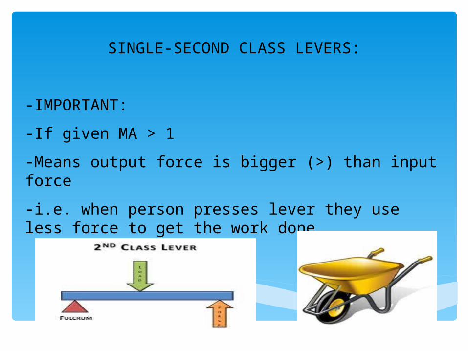
SINGLE-SECOND CLASS LEVERS:
-IMPORTANT:
-If given MA > 1
-Means output force is bigger (>) than input force
-i.e. when person presses lever they use less force to get the work done

LINKED SINGLE-SECOND CLASS LEVERS:
-DEFINITION:
-Formed when 2nd class levers joined at fulcrum
-E.g. office punch
-Gives M.A. > 1 (what does this mean?)
-Why???
-F fixed at a point where operator needs less Effort to perform the task

SINGLE-THIRD CLASS LEVERS:
-DEFINITION:
-Effort (E) is between Fulcrum (F) & Load (L)
-Never gives Mechanical Advantage (M.A. < 1)
-i.e. requires more effort than Weight of Load
-E.g.’s:
-Fishing rod
-Light duty stapler
-Pair of tweezers

SINGLE-THIRD CLASS LEVERS:
-IMPORTANT:
-Often small movement at 1 end will produce a larger movement at the other end
-E.g. fishing rod

LINKED THIRD-CLASS LEVERS:
-DEFINITION:
-Formed when 3rd class levers joined at fulcrum
-E.g. office stapler
-M.A. < 1
-Why???
-Effort too close to
fulcrum to give a
greater M.A.

CLASS ACTIVITY:
Identify the 3 different classes of levers
(Let’s do this together) – first draw the 3 lever classes
A B C

GEAR SYSTEMS
-FORCE DEFINITION:
-Make things move
-TORQUE DEFINITION:
-Force applied that causes an object to rotate around an axis
-COUNTER ROTATION:
-2 wheels rotating in opposition directions
-i.e. a gear consist of 2 such wheels
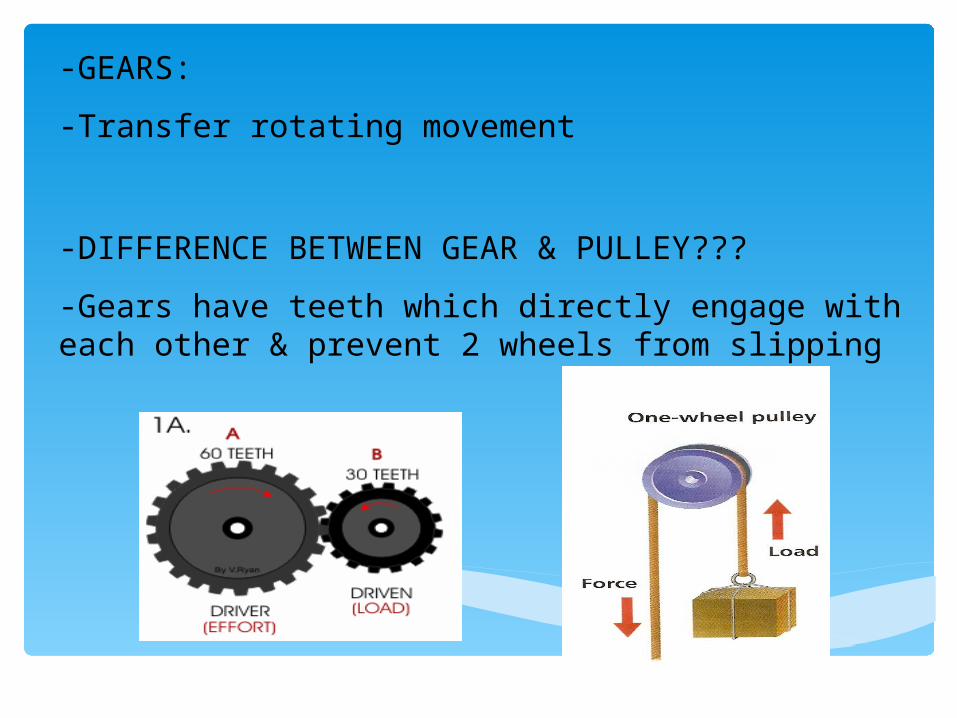
-GEARS:
-Transfer rotating movement
-DIFFERENCE BETWEEN GEAR & PULLEY???
-Gears have teeth which directly engage with each other & prevent 2 wheels from slipping
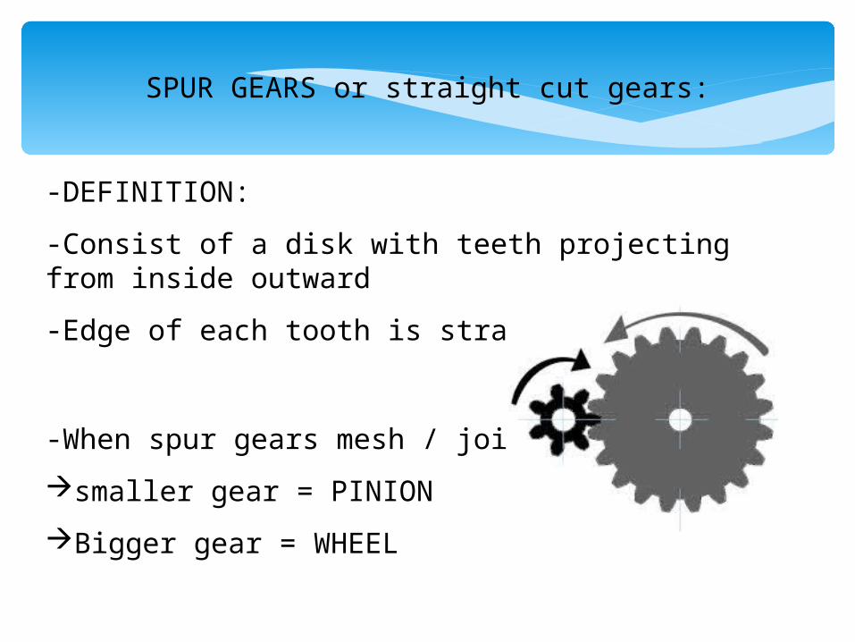
SPUR GEARS or straight cut gears:
-DEFINITION:
-Consist of a disk with teeth projecting from inside outward
-Edge of each tooth is straight
-When spur gears mesh / join
smaller gear = PINION
Bigger gear = WHEEL

SPUR GEARS or straight cut gears:
-1 gear turned by motor = DRIVER gear
-Driver gear meshes with other gear
-Second gear = DRIVEN gear
-Often spur gears are unequal sizes
-This means different numbers of teeth for each
-M.A. now produced

SPUR GEARS or straight cut gears:
-Smaller gear rotates faster vs bigger gear
-BUT
-Bigger gears TORQUE is greater (although turns slower)

HOW TO CALCULATE GEAR RATIO aka VELOCITY RATIO
•Gear ratio = number of teeth of the driven gear ----------------------------------------- number of teeth of the driven gear
•Velocity ratio is also used for gear ratio

CLASS ACTIVITY:
Lets work out the Velocity ratio of the spur gear below (let’s see who can do it first =D)
Don’t forget your ratio value & statement

BICYCLE (spur gear) EXAMPLE:
-Pedal gear = front gear DRIVER GEAR
-Differs in size to back gear DRIVEN GEAR
-Changing Velocity ratio forces cyclist to use more force on driver gear
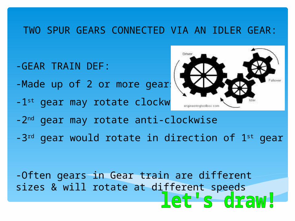
TWO SPUR GEARS CONNECTED VIA AN IDLER GEAR:
-GEAR TRAIN DEF:
-Made up of 2 or more gears
-1st gear may rotate clockwise
-2nd gear may rotate anti-clockwise
-3rd gear would rotate in direction of 1st gear
-Often gears in Gear train are different sizes & will rotate at different speeds

TWO SPUR GEARS CONNECTED VIA AN IDLER GEAR:
-IDLER GEAR:
-Forces 2 outer gears to turn in same direction
-Called SYNCHRONISATION
-NOTE:
-Could also make size of shape
the size to have them turn at
the same velocity

SUITABLE MATERIALS:
-IDLER GEAR FUNCTION:
-Influence rotation of 2 important gears
-Therefore Idler gear much smaller than other 2 gears & found between driven & driver gear
-Bears all force & wear of other 2 gears
-MUST BE: strong, hard material that wont break / affect speed & functioning of the other 2 gears
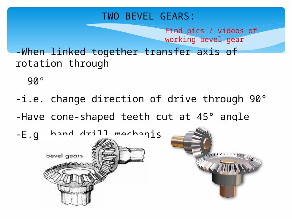
TWO BEVEL GEARS:
-When linked together transfer axis of rotation through
90°
-i.e. change direction of drive through 90°
-Have cone-shaped teeth cut at 45° angle
-E.g. hand drill mechanism
Find pics / videos of working bevel gear

Term 3
Topic 3
Unit 2:
Mechanical advantage
calculations

RATIOS:
-DEFINITION:
-Describes a relationship between 2 things in numbers
-i.e. the relative sizes of 2 or more things
-What does the ratio of 4:3 mean??
-E.g. there could be 4 oranges for every 3 apples
-If there are now 8 oranges
-Then 4 oranges x 2 = 8 oranges
-So 3 apples x 2 = 6 apples
What we do on the 1 side we do on the other side
Find videos of ratios

LEVERS & MECHANICAL ADVANTAGE:
-Levers give us mechanical advantage
-This means:
-Levers help us lift heavy weights with little effort
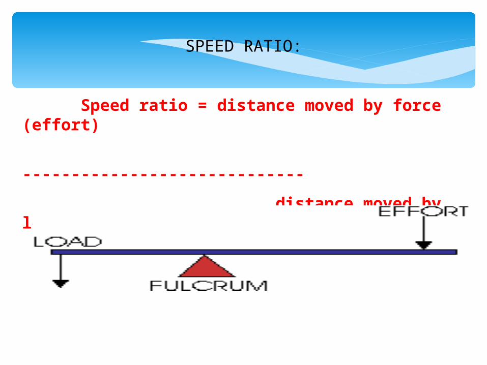
SPEED RATIO:
Speed ratio = distance moved by force (effort)
-----------------------------
distance moved by load

SPEED RATIO EXAMPLE:
Calculate the speed ratio of the mechanism if the distance moved by the force was 20 & the distance
moved by the load was 80
Let’s see who can do this first!! =D
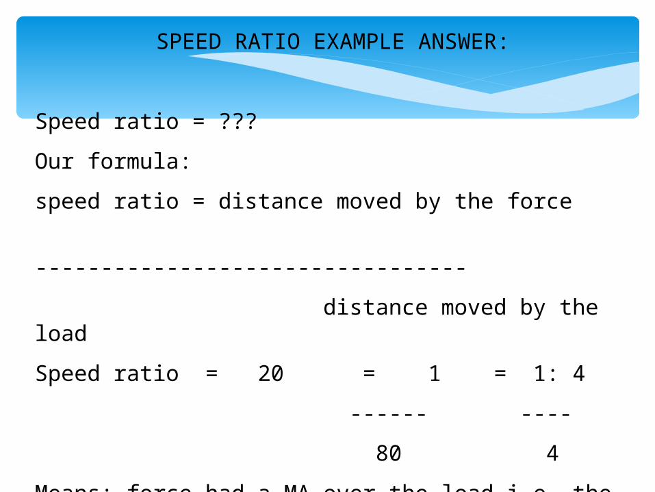
SPEED RATIO EXAMPLE ANSWER:
Speed ratio = ???
Our formula:
speed ratio = distance moved by the force
---------------------------------
distance moved by the load
Speed ratio = 20 = 1 = 1: 4
------ ----
80 4
Means: force had a MA over the load i.e. the force moved 1 x for every 4 x that the load moved

SPEED RATIO EXAMPLE:
What does this really mean???
Every 1 time the forefinger moved (i.e. its distance moved), the eraser moved 4 times
Therefore the lever is a DISTANCE MULTIPLIER!
Find pic of eraser on a lever system

MECHANICAL ADVANTAGE OF A MECHANISM:
MA = load
-----
force
Load & force are both measured in Newtons (N)
Newtons = unit of force Find videos of newtons

MECHANICAL ADVANTAGE OF A MECHANISM EXAMPLE:
Calculate the MA of a mechanism with a load of 40 and a force of 70.
Let’s see who can do this first!! =D
Find pics of load & effort

MECHANICAL ADVANTAGE OF A MECHANISM EXAMPLE ANSWER:
Calculate the MA of a mechanism with a load of 40 and a force of 70.
MA = ???
MA = Load = 40 = 1
------- ------ ------
Force 70 1.75
Find pic of thinking caps

1 NEWTON:
A force that is 1 N strong
= the weight of 100g mass
e.g. you experience 1 N of force when you hold a 100g slab of chocolate
So how many Newtons would you experience with a 650 g slab of chocolate???
= 6.5 N (i.e. 650g / 100 g = 6.5N)
Find pics of slab of chocolate
M.A. CALCULATIONS FOR GEARS USING RATIOS:
- When we mesh 2 gears together, they act similar to levers
- Each end of a gear’s tooth = similar to the end of a lever with a fulcrum at the gear’s centre
- Longer lever A is greater the force applied to the shaft of the driven gear
Find pics & video of MA for gears using ratios

- SHAFT DEFINITION:
-Drive shaft that transfers torgue (i.e. turning motion of a gear around a fixed point)
-Gears DO NOT ONLY increase speed & change direction
-BUT they also MULTIPLY TURNING FORCES

M.A. CALCULATIONS USING TOOTH RATIOS FOR GEARS:
Gear ratio (velocity ratio) = number of teeth of driven
------------------------------
number of teeth of driver
Calculate the gear ratio if the driven gear has 60 teeth & the driver gear has 15 teeth
Let’s see who can do this first!! =D

M.A. CALCULATIONS USING TOOTH RATIOS FOR GEARS ANSWER:
Gear ratio (velocity ratio) = number of teeth of driven
------------------------------
number of teeth of driver
Gear ratio = 60 = 4 = 4 : 1
------ ----
15 1
This means that the MA ratio is 4:1
So the driven gear turns 4 x more than the driver gear
CALCULATING GEAR WHEEL DIAMETER FOR GEARS:
A gear’s most NB feature is that gears of unequal sizes (diameters) can be combined to produce a MA
-A different arrangement of different gear sizes = a ‘gear ratio’
-& the number of teeth / gear diameter is used as the units
-Let’s determine the MA of a particular gear combination
Find pics & video of gear trains & MA for gear combinations

CALCULATING GEAR WHEEL DIAMETER FOR GEARS:
MA = output force
------------
input force
Calculate the MA if the output force is 60 N & the input force was 40 N
Answer: MA = 60 N = 1 = 1 N : 1.5 N
------- -------
40 N 1.5 N

CALCULATION USING VELOCITY RATIOS (i.e. gear ratios):
Velocity Ratio = Driver gear (the one connected to the
power)
-------------
Driven gear
We use the number of teeth of the gears to calculate VR (velocity ratio)

CALCULATION USING VELOCITY RATIOS (i.e. gear ratios):
Then:
We want to calculate the speed of the driven gear
So:
Our VR = 12 = 1 = 0.5
--- ---
24 2
If driven speed = 1 000 rpm
Then final speed = 1 000 rpm x VR (i.e. 0.5)
= 500 rpm

CALCULATION USING VELOCITY RATIOS EXTRA EXAMPLE:
Let’s see if you can do this one by yourself =D
The driver gear has 60 teeth
The driven gear has 30 teeth
What is the VR?
If the driven speed is 1 000 rpm?
What is the final speed of the driven gear?

CALCULATION USING VELOCITY RATIOS EXTRA EXAMPLE ANSWER:
VR = driver = 60 = 2 = 2 0r 2 , 0
------- ---- ---
driven 30 1
Driven speed = 1 000 rpm
So final driven speed = 1 000 rpm x VR
= 1 000 rpm x 2,0
= 2 000 rpm

Term 3
Topic 3
Unit 3:
COMMUNICATION
&
DESIGN SKILLS

REPRESENTING GEAR SYSTEMS GRAPHICALLY:
GRAPHICALLY DEFINITION:
Show a design through drawings, sketches, plans & diagrams
COUNTER ROTATING
Turning in opposite directions
How would we graphically represent this???

Find pics of gears graphically represented

REPRESENTING GEAR SYSTEMS GRAPHICALLY:
IDLER GEARS INBETWEEN SPUR GEARS
Let’s graphically represent this
Find pics of spur gear with idler gear graphically represented with rotation directions

REPRESENTING GEAR SYSTEMS GRAPHICALLY:
How would we represent the DRIVEN GEAR turning faster & turning slower????
Find pics of driven gear turning faster & slower graphically (look for driven gear being bigger & smaller than driver gear)

IMPORTANT TERMS:
OUTPUT VELOCITY DEFINITION:
The rate of speed of the output from an electronic device
FORCE MULTIPLIER DEFINITION:
Something that makes a given force more effective than that same force would be without it
Find pics output velocity & force multipliers