Embed Size (px)
Citation preview

OVERSEAS NETWORK
TERASAKI (EUROPE) LTD.80 Beardmore Way, Clydebank Industrial Estate, Clydebank, Glasgow G81 4HT SCOTLAND (UK)Telephone: 44-141 941-1940 / Fax: 44-141-952-9246 / E-mail: [email protected]
TERASAKI ITALIA s.r.l.Via Campania 4/6, 20090 Segrate, Milano, ITALYTelephone: 39-02-2137574 / Fax: 39-02-26922931 / E-mail: [email protected]
TERASAKI ESPAÑA, S.A.U.Roma, s/n 08400 Granollers, Barcelona, SPAINTelephone: 34-93-879-60-50 / Fax: 34-93-870-39-05 / E-mail: [email protected]
TERASAKI SKANDINAVISKA ABFrasarvagan 32, 142 50 Skogas, SWEDENTelephone: 468-556-28230 / Fax: 468-556-28239 / E-mail: [email protected]
TERASAKI CIRCUIT BREAKERS (S) PTE. LTD.9 Toh Guan Road East // 03-01 Alliance Building, SINGAPORE 608604 Telephone: 65-6744-9752 / Fax: 65-6748-7592 / E-mail: [email protected]
TERASAKI ELECTRIC (M) SDN. BHD.Lot 3, Jalan 16/13D, 40000 Shah Alam, Selangor Darul Ehsan, MALAYSIATelephone: 60-3-5549-3820/ Fax: 60-3-5549-3960 / E-mail: [email protected]
TERASAKI DO BRASIL LTDARua Cordovil, 259-Parada De Lucas, 21250-450 Rio De Janeiro-R.J., BRAZILTelephone: 55-21-3301-9898 / Fax: 55-21-3301-9861 / E-mail: [email protected]
TERASAKI ELECTRIC (CHINA) LIMITED72 Pacific Industrial Park, Xingtang Zengcheng, Guangzhou 511340, CHINATelephone: 86-20-8270-8556 / Fax: 86-20-8270-8586 / E-mail: [email protected]
ELECTRIC CO., LTD.Head Office: 7-2-10 Hannancho, Abenoku, Osaka, JAPANCircuit Breaker Division: 7-2-10 Kamihigashi, Hiranoku, Osaka, JAPANTelephone: 81-6-6791-9323 / Fax: 81-6-6791-9274 / E-mail: [email protected]
July 2004 Ref No. 04-M55EA
Ratings and specifications in this manual may be subject to change without notice.
Air Circuit BreakerInstruction Manual
Non-Automatic and AGR-11 protection relay models
Innovators in Protection Technology
04-M55EA
=
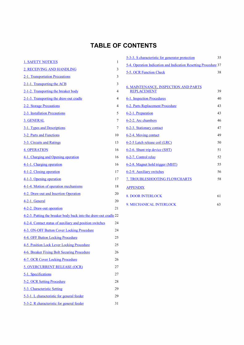
1. SAFETY NOTICES 1
2. RECEIVING AND HANDLING 3
2-1. Transportation Precautions 3
2-1-1. Transporting the ACB 3
2-1-2. Transporting the breaker body 4
2-1-3. Transporting the draw-out cradle 4
2-2. Storage Precautions 4
2-3. Installation Precautions 5
3. GENERAL 7
3-1. Types and Descriptions 7
3-2. Parts and Functions 10
3-3. Circuits and Ratings 13
4. OPERATION 16
4-1. Charging and Opening operation 16
4-1-1. Charging operation 16
4-1-2. Closing operation 17
4-1-3. Opening operation 17
4-1-4. Motion of operation mechanisms 18
4-2. Draw-out and Insertion Operation 20
4-2-1. General 20
4-2-2. Draw-out operation 21
4-2-3. Putting the breaker body back into the draw-out cradle 22
4-2-4. Contact status of auxiliary and position switches 24
4-3. ON-OFF Button Cover Locking Procedure 24
4-4. OFF Button Locking Procedure 25
4-5. Position Lock Lever Locking Procedure 25
4-6. Breaker Fixing Bolt Securing Procedure 26
4-7. OCR Cover Locking Procedure 26
5. OVERCURRENT RELEASE (OCR) 27
5-1. Specifications 27
5-2. OCR Setting Procedure 28
5-3. Characteristic Setting 29
5-3-1. L characteristic for general feeder 29
5-3-2. R characteristic for general feeder 31
5-3-3. S characteristic for generator protection 35
5-4. Operation Indication and Indication Resetting Procedure 37
5-5. OCR Function Check 38
6. MAINTENANCE, INSPECTION AND PARTSREPLACEMENT 39
6-1. Inspection Procedures 40
6-2. Parts Replacement Procedure 43
6-2-1. Preparation 43
6-2-2. Arc chambers 46
6-2-3. Stationary contact 47
6-2-4. Moving contact 49
6-2-5 Latch release coil (LRC) 50
6-2-6. Shunt trip device (SHT) 51
6-2-7. Control relay 52
6-2-8. Magnet hold trigger (MHT) 55
6-2-9. Auxiliary switches 56
7. TROUBLESHOOTING FLOWCHARTS 58
APPENDIX
8. DOOR INTERLOCK 61
9. MECHANICAL INTERLOCK 63
TABLE OF CONTENTS
KRB-5237d1
1. SAFETY NOTICESThank you for purchasing the TERASAKI AR-series Air Circuit Breaker (TemPower2).
This chapter contains important safety information.
Be sure to carefully read these safety notices, instruction in this manual, and other documents accompanying the Air Circuit
Breaker (hereinafter referred to as the ACB) to familiarize yourself with safe and correct procedures or practices before
installing, operating, or servicing the ACB.
In this manual, safety notices are divided into “DANGER” and “CAUTION” according to the hazard level:
DANGER : A danger notice with this symbol indicates a potentially hazardous situation which, if not avoided, could
result in death or serious injury.
CAUTION : A caution notice with this symbol indicates a potentially hazardous situation which, if not avoided, may result
in minor or moderate injury and/or property damage.
Note that failure to observe a caution notice could result in serious injury/damage in some situations. Because safety notices
contain important information, be sure to read and observe them.
Transportation Precaution DANGER
Never stand under the ACB that has been lifted or suspended by a lifter or lifting attachments. The weight of the ACB maycause serious injury.
Installation Precautions CAUTION
Electrical work must be done by competent persons. Do not place the ACB in such an area that is subject to high temperatures, high humidity, dusty air, corrosive gases, strongvibration and shock, or other unusual conditions. Mounting the ACB in such an area could cause a fire or malfunction.
Be careful to prevent foreign objects (such as debris, concrete powder, dust, chippings, and iron powder) and oil orrainwater from entering the ACB. These materials inside the ACB could cause a fire or malfunction.
Prior to commencing any work on the ACB, open an upstream circuit breaker or the like to isolate all sources ofpower/voltage. Otherwise, electric shock may result.
Fix the draw-out cradle of the ACB firmly on a flat, level surface using mounting screws. Otherwise, the draw-outoperation may cause the breaker body or the draw-out cradle to fall, resulting in damage to the ACB or personal injury.
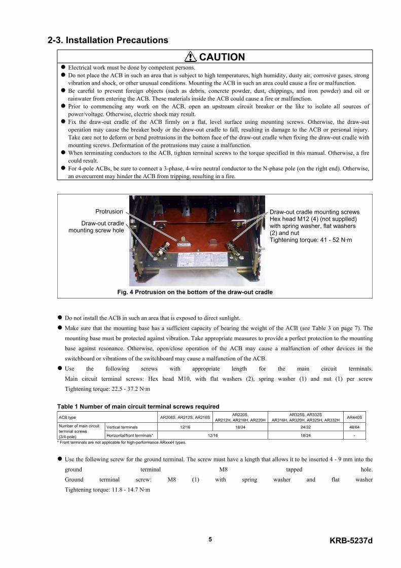
Take care not to deform or bend protrusions in the bottom face of the draw-out cradle when fixing the draw-out cradle withmounting screws. Deformation of the protrusions may cause a malfunction.
When terminating conductors to the ACB, tighten terminal screws to the torque specified in this manual. Otherwise, a firecould result.
For 4-pole ACBs, be sure to connect a 3-phase, 4-wire neutral conductor to the N-phase pole (on the right end). Otherwise,an overcurrent may hinder the ACB from tripping, resulting in a fire.
Operation Precautions DANGER
Never touch live terminal parts. Doing so will result in electric shock. Do not leave the ACB body in the draw-out position. If the ACB body is accidentally dropped, its weight may causeserious injury.
CAUTION Do not force down the charging handle after completion of manual charging operation. Doing so may cause a malfunction. The permissible operating voltage of the spring charging motor is 85 to 110% of the rated ac voltage or 75 to 110% of therated dc voltage. Be sure to supply a voltage within the above ranges to the motor. Otherwise, a malfunction, burnout, or firemay result.
Operation Precautions (continued) CAUTION
Repeated open/close operation by the motor charging mechanism without pause should not exceed 15 times. If repeatedcontinuous open/close operation is inevitable, a pause of at least 20 minutes should be provided after the repetitions of 15times. Otherwise, a spring charging motor may be burnt out.
Do not bring your hand or face close to arc gas vent of the arc chamber while the ACB is closed. Otherwise, a burn mayresult from high-temperature arc gas blowing out of the arc gas vent when the ACB trips open.
If the ACB trips open automatically, remove the cause of tripping operation before re-closing the ACB. Otherwise, a firecould result.
If the ACB has the breaker fixing bolts, be sure to loose the fixing bolts before draw-out operation. Otherwise, damage tothe ACB may result.
Make sure the draw-out cradle is secured with mounting screws before inserting or drawing out the breaker body.Otherwise, the insertion or draw-out operation may cause the breaker body or the draw-out cradle to fall, resulting indamage to the ACB or personal injury.
When retracting the draw-out rail into the draw-out cradle, be sure to push the rail end. Do not hold the hook pin, bodystopper, or body stopper shaft. Doing so may cause your fingers to be pinched, resulting in injury.
Do not forcedly turn the draw-out handle clockwise when the breaker body is in the “CONN.” position. Doing so maycause a malfunction.
If the ACB has the breaker fixing bolts, make sure the bolts on both sides are securely tightened before using the ACB.Loosened fixing bolts may cause a malfunction of the ACB, in particular when it is installed in such an area that is subjectto strong vibrations.
OCR (Overcurrent Release) Handling Precautions CAUTION
OCR field tests and setting changes must be performed by competent persons. Use a small flatblade screwdriver with a torque of not more than 0.1 N·m or a force of not more than 0.1 N when adjustingthe setting switches (rotary step switches or slide switches). An excessive torque or force may cause a malfunction.
After completion of OCR tests, be sure to return the setting switches to the original positions. Failure to do so may cause afire or burnout.
Maintenance and Inspection Precautions CAUTION
ACB maintenance, inspection and parts replacement must be performed by competent persons. Do not touch ACB current carrying parts and ACB structural parts close to a current carrying part immediately after theACB trips open. Remaining heat may cause a burn.
Prior to commencing any work on the ACB, open an upstream circuit breaker or the like to isolate all sources ofpower/voltage from the main and control circuits. Otherwise, electric shock may result.
Take care to avoid adhesion of dust to main and control circuit contacts. Dust on the contacts may result in a fire. Prior to commencing maintenance, inspection, or parts replacement, make sure that the closing springs are released and theACB is open. Otherwise, unintentional open/close operation may lead to fingers or tools to be pinched by the open/closemechanism, resulting in injury.
Retighten the terminal screws periodically to the specified torque. Otherwise, a fire could result. When grinding a contact tip, be careful to prevent grinding dust from entering the breaker operating mechanism. Wipe thetip clean after grinding. Otherwise, a malfunction or fire could result.
Do not perform dielectric withstand tests under other conditions than specified. Doing so may cause a malfunction. Be sure to reinstall the arc chamber if removed. Failure to do so or incorrect installation of the arc chamber may result in afire or burn.
When charging the closing springs or performing open/close operation of the ACB with the arc chamber, front cover and/orside covers removed during maintenance or inspection work, do not touch parts other than those required for the aboveoperation (charging handle, ON/OFF buttons, moving core and the like). Doing so may cause fingers or tools to be pinched,resulting in injury.
When replacing an auxiliary, do not damage the control wire for the auxiliary or pinch the wire between the auxiliary andthe breaker body. Doing so may cause a malfunction.
KRB-5237d3
2. RECEIVING AND HANDLINGUpon receipt of your ACB, check the following. If you have any question or problem, contact us at the indicated on the back
cover of this manual.
Check that the ACB received is as ordered and that the accessories are as specified.
Check that the ACB is not damaged during shipment.
2-1. Transportation Precautions
DANGER Never stand under the ACB that has been lifted or suspended by a lifter or lifting attachments. If the ACB body isaccidentally dropped, its weight may cause serious injury.
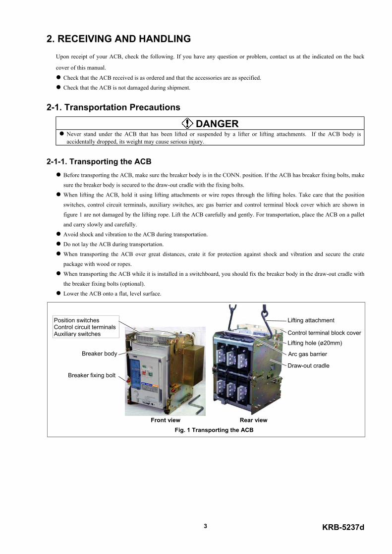
2-1-1. Transporting the ACB Before transporting the ACB, make sure the breaker body is in the CONN. position. If the ACB has breaker fixing bolts, make
sure the breaker body is secured to the draw-out cradle with the fixing bolts.
When lifting the ACB, hold it using lifting attachments or wire ropes through the lifting holes. Take care that the position
switches, control circuit terminals, auxiliary switches, arc gas barrier and control terminal block cover which are shown in
figure 1 are not damaged by the lifting rope. Lift the ACB carefully and gently. For transportation, place the ACB on a pallet
and carry slowly and carefully.
Avoid shock and vibration to the ACB during transportation.
Do not lay the ACB during transportation.
When transporting the ACB over great distances, crate it for protection against shock and vibration and secure the crate
package with wood or ropes.
When transporting the ACB while it is installed in a switchboard, you should fix the breaker body in the draw-out cradle with
the breaker fixing bolts (optional).
Lower the ACB onto a flat, level surface.
Breaker fixing bolt
Breaker body
Draw-out cradle
Lifting hole (ø20mm)
Lifting attachmentPosition switchesControl circuit terminalsAuxiliary switches
Arc gas barrier
Control terminal block cover
Front view Rear viewFig. 1 Transporting the ACB

2-1-2. Transporting the breaker body Use an optional lifter or lifting plate to transfer the breaker body.
When transporting the breaker body on a lifter, move the lifter with the lifter fork held at the lowest possible position.
Take care not to exert forces on the front cover and the control circuit contacts shown in Fig. 2 . Otherwise, a deformation or damage may
result.
2-1-3. Transporting the draw-out cradle When transporting the draw-out cradle, hold it using lifting attachments or wire ropes through the lifting holes or carry it by the portions
(4 points) marked with the arrows shown in Fig 3. When carrying the draw-out cradle, take care not to exert forces on the arc gas barrier,
the draw-out arm, the position switches, the auxiliary switches, the control circuit terminals, the control terminal block cover, and the
control circuit contacts.
2-2. Storage PrecautionsIt is recommended that the ACB be used as soon as you have received it. If it is necessary to store the ACB, note the following:
Store the ACB in a dry indoor location to prevent condensation due to sudden changes in ambient temperature. Condensation has a
harmful effect on the ACB insulation.
Store the ACB in a clean place free of corrosive gases and dust. In particular, exposure to a mixture of moisture and cement dust may
cause corrosion damage to metal parts of the ACB.
Place the ACB on a flat, level surface in its normal position (Do not lay the ACB).
Do not place the ACB directly on the floor. Do not stack the ACBs during storage.
Front cover
Control circuitcontact
Lifting plate
Front view Rear view
Fig. 2 Transporting the breaker body
Lifting hole (ø20mm)
Lifting attachmentPosition switchesControl circuit terminalsAuxiliary switches
Arc gas barrier
Control terminal block cover
Draw-out armControl circuit contacts
Front view Rear view
Fig. 3 Transporting the draw-out cradle
KRB-5237d5
2-3. Installation Precautions
CAUTION Electrical work must be done by competent persons. Do not place the ACB in such an area that is subject to high temperatures, high humidity, dusty air, corrosive gases, strongvibration and shock, or other unusual conditions. Mounting the ACB in such an area could cause a fire or malfunction.
Be careful to prevent foreign objects (such as debris, concrete powder, dust, chippings, and iron powder) and oil orrainwater from entering the ACB. These materials inside the ACB could cause a fire or malfunction.
Prior to commencing any work on the ACB, open an upstream circuit breaker or the like to isolate all sources ofpower/voltage. Otherwise, electric shock may result.
Fix the draw-out cradle of the ACB firmly on a flat, level surface using mounting screws. Otherwise, the draw-outoperation may cause the breaker body or the draw-out cradle to fall, resulting in damage to the ACB or personal injury.Take care not to deform or bend protrusions in the bottom face of the draw-out cradle when fixing the draw-out cradle withmounting screws. Deformation of the protrusions may cause a malfunction.
When terminating conductors to the ACB, tighten terminal screws to the torque specified in this manual. Otherwise, a firecould result.
For 4-pole ACBs, be sure to connect a 3-phase, 4-wire neutral conductor to the N-phase pole (on the right end). Otherwise,an overcurrent may hinder the ACB from tripping, resulting in a fire.
Do not install the ACB in such an area that is exposed to direct sunlight.
Make sure that the mounting base has a sufficient capacity of bearing the weight of the ACB (see Table 3 on page 7). The
mounting base must be protected against vibration. Take appropriate measures to provide a perfect protection to the mounting
base against resonance. Otherwise, open/close operation of the ACB may cause a malfunction of other devices in the
switchboard or vibrations of the switchboard may cause a malfunction of the ACB.
Use the following screws with appropriate length for the main circuit terminals.
Main circuit terminal screws: Hex head M10, with flat washers (2), spring washer (1) and nut (1) per screw
Tightening torque: 22.5 - 37.2 N·m
Table 1 Number of main circuit terminal screws requiredACB type AR208S, AR212S, AR216S AR220S,
AR212H, AR216H, AR220HAR325S, AR332S
AR316H, AR320H, AR325H, AR332H AR440S
Vertical terminals 12/16 18/24 24/32 48/64Number of main circuitterminal screws(3/4-pole) Horizontal/front terminals* 12/16 18/24 -
* Front terminals are not applicable for high-performance ARxxxH types.
Use the following screw for the ground terminal. The screw must have a length that allows it to be inserted 4 - 9 mm into the
ground terminal M8 tapped hole.
Ground terminal screw: M8 (1) with spring washer and flat washer
Tightening torque: 11.8 - 14.7 N·m
Draw-out cradle mounting screwsHex head M12 (4) (not supplied)with spring washer, flat washers(2) and nutTightening torque: 41 - 52 N·m
Draw-out cradlemounting screw hole
Protrusion
Fig. 4 Protrusion on the bottom of the draw-out cradle

Use the receptacles shown in Table 2 to make connections with plug-in tab terminals (#187) of position switches, control
circuit terminals, and auxiliary switches.
Table 2 Receptacles for #187 tab terminalsWire thickness (mm2) AWG Recommended terminals Applicable crimp tool Manufacturer
0.75 - 1.25 18 - 16 TMEDN480509-FA2 14 TMEDN480520-FA
NH-32 NICHIFU
The following procedure makes it easy to make connections with plug-in tab terminals (#187) of position switches, control
circuit terminals, and auxiliary switches.
(1) Draw out the breaker body to the removed position, and remove it using an optional lifter or lifting plate. Refer to
sections 4-2-2 and 2-1-2.
(2) If the ACB is equipped with the control terminal block cover, loosen both the cover fixing screws and remove the cover.
(3) Remove the terminal block fixing screws shown in Fig. 5.
(4) Tilt the terminal block down as shown in Fig. 6. After connecting wires, tilt the terminal block up again and fix it with the
terminal block fixing screws.
If any work is done near the ACB that have been installed, protect the openings of the ACB with appropriate covers to prevent
spatters, metal chips, wire cuttings or other foreign objects from entering the ACB.
Terminal block fixing screwsHex head M6 x 10 (4) (red),with spring washer and flatwasherTightening torque: 4.7 - 5.9 N·m
Auxiliary switches
Cover fixing screw
Fig. 5 Terminal block fixing screws
Auxiliary switch terminal screw(Control terminal screw)(Position switch terminal screw)Pan head M4 x 8,with spring washer and terminalwasherTightening torque: 1.3 - 1.7 N·m
Fig. 6 Terminal block tilted down
KRB-5237d7
3. GENERAL3-1. Types and Descriptions
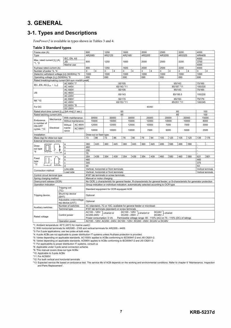
TemPower2 is available in types shown in Tables 3 and 4.
Table 3 Standard typesFrame size (A) 800 1250 1600 2000 2500 3200 4000Type AR208S AR212S AR216S AR220S AR325S AR332S AR440S
IEC, EN, AS 4000JIS 3700Max. rated current [In] (A)
*1, *2Marine use
800 1250 1600 2000 2500 32004000
N-phase rated current (A) 800 1250 1600 2000 2500 3200 4000Number of poles *3, *4 3 4 3 4 3 4 3 4 3 4 3 4 3 4Dielectric withstand voltage [Ui] (50/60Hz) *5 1000 1000 1000 1000 1000 1000 1000Operating voltage [Ue] (50/60Hz) *6 690 690 690 690 690 690 690Rated breaking/making current [kA sym rms/kA peak]
AC 690V *7 50/105 65/143 75/165IEC ,EN, AS [ICS = ICU] AC 440V 65/143 *11 85/187 *11 100/220AC 550V 50/105 65/143 75/165AC 460VJISAC 220V 65/143 85/195.5 100/230
AC 690V 50/115 65/153 75/179NK *10 AC 450V 65/153 *11 85/201 *11 100/245DC 600V *8For DC DC 250V 40/40
Rated short-time current [ICW] [kA rms] (1 sec.) 65 85 100Rated latching current (kA) 65 85 100
With maintenance 30000 30000 30000 25000 20000 20000 15000Mechanical Without maintenance 15000 15000 15000 12000 10000 10000 8000AC 460V 12000 12000 12000 10000 7000 7000 3000
Endurancein number ofON-OFFcycles *13 Electrical
Withoutmainte-nance
AC 690V 10000 10000 10000 7000 5000 5000 2500
Installation Draw-out or fixed typeMass (kg) for draw-out type 73 86 73 86 76 90 79 94 105 125 105 125 139 176External dimensions (mm)
a 360 445 360 445 360 445 360 445 466 586 466 586 - -b 460 -c 290 -
Draw-out type*9
d 75 -a 354 439 354 439 354 439 354 439 460 580 460 580 631 801b 460 460c 345 375
Fixedtype*12
d 40 53Line side Vertical, horizontal or front terminals Vertical terminalsConnection method Load side Vertical, horizontal or front terminals Vertical terminals
Control circuit terminal type #187 tab terminals or screw terminalsSpring charging method Manual or motor chargingOvercurrent release (OCR) No OCR, L-characteristic for general feeder, R-characteristic for general feeder, or S-characteristic for generator protectionOperation indication Group indication or individual indication; automatically selected according to OCR type
Tripping coil(TC) Standard equipment for OCR-equipped ACB
Shunt trip device(SHT) OptionalTripping device
Adjustable undervoltagetrip device (UVT) Optional
Number of switches 4C (standard), 7C or 10C; available for general feeder or microloadAuxiliary switches Terminal type #187 tab terminals (standard) or screw terminals
Control powerAC100 - 120V DC100 - 125V DC24VAC200-240V DC200 - 250V DC48VPower consumption: 5 VA Permissible voltage range: 85 - 110% (AC) or 75 - 110% (DC) of ratingsRated voltage
Operation power AC100 - 120V, AC200 - 240V, DC100 - 125V, DC200 - 250V, DC24V or DC48V
*1: Ambient temperature: 40°C (45°C for marine used))*2: With horizontal terminals for AR208S - 216S and vertical terminals for AR220S - 440S*3: For 2-pole applications, use two poles at both ends. *4: 4-pole ACBs are not applicable to power distribution IT systems unless N-phase protection is provided. *5: Varies depending on applicable standards. AC1000V applies to ACBs conforming to IEC60947-2 and JIS C8201-2. *6: Varies depending on applicable standards. AC690V applies to ACBs conforming to IEC60947-2 and JIS C8201-2. *7: For applicability to power distribution IT systems, consult us*8: Applicable under 3-pole serial connection scheme. *9: This manual covers draw-out type ACBs. *10: Applicable to 3-pole ACBs*11: For AC500V*12: For both vertical and horizontal terminals*13: Expected service life based on endurance test. The service life of ACB depends on the working and environmental conditions. Refer to chapter 6 “Maintenance, Inspection
and Parts Replacement”.
shared or shared or shared
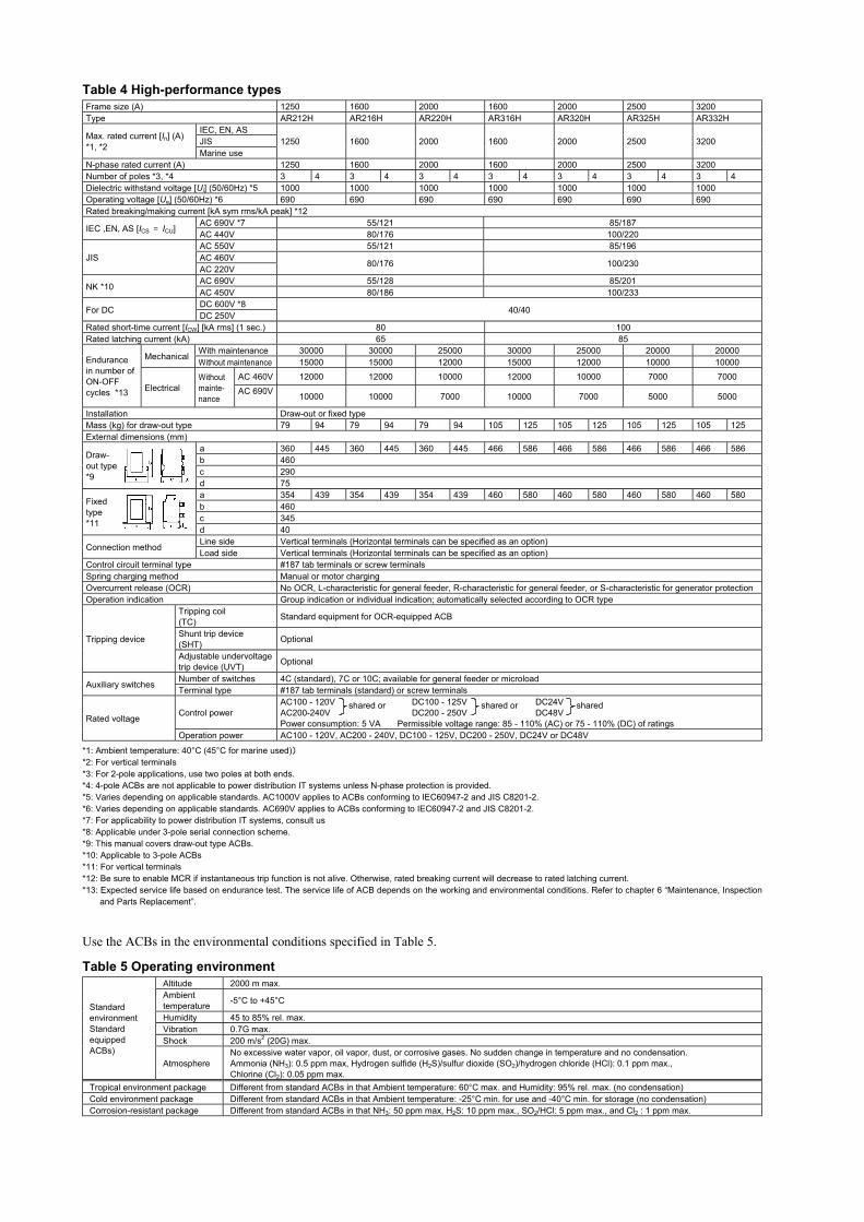
Table 4 High-performance typesFrame size (A) 1250 1600 2000 1600 2000 2500 3200Type AR212H AR216H AR220H AR316H AR320H AR325H AR332H
IEC, EN, ASJISMax. rated current [In] (A)
*1, *2Marine use
1250 1600 2000 1600 2000 2500 3200
N-phase rated current (A) 1250 1600 2000 1600 2000 2500 3200Number of poles *3, *4 3 4 3 4 3 4 3 4 3 4 3 4 3 4Dielectric withstand voltage [Ui] (50/60Hz) *5 1000 1000 1000 1000 1000 1000 1000Operating voltage [Ue] (50/60Hz) *6 690 690 690 690 690 690 690Rated breaking/making current [kA sym rms/kA peak] *12
AC 690V *7 55/121 85/187IEC ,EN, AS [ICS = ICU] AC 440V 80/176 100/220AC 550V 55/121 85/196AC 460VJISAC 220V 80/176 100/230
AC 690V 55/128 85/201NK *10 AC 450V 80/186 100/233DC 600V *8For DC DC 250V 40/40
Rated short-time current [ICW] [kA rms] (1 sec.) 80 100Rated latching current (kA) 65 85
With maintenance 30000 30000 25000 30000 25000 20000 20000Mechanical Without maintenance 15000 15000 12000 15000 12000 10000 10000AC 460V 12000 12000 10000 12000 10000 7000 7000
Endurancein number ofON-OFFcycles *13 Electrical
Withoutmainte-nance
AC 690V 10000 10000 7000 10000 7000 5000 5000
Installation Draw-out or fixed typeMass (kg) for draw-out type 79 94 79 94 79 94 105 125 105 125 105 125 105 125External dimensions (mm)
a 360 445 360 445 360 445 466 586 466 586 466 586 466 586b 460c 290
Draw-out type*9
d 75a 354 439 354 439 354 439 460 580 460 580 460 580 460 580b 460c 345
Fixedtype*11
d 40Line side Vertical terminals (Horizontal terminals can be specified as an option)Connection method Load side Vertical terminals (Horizontal terminals can be specified as an option)
Control circuit terminal type #187 tab terminals or screw terminalsSpring charging method Manual or motor chargingOvercurrent release (OCR) No OCR, L-characteristic for general feeder, R-characteristic for general feeder, or S-characteristic for generator protectionOperation indication Group indication or individual indication; automatically selected according to OCR type
Tripping coil(TC) Standard equipment for OCR-equipped ACB
Shunt trip device(SHT) OptionalTripping device
Adjustable undervoltagetrip device (UVT) Optional
Number of switches 4C (standard), 7C or 10C; available for general feeder or microloadAuxiliary switches Terminal type #187 tab terminals (standard) or screw terminals
Control powerAC100 - 120V DC100 - 125V DC24VAC200-240V DC200 - 250V DC48VPower consumption: 5 VA Permissible voltage range: 85 - 110% (AC) or 75 - 110% (DC) of ratingsRated voltage
Operation power AC100 - 120V, AC200 - 240V, DC100 - 125V, DC200 - 250V, DC24V or DC48V
*1: Ambient temperature: 40°C (45°C for marine used))*2: For vertical terminals*3: For 2-pole applications, use two poles at both ends. *4: 4-pole ACBs are not applicable to power distribution IT systems unless N-phase protection is provided. *5: Varies depending on applicable standards. AC1000V applies to ACBs conforming to IEC60947-2 and JIS C8201-2. *6: Varies depending on applicable standards. AC690V applies to ACBs conforming to IEC60947-2 and JIS C8201-2. *7: For applicability to power distribution IT systems, consult us*8: Applicable under 3-pole serial connection scheme. *9: This manual covers draw-out type ACBs. *10: Applicable to 3-pole ACBs*11: For vertical terminals*12: Be sure to enable MCR if instantaneous trip function is not alive. Otherwise, rated breaking current will decrease to rated latching current.*13: Expected service life based on endurance test. The service life of ACB depends on the working and environmental conditions. Refer to chapter 6 “Maintenance, Inspection
and Parts Replacement”.
Use the ACBs in the environmental conditions specified in Table 5.
Table 5 Operating environmentAltitude 2000 m max. Ambienttemperature -5°C to +45°C
Humidity 45 to 85% rel. max.Vibration 0.7G max. Shock 200 m/s2 (20G) max.
StandardenvironmentStandardequippedACBs)
AtmosphereNo excessive water vapor, oil vapor, dust, or corrosive gases. No sudden change in temperature and no condensation.Ammonia (NH3): 0.5 ppm max, Hydrogen sulfide (H2S)/sulfur dioxide (SO2)/hydrogen chloride (HCl): 0.1 ppm max.,Chlorine (Cl2): 0.05 ppm max.
Tropical environment package Different from standard ACBs in that Ambient temperature: 60°C max. and Humidity: 95% rel. max. (no condensation)Cold environment package Different from standard ACBs in that Ambient temperature: -25°C min. for use and -40°C min. for storage (no condensation)Corrosion-resistant package Different from standard ACBs in that NH3: 50 ppm max, H2S: 10 ppm max., SO2/HCl: 5 ppm max., and Cl2 : 1 ppm max.
shared or shared or shared
KRB-5237d9
Table 6 shows the dielectric withstand voltage and the insulation resistance of the ACBs.
CAUTION Do not perform dielectric withstand/insulation resistance tests under other conditions than specified. Doing so may cause amalfunction.
Table 6 Dielectric withstand voltage and insulation resistance
Circuit Dielectric withstand voltage (50/60Hz)Impulse
withstand voltageUimp
Insulationresistance
(DC500V Meggerused)
Main circuit Between poles, and terminal group and ground AC3500V 1 minute 12kV 300MΩFor general feeder Between terminal group and ground AC2500V 1 minute 6kV 100MΩAuxiliary
switches For microload Between terminal group and ground AC2000V 1 minute 4kV 100MΩPosition switches Between terminal group and ground AC2000V 1 minute 4kV 100MΩOvercurrent release Between terminal group and ground AC2000V 1 minute 4kV 100MΩ
Controlcircuit
Undervoltage trip device,Reverse power trip device Between terminal group and ground AC2500V 1 minute 6kV 100MΩ
Other accessories Between terminal group and ground AC2000V 1 minute 4kV 100MΩ
The above data applies to new ACBs. Device terminals within ACBs are not covered. Use a DC500V Megger to measure the insulation resistance.
Table 7 shows the internal resistance and power consumption of the ACBs.Table 7 Internal resistance and power consumption
Type AR208S AR212S AR216S AR220S AR325S AR332S AR440SFrame size (A) 800 1250 1600 2000 2500 3200 4000DC internal resistance (mΩ) (for 1-pole ACB) 0.030 0.030 0.028 0.024 0.014 0.014 0.014AC power consumption (W) (for 3-pole ACB) 170 310 350 490 600 780 1060Type AR212H AR216H AR220H AR316H AR320H AR325H AR332HFrame size (A) 1250 1600 2000 1600 2000 2500 3200DC internal resistance (mΩ) (for 1-pole ACB) 0.024 0.024 0.024 0.014 0.014 0.014 0.014AC power consumption (W) (for 3-pole ACB) 260 350 490 310 430 600 780
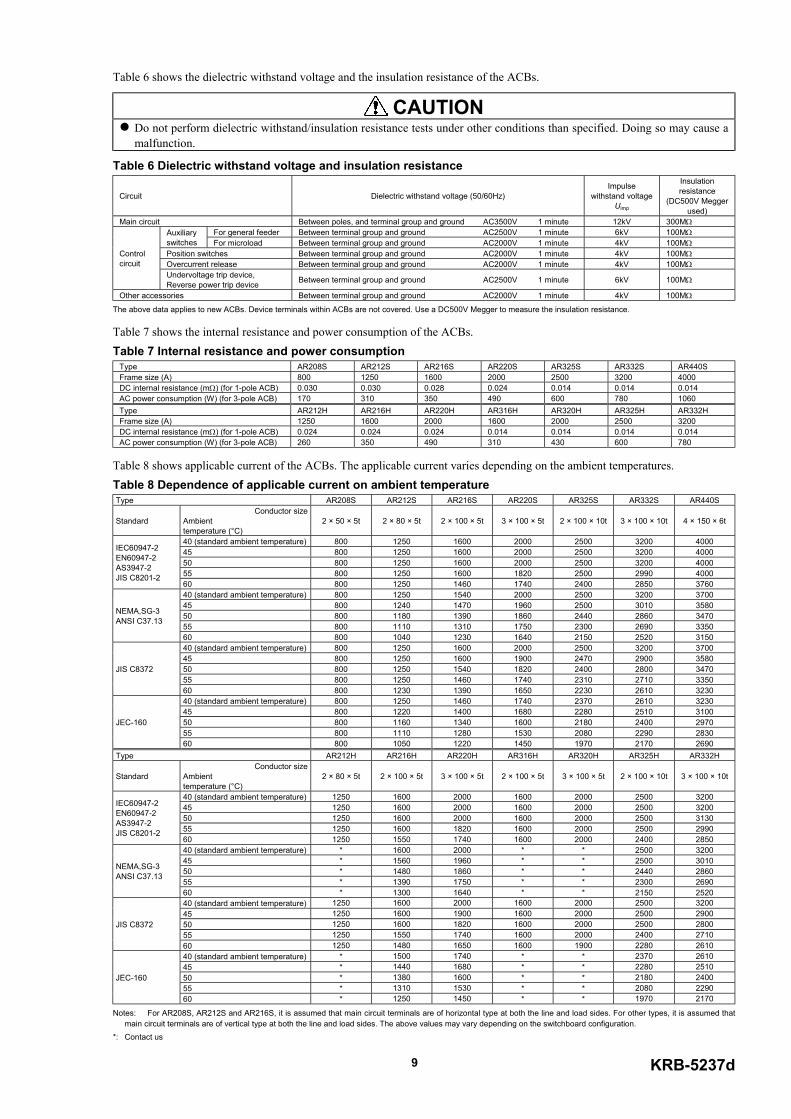
Table 8 shows applicable current of the ACBs. The applicable current varies depending on the ambient temperatures.Table 8 Dependence of applicable current on ambient temperatureType AR208S AR212S AR216S AR220S AR325S AR332S AR440S
StandardConductor size
Ambient temperature (°C)
2 × 50 × 5t 2 × 80 × 5t 2 × 100 × 5t 3 × 100 × 5t 2 × 100 × 10t 3 × 100 × 10t 4 × 150 × 6t
40 (standard ambient temperature) 800 1250 1600 2000 2500 3200 400045 800 1250 1600 2000 2500 3200 400050 800 1250 1600 2000 2500 3200 400055 800 1250 1600 1820 2500 2990 4000
IEC60947-2EN60947-2AS3947-2JIS C8201-2
60 800 1250 1460 1740 2400 2850 376040 (standard ambient temperature) 800 1250 1540 2000 2500 3200 370045 800 1240 1470 1960 2500 3010 358050 800 1180 1390 1860 2440 2860 347055 800 1110 1310 1750 2300 2690 3350
NEMA,SG-3ANSI C37.13
60 800 1040 1230 1640 2150 2520 315040 (standard ambient temperature) 800 1250 1600 2000 2500 3200 370045 800 1250 1600 1900 2470 2900 358050 800 1250 1540 1820 2400 2800 347055 800 1250 1460 1740 2310 2710 3350
JIS C8372
60 800 1230 1390 1650 2230 2610 323040 (standard ambient temperature) 800 1250 1460 1740 2370 2610 323045 800 1220 1400 1680 2280 2510 310050 800 1160 1340 1600 2180 2400 297055 800 1110 1280 1530 2080 2290 2830
JEC-160
60 800 1050 1220 1450 1970 2170 2690Type AR212H AR216H AR220H AR316H AR320H AR325H AR332H
StandardConductor size
Ambient temperature (°C)
2 × 80 × 5t 2 × 100 × 5t 3 × 100 × 5t 2 × 100 × 5t 3 × 100 × 5t 2 × 100 × 10t 3 × 100 × 10t
40 (standard ambient temperature) 1250 1600 2000 1600 2000 2500 320045 1250 1600 2000 1600 2000 2500 320050 1250 1600 2000 1600 2000 2500 313055 1250 1600 1820 1600 2000 2500 2990
IEC60947-2EN60947-2AS3947-2JIS C8201-2
60 1250 1550 1740 1600 2000 2400 285040 (standard ambient temperature) * 1600 2000 * * 2500 320045 * 1560 1960 * * 2500 301050 * 1480 1860 * * 2440 286055 * 1390 1750 * * 2300 2690
NEMA,SG-3ANSI C37.13
60 * 1300 1640 * * 2150 252040 (standard ambient temperature) 1250 1600 2000 1600 2000 2500 320045 1250 1600 1900 1600 2000 2500 290050 1250 1600 1820 1600 2000 2500 280055 1250 1550 1740 1600 2000 2400 2710
JIS C8372
60 1250 1480 1650 1600 1900 2280 261040 (standard ambient temperature) * 1500 1740 * * 2370 261045 * 1440 1680 * * 2280 251050 * 1380 1600 * * 2180 240055 * 1310 1530 * * 2080 2290
JEC-160
60 * 1250 1450 * * 1970 2170
Notes: For AR208S, AR212S and AR216S, it is assumed that main circuit terminals are of horizontal type at both the line and load sides. For other types, it is assumed thatmain circuit terminals are of vertical type at both the line and load sides. The above values may vary depending on the switchboard configuration.
*: Contact us
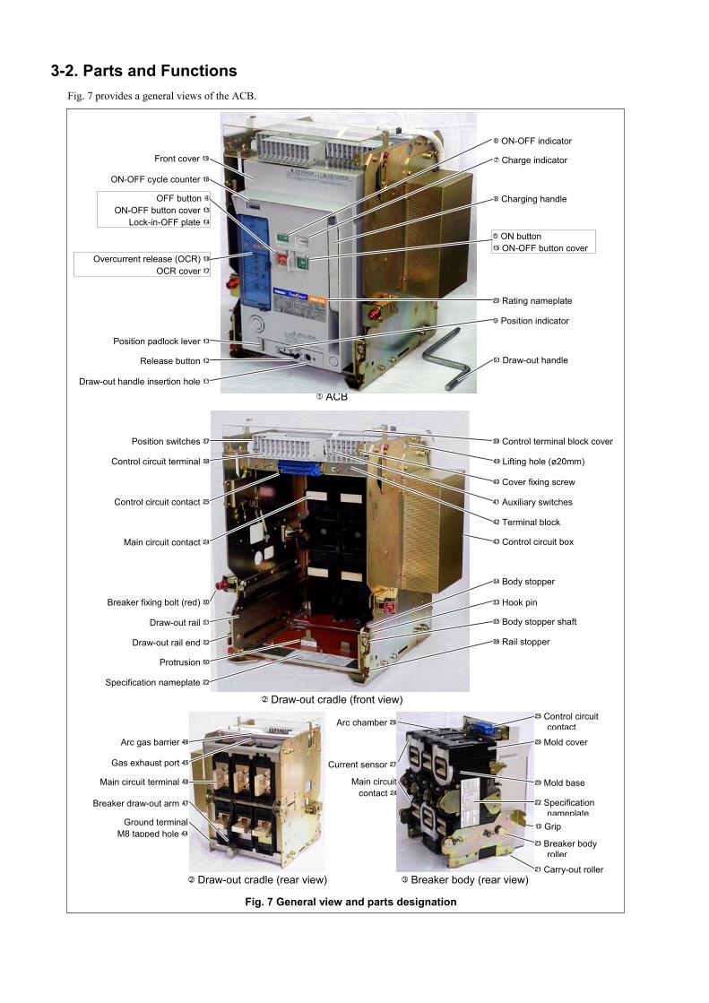
3-2. Parts and FunctionsFig. 7 provides a general views of the ACB.
OFF button 4ON-OFF button cover 15
Lock-in-OFF plate 14
5 ON button15 ON-OFF button cover
6 ON-OFF indicator
7 Charge indicator
8 Charging handle
9 Position indicator
Draw-out handle insertion hole 11
Release button 12
Position padlock lever 13
ON-OFF cycle counter 16
Overcurrent release (OCR) 18
OCR cover 17
Front cover 19
20 Rating nameplate
51 Draw-out handle
Ground terminalM8 tapped hole 44
Gas exhaust port 45
Arc gas barrier 46
Breaker draw-out arm 47
Main circuit terminal 48
Breaker fixing bolt (red) 30
Draw-out rail 31
Draw-out rail end 32
33 Hook pin
34 Body stopper
35 Body stopper shaft
36 Rail stopper
Position switches 37
Control circuit terminal 38
39 Control terminal block cover
41 Auxiliary switches
42 Terminal block
49 Lifting hole (ø20mm)
Specification nameplate 22
Main circuit contact 24
Control circuit contact 25
Protrusion 50
40 Cover fixing screw
43 Control circuit box
28 Mold cover
29 Mold base
10 Grip
23 Breaker bodyroller
25 Control circuitcontact
21 Carry-out roller
Main circuitcontact 24
Arc chamber 26
Current sensor 27
2 Draw-out cradle (rear view)
2 Draw-out cradle (front view)
22 Specificationnameplate
3 Breaker body (rear view)
1 ACB
Fig. 7 General view and parts designation
KRB-5237d11
1 ACB Consists of breaker body 3 and draw-out cradle 2 .
2 Draw-out cradle Comes with main circuit terminals 48 , control circuit terminals 38 , auxiliary switches 41 , and position
switches 37 .
3 Breaker body Contains the ON-OFF mechanism, the closing coil,the tripping device, and overcurrent release 19 .
4 OFF button Push to open the ACB.
5 ON button Push to close the ACB.
6 ON-OFF indicator Shows “OFF” when the ACB is open and “ON” when it is closed.
7 Charge indicator Shows “CHARGED” when the closing springs are charged and “DISCHARGED” when it is released.
8 Charging handle Pump to charge the closing springs.
9 Position indicator Indicates the present breaker body position: CONN., TEST, or ISOLATED.
10 Grip Hold to draw out the breaker body.
11 Draw-out handle insertion hole Insert the draw-out handle into this hole to move the breaker body.
12 Release button Push to move the breaker body from the TEST position.
13 Position padlock lever (optional) Accommodates up to three padlocks to lock the breaker body in the CONN., TEST or
ISOLATED position. (Padlocks are not supplied. Use padlocks with a 6 mm-diameter shackle.)
14 Lock-in-OFF plate Padlocking this plate allows the ACB to be locked in the open (OFF) state. (Padlocks are not supplied.
Use padlocks with a 6 mm-diameter shackle.)
15 ON-OFF button cover Provides protection against inadvertent button operation and can be padlocked. (Padlocks are not
supplied. Use padlocks with a 6 mm-diameter shackle.) Up to three padlocks can be installed.
16 ON-OFF cycle counter (optional) Reads the number of ON-OFF cycles. It counts a series of operations from close to open
as one cycle.
17 OCR cover Padlocking this plate prevents settings of overcurrent release 18 to be inadvertently changed. (Padlocks are not
supplied. Use padlocks with a 6 mm-diameter shackle.)
18 Overcurrent release (OCR) This protective device is supplied power via the power CT installed in the ACB main circuit.
When the current sensor detects an overcurrent in the main circuit, the OCR instructs the magnet hold trigger (MHT) to trip
open the ACB.
19 Front cover A plastic cover of the breaker body front panel.
20 Rating nameplate Indicates the type, applicable standards and rated breaking capacity of the ACB.
21 Carry-out roller (optional) Allows the breaker body 3 to be moved on a floor.
22 Specification nameplate Indicates the number of poles, operation method, accessories, and serial number of the ACB.
23 Breaker body roller Allows breaker body 3 to be moved on draw-out rail 31 .
24 Main circuit contact Closes when the breaker body is in the CONN. position.
25 Control circuit contact Closes when the breaker body is in the CONN. or TEST position.
26 Arc chamber Extinguishes the arc that occurs in the breaking operation.
27 Current sensor Converts the current in the main circuit into a voltage signal in proportion to the magnitude of the current
and sends the signal to overcurrent release 18 .
28 Mold cover A plastic cover of the breaker body side face.
29 Mold base A plastic cover of the breaker body rear face.
30 Breaker fixing bolt (red) (optional) Allows the breaker body to be locked in the CONN. position even if the ACB is
subject to strong vibrations.
31 Draw-out rail Use to draw out the breaker body from the draw-out cradle.
32 Draw-out rail end Refer to chapter 1 “Operation Precautions”.
33 Hook pin Refer to chapter 1 “Operation Precautions”.
34 Body stopper Prevents the breaker body from falling when the body is drawn out from the draw-out cradle.
35 Body stopper shaft Refer to chapter 1 “Operation Precautions”.
36 Rail stopper (red) Allows the draw-out rail to be locked in the drawn-out or retracted state.
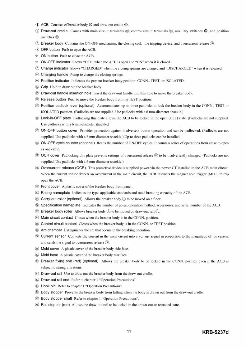
37 Position switches (optional) Indicate the present breaker body position: CONN., TEST, ISOLATED or INSERTED. The
position switches are available in 2C or 4C configuration. Connections to the position switches are made through #187 plug-
in tab terminals (standard) or M4 screws.
38 Control circuit terminals Allow connections of external control wire to the control circuits. Wire connections are made
through #187 plug-in tab terminals (standard) or M4 screw terminals. Fig. 8 shows the #187 tab terminals and M4 screws
terminals.
39 Control terminal block cover (optional) Protects the position switches, the control circuit terminals and the auxiliary
switches from damage.
40 Cover fixing screw Secures the control terminal block cover.
41 Auxiliary switches (optional) Indicate the state of the ACB (ON or OFF). The auxiliary switches are available in 4C
configuration (standard), or 7C or 10C configuration (optional). Connections to the switches are made through #187 plug-in
tab terminals (standard) or M4 screw terminals.
42 Terminal block Contains position switches 36 , control circuit terminals 37 , and auxiliary switches 38 .
43 Control circuit box Is accompanied by an optional fixed-type undervoltage trip device.
44 Ground terminal M8 tapped hole Allows connection of a ground terminal.
45 Gas exhaust port Allows the arc gas to be discharged from arc chamber 25 in a horizontal direction when the ACB trips
open.
46 Arc gas barrier Prevents the arc gas from being discharged upwards from arc chamber 25 when the ACB trips open.
47 Breaker draw-out arm Is retracted in the draw-out cradle when the breaker body is in the CONN. position.
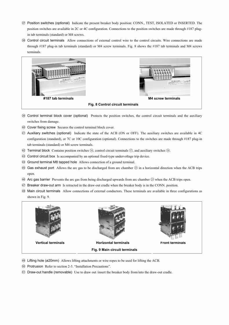
48 Main circuit terminals Allow connections of external conductors. These terminals are available in three configurations as
shown in Fig. 9.
49 Lifting hole (ø20mm) Allows lifting attachments or wire ropes to be used for lifting the ACB.
50 Protrusion Refer to section 2-3. “Installation Precautions”.
51 Draw-out handle (removable) Use to draw out /insert the breaker body from/into the draw-out cradle.
#187 tab terminals M4 screw terminalsFig. 8 Control circuit terminals
Vertical terminals Horizontal terminals Front terminals
Fig. 9 Main circuit terminals

KRB-5237d13
3-3. Circuits and RatingsFig. 10 shows an ACB circuit diagram and Table 9 and Fig. 11 show the function of each terminal and the meaning of each sign
in the diagram.
Table 9 Terminal functions and circuit symbols (Applicable to both 50 and 60Hz for AC. + and – mean the polarity for DC)Terminal No. Function
01 , 11 AC100 - 120V11+ , 21– DC100 - 125V or DC24V01+ , 21– AC200 - 240V, DC200 - 250V or DC48V
Control power input terminals
02+ , 22– AC100 - 120V, AC200 - 240V, DC100 - 125V, DC200 - 250V, DC24V or DC48V Operation power input terminals03 , 12 ON switch Operation switch terminals05 , 15 Group indication or long time delay (LT) operation indication05 , 25 Short time delay (ST) and instantaneous trip (INST/MCR) operation indication05 , 06 One-step pretrip alarm (PTA) indication05 , 16 Ground fault trip (GF) indication05 , 26 System alarm indication05 , 17 Trip indication05 , 27 Spring charged indication
Operation indication contact outputterminals
10 , 20 AC100V, AC110V, AC120V, AC200V, AC220V, AC240V, DC24V, DC48V, DC100V, DC110V, DC125V, DC200V or DC220V Shunt trip device power input terminals
Terminal No. AC100V coil AC200V coil AC400V coil08 , 09 100V 200V 380V18 , 09 110V 220V 415V28 , 09 120V 240V 440V
08 , 09 , 18 , 28 Fixed type undervoltage trip devicepower input terminals
24 , 30 OFF switch Fixed type undervoltage trip19 , 29 Polarity: 19 - , 29 - N-phase CT connection terminals *304 , 07 , 13 , 14 , 23 — (Reserved)
Symbol Meaning Symbol MeaningM Spring charging motor CT1 - CT3 Power supply CT *7LRC Latch release coil Main/control circuit contactMHT Magnet hold trigger Hand connectorSHT Shunt trip device User wiringUVT Fixed type undervoltage trip device Relay or LEDS1 - S4 Current sensors *6
*1: For 4-pole ACBs. *2: For 4-pole ACBs equipped with N-phase protection and/or ground fault trip functions. *3: Used for 3-pole ACBs with N-phase protection and/or ground fault trip functions to be installed in a 3-phase, 43-wire circuit. *4: Do not connect the ON switch with auxiliary switch b-contact in series. Doing so may cause pumping. *5: Use auxiliary switch a-contact. *6: Conversion ratio: CT rated primary current ICT (A)/150 mV*7: Provide power to the overcurrent trip device when control power is lost.
Fig. 10 Breaker circuits
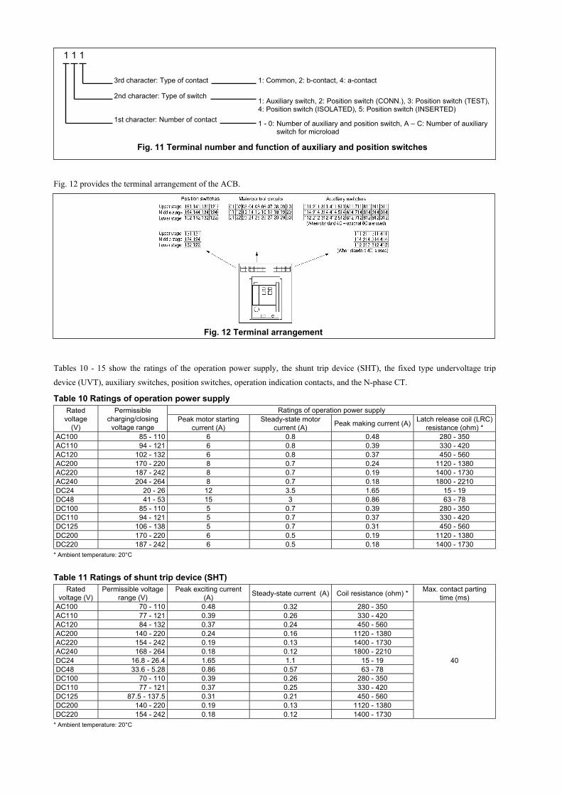
Fig. 12 provides the terminal arrangement of the ACB.
Tables 10 - 15 show the ratings of the operation power supply, the shunt trip device (SHT), the fixed type undervoltage trip
device (UVT), auxiliary switches, position switches, operation indication contacts, and the N-phase CT.
Table 10 Ratings of operation power supplyRatings of operation power supplyRated
voltage(V)
Permissiblecharging/closing
voltage rangePeak motor starting
current (A)Steady-state motor
current (A) Peak making current (A) Latch release coil (LRC)resistance (ohm) *
AC100 85 - 110 6 0.8 0.48 280 - 350AC110 94 - 121 6 0.8 0.39 330 - 420AC120 102 - 132 6 0.8 0.37 450 - 560AC200 170 - 220 8 0.7 0.24 1120 - 1380AC220 187 - 242 8 0.7 0.19 1400 - 1730AC240 204 - 264 8 0.7 0.18 1800 - 2210DC24 20 - 26 12 3.5 1.65 15 - 19DC48 41 - 53 15 3 0.86 63 - 78DC100 85 - 110 5 0.7 0.39 280 - 350DC110 94 - 121 5 0.7 0.37 330 - 420DC125 106 - 138 5 0.7 0.31 450 - 560DC200 170 - 220 6 0.5 0.19 1120 - 1380DC220 187 - 242 6 0.5 0.18 1400 - 1730
* Ambient temperature: 20°C
Table 11 Ratings of shunt trip device (SHT)Rated
voltage (V)Permissible voltage
range (V)Peak exciting current
(A) Steady-state current (A) Coil resistance (ohm) * Max. contact partingtime (ms)
AC100 70 - 110 0.48 0.32 280 - 350AC110 77 - 121 0.39 0.26 330 - 420AC120 84 - 132 0.37 0.24 450 - 560AC200 140 - 220 0.24 0.16 1120 - 1380AC220 154 - 242 0.19 0.13 1400 - 1730AC240 168 - 264 0.18 0.12 1800 - 2210DC24 16.8 - 26.4 1.65 1.1 15 - 19DC48 33.6 - 5.28 0.86 0.57 63 - 78DC100 70 - 110 0.39 0.26 280 - 350DC110 77 - 121 0.37 0.25 330 - 420DC125 87.5 - 137.5 0.31 0.21 450 - 560DC200 140 - 220 0.19 0.13 1120 - 1380DC220 154 - 242 0.18 0.12 1400 - 1730
40
* Ambient temperature: 20°C
3rd character: Type of contact
2nd character: Type of switch
1st character: Number of contact
1 1 1
1: Common, 2: b-contact, 4: a-contact
1: Auxiliary switch, 2: Position switch (CONN.), 3: Position switch (TEST),4: Position switch (ISOLATED), 5: Position switch (INSERTED)
1 - 0: Number of auxiliary and position switch, A – C: Number of auxiliaryswitch for microload
Fig. 11 Terminal number and function of auxiliary and position switches
Fig. 12 Terminal arrangement
KRB-5237d15
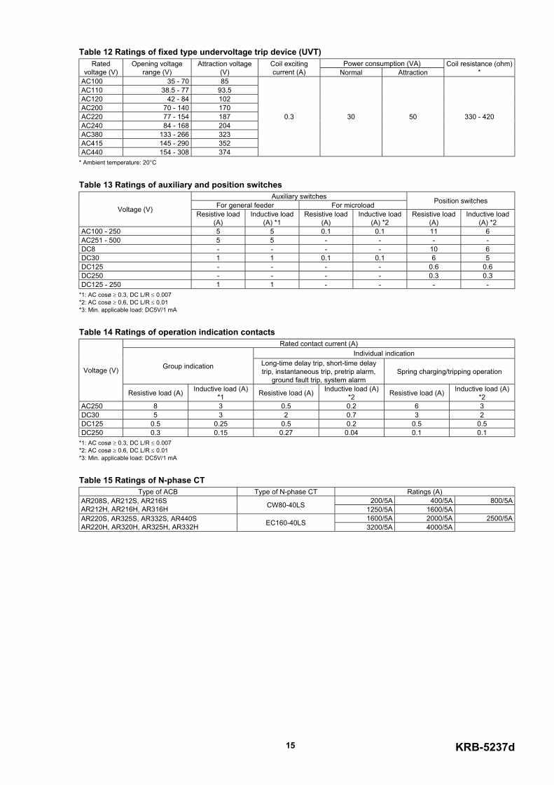
Table 12 Ratings of fixed type undervoltage trip device (UVT)Power consumption (VA)Rated
voltage (V)Opening voltage
range (V)Attraction voltage
(V)Coil excitingcurrent (A) Normal Attraction
Coil resistance (ohm)*
AC100 35 - 70 85AC110 38.5 - 77 93.5AC120 42 - 84 102AC200 70 - 140 170AC220 77 - 154 187AC240 84 - 168 204AC380 133 - 266 323AC415 145 - 290 352AC440 154 - 308 374
0.3 30 50 330 - 420
* Ambient temperature: 20°C
Table 13 Ratings of auxiliary and position switchesAuxiliary switches
For general feeder For microload Position switchesVoltage (V) Resistive load
(A)Inductive load
(A) *1Resistive load
(A)Inductive load
(A) *2Resistive load
(A)Inductive load
(A) *2AC100 - 250 5 5 0.1 0.1 11 6AC251 - 500 5 5 - - - -DC8 - - - - 10 6DC30 1 1 0.1 0.1 6 5DC125 - - - - 0.6 0.6DC250 - - - - 0.3 0.3DC125 - 250 1 1 - - - -
*1: AC cosø ≥ 0.3, DC L/R ≤ 0.007*2: AC cosø ≥ 0.6, DC L/R ≤ 0.01*3: Min. applicable load: DC5V/1 mA
Table 14 Ratings of operation indication contactsRated contact current (A)
Individual indication
Group indication Long-time delay trip, short-time delaytrip, instantaneous trip, pretrip alarm,
ground fault trip, system alarmSpring charging/tripping operationVoltage (V)
Resistive load (A) Inductive load (A)*1 Resistive load (A) Inductive load (A)
*2 Resistive load (A) Inductive load (A)*2
AC250 8 3 0.5 0.2 6 3DC30 5 3 2 0.7 3 2DC125 0.5 0.25 0.5 0.2 0.5 0.5DC250 0.3 0.15 0.27 0.04 0.1 0.1
*1: AC cosø ≥ 0.3, DC L/R ≤ 0.007*2: AC cosø ≥ 0.6, DC L/R ≤ 0.01*3: Min. applicable load: DC5V/1 mA
Table 15 Ratings of N-phase CTType of ACB Type of N-phase CT Ratings (A)
200/5A 400/5A 800/5AAR208S, AR212S, AR216SAR212H, AR216H, AR316H CW80-40LS 1250/5A 1600/5A
1600/5A 2000/5A 2500/5AAR220S, AR325S, AR332S, AR440SAR220H, AR320H, AR325H, AR332H EC160-40LS 3200/5A 4000/5A
4. OPERATION4-1. Charging and Opening operation
DANGER Never touch live terminal parts. Otherwise, electric shock may result.
CAUTION Do not force down the charging handle after completion of manual charging operation. Doing so may cause a malfunction. The permissible operating voltage of the spring charging motor is 85 to 110% of the rated ac voltage or 75 to 110% of therated dc voltage. Be sure to supply a voltage within the above ranges to the motor. Otherwise, burnout may result.
Repeated open/close operation by the motor charging mechanism without pause should not exceed 15 times. If repeatedcontinuous open/close operation is inevitable, a pause of at least 20 minutes should be provided after the repetitions of 15times. Otherwise, a spring charging motor may be burnt out.
Do not bring your hand or face close to arc gas vent of the arc chamber while the ACB is energized. Otherwise, a burn mayresult from high-temperature arc gas blowing out of the arc gas vent when the ACB trips open.
If the ACB trips open automatically, remove the cause of tripping operation before re-closing the ACB. Otherwise, a firecould result.
If the ACB has the breaker fixing bolts, make sure the bolts on both sides are securely tightened before using the ACB.Loosened fixing bolts may cause a malfunction of the ACB, in particular when it is installed in such an area that is subjectto strong vibrations.
The ACBs are available in two types in terms of the closing spring charging method and the remote operation capability: a
manual charging type and a motor charging type. The manual charging type requires the charging and ON-OFF (close/open)
operation to be done manually while the motor charging type allows the operation to be done either manually or by using a
motor.
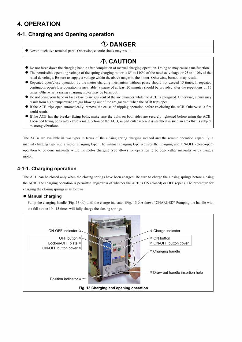
4-1-1. Charging operationThe ACB can be closed only when the closing springs have been charged. Be sure to charge the closing springs before closing
the ACB. The charging operation is permitted, regardless of whether the ACB is ON (closed) or OFF (open). The procedure for
charging the closing springs is as follows:
Manual chargingPump the charging handle (Fig. 13 2 ) until the charge indicator (Fig. 13 1 ) shows “CHARGED” Pumping the handle with
the full stroke 10 - 13 times will fully charge the closing springs.
1 Charge indicator
2 Charging handle
Position indicator 35 Draw-out handle insertion hole
9 ON button8 ON-OFF button cover
ON-OFF indicator 10
OFF button 6Lock-in-OFF plate 7
ON-OFF button cover 8
Fig. 13 Charging and opening operation
KRB-5237d17
Motor chargingWhen the charge indicator (Fig. 13 1 ) changes to “DISCHARGED” while the specified operation voltage is applied to the
control circuit terminals 02 and 22 , the charging motor is activated to start charging the closing springs. Upon completion of
the charging operation, the charge indicator shows “CHARGED” and the charging motor is automatically deactivated. The
time required for the motor charging operation depends on the operation voltage or the ACB types, but does not exceed 10
seconds.
4-1-2. Closing operationThe ACB closing operation is not permitted unless all of the following conditions are met.
1) The charge indicator (Fig. 13 1 ) shows "CHARGED".
2) The position indicator (Fig.13 3 ) shows "CONN.", "TEST" or "ISOLATED".
3) The draw-out handle is not inserted in the draw-out handle insertion hole(Fig.13 5 ) .
4) The OFF button (Fig. 13 6 ) is not locked with the lock-in-OFF plate (Fig. 13 7 ).
5) The specified voltage is supplied to the undervoltage trip device .
Manual closingOpen the ON-OFF button cover (Fig.13 8 ) and press the ON button (Fig.13 9 ). The ACB will be closed with a sound. The
ON-OFF indicator (Fig. 13 10 ) shows "ON" and the charge indicator (Fig. 13 1 ) shows "DISCHARGED".
Electrical closingPress the ON switch shown in Fig. 10. The latch release coil (LRC) (Fig. 10) will be excited and the ACB is closed with a
sound. The ON-OFF indicator (Fig. 13 10 ) shows "ON", the charge indicator (Fig. 13 1 ) shows "DISCHARGED", and the
charging motor starts charging the closing springs.
4-1-3. Opening operation
Manual openingOpen the ON-OFF button cover (Fig. 13 8 ) and press the OFF button (Fig. 13 16 ). The ACB will trip open with a sound. The
ON-OFF indicator (Fig.13 10 ) shows "OFF".
Electrical openingPress the OFF switch shown in Fig. 10. The shunt trip device (SHT) or the fixed type undervoltage trip device (Fig. 10) will
be excited so that the ACB trips open with a sound. The ON-OFF indicator (Fig.13 10 ) shows "OFF".
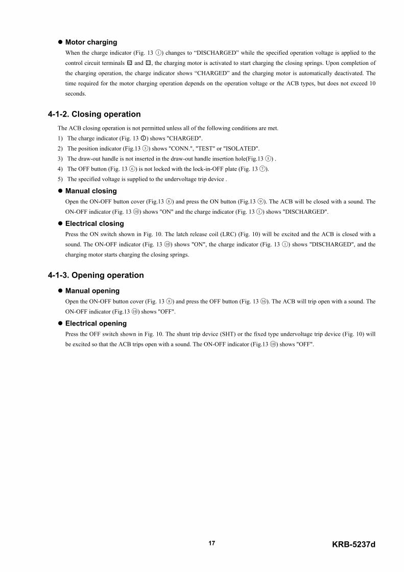
4-1-4. Motion of operation mechanismsFigs. 14 - 17 illustrate the motion of the charging and ON-OFF mechanisms.
1 '
21
4
5
6
7
8
3
For manual closing operation, ON button 1 rotatescounterclockwise. For electrical closing operation, pushrod 1 ' protrudes downward from the latch release coil(LRC) and charge latch trigger 2 rotates clockwise. Thisrotates closing trigger shaft 3 clockwise and closingrelease lever 4 disengages from a semicircular pawl androtates clockwise. And charging cam 5 rotatescounterclockwise, so that charging lever 7 disengagesfrom closing spring 6 and rotates counterclockwise.Closing cam 8 is pushed up by charging lever 7 androtates clockwise. At this time, each component ispositioned as shown in Fig. 16. Continued to Fig. 15.
Fig. 14 Closing motion 1 (discharge motion)
Closing cam 8 rotating clockwise causes closing linkand top link 9 to be pushed straight. This rotates closingtoggle cam 10 connected with closing link 9counterclockwise, so that crossbar 11 rotates clockwiseand thus moving contact 12 comes in contact withstationary contact 13. At this time, each component ispositioned as shown in Fig. 17.
1011
12
98
13
13
Fig. 15 Closing motion 2

KRB-5237d19
Fig. 16 Charging motion
The charging handle or the charging motor provides acounterclockwise rotation to charging cam 1 . This rotatesclosing release lever 2 and closing tripper lever 3counterclockwise and a semicircular pawl engages withclosing release lever 2 . And charging lever 4 rotatesclockwise so that closing spring 5 is compressed andclosing cam 5 rotates counterclockwise. At this time, eachcomponent is positioned as shown in Fig. 14.
1
4
2
3
65
For manual opening operation, OFF button 1 rotatescounterclockwise and trip linkage 2 rotates clockwise. Forelectrical opening operation, push rod 1 protrudesdownward from the shunt trip device (SHT) or the fixedtype undervoltage trip device (UVT). For trippingoperation by the overcurrent release (OCR), moving core1 protrudes downward from the magnet hold trigger(MHT) and trip linkage 2 rotates counterclockwise. (Partsmarked with an asterisk (*) are trip pins. To avoidsuperposition in the figure, magnet hold trigger relatedparts are drawn in positions that are different from actualpositions. This rotates trip trigger shaft 3counterclockwise and trip lever B 4 disengages from asemicircular pawl and rotates counterclockwise. And triplever A 5 rotates counterclockwise, trip link 6 moves to alower right direction and closing toggle cam 7 rotatesclockwise. The force of closing spring 9 and contactspring 10 rotates crossbar 8 counterclockwise, so thatmoving contact 10 is parted from stationary contact 12. Atthis time, each component is positioned as shown in Fig.15.
1 "2 "
3
45
6
7
8
11
1 '
12
*
9
10
10
12
Fig. 17 Opening motion
12
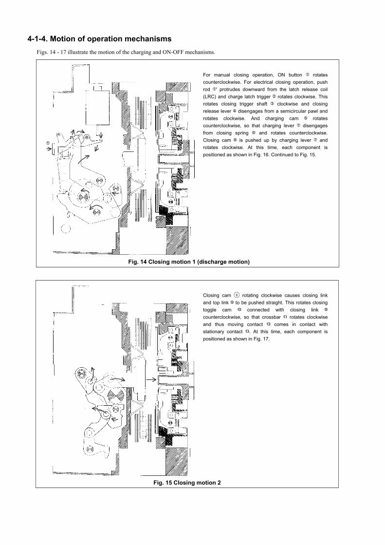
4-2. Draw-out and Insertion Operation4-2-1. General
The draw-out type ACB consists of the breaker body and the draw-out cradle. The main and control circuit terminals are installed
on the draw-out cradle, which permits you to draw out and inspect or service the breaker body without the need for removing
wiring from the terminals.
The draw-out mechanism allows you to move the breaker body to any of the four positions as shown in Fig. 18. The switchboard
panel door can be shut with the breaker body drawn out to the CONN., TEST or ISOLATED position.
Draw-out
Breaker body Control circuitcontact
Draw-out cradleControl circuitcontact
Rollers Draw-out rail
1. CONN. position 4. Removed position
2. TEST position 3. ISOLATED position
Position indicator Position indicator
Position indicator Position indicator
In this position, the main circuit and the controlcircuits of the ACB are connected to the externalcircuits for normal service.
In this position, the main circuit is isolated, and thecontrol circuits are connected. The ACB can betested with the switchboard panel door closed.
The breaker body is removed from the draw-outcradle.
In this position, both the main and control circuitsare isolated, and the ACB is completely de-energized. The switchboard panel door can beclosed.
Insert Insert Draw-out
Insert
Draw-out
Fig. 18 Positions of breaker body in draw-out cradle
KRB-5237d21
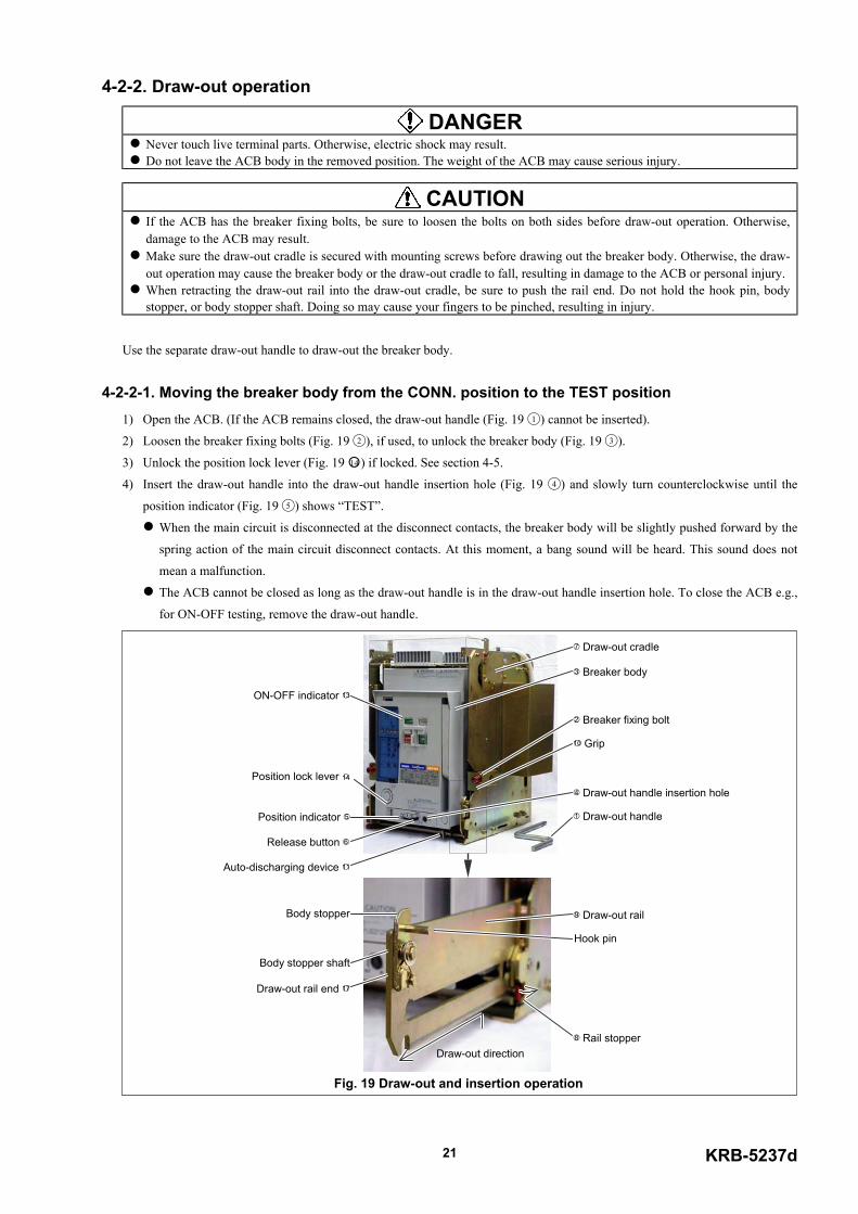
4-2-2. Draw-out operation
DANGER Never touch live terminal parts. Otherwise, electric shock may result. Do not leave the ACB body in the removed position. The weight of the ACB may cause serious injury.
CAUTION If the ACB has the breaker fixing bolts, be sure to loosen the bolts on both sides before draw-out operation. Otherwise,damage to the ACB may result.
Make sure the draw-out cradle is secured with mounting screws before drawing out the breaker body. Otherwise, the draw-out operation may cause the breaker body or the draw-out cradle to fall, resulting in damage to the ACB or personal injury.
When retracting the draw-out rail into the draw-out cradle, be sure to push the rail end. Do not hold the hook pin, bodystopper, or body stopper shaft. Doing so may cause your fingers to be pinched, resulting in injury.
Use the separate draw-out handle to draw-out the breaker body.
4-2-2-1. Moving the breaker body from the CONN. position to the TEST position1) Open the ACB. (If the ACB remains closed, the draw-out handle (Fig. 19 1 ) cannot be inserted).
2) Loosen the breaker fixing bolts (Fig. 19 2 ), if used, to unlock the breaker body (Fig. 19 3 ).
3) Unlock the position lock lever (Fig. 19 14 ) if locked. See section 4-5.
4) Insert the draw-out handle into the draw-out handle insertion hole (Fig. 19 4 ) and slowly turn counterclockwise until the
position indicator (Fig. 19 5 ) shows “TEST”.
When the main circuit is disconnected at the disconnect contacts, the breaker body will be slightly pushed forward by the
spring action of the main circuit disconnect contacts. At this moment, a bang sound will be heard. This sound does not
mean a malfunction.
The ACB cannot be closed as long as the draw-out handle is in the draw-out handle insertion hole. To close the ACB e.g.,
for ON-OFF testing, remove the draw-out handle.
Fig. 19 Draw-out and insertion operation
1 Draw-out handle
3 Breaker body
4 Draw-out handle insertion hole
Position indicator 5
Release button 6
7 Draw-out cradle
10 Grip
Auto-discharging device 11
ON-OFF indicator 13
2 Breaker fixing bolt
8 Rail stopper
9 Draw-out rail
Draw-out rail end 17
Body stopper
Hook pin
Body stopper shaft
Draw-out direction
Position lock lever 14
4-2-2-2. Moving the breaker body from the TEST position to the ISOLATED position1) Open the ACB. (If the ACB remains closed, the draw-out handle (Fig. 19 1 ) cannot be inserted).
2) Press the release button (Fig. 19 6 ). The release button will be locked depressed.
3) Unlock the position lock lever (Fig. 19 14 ) if locked. See section 4-5.
4) Insert the draw-out handle into the draw-out handle insertion hole (Fig. 19 4 ) and slowly turn counterclockwise until the
position indicator (Fig. 19 5 ) shows “ISOLATED” and a freewheeling sound is heard. Turning the draw-out handle will
unlock the release button.
5) Remove the draw-out handle.
4-2-2-3. Moving the breaker body from the ISOLATED position to the removed position1) Make sure the draw-out cradle (Fig. 19 7 ) is secured with mounting screws.
2) Unlock the position lock lever (Fig. 19 14 ) if locked. See section 4-5.
3) Push the rail stoppers (Fig. 19 8 ) outward on both sides of the draw-out cradle to unlock the draw-out rail (Fig. 19 9 ), and
then uphold and pull out the rail until it stops. The draw-out rail will be locked again by the stoppers. (The breaker body
cannot be drawn out unless the rail is locked).
4) Holding both the grips (Fig. 19 10 ), draw out the breaker body until it stops.
If the ACB is equipped with an optional auto-discharging device (Fig. 19 11 ), the closing springs of the ACB will be
automatically discharged with a mechanical sound. This sound does not mean a malfunction.
Do not leave the ACB body on the draw-out rail pulled out.
5) Use an optional lifter or lifting plate to transfer the breaker body (Fig. 19 3 ) to a safe place. Refer to section 2-1-2.
4-2-3. Putting the breaker body back into the draw-out cradle
DANGER Never touch live terminal parts. Otherwise, electric shock may result. Do not leave the ACB body in the removed position. The weight of the ACB may cause serious injury.
CAUTION Make sure the draw-out cradle is secured with mounting screws before inserting the breaker body into the draw-out cradle.Otherwise, the insertion operation may cause the breaker body or the draw-out cradle to fall, resulting in damage to theACB or personal injury.
When retracting the draw-out rail into the draw-out cradle, be sure to push the rail end. Do not hold the hook pin, bodystopper, or body stopper shaft. Doing so may cause your fingers to be pinched, resulting in injury.
Do not forcedly turn the draw-out handle clockwise when the breaker body is in the CONN. Position. Doing so may causea malfunction.
If the ACB has the breaker fixing bolts, make sure the bolts on both sides are securely tightened before using the ACB.Loosened fixing bolts may cause a malfunction of the ACB, in particular when it is installed in such an area that is subjectto strong vibrations.
Use the separate draw-out handle to insert the breaker body.
4-2-3-1. Putting the breaker body back to the ISOLATED position1) Make sure the draw-out cradle (Fig. 19 7 ) is secured with mounting screws.
2) Push the rail stoppers (Fig. 19 8 ) outward on both sides of the draw-out cradle to unlock the draw-out rail (Fig. 19 9 ), and
then uphold and pull out the rail until it stops. The draw-out rail will be locked again by the stoppers. (The breaker body (Fig.
19 3 ) cannot be inserted unless the rail is locked).
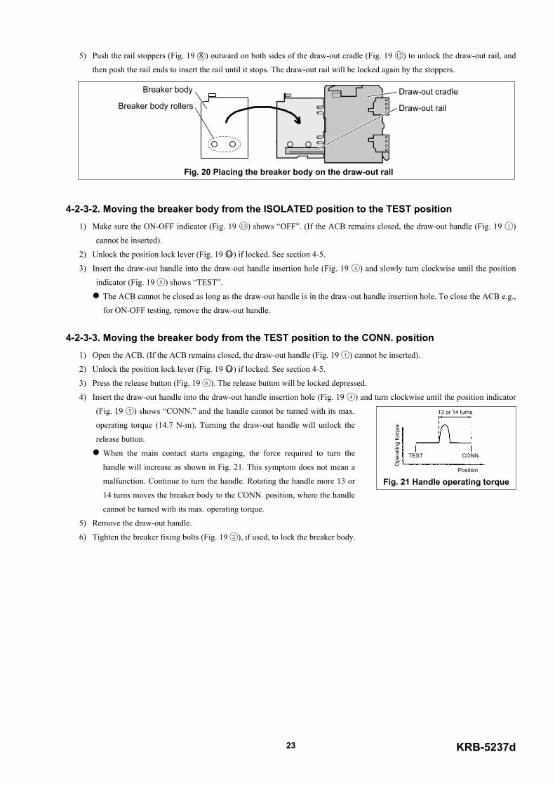
3) Use an optional lifter or lifting plate to place the breaker body rollers (Fig. 20) on the draw-out rail (Fig. 20).
Do not leave the ACB body on the draw-out rail pulled out.
4) If the ACB has the breaker fixing bolts (Fig. 19 2 ), make sure the bolts are loosened and, holding both the grips (Fig. 19 10 ),
firmly push the breaker body into the draw-out cradle.
KRB-5237d23
5) Push the rail stoppers (Fig. 19 8 ) outward on both sides of the draw-out cradle (Fig. 19 12 ) to unlock the draw-out rail, and
then push the rail ends to insert the rail until it stops. The draw-out rail will be locked again by the stoppers.
4-2-3-2. Moving the breaker body from the ISOLATED position to the TEST position1) Make sure the ON-OFF indicator (Fig. 19 13 ) shows “OFF”. (If the ACB remains closed, the draw-out handle (Fig. 19 1 )
cannot be inserted).
2) Unlock the position lock lever (Fig. 19 14 ) if locked. See section 4-5.
3) Insert the draw-out handle into the draw-out handle insertion hole (Fig. 19 4 ) and slowly turn clockwise until the position
indicator (Fig. 19 5 ) shows “TEST”.
The ACB cannot be closed as long as the draw-out handle is in the draw-out handle insertion hole. To close the ACB e.g.,
for ON-OFF testing, remove the draw-out handle.
4-2-3-3. Moving the breaker body from the TEST position to the CONN. position1) Open the ACB. (If the ACB remains closed, the draw-out handle (Fig. 19 1 ) cannot be inserted).
2) Unlock the position lock lever (Fig. 19 14 ) if locked. See section 4-5.
3) Press the release button (Fig. 19 6 ). The release button will be locked depressed.
4) Insert the draw-out handle into the draw-out handle insertion hole (Fig. 19 4 ) and turn clockwise until the position indicator
(Fig. 19 5 ) shows “CONN.” and the handle cannot be turned with its max.
operating torque (14.7 N-m). Turning the draw-out handle will unlock the
release button.
When the main contact starts engaging, the force required to turn the
handle will increase as shown in Fig. 21. This symptom does not mean a
malfunction. Continue to turn the handle. Rotating the handle more 13 or
14 turns moves the breaker body to the CONN. position, where the handle
cannot be turned with its max. operating torque.
5) Remove the draw-out handle.
6) Tighten the breaker fixing bolts (Fig. 19 2 ), if used, to lock the breaker body.
13 or 14 turns
TEST CONN.
Ope
ratin
g to
rque
Position
Fig. 21 Handle operating torque
Breaker body rollers Draw-out rail
Breaker body Draw-out cradle
Fig. 20 Placing the breaker body on the draw-out rail
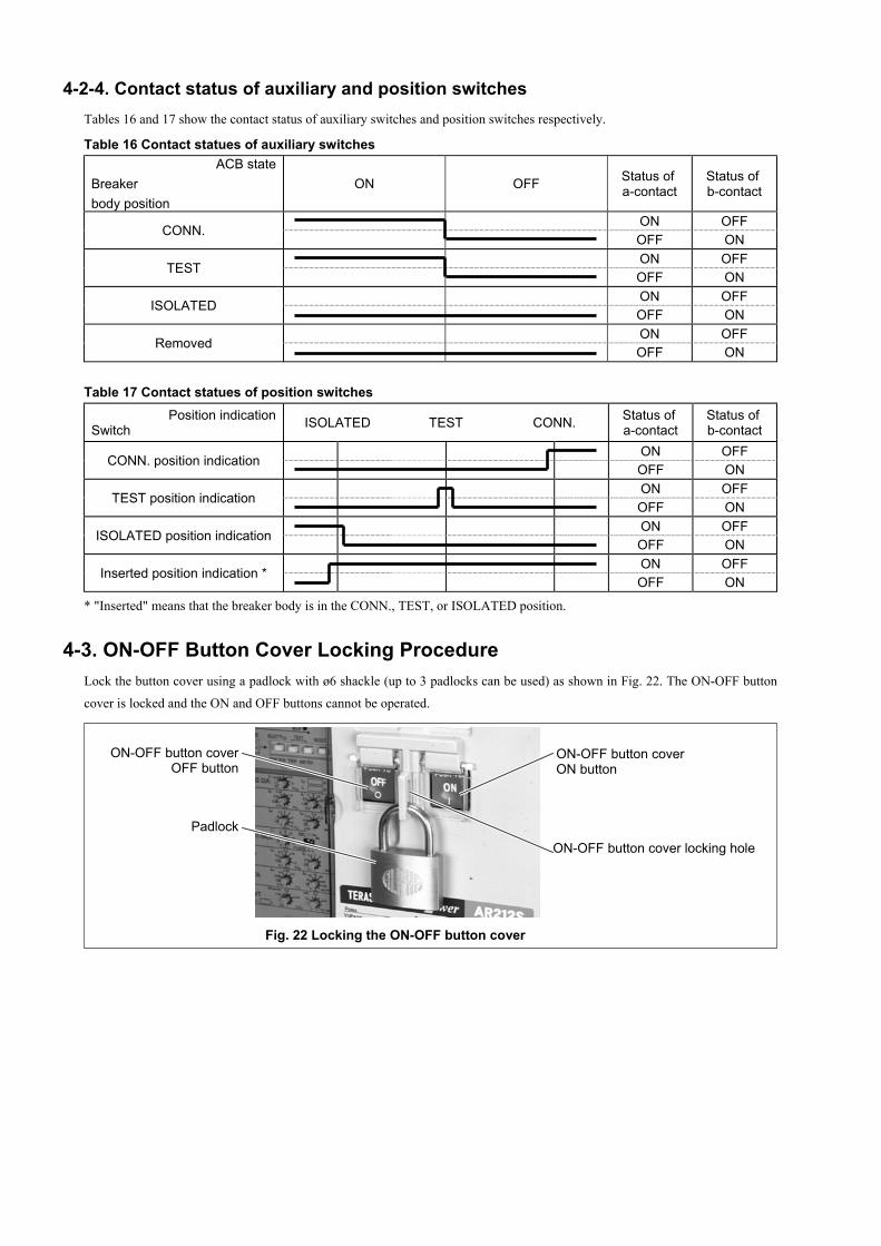
4-2-4. Contact status of auxiliary and position switchesTables 16 and 17 show the contact status of auxiliary switches and position switches respectively.
Table 16 Contact statues of auxiliary switchesACB state
Breakerbody position
ON OFF Status of a-contact
Status of b-contact
ON OFFCONN.
OFF ONON OFF
TESTOFF ONON OFF
ISOLATEDOFF ONON OFF
RemovedOFF ON
Table 17 Contact statues of position switchesPosition indication
Switch ISOLATED TEST CONN. Status of a-contact
Status of b-contact
ON OFFCONN. position indication
OFF ONON OFF
TEST position indicationOFF ONON OFF
ISOLATED position indicationOFF ONON OFF
Inserted position indication *OFF ON
* "Inserted" means that the breaker body is in the CONN., TEST, or ISOLATED position.
4-3. ON-OFF Button Cover Locking ProcedureLock the button cover using a padlock with ø6 shackle (up to 3 padlocks can be used) as shown in Fig. 22. The ON-OFF button
cover is locked and the ON and OFF buttons cannot be operated.
ON-OFF button cover locking holePadlock
ON-OFF button coverOFF button
ON-OFF button coverON button
Fig. 22 Locking the ON-OFF button cover
KRB-5237d25
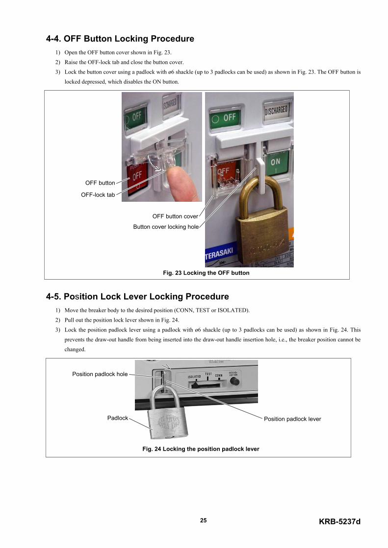
4-4. OFF Button Locking Procedure1) Open the OFF button cover shown in Fig. 23.
2) Raise the OFF-lock tab and close the button cover.
3) Lock the button cover using a padlock with ø6 shackle (up to 3 padlocks can be used) as shown in Fig. 23. The OFF button is
locked depressed, which disables the ON button.
4-5. Position Lock Lever Locking Procedure1) Move the breaker body to the desired position (CONN, TEST or ISOLATED).
2) Pull out the position lock lever shown in Fig. 24.
3) Lock the position padlock lever using a padlock with ø6 shackle (up to 3 padlocks can be used) as shown in Fig. 24. This
prevents the draw-out handle from being inserted into the draw-out handle insertion hole, i.e., the breaker position cannot be
changed.
OFF button cover
OFF button
Button cover locking hole
OFF-lock tab
Fig. 23 Locking the OFF button
Position padlock lever
Position padlock hole
Padlock
Fig. 24 Locking the position padlock lever
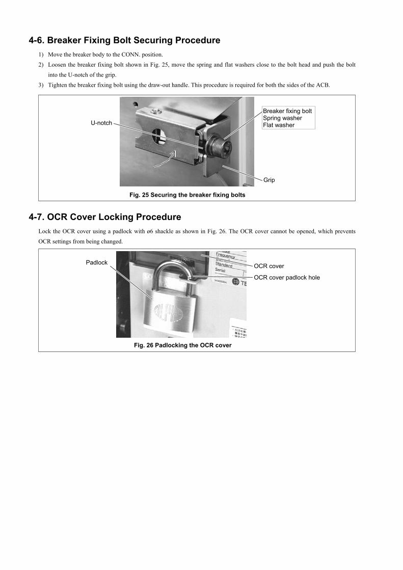
4-6. Breaker Fixing Bolt Securing Procedure1) Move the breaker body to the CONN. position.
2) Loosen the breaker fixing bolt shown in Fig. 25, move the spring and flat washers close to the bolt head and push the bolt
into the U-notch of the grip.
3) Tighten the breaker fixing bolt using the draw-out handle. This procedure is required for both the sides of the ACB.
4-7. OCR Cover Locking ProcedureLock the OCR cover using a padlock with ø6 shackle as shown in Fig. 26. The OCR cover cannot be opened, which prevents
OCR settings from being changed.
OCR coverPadlock
OCR cover padlock hole
Fig. 26 Padlocking the OCR cover
Fig. 25 Securing the breaker fixing bolts
Grip
Breaker fixing boltSpring washerFlat washerU-notch
KRB-5237d27
5. OVERCURRENT RELEASE (OCR)Options available for the type AR ACBs include a highly reliable, multi-functional overcurrent release (OCR) with a built-in 8-
bit microprocessor.
This OCR is supplied with power through a CT and main circuit current signals from current sensors. When the OCR detects a
fault, it sends a trip signal to the magnet hold trigger (MHT) or provides a trip indication or an alarm depending on the type of the
fault.
The OCR uses the root mean square sensing for the long time delay (LTD), N-phase protection (NP), and pretrip alarm (PTA)
functions. (When six times the CT rated primary current is exceeded, the peak value sensing is used instead.) If a harmonic
current flows through the ACB continuously, the root mean square sensing allows the ACB to operate normally.
The OCR is available in the three types that follows:
AGR-11L L characteristic for general feeder (for works and transformer protection)
AGR-11R R characteristic for general feeder (3 characteristics conforming to IEC60255)
AGR-11S S characteristic for generator protection
5-1. SpecificationsSpecifications of the OCR are shown in Table 18 and Fig. 27.
Table 18 Specifications of type AGR-11 OCR ( : Standard, : Optional, –: Not applicable)
Application For general feeder For generatorprotection
Characteristic L R SType designation AGR-11L-XX AGR-11R-XXX AGR-11S-XXSuffix (XX or XXX) of type designation *1 AL GL PS PG AL_ GL_ PS_ PG_ AL PS
Referencesection
Long time delay trip (LT)Short time delay trip (ST)Instantaneous trip (INST/MCR)Ground fault trip (GF) *2 – – – – – –N-phase protection *3 – –
Protectivefunction
Pretrip alarm (PTA) *3 – – – – –
5-3.
COLD/HOT (LT) *4 – – – – – – 5-1.I2t ON/OFF (ST) 5-3.INST/MCR (INST) *5 5-1.
Protectioncharacteristic
I2t ON/OFF (GF) – – – – – – 5-3.Group indication LED andcontact output – – – – –
Individual indication LEDs andcontact output – – – – –
“Tripped” indication
Tripindication
“Spring charged” indication
5-4.
Test function – – – – – 5-5.
Control power supply Notrequired
Notrequired Required Required Not
requiredNot
required Required Required Notrequired Required 3-3.
*1: An under bar in the type designatios means a number from 1 to 5 representing a type of the long time delay trip (LT) characteristic as follows:"1”: I0.02t, “2”: It, “3”: I2t, “4”: I3t, “5”: I4t.The type of LT characteristics is factory set according to your order specification. Refer to section 5-3-2.
*2: The OCR is factory equipped with the ground fault indication function only or with both the ground fault trip function and ground fault indication function accordingto your order specification. Control power supply is required when the CT rated primary current [ICT] is not more than 800A and the ground fault trip pickup currentsetting [IG] is 10% of ICT.
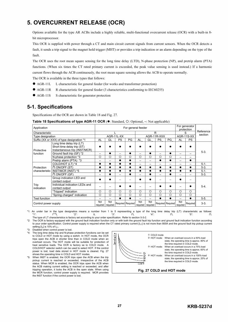
*3: Disabled when control power is lost. *4: The long time delay trip and N-phase protection functions can be set
to COLD or HOT mode by using a switch. In HOT mode, the OCRtrips open the ACB in shorter time than in COLD mode when anoverload occurs. The HOT mode will be suitable for protection ofheat sensitive loads. The OCR is factory se to COLD mode. ACOLD/HOT selector switch can be used to select HOT. If the controlpower is lost, load data stored in HOT mode is cleared. Fig. 27shows the operating time in COLD and HOT modes.
*5: When INST is enabled, the OCR trips open the ACB when the trippickup current is reached or exceeded, irrespective of the ACBstatus. When MCR is enabled, the OCR trips open the ACB whenthe ACB making current setting is reached or exceeded, and aftertripping operation, it locks the ACB in the open state. When usingthe MCR function, control power supply is required. MCR providesthe INST function if the control power is lost.
1 COLD mode2 HOT mode: When an overload occurs in a 50%-load
state, the operating time is approx. 80% ofthe time required in COLD mode.
3 HOT mode: When an overload occurs in a 75%-loadstate, the operating time is approx. 60% ofthe time required in COLD mode.
4 HOT mode: When an overload occurs in a 100%-loadstate, the operating time is approx. 20% ofthe time required in COLD mode.
Fig. 27 COLD and HOT mode
5-2. OCR Setting Procedure
CAUTION OCR setting changes must be performed by competent persons. Use a small flatblade screwdriver with a torque of not more than 0.1 N·m or a force of not more than 0.1 N when adjustingthe setting switches (rotary step switches or slide switches). An excessive torque or force may cause a malfunction.
The following describes how to set the OCR.
1) Open the ACB.
2) If the OCR is fed by the control power supply, isolate the OCR from the power supply by e.g., moving the breaker body to
the ISOLATED position.
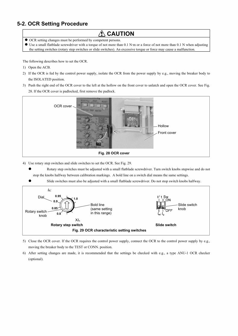
3) Push the right end of the OCR cover to the left at the hollow on the front cover to unlatch and open the OCR cover. See Fig.
28. If the OCR cover is padlocked, first remove the padlock.
4) Use rotary step switches and slide switches to set the OCR. See Fig. 29.
Rotary step switches must be adjusted with a small flatblade screwdriver. Turn switch knobs stepwise and do not
stop the knobs halfway between calibration markings. A bold line on a switch dial means the same settings.
Slide switches must also be adjusted with a small flatblade screwdriver. Do not stop switch knobs halfway.
5) Close the OCR cover. If the OCR requires the control power supply, connect the OCR to the control power supply by e.g.,
moving the breaker body to the TEST or CONN. position.
6) After setting changes are made, it is recommended that the settings be checked with e.g., a type ANU-1 OCR checker
(optional).
Dial
Rotary switchknob
Bold line(same settingin this range)
IR:0.95
0.9
0.85
0.8
XIn
1.0
Slide switchknob
Rotary step switch Slide switchFig. 29 OCR characteristic setting switches
OCR cover
Hollow
Front cover
Fig. 28 OCR cover
KRB-5237d29
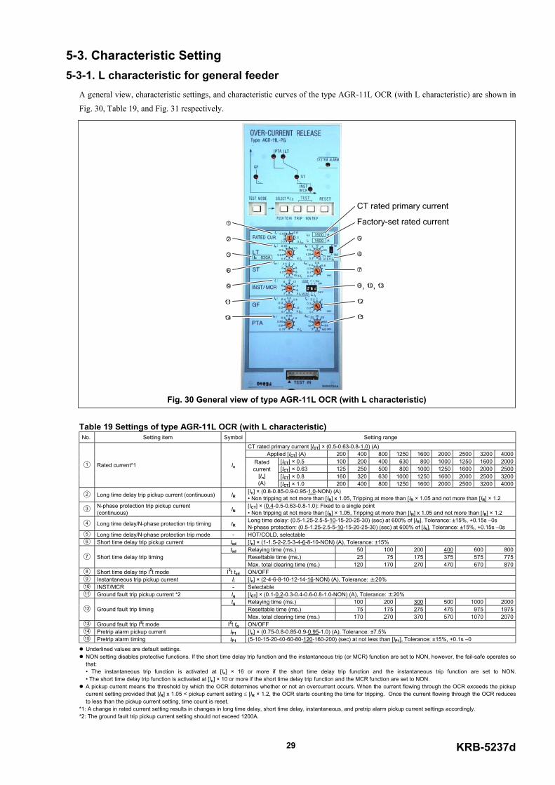
5-3. Characteristic Setting5-3-1. L characteristic for general feeder
A general view, characteristic settings, and characteristic curves of the type AGR-11L OCR (with L characteristic) are shown in
Fig. 30, Table 19, and Fig. 31 respectively.
Table 19 Settings of type AGR-11L OCR (with L characteristic) No. Setting item Symbol Setting range
CT rated primary current [ICT] × (0.5-0.63-0.8-1.0) (A)Applied [ICT] (A) 200 400 800 1250 1600 2000 2500 3200 4000
[ICT] × 0.5 100 200 400 630 800 1000 1250 1600 2000[ICT] × 0.63 125 250 500 800 1000 1250 1600 2000 2500[ICT] × 0.8 160 320 630 1000 1250 1600 2000 2500 3200
1 Rated current*1 InRatedcurrent
[In](A) [ICT] × 1.0 200 400 800 1250 1600 2000 2500 3200 4000
2 Long time delay trip pickup current (continuous) IR[In] × (0.8-0.85-0.9-0.95-1.0-NON) (A)• Non tripping at not more than [IR] x 1.05, Tripping at more than [IR × 1.05 and not more than [IR] × 1.2
3 N-phase protection trip pickup current(continuous) IN
[ICT] × (0.4-0.5-0.63-0.8-1.0): Fixed to a single point• Non tripping at not more than [IN] × 1.05, Tripping at more than [IN] x 1.05 and not more than [IR] × 1.2
4 Long time delay/N-phase protection trip timing tRLong time delay: (0.5-1.25-2.5-5-10-15-20-25-30) (sec) at 600% of [IR], Tolerance: ±15%, +0.15s –0sN-phase protection: (0.5-1.25-2.5-5-10-15-20-25-30) (sec) at 600% of [IN], Tolerance: ±15%, +0.15s –0s
5 Long time delay/N-phase protection trip mode - HOT/COLD, selectable6 Short time delay trip pickup current Isd [In] × (1-1.5-2-2.5-3-4-6-8-10-NON) (A), Tolerance: ±15%
tsd Relaying time (ms.) 50 100 200 400 600 800Resettable time (ms.) 25 75 175 375 575 7757 Short time delay trip timingMax. total clearing time (ms.) 120 170 270 470 670 870
8 Short time delay trip I2t mode I2t tsd ON/OFF9 Instantaneous trip pickup current Ii [In] × (2-4-6-8-10-12-14-16-NON) (A), Tolerance: ±20%10 INST/MCR - Selectable11 Ground fault trip pickup current *2 Ig [ICT] × (0.1-0.2-0.3-0.4-0.6-0.8-1.0-NON) (A), Tolerance: ±20%
tg Relaying time (ms.) 100 200 300 500 1000 2000Resettable time (ms.) 75 175 275 475 975 197512 Ground fault trip timingMax. total clearing time (ms.) 170 270 370 570 1070 2070
13 Ground fault trip I2t mode I2t tg ON/OFF14 Pretrip alarm pickup current IP1 [In] × (0.75-0.8-0.85-0.9-0.95-1.0) (A), Tolerance: ±7.5%15 Pretrip alarm timing tP1 (5-10-15-20-40-60-80-120-160-200) (sec) at not less than [IP1], Tolerance: ±15%, +0.1s –0
Underlined values are default settings. NON setting disables protective functions. If the short time delay trip function and the instantaneous trip (or MCR) function are set to NON, however, the fail-safe operates sothat:• The instantaneous trip function is activated at [In] × 16 or more if the short time delay trip function and the instantaneous trip function are set to NON.• The short time delay trip function is activated at [In] × 10 or more if the short time delay trip function and the MCR function are set to NON.
A pickup current means the threshold by which the OCR determines whether or not an overcurrent occurs. When the current flowing through the OCR exceeds the pickupcurrent setting provided that [IR] x 1.05 < pickup current setting ≤ [IR × 1.2, the OCR starts counting the time for tripping. Once the current flowing through the OCR reducesto less than the pickup current setting, time count is reset.
*1: A change in rated current setting results in changes in long time delay, short time delay, instantaneous, and pretrip alarm pickup current settings accordingly. *2: The ground fault trip pickup current setting should not exceed 1200A.
1
2
3 45
6 7
8 , 10, 139
11 12
14 15
Factory-set rated current
CT rated primary current
Fig. 30 General view of type AGR-11L OCR (with L characteristic)
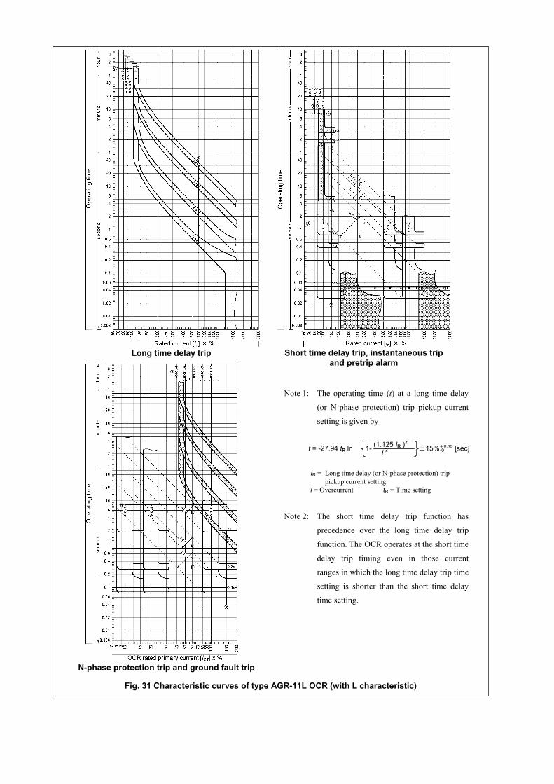
Note 1: The operating time (t) at a long time delay
(or N-phase protection) trip pickup current
setting is given by
IR = Long time delay (or N-phase protection) trippickup current setting
i = Overcurrent tR = Time setting
Note 2: The short time delay trip function has
precedence over the long time delay trip
function. The OCR operates at the short time
delay trip timing even in those current
ranges in which the long time delay trip time
setting is shorter than the short time delay
time setting.
Long time delay trip Short time delay trip, instantaneous tripand pretrip alarm
N-phase protection trip and ground fault trip
t = -27.94 tR ln (1.125 IR )2
i 2 ±15%+0.15 [sec]1- -0
Fig. 31 Characteristic curves of type AGR-11L OCR (with L characteristic)
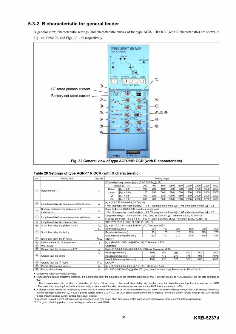
KRB-5237d31
5-3-2. R characteristic for general feederA general view, characteristic settings, and characteristic curves of the type AGR-11R OCR (with R characteristic) are shown in
Fig. 32, Table 20, and Figs. 33 - 35 respectively.
Table 20 Settings of type AGR-11R OCR (with R characteristic) No. Setting item Symbol Setting range
CT rated primary current [ICT] × (0.5-0.63-0.8-1.0) (A)Applied [ICT] (A) 200 400 800 1250 1600 2000 2500 3200 4000
[ICT] × 0.5 100 200 400 630 800 1000 1250 1600 2000[ICT] × 0.63 125 250 500 800 1000 1250 1600 2000 2500[ICT] × 0.8 160 320 630 1000 1250 1600 2000 2500 3200
1 Rated curent *1 InRatedcurrent
[In](A) [ICT] × 1.0 200 400 800 1250 1600 2000 2500 3200 4000
2 Long time delay trip pickup current (continuous) IR[In] x (0.8-0.85-0.9-0.95-1.0-NON) (A)• Non tripping at not more than [IR] × 1.05, Tripping at more than [IR] × 1.05 and not more than [IR] × 1.2
3N-phase protection trip pickup current(continuous) IN
[ICT] x (0.4-0.5-0.63-0.8-1.0): Fixed to a single point• Non tripping at not more than [IN] × 1.05, Tripping at more than [IN] × 1.05 and not more than [IR] × 1.2
4 Long time delay/N-phase protection trip timing tRLong time delay: (1-2-3-4-5-6-7-8-10-13) (sec) at 300% of [IR], Tolerance: ±20%, +0.15s –0sN-phase protection: (1-2-3-4-5-6-7-8-10-13) (sec) ) at 300% of [IN], Tolerance: ±20%, +0.15s –0s
5 Long time delay trip characteristic - “R1”: I0.02t, “R2”: It, “R3”: I2t, “R4”: I3t, “R5”: I4t6 Short time delay trip pickup current Isd [In] × (1-1.5-2-2.5-3-4-6-8-10-NON) (A), Tolerance: ±15%
tsd Relaying time (ms.) 50 100 200 400 600 800Resettable time (ms.) 25 75 175 375 575 7757 Short time delay trip timingMax. total clearing time (ms.) 120 170 270 470 670 870
8 Short time delay trip I2t mode I2t tsd ON/OFF9 Instantaneous trip pickup current Ii [In] × (2-4-6-8-10-12-14-16-NON) (A), Tolerance: ±20%10 INST/MCR - Selectable11 Ground fault trip pickup current *2 Ig [ICT] × (0.1-0.2-0.3-0.4-0.6-0.8-1.0-NON) (A), Tolerance: ±20%
tg Relaying time (ms.) 100 200 300 500 1000 2000Resettable time (ms.) 75 175 275 475 975 197512 Ground fault trip timingMax. total clearing time (ms.) 170 270 370 570 1070 2070
13 Ground fault trip I2t mode I2t tg ON/OFF14 Pretrip alarm pickup current IP1 [In] x (0.75-0.8-0.85-0.9-0.95-1.0) (A), Tolerance: ±7.5%15 Pretrip alarm timing tP1 (5-10-15-20-40-60-80-120-160-200) (sec) at not less than [IP1], Tolerance: ±15%, +0.1s –0
Underlined values are default settings. NON setting disables protective functions. If the short time delay trip function and the instantaneous trip (or MCR) function are set to NON, however, the fail-safe operates sothat:• The instantaneous trip function is activated at [In] × 16 or more if the short time delay trip function and the instantaneous trip function are set to NON.• The short time delay trip function is activated at [In] × 10 or more if the short time delay trip function and the MCR function are set to NON.
A pickup current means the threshold by which the OCR determines whether or not an overcurrent occurs. When the current flowing through the OCR exceeds the pickupcurrent setting provided that [IR] x 1.05 < pickup current setting ≤ [IR × 1.2, the OCR starts counting the time for tripping. Once the current flowing through the OCR reducesto less than the pickup current setting, time count is reset.
*1: A change in rated current setting results in changes in long time delay, short time delay, instantaneous, and pretrip alarm pickup current settings accordingly. *2: The ground fault trip pickup current setting should not exceed 1200A.
Fig. 32 General view of type AGR-11R OCR (with R characteristic)
Factory-set rated current
CT rated primary current①
②
③
④
⑥
⑦
⑧,⑩,⑬
⑨
⑪
⑫
⑭
⑮
⑤
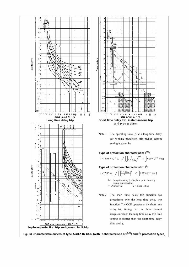
Fig. 33 Characteristic curves of type AGR-11R OCR (with R characteristic of I0.02t and I3t protection types)
Note 1: The operating time (t) at a long time delay
(or N-phase protection) trip pickup current
setting is given by
Type of protection characteristic: I0.02t
Type of protection characteristic: I3t
IR = Long time delay (or N-phase protection) trippickup current setting
i = Overcurrent tR = Time setting
Note 2: The short time delay trip function has
precedence over the long time delay trip
function. The OCR operates at the short time
delay trip timing even in those current
ranges in which the long time delay trip time
setting is shorter than the short time delay
time setting.
±20%+0.15 [sec]t ≒1.981×10⁻²・tR 1.125IRi -1
0.02-0
Long time delay trip Short time delay trip, instantaneous tripand pretrip alarm
N-phase protection trip and ground fault trip
t ≒17.96・tR1.125IRi -1
3±20%+0.15 [sec]-0
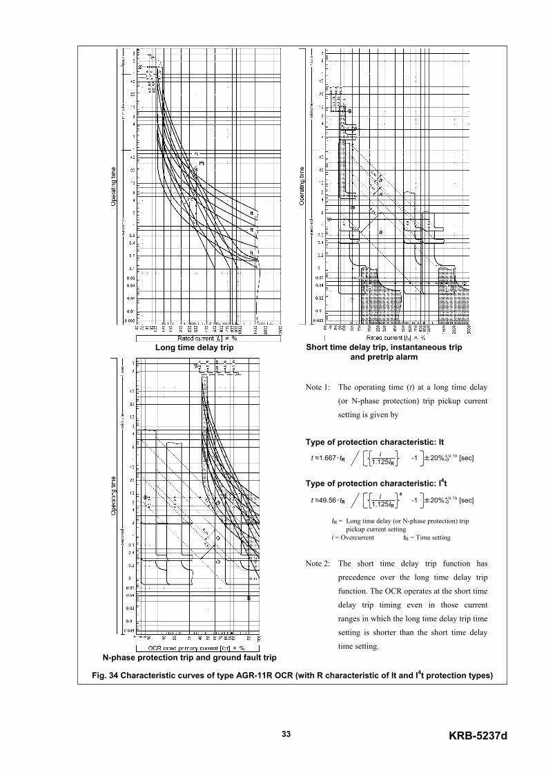
KRB-5237d33
Note 1: The operating time (t) at a long time delay
(or N-phase protection) trip pickup current
setting is given by
Type of protection characteristic: It
Type of protection characteristic: I4t
IR = Long time delay (or N-phase protection) trippickup current setting
i = Overcurrent tR = Time setting
Note 2: The short time delay trip function has
precedence over the long time delay trip
function. The OCR operates at the short time
delay trip timing even in those current
ranges in which the long time delay trip time
setting is shorter than the short time delay
time setting.
t ≒1.667・tR 1.125IRi -1 ±20%+0.15 [sec]-0
t ≒49.56・tR 1.125IRi -1
4±20%+0.15 [sec]-0
Fig. 34 Characteristic curves of type AGR-11R OCR (with R characteristic of It and I4t protection types)
Long time delay trip Short time delay trip, instantaneous tripand pretrip alarm
N-phase protection trip and ground fault trip
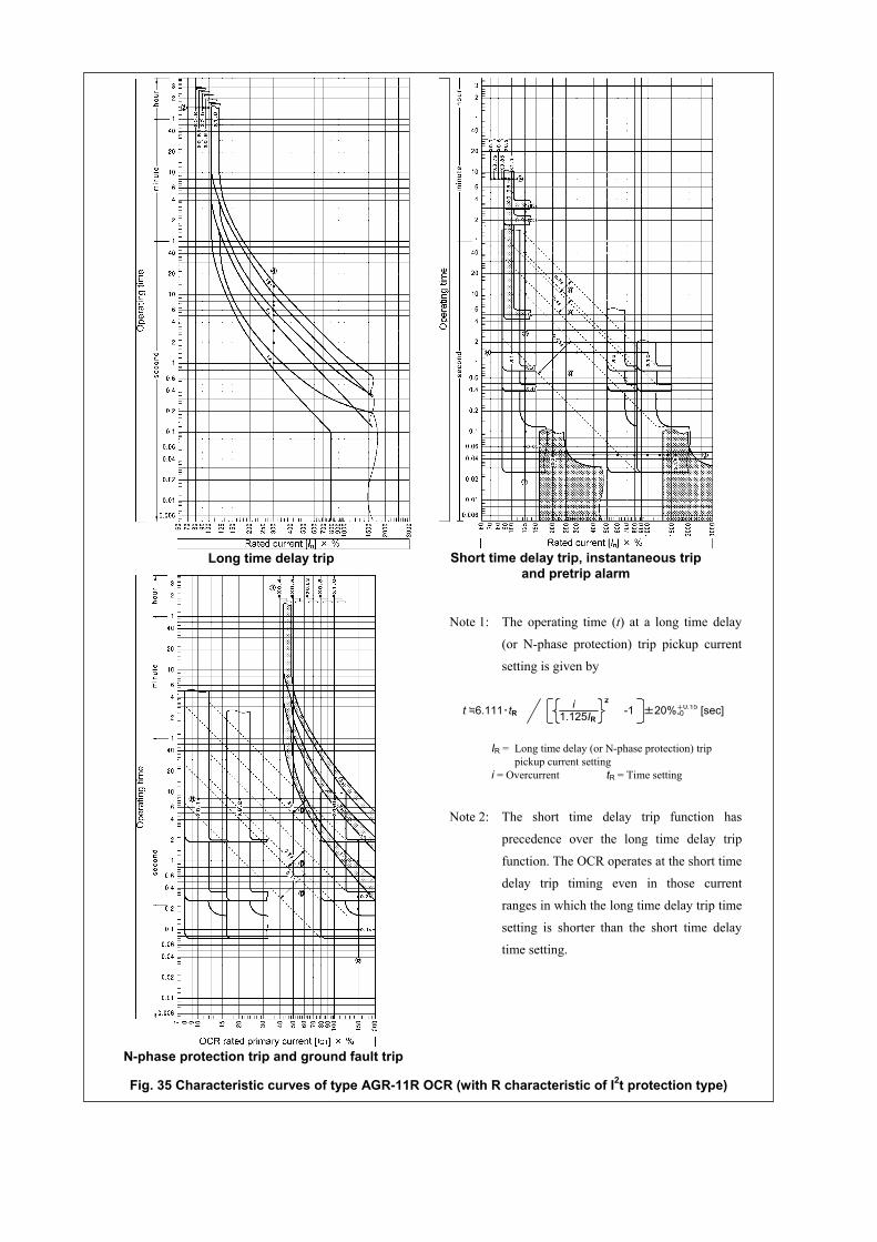
Note 1: The operating time (t) at a long time delay
(or N-phase protection) trip pickup current
setting is given by
IR = Long time delay (or N-phase protection) trippickup current setting
i = Overcurrent tR = Time setting
Note 2: The short time delay trip function has
precedence over the long time delay trip
function. The OCR operates at the short time
delay trip timing even in those current
ranges in which the long time delay trip time
setting is shorter than the short time delay
time setting.
Long time delay trip Short time delay trip, instantaneous tripand pretrip alarm
N-phase protection trip and ground fault trip
Fig. 35 Characteristic curves of type AGR-11R OCR (with R characteristic of I2t protection type)
t ≒6.111・tR 1.125IRi -1
2±20%+0.15 [sec]-0
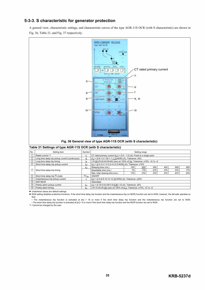
KRB-5237d35
5-3-3. S characteristic for generator protectionA general view, characteristic settings, and characteristic curves of the type AGR-11S OCR (with S characteristic) are shown in
Fig. 36, Table 21, and Fig. 37 respectively.
Table 21 Settings of type AGR-11S OCR (with S characteristic) No. Setting item Symbol Setting range1 Rated current *1 In CT rated primary current [ICT] × (0.5 - 1.0) (A): Fixed to a single point2 Long time delay trip pickup current (continuous) IR [In] × (0.8-1.0-1.05-1.1-1.15-NON) (A), Tolerance: ±5%4 Long time delay trip timing tR (15-20-25-30-40-50-60) (sec) at 120% of [IR], Tolerance: ±15%, +0.1s –06 Short time delay trip pickup current Isd [In] × (2-2.5-2.7-3-3.5-4-4.5-5-NON) (A), Tolerance: ±10%
tsd Relaying time (ms.) 100 200 300 400 600 800Resettable time (ms.) 75 175 275 375 575 7757 Short time delay trip timingMax. total clearing time (ms.) 170 270 370 470 670 870
8 Short time delay trip I2t mode I2t tsd ON/OFF9 Instantaneous trip pickup current Ii [In] × (2-4-6-8-10-12-14-16-NON) (A), Tolerance: ±20%10 INST/MCR - Selectable14 Pretrip alarm pickup current IP1 [In] × (0.75-0.8-0.85-0.9-0.95-1.0) (A), Tolerance: ±5%15 Pretrip alarm timing tP1 (10-15-20-25-30) (sec) at 120% of [IP1], Tolerance: ±15%, +0.1s –0
Underlined values are default settings. NON setting disables protective functions. If the short time delay trip function and the instantaneous trip (or MCR) function are set to NON, however, the fail-safe operates sothat:• The instantaneous trip function is activated at [In] × 16 or more if the short time delay trip function and the instantaneous trip function are set to NON.• The short time delay trip function is activated at [In] × 5 or more if the short time delay trip function and the MCR function are set to NON.
*1: Cannot be changed by the user.
2
4
6 7
8 , 109
14 15
1
CT rated primary current
Fig. 36 General view of type AGR-11S OCR (with S characteristic)
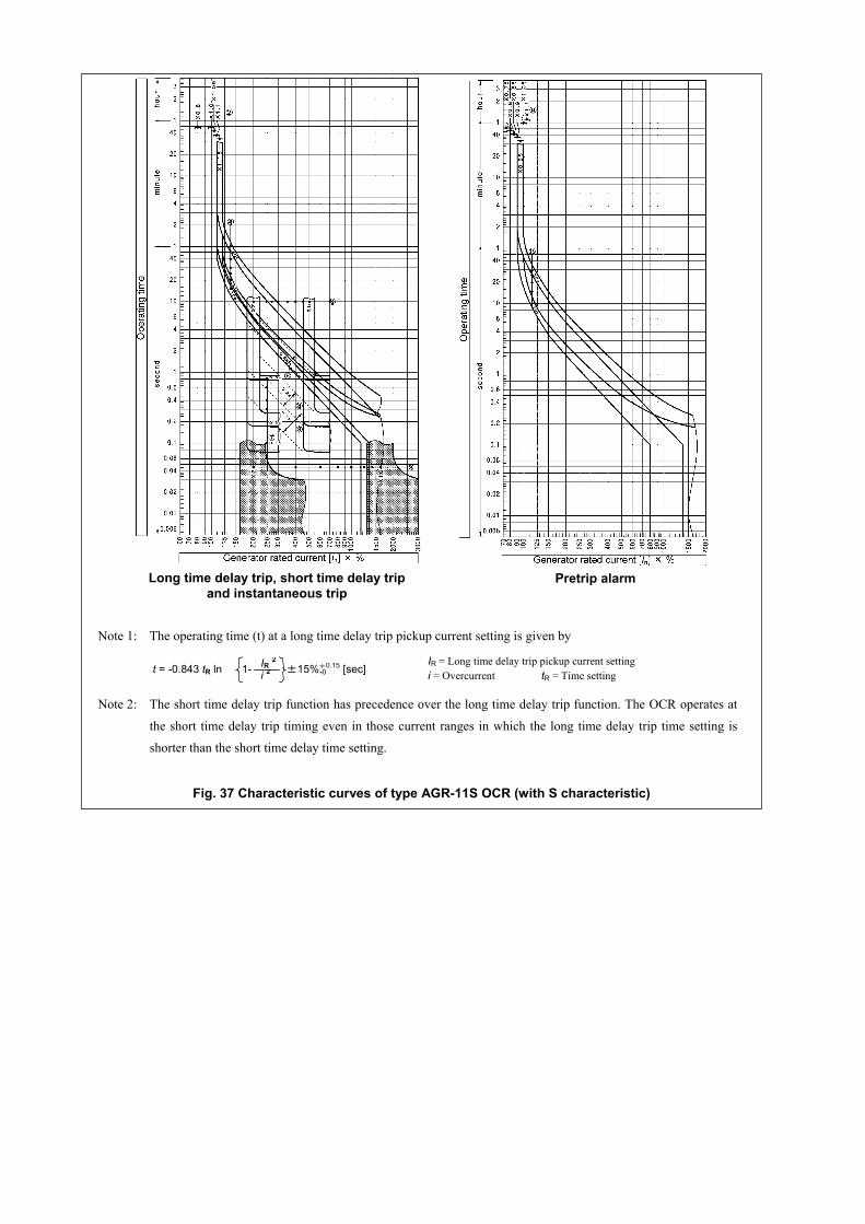
Long time delay trip, short time delay tripand instantaneous trip
Pretrip alarm
Fig. 37 Characteristic curves of type AGR-11S OCR (with S characteristic)
Note 1: The operating time (t) at a long time delay trip pickup current setting is given by
IR = Long time delay trip pickup current settingi = Overcurrent tR = Time setting
Note 2: The short time delay trip function has precedence over the long time delay trip function. The OCR operates at
the short time delay trip timing even in those current ranges in which the long time delay trip time setting is
shorter than the short time delay time setting.
t = -0.843 tR ln IR 2i 21- ±15%+0.15 [sec]-0
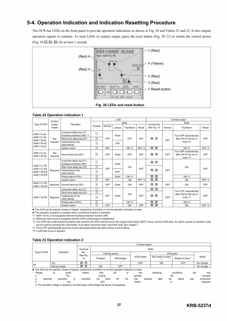
KRB-5237d37
5-4. Operation Indication and Indication Resetting ProcedureThe OCR has LEDs on the front panel to provide operation indications as shown in Fig. 38 and Tables 22 and 23. It also outputs
operation signals to contacts. To reset LEDs or contact output, press the reset button (Fig. 38 7 ) or isolate the control power
(Fig. 10 11 ,12 , 21 ) for at least 1 second.
Table 22 Operation indication 1LED Contact output
State StateType of OCRControlpowersupply
OperationPosition Normal pickup Trip/Alarm Reset
Terminal No.See Fig. 10 Normal Trip/Alarm Reset
Long time delay trip (LT)N-phase protection (NP) *1 1
Short time delay trip (ST) 2Flash
Instantaneous trip(INST/MCR) 3
OFF
OFF
OFF OFF 05 , 15Turn OFF automaticallyafter ON for 40 ms or
more *5OFF
AGR-11L-ALAGR-11L-GLAGR-11R-ALAGR-11R-GLAGR-11S-AL
Notrequired
System alarm 4 OFF - ON *2 OFF *3 05 , 26
OFF
ON *2 OFF *3
AGR-11L-GLAGR-11R-GL
Notrequired Ground fault trip (GF) 5 OFF Flash OFF OFF 05 , 15 OFF
Turn OFF automaticallyafter ON for 40 ms or
more *5OFF
Long time delay trip (LT)N-phase protection (NP) 1 05 , 15
Short time delay trip (ST) 2Flash
Instantaneous trip(INST/MCR) 3 OFF
ON05 , 25
ON
Pretrip alarm (PTA) 6
OFF
Flash ON *4
OFF
05 , 06 ON *4
OFFAGR-11L-PSAGR-11L-PGAGR-11R-PSAGR-11R-PG
Required
System alarm 4 OFF - ON OFF *3 05 , 26
OFF
ON OFF *3AGR-11L-PGAGR-11R-PG Required Ground fault trip (GF) 5 OFF Flash ON OFF 05 , 16 OFF ON OFF
Long time delay trip (LT) 1 05 , 15
Short time delay trip (ST) 2
Instantaneous trip(INST/MCR) 3
ON05 , 25
Turn OFF automaticallyafter ON for 500 ms or
more *5
Pretrip alarm (PTA) 6
OFF Flash
ON *4
OFF
05 , 06 ON *4
OFFAGR-11S-PS Required
System alarm 4 OFF - ON OFF 05 , 26
OFF
ON OFF *3
The ACB can be opened, closed or tripped, irrespective of whether or not the operation indication is reset. The operation indication is updated when a protective function is activated.
*1: AGR-11S-AL is not equipped with the N-phase protection function (NP). *2: When the main circuit is energized and the OCR control power is established. *3: The OCR has a self-monitoring feature that monitors the OCR internal circuit, the magnet hold tripper (MHT) circuit, and the ACB state. An alarm caused by transient noise
can be reset by pressing the reset button. If an alarm cannot be reset, check the ACB. See chapter 7. *4: Turns OFF automatically when the current decreases below the alarm pickup current setting. *5: A self-hold circuit is required.
Table 23 Operation indication 2Contact output
State
Closing spring ACB openType of OCR OperationTerminal
No.See Fig.
10 Charged DischargedACB closed Not ready to close
* Ready to close *Reset
Trip 05 , 17 - - OFF ON OFF No changeAll
Spring charge 05 , 27 ON OFF - - - No change The ACB can be opened, closed or tripped, irrespective of whether or not the operation indication is reset.
* “Ready to close” means that all of the following conditions are met:1. The closing springs are charged.2. Opening operation is complete (At least 40 ms has elapsed after trip signal was produced).3. The OFF button is released.4. The specified voltage is applied to the fixed type undervoltage trip device (if equipped).
1 (Red)
3 (Red)
4 (Yellow)
(Red) 5
(Red) 6
7 Reset button
2 (Red)
Fig. 38 LEDs and reset button
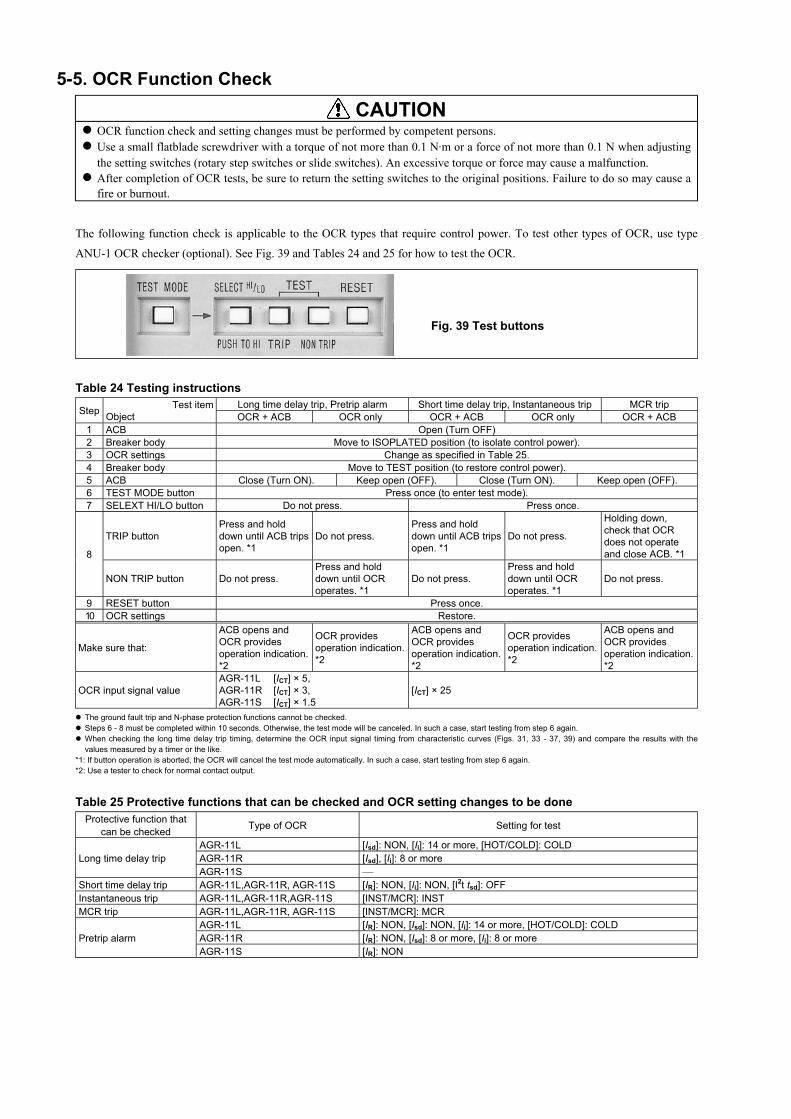
5-5. OCR Function Check CAUTION
OCR function check and setting changes must be performed by competent persons. Use a small flatblade screwdriver with a torque of not more than 0.1 N·m or a force of not more than 0.1 N when adjustingthe setting switches (rotary step switches or slide switches). An excessive torque or force may cause a malfunction.
After completion of OCR tests, be sure to return the setting switches to the original positions. Failure to do so may cause afire or burnout.
The following function check is applicable to the OCR types that require control power. To test other types of OCR, use type
ANU-1 OCR checker (optional). See Fig. 39 and Tables 24 and 25 for how to test the OCR.
Table 24 Testing instructionsLong time delay trip, Pretrip alarm Short time delay trip, Instantaneous trip MCR tripStep Test item
Object OCR + ACB OCR only OCR + ACB OCR only OCR + ACB1 ACB Open (Turn OFF)2 Breaker body Move to ISOPLATED position (to isolate control power).3 OCR settings Change as specified in Table 25.4 Breaker body Move to TEST position (to restore control power).5 ACB Close (Turn ON). Keep open (OFF). Close (Turn ON). Keep open (OFF).6 TEST MODE button Press once (to enter test mode).7 SELEXT HI/LO button Do not press. Press once.
TRIP buttonPress and holddown until ACB tripsopen. *1
Do not press.Press and holddown until ACB tripsopen. *1
Do not press.
Holding down,check that OCRdoes not operateand close ACB. *18
NON TRIP button Do not press.Press and holddown until OCRoperates. *1
Do not press.Press and holddown until OCRoperates. *1
Do not press.
9 RESET button Press once.10 OCR settings Restore.
Make sure that:
ACB opens andOCR providesoperation indication.*2
OCR providesoperation indication.*2
ACB opens andOCR providesoperation indication.*2
OCR providesoperation indication.*2
ACB opens andOCR providesoperation indication.*2
OCR input signal valueAGR-11L [ICT] × 5,AGR-11R [ICT] × 3,AGR-11S [ICT] × 1.5
[ICT] × 25
The ground fault trip and N-phase protection functions cannot be checked. Steps 6 - 8 must be completed within 10 seconds. Otherwise, the test mode will be canceled. In such a case, start testing from step 6 again. When checking the long time delay trip timing, determine the OCR input signal timing from characteristic curves (Figs. 31, 33 - 37, 39) and compare the results with thevalues measured by a timer or the like.
*1: If button operation is aborted, the OCR will cancel the test mode automatically. In such a case, start testing from step 6 again. *2: Use a tester to check for normal contact output.
Table 25 Protective functions that can be checked and OCR setting changes to be doneProtective function that
can be checked Type of OCR Setting for test
AGR-11L [Isd]: NON, [Ii]: 14 or more, [HOT/COLD]: COLDAGR-11R [Isd], [Ii]: 8 or moreLong time delay tripAGR-11S
Short time delay trip AGR-11L,AGR-11R, AGR-11S [IR]: NON, [Ii]: NON, [I2t tsd]: OFFInstantaneous trip AGR-11L,AGR-11R,AGR-11S [INST/MCR]: INSTMCR trip AGR-11L,AGR-11R, AGR-11S [INST/MCR]: MCR
AGR-11L [IR]: NON, [Isd]: NON, [Ii]: 14 or more, [HOT/COLD]: COLDAGR-11R [IR]: NON, [Isd]: 8 or more, [Ii]: 8 or morePretrip alarmAGR-11S [IR]: NON
Fig. 39 Test buttons

KRB-5237d39
6. MAINTENANCE, INSPECTION AND PARTS REPLACEMENTThis chapter describes the maintenance and inspection procedure for the AR series ACBs.
The service life of the ACB depends on the working and environmental conditions. The ACB is exposed to mechanical and
electrical stresses and thus suffers gradual degradation during use, which will increase the possibility of malfunctions. Preventive
maintenance and periodical inspection are very important to avoid any functional degradation, prevent malfunctions, extend the
service life, and ensure safe operation.
The appropriate frequency of maintenance and inspection of the ACB varies depending on the installation conditions, the number
of tripping operations, the magnitude of breaking current, and other factors that are to be considered empirically. As a guideline,
Table 26 shows the recommended inspection frequency. See section 6-1 for detailed maintenance and inspection procedures.
Table 26 Frequency of maintenance and inspectionFrequency in interval or number of open/close cyclesCategory Working and environmental
conditionsInspection
level Interval Number of open/close cyclesOpen/closecondition
800AF orless
1250AF - 2500AF 3200AF or more
Nearly no currentlevel Every 1000 cyclesNormal/
Detailed
• Every year or 2 years• Every year after 3 years
since installation• Every half year after 6
years since installationRated currentlevel
Every 1000cycles
Every 500cycles Every 100 cycles
Thorough
• Every 5 or 6 years• Every 4 years after 6 years
since installation• Every year or 2 years after
10 years since installation
Every 4000 cycles
Normal
• Not so dusty, • Not so much corrosive
gases, • Ambient temperature:
35°C or lower • Not so humid, • Number of open/close
cycles per day: 2 or lessEx.Switchboards in electric
installation rooms,Control rooms,Building installation Overhaul When abnormality is found during normal or through inspection
Open/closecondition
800AF orless
1250AF - 2500AF 3200AF or more
Nearly no currentlevel
• Every 1000 cycles• Every 500 cycles after 1000 cyclesNormal/
Detailed
• Every year• Every half year after 2
years since installation Rated currentlevel
• Every 1000cycles
• Every 500cycles after1000 cycles
• Every 500cycles
• Every 250cycles after500 cycles
• Every 100cycles
• Every 50 cyclesafter 100 cycles
Thorough
• Every 2 or 3 years• Every 2 years after 6 years
since installation• Every year after 10 years
since installation
• Every 2500 - 3000 cycles• Every 2000 cycles after 3000 cycles
Harsh
• Highly dusty, • Much corrosive gases, • Ambient temperature:
45°C or higher, • Highly humid, • Number of open/close
cycles per day: 4 or more, • Always exposed to
vibrationsEx. Iron or chemical plants
Engine rooms (withoutventilation),Cogenerationinstallation,Ferryboats
Overhaul When abnormality is found during normal or through inspection
Open/closecondition
800AF orless
1250AF - 2500AF 3200AF or more
Overcurrent level(approx. 6 timesthe rated current)
Every 25cycles
Every 25cycles Every 25 cyclesThorough When abnormality occurs
Level exceedingovercurrent level Every time Every time Every time
Abnormal
• Open/close operation dueto overload,
• Tripping due toshortcircuit,
• Accidentally submergedOverhaul When ACB is deemed to be repairable at through inspection
Normal inspection includes inspection and actions that can be done only with removing the arc chamber, contacts, front cover andthe like. Normal inspection can be performed by the user. Terasaki also provides normal inspection service.
Detailed inspection includes inspection, actions, and parts replacement that will be done to prevent functional degradation causedby aging or the like when abnormality is found during normal inspection.You are recommended to use Terasaki’s detailed inspection service.
Thorough inspection must be left to Terasaki. Overhaul will be done in a Terasaki’s factory.
About the service lifeThe expected service life of AR series ACBs is shown in the "Endurance in number of ON-OFF cycles" rows in Tables 3 and
4. "With maintenance" in the tables means that appropriate inspection, maintenance, repair, and parts replacement are
performed according to the instructions in this chapter. But, when an ACB performs three times of tripping operation nearly at
the rated breaking current (three standard operating duty cycles), it is at the end of its safe service life even if thorough
inspection is done every time it trips open. Such an ACB will be apt to suffer malfunctions and should be replaced without
delay to avoid frequent inspection and parts replacement.
See section 6-2 for detailed parts replacement procedures.
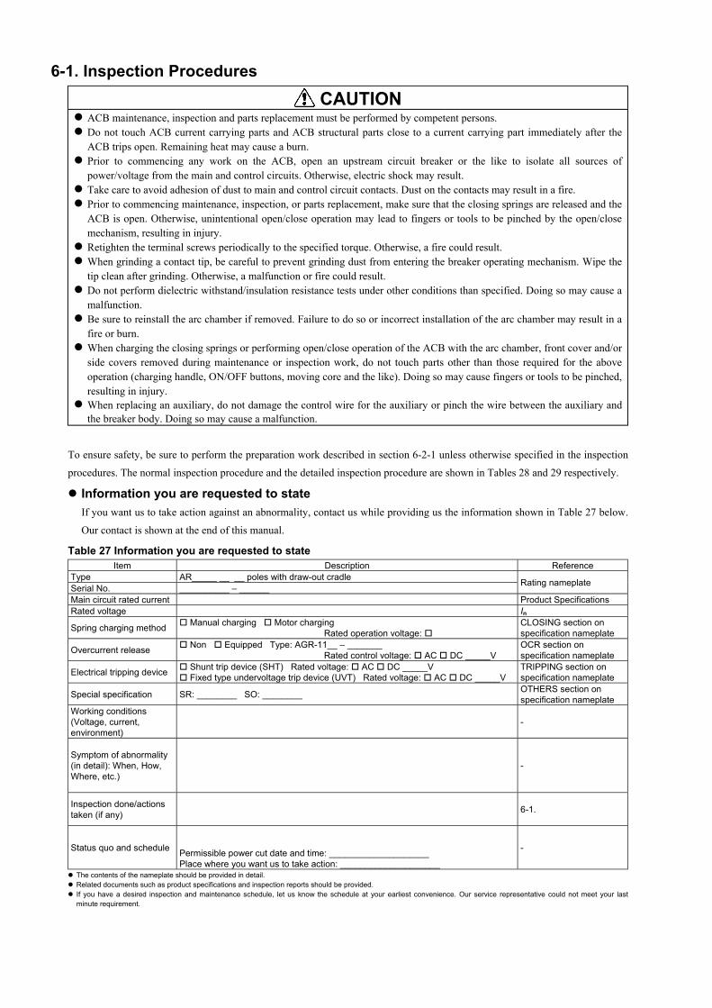
6-1. Inspection Procedures CAUTION
ACB maintenance, inspection and parts replacement must be performed by competent persons. Do not touch ACB current carrying parts and ACB structural parts close to a current carrying part immediately after theACB trips open. Remaining heat may cause a burn.
Prior to commencing any work on the ACB, open an upstream circuit breaker or the like to isolate all sources ofpower/voltage from the main and control circuits. Otherwise, electric shock may result.
Take care to avoid adhesion of dust to main and control circuit contacts. Dust on the contacts may result in a fire. Prior to commencing maintenance, inspection, or parts replacement, make sure that the closing springs are released and theACB is open. Otherwise, unintentional open/close operation may lead to fingers or tools to be pinched by the open/closemechanism, resulting in injury.
Retighten the terminal screws periodically to the specified torque. Otherwise, a fire could result. When grinding a contact tip, be careful to prevent grinding dust from entering the breaker operating mechanism. Wipe thetip clean after grinding. Otherwise, a malfunction or fire could result.
Do not perform dielectric withstand/insulation resistance tests under other conditions than specified. Doing so may cause amalfunction.
Be sure to reinstall the arc chamber if removed. Failure to do so or incorrect installation of the arc chamber may result in afire or burn.
When charging the closing springs or performing open/close operation of the ACB with the arc chamber, front cover and/orside covers removed during maintenance or inspection work, do not touch parts other than those required for the aboveoperation (charging handle, ON/OFF buttons, moving core and the like). Doing so may cause fingers or tools to be pinched,resulting in injury.
When replacing an auxiliary, do not damage the control wire for the auxiliary or pinch the wire between the auxiliary andthe breaker body. Doing so may cause a malfunction.
To ensure safety, be sure to perform the preparation work described in section 6-2-1 unless otherwise specified in the inspection
procedures. The normal inspection procedure and the detailed inspection procedure are shown in Tables 28 and 29 respectively.
Information you are requested to stateIf you want us to take action against an abnormality, contact us while providing us the information shown in Table 27 below.
Our contact is shown at the end of this manual.
Table 27 Information you are requested to stateItem Description Reference
Type AR_____ __ __ poles with draw-out cradleSerial No. __________ – ______ Rating nameplate
Main circuit rated current Product SpecificationsRated voltage In
Spring charging method Manual charging Motor chargingRated operation voltage:
CLOSING section onspecification nameplate
Overcurrent release Non Equipped Type: AGR-11__ – _______Rated control voltage: AC DC _____V
OCR section onspecification nameplate
Electrical tripping device Shunt trip device (SHT) Rated voltage: AC DC _____V Fixed type undervoltage trip device (UVT) Rated voltage: AC DC _____V
TRIPPING section onspecification nameplate
Special specification SR: ________ SO: ________ OTHERS section onspecification nameplate
Working conditions(Voltage, current,environment)
-
Symptom of abnormality(in detail): When, How,Where, etc.)
-
Inspection done/actionstaken (if any) 6-1.
Status quo and schedule Permissible power cut date and time: ____________________Place where you want us to take action: ____________________
-
The contents of the nameplate should be provided in detail. Related documents such as product specifications and inspection reports should be provided. If you have a desired inspection and maintenance schedule, let us know the schedule at your earliest convenience. Our service representative could not meet your lastminute requirement.
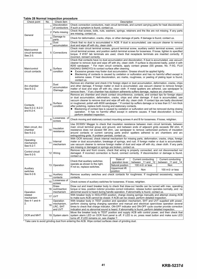
KRB-5237d41
Table 28 Normal inspection procedureCheck point No. Check item Description
1 Discolorationof conductors
Check connection conductors, main circuit terminals, and current carrying parts for heat discoloration.If such a symptom is found, contact us.
2 Parts missing Check that screws, bolts, nuts, washers, springs, retainers and the like are not missing. If any partsare missing, contact us.
3 Damage toparts Check for deformation, cracks, chips, or other damage of parts. If damage is found, contact us.
General
4 Dustaccumulation
Check that no dust is accumulated in ACB. If dust is accumulated, use vacuum cleaner to removedust and wipe off with dry, clean cloth.
Main/controlcircuit terminalsSee 2-3.
5 Connections
Check main circuit terminal screws, ground terminal screw, auxiliary switch terminal screws, controlcircuit terminal screws, and position switch terminal screws for looseness. If loose, tighten to specifiedtorque. If #187 tab terminals are used, check that receptacle terminals are inserted correctly. Ifincorrect, reinsert correctly.
Main/controlcircuit contacts 6 Surface
condition
Check that contacts have no dust accumulation and discoloration. If dust is accumulated, use vacuumcleaner to remove dust and wipe off with dry, clean cloth. If surface is discolored badly, polish it with#200 sandpaper. * For main circuit contacts, apply contact grease (SS grease, No. F-5G, FUJIKAGAKU SANGYO) to contact surface after cleaning.
Excessive grease may foster dust accumulation. Grease should be applied lightly. Blackening of contacts is caused by oxidation or sulfuration and has no harmful effect except in
extreme cases. If heat discoloration, arc marks, roughness, or peeling of plating layer is found,contact us.
Arc chamberSee 6-2-2. 7
Dustaccumulation/Damage
Remove arc chamber and check it for foreign object or dust accumulation, deformation, cracks, chipsand other damage. If foreign matter or dust is accumulated, use vacuum cleaner to remove foreignmatter of dust and wipe off with dry, clean cloth. If metal spatters are adhered, use sandpaper toremove them. * If arc chamber has stubborn adherents suffers damage, replace arc chamber.
8 Surfacecondition
Remove arc chamber and check contact circumference, contacts, and contact tips for foreign objector dust accumulation, deformation, cracks, chips and other damage. If dust is accumulated, usevacuum cleaner to remove dust and wipe off with dry, clean cloth. If contact tips are badly discoloredor roughened, polish with #200 sandpaper. * If contact tip suffers damage or is less than 0.7 mm thickafter polishing, replace both moving and stationary contacts.
Blackening of contact tips is caused by oxidation or sulfuration and will be removed during closingoperation. It has no harmful effect except in extreme causes. If heat discoloration is found,perform detailed inspection.
ContactsSee 6-2-2, 6-2-3and 6-2-4.
9 Looseness ofscrews Check moving and stationary contact mounting screws A and B for looseness. If loose, retighten.
Main circuit, ArcchamberSee 6-2-2.
10 Insulationresistance
Use DC500V Megger to check that insulation resistance between main circuit terminals, betweenmain circuit terminal group and ground, and between ends of adjacent grids exceeds 5M ohm. Ifresistance does not exceed 5M ohm, use sandpaper to remove carbonized portions of insulationaround contacts or current carrying parts and/or spatters adhered to arc chambers and arcextinguishing grids. If problem persists, contact us.
OperatingmechanismSee 6-2-7.
11 Internalmechanism
With OCR removed, check internal mechanism for missing parts, deformation, cracks, chips, foreignmater or dust accumulation, breakage of springs, and rust. If foreign matter or dust is accumulated,use vacuum cleaner to remove foreign matter of dust and wipe off with dry, clean cloth. If any partsare missing or damaged or springs are broken, contact us.
Control circuitSee 6-2-5. 12 Wiring
Remove side and front covers, check that wiring is properly connected, and not disconnected nordamaged. If incorrect connection is found, connect correctly. If disconnection or damage is found,contact us.
State ofoperation lever
Current conductingbetween _11 and _12
Current conductingbetween _11 and _14
Natural position 100 mΩ or less Non13 OperationCheck that auxiliary switchesoperate as shown to the right. If not so, replace switches. Uppermost lift
position Non 100 mΩ or less
14 Auxiliarycontacts
Remove auxiliary switches and check contacts for roughness. If roughened excessively, replacecontacts.
AuxiliaryswitchesSee 6-2-9.
15 Looseness ofscrews Check screws of auxiliary switches for looseness. If loose, retighten.
16Draw-out/insertionmechanism
Draw out and insert breaker body to check that draw-out handle can be turned with max. operatingtorque or less, position indictor provides correct indication, release button operates normally, and noabnormal sound is heard during handle operation. If abnormality is found, contact us.
17 UVT With breaker body in ISOLATED position, charge closing springs manually and attempt closing ACBto make sure ACB cannot be closed. If ACB can be closed, perform detailed inspection.
OperationrelatedmechanismSee 4-1 and 4-2. 18
Operationmechanism,LRC, SHTand UVT
With breaker body in TEST position and operation mechanism, SHT and UVT supplied with power,perform closing spring charging operation and manual and electrical open/close operation severaltimes to check that charge indicator, ON-OFF indicator and ON-OFF cycle counter provide correctionindication and no abnormal sound is heard. If abnormality is found, perform detailed inspection.
OCR and MHT 19 System alarmMove the breaker body to TEST position and supply ACB with control power, and then check thatsystem alarm LED on OCR front panel is off. If LED is on, press reset button and make sure LEDturns off. If LED remains on, see chapter 7.
* Take care to avoid grinding dust from entering the ACB. Wipe contact surfaces clean of grinding dust.
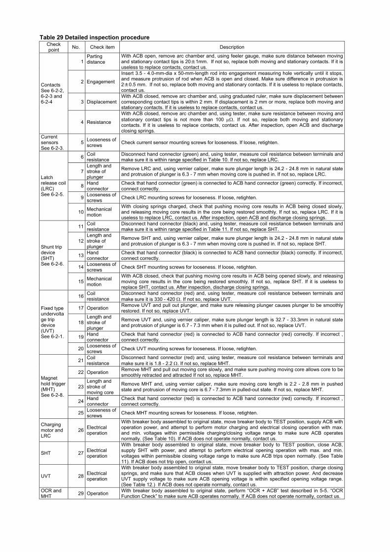
Table 29 Detailed inspection procedureCheckpoint No. Check item Description
1Partingdistance
With ACB open, remove arc chamber and, using feeler gauge, make sure distance between movingand stationary contact tips is 20±1mm. If not so, replace both moving and stationary contacts. If it isuseless to replace contacts, contact us.
2 Engagement
Insert 3.5 - 4.0-mm-dia x 50-mm-length rod into engagement measuring hole vertically until it stops,and measure protrusion of rod when ACB is open and closed. Make sure difference in protrusion is2±0.5 mm. If not so, replace both moving and stationary contacts. If it is useless to replace contacts,contact us.
3 DisplacementWith ACB closed, remove arc chamber and, using graduated ruler, make sure displacement betweencorresponding contact tips is within 2 mm. If displacement is 2 mm or more, replace both moving andstationary contacts. If it is useless to replace contacts, contact us.
ContactsSee 6-2-2,6-2-3 and6-2-4
4 Resistance
With ACB closed, remove arc chamber and, using tester, make sure resistance between moving andstationary contact tips is not more than 100 µΩ. If not so, replace both moving and stationarycontacts. If it is useless to replace contacts, contact us. After inspection, open ACB and dischargeclosing springs.
CurrentsensorsSee 6-2-3.
5 Looseness ofscrews Check current sensor mounting screws for looseness. If loose, retighten.
6 Coilresistance
Disconnect hand connector (green) and, using tester, measure coil resistance between terminals andmake sure it is within range specified in Table 10. If not so, replace LRC.
7Length andstroke ofplunger
Remove LRC and, using vernier caliper, make sure plunger length is 24.2 - 24.8 mm in natural stateand protrusion of plunger is 6.3 - 7 mm when moving core is pushed in. If not so, replace LRC.
8 Handconnector
Check that hand connector (green) is connected to ACB hand connector (green) correctly. If incorrect,connect correctly.
9 Looseness ofscrews Check LRC mounting screws for looseness. If loose, retighten.
Latchrelease coil(LRC)See 6-2-5.
10 Mechanicalmotion
With closing springs charged, check that pushing moving core results in ACB being closed slowly,and releasing moving core results in the core being restored smoothly. If not so, replace LRC. If it isuseless to replace LRC, contact us. After inspection, open ACB and discharge closing springs.
11 Coilresistance
Disconnect hand connector (black) and, using tester, measure coil resistance between terminals andmake sure it is within range specified in Table 11. If not so, replace SHT.
12Length andstroke ofplunger
Remove SHT and, using vernier caliper, make sure plunger length is 24.2 - 24.8 mm in natural stateand protrusion of plunger is 6.3 - 7 mm when moving core is pushed in. If not so, replace SHT.
13 Handconnector
Check that hand connector (black) is connected to ACB hand connector (black) correctly. If incorrect,connect correctly.
14 Looseness ofscrews Check SHT mounting screws for looseness. If loose, retighten.
Shunt tripdevice(SHT)See 6-2-6.
15 Mechanicalmotion
With ACB closed, check that pushing moving core results in ACB being opened slowly, and releasingmoving core results in the core being restored smoothly. If not so, replace SHT. If it is useless toreplace SHT, contact us. After inspection, discharge closing springs.
16 Coilresistance
Disconnect hand connector (red) and, using tester, measure coil resistance between terminals andmake sure it is 330 - 420 Ω. If not so, replace UVT.
17 Operation Remove UVT and pull out plunger, and make sure releasing plunger causes plunger to be smoothlyrestored. If not so, replace UVT.
18Length andstroke ofplunger
Remove UVT and, using vernier caliper, make sure plunger length is 32.7 - 33.3mm in natural stateand protrusion of plunger is 6.7 - 7.3 mm when it is pulled out. If not so, replace UVT.
19 Handconnector
Check that hand connector (red) is connected to ACB hand connector (red) correctly. If incorrect ,connect correctly.
Fixed typeundervoltage tripdevice(UVT)See 6-2-1.
20 Looseness ofscrews Check UVT mounting screws for looseness. If loose, retighten.
21 Coilresistance
Disconnect hand connector (red) and, using tester, measure coil resistance between terminals andmake sure it is 1.8 - 2.2 Ω. If not so, replace MHT.
22 Operation Remove MHT and pull out moving core slowly, and make sure pushing moving core allows core to besmoothly retracted and attracted If not so, replace MHT.
23Length andstroke ofmoving core
Remove MHT and, using vernier caliper, make sure moving core length is 2.2 - 2.8 mm in pushedstate and protrusion of moving core is 6.7 - 7.3mm in pulled-out state. If not so, replace MHT.
24 Handconnector
Check that hand connector (red) is connected to ACB hand connector (red) correctly. If incorrect ,connect correctly.
Magnethold trigger(MHT)See 6-2-8.
25 Looseness ofscrews Check MHT mounting screws for looseness. If loose, retighten.
Chargingmotor andLRC
26 Electricaloperation
With breaker body assembled to original state, move breaker body to TEST position, supply ACB withoperation power, and attempt to perform motor charging and electrical closing operation with max.and min. voltages within permissible charging/closing voltage range to make sure ACB operatesnormally. (See Table 10). If ACB does not operate normally, contact us.
SHT 27 Electricaloperation
With breaker body assembled to original state, move breaker body to TEST position, close ACB,supply SHT with power, and attempt to perform electrical opening operation with max. and min.voltages within permissible closing voltage range to make sure ACB trips open normally. (See Table11). If ACB does not trip open, contact us.
UVT 28 Electricaloperation
With breaker body assembled to original state, move breaker body to TEST position, charge closingsprings, and make sure that ACB closes when UVT is supplied with attraction power. And decreaseUVT supply voltage to make sure ACB opening voltage is within specified opening voltage range.(See Table 12.) If ACB does not operate normally, contact us.
OCR andMHT 29 Operation With breaker body assembled to original state, perform “OCR + ACB” test described in 5-5. “OCR
Function Check” to make sure ACB operates normally. If ACB does not operate normally, contact us.
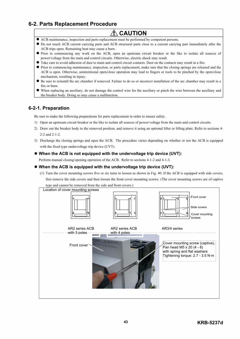
6-2. Parts Replacement Procedure CAUTION
ACB maintenance, inspection and parts replacement must be performed by competent persons. Do not touch ACB current carrying parts and ACB structural parts close to a current carrying part immediately after theACB trips open. Remaining heat may cause a burn.
Prior to commencing any work on the ACB, open an upstream circuit breaker or the like to isolate all sources ofpower/voltage from the main and control circuits. Otherwise, electric shock may result.
Take care to avoid adhesion of dust to main and control circuit contacts. Dust on the contacts may result in a fire. Prior to commencing maintenance, inspection, or parts replacement, make sure that the closing springs are released and theACB is open. Otherwise, unintentional open/close operation may lead to fingers or tools to be pinched by the open/closemechanism, resulting in injury.
Be sure to reinstall the arc chamber if removed. Failure to do so or incorrect installation of the arc chamber may result in afire or burn.
When replacing an auxiliary, do not damage the control wire for the auxiliary or pinch the wire between the auxiliary andthe breaker body. Doing so may cause a malfunction.
6-2-1. PreparationBe sure to make the following preparations for parts replacement in order to ensure safety.
1) Open an upstream circuit breaker or the like to isolate all sources of power/voltage from the main and control circuits.
2) Draw out the breaker body to the removed position, and remove it using an optional lifter or lifting plate. Refer to sections 4-
2-2 and 2-1-2.
3) Discharge the closing springs and open the ACB. The procedure varies depending on whether or not the ACB is equipped
with the fixed type undervoltage trip device (UVT).
When the ACB is not equipped with the undervoltage trip device (UVT): Perform manual closing/opening operation of the ACB. Refer to sections 4-1-2 and 4-1-3.
When the ACB is equipped with the undervoltage trip device (UVT): (1) Turn the cover mounting screws five or six turns to loosen as shown in Fig. 40. If the ACB is equipped with side covers,
first remove the side covers and then loosen the front cover mounting screws. (The cover mounting screws are of captive
type and cannot be removed from the side and front covers.) Location of cover mounting screws
AR3/4 series
Front cover
Side covers
Cover mountingscrews
AR2 series ACBwith 3 poles
Fig. 4
Front cover
AR2 series ACBwith 4 poles
KRB-5237d43
0 Cover mounting screws
Cover mounting screw (captive),Pan head M5 x 20 (4 - 8)with spring and flat washersTightening torque: 2.7 - 3.5 N·m
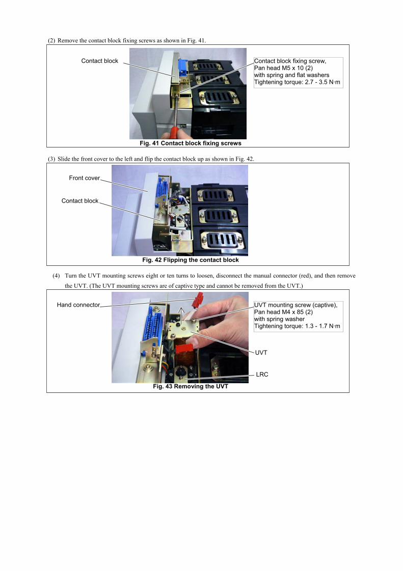
(2) Remove the contact block fixing screws as shown in Fig. 41.
Fig. 41 Contact block fixing screws
(3) Slide the front cover to the left and flip the contact block up as shown in Fig. 42.
Fig. 42 Flipping the contact block
(4) Turn the UVT mounting screws eight or ten turns to loosen, disconnect the manual connector (red), and then remove
the UVT. (The UVT mounting screws are of captive type and cannot be removed from the UVT.)
Fig. 43 Removing the UVT
Contact block Contact block fixing screw,Pan head M5 x 10 (2)with spring and flat washersTightening torque: 2.7 - 3.5 N·m
Front cover
Contact block
UVT mounting screw (captive),Pan head M4 x 85 (2)with spring washerTightening torque: 1.3 - 1.7 N·m
Hand connector
UVT
LRC
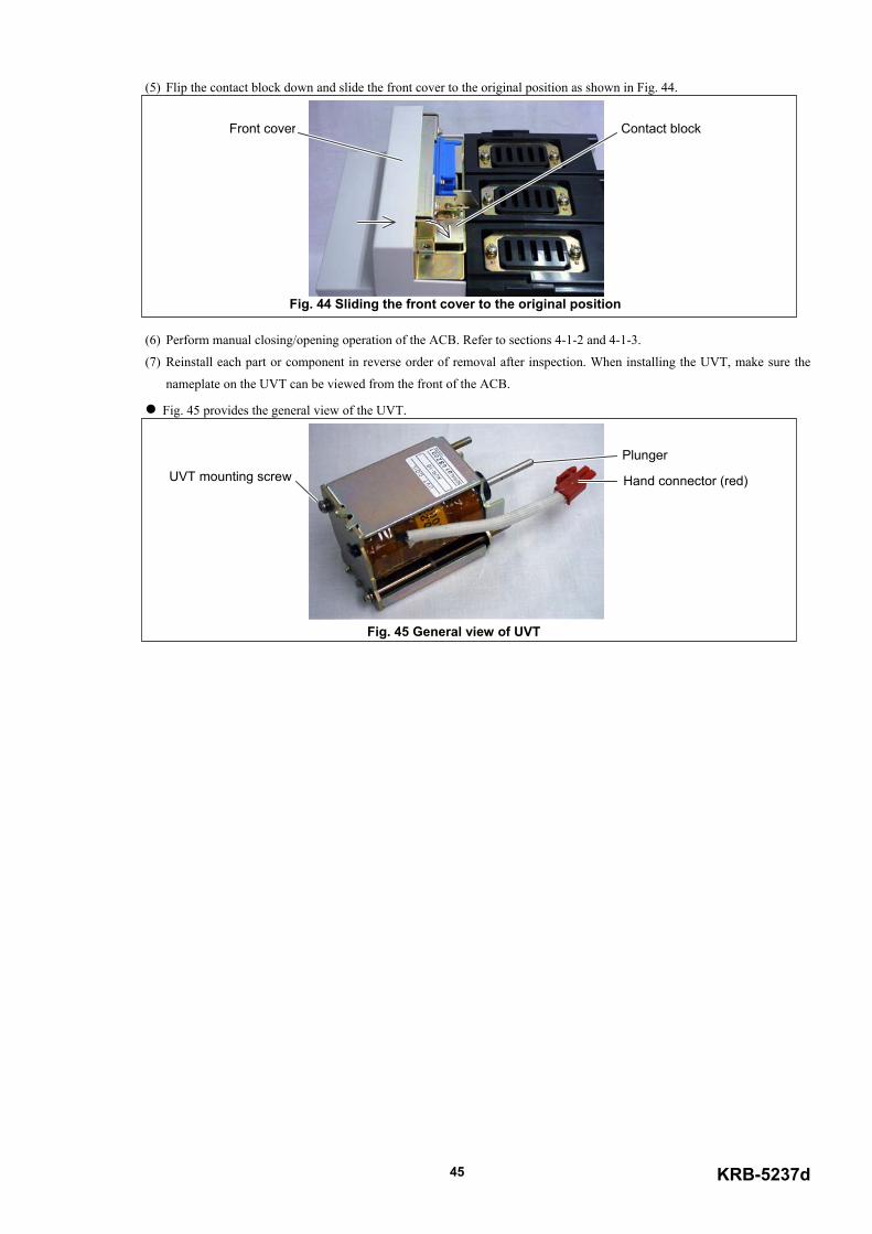
KRB-5237d45
(5) Flip the contact block down and slide the front cover to the original position as shown in Fig. 44.
Fig. 44 Sliding the front cover to the original position
(6) Perform manual closing/opening operation of the ACB. Refer to sections 4-1-2 and 4-1-3.
(7) Reinstall each part or component in reverse order of removal after inspection. When installing the UVT, make sure the
nameplate on the UVT can be viewed from the front of the ACB.
Fig. 45 provides the general view of the UVT.
Fig. 45 General view of UVT
Plunger
Hand connector (red)UVT mounting screw
Contact blockFront cover
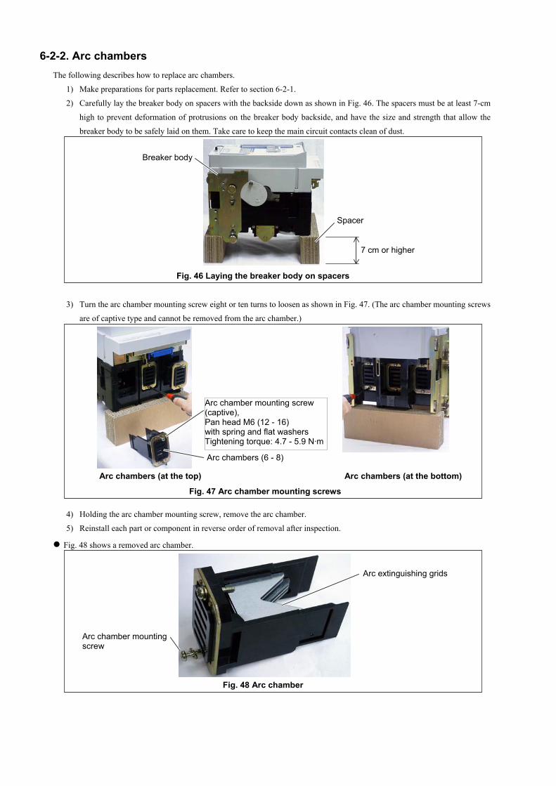
6-2-2. Arc chambersThe following describes how to replace arc chambers.
1) Make preparations for parts replacement. Refer to section 6-2-1.
2) Carefully lay the breaker body on spacers with the backside down as shown in Fig. 46. The spacers must be at least 7-cm
high to prevent deformation of protrusions on the breaker body backside, and have the size and strength that allow the
breaker body to be safely laid on them. Take care to keep the main circuit contacts clean of dust.
Fig. 46 Laying the breaker body on spacers
3) Turn the arc chamber mounting screw eight or ten turns to loosen as shown in Fig. 47. (The arc chamber mounting screws
are of captive type and cannot be removed from the arc chamber.)
Arc chambers (at the top) Arc chambers (at the bottom)
Fig. 47 Arc chamber mounting screws
4) Holding the arc chamber mounting screw, remove the arc chamber.
5) Reinstall each part or component in reverse order of removal after inspection.
Fig. 48 shows a removed arc chamber.
Fig. 48 Arc chamber
Arc chambers (6 - 8)
Arc chamber mounting screw(captive),Pan head M6 (12 - 16)with spring and flat washersTightening torque: 4.7 - 5.9 N·m
Spacer
7 cm or higher
Breaker body
Arc extinguishing grids
Arc chamber mountingscrew
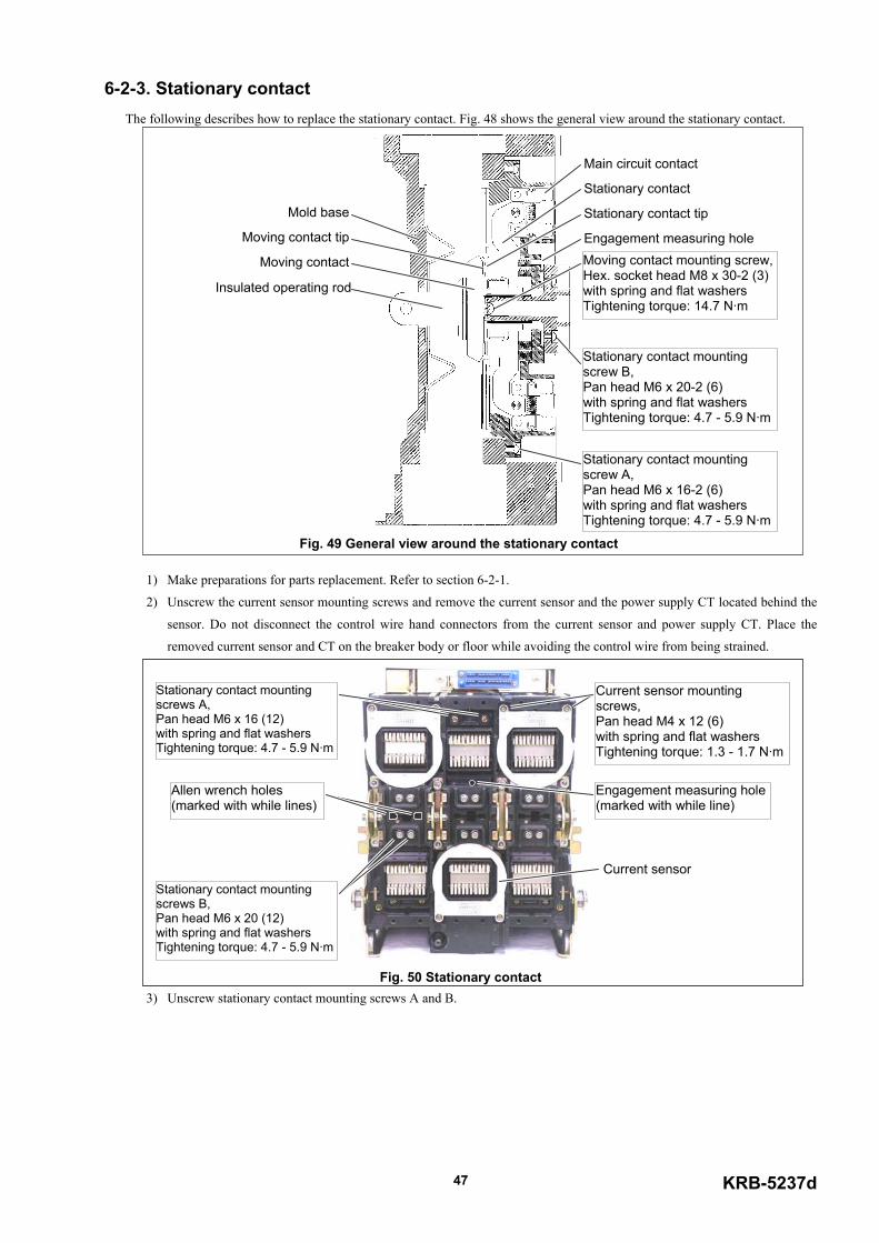
KRB-5237d47
6-2-3. Stationary contactThe following describes how to replace the stationary contact. Fig. 48 shows the general view around the stationary contact.
Fig. 49 General view around the stationary contact
1) Make preparations for parts replacement. Refer to section 6-2-1.
2) Unscrew the current sensor mounting screws and remove the current sensor and the power supply CT located behind the
sensor. Do not disconnect the control wire hand connectors from the current sensor and power supply CT. Place the
removed current sensor and CT on the breaker body or floor while avoiding the control wire from being strained.
Fig. 50 Stationary contact3) Unscrew stationary contact mounting screws A and B.
Main circuit contact
Stationary contact
Stationary contact tip
Moving contact tip
Moving contact
Insulated operating rod
Mold base
Engagement measuring holeMoving contact mounting screw,Hex. socket head M8 x 30-2 (3)with spring and flat washersTightening torque: 14.7 N·m
Stationary contact mountingscrew A,Pan head M6 x 16-2 (6)with spring and flat washersTightening torque: 4.7 - 5.9 N·m
Stationary contact mountingscrew B,Pan head M6 x 20-2 (6)with spring and flat washersTightening torque: 4.7 - 5.9 N·m
Current sensor mountingscrews,Pan head M4 x 12 (6)with spring and flat washersTightening torque: 1.3 - 1.7 N·m
Stationary contact mountingscrews A,Pan head M6 x 16 (12)with spring and flat washersTightening torque: 4.7 - 5.9 N·m
Stationary contact mountingscrews B,Pan head M6 x 20 (12)with spring and flat washersTightening torque: 4.7 - 5.9 N·m
Allen wrench holes(marked with while lines)
Engagement measuring hole(marked with while line)
Current sensor
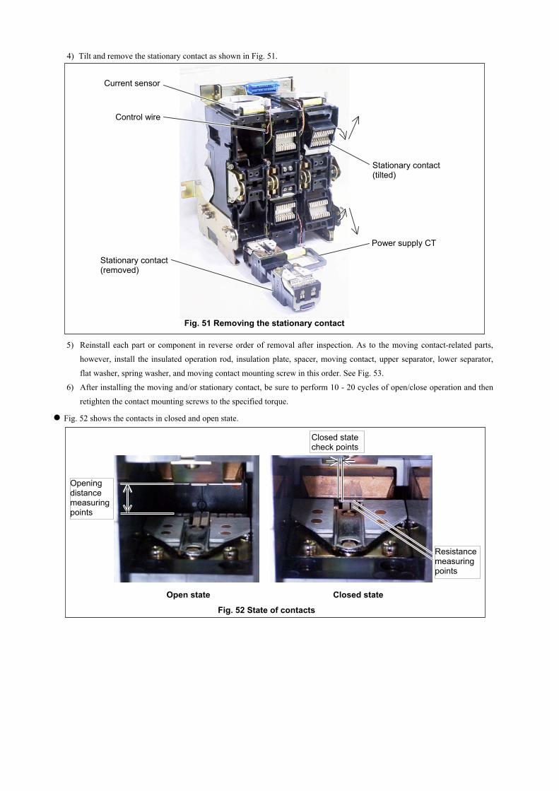
4) Tilt and remove the stationary contact as shown in Fig. 51.
Fig. 51 Removing the stationary contact
5) Reinstall each part or component in reverse order of removal after inspection. As to the moving contact-related parts,
however, install the insulated operation rod, insulation plate, spacer, moving contact, upper separator, lower separator,
flat washer, spring washer, and moving contact mounting screw in this order. See Fig. 53.
6) After installing the moving and/or stationary contact, be sure to perform 10 - 20 cycles of open/close operation and then
retighten the contact mounting screws to the specified torque.
Fig. 52 shows the contacts in closed and open state.
Open state Closed state
Fig. 52 State of contacts
Current sensor
Control wire
Stationary contact(removed)
Power supply CT
Stationary contact(tilted)
Openingdistancemeasuringpoints
Closed statecheck points
Resistancemeasuringpoints

KRB-5237d49
6-2-4. Moving contactThe following describes how to replace the moving contact.
1) Make preparations for parts replacement. Refer to section 6-2-1.
2) Remove the arc chambers and stationary contact. Refer to sections 6-2-2 and 6-2-3.
3) Insert an Allen wrench of a nominal diameter of 5 into each of the Allen wrench holes shown in Fig. 50, turn each
moving contact mounting screw two or three turns to loosen, and raise and remove the upper separator shown in Fig. 53.
Fig. 54 Moving contact
4) Supporting the spacers (the number of which varies depending on the poles), the moving contact, the lower separator, and
the moving contact mounting screws by hand, turn the moving contact mounting screws additional two or three turns to
remove these parts. Fig. 54 shows the moving contact-related parts.
Fig. 54 Moving contact-related parts
5) Reinstall each part or component in reverse order of removal after inspection. As to the moving contact-related parts,
however, install the insulated operation rod, insulation plate, spacer, moving contact, upper separator, lower separator,
flat washer, spring washer, and moving contact mounting screw in this order. See Fig. 53.
6) After installing the moving and/or stationary contact, be sure to perform 10 - 20 cycles of open/close operation and then
retighten the contact mounting screws to the specified torque.
Lower separator
Upper separatorMoving contact tip
Moving contact
Insulated operating rod
Spacer
Moving contact mountingscrew,Hex. socket head M8 x 30-6 (8)with spring and flat washersTightening torque: 14.7 N·m
Lower separator
Upper separatorMoving contact
Spacer
Moving contactmounting screw
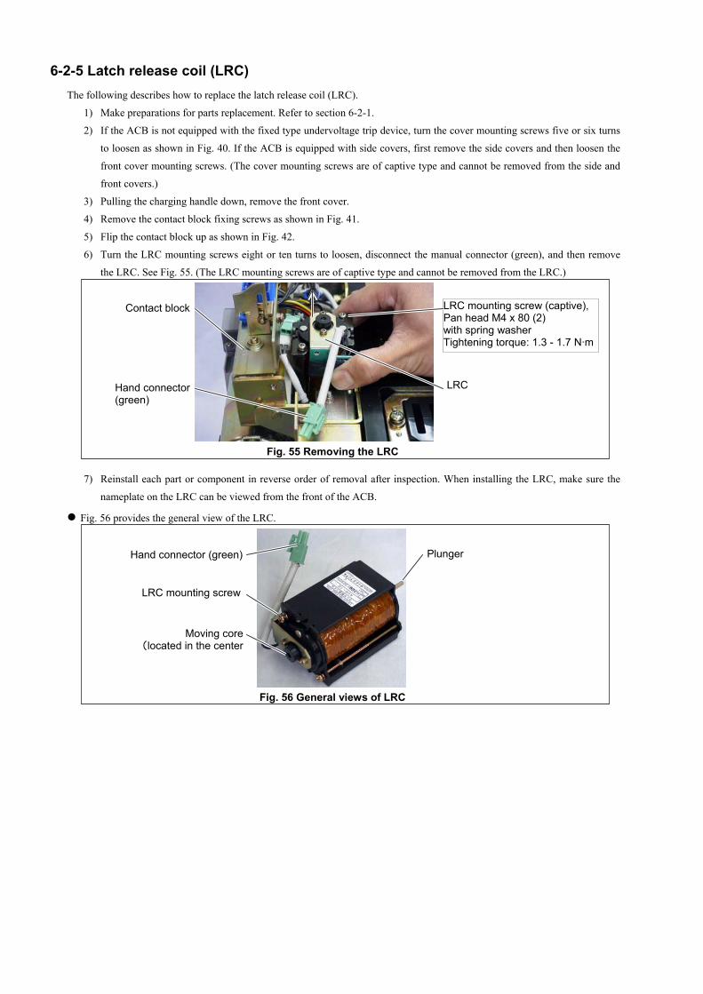
6-2-5 Latch release coil (LRC)The following describes how to replace the latch release coil (LRC).
1) Make preparations for parts replacement. Refer to section 6-2-1.
2) If the ACB is not equipped with the fixed type undervoltage trip device, turn the cover mounting screws five or six turns
to loosen as shown in Fig. 40. If the ACB is equipped with side covers, first remove the side covers and then loosen the
front cover mounting screws. (The cover mounting screws are of captive type and cannot be removed from the side and
front covers.)
3) Pulling the charging handle down, remove the front cover.
4) Remove the contact block fixing screws as shown in Fig. 41.
5) Flip the contact block up as shown in Fig. 42.
6) Turn the LRC mounting screws eight or ten turns to loosen, disconnect the manual connector (green), and then remove
the LRC. See Fig. 55. (The LRC mounting screws are of captive type and cannot be removed from the LRC.)
Fig. 55 Removing the LRC
7) Reinstall each part or component in reverse order of removal after inspection. When installing the LRC, make sure the
nameplate on the LRC can be viewed from the front of the ACB.
Fig. 56 provides the general view of the LRC.
PlungerHand connector (green)
M(located i
LRC mounting screw
LRC
Contact block LRC mounting screw (captive),Pan head M4 x 80 (2)with spring washerTightening torque: 1.3 - 1.7 N·m
Hand connector(green)
oving coren the center
)
Fig. 56 General views of LRC
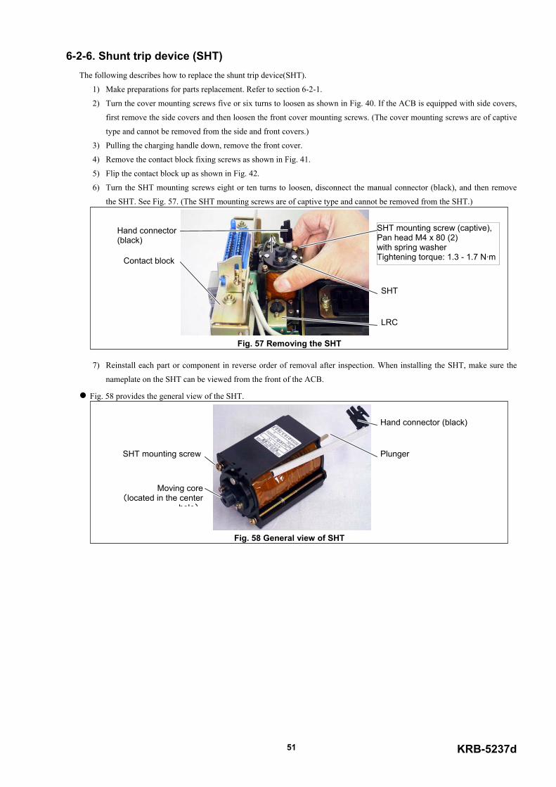
6-2-6. Shunt trip device (SHT)The following describes how to replace the shunt trip device(SHT).
1) Make preparations for parts replacement. Refer to section 6-2-1.
2) Turn the cover mounting screws five or six turns to loosen as shown in Fig. 40. If the ACB is equipped with side covers,
first remove the side covers and then loosen the front cover mounting screws. (The cover mounting screws are of captive
type and cannot be removed from the side and front covers.)
3) Pulling the charging handle down, remove the front cover.
4) Remove the contact block fixing screws as shown in Fig. 41.
5) Flip the contact block up as shown in Fig. 42.
6) Turn the SHT mounting screws eight or ten turns to loosen, disconnect the manual connector (black), and then remove
the SHT. See Fig. 57. (The SHT mounting screws are of captive type and cannot be removed from the SHT.)
Fig. 57 Removing the SHT
7) Reinstall each part or component in reverse order of removal after inspection. When installing the SHT, make sure the
nameplate on the SHT can be viewed from the front of the ACB.
Fig. 58 provides the general view of the SHT.
Plunger
Hand connector (black)
(located i
SHT mounting screw
Hand connector(black)
Contact block
SHT mounting screw (captive),Pan head M4 x 80 (2)with spring washerTightening torque: 1.3 - 1.7 N·m
SHT
LRC
Moving coren the center
hole)
KRB-5237d51
Fig. 58 General view of SHT
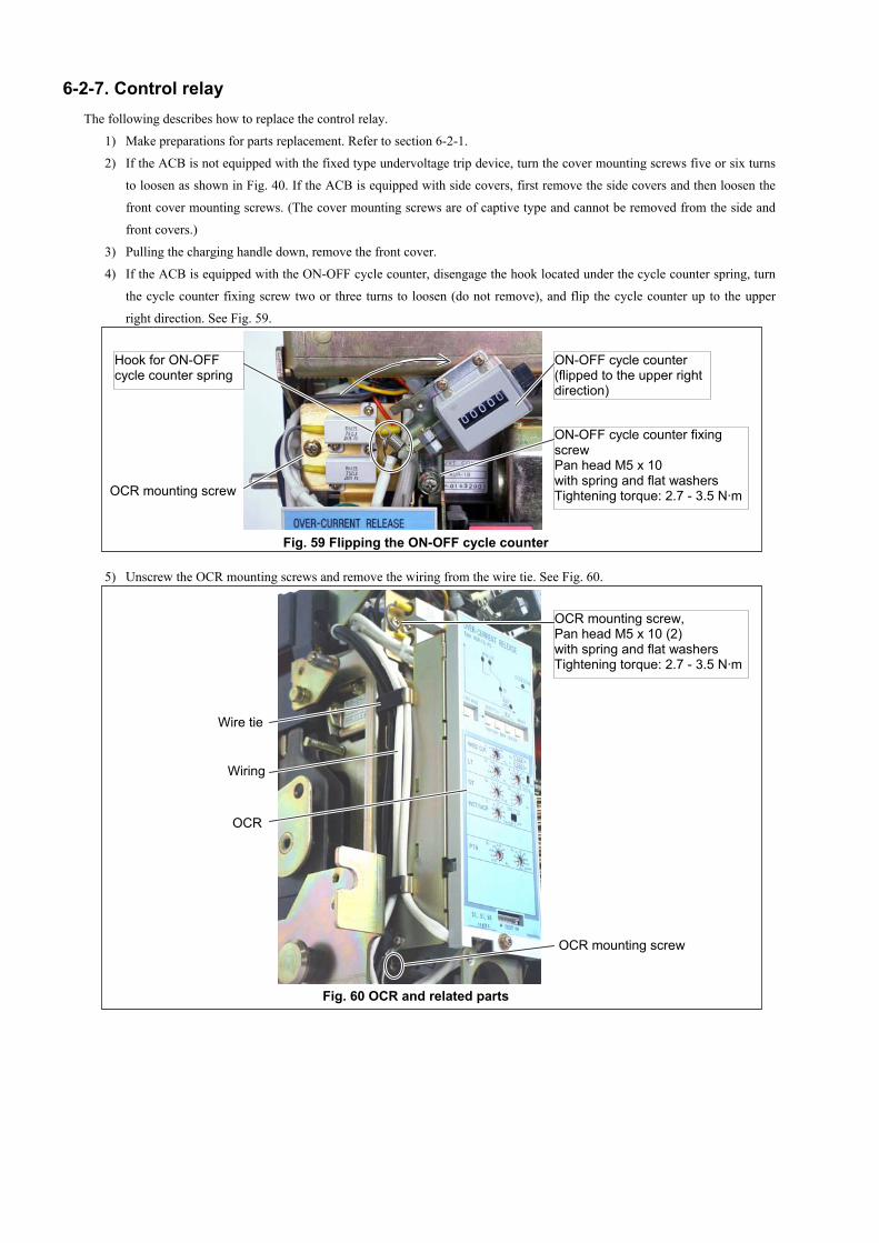
6-2-7. Control relayThe following describes how to replace the control relay.
1) Make preparations for parts replacement. Refer to section 6-2-1.
2) If the ACB is not equipped with the fixed type undervoltage trip device, turn the cover mounting screws five or six turns
to loosen as shown in Fig. 40. If the ACB is equipped with side covers, first remove the side covers and then loosen the
front cover mounting screws. (The cover mounting screws are of captive type and cannot be removed from the side and
front covers.)
3) Pulling the charging handle down, remove the front cover.
4) If the ACB is equipped with the ON-OFF cycle counter, disengage the hook located under the cycle counter spring, turn
the cycle counter fixing screw two or three turns to loosen (do not remove), and flip the cycle counter up to the upper
right direction. See Fig. 59.
Fig. 59 Flipping the ON-OFF cycle counter
5) Unscrew the OCR mounting screws and remove the wiring from the wire tie. See Fig. 60.
Fig. 60 OCR and related parts
ON-OFF cycle counter fixingscrewPan head M5 x 10with spring and flat washersTightening torque: 2.7 - 3.5 N·m
ON-OFF cycle counter(flipped to the upper rightdirection)
OCR mounting screw
Hook for ON-OFFcycle counter spring
Wire tie
Wiring
OCR mounting screw,Pan head M5 x 10 (2)with spring and flat washersTightening torque: 2.7 - 3.5 N·m
OCR
OCR mounting screw
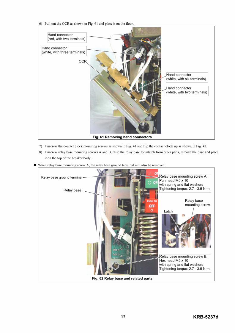
KRB-5237d53
6) Pull out the OCR as shown in Fig. 61 and place it on the floor.
Fig. 61 Removing hand connectors
7) Unscrew the contact block mounting screws as shown in Fig. 41 and flip the contact clock up as shown in Fig. 42.
8) Unscrew relay base mounting screws A and B, raise the relay base to unlatch from other parts, remove the base and place
it on the top of the breaker body.
When relay base mounting screw A, the relay base ground terminal will also be removed.
Fig. 62 Relay base and related parts
Hand connector(white, with six terminals)
Hand connector(white, with two terminals)
Hand connector(white, with three terminals)
Hand connector(red, with two terminals)
OCR
Relay base mounting screw A,Pan head M5 x 10with spring and flat washersTightening torque: 2.7 - 3.5 N·m
Relay base ground terminal
Relay base
Relay base mounting screw B,Hex head M5 x 10with spring and flat washersTightening torque: 2.7 - 3.5 N·m
Relay basemounting screw
Latch
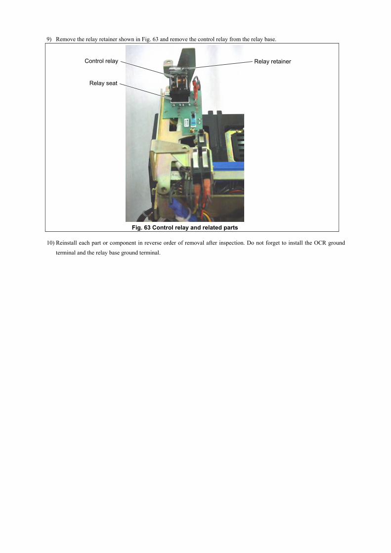
9) Remove the relay retainer shown in Fig. 63 and remove the control relay from the relay base.
Fig. 63 Control relay and related parts
10) Reinstall each part or component in reverse order of removal after inspection. Do not forget to install the OCR ground
terminal and the relay base ground terminal.
Relay retainerControl relay
Relay seat
スプリングチャージスイッチ
内部補助スイッチa接点
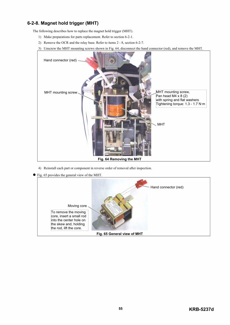
KRB-5237d55
6-2-8. Magnet hold trigger (MHT)The following describes how to replace the magnet hold trigger (MHT).
1) Make preparations for parts replacement. Refer to section 6-2-1.
2) Remove the OCR and the relay base. Refer to items 2 - 8, section 6-2-7.
3) Unscrew the MHT mounting screws shown in Fig. 64, disconnect the hand connector (red), and remove the MHT.
Fig. 64 Removing the MHT
4) Reinstall each part or component in reverse order of removal after inspection.
Fig. 65 provides the general view of the MHT.
Fig. 65 General view of MHT
MHT mounting screw,Pan head M4 x 8 (2)with spring and flat washersTightening torque: 1.3 - 1.7 N·m
Hand connector (red)
MHT
MHT mounting screw
Hand connector (red)
Moving core
To remove the movingcore, insert a small rodinto the center hole onthe skew and, holdingthe rod, lift the core.
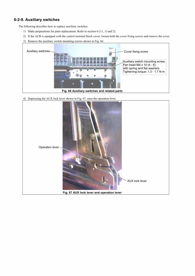
6-2-9. Auxiliary switchesThe following describes how to replace auxiliary switches.
1) Make preparations for parts replacement. Refer to section 6-2-1, 1) and 2).
2) If the ACB is equipped with the control terminal block cover, loosen both the cover fixing screws and remove the cover.
3) Remove the auxiliary switch mounting screws shown in Fig. 66.
Fig. 66 Auxiliary switches and related parts
4) Depressing the AUX lock lever shown in Fig. 67, raise the operation lever.
Fig. 67 AUX lock lever and operation lever
Auxiliary switches
Auxiliary switch mounting screw,Pan head M4 x 10 (4 - 6)with spring and flat washersTightening torque: 1.3 - 1.7 N·m
Cover fixing screw
AUX lock lever
Operation lever
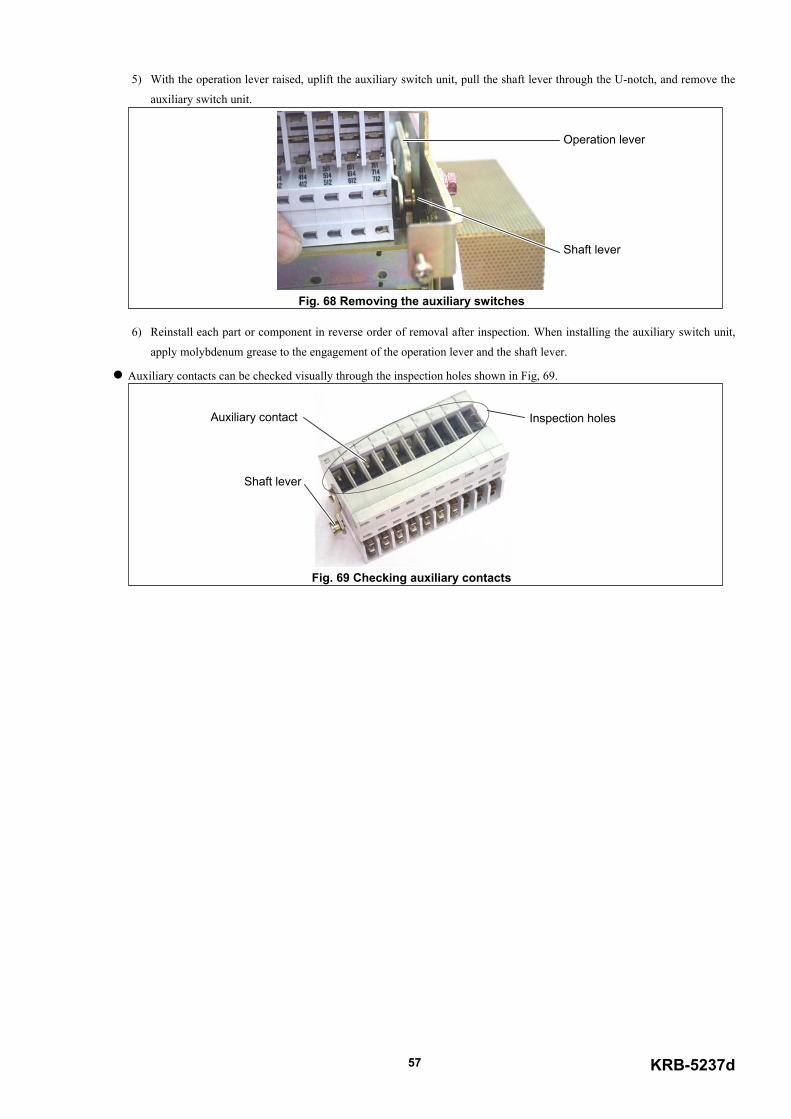
KRB-5237d57
5) With the operation lever raised, uplift the auxiliary switch unit, pull the shaft lever through the U-notch, and remove the
auxiliary switch unit.
Fig. 68 Removing the auxiliary switches
6) Reinstall each part or component in reverse order of removal after inspection. When installing the auxiliary switch unit,
apply molybdenum grease to the engagement of the operation lever and the shaft lever.
Auxiliary contacts can be checked visually through the inspection holes shown in Fig, 69.
Fig. 69 Checking auxiliary contacts
Operation lever
Shaft lever
Inspection holesAuxiliary contact
Shaft lever
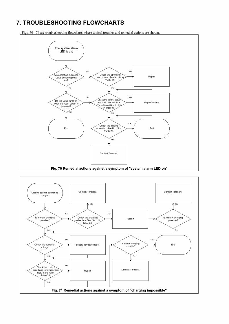
7. TROUBLESHOOTING FLOWCHARTSFigs. 70 - 74 are troubleshooting flowcharts where typical troubles and remedial actions are shown.
Fig. 70 Remedial actions against a symptom of "system alarm LED on"
Fig. 71 Remedial actions against a symptom of "charging impossible"
Yes
No
Is manual chargingpossible?
Closing springs cannot becharged
NG
Check the chargingmechanism. See No. 11 in
Table 28.
Repair
Contact Terasaki.
No
Is manual chargingpossible?
OK
Contact Terasaki.
Yes
OK
NG
Check the operationvoltage.
Supply correct voltage.
OK
NGCheck the control
circuit and terminals. SeeNos. 5 and 12 in
Table 28.
Repair
No
Yes
Is motor chargingpossible?
Contact Terasaki.
End
OK
NG
RepairCheck the operating
mechanism. See No. 11 inTable 28.
No
Are operation indicationLEDs excluding PTA
on?
Yes
Do the LEDs turns offwhen the reset button is
pressed?
End
Repair/replaceCheck the control circuitand MHT. See No. 12 inTable 28 and Nos. 21-25
in Table 29.
Check the trippingoperation. See No. 29 in
Table 29.End
Contact Terasaki.
The system alarmLED is on.
No
Yes
NG
OK
OK
NG
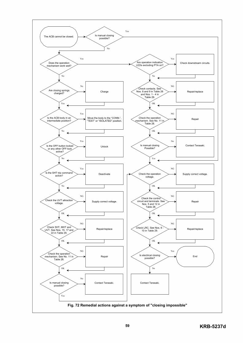
KRB-5237d59
Fig. 72 Remedial actions against a symptom of "closing impossible"
No
Yes
Is manual closingpossible?
The ACB cannot be closed.
No
Yes
Does the operationmechanism work well?
Yes
No
Are closing springscharged? Charge
OK
NG
Check the operationvoltage.
Supply correct voltage.
OK
NGCheck the control
circuit and terminals. SeeNos. 5 and 12 in
Table 28.
Repair
OK
NG
Check LRC. See Nos. 6 -10 in Table 29. Repair/replace
No
Yes
Is electrical closingpossible?
Contact Terasaki.
End
No
Yes
Are operation indicationLEDs excluding PTA on?
Check downstream circuits.
OK
NGCheck contacts. See
Nos. 8 and 9 in Table 28and Nos. 1 - 4 in
Table 29.
Repair/replace
OK
NG
Check the operationmechanism. See No. 11 in
Table 28.
Repair
Yes
No
Is manual closingPossible?
Contact Terasaki.
OK
NG
Check SHT, MHT andUVT. See Nos. 15, 17 and
22 in Table 29.Repair/replace
OK
NGCheck the operation
mechanism. See No. 11 inTable 28.
Repair
Yes
No
Is manual closingpossible?
No
Yes
Is the ACB body in anintermediate position?
Move the body to the “CONN.”,“TEST” or “ISOLATED” position.
No
Yes
Is the OFF button lockedor any other OFF-lock
active?
Unlock
No
Yes
Is the SHT trip commandactive? Deactivate
OK
NG
Check the UVT attractionvoltage. Supply correct voltage.
Contact Terasaki.
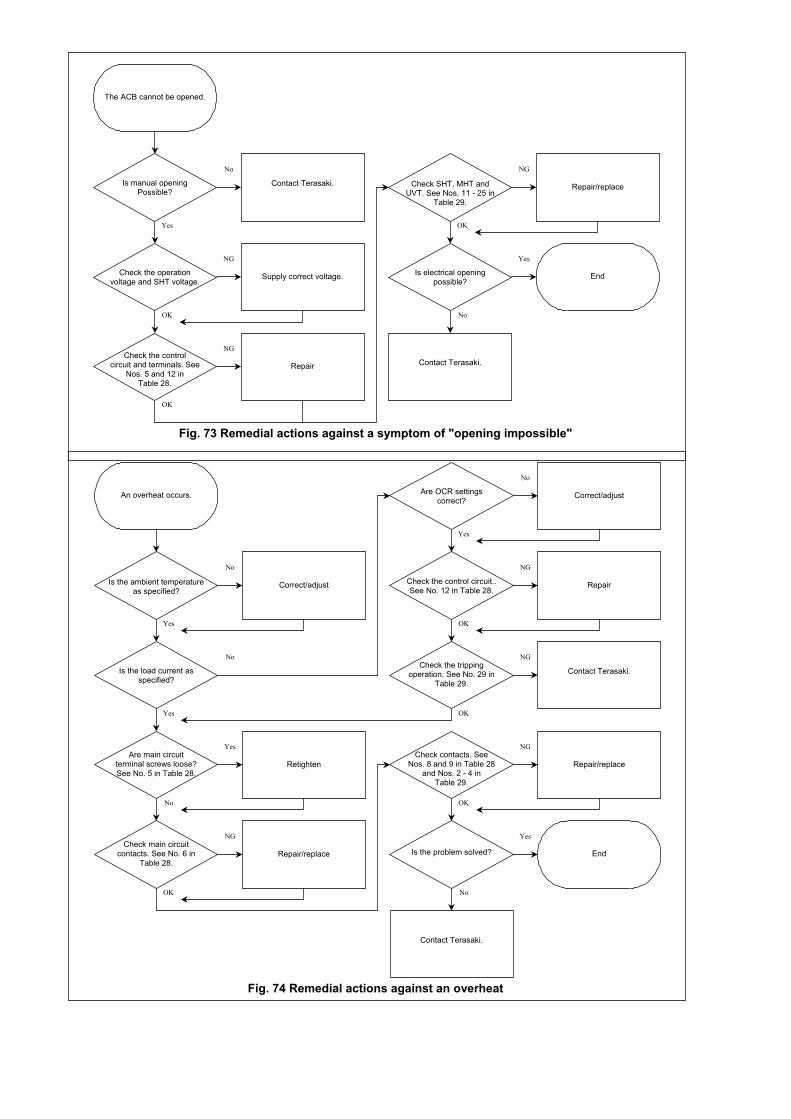
Fig. 73 Remedial actions against a symptom of "opening impossible"
Fig. 74 Remedial actions against an overheat
Yes
No
Is manual openingPossible?
Contact Terasaki.
The ACB cannot be opened.
OK
NG
Check the operationvoltage and SHT voltage. Supply correct voltage.
OK
NGCheck the control
circuit and terminals. SeeNos. 5 and 12 in
Table 28.
Repair
No
Yes
Is electrical openingpossible?
Contact Terasaki.
End
OK
NG
Check SHT, MHT andUVT. See Nos. 11 - 25 in
Table 29.
Repair/replace
Yes
No
Is the ambient temperatureas specified?
Correct/adjust
An overheat occurs.
Yes
No
Is the load current asspecified?
Yes
No
Are OCR settingscorrect? Correct/adjust
OK
NG
Check the control circuit..See No. 12 in Table 28.
Repair
OK
Check the trippingoperation. See No. 29 in
Table 29.
No
YesAre main circuit
terminal screws loose?See No. 5 in Table 28.
Retighten
OK
NGCheck main circuit
contacts. See No. 6 inTable 28.
Repair/replace
OK
NGCheck contacts. See
Nos. 8 and 9 in Table 28and Nos. 2 - 4 in
Table 29.
Repair/replace
No
Yes
Is the problem solved?
Contact Terasaki.
End
NG
Contact Terasaki.
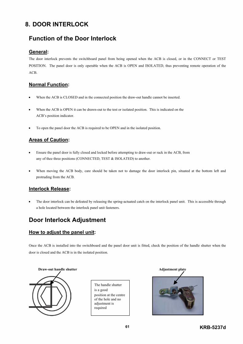
KRB-5237d61
8. DOOR INTERLOCK
Function of the Door Interlock
General:The door interlock prevents the switchboard panel from being opened when the ACB is closed, or in the CONNECT or TEST
POSITION. The panel door is only operable when the ACB is OPEN and ISOLATED, thus preventing remote operation of the
ACB.
Normal Function:
• When the ACB is CLOSED and in the connected position the draw-out handle cannot be inserted.
• When the ACB is OPEN it can be drawn-out to the test or isolated position. This is indicated on the
ACB’s position indicator.
• To open the panel door the ACB is required to be OPEN and in the isolated position.
Areas of Caution:
• Ensure the panel door is fully closed and locked before attempting to draw-out or rack in the ACB, from
any of thee three positions (CONNECTED, TEST & ISOLATED) to another.
• When moving the ACB body, care should be taken not to damage the door interlock pin, situated at the bottom left and
protruding from the ACB.
Interlock Release:
• The door interlock can be defeated by releasing the spring-actuated catch on the interlock panel unit. This is accessible through
a hole located between the interlock panel unit fasteners.
Door Interlock Adjustment
How to adjust the panel unit:
Once the ACB is installed into the switchboard and the panel door unit is fitted, check the position of the handle shutter when the
door is closed and the ACB is in the isolated position.
Draw-out handle shutter Adjustment plate
The handle shutteris a goodposition at the centreof the hole and noadjustment isrequired

KRB-5237d62
Door Interlock Outline Dimensions & Arrangement Drawings
When the handleshutter is at the left ofthe hole, remove theadjustment plate. Thiswill push against thehandle shutter lessmoving it towards thecentre of the hole.
When the handleshutter is at the right ofthe hole, turn theadjustment plate upsidedown with the doubleside to the top. This willpush against the handleshutter more moving ittowards the centre ofthe hole.
ACB FRONT COVER CENTRE LINE
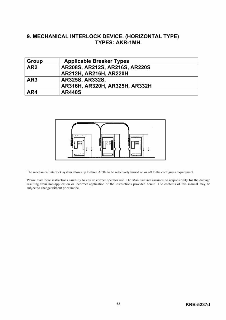
KRB-5237d63
9. MECHANICAL INTERLOCK DEVICE. (HORIZONTAL TYPE)TYPES: AKR-1MH.
Group Applicable Breaker TypesAR2 AR208S, AR212S, AR216S, AR220S
AR212H, AR216H, AR220HAR3 AR325S, AR332S,
AR316H, AR320H, AR325H, AR332HAR4 AR440S
The mechanical interlock system allows up to three ACBs to be selectively turned on or off to the configures requirement.
Please read these instructions carefully to ensure correct operator use. The Manufacturer assumes no responsibility for the damageresulting from non-application or incorrect application of the instructions provided herein. The contents of this manual may besubject to change without prior notice.
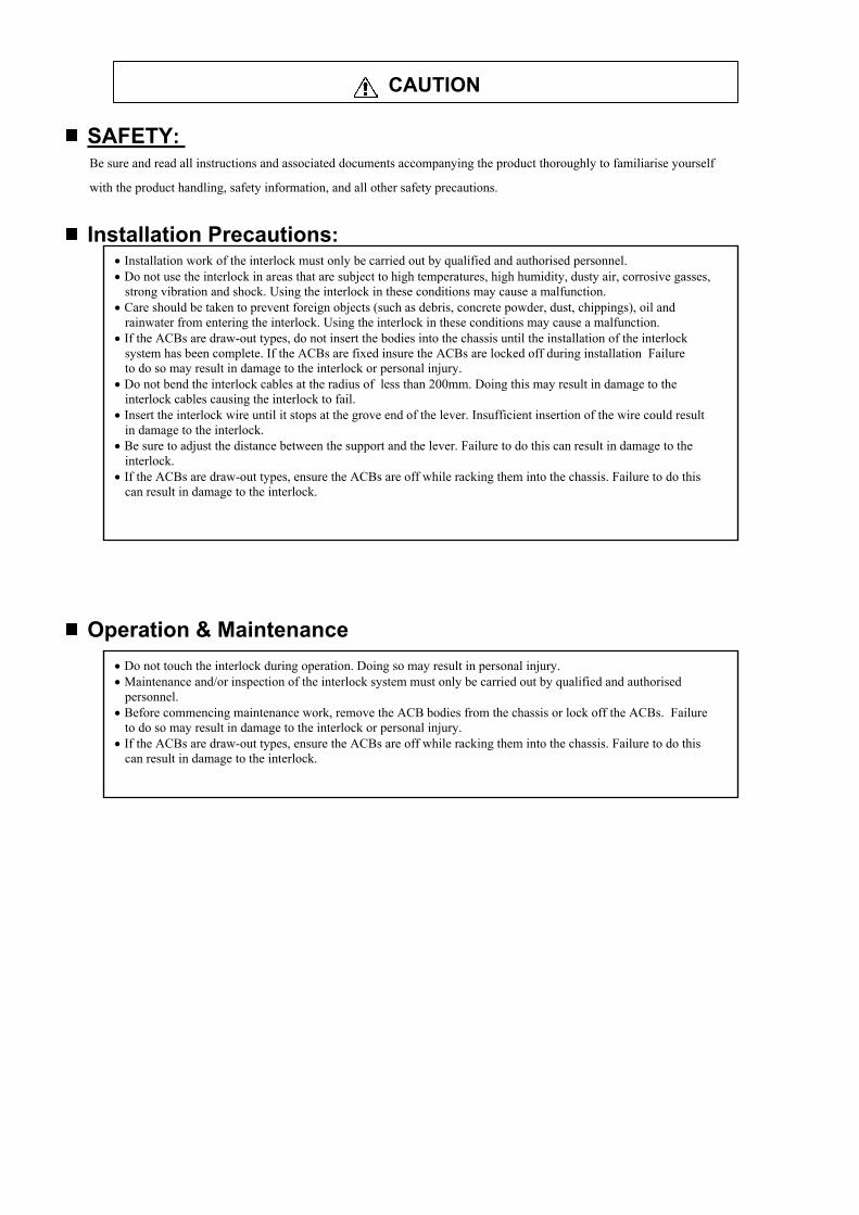
CAUTION
SAFETY: Be sure and read all instructions and associated documents accompanying the product thoroughly to familiarise yourself
with the product handling, safety information, and all other safety precautions.
Installation Precautions:
Op
• Installation work of the interlock must only be carried out by qualified and authorised personnel.• Do not use the interlock in areas that are subject to high temperatures, high humidity, dusty air, corrosive gasses, strong vibration and shock. Using the interlock in these conditions may cause a malfunction.• Care should be taken to prevent foreign objects (such as debris, concrete powder, dust, chippings), oil and rainwater from entering the interlock. Using the interlock in these conditions may cause a malfunction.• If the ACBs are draw-out types, do not insert the bodies into the chassis until the installation of the interlock system has been complete. If the ACBs are fixed insure the ACBs are locked off during installation Failure to do so may result in damage to the interlock or personal injury.• Do not bend the interlock cables at the radius of less than 200mm. Doing this may result in damage to the interlock cables causing the interlock to fail.• Insert the interlock wire until it stops at the grove end of the lever. Insufficient insertion of the wire could result in damage to the interlock.• Be sure to adjust the distance between the support and the lever. Failure to do this can result in damage to the interlock.• If the ACBs are draw-out types, ensure the ACBs are off while racking them into the chassis. Failure to do this can result in damage to the interlock.
eration & Maintenance• Do not touch the interlock during operation. Doing so may result in personal injury.• Maintenance and/or inspection of the interlock system must only be carried out by qualified and authorised personnel.• Before commencing maintenance work, remove the ACB bodies from the chassis or lock off the ACBs. Failure to do so may result in damage to the interlock or personal injury.• If the ACBs are draw-out types, ensure the ACBs are off while racking them into the chassis. Failure to do this can result in damage to the interlock.
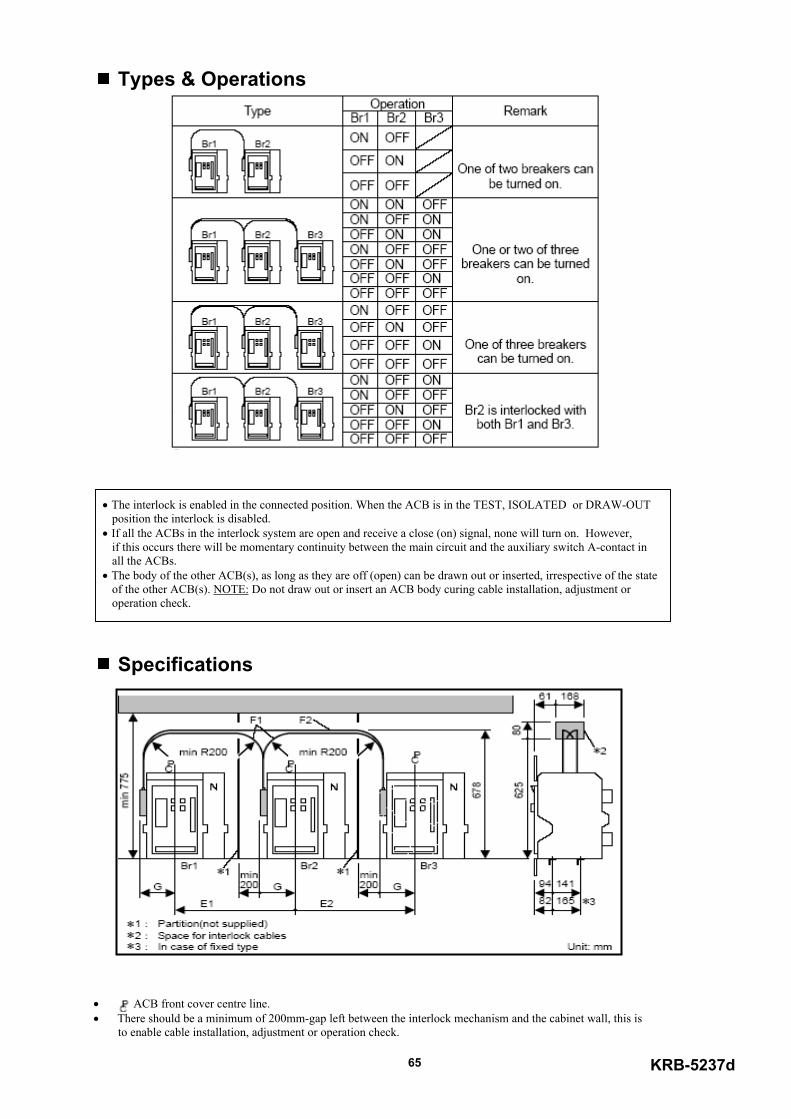
KRB-5237d65
Types & Operations
• The interlock is enabled in the connected position. When the ACB is in the TEST, ISOLATED or DRAW-OUT position the interlock is disabled. • If all the ACBs in the interlock system are open and receive a close (on) signal, none will turn on. However, if this occurs there will be momentary continuity between the main circuit and the auxiliary switch A-contact in all the ACBs. • The body of the other ACB(s), as long as they are off (open) can be drawn out or inserted, irrespective of the state of the other ACB(s). NOTE: Do not draw out or insert an ACB body curing cable installation, adjustment or operation check.
Specifications
• - ACB front cover centre line.• There should be a minimum of 200mm-gap left between the interlock mechanism and the cabinet wall, this is to enable cable installation, adjustment or operation check.
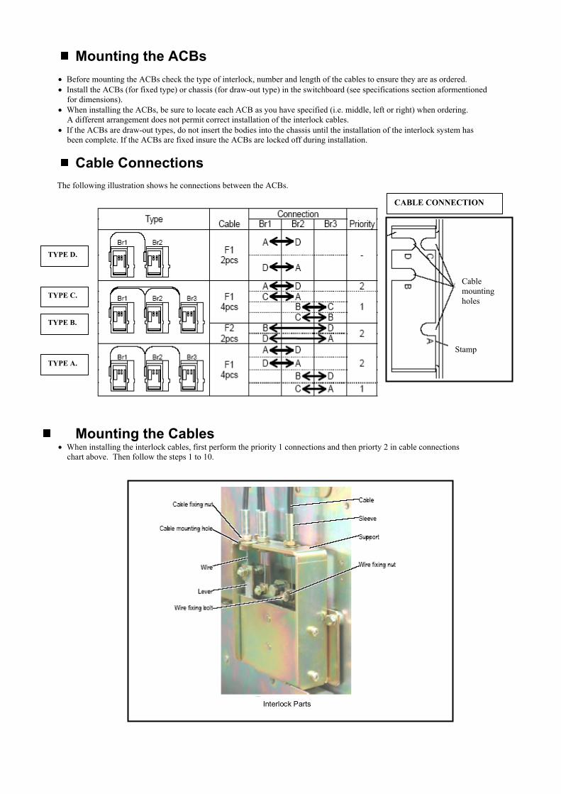
Mounting the ACBs• Before mounting the ACBs check the type of interlock, number and length of the cables to ensure they are as ordered.• Install the ACBs (for fixed type) or chassis (for draw-out type) in the switchboard (see specifications section aformentioned for dimensions).• When installing the ACBs, be sure to locate each ACB as you have specified (i.e. middle, left or right) when ordering. A different arrangement does not permit correct installation of the interlock cables.• If the ACBs are draw-out types, do not insert the bodies into the chassis until the installation of the interlock system has been complete. If the ACBs are fixed insure the ACBs are locked off during installation.
Cable Connections The following illustration shows he connections between the ACBs.
Mounting the Cables• When installing the interlock cables, first perform the priority 1 connections and then priorty 2 in cable connections chart above. Then follow the steps 1 to 10.
TYPE D.
TYPE A.
TYPE C.
TYPE B.
CABLE CONNECTION
Stamp
Cablemountingholes
INTERLOCK PARTS.
Interlock Parts

67
Cable
Sleeve
Cable fixing nut
Wire
1
Repeat steps 1 to 5 for the wire on theother end of the cable.
Temporarily tighten the cablefixing nut
Holding the wire, tighten theWire fixing nut to a torque of4.7 to 5.9 N.m.
Loosen the cable fixing nutand the wire fixing nut
Attach the cable in the cable mounting
6
3
54
7
If the distance is too small, turn the clockwise to lower the sleeve and thdistance until it falls within the specifiedtoo large, turn the cable-fixing nut clockand the lever, decreasing the distancespecified range.
If the ACBs are of a draw-out type, insethe chassis to the connected position. Dountil it is in the connected position. If thunlock the ACB.
After making sure the main circuit is notoperation of the ACB(s). Do not touchoperation
8
9
10
2
Push in and hold the wire untilIt stops against the groove endof the level
Hole and insert the wire into the wireInsertion hole of the wire fixing bolt
Make sure the distance between the support and the lever isas specfied and then tighten the cable fixing nut to a torqueof 12.5N.m. If the distance is out of the specfied range,proceed to step 8 to adjust the distance.
KRB-5237d
cable-fixing nut countere lever, increasing the
range. If the distance iswise to raise the sleeve until it falls within the
rt the ACB bodies into not turn the ACB(s) on
e ACB is a fixed typed,
energised, check the the interlock during
Inspection & Maintenance• If the ACBs are draw-out types, remove the ACB bodies from their chassis. If the ACBs are fixed ensure the ACBs are locked off.• Check the wire fixing nut and cable fixing nut for tightness. If loose, retighten to the specified torque.• Make sure the distance between the support and the lever is as specified. If the distance is out of the specified range, readjust it.• If the ACBs are of a draw-out type, insert the ACB bodies into the chassis to the connected position. Do not turn the ACB(s) on until it is in the connected position. If the ACB is a fixed type, unlock the ACB.• After making sure the main circuit is not energised, check the operation of the ACB(s). Do not touch the interlock during operation.
Published in June 2002.Revised in November 2002, April 2003, March 2004.The contents of this manual may be subject to change without notice.Recycle paper used.