Embed Size (px)
Citation preview
IEICE Electronics Express, Vol.17, No.11, 1–5
LETTER
Terahertz-wave generation from surface phonons at forbiddenfrequencies of lithium niobate
Jun-ichi Shikata1, a), Seigo Ohno2, 3, and Hiroaki Minamide3
Abstract This paper describes terahertz (THz)-wave generation withinforbidden bands in polar crystals, focusing on the A1 phonon modes inlithium niobate. This material exhibits two negative-permittivity frequencyranges at 7.4–12.7 THz and 18.8–25.6 THz for the lowest and highest A1modes, respectively. Exploiting the finite-difference time-domain simula-tions, we demonstrate that both the surface phonon modes can be radiativewith a structured grating. Fourier analyses of the radiative fields reveal therelevant peaks in the spectrum as well as the dispersion relations. Our re-sults provide a novel method for coherent THz-wave sources at unexploredTHz frequencies.Keywords: terahertz-wave generation, surface phonon, lithium niobate,negative permittivity, A1 modeClassification: Electromagnetic theory
1. Introduction
Recently, a variety of compact coherent terahertz (THz)-wave sources have been developed based on photonics andultrafast electronics. These sources include THz-wave gen-erators using nonlinear optics [1, 2, 3, 4, 5, 6, 7, 8, 9],photoconductive antennas [10, 11, 12], THz quantum cas-cade lasers [13, 14, 15], TUNNETT diodes [16, 17], uni-traveling-carrier photodiodes [18, 19, 20], resonant tunnel-ing diodes [21, 22, 23], and plasmonic THz emitters [24, 25].However, the interaction of optical phonons with photonsfrequently restricts the THz waves available, because it re-sults in forbidden bands [26], where the THz waves areunable to propagate over a long distance in bulk media. InTHz-wave generation by stimulated polariton scattering inLiNbO3 (LN) [1, 2, 3, 4, 5, 6], the tuning range is limitedto 0.7–3.0 THz due to the substantial absorption loss of theTHz waves interacting with the lowest A1 phonon mode (7.4THz).
A possible way to generate THz waves at forbiddenfrequencies in bulk is to couple out the excited surfacephonons [27]. In fact, thermally excited surface phononson SiC gratings have been shown to exhibit infrared emis-sion [28], and the spectra of this emission cover a wide
1 College of Engineering, Nihon University, Koriyama 963-8642, Japan
2 Graduate School of Science, Tohoku University, Aoba-ku,Sendai 980-8578, Japan
3 RIKEN Center for Advanced Photonics (RAP), RIKEN, Aoba-ku, Sendai 980-0845, Japan
DOI: 10.1587/elex.17.20200133Received April 6, 2020Accepted April 16, 2020Publicized April 30, 2020Copyedited June 10, 2020
frequency range (more than several THz) in the forbiddenband. Since surface waves have long-range coherence [29],coherent emissions occur even with incoherent excitations.
In this paper, we explore THz-wave generation from sur-face phonons, focusing on the A1 modes in LN crystals. Wediscover surface phonon modes arising from the lowest andhighest A1 modes. Finite-difference time-domain simula-tions reveal the THz-wave radiation from a grating surface.The emission spectra as well as the dispersion relations arefound using Fourier analyses.
2. Theoretical background
In the bulk of a polar crystal, the interaction between trans-verse optical (TO) phonons and transverse photons resultsin coupled modes, called polaritons [26]. With respectto a simple single-oscillator (two-atom) model in losslessmedia, the polariton wavevector (i.e., dispersion relation)k(ω) = (ω/c)
√ε(ω) is determined using the following di-
electric function:
ε(ω) = ε∞ +Sω2
T
ω2T − ω2
=ε∞(ω2
L − ω2)ω2T − ω2
(1)
where ε∞ is the permittivity for high frequencies, S is theoscillator strength, ωT is the frequency of the TO phonon,and ωL is the frequency of the longitudinal optical phonon.As ε(ω) < 0 at ωT < ω < ωL , the wavevector is purelyimaginary (k = i |k |); thus, the amplitude of the electromag-netic wave decays as exp(−|k |x) according to its distancefrom the surface (forbidden band). The zero point of Eq. (1)[ε(0) = ε0] provides the well-known Lyddane–Sachs–Teller(LST) relation as follows:
ωL
ωT=
√ε0ε∞
(2)
Although the electromagnetic waves at the forbidden fre-quencies cannot propagate for long in bulk, surface waves(known as surface phonons [27]) can freely propagate alongthe surface with transverse magnetic (TM) polarization. Ona flat surface between the crystal and air, the electromagneticboundary conditions yield the following surface phononwavevector:
kSP(ω) =ω
c
√ε(ω)ε(ω) + 1
(3)
The dispersion curve of the surface phonon emerges fromωT [ε(ω) = −∞], whereas the upper limit ωs is specified by
Copyright © 2020 The Institute of Electronics, Information and Communication Engineers1

IEICE Electronics Express, Vol.17, No.11, 1–5
ωs = ωT
√ε0 + 1ε∞ + 1
(4)
from the condition kSP = ∞ [ε(ω) = −1] in Eq. (3).It is worth noting that the dispersion curve is below the
light line k = ω/c because ε(ω)/(ε(ω)+1) > 1 in Eq. (3) at−∞ < ε(ω) < −1. Since the energy and momentum conser-vations do not hold simultaneously, THz-wave emissions donot occur from surface phonons on a flat surface. However,if a Bragg grating (Fig. 1) is structured on the surface, theradiative coupling becomes possible in accordance with thecondition of momentum conservation:
kSP(ω) =ω
csin θ + m
2πΛ
(5)
where θ is the radiation angle, m is the diffraction order (aninteger), and Λ is the grating period.
Fig. 1 Schematic diagram of THz-wave generation from surface phononson a grating surface of LN.
3. Dispersion relations of A1 modes in LN
3.1 Bulk polariton modesSince an LN crystal has four A1 modes, the nth mode canbe designated as A1
(n) in Table I. We used the multi-oscillator model of the dielectric function, including thenon-negligible damping terms, described as
ε(ω) = ε∞ +∑n
Snω2Tn
ω2Tn
− ω2 − i Γnω(6)
where Γn is the damping coefficient.
Table I Optical parameters of A1 modes in LN [30].
Fig. 2 shows the dielectric properties calculated fromEq. (6). The strong resonances (A1
(1), A1(4)) almost deter-
mine the dispersive and loss characteristics of the polaritonsin Figs. 2(a) and 2(b), whereas the weak resonances (A1
(2),A1
(3)) contribute less. The resulting negative-permittivityregions emerge at 7.4–12.7 THz and 18.8–25.6 THz [theupper part of Fig. 2(a)]. Accordingly, we focused on thelowest and highest A1 modes to study the surface phononbands and their emissions, as shown below.
3.2 Surface phonon modes on a flat surfaceTo solve Eq. (3) for the lossy case [Eq. (6)], we employedthe complex frequency scheme [31], where the frequency
Fig. 2 Dielectric properties associated with A1 modes in bulk LN. (a)Complex dielectric functions. (b) Dispersion relations of the polaritons.The frequency is assumed to be real. The dashed lines denote the TOphonon frequencies (ωT ). The absorption coefficient is defined by α = 2Im k.
was assumed to be complex (ω = ω′ − iω′′, such that theamplitude decay was expressed as exp(−ω′′t). We modifiedEq. (3) to the following system of nonlinear equations:
kSP = Re
[ω′ − iω′′
c
√ε(ω′ − iω′′)ε(ω′ − iω′′) + 1
](7)
0 = Im
[ω′ − iω′′
c
√ε(ω′ − iω′′)ε(ω′ − iω′′) + 1
](8)
Eq. (7) as well as Eqs. (6) and (8) were numerically solvedfor each fixed real wavevector kSP .
Fig. 3 illustrates the resulting dispersion relations of theA1 surface phonon modes. In Fig. 3(a), the lower branchemerges from ωT = 7.4 THz, asymptotically approachingthe upper limit ωs = 14.6 THz. Moreover, in Fig. 3(b), thelower branch extends from ωT = 18.8 THz to ωs = 22.7THz. Both the upper limits (ωs) agree well with thoseresulting from Eq. (4). In this way, we found that boththe lower branches in Figs. 3(a) and 3(b) were of surfacephonons that were relevant to the A1
(1) and A1(4) modes,
respectively.
Fig. 3 Dispersion relations of surface phonon modes on a flat surface.(a) A1
(1) mode, ωs = 14.6 THz. (b) A1(4) mode, ωs = 22.7 THz. The
surface wavevector kSP is assumed to be real.
Note that the A1(4) surface phonon band (18.8–22.7 THz)
is within the negative-permittivity region (18.8–25.6 THz)[Fig. 2(a)]; however, ωs = 14.6 THz of the A1
(1) modeexceeds the upper boundary of the forbidden band (12.7THz). This anomaly results from the large oscillator strengthS (i.e., ε0) of the A1
(1) mode, which results in the breakdownof the LST relation [32]. Indeed, for the A1
(1) mode, theLST relation (2) is broken (ωL/ωT = 1.1,
√ε0/ε∞ = 2.1),
whereas the relation holds well for the A1(4) mode (ωL/ωT =
1.4,√ε0/ε∞ = 1.2).
2
IEICE Electronics Express, Vol.17, No.11, 1–5
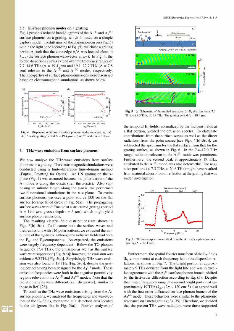
3.3 Surface phonon modes on a gratingFig. 4 presents reduced band diagrams of the A1
(1) and A1(4)
surface phonons on a grating, which is based on a simplegapless model. To shift most of the dispersion curves (Fig. 3)within the light cone according to Eq. (5), we chose a gratingperiod Λ such that the zone edge π/Λ was located close tokmin (the surface phonon wavevector at ωT ). In Fig. 4, thefolded dispersion curves extend over the frequency ranges of7.7–14.6 THz (Λ = 19.4 µm) and 19.1–22.7 THz (Λ = 7.8µm) relevant to the A1
(1) and A1(4) modes, respectively.
Their properties of surface phonon emissions were discussedbased on electromagnetic simulations, as shown below.
Fig. 4 Dispersion relations of surface phonon modes on a grating. (a)A1
(1) mode, grating period Λ = 19.4 µm. (b) A1(4) mode, Λ = 7.8 µm.
4. THz-wave emissions from surface phonons
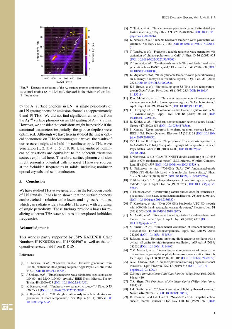
We now analyze the THz-wave emissions from surfacephonons on a grating. The electromagnetic simulations wereconducted using a finite-difference time-domain method(Fujitsu, Poynting for Optics). An LN grating on the x-plane (Fig. 1) was assumed because the polarization of theA1 mode is along the c-axis (i.e., the z-axis). Also sup-posing an infinite length along the y-axis, we performedtwo-dimensional simulations in the x–z plane. To excitesurface phonons, we used a point source [33] on the flatsurface [orange filled circle in Fig. 5(a)]. The propagatingsurface waves were diffracted at a structured grating (periodΛ = 19.4 µm, groove depth t = 3 µm), which might yieldsurface phonon emissions.
The resulting electric field distributions are shown inFigs. 5(b)–5(d). To illustrate both the surface waves andtheir emissions with TM polarizations, we extracted the am-plitude of the Ez-fields, although the radiative fields had boththe Ex- and Ez-components. As expected, the emissionswere largely frequency dependent. Below the TO phononfrequency (7.4 THz), the emission as well as the surfacewave were suppressed [Fig. 5(b)]; however, the emission wasevident at 9.5 THz [Fig. 5(c)]. Surprisingly, THz-wave emis-sion was also found at 19 THz [Fig. 5(d)], despite the grat-ing period having been designed for the A1
(1) mode. Theseemission frequencies were both in the negative-permittivityregions relevant to the A1
(1) and A1(4) modes. Note that the
radiation angles were different (i.e., dispersive), similar tothose in Ref. [28].
To confirm the THz-wave emissions arising from the A1surface phonons, we analyzed the frequencies and wavevec-tors of the Ez-fields, monitored at a detection area locatedin the air [green line in Fig. 5(a)]. Fourier analyses of
Fig. 5 (a) Schematic of the studied structure. (b) Ez distribution at 7.0THz, (c) 9.5 THz, (d) 19 THz. The grating period Λ = 19.4 µm.
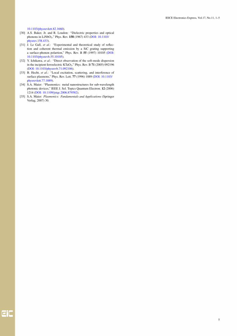
the temporal Ez-fields, normalized by the incident fields ata flat portion, yielded the emission spectra. To eliminatecontributions from the surface waves as well as the directradiations from the point source [see Figs. 5(b)–5(d)], wesubtracted the spectrum for the flat surface from that for thegrating surface, as shown in Fig. 6. In the 7.4–12.0 THzrange, radiation relevant to the A1
(1) mode was prominent.Furthermore, the second peak at approximately 19 THz,attributed to the A1
(4) mode, was also noteworthy. The neg-ative portions (< 7.3 THz, > 20.6 THz) might have resultedfrom material absorption or reflection at the grating that wasunder investigation.
Fig. 6 THz-wave spectrum emitted from the A1 surface phonons on agrating (Λ = 19.4 µm).
Furthermore, the spatial Fourier transform of the Ez-fields(kz-components) at each frequency led to the dispersion re-lations, as shown in Fig. 7. The bright portion at approxi-mately 9 THz deviated from the light line and was in excel-lent agreement with the A1
(1) surface phonon branch, shiftedby the first-order diffraction according to Eq. (5). Despitethe limited frequency range, the second bright portion at ap-proximately 19 THz (kSP/2π ∼ 120 cm−1) also agreed wellwith the first-order diffracted surface phonon branch of theA1
(4) mode. These behaviors were similar to the plasmonicresonance on a metal grating [34, 35]. Therefore, we decidedthat the present THz-wave radiations were those supported
3
IEICE Electronics Express, Vol.17, No.11, 1–5
Fig. 7 Dispersion relations of the A1 surface-phonon emissions from astructured grating (Λ = 19.4 µm), depicted in the vicinity of the firstBrillouin zone.
by the A1 surface phonons in LN. A single periodicity ofan LN grating opens the emission channels at approximately9 and 19 THz. We did not find significant emissions fromthe A1
(4) surface phonons on an LN grating of Λ = 7.8 µm.However, we consider that emissions might be possible if thestructural parameters (especially, the groove depths) wereoptimized. Although we have herein studied the linear opti-cal phenomena on THz electromagnetic waves, the results ofour research might also hold for nonlinear-optic THz-wavegeneration [1, 2, 3, 4, 5, 6, 7, 8, 9]. Laser-induced nonlin-ear polarizations are equivalent to the coherent excitationsources exploited here. Therefore, surface phonon emissionmight present a potential path to novel THz-wave sourcesat the forbidden frequencies in solids, including nonlinearoptical crystals and semiconductors.
5. Conclusion
We have studied THz-wave generation in the forbidden bandsof LN crystals. It has been shown that the surface phononscan be excited in relation to the lowest and highest A1 modes,which can radiate widely tunable THz waves with a gratingof single periodicity. These findings provide a basis for re-alizing coherent THz-wave sources at unexplored forbiddenfrequencies.
Acknowledgments
This work is partly supported by JSPS KAKENHI GrantNumbers JP19K05286 and JP18K04967 as well as the co-operative research aid from RIKEN.
References
[1] K. Kawase, et al.: “Coherent tunable THz-wave generation fromLiNbO3 with monolithic grating coupler,” Appl. Phys. Lett. 68 (1996)2483 (DOI: 10.1063/1.115828).
[2] J. Shikata, et al.: “Tunable terahertz-wave parametric oscillators usingLiNbO3 and MgO: LiNbO3 crystals,” IEEE Trans. Microw. TheoryTechn. 48 (2000) 653 (DOI: 10.1109/22.841956).
[3] K. Kawase, et al.: “Terahertz wave parametric source,” J. Phys. D 35(2002) R1 (DOI: 10.1088/0022-3727/35/3/201).
[4] S. Hayashi, et al.: “Ultrabright continuously tunable terahertz-wavegeneration at room temperature,” Sci. Rep. 4 (2014) 5045 (DOI:10.1038/srep05045).
[5] Y. Takida, et al.: “Terahertz-wave parametric gain of stimulated po-lariton scattering,” Phys. Rev. A 93 (2016) 043836 (DOI: 10.1103/physreva.93.043836).
[6] K. Nawata, et al.: “Tunable backward terahertz-wave parametric os-cillation,” Sci. Rep. 9 (2019) 726 (DOI: 10.1038/s41598-018-37068-7).
[7] T. Tanabe, et al.: “Frequency-tunable terahertz wave generation viaexcitation of phonon-polaritons in GaP,” J. Phys. D 36 (2003) 953(DOI: 10.1088/0022-3727/36/8/302).
[8] T. Taniuchi, et al.: “Continuously tunable THz and far-infrared wavegeneration from DAST crystal,” Electron. Lett. 40 (2004) 60 (DOI:10.1049/el:20040380).
[9] K. Miyamoto, et al.: “Widely tunable terahertz-wave generation usingan N-benzyl-2-methyl-4-nitroaniline crystal,” Opt. Lett. 33 (2008)252 (DOI: 10.1364/ol.33.000252).
[10] E.B. Brown, et al.: “Photomixing up to 3.8 THz in low temperature-grown GaAs,” Appl. Phys. Lett. 66 (1995) 285 (DOI: 10.1063/1.113519).
[11] K.A. McIntosh, et al.: “Terahertz measurements of resonant pla-nar antennas coupled to low-temperature-grown GaAs photomixers,”Appl. Phys. Lett. 69 (1996) 3632 (DOI: 10.1063/1.117006).
[12] I.S. Gregory, et al.: “Continuous-wave terahertz system with a 60dB dynamic range,” Appl. Phys. Lett. 86 (2005) 204104 (DOI:10.1063/1.1935032).
[13] R. Köhler, et al.: “Terahertz semiconductor-heterostructure Laser,”Nature 417 (2002) 156 (DOI: 10.1038/417156a).
[14] S. Kumar: “Recent progress in terahertz quantum cascade Lasers,”IEEE J. Sel. Topics Quantum Electron. 17 (2011) 38 (DOI: 10.1109/jstqe.2010.2049735).
[15] T.-T. Lin and H. Hirayama: “Improvement of operation temperature inGaAs/AlGaAs THz-QCLs by utilizing high Al composition barrier,”Phys. Status Solidi C 10 (2013) 1430 (DOI: 10.1002/pssc.201300216).
[16] J. Nishizawa, et al.: “GaAs TUNNETT diodes oscillating at 430-655GHz in CW fundamental mode,” IEEE Microw. Wireless Compon.Lett. 15 (2005) 597 (DOI: 10.1109/lmwc.2005.855381).
[17] J. Nishizawa, et al.: “706-GHz GaAs CW fundamental-modeTUNNETT diodes fabricated with molecular layer epitaxy,” Phys.Status Solidi C 5 (2008) 2802 (DOI: 10.1002/pssc.200779256).
[18] T. Ishibashi, et al.: “High-speed response of uni-traveling-carrier pho-todiodes,” Jpn. J. Appl. Phys. 36 (1997) 6263 (DOI: 10.1143/jjap.36.6263).
[19] T. Ishibashi, et al.: “Unitraveling-carrier photodiodes for terahertz ap-plications,” IEEE J. Sel. Topics Quantum Electron. 20 (2014) 3804210(DOI: 10.1109/jstqe.2014.2336537).
[20] T. Kurokawa, et al.: “Over 300 GHz bandwidth UTC-PD modulewith 600 GHz band rectangular waveguide output,” Electron. Lett. 54(2018) 705 (DOI: 10.1049/el.2018.0932).
[21] M. Asada, et al.: “Resonant tunneling diodes for sub-terahertz andterahertz oscillators,” Jpn. J. Appl. Phys. 47 (2008) 4375 (DOI:10.1143/jjap.47.4375).
[22] S. Suzuki, et al.: “Fundamental oscillation of resonant tunnelingdiodes above 1 THz at room temperature,” Appl. Phys. Lett. 97 (2010)242102 (DOI: 10.1063/1.3525834).
[23] R. Izumi, et al.: “Resonant-tunneling-diode terahertz oscillator with acylindrical cavity for high-frequency oscillation,” AIP Adv. 9 (2019)085020 (DOI: 10.1063/1.5114963).
[24] Y.M. Meziani, et al.: “Room temperature generation of terahertz ra-diation from a grating-bicoupled plasmon-resonant emitter: Size ef-fect,” Appl. Phys. Lett. 90 (2007) 061105 (DOI: 10.1063/1.2459879).
[25] A.A. Dubinov, et al.: “Terahertz plasmon-emitting graphene-channeltransistor,” Opto-Electron. Rev. 27 (2019) 345 (DOI: 10.1016/j.opelre.2019.11.003).
[26] C. Kittel: Introduction to Solid State Physics (Wiley, New York, 2005)8th ed. 410.
[27] Y.R. Shen: The Principles of Nonlinear Optics (Wiley, New York,1984) 481.
[28] J.-J. Greffet, et al.: “Coherent emission of light by thermal sources,”Nature 416 (2002) 61 (DOI: 10.1038/416061a).
[29] R. Carminati and J.-J. Greffet: “Near-field effects in spatial coher-ence of thermal sources,” Phys. Rev. Lett. 82 (1999) 1660 (DOI:
4
IEICE Electronics Express, Vol.17, No.11, 1–5
10.1103/physrevlett.82.1660).[30] A.S. Baker, Jr. and R. Loudon: “Dielectric properties and optical
phonons in LiNbO3,” Phys. Rev. 158 (1967) 433 (DOI: 10.1103/physrev.158.433).
[31] J. Le Gall, et al.: “Experimental and theoretical study of reflec-tion and coherent thermal emission by a SiC grating supportinga surface-phonon polartion,” Phys. Rev. B 55 (1997) 10105 (DOI:10.1103/physrevb.55.10105).
[32] Y. Ichikawa, et al.: “Direct observation of the soft-mode dispersionin the incipient ferroelectric KTaO3,” Phys. Rev. B 71 (2005) 092196(DOI: 10.1103/physrevb.71.092106).
[33] B. Hecht, et al.: “Local excitation, scattering, and interference ofsurface plasmons,” Phys. Rev. Lett. 77 (1996) 1889 (DOI: 10.1103/physrevlett.77.1889).
[34] S.A. Maier: “Plasmonics: metal nanostructures for sub-wavelengthphotonic devices,” IEEE J. Sel. Topics Quantum Electron. 12 (2006)1214 (DOI: 10.1109/jstqe.2006.879582).
[35] S.A. Maier: Plasmonics: Fundamentals and Applications (SpringerVerlag, 2007) 30.
5

![Review of Terahertz Tomography Techniques - Inria · PDF fileReview of Terahertz Tomography Techniques ... Gunn diode [73], plasma wave transistor [74, 75], Backward Wave Oscillator](https://img.pdfslide.us/doc/110x75/5ab01d3a7f8b9a3a038e439b/review-of-terahertz-tomography-techniques-inria-of-terahertz-tomography-techniques.jpg)


![Efficient Optical to Terahertz Wave Conversion through ... · [7] M. Jarrahi, "Advanced Photoconductive Terahertz Optoelectronics based on Nano- Antennas and NanoPlasmonic Light Concentrators",](https://img.pdfslide.us/doc/110x75/5f056df67e708231d412ec02/efficient-optical-to-terahertz-wave-conversion-through-7-m-jarrahi-advanced.jpg)