Embed Size (px)
Citation preview

FILE NO. A04-016
TCS-NET AIR CONDITIONINGCONTROL SYSTEM(TOUCH SCREEN CONTROLLER)
TENTATIVE
2
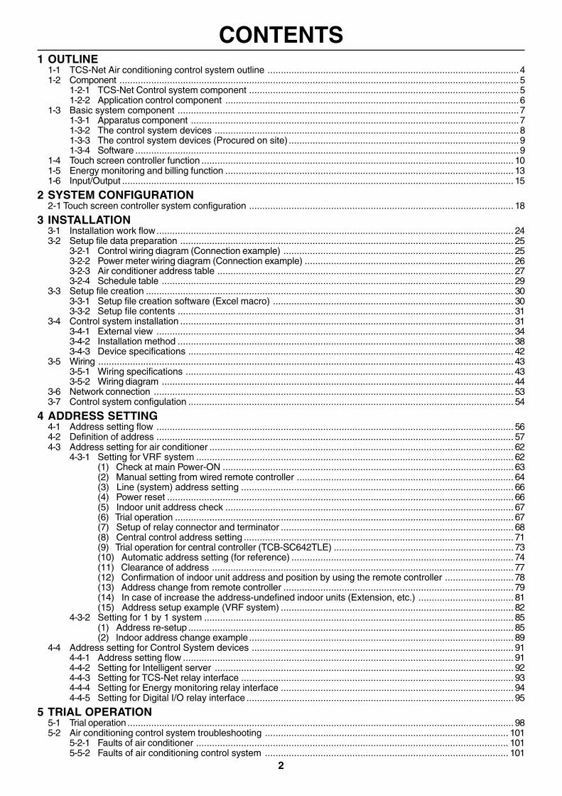
CONTENTS1 OUTLINE
1-1 TCS-Net Air conditioning control system outline ...............................................................................................41-2 Component .......................................................................................................................................................5
1-2-1 TCS-Net Control system component ......................................................................................................51-2-2 Application control component ...............................................................................................................6
1-3 Basic system component .................................................................................................................................71-3-1 Apparatus component ............................................................................................................................71-3-2 The control system devices ...................................................................................................................81-3-3 The control system devices (Procured on site) .......................................................................................91-3-4 Software .................................................................................................................................................9
1-4 Touch screen controller function ...................................................................................................................... 101-5 Energy monitoring and billing function ............................................................................................................. 131-6 Input/Output .................................................................................................................................................... 15
2 SYSTEM CONFIGURATION2-1 Touch screen controller system configuration .................................................................................................... 18
3 INSTALLATION3-1 Installation work flow....................................................................................................................................... 243-2 Setup file data preparation .............................................................................................................................. 25
3-2-1 Control wiring diagram (Connection example) ....................................................................................... 253-2-2 Power meter wiring diagram (Connection example) ............................................................................... 263-2-3 Air conditioner address table ................................................................................................................ 273-2-4 Schedule table ..................................................................................................................................... 29
3-3 Setup file creation ........................................................................................................................................... 303-3-1 Setup file creation software (Excel macro) ........................................................................................... 303-3-2 Setup file contents ............................................................................................................................... 31
3-4 Control system installation .............................................................................................................................. 313-4-1 External view ....................................................................................................................................... 343-4-2 Installation method ............................................................................................................................... 383-4-3 Device specifications ........................................................................................................................... 42
3-5 Wiring ............................................................................................................................................................. 433-5-1 Wiring specifications ............................................................................................................................ 433-5-2 Wiring diagram ..................................................................................................................................... 44
3-6 Network connection ........................................................................................................................................ 533-7 Control system configulation ........................................................................................................................... 54
4 ADDRESS SETTING4-1 Address setting flow ....................................................................................................................................... 564-2 Definition of address ....................................................................................................................................... 574-3 Address setting for air conditioner ................................................................................................................... 62
4-3-1 Setting for VRF system ........................................................................................................................ 62(1) Check at main Power-ON .............................................................................................................. 63(2) Manual setting from wired remote controller .................................................................................. 64(3) Line (system) address setting ....................................................................................................... 66(4) Power reset ................................................................................................................................... 66(5) Indoor unit address check ............................................................................................................. 67(6) Trial operation ................................................................................................................................ 67(7) Setup of relay connector and terminator ........................................................................................ 68(8) Central control address setting ...................................................................................................... 71(9) Trial operation for central controller (TCB-SC642TLE) .................................................................... 73(10) Automatic address setting (for reference) .................................................................................... 74(11) Clearance of address .................................................................................................................. 77(12) Confirmation of indoor unit address and position by using the remote controller .......................... 78(13) Address change from remote controller ....................................................................................... 79(14) In case of increase the address-undefined indoor units (Extension, etc.) .................................... 81(15) Address setup example (VRF system) ........................................................................................ 82
4-3-2 Setting for 1 by 1 system ..................................................................................................................... 85(1) Address re-setup ........................................................................................................................... 85(2) Indoor address change example .................................................................................................... 89
4-4 Address setting for Control System devices ................................................................................................... 914-4-1 Address setting flow ............................................................................................................................. 914-4-2 Setting for Intelligent server ................................................................................................................. 924-4-3 Setting for TCS-Net relay interface ....................................................................................................... 934-4-4 Setting for Energy monitoring relay interface ........................................................................................ 944-4-5 Setting for Digital I/O relay interface ..................................................................................................... 95
5 TRIAL OPERATION5-1 Trial operation .................................................................................................................................................. 985-2 Air conditioning control system troubleshooting ............................................................................................ 101
5-2-1 Faults of air conditioner ...................................................................................................................... 1015-5-2 Faults of air conditioning control system ............................................................................................ 101
3
1
OUTLINE
1-1 TCS-Net Air conditioning control system outline1-2 Component
1-2-1 TCS-Net control system component1-2-2 Application control component
1-3 Basic system component1-3-1 Apparatus component1-3-2 The control system devices1-3-3 The control system devices (Procured on site)1-3-4 Software
1-4 Touch screen controller function1-5 Energy monitoring and billing function1-6 Input/Output
4
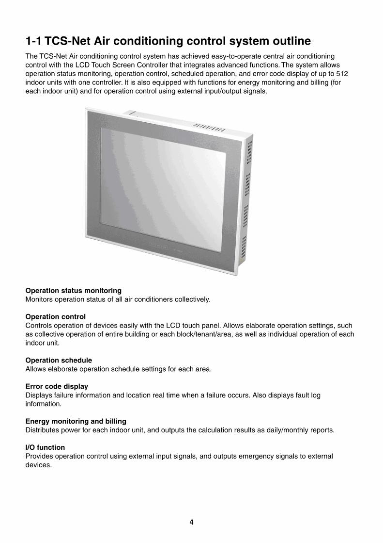
1-1 TCS-Net Air conditioning control system outlineThe TCS-Net Air conditioning control system has achieved easy-to-operate central air conditioningcontrol with the LCD Touch Screen Controller that integrates advanced functions. The system allowsoperation status monitoring, operation control, scheduled operation, and error code display of up to 512indoor units with one controller. It is also equipped with functions for energy monitoring and billing (foreach indoor unit) and for operation control using external input/output signals.
Operation status monitoringMonitors operation status of all air conditioners collectively.
Operation controlControls operation of devices easily with the LCD touch panel. Allows elaborate operation settings, suchas collective operation of entire building or each block/tenant/area, as well as individual operation of eachindoor unit.
Operation scheduleAllows elaborate operation schedule settings for each area.
Error code displayDisplays failure information and location real time when a failure occurs. Also displays fault loginformation.
Energy monitoring and billingDistributes power for each indoor unit, and outputs the calculation results as daily/monthly reports.
I/O functionProvides operation control using external input signals, and outputs emergency signals to externaldevices.
5
SM
MS
SH
RM
Sid
e re
mot
e co
ntro
ller
Mas
ter
rem
ote
cont
rolle
r
TC
S-N
et In
terf
ace BM
S-I
FLS
V1E
BM
S-T
P06
40A
CE
BM
S-T
P06
40P
WE
BM
S-T
P51
20A
CE
BM
S-T
P51
20P
WE
Touc
h sc
reen
co
ntro
ller
Pow
er m
eter
BM
S-I
FW
H3E
Ene
rgy
met
er
rela
y in
terf
ace
Dig
ita l/
O R
elay
In
terf
ace
BM
S-I
FD
D01
E
PC
for
Ene
rgy
mon
itorin
gan
d bi
lling
Sup
er D
igita
l Inv
erte
rD
igita
l Inv
erte
r
"1:1
mod
el"
conn
ectio
n in
terf
ace
TC
B-P
CN
T30
TLE
I/F I/F
HU
B
PC
BM
S-L
SV
2E
Inte
llige
ntse
rver
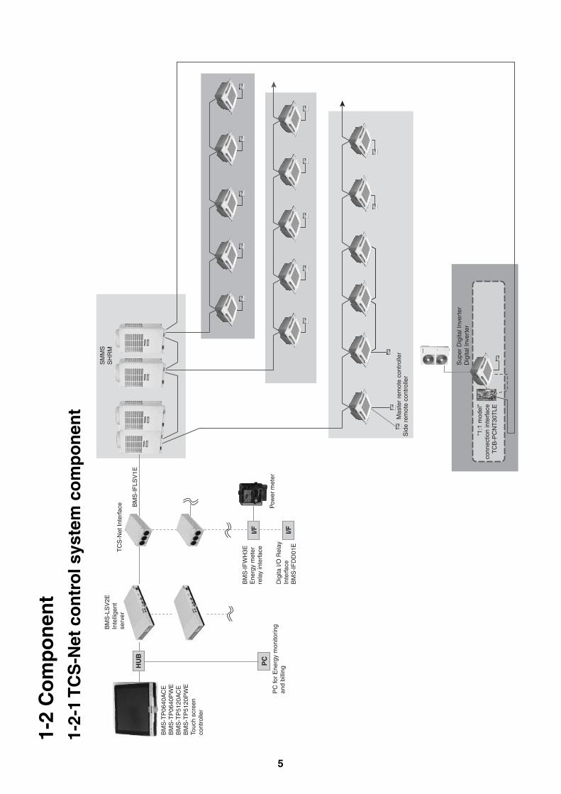
1-2
Co
mp
on
ent
1-2-
1 T
CS
-Net
co
ntr
ol s
yste
m c
om
po
nen
t
6
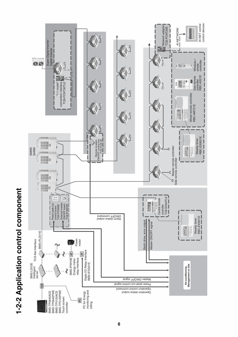
1-2-
2 A
pp
licat
ion
co
ntr
ol c
om
po
nen
tS
MM
SS
HR
M
Alarm status outputON/OFF command
Air
-co
nd
itio
nin
g
Man
agem
ent
on
sit
e
I/F I/FP
C
HUB
Term
inal
Scr
ew M
3 6
55.5
45.5
60
50
PJ17
TO
SH
IBA
NC
C-1
21
4T
CB
-PC
MO
1
TC
B-P
CM
O1
E
4-4ø
hol
e
5
4 1
ICI
41
D2
HEAT
COM
COM COOL
10
TB
1
8
Term
inal
Scr
ew M
3 6
71 61
Term
inal
Scr
ew M
4 8
4-4ø
hol
e
85
75
OFF
OFF ON
MS
10
MS
OFF
COM COMON
ONT82
T81
K100
PJ17
5
5ICI
41
8
OPERATION/
TO
SH
IBA
NC
C-1
21
2
TC
B-P
CO
M1
TC
B-P
CO
M1
E
Bat
ch d
rive,
err
or o
utpu
t
Mas
ter
ON
/OF
F s
igna
l
Power peak-cut control signal
Operation status outputOperation control command
Wire
d re
mot
e co
ntro
ller
RB
C-A
MT
21E
Sid
e re
mot
e co
ntro
ller
Mas
ter
rem
ote
cont
rolle
r
Wee
kly
timer
RB
C-E
XW
21E
Wee
kly
timer
RB
C-E
XW
21E
Sub
-rem
ote
cont
rolle
rR
BC
-AS
21E
Wire
less
rem
ote
cont
rolle
r
Cen
tral r
emot
e co
ntro
ller
TCB
-SC
642T
LE
Ext
erna
l mas
ter
ON
/OF
F b
oard
TC
B-P
CM
O2E
Pow
er p
eak-
cut
cont
rol b
oard
TC
B-P
CD
M2E
TC
S-N
et In
terf
ace
BM
S-L
SV
2EIn
telli
gent
serv
erB
MS
-IF
LSV
1E
BM
S-T
P06
40A
CE
BM
S-T
P06
40P
WE
BM
S-T
P51
20A
CE
BM
S-T
P51
20P
WE
Touc
h sc
reen
co
ntro
ller
Pow
er
met
er
BM
S-I
FW
H3E
Ene
rgy
met
er
rela
y in
terf
ace
Dig
ita l/
O R
elay
Inte
rfac
e B
MS
-IF
DD
01E
PC
for
Ene
rgy
mon
itorin
g an
d bi
lling
Sup
er D
igita
l Inv
erte
rD
igita
l Inv
erte
r
"1:1
mod
el"
conn
ectio
n in
terf
ace
TC
B-P
CN
T30
TLE
Net
wor
k ad
apte
rT
CB
-PC
NT
20E
AI-
NE
TW
OR
K
AI-
NE
T c
entr
al
cont
rol d
evic
es
Rem
ote
loca
tion
ON
/OF
F c
ontr
ol b
oxT
CB
-IF
CB
-4E
Master ON/OFF signal
7
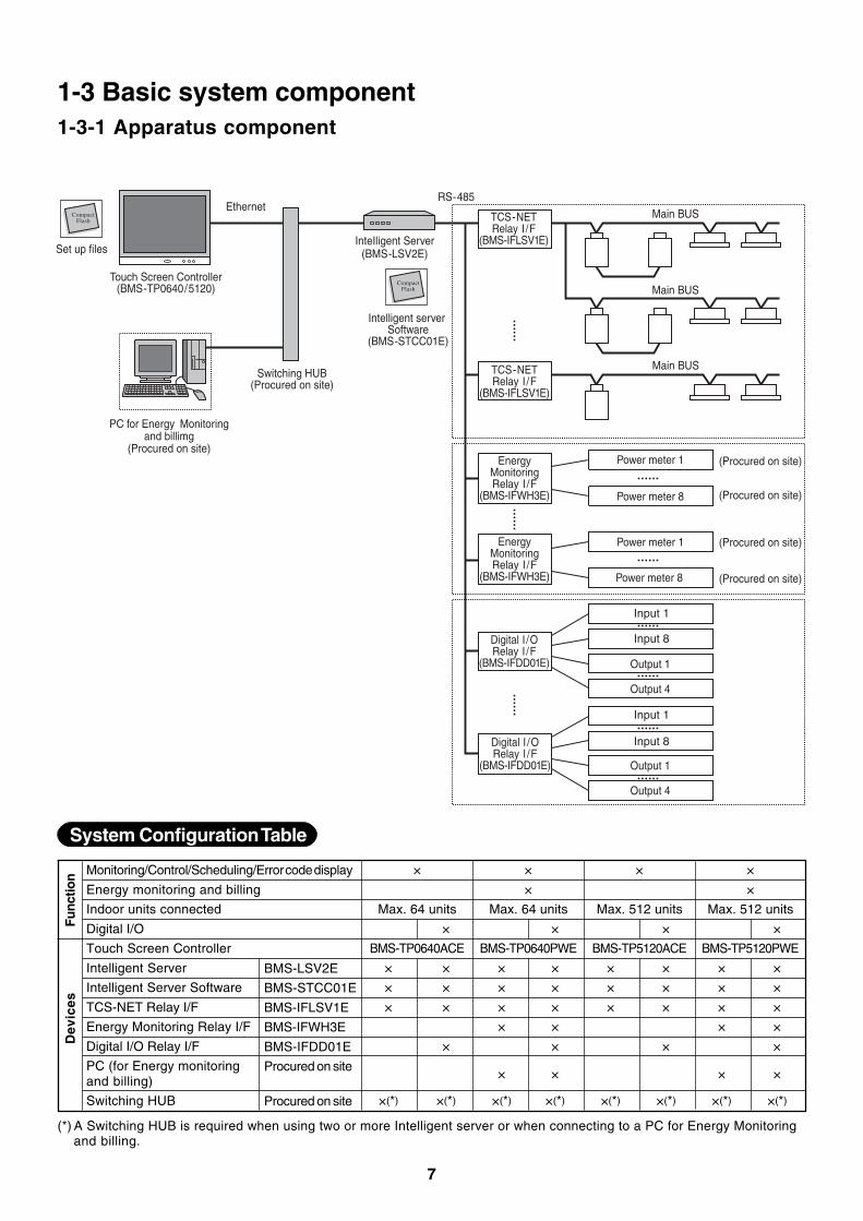
System Configuration Table
Monitoring/Control/Scheduling/Error code display
Energy monitoring and billing
Indoor units connected
Digital I/O
Touch Screen Controller
Intelligent Server
Intelligent Server Software
TCS-NET Relay I/F
Energy Monitoring Relay I/F
Digital I/O Relay I/F
PC (for Energy monitoringand billing)
Switching HUB
× × × ×
× ×
Max. 64 units Max. 64 units Max. 512 units Max. 512 units
× × × ×
BMS-TP0640ACE BMS-TP0640PWE BMS-TP5120ACE BMS-TP5120PWE
× × × × × × × ×
× × × × × × × ×
× × × × × × × ×
× × × ×
× × × ×
× × × ×
×(*) ×(*) ×(*) ×(*) ×(*) ×(*) ×(*) ×(*)
Func
tion
BMS-LSV2E
BMS-STCC01E
BMS-IFLSV1E
BMS-IFWH3E
BMS-IFDD01E
Procured on site
Procured on site
Dev
ices
(*) A Switching HUB is required when using two or more Intelligent server or when connecting to a PC for Energy Monitoringand billing.
1-3 Basic system component1-3-1 Apparatus component
TCS-NETRelay I /F
(BMS-IFLSV1E)
Ethernet
Touch Screen Controller(BMS-TP0640/5120)
Switching HUB(Procured on site)
PC for Energy Monitoringand billimg
(Procured on site)
Intelligent server Software
(BMS-STCC01E)
InteIligent Server(BMS-LSV2E)
RS-485
Main BUS
Main BUS
TCS-NETRelay I /F
(BMS-IFLSV1E)
EnergyMonitoringRelay I /F
(BMS-IFWH3E)
Main BUS
EnergyMonitoringRelay I /F
(BMS-IFWH3E)
Digital I /ORelay I /F
(BMS-IFDD01E)
Digital I /ORelay I /F
(BMS-IFDD01E)
CompactFlash
Set up files
CompactFlash
Power meter 1
Power meter 8
Power meter 1
Power meter 8
Input 1
Input 8
Output 1
Output 4
Output 1
Output 4
Input 1
Input 8
(Procured on site)
(Procured on site)
(Procured on site)
(Procured on site)
8
Name
Tou
ch S
cree
n C
ontr
olle
r
Modelname
Appearance PerformanceB
MS
-TP
0640
AC
EB
MS
-TP
5120
AC
EB
MS
-TP
0640
PW
EB
MS
-TP
5120
PW
E
Inte
llige
nt S
erve
r
BM
S-L
SV
2E
Inte
llige
nt S
erve
rS
oftw
are
BM
S-S
TC
C01
E
TC
S-N
et R
elay
Inte
rfac
e
BM
S-I
FLS
V1E
Ene
rgy
Mon
itori
ngR
elay
Int
erfa
ce
BM
S-I
FW
H3E
Dig
ital I
/O R
elay
Inte
rfac
e
BM
S-I
FD
D01
E
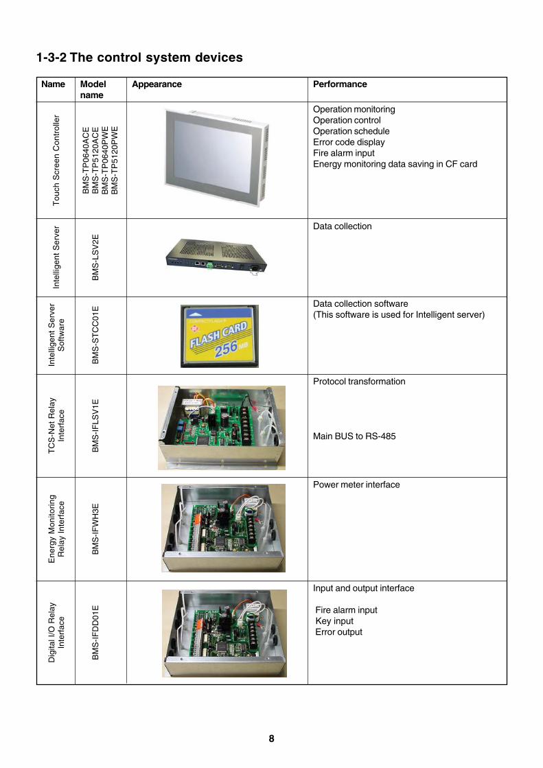
Operation monitoringOperation controlOperation scheduleError code displayFire alarm inputEnergy monitoring data saving in CF card
Data collection
Data collection software(This software is used for Intelligent server)
Protocol transformation
Main BUS to RS-485
Power meter interface
Input and output interface
Fire alarm input Key input Error output
1-3-2 The control system devices
9
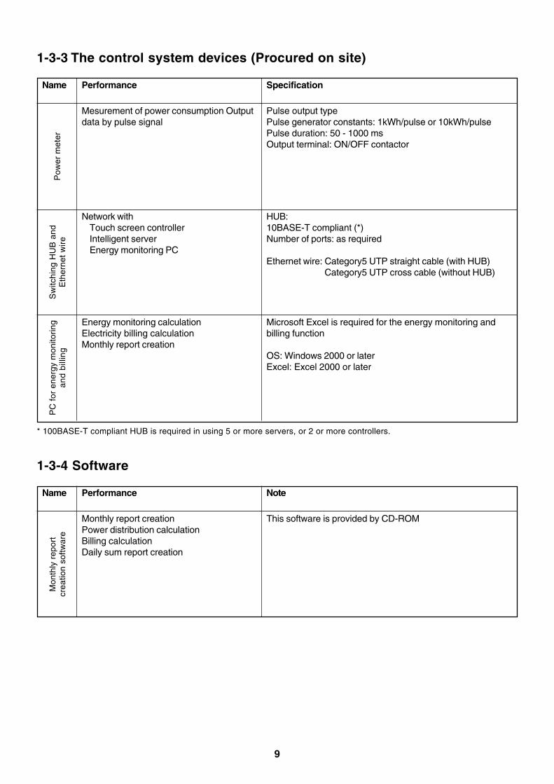
Name
Pow
er m
eter
Performance Specification
Pulse output typePulse generator constants: 1kWh/pulse or 10kWh/pulsePulse duration: 50 - 1000 msOutput terminal: ON/OFF contactor
1-3-3 The control system devices (Procured on site)
Mesurement of power consumption Outputdata by pulse signal
Sw
itchi
ng H
UB
and
Eth
erne
t w
ire
HUB:10BASE-T compliant (*)Number of ports: as required
Ethernet wire: Category5 UTP straight cable (with HUB)Category5 UTP cross cable (without HUB)
Network withTouch screen controllerIntelligent serverEnergy monitoring PC
PC
for
ene
rgy
mon
itorin
gan
d bi
lling
Microsoft Excel is required for the energy monitoring andbilling function
OS: Windows 2000 or laterExcel: Excel 2000 or later
Energy monitoring calculationElectricity billing calculationMonthly report creation
* 100BASE-T compliant HUB is required in using 5 or more servers, or 2 or more controllers.
Name
Mon
thly
rep
ort
crea
tion
softw
are
Performance Note
This software is provided by CD-ROM
1-3-4 Software
Monthly report creationPower distribution calculationBilling calculationDaily sum report creation
10
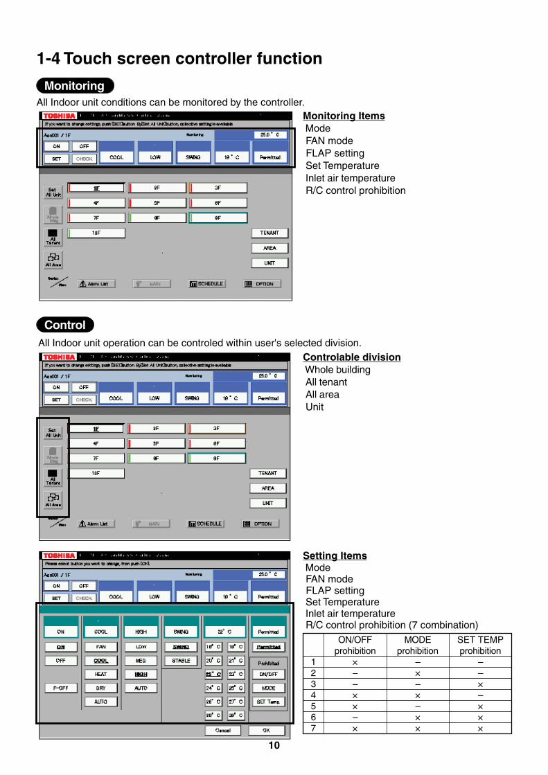
1-4 Touch screen controller function
All Indoor unit operation can be controled within user's selected division.
Monitoring Items Mode FAN mode FLAP setting Set Temperature Inlet air temperature R/C control prohibition
Controlable division Whole building All tenant All area Unit
Setting Items Mode FAN mode FLAP setting Set Temperature Inlet air temperature R/C control prohibition (7 combination)
MonitoringAll Indoor unit conditions can be monitored by the controller.
Control
1234567
ON/OFFprohibition
×––××–×
MODEprohibition
–×–×–××
SET TEMPprohibition
––×–×××
11
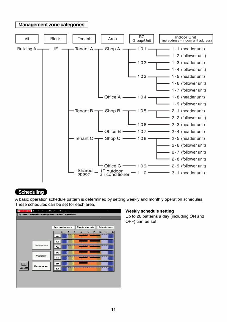
A basic operation schedule pattern is determined by setting weekly and monthly operation schedules.These schedules can be set for each area.
Weekly schedule settingUp to 20 patterns a day (including ON andOFF) can be set.
Scheduling
All Block Tenant Area RC Group/Unit
Indoor Unit (line address + indoor unit address)
Building A 1 - 1 (header unit)
1 - 2 (follower unit)
1 - 3 (header unit)
1 - 4 (follower unit)
1 - 5 (header unit)
1 - 6 (follower unit)
1 - 7 (follower unit)
1 - 8 (header unit)
1 - 9 (follower unit)
2 - 1 (header unit)
2 - 2 (follower unit)
2 - 3 (header unit)
2 - 4 (header unit)
2 - 5 (header unit)
2 - 6 (follower unit)
2 - 7 (follower unit)
2 - 8 (follower unit)
2 - 9 (follower unit)
3 - 1 (header unit)
1F 1 0 1
1 0 2
1 0 3
1 0 4
1 0 5
1 0 6
1 0 7
1 0 8
1 0 9
1 1 0
Shop A
Office A
Shop B
Office B
Shop C
Office C
Tenant A
Tenant B
Tenant C
Sharedspace
1F outdoorair conditioner
Management zone categories
12
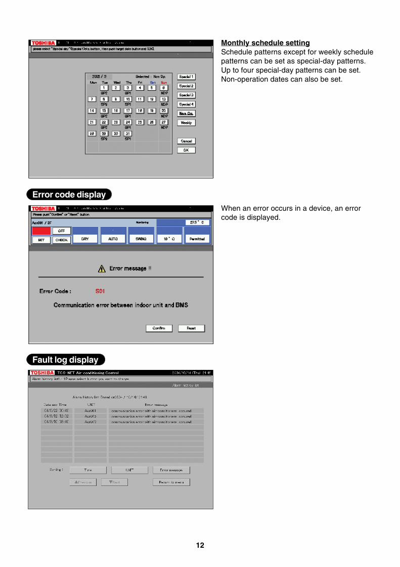
Monthly schedule settingSchedule patterns except for weekly schedulepatterns can be set as special-day patterns.Up to four special-day patterns can be set.Non-operation dates can also be set.
When an error occurs in a device, an errorcode is displayed.
Error code display
Fault log display
13
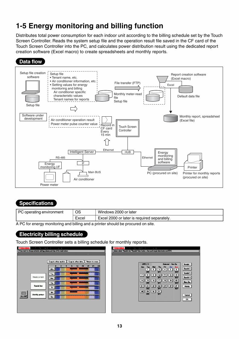
PC operating environment
1-5 Energy monitoring and billing functionDistributes total power consumption for each indoor unit according to the billing schedule set by the TouchScreen Controller. Reads the system setup file and the operation result file saved in the CF card of theTouch Screen Controller into the PC, and calculates power distribution result using the dedicated reportcreation software (Excel macro) to create spreadsheets and monthly reports.
Excel
HUB
IF
Ethernet
Ethernet
RS-485
Main BUS
Setup file creation software
Setup file
Software under development
Setup file• Tenant name, etc.• Air conditioner information, etc.• Setting values for energy monitoring and billing Air conditioner specific characteristic values Tenant names for reports
File transfer (FTP)
Monthly meter-read fileSetup file
Report creation software (Excel macro)
Default data file
Air conditioner operation resultPower meter pulse counter value Record in
CF cardEvery 15 min
Touch Screen Controller
Monthly report, spreadsheet(Excel file)
Intelligent Server
Energy monitoring I/F
Power meter
Air conditioner
Energy monitoring and billing software
PC (procured on site)
Printer
Printer for monthly reports (procured on site)
Windows 2000 or later
Excel 2000 or later is required separately.
OS
ExcelA PC for energy monitoring and billing and a printer should be procured on site.
Touch Screen Controller sets a billing schedule for monthly reports.
Data flow
Specifications
Electricity billing schedule
14
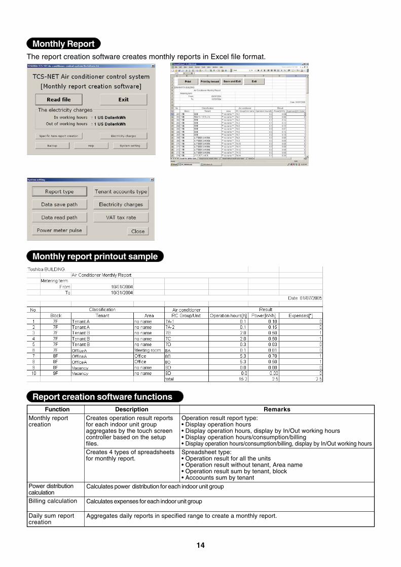
The report creation software creates monthly reports in Excel file format.
FunctionMonthly reportcreation
Power distributioncalculationBilling calculation
Daily sum reportcreation
RemarksOperation result report type:• Display operation hours• Display operation hours, display by In/Out working hours• Display operation hours/consumption/billing• Display operation hours/consumption/billing, display by In/Out working hoursSpreadsheet type:• Operation result for all the units• Operation result without tenant, Area name• Operation result sum by tenant, block• Accoounts sum by tenant
DescriptionCreates operation result reportsfor each indoor unit groupaggregates by the touch screencontroller based on the setupfiles.Creates 4 types of spreadsheetsfor monthly report.
Aggregates daily reports in specified range to create a monthly report.
Monthly Report
Monthly report printout sample
Report creation software functions
Calculates power distribution for each indoor unit group
Calculates expenses for each indoor unit group
15
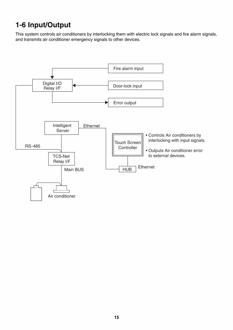
1-6 Input/OutputThis system controls air conditioners by interlocking them with electric lock signals and fire alarm signals,and transmits air conditioner emergency signals to other devices.
HUB
Intelligent Server
Ethernet
Ethernet
Air conditioner
Digital I/ORelay I/F Door-lock input
RS-485
Main BUS
TCS-Net Relay I/F
Fire alarm input
Error output
Touch ScreenController
• Controls Air conditioners by interlocking with input signals.
• Outputs Air conditioner error to external devices.

16
17
2
SYSTEM CONFIGURATION
2-1 Touch screen controller system configuration
18
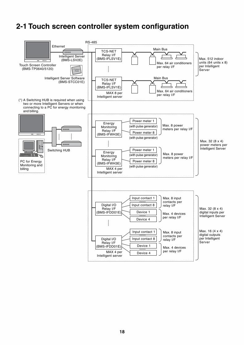
2-1 Touch screen controller system configuration
CompactFlash
Ethernet
InteIligent Server(BMS-LSV2E)
Touch Screen Controller(BMS-TP0640/5120)
Intelligent Server Software(BMS-STCC01E)
(*) A Switching HUB is required when usingtwo or more Intelligent Servers or whenconnecting to a PC for energy monitoringand billing.
PC for EnergyMonitoring andbilling
Switching HUB
TCS-NETRelay I/F
(BMS-IFLSV1E)
TCS-NETRelay I/F
(BMS-IFLSV1E)
MAX 8 perIntelligent server
EnergyMonitoringRelay I/F
(BMS-IFWH3E)
EnergyMonitoringRelay I/F
(BMS-IFWH3E)
Digital I/ORelay I/F
(BMS-IFDD01E)
Digital I/ORelay I/F
(BMS-IFDD01E)
RS-485
Main Bus
Max. 64 air conditionersper relay I/F
Max. 64 air conditionersper relay I/F
Max. 8 powermeters per relay I/F
Max. 8 powermeters per relay I/F
Max. 8 inputcontacts perrelay I/F
Max. 4 devicesper relay I/F
Max. 8 inputcontacts perrelay I/F
Max. 4 devicesper relay I/F
Max. 512 indoorunits (64 units x 8)per IntelligentServer
Max. 32 (8 x 4)power meters perIntelligent Server
Max. 32 (8 x 4)digital inputs perIntelligent Server
Max. 16 (4 x 4)digital outputsper IntelligentServer
Power meter 1
Power meter 8
(with pulse generator)
Input contact 1
Input contact 8
Device 1
Device 4
Main Bus
(with pulse generator)
(with pulse generator)
(with pulse generator)
Power meter 1
Power meter 8
Input contact 1
Input contact 8
Device 1
Device 4
MAX 4 perIntelligent server
MAX 4 perIntelligent server
19
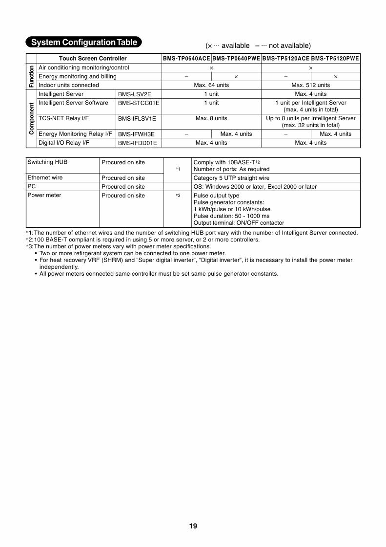
System Configuration Table
Air conditioning monitoring/control
Energy monitoring and billing
Indoor units connected
Intelligent Server
Intelligent Server Software
TCS-NET Relay I/F
Energy Monitoring Relay I/F
Digital I/O Relay I/F
Touch Screen Controller BMS-TP0640ACE BMS-TP0640PWE BMS-TP5120ACE BMS-TP5120PWE
×
– ×
Max. 64 units
1 unit
1 unit
Max. 8 units
– Max. 4 units
Max. 4 units
Func
tion
BMS-LSV2E
BMS-STCC01E
BMS-IFLSV1E
BMS-IFWH3E
BMS-IFDD01E
Co
mp
on
ent
×
– ×
Max. 512 units
Max. 4 units
1 unit per Intelligent Server(max. 4 units in total)
Up to 8 units per Intelligent Server(max. 32 units in total)
– Max. 4 units
Max. 4 units
(× ... available – ... not available)
Switching HUB
Ethernet wire
PC
Power meter
Procured on site
Procured on site
Procured on site
Procured on site
*1
*3
Category 5 UTP straight wire
OS: Windows 2000 or later, Excel 2000 or later
Pulse output typePulse generator constants:1 kWh/pulse or 10 kWh/pulsePulse duration: 50 - 1000 msOutput terminal: ON/OFF contactor
Comply with 10BASE-T*2
Number of ports: As required
*1:The number of ethernet wires and the number of switching HUB port vary with the number of Intelligent Server connected.*2:100 BASE-T compliant is required in using 5 or more server, or 2 or more controllers.*3:The number of power meters vary with power meter specifications.
• Two or more refirgerant system can be connected to one power meter.• For heat recovery VRF (SHRM) and “Super digital inverter”, “Digital inverter”, it is necessary to install the power meter
independently.• All power meters connected same controller must be set same pulse generator constants.
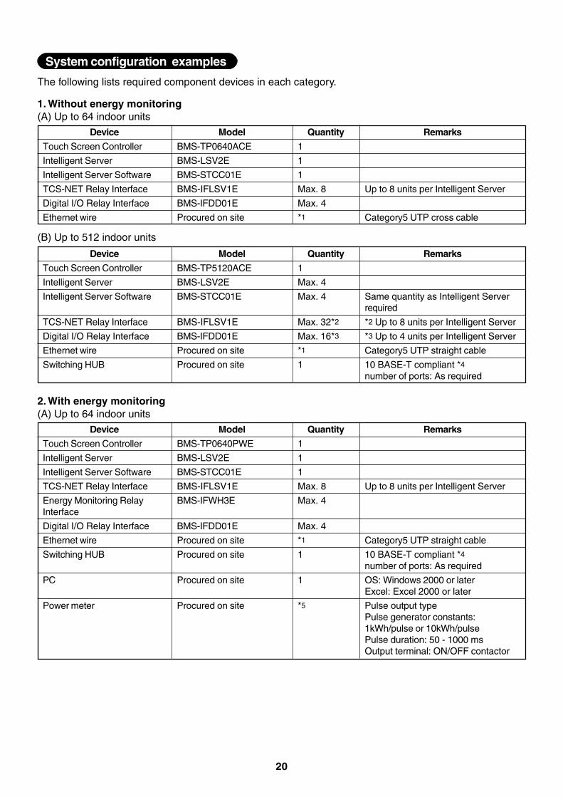
20
The following lists required component devices in each category.
1. Without energy monitoring(A) Up to 64 indoor units
Device
Touch Screen Controller
Intelligent Server
Intelligent Server Software
TCS-NET Relay Interface
Digital I/O Relay Interface
Ethernet wire
Remarks
Up to 8 units per Intelligent Server
Category5 UTP cross cable
Model
BMS-TP0640ACE
BMS-LSV2E
BMS-STCC01E
BMS-IFLSV1E
BMS-IFDD01E
Procured on site
Quantity
1
1
1
Max. 8
Max. 4
*1
(B) Up to 512 indoor units
Device
Touch Screen Controller
Intelligent Server
Intelligent Server Software
TCS-NET Relay Interface
Digital I/O Relay Interface
Ethernet wire
Switching HUB
Remarks
Same quantity as Intelligent Serverrequired
*2 Up to 8 units per Intelligent Server
*3 Up to 4 units per Intelligent Server
Category5 UTP straight cable
10 BASE-T compliant *4
number of ports: As required
Model
BMS-TP5120ACE
BMS-LSV2E
BMS-STCC01E
BMS-IFLSV1E
BMS-IFDD01E
Procured on site
Procured on site
Quantity
1
Max. 4
Max. 4
Max. 32*2
Max. 16*3
*1
1
2. With energy monitoring(A) Up to 64 indoor units
Device
Touch Screen Controller
Intelligent Server
Intelligent Server Software
TCS-NET Relay Interface
Energy Monitoring RelayInterface
Digital I/O Relay Interface
Ethernet wire
Switching HUB
PC
Power meter
Remarks
Up to 8 units per Intelligent Server
Category5 UTP straight cable
10 BASE-T compliant *4
number of ports: As required
OS: Windows 2000 or laterExcel: Excel 2000 or later
Pulse output typePulse generator constants:1kWh/pulse or 10kWh/pulsePulse duration: 50 - 1000 msOutput terminal: ON/OFF contactor
Model
BMS-TP0640PWE
BMS-LSV2E
BMS-STCC01E
BMS-IFLSV1E
BMS-IFWH3E
BMS-IFDD01E
Procured on site
Procured on site
Procured on site
Procured on site
Quantity
1
1
1
Max. 8
Max. 4
Max. 4
*1
1
1
*5
System configuration examples
21
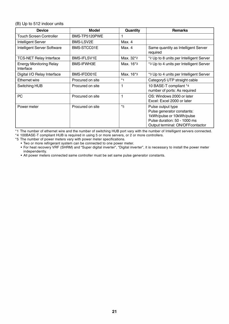
(B) Up to 512 indoor units
Device
Touch Screen Controller
Intelligent Server
Intelligent Server Software
TCS-NET Relay Interface
Energy Monitoring RelayInterface
Digital I/O Relay Interface
Ethernet wire
Switching HUB
PC
Power meter
Remarks
Same quantity as Intelligent Serverrequired
*2 Up to 8 units per Intelligent Server
*3 Up to 4 units per Intelligent Server
*3 Up to 4 units per Intelligent Server
Category5 UTP straight cable
10 BASE-T compliant *4
number of ports: As required
OS: Windows 2000 or laterExcel: Excel 2000 or later
Pulse output typePulse generator constants:1kWh/pulse or 10kWh/pulsePulse duration: 50 - 1000 msOutput terminal: ON/OFFcontactor
Model
BMS-TP5120PWE
BMS-LSV2E
BMS-STCC01E
BMS-IFLSV1E
BMS-IFWH3E
BMS-IFDD01E
Procured on site
Procured on site
Procured on site
Procured on site
Quantity
1
Max. 4
Max. 4
Max. 32*2
Max. 16*3
Max. 16*3
*1
1
1
*5
*1 The number of ethernet wire and the number of switching HUB port vary with the number of Intelligent servers connected.*4 100BASE-T compliant HUB is required in using 5 or more servers, or 2 or more controllers.*5 The number of power meters vary with power meter specifications.
• Two or more refirgerant system can be connected to one power meter.• For heat recovery VRF (SHRM) and “Super digital inverter”, “Digital inverter”, it is necessary to install the power meter
independently.• All power meters connected same controller must be set same pulse generator constants.

22
23
3
INSTALLATION
3-1 Installation work flow3-2 Setup file data preparation
3-2-1 Control wiring diagram (Connection example)3-2-2 Power meter wiring diagram (Connection example)3-2-3 Air conditioner address table3-2-4 Schedule table
3-3 Setup file creation3-3-1 Setup file creation software (Excel macro)3-3-2 Setup file contents
3-4 Control system Installation3-4-1 External view3-4-2 Installation method3-4-3 Device specifications
3-5 Wiring3-5-1 Wiring specifications3-5-2 Wiring diagram
3-6 Network connection3-7 Control system configulation
24
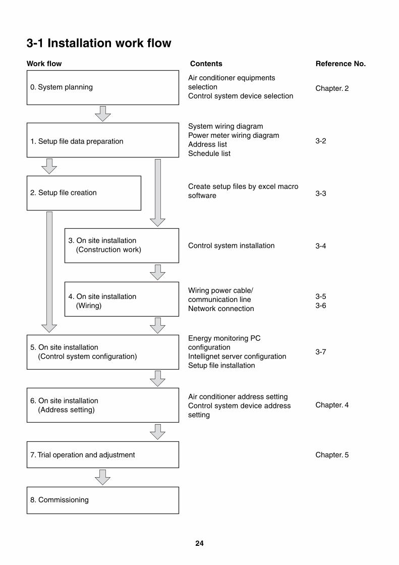
3-1 Installation work flow
Work flow
0. System planning
Contents Reference No.
1. Setup file data preparation
2. Setup file creation
3. On site installation(Construction work)
4. On site installation(Wiring)
5. On site installation(Control system configuration)
6. On site installation(Address setting)
7. Trial operation and adjustment
8. Commissioning
Air conditioner equipmentsselectionControl system device selection
System wiring diagramPower meter wiring diagramAddress listSchedule list
Create setup files by excel macrosoftware
Control system installation
Wiring power cable/communication lineNetwork connection
Energy monitoring PCconfigurationIntellignet server configurationSetup file installation
Air conditioner address settingControl system device addresssetting
Chapter. 2
3-2
3-3
3-4
3-53-6
3-7
Chapter. 4
Chapter. 5
25
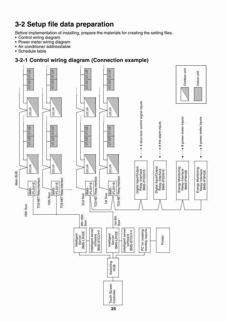
3-2 Setup file data preparationBefore implementation of installing, prepare the materials for creating the setting files.• Control wiring diagram• Power meter wiring diagram• Air conditioner addresstable• Schedule table
3-2-1 Control wiring diagram (Connection example)
U1,
U2
U1,
U2
U1,
U2
U1,
U2
U1,
U2
U1,
U2
U1,
U2
U1,
U2
U1,
U2
U1,
U2
U1,
U2
U1,
U2
U1,
U2
U1,
U2
U1,
U2
U1,
U2
U3,
U4
U3,
U4
U3,
U4
U3,
U4
U3,
U4
U3,
U4
U3,
U4
U3,
U4
16th
flo
or
Tou
ch S
cre
en
Con
trol
ler
Sw
itchi
ngH
UB
8 do
or-l
ock
cont
rol s
igna
l inp
uts
8 fir
e al
arm
inpu
ts
8 po
wer
met
er in
puts
1st
-8th
floor
9th
-16
thflo
or
1st
floor
2nd
floor
15th
flo
or Dig
ital I
nput
/Out
put
Re
lay
Inte
rfa
ceB
MS
-IF
DD
01
E
Ene
rgy
Mon
itori
ngR
ela
y In
terf
ace
BM
S-I
FW
H3E
Ene
rgy
Mon
itori
ngR
ela
y In
terf
ace
BM
S-I
FW
H3E
Inte
llige
ntS
erv
er
BM
S-L
SV
2E
PC
fo
r cr
ea
ting
mo
nth
ly r
ep
ort
s
Pri
nte
r
Mai
n B
US
TCS
-NE
T R
elay
Inte
rface
TCS
-NE
T R
elay
Inte
rface
TCS
-NE
T R
elay
Inte
rface
TCS
-NE
T R
elay
Inte
rface
Out
door
uni
t
Indo
or u
nit
Dig
ital I
nput
/Out
put
Re
lay
Inte
rfa
ceB
MS
-IF
DD
01
E
BM
S-
IFLS
V1E
Inte
llige
nt s
erve
rso
ftw
are
BM
S-S
TC
C
Inte
llige
ntS
erv
er
BM
S-L
SV
2E
Inte
llige
nt s
erve
rso
ftw
are
BM
S-S
TC
C
BM
S-
IFLS
V1E
BM
S-
IFLS
V1E
BM
S-
IFLS
V1E
8 po
wer
met
er in
puts
26
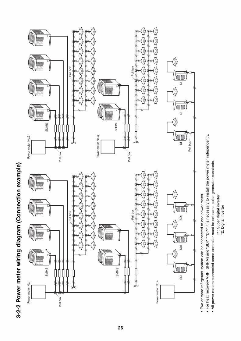
3-2-
2 P
ow
er m
eter
wir
ing
dia
gra
m (
Co
nn
ecti
on
exa
mp
le)
•Tw
o or
mor
e re
firge
rant
sys
tem
can
be
conn
ecte
d to
one
pow
er m
eter
.
•F
or h
eat
reco
very
VR
F (
SH
RM
) an
d “S
DI*
1 ” “
DI*
2 ” it
is n
eces
sary
to
inst
all t
he p
ower
met
er in
depe
nden
tly.
•A
ll po
wer
met
ers
conn
ecte
d sa
me
cont
rolle
r m
ust
be s
et s
ame
puls
e ge
nera
tor
cons
tant
s.
*1:
Sup
er d
igita
l inv
erte
r*2
: D
igita
l inv
erte
r
Pul
l box
Pul
l box
Pow
er m
eter
No.
1
SM
MS
SM
MS
Pow
er m
eter
No.
4
SD
I
Pul
l box
SD
IS
DI
DI
DI
DI
Pul
l box
Pul
l box
Pul
l box
Pul
l box
Pow
er m
eter
No.
3
SH
RM
Pul
l box
Pow
er m
eter
No.
2
SM
MS
27
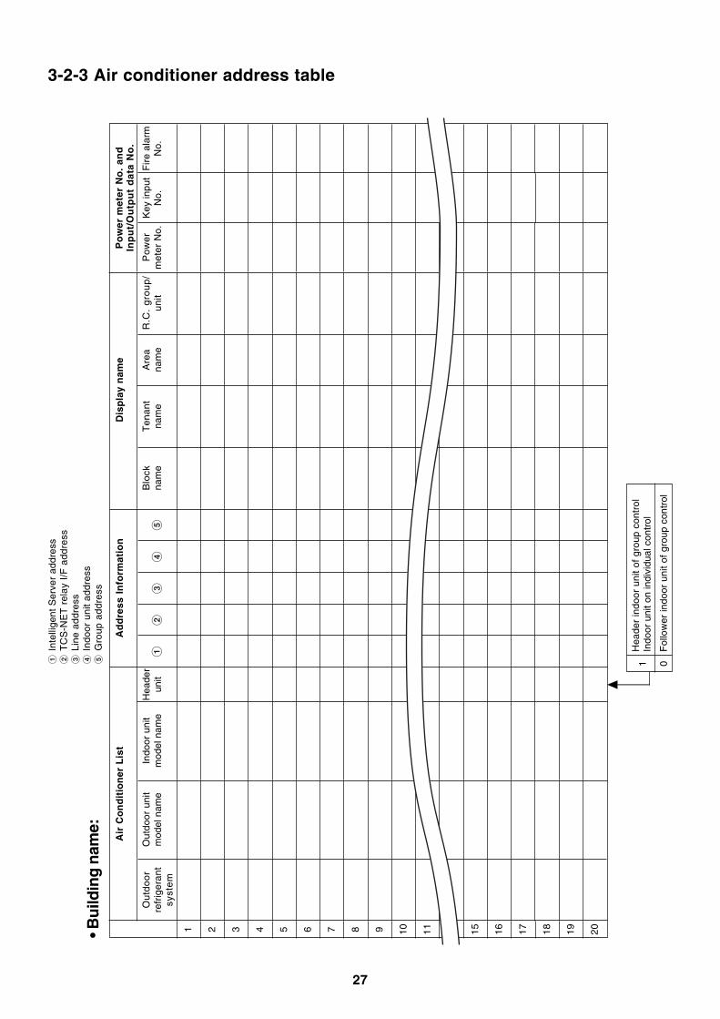
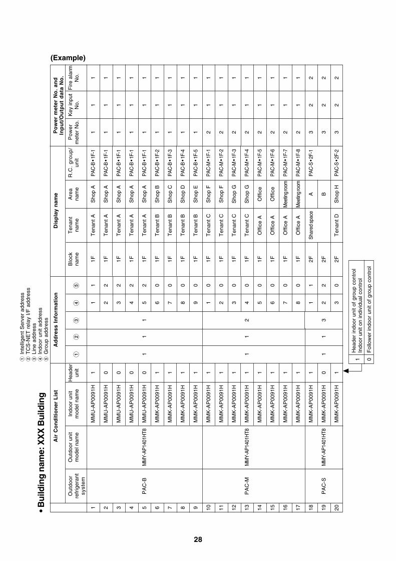
3-2-3 Air conditioner address table• B
uild
ing
nam
e:
Key
inpu
tN
o.
Po
wer
met
er N
o.
and
Inp
ut/
Ou
tpu
t d
ata
No
.
Pow
erm
eter
No.
1 2 3 4 5 6 7 8 9 10 11 12 15 16 17 18 19 20
Ou
tdo
or
refr
iger
ant
syst
em
Out
door
uni
tm
odel
nam
eR
.C.
gro
up
/u
nit
Indo
or u
nit
mod
el n
ame
Hea
der
unit
Air
Co
nd
itio
ner
Lis
t
Blo
ckna
me
Ten
ant
nam
eA
rea
nam
e
Ad
dre
ss I
nfo
rmat
ion
Dis
pla
y n
ame
Int
ellig
ent
Ser
ver
addr
ess
TC
S-N
ET
rel
ay I
/F a
ddre
ss L
ine
addr
ess
Ind
oor
unit
addr
ess
Gro
up a
ddre
ss
Fire
ala
rmN
o.
Hea
der
indo
or u
nit
of g
roup
con
trol
Indo
or u
nit o
n in
divi
dual
con
trol
Fol
low
er in
door
uni
t of
gro
up c
ontr
ol
1 0
28
(Example)
• Bu
ildin
g n
ame:
XX
X B
uild
ing
Key
inpu
tN
o. 1 1 1 1 1 1 1 1 1 1 1 1 1 1 1 1 1 2 2 2
Po
wer
met
er N
o.
and
Inp
ut/
Ou
tpu
t d
ata
No
.
Pow
erm
eter
No.
1 1 1 1 1 1 1 1 1 2 2 2 2 2 2 2 2 3 3 3
Out
door
uni
tm
odel
nam
e
MM
Y-AP
1401
HT8
MM
Y-AP
1401
HT8
MM
Y-AP
1401
HT8
R.C
. g
rou
p/
un
it
PA
C-B
• 1F
-1
PA
C-B
• 1F
-1
PA
C-B
• 1F
-1
PA
C-B
• 1F
-1
PA
C-B
• 1F
-1
PA
C-B
• 1F
-2
PA
C-B
• 1F
-3
PA
C-B
• 1F
-4
PA
C-B
• 1F
-5
PAC
-M •
1F-1
PAC
-M •
1F-2
PAC
-M •
1F-3
PAC
-M •
1F-4
PAC
-M •
1F-5
PAC
-M •
1F-6
PAC
-M •
1F-7
PAC
-M •
1F-8
PA
C-S
• 2F
-1
PA
C-S
• 2F
-2
Indo
or u
nit
mod
el n
ame
MM
U-A
P00
91H
MM
U-A
P00
91H
MM
U-A
P00
91H
MM
U-A
P00
91H
MM
U-A
P00
91H
MM
K-A
P00
91H
MM
K-A
P00
91H
MM
K-A
P00
91H
MM
K-A
P00
91H
MM
K-A
P00
91H
MM
K-A
P00
91H
MM
K-A
P00
91H
MM
K-A
P00
91H
MM
K-A
P00
91H
MM
K-A
P00
91H
MM
K-A
P00
91H
MM
K-A
P00
91H
MM
K-A
P00
91H
MM
K-A
P00
91H
MM
K-A
P00
91H
Hea
der
unit 1 0 0 0 0 1 1 1 1 1 1 1 1 1 1 1 1 1 0 1
Air
Co
nd
itio
ner
Lis
t
Blo
ckna
me
1F
1F
1F
1F
1F
1F
1F
1F
1F
1F
1F
1F
1F
1F
1F
1F
1F
2F
2F
2F
Ten
ant
nam
e
Ten
ant
A
Ten
ant
A
Ten
ant
A
Ten
ant
A
Ten
ant
A
Ten
ant
B
Ten
ant
B
Ten
ant
B
Ten
ant
B
Ten
ant
C
Ten
ant
C
Ten
ant
C
Ten
ant
C
Off
ice
A
Off
ice
A
Off
ice
A
Off
ice
A
Sha
red
spac
e
Ten
ant
D
Are
ana
me
Sho
p A
Sho
p A
Sho
p A
Sho
p A
Sho
p A
Sho
p B
Sho
p C
Sho
p D
Sho
p E
Sho
p F
Sho
p F
Sho
p G
Sho
p G
Off
ice
Off
ice
Mee
ting
room
Mee
ting
room
A B
Sho
p H
Ad
dre
ss I
nfo
rmat
ion
Dis
pla
y n
ame
1 2 3
1 2 3 4 5 6 7 8 9 1 2 3 4 5 6 7 8 1 2 3
1 2 2 2 2 0 0 0 0 0 0 0 0 0 0 0 0 1 2 0
1 1 1
1 1 1
Int
ellig
ent
Ser
ver
addr
ess
TC
S-N
ET
rel
ay I
/F a
ddre
ss L
ine
addr
ess
Ind
oor
unit
addr
ess
Gro
up a
ddre
ss
Fire
ala
rmN
o. 1 1 1 1 1 1 1 1 1 1 1 1 1 1 1 1 1 2 2 2
1 2 3 4 5 6 7 8 9 10 11 12 13 14 15 16 17 18 19 20
Ou
tdo
or
refr
iger
ant
syst
em
PA
C-B
PA
C-M
PA
C-S
Hea
der
indo
or u
nit
of g
roup
con
trol
Indo
or u
nit o
n in
divi
dual
con
trol
Fol
low
er in
door
uni
t of
gro
up c
ontr
ol
1 0
29
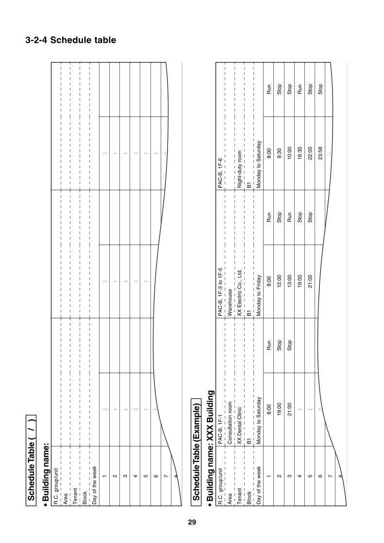
3-2-4 Schedule tableS
ched
ule
Tab
le (
/
)
• Bu
ildin
g n
ame:
R.C
. gr
oup/
unit
Are
a
Ten
ant
Blo
ck
Day
of
the
wee
k
1 2 3 4 5 6 7 8
: : : : : : : :
: : : : : : : :
: : : : : : : :
Sch
edul
e Ta
ble
(Exa
mpl
e)
• Bu
ildin
g n
ame:
XX
X B
uild
ing
R.C
. gr
oup/
unit
Are
a
Ten
ant
Blo
ck
Day
of
the
wee
k
1 2 3 4 5 6 7 8
PA
C-B
, 1F
-1
Con
sulta
tion
room
XX
Den
tal C
linic
B1
Mon
day
to S
atur
day
8:00
19:0
0
21:0
0
: : : : :
Run
Sto
p
Sto
p
PA
C-B
, 1F
-3 t
o 1F
-5
War
ehou
se
XX
Ele
ctric
Co.
, Ltd
.
B1
Mon
day
to F
rida
y
8:00
12:0
0
13:0
0
19:0
0
21:0
0
: : :
Run
Sto
p
Run
Sto
p
Sto
p
PA
C-B
, 1F
-6
Nig
ht-d
uty
room
B1
Mon
day
to S
atur
day
8:00
9:30
10:0
0
16:3
0
22:0
0
23:5
8
: :
Run
Sto
p
Sto
p
Run
Sto
p
Sto
p
30
HUBEthernet Ethernet
RS-485
Main BUS
Excel
Setup file creation software for Touch Screen Controller
Default data fileProduct information file
Provided from installation company and building management company.
Setup fileSetup file• Tenant name, etc.• Air conditioner information, etc.• Setting values for energy monitoring and billing Air conditioner specific characteristic values Tenant names for reports Record in CF card
Touch Screen Controller
Intelligent Server
Energy monitoring I/F
Power meterAir conditioner
Air conditioner informationLocation, indoor unit group setting,
control address (I/F, indoor, outdoor), device type, product model, number of devices
Device information Power meter No., pulse constant, fire alarm/door-lock input No., emergency output No.
Control display information Block/area/tenant/R.C. Group, unit names
Building operation information Meter read date Schedule (operation, charging)
Set by scheduler function of Touch Screen Controller.
Power distribution software
Printer
TCS-NET Relay I/F
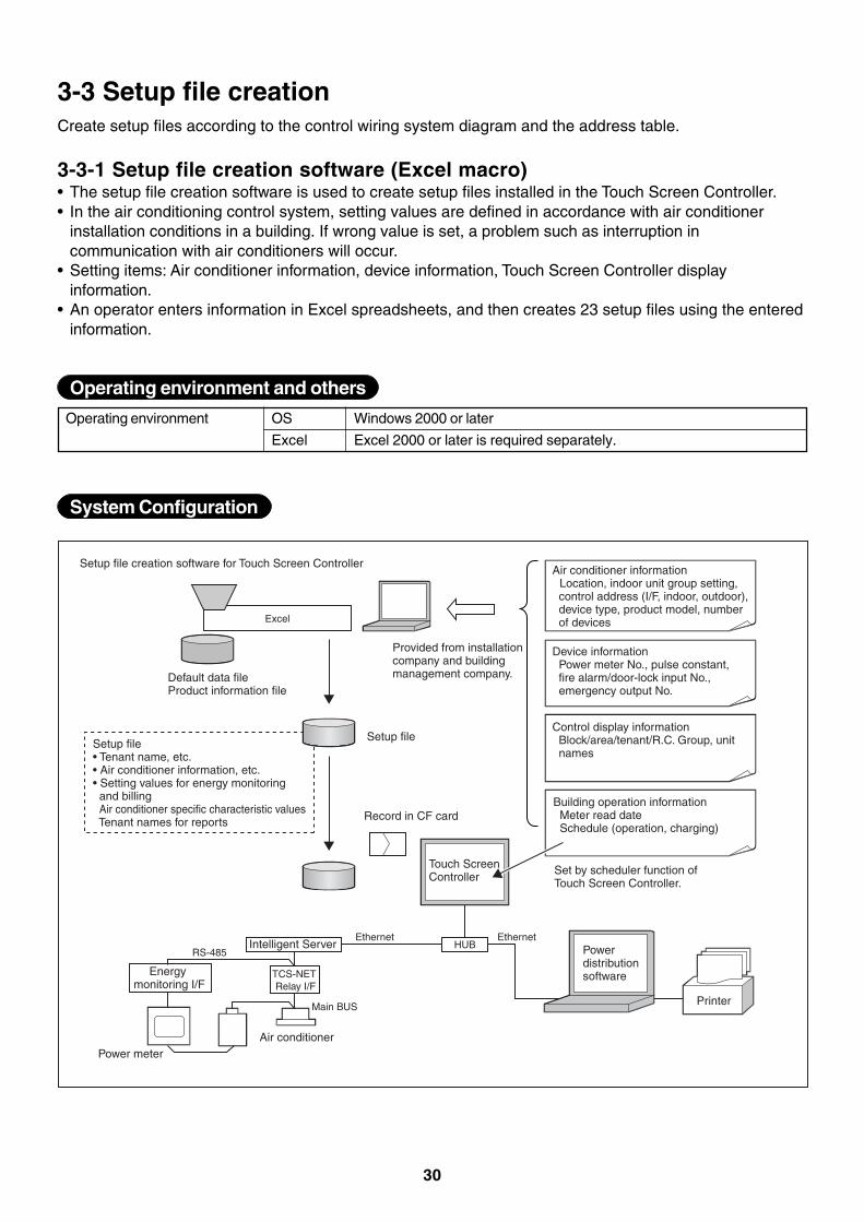
System Configuration
3-3 Setup file creationCreate setup files according to the control wiring system diagram and the address table.
3-3-1 Setup file creation software (Excel macro)• The setup file creation software is used to create setup files installed in the Touch Screen Controller.• In the air conditioning control system, setting values are defined in accordance with air conditioner
installation conditions in a building. If wrong value is set, a problem such as interruption incommunication with air conditioners will occur.
• Setting items: Air conditioner information, device information, Touch Screen Controller displayinformation.
• An operator enters information in Excel spreadsheets, and then creates 23 setup files using the enteredinformation.
Operating environment Windows 2000 or later
Excel 2000 or later is required separately.
OS
Excel
Operating environment and others
31
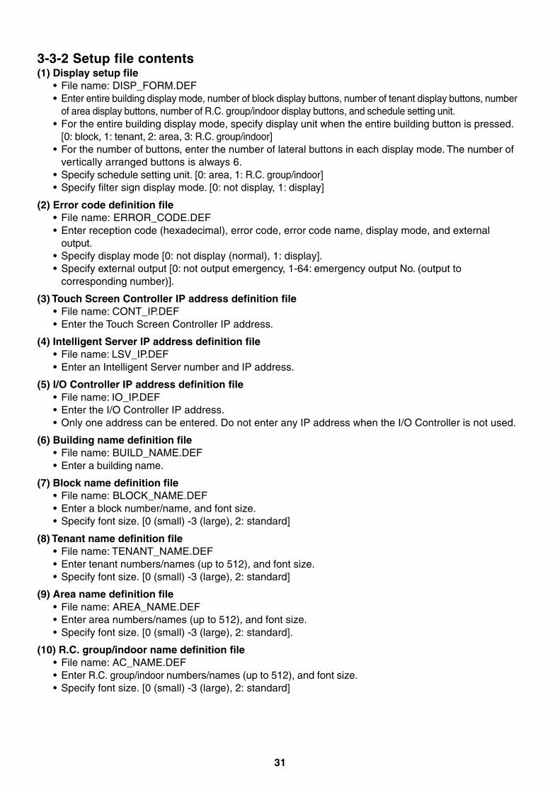
3-3-2 Setup file contents(1) Display setup file
• File name: DISP_FORM.DEF• Enter entire building display mode, number of block display buttons, number of tenant display buttons, number
of area display buttons, number of R.C. group/indoor display buttons, and schedule setting unit.• For the entire building display mode, specify display unit when the entire building button is pressed.
[0: block, 1: tenant, 2: area, 3: R.C. group/indoor]• For the number of buttons, enter the number of lateral buttons in each display mode. The number of
vertically arranged buttons is always 6.• Specify schedule setting unit. [0: area, 1: R.C. group/indoor]• Specify filter sign display mode. [0: not display, 1: display]
(2) Error code definition file• File name: ERROR_CODE.DEF• Enter reception code (hexadecimal), error code, error code name, display mode, and external
output.• Specify display mode [0: not display (normal), 1: display].• Specify external output [0: not output emergency, 1-64: emergency output No. (output to
corresponding number)].
(3) Touch Screen Controller IP address definition file• File name: CONT_IP.DEF• Enter the Touch Screen Controller IP address.
(4) Intelligent Server IP address definition file• File name: LSV_IP.DEF• Enter an Intelligent Server number and IP address.
(5) I/O Controller IP address definition file• File name: IO_IP.DEF• Enter the I/O Controller IP address.• Only one address can be entered. Do not enter any IP address when the I/O Controller is not used.
(6) Building name definition file• File name: BUILD_NAME.DEF• Enter a building name.
(7) Block name definition file• File name: BLOCK_NAME.DEF• Enter a block number/name, and font size.• Specify font size. [0 (small) -3 (large), 2: standard]
(8) Tenant name definition file• File name: TENANT_NAME.DEF• Enter tenant numbers/names (up to 512), and font size.• Specify font size. [0 (small) -3 (large), 2: standard]
(9) Area name definition file• File name: AREA_NAME.DEF• Enter area numbers/names (up to 512), and font size.• Specify font size. [0 (small) -3 (large), 2: standard].
(10) R.C. group/indoor name definition file• File name: AC_NAME.DEF• Enter R.C. group/indoor numbers/names (up to 512), and font size.• Specify font size. [0 (small) -3 (large), 2: standard]
32
(11) Door-lock input definition file• File name: KEY_CH.DEF• Enter door-lock input numbers (1-64), input device IDs, input channels, and signal logic (up to 64).• When no door-lock input is used, do not enter it.• An input device ID means the following:
0 to 7: I/O module device ID10: general-purpose input in the touch panel100 or more: digital I/O interface (Second digit: Intelligent Server No., first digit: Relay Interface No.)
• Specify signal logic. [0: negative logic, 1: positive logic]
(12) Fire alarm input definition file• File name: FIRE_CH.DEF• Enter fire alarm input numbers (1-64), input device IDs, input channels, and signal logic (up to 64).• When no fire alarm input is used, do not enter it.• An input device ID means the following:
0 to 7: I/O module device ID10: general-purpose input in the touch panel100 or more: digital I/O interface (Second digit: Intelligent Server No., first digit: Relay Interface No.)
• Specify signal logic. [0: negative logic, 1: positive logic]
(13) Emergency external output definition file• File name: EMGOUT_CH.DEF• Enter external emergency output numbers (1-64), output device IDs, and output channels (up to 64).• When no external emergency output is used, do not enter it.• An output device ID means the following:
0 to 7: I/O module device ID20: general-purpose output in the touch panel100 or more: digital I/O interface (Second digit: Intelligent Server No., first digit: Relay Interface No.)
(14) R.C. group/indoor setup file• File name: AC_MAP.DEF• R.C. group/indoor No., Intelligent Server No., Relay Interface No., outdoor system No., indoor unit
address, device type, block No., tenant No., area No., key No., fire alarm No.• Device type
0: SMMS, SHRM, 1: SDI, DI, 2: HA interface• Key No.
0: no door-lock interlocking, 1-64: When a signal is input from the number defined in (11), stopcommand is sent to the system.
• Fire alarm No.0: no fire alarm interlocking, 1-64: When a signal is input from the number defined in (12), stopcommand is sent to the system.
• Indoor unit set in this file is header unit only.
(15) Indoor unit group config file• File name: AC_GROUP.DEF• R.C. group/indoor No., Intelligent Server No., Relay Interface No., outdoor system No., indoor unit
address, device type, outdoor unit No., header/follower, tenant No.• Used for energy monitoring and billing. No data is provided when energy monitoring and billing is not
performed.
(16) Outdoor unit group config file• File name: OUT_GROUP.DEF• Outdoor unit No., Intelligent Server No., Relay Interface No., system No., outdoor unit address,
device type• Used for energy monitoring and billing. No data is provided when energy monitoring and billing is not
performed.
33
(17) Power meter input definition file• File name: WHM_CH.DEF• Power meter No. (1-64), interface address, channel No., pulse generator constants• Used for energy monitoring and billing. No data is provided when energy monitoring and billing is not
performed.• An interface address means the following:
1 to 31: energy monitoring interface100 or more: pulse counter interface (Second digit: Intelligent Server No., first digit: Relay InterfaceNo.)
• Pulse generator constants (kWh/pulse): Used by the energy monitoring and billing Excel macro, butnot used by the controller.
(18) Report setup file• File name: REPORT.DEF• Daily report limit time (meter-read time), Monthly report limit date
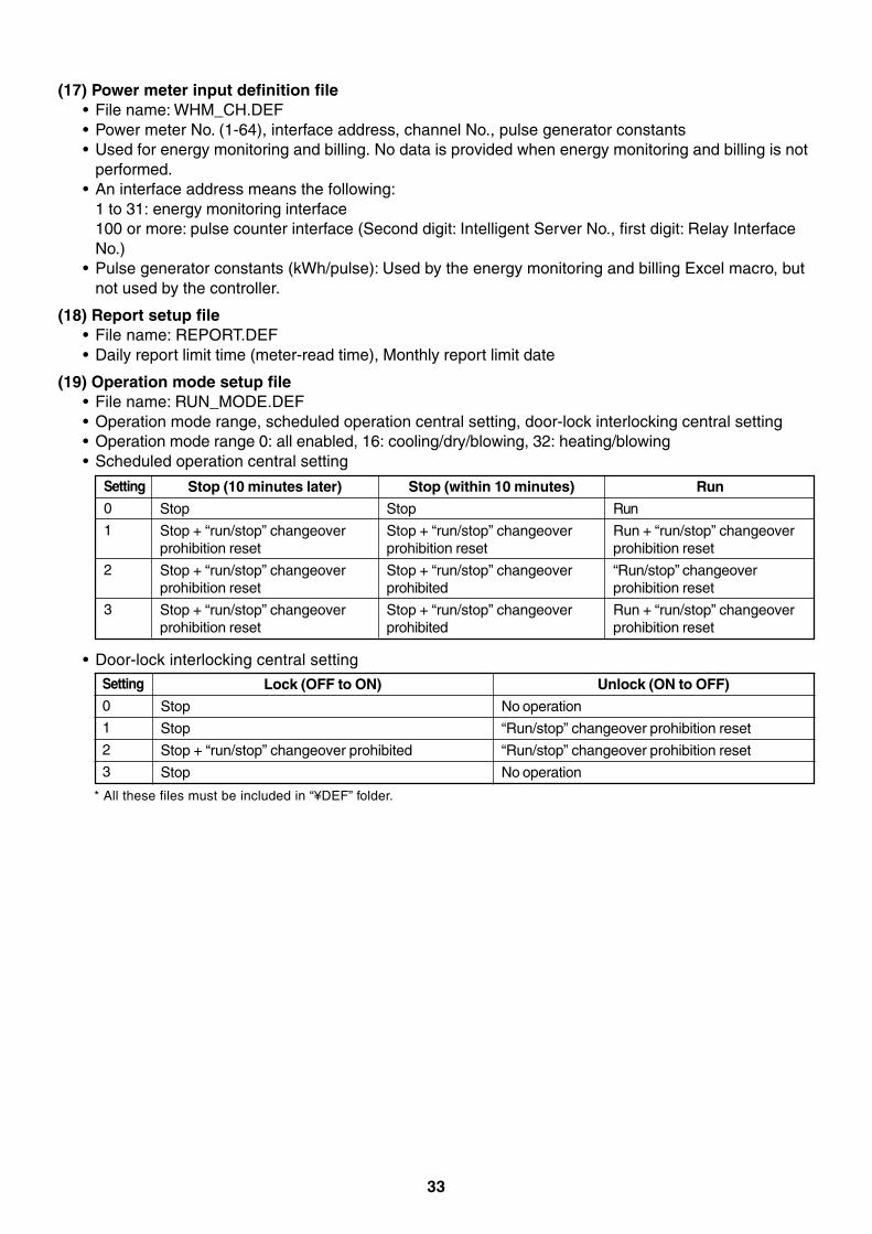
(19) Operation mode setup file• File name: RUN_MODE.DEF• Operation mode range, scheduled operation central setting, door-lock interlocking central setting• Operation mode range 0: all enabled, 16: cooling/dry/blowing, 32: heating/blowing• Scheduled operation central setting
Setting
0
1
2
3
Stop (10 minutes later)
Stop
Stop + “run/stop” changeoverprohibition reset
Stop + “run/stop” changeoverprohibition reset
Stop + “run/stop” changeoverprohibition reset
Stop (within 10 minutes)
Stop
Stop + “run/stop” changeoverprohibition reset
Stop + “run/stop” changeoverprohibited
Stop + “run/stop” changeoverprohibited
Run
Run
Run + “run/stop” changeoverprohibition reset
“Run/stop” changeoverprohibition reset
Run + “run/stop” changeoverprohibition reset
Setting
0
1
2
3
Lock (OFF to ON)
Stop
Stop
Stop + “run/stop” changeover prohibited
Stop
• Door-lock interlocking central setting
Unlock (ON to OFF)
No operation
“Run/stop” changeover prohibition reset
“Run/stop” changeover prohibition reset
No operation
* All these files must be included in “¥DEF” folder.
34
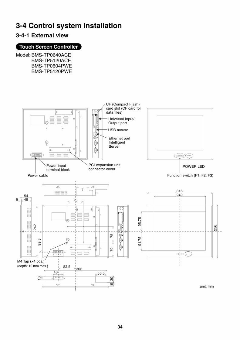
3-4 Control system installation3-4-1 External view
Model: BMS-TP0640ACEBMS-TP5120ACEBMS-TP0604PWEBMS-TP5120PWE
Touch Screen Controller
249
95.7
591
.75
256
193016
545 49
242
99.3
75
82.5302
55.548
7075
316
Function switch (F1, F2, F3)
PCI expansion unitconnector cover
Power inputterminal block
Power cable
Ethernet portIntelligentServer
USB mouse
CF (Compact Flash)card slot (CF card fordata files)
POWER LED
M4 Tap (×4 pcs.)(depth: 10 mm max.)
unit: mm
Universal Input/Output port
35
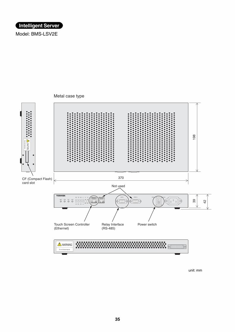
Model: BMS-LSV2E
Intelligent Server
CAUTIOND
o not remove.
WARNINGDo not decompose.
198
39 42
370
Not used
Touch Screen Controller(Ethernet)
Relay Interface(RS-485)
Power switch
CF (Compact Flash) card slot
Metal case type
unit: mm
36
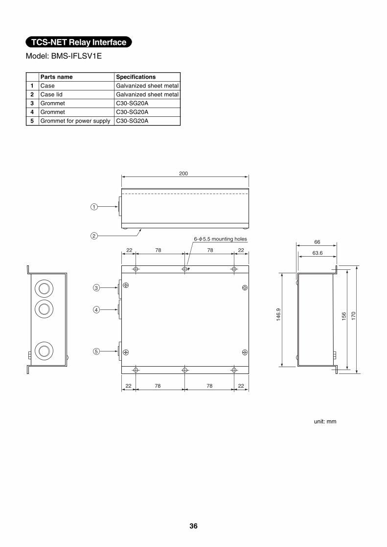
Model: BMS-IFLSV1E
TCS-NET Relay Interface
200
22787822
22787822
66
63.6
146.
9
156
170
6- 5.5 mounting holes
1
2
3
4
5
1
2
3
4
5
Parts name
Case
Case lid
Grommet
Grommet
Grommet for power supply
Specifications
Galvanized sheet metal
Galvanized sheet metal
C30-SG20A
C30-SG20A
C30-SG20A
unit: mm
37
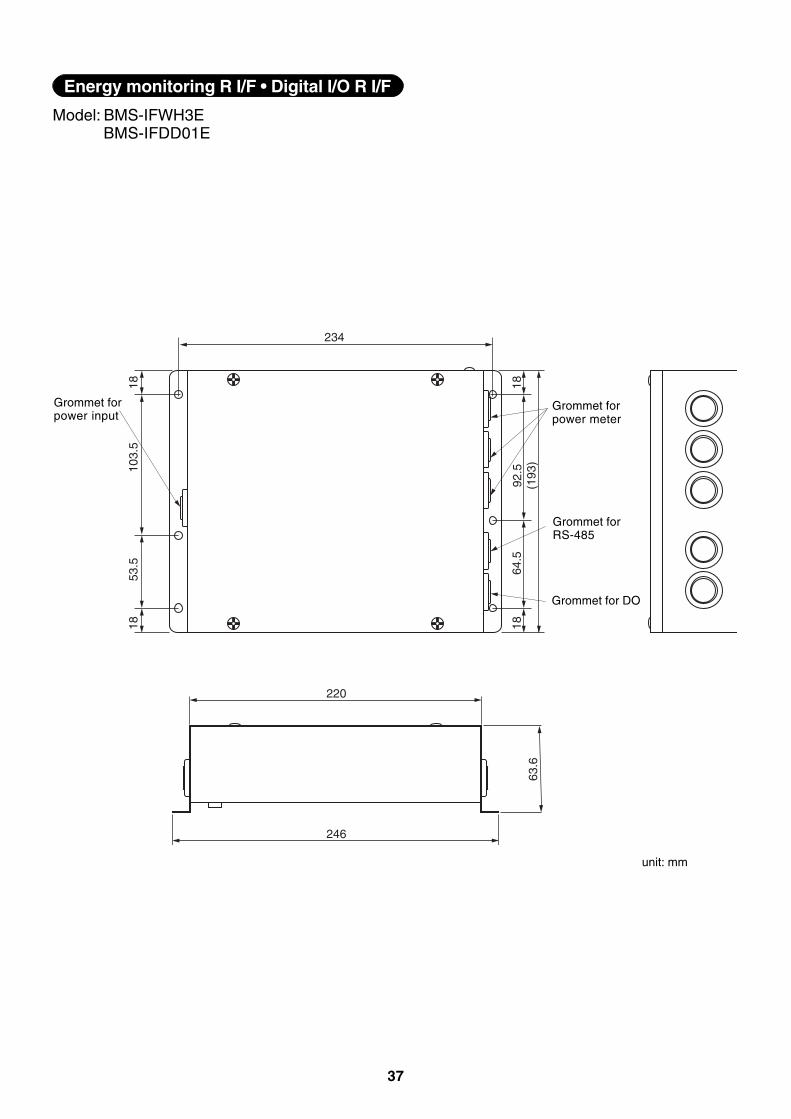
Model: BMS-IFWH3EBMS-IFDD01E
Energy monitoring R I/F • Digital I/O R I/F
234
1818
(193
)92
.564
.5
1818
53.5
103.
5
63.6
220
246
Grommet forpower input
Grommet forpower meter
Grommet forRS-485
Grommet for DO
unit: mm
38
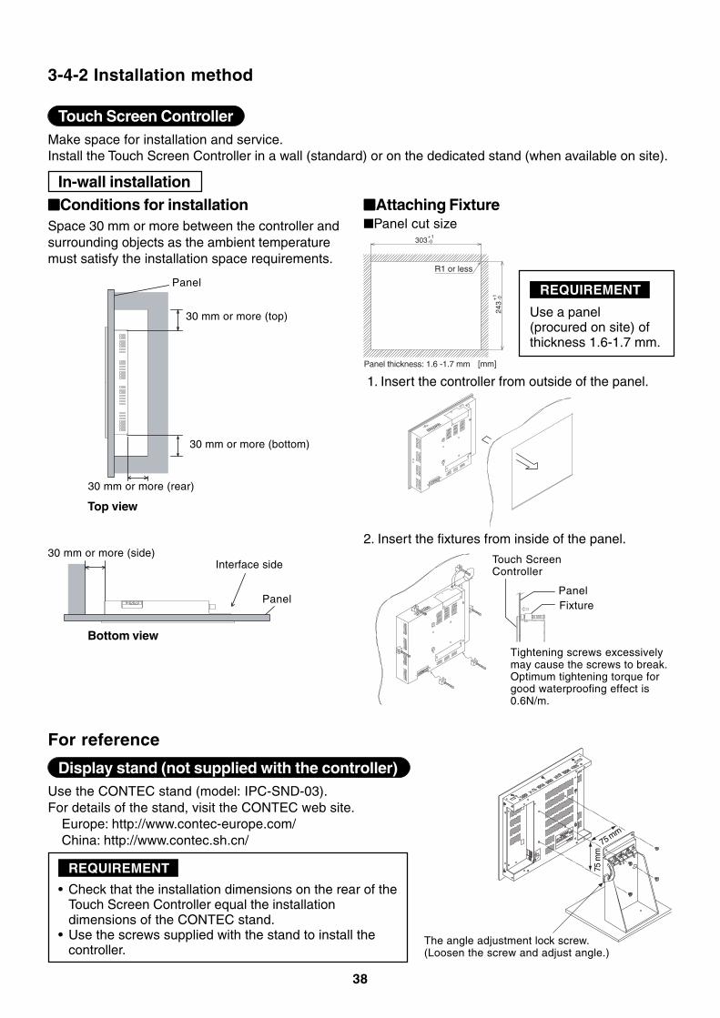
3-4-2 Installation method
Touch Screen ControllerMake space for installation and service.Install the Touch Screen Controller in a wall (standard) or on the dedicated stand (when available on site).
In-wall installation■■■■■Conditions for installationSpace 30 mm or more between the controller andsurrounding objects as the ambient temperaturemust satisfy the installation space requirements.
■■■■■Attaching Fixture
Panel
30 mm or more (top)
30 mm or more (bottom)
30 mm or more (rear)
30 mm or more (side)Interface side
Panel
Top view
Bottom view
1. Insert the controller from outside of the panel.
2. Insert the fixtures from inside of the panel.
Tightening screws excessivelymay cause the screws to break.Optimum tightening torque forgood waterproofing effect is0.6N/m.
Panel
Touch ScreenController
Fixture
■Panel cut size303
+1-0
243
+1
-0
R1 or less
[mm]Panel thickness: 1.6 -1.7 mm
REQUIREMENT
Use a panel(procured on site) ofthickness 1.6-1.7 mm.
For reference
Display stand (not supplied with the controller)Use the CONTEC stand (model: IPC-SND-03).For details of the stand, visit the CONTEC web site.
Europe: http://www.contec-europe.com/China: http://www.contec.sh.cn/
• Check that the installation dimensions on the rear of theTouch Screen Controller equal the installationdimensions of the CONTEC stand.
• Use the screws supplied with the stand to install thecontroller.
REQUIREMENT
The angle adjustment lock screw.(Loosen the screw and adjust angle.)
75 m
m
75 mm
39
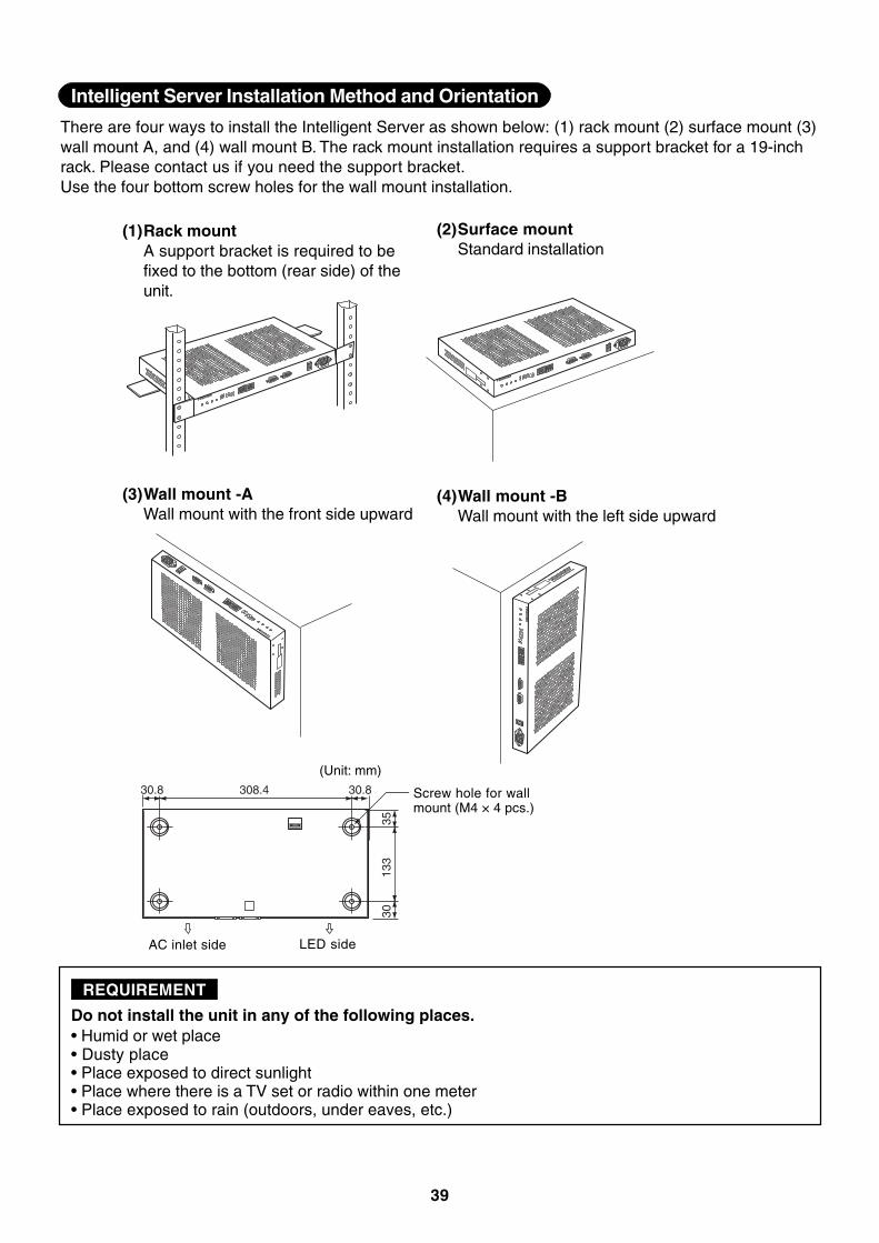
Do not install the unit in any of the following places.• Humid or wet place• Dusty place• Place exposed to direct sunlight• Place where there is a TV set or radio within one meter• Place exposed to rain (outdoors, under eaves, etc.)
REQUIREMENT
Intelligent Server Installation Method and Orientation
There are four ways to install the Intelligent Server as shown below: (1) rack mount (2) surface mount (3)wall mount A, and (4) wall mount B. The rack mount installation requires a support bracket for a 19-inchrack. Please contact us if you need the support bracket.Use the four bottom screw holes for the wall mount installation.
(4)Wall mount -BWall mount with the left side upward
(1)Rack mountA support bracket is required to befixed to the bottom (rear side) of theunit.
(2)Surface mountStandard installation
(3)Wall mount -AWall mount with the front side upward
308.4 30.830.8
3013
335
Screw hole for wallmount (M4 × 4 pcs.)
(Unit: mm)
AC inlet side LED side
40
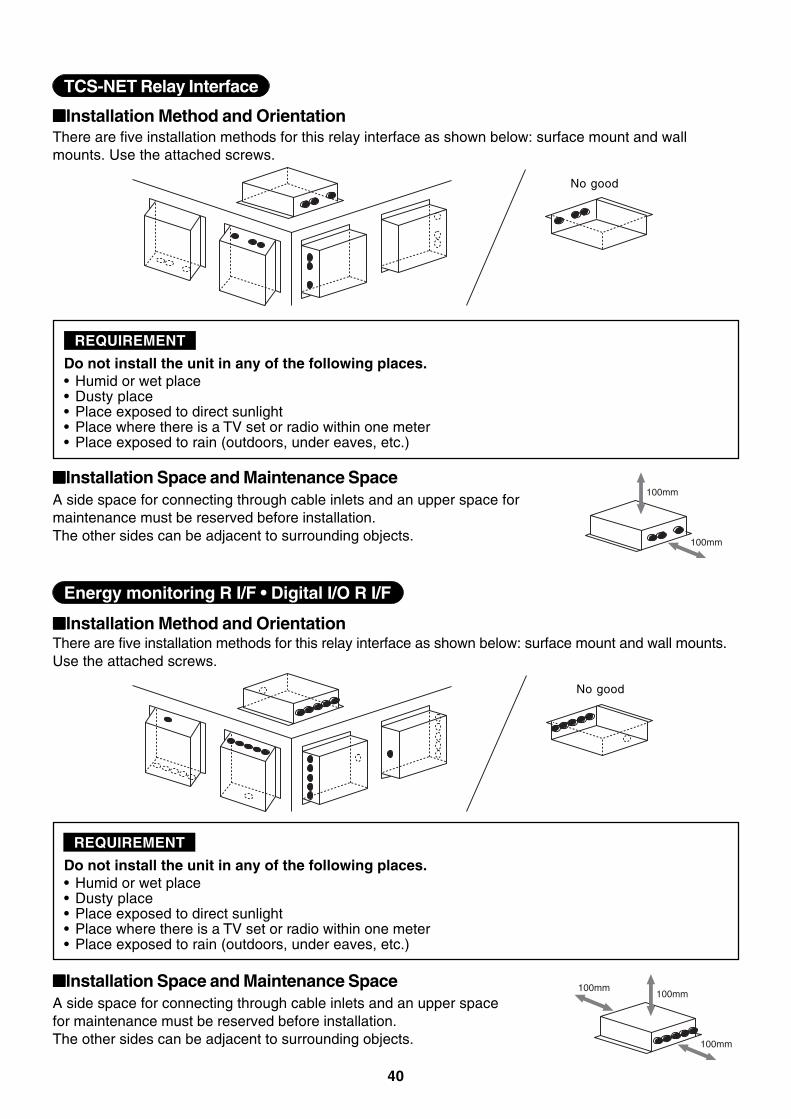
■■■■■Installation Method and Orientation
■■■■■Installation Space and Maintenance Space
There are five installation methods for this relay interface as shown below: surface mount and wallmounts. Use the attached screws.
Do not install the unit in any of the following places.• Humid or wet place• Dusty place• Place exposed to direct sunlight• Place where there is a TV set or radio within one meter• Place exposed to rain (outdoors, under eaves, etc.)
REQUIREMENT
A side space for connecting through cable inlets and an upper space formaintenance must be reserved before installation.The other sides can be adjacent to surrounding objects.
100mm
100mm
No good
TCS-NET Relay Interface
■■■■■Installation Method and OrientationThere are five installation methods for this relay interface as shown below: surface mount and wall mounts.Use the attached screws.
Do not install the unit in any of the following places.• Humid or wet place• Dusty place• Place exposed to direct sunlight• Place where there is a TV set or radio within one meter• Place exposed to rain (outdoors, under eaves, etc.)
REQUIREMENT
■■■■■Installation Space and Maintenance Space
No good
100mm
100mm
100mm
A side space for connecting through cable inlets and an upper spacefor maintenance must be reserved before installation.The other sides can be adjacent to surrounding objects.
Energy monitoring R I/F • Digital I/O R I/F
41
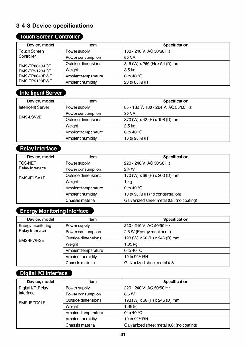
3-4-3 Device specifications
Touch Screen ControllerDevice, model
Touch ScreenController
BMS-TP0640ACEBMS-TP5120ACEBMS-TP0640PWEBMS-TP5120PWE
Specification
100 - 240 V, AC 50/60 Hz
50 VA
316 (W) x 256 (H) x 54 (D) mm
3.5 kg
0 to 40 °C
20 to 85%RH
Item
Power supply
Power consumption
Outside dimensions
Weight
Ambient temperature
Ambient humidity
Intelligent ServerDevice, model
Intelligent Server
BMS-LSV2E
Specification
85 - 132 V, 180 - 264 V, AC 50/60 Hz
30 VA
370 (W) x 42 (H) x 198 (D) mm
2.5 kg
0 to 40 °C
10 to 90%RH
Item
Power supply
Power consumption
Outside dimensions
Weight
Ambient temperature
Ambient humidity
Relay InterfaceDevice, model
TCS-NETRelay Interface
BMS-IFLSV1E
Specification
220 - 240 V, AC 50/60 Hz
2.4 W
170 (W) x 66 (H) x 200 (D) mm
1 kg
0 to 40 °C
10 to 90%RH (no condensation)
Galvanized sheet metal 0.8t (no coating)
Item
Power supply
Power consumption
Outside dimensions
Weight
Ambient temperature
Ambient humidity
Chassis material
Energy Monitoring Interface
Device, model
Energy monitoringRelay Interface
BMS-IFWH3E
Specification
220 - 240 V, AC 50/60 Hz
2.8 W (Energy monitoring)
193 (W) x 66 (H) x 246 (D) mm
1.65 kg
0 to 40 °C
10 to 90%RH
Galvanized sheet metal 0.8t
Item
Power supply
Power consumption
Outside dimensions
Weight
Ambient temperature
Ambient humidity
Chassis material
Digital I/O Interface
Device, model
Digital I/O RelayInterface
BMS-IFDD01E
Specification
220 - 240 V, AC 50/60 Hz
6.5 W
193 (W) x 66 (H) x 246 (D) mm
1.65 kg
0 to 40 °C
10 to 90%RH
Galvanized sheet metal 0.8t (no coating)
Item
Power supply
Power consumption
Outside dimensions
Weight
Ambient temperature
Ambient humidity
Chassis material
42
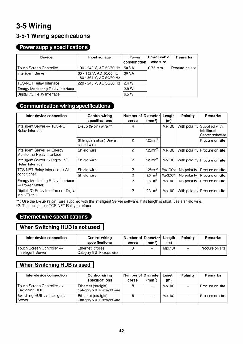
3-5 Wiring3-5-1 Wiring specifications
Touch Screen Controller
Intelligent Server
TCS-NET Relay Interface
Energy Monitoring Relay Interface
Digital I/O Relay Interface
Device Input voltage
Power supply specifications
Powerconsumption
50 VA
30 VA
2.4 W
2.8 W
6.5 W
Power cablewire size
Remarks
Intelligent Server ↔ TCS-NETRelay Interface
Intelligent Server ↔ EnergyMonitoring Relay Interface
Intelligent Server ↔ Digital I/ORelay Interface
TCS-NET Relay Interface ↔ Airconditioner
Energy Monitoring Relay Interface↔ Power Meter
Digital I/O Relay Interface ↔ DigitalInput/Output
Inter-device connection Control wiringspecifications
D-sub (9-pin) wire *1
(If length is short) Use ashield wire
Shield wire
Shield wire
Shield wire
Shield wire
Number ofcores
4
2
2
2
2
2
2
2
Diameter(mm2)
1.25 mm2
1.25 mm2
1.25 mm2
1.25 mm2
2.0 mm2
0.3 mm2
0.3 mm2
Length(m)
Max. 500
Max. 500
Max. 500
Max.1000*2
Max.2000*2
Max. 100
Max. 100
Polarity
With polarity
With polarity
With polarity
No polarity
No polarity
No polarity
With polarity
Remarks
Supplied withIntelligentServer software
Procure on site
Procure on site
Procure on site
Procure on site
Procure on site
Procure on site
Procure on site
*1: Use the D-sub (9 pin) wire supplied with the Intelligent Server software. If its length is short, use a shield wire.*2: Total length per TCS-NET Relay Interface
Touch Screen Controller ↔ Intelligent Server
Inter-device connection Control wiringspecifications
Ethernet (cross)Category 5 UTP cross wire
Number ofcores
8
Diameter(mm2)
–
Length(m)
Max. 100
Polarity
–
Remarks
Procure on site
When Switching HUB is not used
100 - 240 V, AC 50/60 Hz
85 - 132 V, AC 50/60 Hz180 - 264 V, AC 50/60 Hz
220 - 240 V, AC 50/60 Hz
0.75 mm2 Procure on site
Touch Screen Controller ↔ Switching HUB
Switching HUB ↔ IntelligentServer
Inter-device connection Control wiringspecifications
Ethernet (straight)Category 5 UTP straight wire
Ethernet (straight)Category 5 UTP straight wire
Number ofcores
8
8
Diameter(mm2)
–
–
Length(m)
Max. 100
Max. 100
Polarity
–
–
Remarks
Procure on site
Procure on site
When Switching HUB is used
Ethernet wire specifications
Communication wiring specifications
43
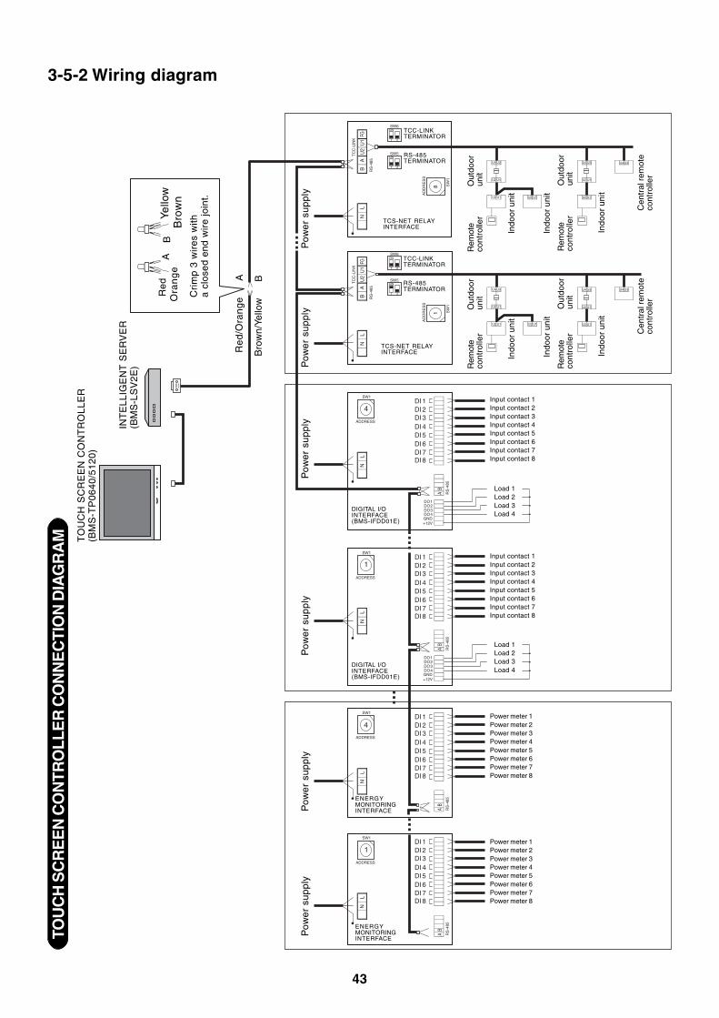
3-5-2 Wiring diagramTO
UC
H S
CR
EE
N C
ON
TRO
LLE
R C
ON
NE
CTI
ON
DIA
GR
AM
AB
FGU
1U
2
TC
C-L
INK
RS
-485
SW6ON
1 2
U2 U1
U4 U3
U2 U1
U4 U3 U4 U3
ON
1
1
2
SW5
SW6ON
1 2
ON
1 2
SW5
SW
1
AD
DR
ES
S
8 SW
1
AD
DR
ES
S
AB
LN
LN
LN
LN
LN
LN
FGU
1U
2
TC
C-L
INK
RS
-485
+12VGNDDO4DO3DO2DO1
DI 8DI 7DI 6DI 5DI 4DI 3DI 2DI 1
DI 8DI 7DI 6DI 5DI 4DI 3DI 2DI 1
DI 8DI 7DI 6DI 5DI 4DI 3DI 2DI 1
4
SW1
ADDRESS
1
SW1
ADDRESS
AB
RS
-485
AB
RS
-485
AB
RS
-485
AB
RS
-485
+12VGNDDO4DO3DO2DO1
DI 8DI 7DI 6DI 5DI 4DI 3DI 2DI 1
4
SW1
ADDRESS
1
SW1
ADDRESS
U2 U1 U2 U1 U2 U1
U2 U1
U4 U3
U2 U1
U4 U3 U4 U3
U2 U1 U2 U1 U2 U1
TO
UC
H S
CR
EE
N C
ON
TR
OL
LE
R(B
MS
-TP
06
40
/51
20
)
INT
ELL
IGE
NT
SE
RV
ER
(BM
S-L
SV
2E)
Red
Ora
ng
eYe
llow
Bro
wn
Cri
mp
3 w
ires
with
a cl
osed
end
wir
e jo
int.
Re
d/O
ran
ge
Bro
wn/
Yello
w
Pow
er s
uppl
y
DIGITAL I/OINTERFACE(BMS-IFDD01E)
DIGITAL I/OINTERFACE(BMS-IFDD01E)
ENERGYMONITORINGINTERFACE
ENERGYMONITORINGINTERFACE
Power meter 1Power meter 2Power meter 3Power meter 4Power meter 5Power meter 6Power meter 7Power meter 8
Power meter 1Power meter 2Power meter 3Power meter 4Power meter 5Power meter 6Power meter 7Power meter 8
Input contact 1Input contact 2Input contact 3Input contact 4Input contact 5Input contact 6Input contact 7Input contact 8
Input contact 1Input contact 2Input contact 3Input contact 4Input contact 5Input contact 6Input contact 7Input contact 8
Load 1Load 2Load 3Load 4
Load 1Load 2Load 3Load 4
TCS-NET RELAYINTERFACE
TCS-NET RELAYINTERFACE
TCC-LINKTERMINATOR
RS-485TERMINATOR
TCC-LINKTERMINATOR
RS-485TERMINATOR
Out
door
unit
Indo
or u
nit
Indo
or u
nit
Rem
ote
cont
rolle
r
Out
door
unit
Indo
or u
nit
Rem
ote
cont
rolle
r
Cen
tral
rem
ote
cont
rolle
r
Out
door
unit
Indo
or u
nit
Indo
or u
nit
Rem
ote
cont
rolle
r
Out
door
unit
Indo
or u
nit
Rem
ote
cont
rolle
r Cen
tral
rem
ote
cont
rolle
r
A B
AB
Pow
er s
uppl
yP
ower
sup
ply
Pow
er s
uppl
yP
ower
sup
ply
Pow
er s
uppl
y
44
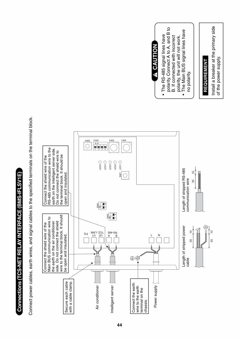
Con
nect
ions
(TC
S-N
ET
RE
LAY
INTE
RFA
CE
(BM
S-IF
LSV
1E)
Con
nect
pow
er c
able
s, e
arth
wire
s, a
nd s
igna
l cab
les
to th
e sp
ecifi
ed te
rmin
als
on th
e te
rmin
al b
lock
.
•T
he R
S-4
85 s
igna
l lin
es h
ave
pola
rity
. Con
nect
A to
A, a
nd B
toB
. If c
onne
cted
with
inco
rrec
tpo
larit
y, th
e un
it w
ill n
ot w
ork.
•T
he M
ain
BU
S s
igna
l lin
es h
ave
no p
olar
ity. C
AU
TIO
N1
O
SW
6
N
ON
ON
LED
5
3
12
12
LED
4
4
SW
5O
NO
NLE
D3
12
12
LED
2
SW
7LE
D1
U2U1TCC-LINK
BARS-485
2
SW1SW2SW3SW4
FG
3510
3510
L N
5510
L N
Sec
ure
each
cab
lew
ith a
cab
le c
lam
p.
Con
nect
the
shi
eld
wir
e of
the
Mai
n B
US
com
mun
icat
ion
wir
e to
the
eart
h on
the
air
con
ditio
ner
side
. D
o no
t co
nnec
t th
e sh
ield
wire
to th
e te
rmin
al b
lock
. It s
houl
dbe
ope
n an
d in
sula
ted.
Con
nect
the
shi
eld
wir
e of
the
RS
-485
com
mun
icat
ion
wir
e to
the
eart
h on
the
Int
ellig
ent
serv
er s
ide.
Do
not
conn
ect
the
shie
ld w
ire
toth
e te
rmin
al b
lock
. It
shou
ld b
eop
en a
nd in
sula
ted.
Air
con
ditio
ner
Inte
llige
nt s
erve
r
Pow
er s
uppl
y
Leng
th o
f st
ripp
ed p
ower
cab
leLe
ngth
of
stri
pped
RS
-485
com
mu
nic
atio
n w
ire
Inst
all a
bre
aker
at t
he p
rimar
y si
deof
the
pow
er s
uppl
y.
RE
QU
IRE
ME
NT
Con
nect
the
ear
thw
ire
to t
he e
arth
term
inal
on
the
chas
sis.
45
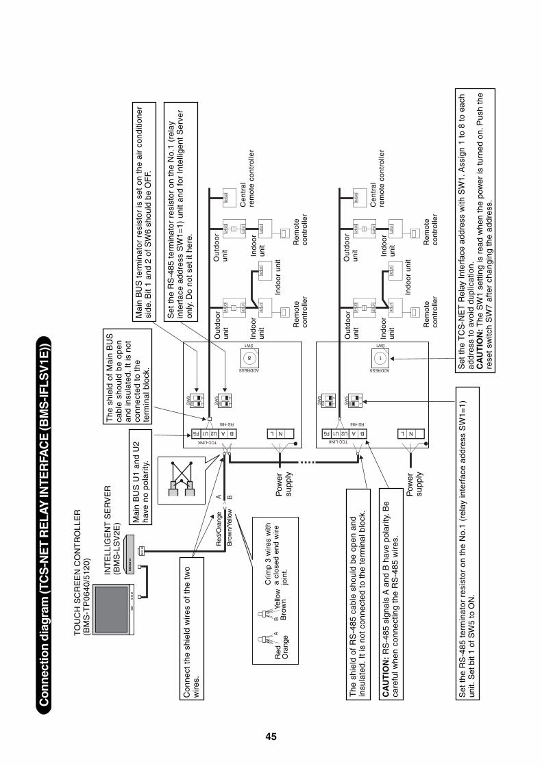
Con
nect
ion
diag
ram
(TC
S-N
ET
RE
LAY
INTE
RFA
CE
(BM
S-IF
LSV
1E))
A
A BFG U1 U2
TCC-LINKTCC-LINK
RS-485
SW
6O
N 12
U2
U1
U4
U3
U2
U1
U4
U3
U4
U3
ON 1
8
2
SW
5
SW1
ADDRESS
A BFG U1 U2
RS-485
SW
6O
N 12
ON 1
2
SW
5
B
1
SW1
ADDRESSU
2U
1U
2U
1U
2U
1
U2
U1
U4
U3
U2
U1
U4
U3
U4
U3
U2
U1
U2
U1
U2
U1
AB
L NL N
Con
nect
the
shi
eld
wir
es o
f th
e tw
ow
ires.
Mai
n B
US
U1
and
U2
have
no
pola
rity
.
The
shi
eld
of M
ain
BU
Sca
ble
sh
ou
ld b
e o
pe
nan
d in
sula
ted.
It is
not
conn
ecte
d to
the
term
inal
blo
ck.
Mai
n B
US
ter
min
ator
res
isto
r is
set
on
the
air
cond
ition
ersi
de. B
it 1
and
2 of
SW
6 sh
ould
be
OF
F.
Set
the
RS
-485
ter
min
ator
res
isto
r on
the
No.
1 (r
elay
inte
rfac
e ad
dres
s S
W1=
1) u
nit
and
for
Inte
llige
nt S
erve
ron
ly. D
o no
t set
it h
ere.
The
shi
eld
of R
S-4
85 c
able
sho
uld
be o
pen
and
insu
late
d. I
t is
not
con
nect
ed t
o th
e te
rmin
al b
lock
.
CA
UT
ION
: R
S-4
85 s
igna
ls A
and
B h
ave
pola
rity
. Be
care
ful w
hen
conn
ectin
g th
e R
S-4
85 w
ires
.
TO
UC
H S
CR
EE
N C
ON
TR
OLL
ER
(BM
S-T
P06
40/5
120)
INT
ELL
IGE
NT
SE
RV
ER
(BM
S-L
SV
2E)
Red
Ora
nge
Yello
wB
row
n
Cri
mp
3 w
ires
with
a cl
osed
end
wir
ejo
int.
Red
/Ora
nge
Bro
wn/
Yello
w
Pow
ersu
pply
Ou
tdo
or
unit R
em
ote
cont
rolle
rIndo
or u
nit
Ind
oo
run
it
Ou
tdo
or
unit
Re
mo
teco
ntro
ller
Ind
oo
run
it
Ce
ntr
al
rem
ote
cont
rolle
r
Set
the
RS
-485
ter
min
ator
res
isto
r on
the
No.
1 (r
elay
inte
rfac
e ad
dres
s S
W1=
1)un
it. S
et b
it 1
of S
W5
to O
N.
Set
the
TC
S-N
ET
Rel
ay I
nter
face
add
ress
with
SW
1. A
ssig
n 1
to 8
to
each
addr
ess
to a
void
dup
licat
ion.
CA
UT
ION
: The
SW
1 se
tting
is r
ead
whe
n th
e po
wer
is t
urne
d on
. Pus
h th
ere
set
switc
h S
W7
afte
r ch
angi
ng t
he a
ddre
ss.
Ou
tdo
or
unit R
em
ote
cont
rolle
rIndo
or u
nit
Ind
oo
run
it
Ou
tdo
or
unit
Re
mo
teco
ntro
ller
Ind
oo
run
it
Ce
ntr
al
rem
ote
cont
rolle
r
Pow
ersu
pply
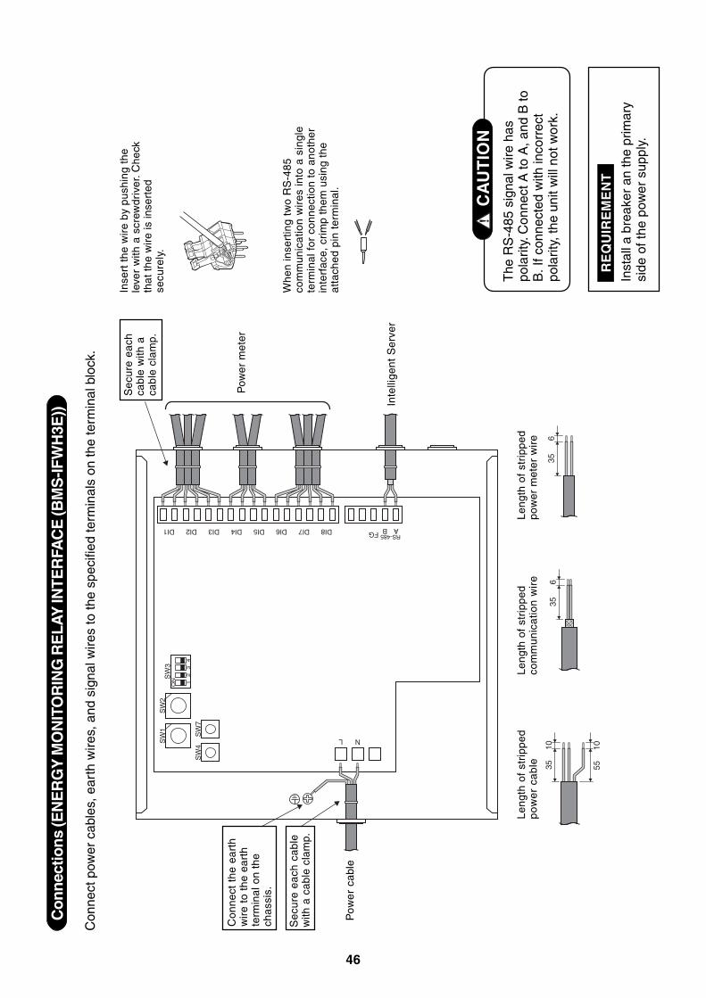
46
Con
nect
ions
(EN
ER
GY
MO
NIT
OR
ING
RE
LAY
INTE
RFA
CE
(BM
S-IF
WH
3E))
Con
nect
pow
er c
able
s, e
arth
wire
s, a
nd s
igna
l wire
s to
the
spec
ified
term
inal
s on
the
term
inal
blo
ck.
The
RS
-485
sig
nal w
ire h
aspo
larit
y. C
onne
ct A
to A
, and
B to
B. I
f con
nect
ed w
ith in
corr
ect
pola
rity,
the
unit
will
not
wor
k.
CA
UT
ION
Inst
all a
bre
aker
an
the
prim
ary
side
of t
he p
ower
sup
ply.
RE
QU
IRE
ME
NT
3535
356
610
5510
ON
SW
1
DI1 DI2 DI3 DI4 DI5 DI6 DI7 DI8 FG B A
SW
2S
W3
SW
4S
W7
12
34
N
RS-485
L
Sec
ure
each
cab
lew
ith a
cab
le c
lam
p.
Pow
er
cabl
e
Sec
ure
each
cabl
e w
ith a
cabl
e cl
amp.
Pow
er m
eter
Inte
llige
nt S
erve
r
Leng
th o
f st
ripp
edp
ow
er
cab
leLe
ngth
of
stri
pped
com
mu
nic
atio
n w
ire
Leng
th o
f st
ripp
edpo
wer
met
er w
ire
Inse
rt t
he w
ire
by p
ushi
ng t
hele
ver
with
a s
crew
driv
er. C
heck
that
the
wir
e is
inse
rted
secu
rely
.
Whe
n in
sert
ing
two
RS
-485
com
mun
icat
ion
wir
es in
to a
sin
gle
term
inal
for
con
nect
ion
to a
noth
erin
terf
ace,
cri
mp
them
usi
ng t
heat
tach
ed p
in t
erm
inal
.
Con
nect
the
ear
thw
ire
to t
he e
arth
term
inal
on
the
chas
sis.
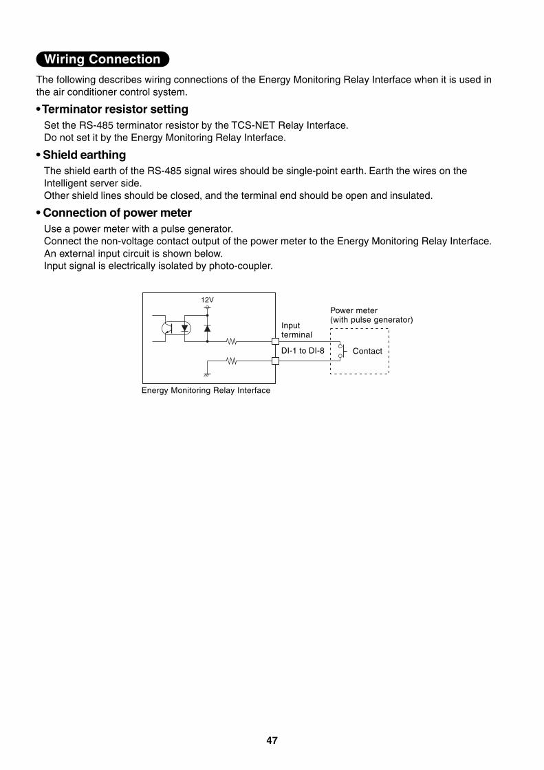
47
The following describes wiring connections of the Energy Monitoring Relay Interface when it is used inthe air conditioner control system.
• Terminator resistor settingSet the RS-485 terminator resistor by the TCS-NET Relay Interface.Do not set it by the Energy Monitoring Relay Interface.
• Shield earthingThe shield earth of the RS-485 signal wires should be single-point earth. Earth the wires on theIntelligent server side.Other shield lines should be closed, and the terminal end should be open and insulated.
• Connection of power meterUse a power meter with a pulse generator.Connect the non-voltage contact output of the power meter to the Energy Monitoring Relay Interface.An external input circuit is shown below.Input signal is electrically isolated by photo-coupler.
12V
Wiring Connection
Energy Monitoring Relay Interface
Inputterminal
Power meter(with pulse generator)
ContactDI-1 to DI-8
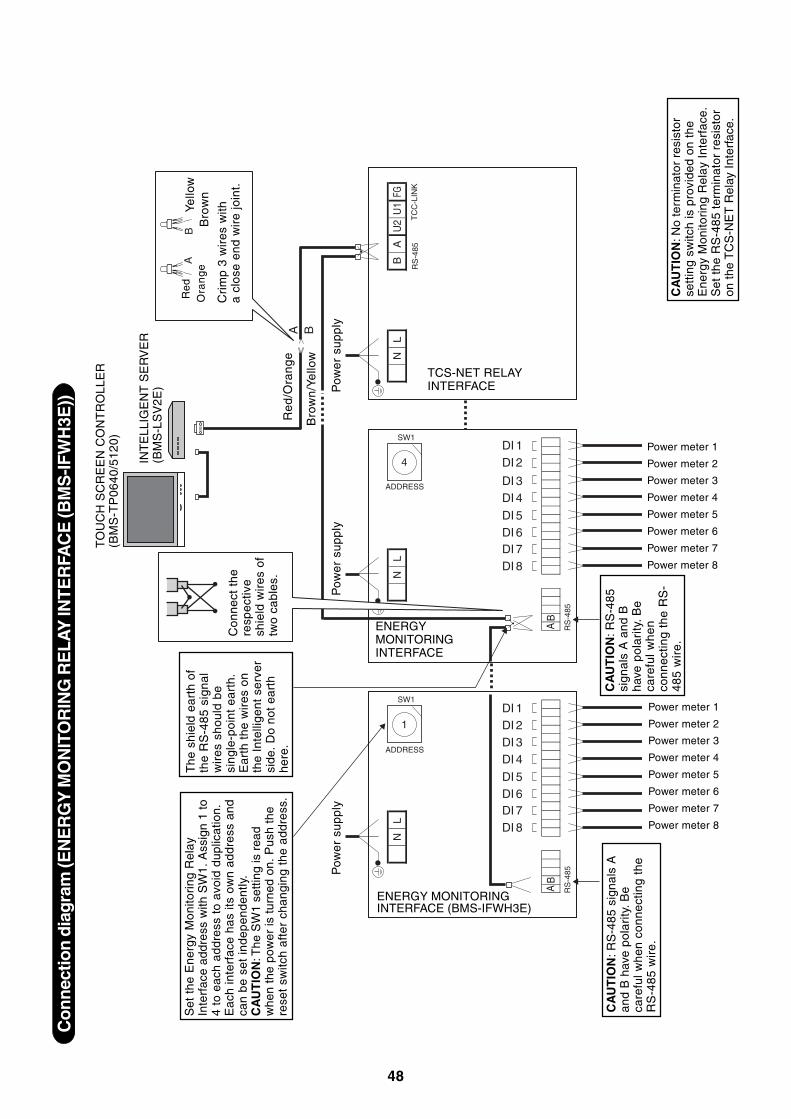
48
Con
nect
ion
diag
ram
(EN
ER
GY
MO
NIT
OR
ING
RE
LAY
INTE
RFA
CE
(BM
S-IF
WH
3E))
A B
AB
AB
LN
FGU
1U
2 TC
C-L
INK
RS
-485
LN
LN
DI 8DI 7DI 6DI 5
DI 4DI 3DI 2DI 1
DI 2DI 1
DI 8DI 7DI 6DI 5
DI 4DI 3
1
SW1
SW1
ADDRESS
4
ADDRESS
AB
RS
-485
AB
RS
-485
Set
the
Ene
rgy
Mon
itori
ng R
elay
Inte
rfac
e ad
dres
s w
ith S
W1.
Ass
ign
1 to
4 to
eac
h ad
dres
s to
avo
id d
uplic
atio
n.E
ach
inte
rfac
e ha
s its
ow
n ad
dres
s an
dca
n be
set
inde
pend
ently
.C
AU
TIO
N: T
he S
W1
setti
ng is
rea
dw
hen
the
pow
er is
tur
ned
on.
Pus
h th
ere
set
switc
h af
ter
chan
ging
the
add
ress
.
Con
nect
the
resp
ectiv
esh
ield
wir
es o
ftw
o ca
bles
.
The
shi
eld
eart
h of
the
RS
-485
sig
nal
wir
es s
houl
d be
sing
le-p
oint
ear
th.
Ear
th t
he w
ires
on
the
Inte
llige
nt s
erve
rsi
de.
Do
not
eart
hhe
re.
CA
UT
ION
: RS
-485
sign
als
A a
nd B
have
pol
arity
. Be
care
ful w
hen
conn
ectin
g th
e R
S-
485
wir
e.C
AU
TIO
N: N
o te
rmin
ator
res
isto
rse
ttin
g sw
itch
is p
rovi
ded
on t
heE
nerg
y M
onito
ring
Rel
ay I
nter
face
.S
et t
he R
S-4
85 t
erm
inat
or r
esis
tor
on t
he T
CS
-NE
T R
elay
Int
erfa
ce.
TO
UC
H S
CR
EE
N C
ON
TR
OLL
ER
(BM
S-T
P06
40/5
120)
INT
ELL
IGE
NT
SE
RV
ER
(BM
S-L
SV
2E)
Re
d/O
ran
ge
Bro
wn
/Ye
llow
Pow
er s
uppl
y
Red
Ora
ng
eYe
llow
Bro
wn
Cri
mp
3 w
ires
with
a cl
ose
end
wir
e jo
int.
TCS-NET RELAYINTERFACE
ENERGYMONITORINGINTERFACE
ENERGY MONITORINGINTERFACE (BMS-IFWH3E)
CA
UT
ION
: RS
-485
sig
nals
Aan
d B
hav
e po
lari
ty. B
eca
refu
l whe
n co
nnec
ting
the
RS
-485
wir
e.
Power meter 1
Power meter 2
Power meter 3
Power meter 4
Power meter 5
Power meter 6
Power meter 7
Power meter 8
Power meter 1
Power meter 2
Power meter 3
Power meter 4
Power meter 5
Power meter 6
Power meter 7
Power meter 8
Pow
er s
uppl
yP
ower
sup
ply
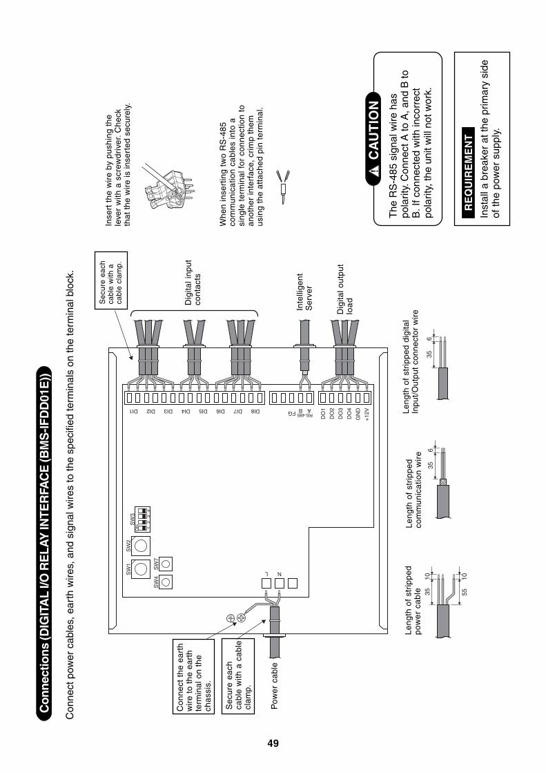
49
Con
nect
ions
(DIG
ITA
L I/O
RE
LAY
INTE
RFA
CE
(BM
S-IF
DD
01E
))
Con
nect
pow
er c
able
s, e
arth
wire
s, a
nd s
igna
l wire
s to
the
spec
ified
term
inal
s on
the
term
inal
blo
ck.
The
RS
-485
sig
nal w
ire h
aspo
larit
y. C
onne
ct A
to A
, and
B to
B. I
f con
nect
ed w
ith in
corr
ect
pola
rity,
the
unit
will
not
wor
k.
CA
UT
ION
Inst
all a
bre
aker
at t
he p
rimar
y si
deof
the
pow
er s
uppl
y.
RE
QU
IRE
ME
NT
3535
356
610
5510
ON
SW
1
DI1 DI2 DI3 DI4 DI5 DI6 DI7 DI8 FG B
DO
1
DO
2
DO
3
DO
4
GN
D
+12
VA
SW
2S
W3
SW
4S
W7
12
34
N
RS-485
L
Sec
ure
each
cabl
e w
ith a
cab
lecl
amp.
Pow
er
cabl
e
Se
cure
ea
chca
ble
with
aca
ble
clam
p.
Dig
ital i
nput
cont
acts
Inte
llige
ntS
erve
r
Dig
ital o
utpu
tlo
ad
Leng
th o
f st
ripp
edp
ow
er
cab
leLe
ngth
of
stri
pped
com
mu
nic
atio
n w
ire
Leng
th o
f st
ripp
ed d
igita
lIn
put/
Out
put
conn
ecto
r w
ire
Inse
rt t
he w
ire
by p
ushi
ng t
hele
ver
with
a s
crew
driv
er. C
heck
that
the
wire
is in
sert
ed s
ecur
ely.
Whe
n in
sert
ing
two
RS
-485
com
mun
icat
ion
cabl
es in
to a
sing
le t
erm
inal
for
con
nect
ion
toan
othe
r in
terf
ace,
cri
mp
them
usin
g th
e at
tach
ed p
in t
erm
inal
.
Con
nect
the
ear
thw
ire
to t
he e
arth
term
inal
on
the
chas
sis.
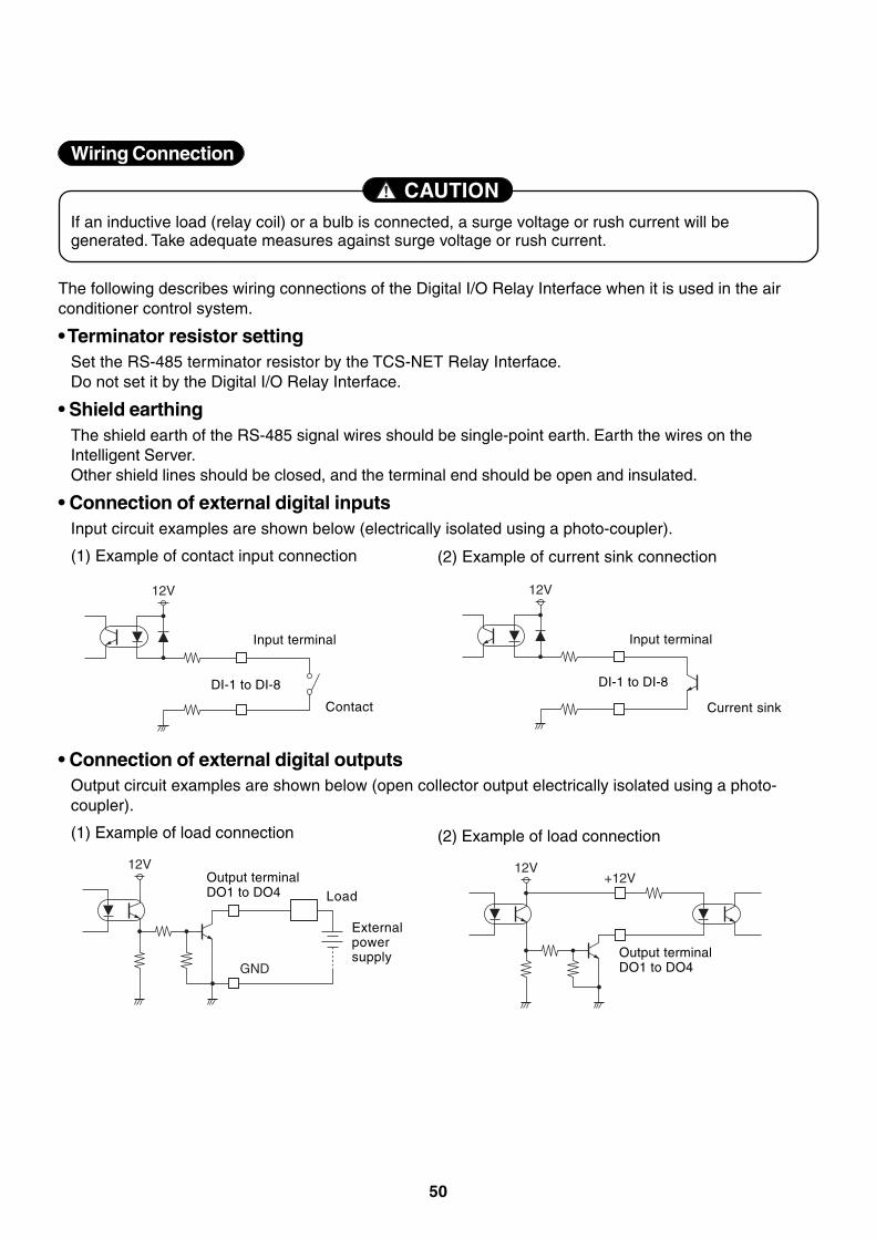
50
If an inductive load (relay coil) or a bulb is connected, a surge voltage or rush current will begenerated. Take adequate measures against surge voltage or rush current.
CAUTION
Wiring Connection
The following describes wiring connections of the Digital I/O Relay Interface when it is used in the airconditioner control system.
• Terminator resistor settingSet the RS-485 terminator resistor by the TCS-NET Relay Interface.Do not set it by the Digital I/O Relay Interface.
• Shield earthingThe shield earth of the RS-485 signal wires should be single-point earth. Earth the wires on theIntelligent Server.Other shield lines should be closed, and the terminal end should be open and insulated.
• Connection of external digital inputsInput circuit examples are shown below (electrically isolated using a photo-coupler).
(1) Example of contact input connection (2) Example of current sink connection
12V 12V
Contact
Input terminal
DI-1 to DI-8
Current sink
Input terminal
DI-1 to DI-8
• Connection of external digital outputsOutput circuit examples are shown below (open collector output electrically isolated using a photo-coupler).
(1) Example of load connection (2) Example of load connection
12V
GND
12V+12VOutput terminal
DO1 to DO4 Load
Externalpowersupply Output terminal
DO1 to DO4
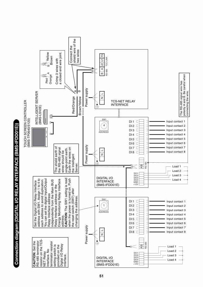
51
Co
nnec
tion
dia
gram
(DIG
ITA
L I/O
RE
LA
Y IN
TER
FAC
E (B
MS
-IFD
D01
E))
A B
AB
AB
FGU
1U
2
TC
C-L
INK
RS
-485
4
SW1
ADDRESS
AB
RS
-485
AB
RS
-485
DI 8
+12VGNDDO4DO3DO2DO1
+12VGNDDO4DO3DO2DO1
DI 7
DI 6DI 5
DI 4
DI 3DI 2DI 1
DI 8DI 7
DI 6DI 5
DI 4
DI 3DI 2DI 1
1
SW1
ADDRESS
LN
LN
LN
The
shi
eld
eart
h of
the
RS
-485
sig
nal
wir
es s
houl
d be
sing
le-p
oint
ear
th.
Ear
th t
he w
ires
on
the
Inte
llige
ntS
erve
r.
Set
the
Dig
ital I
/O R
elay
Inte
rfac
ead
dres
s w
ith S
W1.
Ass
ign
1 to
4 to
each
add
ress
to
avoi
d du
plic
atio
n.Yo
u ca
n se
t th
e di
gita
l Inp
ut/O
utpu
tR
elay
Int
erfa
ce a
ddre
ssin
depe
nden
tly f
rom
the
Mai
n B
US
Rel
ay I
nter
face
add
ress
or
the
Ene
rgy
Mon
itori
ng R
elay
Int
erfa
cea
dd
ress
.C
AU
TIO
N: T
he S
W1
setti
ng is
rea
dw
hen
the
pow
er is
tur
ned
on.
Pus
hth
e re
set s
witc
h (S
W7)
afte
rch
angi
ng t
he a
ddre
ss.
DIGITAL I/OINTERFACE(BMS-IFDD01E)
DIGITAL I/OINTERFACE(BMS-IFDD01E)
TCS-NET RELAYINTERFACE
CA
UT
ION
: S
et th
eR
S-4
85 t
erm
inat
orre
sist
or o
n th
e T
CS
-N
ET
Rel
ayIn
terf
ace.
No
term
inat
or r
esis
tor
sett
ing
switc
h is
prov
ided
on
the
Dig
ital I
/O R
elay
Inte
rfac
e.
The
RS
-485
sig
nal w
ire
has
pola
rity
A a
nd B
. B
e ca
refu
l whe
nco
nnec
ting
the
wir
e.
TO
UC
H S
CR
EE
N C
ON
TR
OLL
ER
(BM
S-T
P06
40/5
120)
INT
ELL
IGE
NT
SE
RV
ER
(BM
S-L
SV
2E)
Re
d/O
ran
ge
Bro
wn
/Ye
llow
Pow
er s
uppl
y
Input contact 1
Input contact 2
Input contact 3
Input contact 4
Input contact 5
Input contact 6
Input contact 7
Input contact 8
Load 1
Load 2
Load 3
Load 4
Input contact 1
Input contact 2
Input contact 3
Input contact 4
Input contact 5
Input contact 6
Input contact 7
Input contact 8
Load 1
Load 2
Load 3
Load 4
Red
Ora
ng
eYe
llow
Bro
wn
Cri
mp
3 w
ires
with
a cl
osed
end
wir
e jo
int.
Con
nect
the
shie
ld w
ire
of t
hetw
o w
ires
Pow
er s
uppl
yP
ower
sup
ply
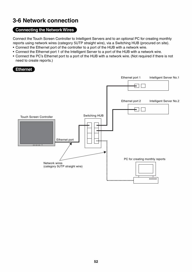
52
3-6 Network connection
Connecting the Network Wires
Connect the Touch Screen Controller to Intelligent Servers and to an optional PC for creating monthlyreports using network wires (category 5UTP straight wire), via a Switching HUB (procured on site).• Connect the Ethernet port of the controller to a port of the HUB with a network wire.• Connect the Ethernet port 1 of the Intelligent Server to a port of the HUB with a network wire.• Connect the PC’s Ethernet port to a port of the HUB with a network wire. (Not required if there is not
need to create reports.)
Ethernet
PC for creating monthly reports
Touch Screen Controller Switching HUB
Intelligent Server No.1
Intelligent Server No.2
Network wires(category 5UTP straight wire)
Ethernet port 1
Ethernet port 2
Ethernet port
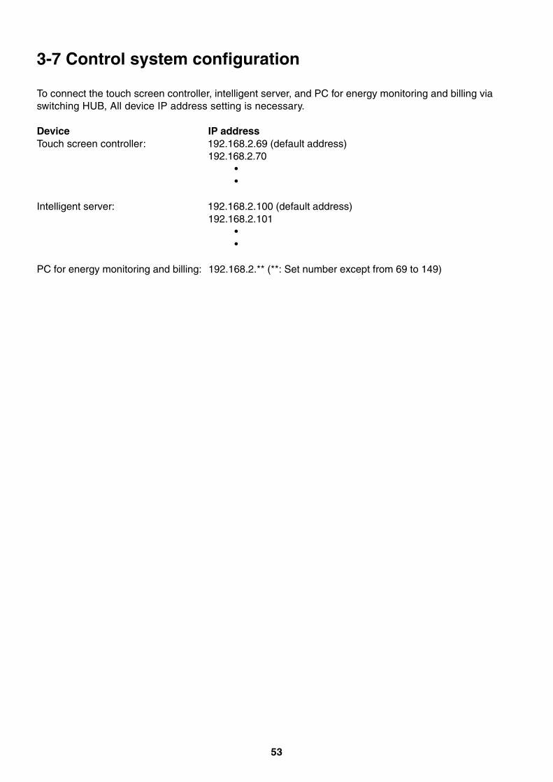
53
3-7 Control system configuration
To connect the touch screen controller, intelligent server, and PC for energy monitoring and billing viaswitching HUB, All device IP address setting is necessary.
Device IP addressTouch screen controller: 192.168.2.69 (default address)
192.168.2.70••
Intelligent server: 192.168.2.100 (default address)192.168.2.101
••
PC for energy monitoring and billing: 192.168.2.** (**: Set number except from 69 to 149)

54
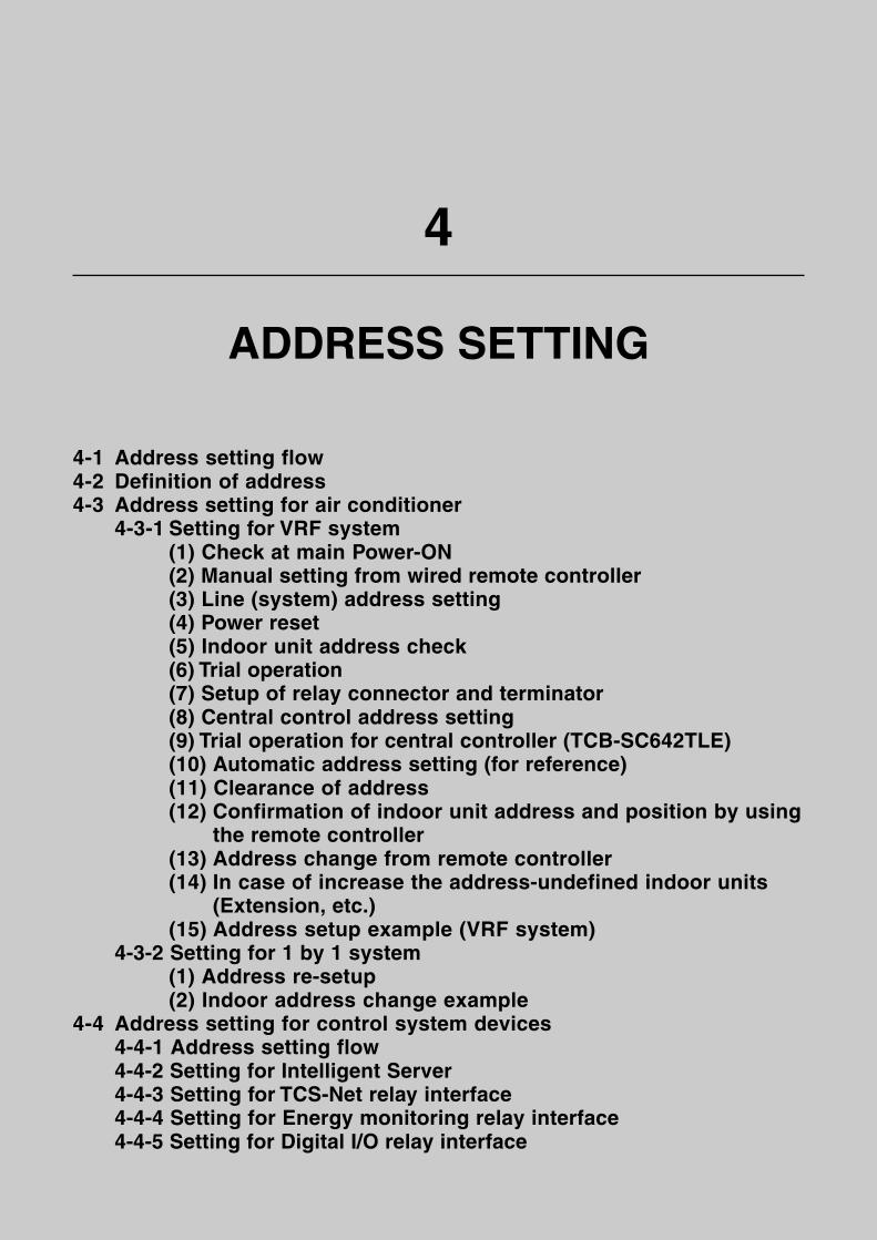
55
4
ADDRESS SETTING
4-1 Address setting flow4-2 Definition of address4-3 Address setting for air conditioner
4-3-1 Setting for VRF system(1) Check at main Power-ON(2) Manual setting from wired remote controller(3) Line (system) address setting(4) Power reset(5) Indoor unit address check(6) Trial operation(7) Setup of relay connector and terminator(8) Central control address setting(9) Trial operation for central controller (TCB-SC642TLE)(10) Automatic address setting (for reference)(11) Clearance of address(12) Confirmation of indoor unit address and position by using
the remote controller(13) Address change from remote controller(14) In case of increase the address-undefined indoor units
(Extension, etc.)(15) Address setup example (VRF system)
4-3-2 Setting for 1 by 1 system(1) Address re-setup(2) Indoor address change example
4-4 Address setting for control system devices4-4-1 Address setting flow4-4-2 Setting for Intelligent Server4-4-3 Setting for TCS-Net relay interface4-4-4 Setting for Energy monitoring relay interface4-4-5 Setting for Digital I/O relay interface
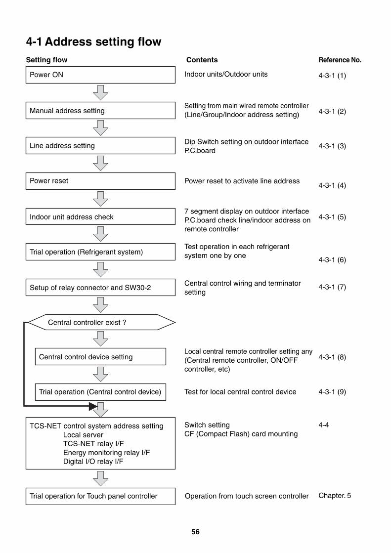
56
4-1 Address setting flowSetting flow
Power ON
Contents Reference No.
Manual address setting
Line address setting
Indoor units/Outdoor units
Setting from main wired remote controller(Line/Group/Indoor address setting)
Dip Switch setting on outdoor interfaceP.C.board
Power reset to activate line address
7 segment display on outdoor interfaceP.C.board check line/indoor address onremote controller
Test operation in each refrigerantsystem one by one
4-3-1 (1)
Power reset
Indoor unit address check
Trial operation (Refrigerant system)
Setup of relay connector and SW30-2
Central controller exist ?
Central control device setting
Trial operation (Central control device)
TCS-NET control system address settingLocal serverTCS-NET relay I/FEnergy monitoring relay I/FDigital I/O relay I/F
Central control wiring and terminatorsetting
Local central remote controller setting any(Central remote controller, ON/OFFcontroller, etc)
Test for local central control device
Switch settingCF (Compact Flash) card mounting
4-3-1 (2)
4-3-1 (3)
4-3-1 (4)
4-3-1 (5)
4-3-1 (6)
4-3-1 (7)
4-3-1 (8)
4-3-1 (9)
4-4
Chapter. 5Trial operation for Touch panel controller Operation from touch screen controller
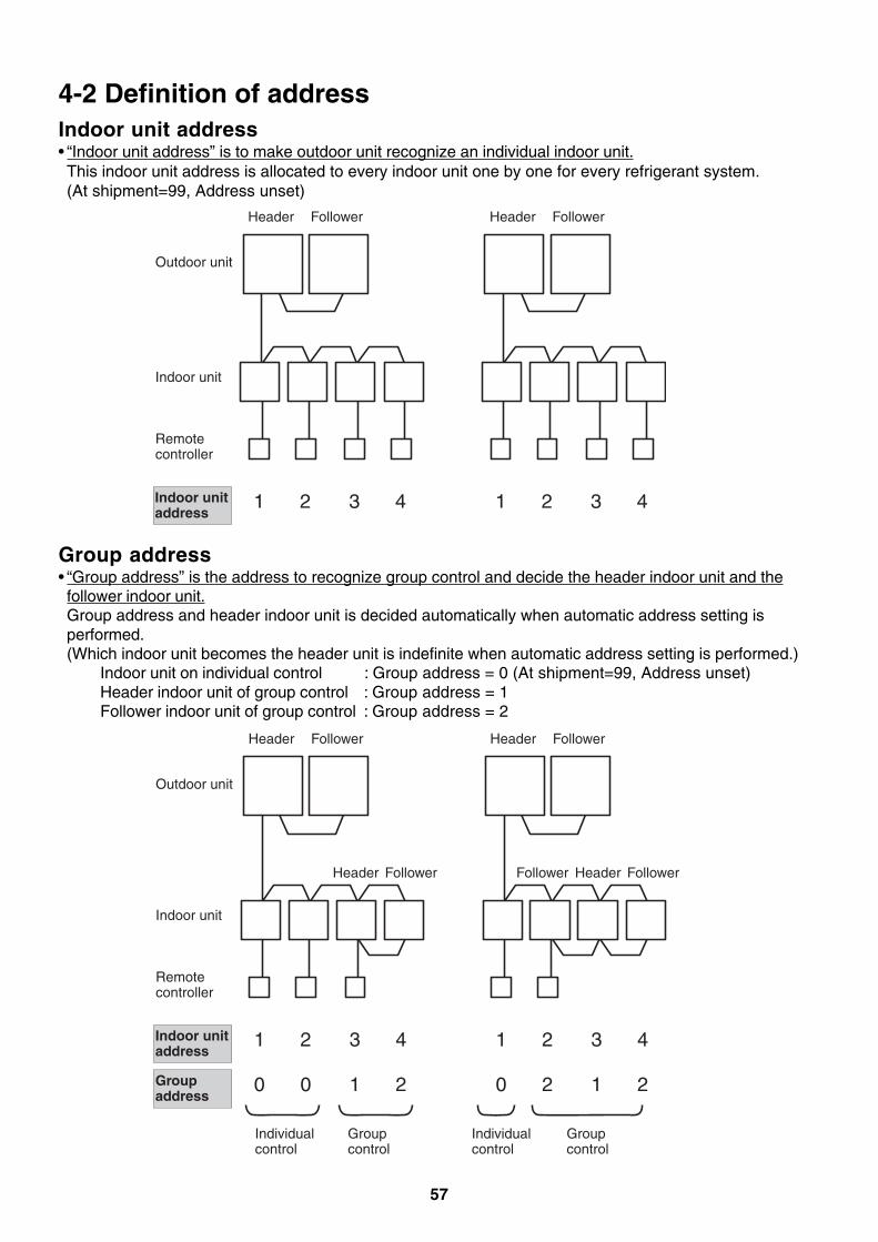
57
4-2 Definition of addressIndoor unit address• “Indoor unit address” is to make outdoor unit recognize an individual indoor unit.This indoor unit address is allocated to every indoor unit one by one for every refrigerant system.(At shipment=99, Address unset)
Group address• “Group address” is the address to recognize group control and decide the header indoor unit and thefollower indoor unit.Group address and header indoor unit is decided automatically when automatic address setting isperformed.(Which indoor unit becomes the header unit is indefinite when automatic address setting is performed.)
Indoor unit on individual control : Group address = 0 (At shipment=99, Address unset)Header indoor unit of group control : Group address = 1Follower indoor unit of group control : Group address = 2
Indoor unit address
Header
Outdoor unit
Indoor unit
Remote controller
Follower
1 2 3 4
Header Follower
1 2 3 4
Indoor unit address
Header
Outdoor unit
Indoor unit
Remote controller
Follower
HeaderFollower FollowerHeader Follower
1 2 3 4
Header Follower
1 2 3 4
Group address
0 0 1 2 0 2 1 2
Individual control
Group control
Individual control
Group control

58
Line address (System address)• “Line address” is the address with which line (refrigerant system) indoor units are connected.This line address is set by switch setting on interface P.C. board of the header outdoor unit.
Header
Dip Switch setting
Central control device
Outdoor unit
Indoor unit
(At shipment=99, Address unset)
Remote controller
Follower
1 1
1
1 1Line address
Header Follower
2 2
2
2 2
Line address ( Outdoor)
Line 1 (Refrigerant system 1)
Line 2 (Refrigerant system 2)
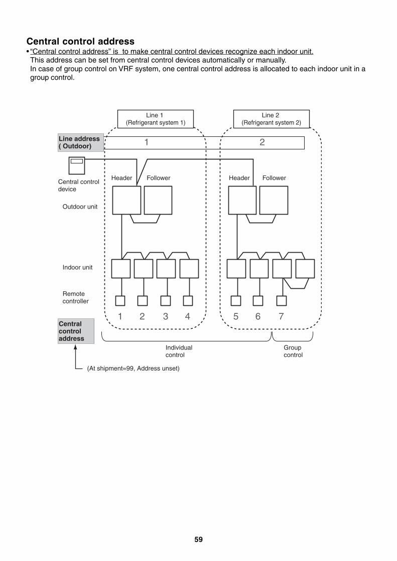
59
Central control address• “Central control address” is to make central control devices recognize each indoor unit.This address can be set from central control devices automatically or manually.In case of group control on VRF system, one central control address is allocated to each indoor unit in agroup control.
HeaderCentral controldevice
Outdoor unit
Indoor unit
Remote controller
Follower
1 2
1
3 4Central control address
Header Follower
5 6
2
7
Line address ( Outdoor)
Line 1 (Refrigerant system 1)
Line 2 (Refrigerant system 2)
Individual control
Group control
(At shipment=99, Address unset)
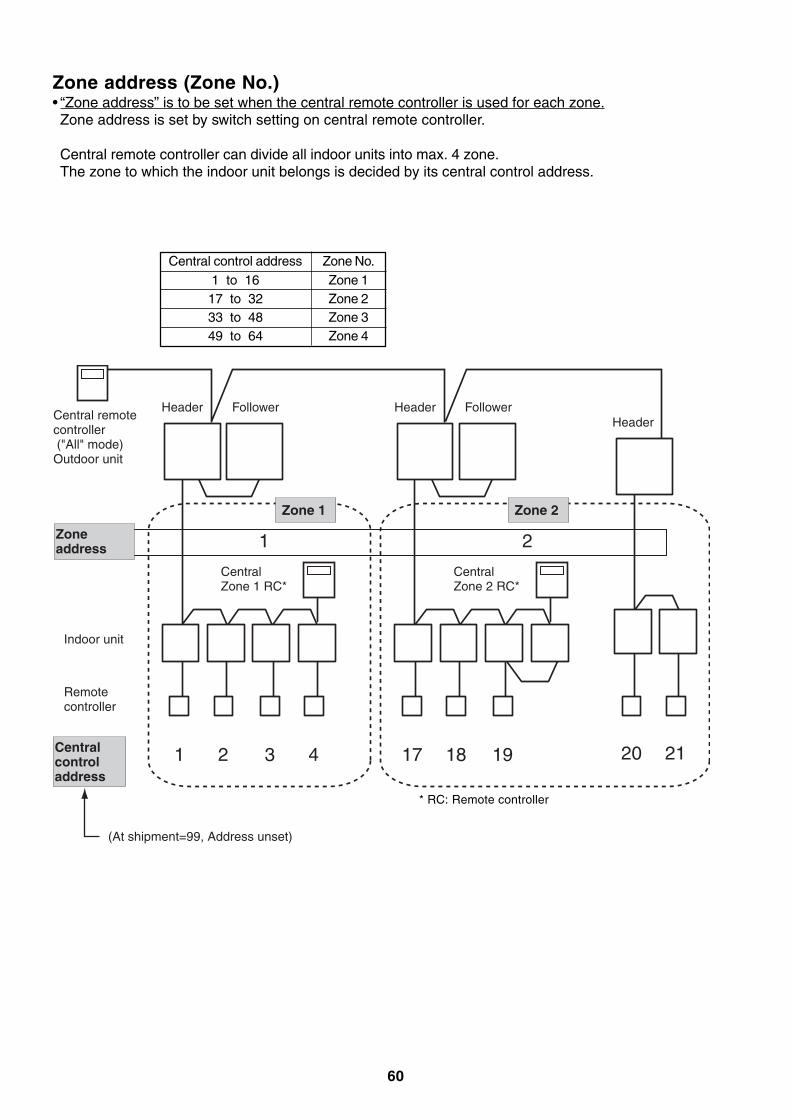
60
Zone address (Zone No.)• “Zone address” is to be set when the central remote controller is used for each zone.Zone address is set by switch setting on central remote controller.
Central remote controller can divide all indoor units into max. 4 zone.The zone to which the indoor unit belongs is decided by its central control address.
Central control address1 to 1617 to 3233 to 4849 to 64
Zone 1Zone 2Zone 3Zone 4
HeaderCentral remote controller ("All" mode)Outdoor unit
Indoor unit
Remote controller
Follower
1 2 3 4
Header
20 21
Zone 1
Central Zone 1 RC*
Header Follower
17 18 19
Zone 2
Central Zone 2 RC*
1 2Zone address
Central control address
(At shipment=99, Address unset)
Zone No.
* RC: Remote controller
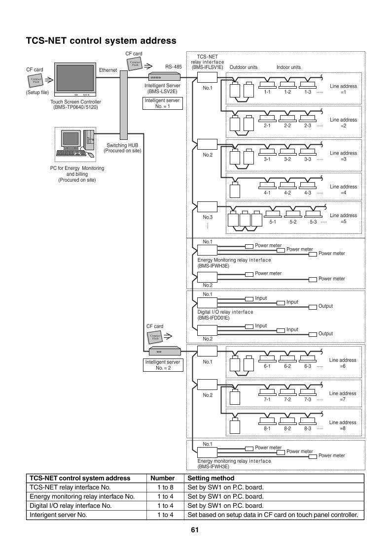
61
TCS-NET control system address
CompactFlash
CompactFlash
CompactFlash
CF card
TCS-NETrelay interface(BMS-IFLSV1E)
No.11-1 1-2 1-3 .....
.....
.....
.....
.....
.....
2-1 2-2 2-3
3-1 3-2 3-3
4-1 4-2 4-3
5-1 5-2 5-3
No.2
No.1
No.2
No.3
Outdoor units Indoor units
Intelligent server No. = 1
EthernetCF card
CF card
Touch Screen Controller(BMS-TP0640/5120)
Switching HUB(Procured on site)
PC for Energy Monitoringand billing
(Procured on site)
InteIligent Server(BMS-LSV2E)
Intelligent server No. = 2
RS-485
Line address=1
Line address=2
Line address=3
Line address=4
.....
.....
7-1 7-2 7-3
8-1 8-2 8-3
No.2 Line address=7
Line address=8
.....6-1 6-2 6-3No.1 Line address
=6
Line address=5
Power meterPower meter
Power meter
Power meterPower meter
Energy Monitoring relay interface(BMS-IFWH3E)
No.1Power meter
Power meterPower meter
Energy monitoring relay interface(BMS-IFWH3E)
No.1
No.2
InputInput
Output
InputInput
Output
Digital I /O relay interface(BMS-IFDD01E)
(Setup file)
TCS-NET control system addressTCS-NET relay interface No.Energy monitoring relay interface No.Digital I/O relay interface No.Interigent server No.
Number1 to 81 to 41 to 41 to 4
Setting methodSet by SW1 on P.C. board.Set by SW1 on P.C. board.Set by SW1 on P.C. board.Set based on setup data in CF card on touch panel controller.
62
4-3 Address setting for air conditioner4-3-1 Setting for VRF systemIn this air conditioner, it is required to set up address to the indoor unit before starting operation. Set upthe address according to the following setup procedure.
CAUTION
1. Set up address after wiring work.2. Be sure to turn on the power in order of indoor unit → outdoor unit. If turning on the power in the
reverse order, a check code [E19] (Error of No. of header units) is output.When a check code is output, turn on the power again.
3. To set up an address, it is unnecessary to operate the air conditioner.4. Manual address setting is recommended for TCS-NET control system
Manual address: Setup from the wired remote controller* It is temporarily necessary to set the indoor unit and wired to 1 by 1.
(In group operation and in time without remote controller)5. Automatic address setup is also available besides manual setup.
Automatic address: Setup from SW15 on the interface P.C. board of the header unitIt requires maximum 10 minutes (Usually, approx. 5 minutes) to set up automatically an address to1 line.
6. To set up an address automatically, the setup at outdoor side is necessary.(Address setup cannot be performed by power-ON only.)
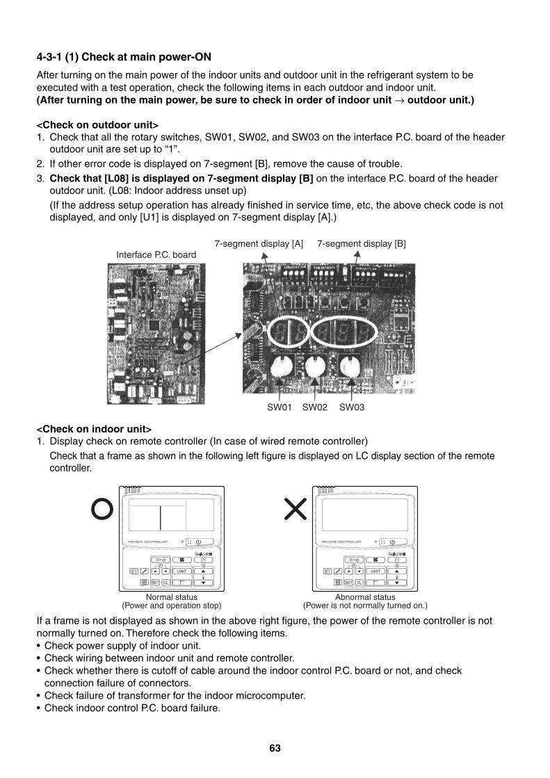
63
Interface P.C. board7-segment display [A]
SW01 SW02 SW03
7-segment display [B]
4-3-1 (1) Check at main power-ON
After turning on the main power of the indoor units and outdoor unit in the refrigerant system to beexecuted with a test operation, check the following items in each outdoor and indoor unit.(After turning on the main power, be sure to check in order of indoor unit → outdoor unit.)
<Check on outdoor unit>1. Check that all the rotary switches, SW01, SW02, and SW03 on the interface P.C. board of the header
outdoor unit are set up to “1”.2. If other error code is displayed on 7-segment [B], remove the cause of trouble.3. Check that [L08] is displayed on 7-segment display [B] on the interface P.C. board of the header
outdoor unit. (L08: Indoor address unset up)(If the address setup operation has already finished in service time, etc, the above check code is notdisplayed, and only [U1] is displayed on 7-segment display [A].)
UNIT
SET CL
UNIT
SET CL
Normal status(Power and operation stop)
Abnormal status(Power is not normally turned on.)
If a frame is not displayed as shown in the above right figure, the power of the remote controller is notnormally turned on. Therefore check the following items.• Check power supply of indoor unit.• Check wiring between indoor unit and remote controller.• Check whether there is cutoff of cable around the indoor control P.C. board or not, and check
connection failure of connectors.• Check failure of transformer for the indoor microcomputer.• Check indoor control P.C. board failure.
<Check on indoor unit>1. Display check on remote controller (In case of wired remote controller)
Check that a frame as shown in the following left figure is displayed on LC display section of the remotecontroller.
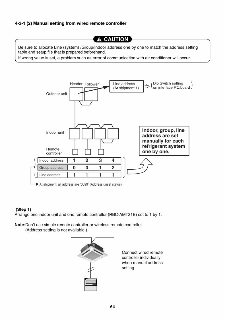
64
4-3-1 (2) Manual setting from wired remote controller
CAUTIONBe sure to allocate Line (system) /Group/Indoor address one by one to match the address settingtable and setup file that is prepared beforehand.If wrong value is set, a problem such as error of communication with air conditioner will occur.
Indoor, group, line address are set manually for each refrigerant system one by one.
Line address (At shipment:1)
Header
Outdoor unit
Indoor unit
Indoor address 1 2 3 40 0 1 2Group address
1 1 1 1Line address
Remote controller
Follower
At shipment, all address are 0099 (Address unset status)
Dip Switch setting on interface P.C.board
(Step 1)Arrange one indoor unit and one remote controller (RBC-AMT21E) set to 1 by 1.
Note:Don’t use simple remote controller or wireless remote controller.(Address setting is not available.)
Connect wired remotecontroller individuallywhen manual addresssetting
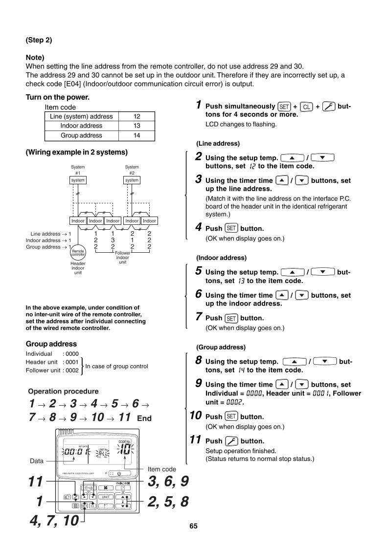
65
UNIT
SET CL
UNIT No.
CODE No.SET DATA
R.C. No.
Operation procedure
1 → 2 → 3 → 4 → 5 → 6 → 7 → 8 → 9 → 10 → 11 End
2, 5, 8 3, 6, 9
14, 7, 10
11
DataItem code
system
Headerindoor
unit
#1
Indoor Indoor Indoor
Line address → 1Indoor address → 1Group address → 1
system
System System#2
Indoor Indoor
Followerindoor
unit
122
132
212
222
Remotecontroller
(Step 2)
Note)When setting the line address from the remote controller, do not use address 29 and 30.The address 29 and 30 cannot be set up in the outdoor unit. Therefore if they are incorrectly set up, acheck code [E04] (Indoor/outdoor communication circuit error) is output.
Turn on the power.
(Wiring example in 2 systems)
In the above example, under condition ofno inter-unit wire of the remote controller,set the address after individual connectingof the wired remote controller.
In case of group control
1 Push simultaneously SET + CL + but-tons for 4 seconds or more.LCD changes to flashing.
(Line address)
2 Using the setup temp. / buttons, set to the item code.
3 Using the timer time / buttons, setup the line address.(Match it with the line address on the interface P.C.board of the header unit in the identical refrigerantsystem.)
4 Push SET button.(OK when display goes on.)
(Indoor address)
5 Using the setup temp. / but-tons, set to the item code.
6 Using the timer time / buttons, setup the indoor address.
7 Push SET button.(OK when display goes on.)
(Group address)
8 Using the setup temp. / but-tons, set to the item code.
9 Using the timer time / buttons, setIndividual = , Header unit = , Followerunit = .
10 Push SET button.(OK when display goes on.)
11 Push button.Setup operation finished.(Status returns to normal stop status.)
Line (system) addressIndoor address
Group address
13
14
12Item code
Group addressIndividual : 0000Header unit : 0001Follower unit : 0002
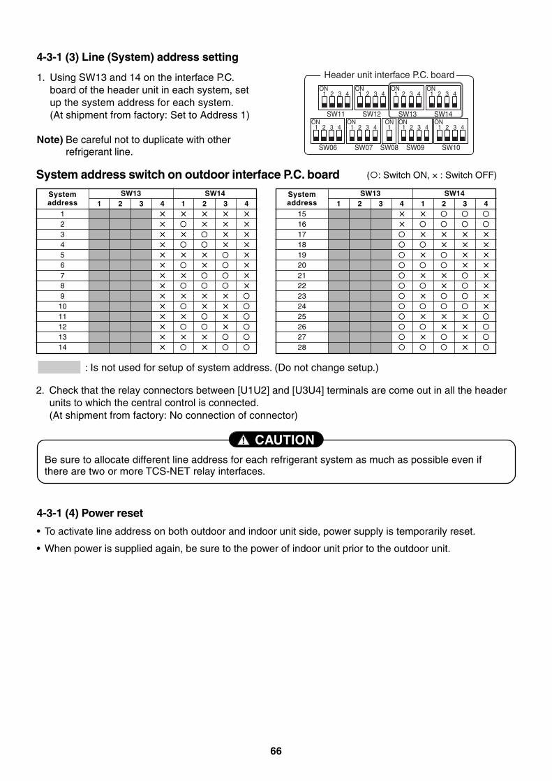
66
4-3-1 (3) Line (System) address setting
CAUTIONBe sure to allocate different line address for each refrigerant system as much as possible even ifthere are two or more TCS-NET relay interfaces.
SW11
1ON
Header unit interface P.C. board
2 3 4
SW12
1ON
2 3 4
SW06
1ON
2 3 4
SW07
1ON ONON ON
2 3 4
SW09SW08
11 2 3 4
SW10
1 2 3 4
SW13
1ON
2 3 4
SW14
1ON
2 3 4
1. Using SW13 and 14 on the interface P.C.board of the header unit in each system, setup the system address for each system.(At shipment from factory: Set to Address 1)
Note) Be careful not to duplicate with otherrefrigerant line.
Systemaddress
123456789
1011121314
SW13 SW141 2 3 4 1 2 3 4
× × × × ×× × × ×× × × ×× × ×× × × ×× × ×× × ×× ×× × × ×× × ×× × ×× ×× × ×× ×
Systemaddress
1516171819202122232425262728
SW13 SW141 2 3 4 1 2 3 4
× ××
× × × ×× × ×
× × ×× ×
× × ×× ×
× ××
× × ×× ×
× ××
2. Check that the relay connectors between [U1U2] and [U3U4] terminals are come out in all the headerunits to which the central control is connected.(At shipment from factory: No connection of connector)
System address switch on outdoor interface P.C. board
: Is not used for setup of system address. (Do not change setup.)
( : Switch ON, × : Switch OFF)
4-3-1 (4) Power reset
• To activate line address on both outdoor and indoor unit side, power supply is temporarily reset.
• When power is supplied again, be sure to the power of indoor unit prior to the outdoor unit.
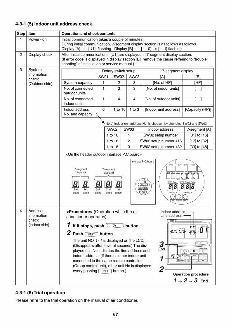
67
4-3-1 (5) Indoor unit address check
Step
1
2
3
4
Item
Power - on
Display check
Systeminformationcheck(Outdoor side)
Addressinformationcheck(indoor side)
Operation and check contents
Initial communication takes a couple of minutes.During initial communication, 7-segment display section is as follows as follows.Display [A] --- [U1], flashing Display [B] --- [ - - 0] --> [ - - i] flashing
After initial communications, [U1] are displayed in 7-segment display section.(If error code is displayed in display section [B], remove the cause reffering to “troubleshooting” of installation or service manual.)
<Procedure> (Operation while the airconditioner operates)
1 If it stops, push button.
2 Push UNIT button.
The unit NO is displayed on the LCD.(Disappears after several seconds) The dis-played unit No indicates the line address andindoor address. (If there is other indoor unitconnected to the same remote controller(Group control unit), other unit No is displayedevery pushing UNIT button.)
Operation procedure
1 → 2 → 3 End
Indoor addressLine address
End
UNIT
SET CL
UNIT No.
CODE No.SET DATA
R.C. No.
3
12
System capacity
No. of connectedoutdoor units
No. of connectedindoor units
Indoor addressNo. and capacity
SW01
1
1
1
6
SW02
2
3
4
1 to 16
[A]
[No. of HP]
[No. of indoor units]
[No. of outdoor units]
[Indoor unit address]
SW03
3
3
4
1 to 3
[B]
[HP]
[ ]
[ ]
[Capacity (HP)]
Rotary switch setup 7-segment display
SW02
1 to 16
1 to 16
1 to 16
SW03
1
2
3
Indoor address
SW02 setup number
SW02 setup number +16
SW02 setup number +32
7-segment [A]
[01] to [16]
[17] to [32]
[33] to [48]
Note) Indoor unit address No. is choosen by changing SW02 and SW03.
<On the header outdoor interface P.C.board>
4-3-1 (6) Trial operation
Please refre to the trial operation on the manual of air conditioner.
7-segment display A
2nd.place
1st.place
7-segment display B
Interlace P.C. board
3rd.place
2nd.place
1st.place
SW01 SW02
Display A Display B
D600 D601
CN30 CN31
SW06 SW07 SW09SW08
CN32 SW04
SW05 SW15
SW03
D602 D603 D604
SW01 SW02
Display A Display B
D600 D601
CN30 CN31
SW06 SW07 SW09SW08
CN32 SW04
SW05 SW15
SW03
D602 D603 D604
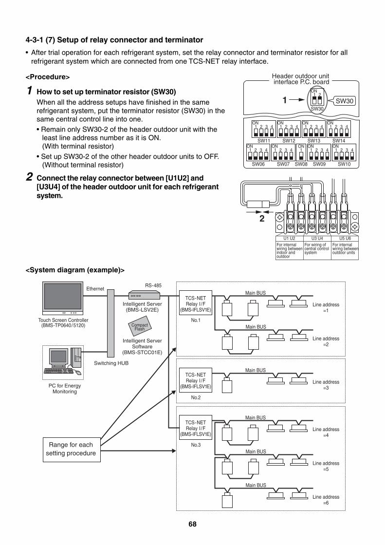
68
4-3-1 (7) Setup of relay connector and terminator
• After trial operation for each refrigerant system, set the relay connector and terminator resistor for allrefrigerant system which are connected from one TCS-NET relay interface.
<Procedure>
1 How to set up terminator resistor (SW30)When all the address setups have finished in the samerefrigerant system, put the terminator resistor (SW30) in thesame central control line into one.• Remain only SW30-2 of the header outdoor unit with the
least line address number as it is ON.(With terminal resistor)
• Set up SW30-2 of the other header outdoor units to OFF.(Without terminal resistor)
2 Connect the relay connector between [U1U2] and[U3U4] of the header outdoor unit for each refrigerantsystem.
Header outdoor unit interface P.C. board
SW11
1ON
2 3 4
SW12
1ON
2 3 4
SW06
1ON
2 3 4
SW07
1ON ONON ON
2 3 4
SW09SW08
11 2 3 4
SW10
1 2 3 4
SW13
1ON
2 3 4
SW14
1ON
2 3 4
SW30SW30
1ON
2
1
2
U1 U2For internal wiring between indoor and outdoor
U3 U4For wiring of central control system
U5 U6For internal wiring betweenoutdoor units
TCS-NETRelay I /F
(BMS-IFLSV1E)
No.1
Main BUS
Main BUS
Ethernet
Touch Screen Controller(BMS-TP0640/5120)
Switching HUB
PC for EnergyMonitoring
InteIligent Server(BMS-LSV2E)
InteIligent ServerSoftware
(BMS-STCC01E)
RS-485
Line address=1
Line address=2
TCS-NETRelay I /F
(BMS-IFLSV1E)
No.3
Main BUS
Main BUS
Line address=4
Line address=5
Main BUS
Line address=6
TCS-NETRelay I /F
(BMS-IFLSV1E)
No.2
Main BUS
Line address=3
CompactFlash
Range for eachsetting procedure
<System diagram (example)>
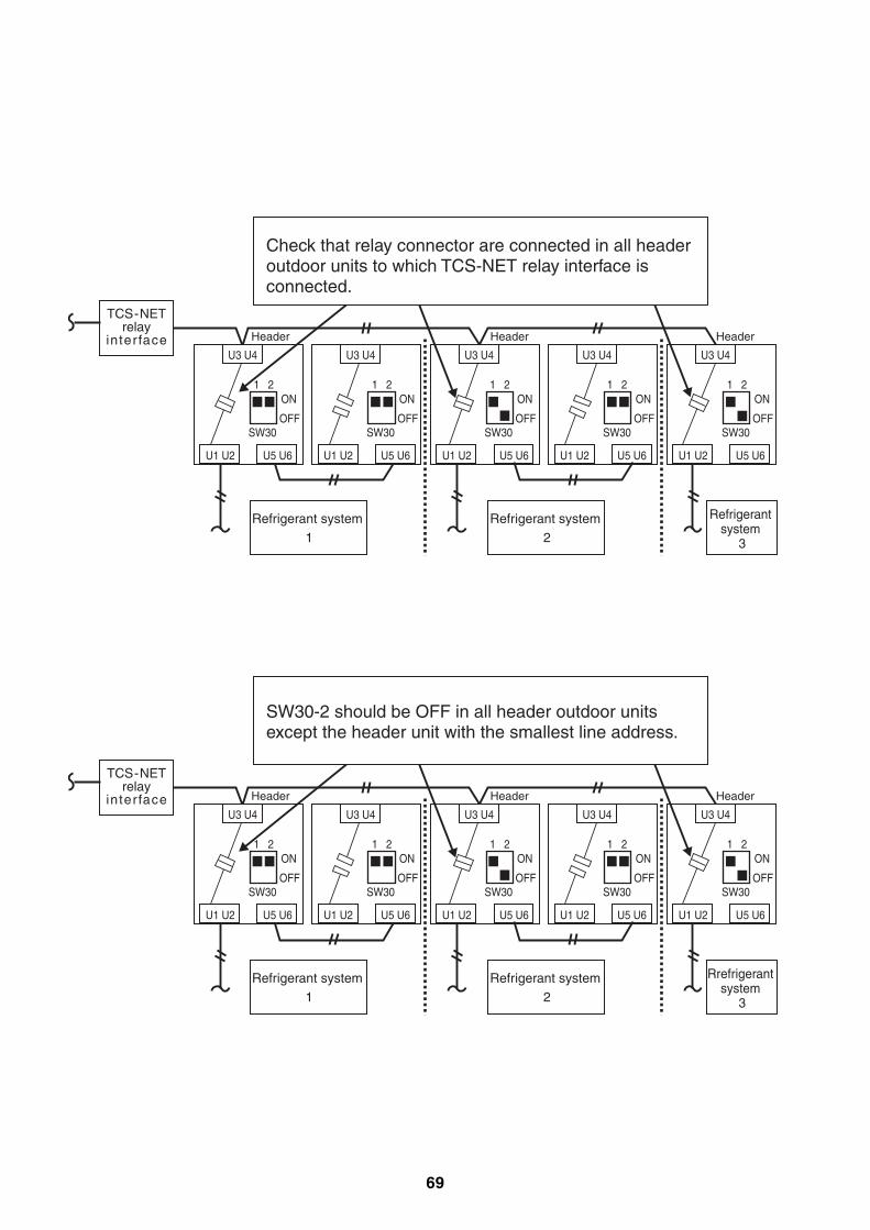
69
TCS-NETrelay
interface Header Header Header
U3 U4
ON1 2
OFFSW30
U1 U2 U5 U6
ON1 2
OFFSW30
ON1 2
OFFSW30
ON1 2
OFFSW30
ON1 2
OFFSW30
U3 U4
U1 U2 U5 U6
U3 U4
U1 U2 U5 U6
U3 U4
U1 U2 U5 U6
U3 U4
U1 U2 U5 U6
Refrigerant system 1
Refrigerant system 2
Refrigerant system
3
Check that relay connector are connected in all headeroutdoor units to which TCS-NET relay interface is connected.
TCS-NETrelay
interface Header Header Header
U3 U4
ON1 2
OFFSW30
U1 U2 U5 U6
ON1 2
OFFSW30
ON1 2
OFFSW30
ON1 2
OFFSW30
ON1 2
OFFSW30
U3 U4
U1 U2 U5 U6
U3 U4
U1 U2 U5 U6
U3 U4
U1 U2 U5 U6
U3 U4
U1 U2 U5 U6
SW30-2 should be OFF in all header outdoor unitsexcept the header unit with the smallest line address.
Refrigerant system 1
Refrigerant system 2
Rrefrigerant system
3
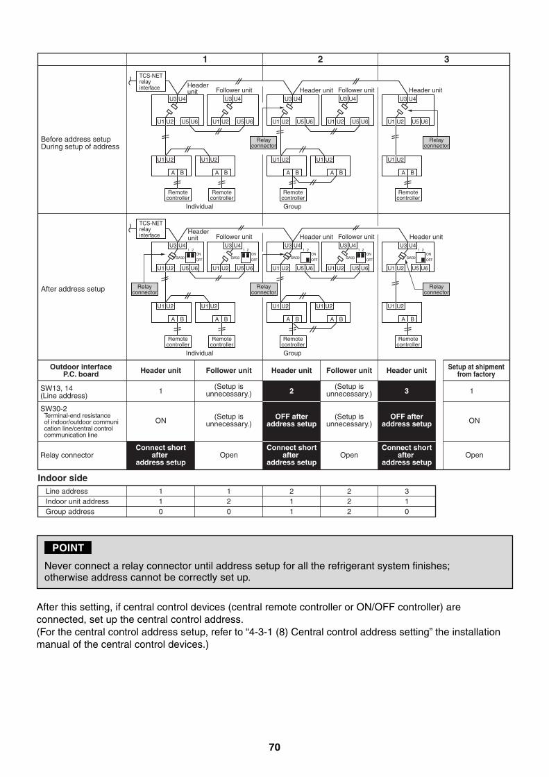
70
After this setting, if central control devices (central remote controller or ON/OFF controller) areconnected, set up the central control address.(For the central control address setup, refer to “4-3-1 (8) Central control address setting” the installationmanual of the central control devices.)
POINT
Never connect a relay connector until address setup for all the refrigerant system finishes;otherwise address cannot be correctly set up.
Before address setupDuring setup of address
After address setup
SW13, 14(Line address)
SW30-2Terminal-end resistance of indoor/outdoor communi cation line/central control communication line
Relay connector
Indoor sideLine addressIndoor unit addressGroup address
110
120
211
222
310
Connect shortafter
address setup
Connect shortafter
address setup
Connect shortafter
address setup
Setup at shipmentfrom factory
U3 U4
U1 U2 U5 U6
U1 U2
A B
Header unit
TCS-NETrelay interface
Individual Group
Remotecontroller
U3 U4
U1 U2 U5 U6
U1 U2
A B
Follower unit
Remotecontroller
Relayconnector
U3 U4
U1 U2 U5 U6
U1 U2
A B
Remotecontroller
U3 U4
U1 U2 U5 U6
U1 U2
A B
Follower unitU3 U4
U1 U2 U5 U6
U1 U2
A B
Header unit
Remotecontroller
Relayconnector
U3 U4
U1 U2 U5 U6
U1 U2
A B
Header unit
Header unit
Header unit Header unit
Individual Group
Remotecontroller
U3 U421
SW30ON
OFF
U1 U2 U5 U6
U1 U2
A B
Follower unit
Remotecontroller
Relayconnector
U3 U4
U1 U2 U5 U6
U1 U2
A B
Remotecontroller
U3 U4
U1 U2 U5 U6
U1 U2
A B
Follower unitU3 U4
U1 U2 U5 U6
U1 U2
A B
Remotecontroller
Relayconnector
Relayconnector
Open
ON
1 2
1 2 3
3 1
Header unit Follower unit Follower unitHeader unit Header unit
ON
Open Open
(Setup isunnecessary.)
(Setup isunnecessary.)
OFF afteraddress setup
OFF afteraddress setup
(Setup isunnecessary.)
(Setup isunnecessary.)
Outdoor interfaceP.C. board
21
SW30ON
OFF
21
SW30 SW30ON
OFF
21
SW30ON
OFF
21ON
OFF
TCS-NETrelay interface
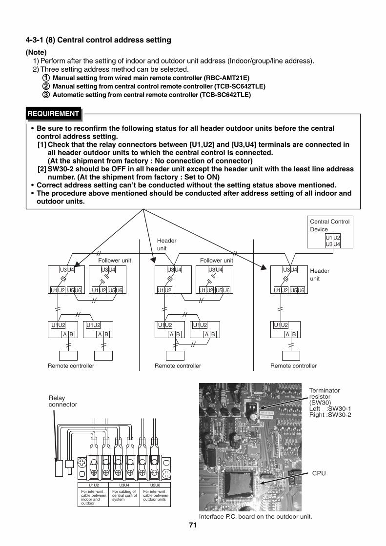
71
U3U4
U1
A
U2
B
U1
A
U2
B
U1
A
U2
B
U1
A
U2
B
U1
A
U2
B
Remote controller Remote controller Remote controller
Headerunit
Central ControlDevice
Follower unitFollower unit
Headerunit
U1U3
U2U4
U1U2 U5U6
U3U4 U3U4 U3U4
U1U2 U5U6 U1U2 U1U2 U5U6
U3U4
U1U2 U5U6
4-3-1 (8) Central control address setting
(Note)1) Perform after the setting of indoor and outdoor unit address (Indoor/group/line address).2) Three setting address method can be selected.
1 Manual setting from wired main remote controller (RBC-AMT21E)2 Manual setting from central control remote controller (TCB-SC642TLE)3 Automatic setting from central remote controller (TCB-SC642TLE)
• Be sure to reconfirm the following status for all header outdoor units before the centralcontrol address setting.[1] Check that the relay connectors between [U1,U2] and [U3,U4] terminals are connected in
all header outdoor units to which the central control is connected.(At the shipment from factory : No connection of connector)
[2] SW30-2 should be OFF in all header unit except the header unit with the least line addressnumber. (At the shipment from factory : Set to ON)
• Correct address setting can’t be conducted without the setting status above mentioned.• The procedure above mentioned should be conducted after address setting of all indoor and
outdoor units.
REQUIREMENT
U1U2 U3U4
For inter-unitcable betweenindoor andoutdoor
For cabling ofcentral controlsystem
U5U6
For inter-unitcable betweenoutdoor units
Relay connector
Terminatorresistor(SW30)Left :SW30-1Right :SW30-2
CPU
Interface P.C. board on the outdoor unit.
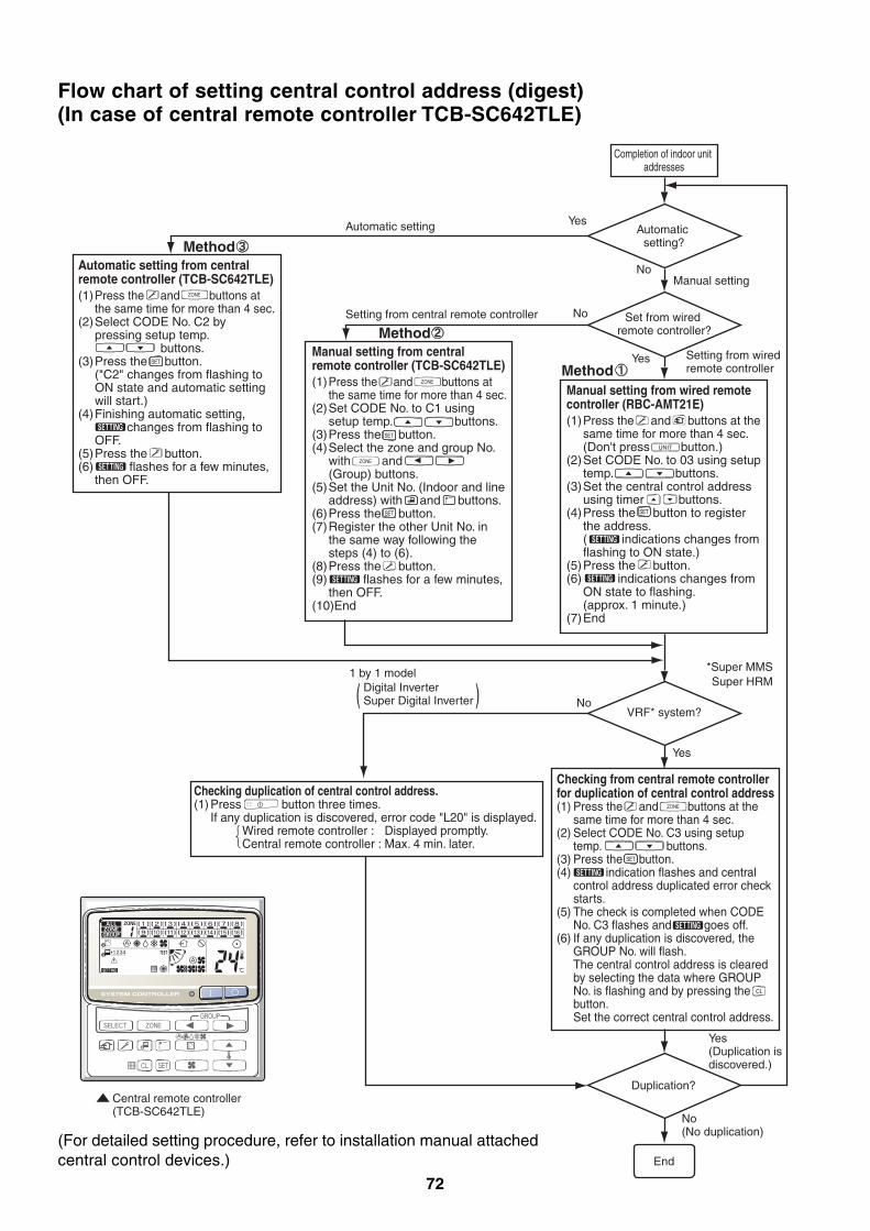
72
Flow chart of setting central control address (digest)(In case of central remote controller TCB-SC642TLE)
Automatic setting?
Completion of indoor unit addresses
Set from wired remote controller?
Manual setting
Yes
YesMethod
Yes
No(No duplication)
Yes (Duplication is discovered.)
VRF* system?
Duplication?
*Super MMSSuper HRM
Automatic setting
Setting from central remote controller
Digital Inverter Super Digital Inverter
1 by 1 model
No
No
No
Central remote controller(TCB-SC642TLE)
End
Checking from central remote controller for duplication of central control address(1) Press the and buttons at the
same time for more than 4 sec.(2) Select CODE No. C3 using setup
temp. buttons.(3) Press the button.(4) indication flashes and central
control address duplicated error check starts.
(5) The check is completed when CODE No. C3 flashes and goes off.
(6) If any duplication is discovered, the GROUP No. will flash.
The central control address is cleared by selecting the data where GROUP No. is flashing and by pressing the button.
Set the correct central control address.
Checking duplication of central control address.(1) Press button three times. If any duplication is discovered, error code "L20" is displayed. Wired remote controller : Displayed promptly. Central remote controller : Max. 4 min. later.
Method
Method
Manual setting from wired remote controller (RBC-AMT21E)(1) Press the and buttons at the
same time for more than 4 sec. (Don't press button.)(2) Set CODE No. to 03 using setup
temp. buttons.(3) Set the central control address
using timer buttons.(4) Press the button to register
the address. ( indications changes from
flashing to ON state.)(5) Press the button.(6) indications changes from
ON state to flashing. (approx. 1 minute.)(7) End
Manual setting from central remote controller (TCB-SC642TLE)(1) Press the and buttons at
the same time for more than 4 sec.(2) Set CODE No. to C1 using
setup temp. buttons.(3) Press the button.(4) Select the zone and group No.
with and (Group) buttons.
(5) Set the Unit No. (Indoor and line address) with and buttons.
(6) Press the button.(7) Register the other Unit No. in
the same way following the steps (4) to (6).
(8) Press the button.(9) flashes for a few minutes,
then OFF.(10)End
Automatic setting from central remote controller (TCB-SC642TLE)(1) Press the and buttons at
the same time for more than 4 sec.(2) Select CODE No. C2 by
pressing setup temp. buttons.
(3) Press the button. ("C2" changes from flashing to
ON state and automatic setting will start.)
(4) Finishing automatic setting, changes from flashing to OFF.
(5) Press the button.(6) flashes for a few minutes,
then OFF.
Setting from wired remote controller
SET
SET
SET
UNIT
SET
SET
CL
(For detailed setting procedure, refer to installation manual attachedcentral control devices.)

73
4-3-1 (9) Trial operation for central controller (TCB-SC642TLE)
1 Test run of the central controller(1) Power on for all indoor units. Next, power on for central controller.
will flash, checking the indoor unit address automatically.
(2) If group No. displayed on central controllers is not same as indoor unit No.** In case of group control, main unit No. only.
2 How to perform an air conditioner test run(1) Hold down the button of the central controller for at least four seconds.
• During the test run, “TEST” appears on the LCD display.(2) Press the and buttons.
• The temperature cannot be adjusted at the “TEST” position.
Do not use this procedure except when performing a test run since it will strain the equipment.(3) Upon completion of the operation, press the button, and check that “TEST” on the LCD
display has gone off.
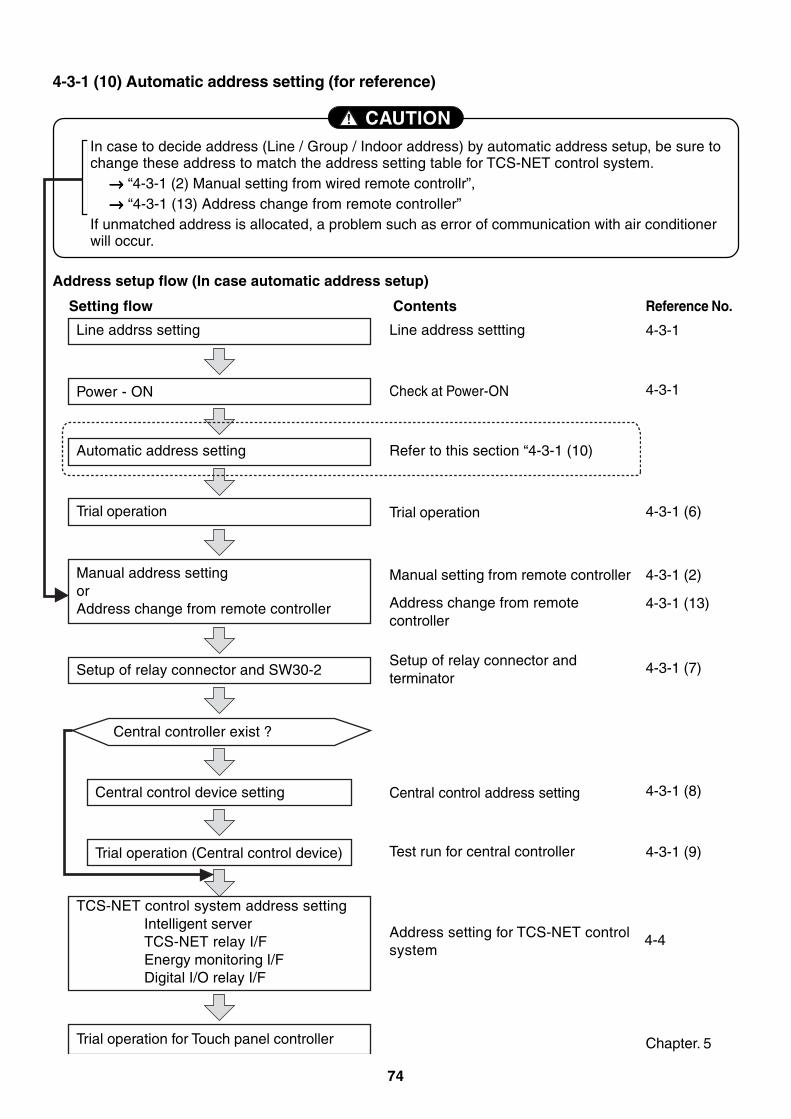
74
CAUTIONIn case to decide address (Line / Group / Indoor address) by automatic address setup, be sure tochange these address to match the address setting table for TCS-NET control system.
→→→→→ “4-3-1 (2) Manual setting from wired remote controllr”,→→→→→ “4-3-1 (13) Address change from remote controller”
If unmatched address is allocated, a problem such as error of communication with air conditionerwill occur.
4-3-1 (10) Automatic address setting (for reference)
Setting flow
Line addrss setting
Contents Reference No.
Power - ON
Automatic address setting
Line address settting
Check at Power-ON
Refer to this section “4-3-1 (10)
Trial operation
Manual setting from remote controller
Address change from remotecontroller
4-3-1
Trial operation
Manual address settingorAddress change from remote controller
Setup of relay connector and SW30-2
Central control device setting
Central controller exist ?
Trial operation (Central control device)
TCS-NET control system address settingIntelligent serverTCS-NET relay I/FEnergy monitoring I/FDigital I/O relay I/F
Setup of relay connector andterminator
Central control address setting
Test run for central controller
Address setting for TCS-NET controlsystem
4-3-1
4-3-1 (6)
4-3-1 (2)
4-3-1 (13)
4-3-1 (7)
4-3-1 (8)
4-3-1 (9)
4-4
Address setup flow (In case automatic address setup)
Chapter. 5Trial operation for Touch panel controller
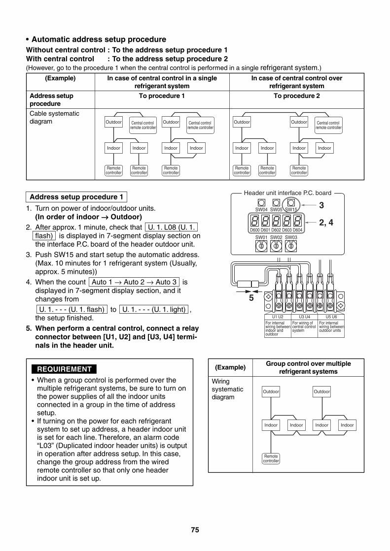
75
Address setup procedure 1
1. Turn on power of indoor/outdoor units.(In order of indoor →→→→→ Outdoor)
2. After approx. 1 minute, check that U. 1. L08 (U. 1.flash) is displayed in 7-segment display section onthe interface P.C. board of the header outdoor unit.
3. Push SW15 and start setup the automatic address.(Max. 10 minutes for 1 refrigerant system (Usually,approx. 5 minutes))
4. When the count Auto 1 → Auto 2 → Auto 3 isdisplayed in 7-segment display section, and itchanges from U. 1. - - - (U. 1. flash) to U. 1. - - - (U. 1. light) ,the setup finished.
5. When perform a central control, connect a relayconnector between [U1, U2] and [U3, U4] termi-nals in the header unit.
SW04
SW011 1 1
SW05 SW15
D600 D601 D602 D603 D604
SW02 SW03
3
5
2, 4
Header unit interface P.C. board
U1 U2For internal wiring between indoor and outdoor
U3 U4For wiring of central control system
U5 U6For internal wiring betweenoutdoor units
Outdoor
Indoor Indoor
Remotecontroller
Remotecontroller
Central control remote controller
Outdoor
Indoor Indoor
Remotecontroller
Central control remote controller
Outdoor
Indoor Indoor
Remotecontroller
Remotecontroller
Outdoor
Indoor Indoor
Remotecontroller
Central control remote controller
(Example)
Address setupprocedure
Cable systematicdiagram
(Example)
Wiringsystematicdiagram
Outdoor
Indoor Indoor
Remotecontroller
Outdoor
Indoor Indoor
• When a group control is performed over themultiple refrigerant systems, be sure to turn onthe power supplies of all the indoor unitsconnected in a group in the time of addresssetup.
• If turning on the power for each refrigerantsystem to set up address, a header indoor unitis set for each line. Therefore, an alarm code“L03” (Duplicated indoor header units) is outputin operation after address setup. In this case,change the group address from the wiredremote controller so that only one headerindoor unit is set up.
Group control over multiplerefrigerant systems
• Automatic address setup procedureWithout central control : To the address setup procedure 1With central control : To the address setup procedure 2(However, go to the procedure 1 when the central control is performed in a single refrigerant system.)
REQUIREMENT
In case of central control in a singlerefrigerant system
To procedure 1
In case of central control overrefrigerant system
To procedure 2
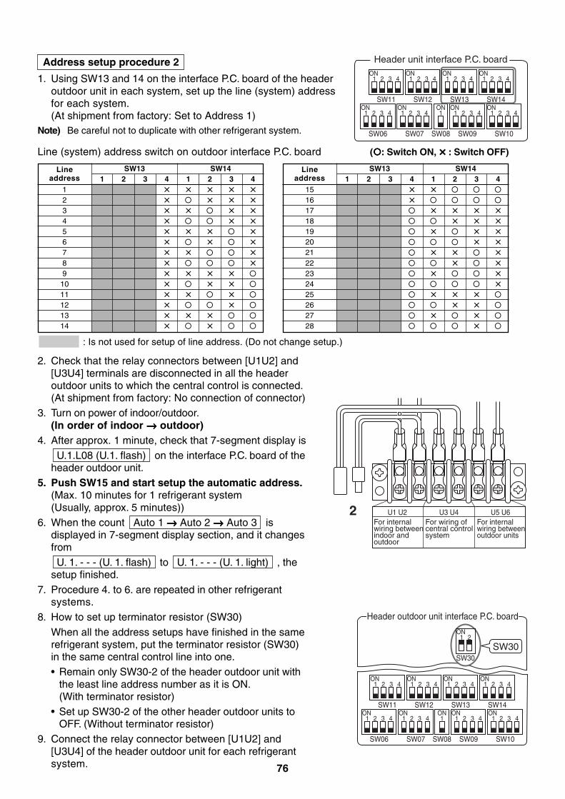
76
Line (system) address switch on outdoor interface P.C. board ( : Switch ON, × : Switch OFF)
2. Check that the relay connectors between [U1U2] and[U3U4] terminals are disconnected in all the headeroutdoor units to which the central control is connected.(At shipment from factory: No connection of connector)
3. Turn on power of indoor/outdoor.(In order of indoor →→→→→ outdoor)
4. After approx. 1 minute, check that 7-segment display is U.1.L08 (U.1. flash) on the interface P.C. board of theheader outdoor unit.
5. Push SW15 and start setup the automatic address.(Max. 10 minutes for 1 refrigerant system(Usually, approx. 5 minutes))
6. When the count Auto 1 →→→→→ Auto 2 →→→→→ Auto 3 isdisplayed in 7-segment display section, and it changesfrom U. 1. - - - (U. 1. flash) to U. 1. - - - (U. 1. light) , thesetup finished.
7. Procedure 4. to 6. are repeated in other refrigerantsystems.
8. How to set up terminator resistor (SW30)
When all the address setups have finished in the samerefrigerant system, put the terminator resistor (SW30)in the same central control line into one.• Remain only SW30-2 of the header outdoor unit with
the least line address number as it is ON.(With terminator resistor)
• Set up SW30-2 of the other header outdoor units toOFF. (Without terminator resistor)
9. Connect the relay connector between [U1U2] and[U3U4] of the header outdoor unit for each refrigerantsystem.
: Is not used for setup of line address. (Do not change setup.)
Lineaddress
123456789
1011121314
SW13 SW141 2 3 4 1 2 3 4
× × × × ×× × × ×× × × ×× × ×× × × ×× × ×× × ×× ×× × × ×× × ×× × ×× ×× × ×× ×
Lineaddress
1516171819202122232425262728
SW13 SW141 2 3 4 1 2 3 4
× ××
× × × ×× × ×
× × ×× ×
× × ×× ×
× ××
× × ×× ×
× ××
U1 U2For internal wiring between indoor and outdoor
U3 U4For wiring of central control system
U5 U6For internal wiring betweenoutdoor units
2
Header outdoor unit interface P.C. board
SW11
1ON
2 3 4
SW12
1ON
2 3 4
SW06
1ON
2 3 4
SW07
1ON ONON ON
2 3 4
SW09SW08
11 2 3 4
SW10
1 2 3 4
SW13
1ON
2 3 4
SW14
1ON
2 3 4
SW30SW30
1ON
2
SW11
1ON
Header unit interface P.C. board
2 3 4
SW12
1ON
2 3 4
SW06
1ON
2 3 4
SW07
1ON ONON ON
2 3 4
SW09SW08
11 2 3 4
SW10
1 2 3 4
SW13
1ON
2 3 4
SW14
1ON
2 3 4
Address setup procedure 2
1. Using SW13 and 14 on the interface P.C. board of the headeroutdoor unit in each system, set up the line (system) addressfor each system.(At shipment from factory: Set to Address 1)
Note) Be careful not to duplicate with other refrigerant system.
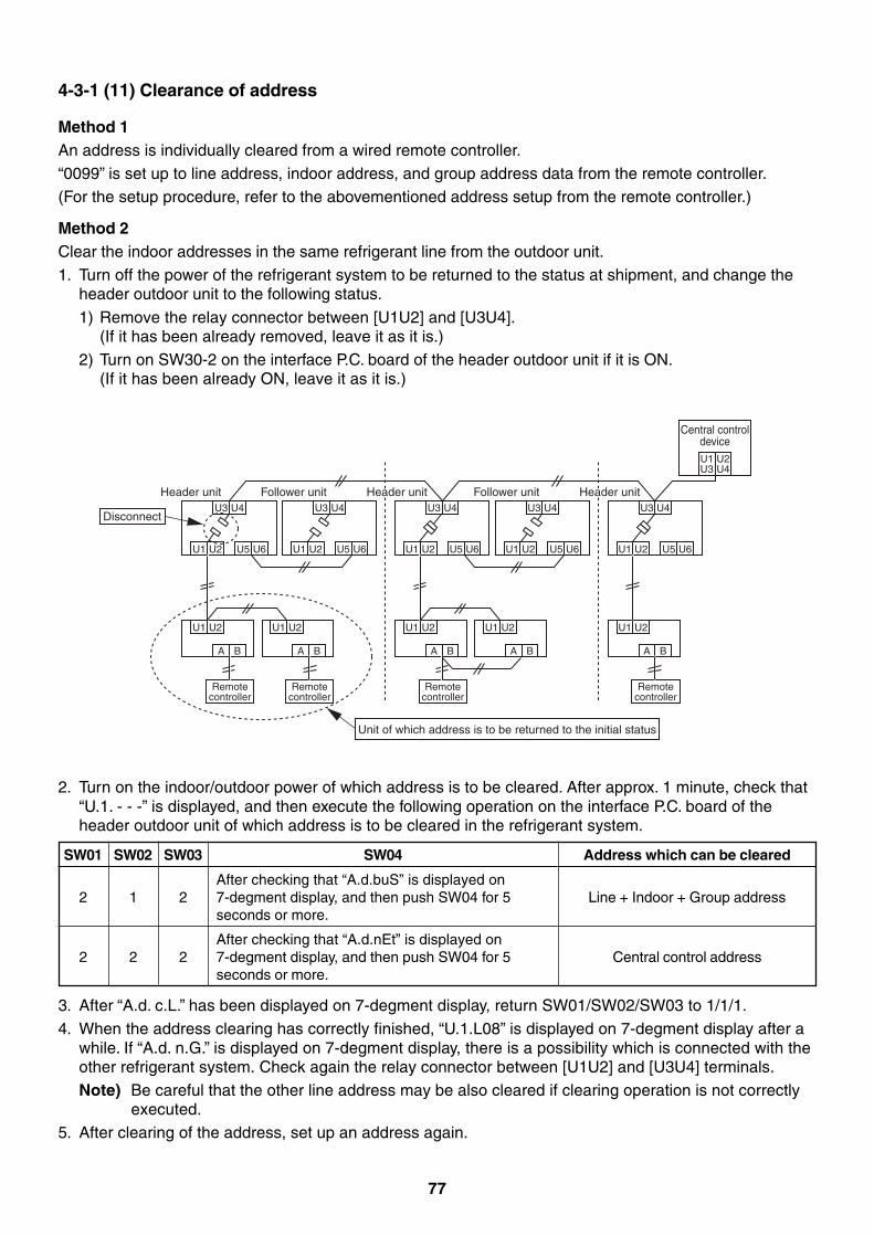
77
4-3-1 (11) Clearance of address
Method 1An address is individually cleared from a wired remote controller.“0099” is set up to line address, indoor address, and group address data from the remote controller.(For the setup procedure, refer to the abovementioned address setup from the remote controller.)
Method 2Clear the indoor addresses in the same refrigerant line from the outdoor unit.1. Turn off the power of the refrigerant system to be returned to the status at shipment, and change the
header outdoor unit to the following status.
1) Remove the relay connector between [U1U2] and [U3U4].(If it has been already removed, leave it as it is.)
2) Turn on SW30-2 on the interface P.C. board of the header outdoor unit if it is ON.(If it has been already ON, leave it as it is.)
3. After “A.d. c.L.” has been displayed on 7-degment display, return SW01/SW02/SW03 to 1/1/1.4. When the address clearing has correctly finished, “U.1.L08” is displayed on 7-degment display after a
while. If “A.d. n.G.” is displayed on 7-degment display, there is a possibility which is connected with theother refrigerant system. Check again the relay connector between [U1U2] and [U3U4] terminals.Note) Be careful that the other line address may be also cleared if clearing operation is not correctly
executed.5. After clearing of the address, set up an address again.
2. Turn on the indoor/outdoor power of which address is to be cleared. After approx. 1 minute, check that“U.1. - - -” is displayed, and then execute the following operation on the interface P.C. board of theheader outdoor unit of which address is to be cleared in the refrigerant system.
U3 U4
U1 U2 U5 U6
U1 U2
A B
Header unit
Disconnect
Remote controller
U3 U4
U1 U2 U5 U6
U1 U2
A B
Follower unit
Remote controller
U3 U4
U1 U2 U5 U6
U1 U2
A B
Remote controller
U3 U4
U1 U2 U5 U6
U1 U2
A B
Follower unitU3 U4
U1 U2
U1U3
U2U4
U5 U6
U1 U2
A B
Remote controller
Center unitCenter unit Center unitCenter unitHeader unit Header unit
Central control device
Unit of which address is to be returned to the initial status
Address which can be cleared
Line + Indoor + Group address
Central control address
SW01 SW02 SW03
2 1 2
2 2 2
SW04
After checking that “A.d.buS” is displayed on7-degment display, and then push SW04 for 5seconds or more.
After checking that “A.d.nEt” is displayed on7-degment display, and then push SW04 for 5seconds or more.
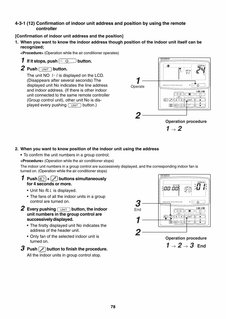
78
Operation procedure
1 → 2
Operation procedure
1 → 2 → 3 End
Operate
End
UNIT
SET CL
UNIT No.
CODE No.
UNIT
SET CL
UNIT No.
CODE No.SET DATA
R.C. No.
2
3
1
1
2
4-3-1 (12) Confirmation of indoor unit address and position by using the remotecontroller
[Confirmation of indoor unit address and the position]1. When you want to know the indoor address though position of the indoor unit itself can be
recognized;<Procedure> (Operation while the air conditioner operates)
1 If it stops, push button.
2 Push UNIT button.The unit NO is displayed on the LCD.(Disappears after several seconds) Thedisplayed unit No indicates the line addressand indoor address. (If there is other indoorunit connected to the same remote controller(Group control unit), other unit No is dis-played every pushing UNIT button.)
2. When you want to know position of the indoor unit using the address• To confirm the unit numbers in a group control;<Procedure> (Operation while the air conditioner stops)
The indoor unit numbers in a group control are successively displayed, and the corresponding indoor fan isturned on. (Operation while the air conditioner stops)
1 Push + buttons simultaneouslyfor 4 seconds or more.
• Unit No is displayed.• The fans of all the indoor units in a group
control are turned on.
2 Every pushing UNIT button, the indoorunit numbers in the group control aresuccessively displayed.• The firstly displayed unit No indicates the
address of the header unit.• Only fan of the selected indoor unit is
turned on.
3 Push button to finish the procedure.All the indoor units in group control stop.
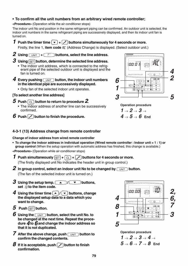
79
Operation procedure
1 → 2 → 3 → 4 → 5 → 6 End
16
5
4
3
2UNIT
SET CL
UNIT No.
CODE No.SET DATA
R.C. No.
• To confirm all the unit numbers from an arbitrary wired remote controller;<Procedure> (Operation while the air conditioner stops)
The indoor unit No and position in the same refrigerant piping can be confirmed. An outdoor unit is selected, theindoor unit numbers in the same refrigerant piping are successively displayed, and then its indoor unit fan isturned on.
1 Push the timer time + buttons simultaneously for 4 seconds or more.Firstly, the line 1, item code (Address Change) is displayed. (Select outdoor unit.)
3 Using the setup temp. / buttons,set to the item code.
4 Using the timer time / buttons, changethe displayed setup data to a data which youwant to change.
5 Push SET button.
6 Using the UNIT button, select the unit No. tobe changed at the next time. Repeat the proce-dure 4 to 6 and change the indoor address sothat it is not duplicated.
7 After the above change, push UNIT button toconfirm the changed contents.
8 If it is acceptable, push button to finishconfirmation.
2 Using UNIT + buttons, select the line address.
3 Using SET button, determine the selected line address.• The indoor unit address, which is connected to the refrig-
erant pipe of the selected outdoor unit is displayed and thefan is turned on.
4 Every pushing UNIT button, the indoor unit numbersin the identical pipe are successively displayed.• Only fan of the selected indoor unit operates.
[To select another line address]
5 Push CL button to return to procedure 2.• The indoor address of another line can be successively
confirmed.
6 Push button to finish the procedure.
4-3-1 (13) Address change from remote controller
Change of indoor address from wired remote controller
• To change the indoor address in individual operation (Wired remote controller : Indoor unit = 1 : 1) orgroup control (When the setup operation with automatic address has finished, this change is available.)
<Procedure> (Operation while air conditioner stops)
1 Push simultaneously SET + CL + buttons for 4 seconds or more.(The firstly displayed unit No indicates the header unit in group control.)
2 In group control, select an indoor unit No to be changed by UNIT button.(The fan of the selected indoor unit is turned on.)
Operation procedure
1 → 2 → 3 → 4 → 5 → 6 → 7 → 8 End
48
UNIT
SET CL
UNIT No.
CODE No.SET DATA
R.C. No.
15
2,6,73
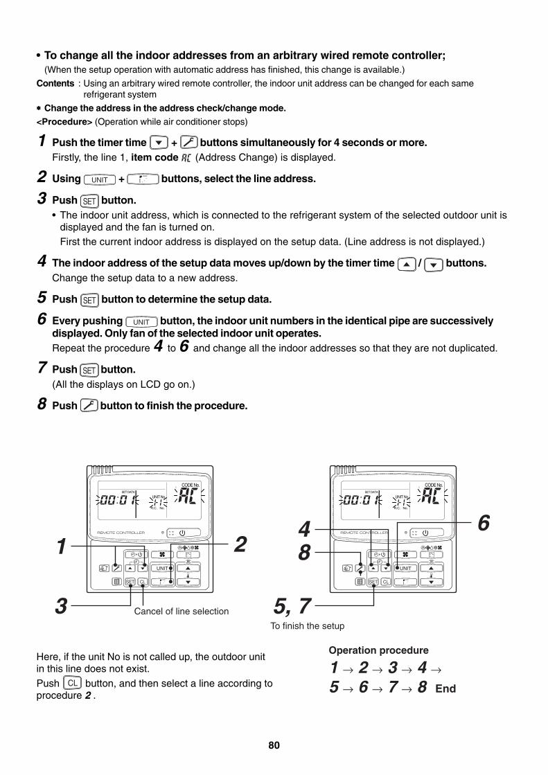
80
Operation procedure
1 → 2 → 3 → 4 → 5 → 6 → 7 → 8 End
84 6
5, 7
UNIT
SET CL
UNIT No.
CODE No.SET DATA
R.C. No.
1
3
2UNIT
SET CL
UNIT No.
CODE No.SET DATA
R.C. No.
To finish the setup
Cancel of line selection
Here, if the unit No is not called up, the outdoor unitin this line does not exist.
Push CL button, and then select a line according toprocedure 2 .
• To change all the indoor addresses from an arbitrary wired remote controller;(When the setup operation with automatic address has finished, this change is available.)
Contents : Using an arbitrary wired remote controller, the indoor unit address can be changed for each samerefrigerant system
∗∗∗∗∗ Change the address in the address check/change mode.<Procedure> (Operation while air conditioner stops)
1 Push the timer time + buttons simultaneously for 4 seconds or more.Firstly, the line 1, item code (Address Change) is displayed.
2 Using UNIT + buttons, select the line address.
3 Push SET button.• The indoor unit address, which is connected to the refrigerant system of the selected outdoor unit is
displayed and the fan is turned on.First the current indoor address is displayed on the setup data. (Line address is not displayed.)
4 The indoor address of the setup data moves up/down by the timer time / buttons.Change the setup data to a new address.
5 Push SET button to determine the setup data.
6 Every pushing UNIT button, the indoor unit numbers in the identical pipe are successivelydisplayed. Only fan of the selected indoor unit operates.Repeat the procedure 4 to 6 and change all the indoor addresses so that they are not duplicated.
7 Push SET button.(All the displays on LCD go on.)
8 Push button to finish the procedure.
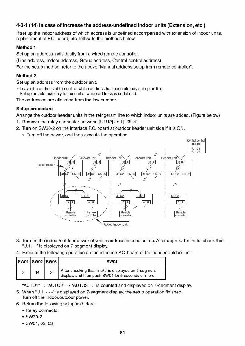
81
4-3-1 (14) In case of increase the address-undefined indoor units (Extension, etc.)
If set up the indoor address of which address is undefined accompanied with extension of indoor units,replacement of P.C. board, etc, follow to the methods below.
Method 1Set up an address individually from a wired remote controller.(Line address, Indoor address, Group address, Central control address)For the setup method, refer to the above “Manual address setup from remote controller”.
Method 2Set up an address from the outdoor unit.∗ Leave the address of the unit of which address has been already set up as it is.
Set up an address only to the unit of which address is undefined.
The addresses are allocated from the low number.
Setup procedureArrange the outdoor header units in the refrigerant line to which indoor units are added. (Figure below)1. Remove the relay connector between [U1U2] and [U3U4].2. Turn on SW30-2 on the interface P.C. board at outdoor header unit side if it is ON.
∗ Turn off the power, and then execute the operation.
“AUTO1” → “AUTO2” → “AUTO3” … is counted and displayed on 7-degment display.5. When “U.1. - - -” is displayed on 7-segment display, the setup operation finished.
Turn off the indoor/outdoor power.6. Return the following setup as before.
• Relay connector• SW30-2• SW01, 02, 03
U3 U4
U1 U2 U5 U6
U1 U2
A B
Header unit
Remote controller
U3 U4
U1 U2 U5 U6
U1 U2
A B
Follower unit
Remote controller
U3 U4
U1 U2 U5 U6
U1 U2
A B
Remote controller
U3 U4
U1 U2 U5 U6
U1 U2
A B
Follower unitU3 U4
U1 U2
U1U3
U2U4
U5 U6
U1 U2
A B
Remote controller
Center unitCenter unit Center unitCenter unitHeader unit Header unit
Central control device
Added indoor unit
Disconnect
3. Turn on the indoor/outdoor power of which address is to be set up. After approx. 1 minute, check that“U.1.---” is displayed on 7-segment display.
4. Execute the following operation on the interface P.C. board of the header outdoor unit.
SW04
After checking that “In.At” is displayed on 7-segmentdisplay, and then push SW04 for 5 seconds or more.
SW01 SW02 SW03
2 14 2
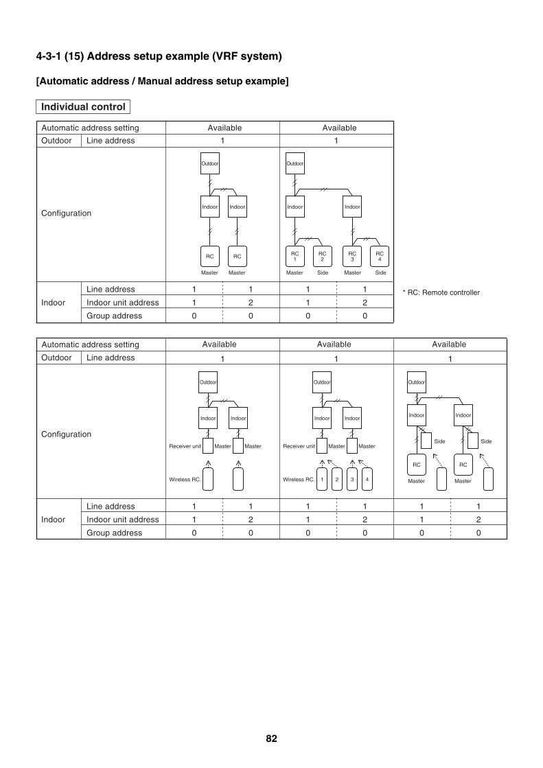
82
4-3-1 (15) Address setup example (VRF system)
[Automatic address / Manual address setup example]
Individual control
Automatic address setting Available Available
Outdoor Line address 1 1
Line address 1 1 1 1
Indoor Indoor unit address 1 2 1 2
Group address 0 0 0 0
Configuration
Outdoor
Indoor Indoor
RC
Master
RC
Master
Outdoor
Indoor
RC1
Master Side Master
* RC: Remote controller
Side
RC2
Indoor
RC3
RC4
Automatic address setting
Outdoor
Configuration
Line address 1 1 1
Line address 1 1 1 1 1 1
Indoor Indoor unit address 1 2 1 2 1 2
Group address 0 0 0 0 0 0
Outdoor
Indoor
RC
Master
Outdoor
Indoor Indoor
MasterReceiver unit
Wireless RC.
Receiver unit
Wireless RC.
Master
Outdoor
Indoor Indoor
Master
1 2 3 4
MasterSide
Indoor
RC
Master
Side
Available Available Available
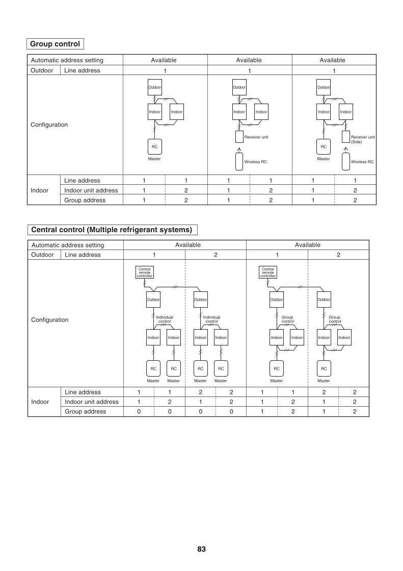
83
Automatic address setting
Group control
Configuration
Outdoor Line address 1 1 1
Line address 1 1 1 1 1 1
Indoor Indoor unit address 1 2 1 2 1 2
Group address 1 2 1 2 1 2
Receiver unit(Side)
Wireless RC.
Receiver unit
Wireless RC.
Outdoor
Indoor
RC
Master
Indoor
Outdoor
Indoor Indoor
Outdoor
Indoor
RC
Master
Indoor
Available Available Available
Central control (Multiple refrigerant systems)
Automatic address setting
Configuration
Outdoor Line address 1 2 1 2
Line address 1 1 2 2 1 1 2 2
Indoor Indoor unit address 1 2 1 2 1 2 1 2
Group address 0 0 0 0 1 2 1 2
Outdoor
Indoor Indoor
RC
Master
RC
Master
Centralremote
controller
Individualcontrol
Outdoor
Indoor Indoor
RC
Master
RC
Master
Individualcontrol
Outdoor
Indoor Indoor
RC
Master
Centralremote
controller
Groupcontrol
Outdoor
Indoor Indoor
RC
Master
Groupcontrol
Available Available
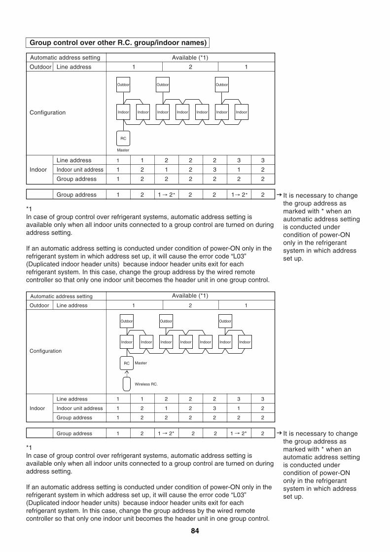
84
Group control over other R.C. group/indoor names)
Outdoor
Indoor Indoor
RC
Master
Outdoor
Indoor Indoor Indoor Indoor
Outdoor
Indoor
Outdoor
Indoor Indoor
RC Master
Wireless RC.
Outdoor
Indoor Indoor Indoor Indoor
Outdoor
Indoor
*1In case of group control over refrigerant systems, automatic address setting is available only when all indoor units connected to a group control are turned on during address setting.
If an automatic address setting is conducted under condition of power-ON only in the refrigerant system in which address set up, it will cause the error code “L03” (Duplicated indoor header units) because indoor header units exit for each refrigerant system. In this case, change the group address by the wired remote controller so that only one indoor unit becomes the header unit in one group control.
It is necessary to change the group address as marked with * when an automatic address setting is conducted under condition of power-ON only in the refrigerant system in which address set up.
Automatic address setting Available (*1)
Available (*1)
Outdoor
Configuration
Line address 1 2 1
Line address 1 1 2 2 2 3 3
Indoor Indoor unit address 1 2 1 2 3 1 2
Group address 1 2 2 2 2 2 2
Group address 1 2 2 21 2* 1 2* 2
Automatic address setting
Configuration
Outdoor Line address 1 2 1
Line address 1 1 2 2 2 3 3
Indoor Indoor unit address 1 2 1 2 3 1 2
Group address 1 2 2 2 2 2 2
Group address 1 2 1 2* 2 2 1 2* 2
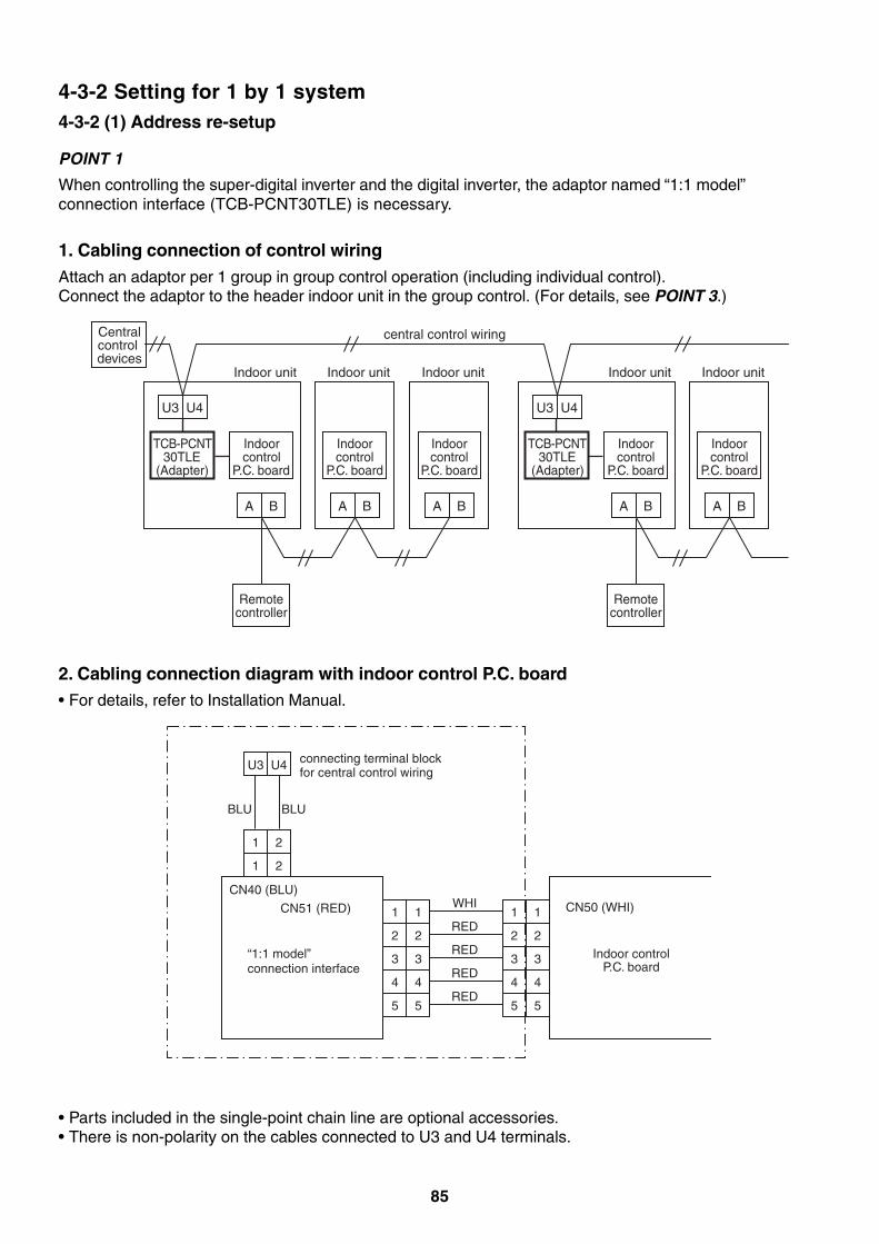
85
4-3-2 Setting for 1 by 1 system4-3-2 (1) Address re-setup
POINT 1
When controlling the super-digital inverter and the digital inverter, the adaptor named “1:1 model”connection interface (TCB-PCNT30TLE) is necessary.
1. Cabling connection of control wiringAttach an adaptor per 1 group in group control operation (including individual control).Connect the adaptor to the header indoor unit in the group control. (For details, see POINT 3.)
2. Cabling connection diagram with indoor control P.C. board• For details, refer to Installation Manual.
• Parts included in the single-point chain line are optional accessories.• There is non-polarity on the cables connected to U3 and U4 terminals.
Centralcontrol devices
U3
TCB-PCNT 30TLE
(Adapter)
TCB-PCNT 30TLE
(Adapter).C. board
Remotecontroller
U4
Indoor unit
A B
Indoorcontrol
Indoorcontrol
PP .C. board
Indoor unit
A B
U3
Indoorcontrol
P.C. board
Remotecontroller
U4
Indoor unit
A B
Indoorcontrol
P.C. board
Indoor unit
A B
Indoorcontrol
P.C. board
Indoor unit
central control wiring
A B
U3 U4
1 2
1 1 1 1
BLU BLU
connecting terminal block for central control wiring
CN40 (BLU)
CN51 (RED)
“1:1 model”connection interface
CN50 (WHI)
Indoor controlP.C. board
WHI
2 2 2 2RED
3 3 3 3RED
4 4 4 4RED
5 5 5 5RED
1 2
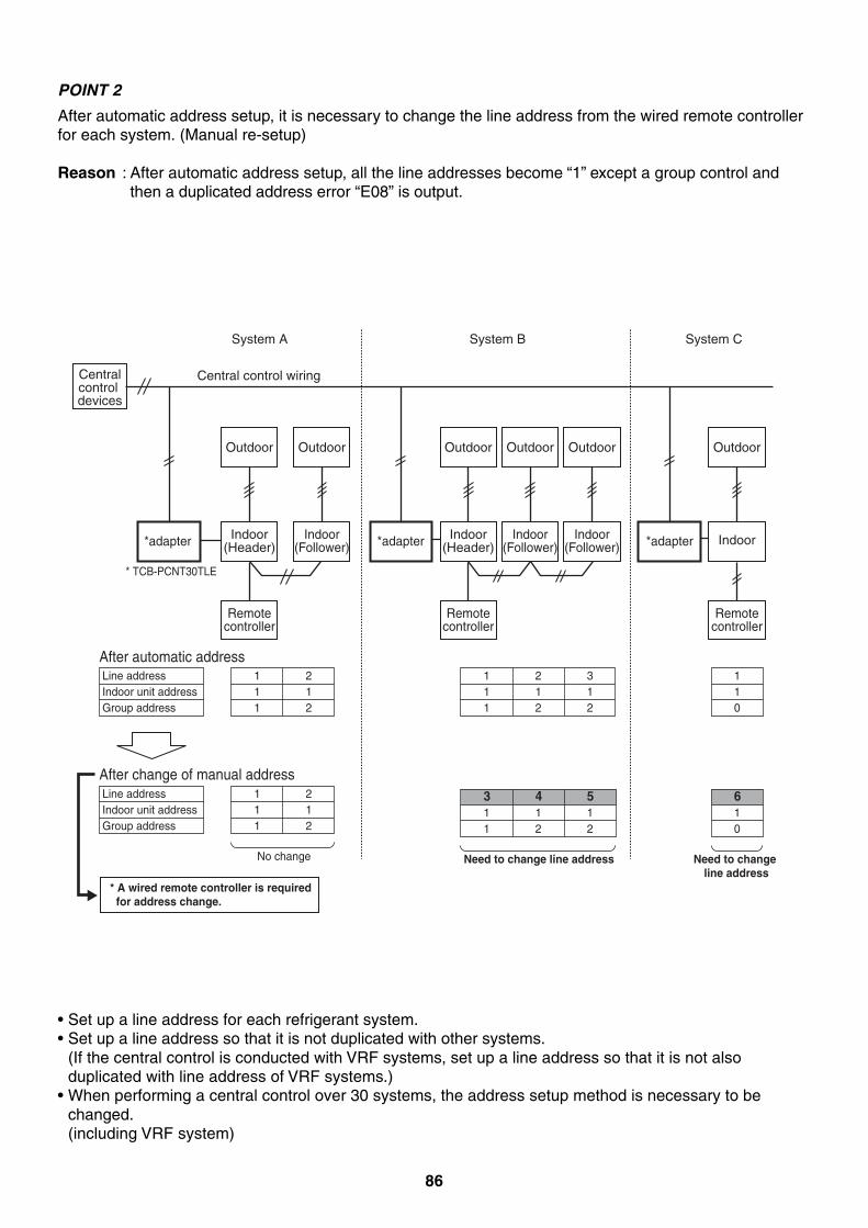
86
POINT 2
After automatic address setup, it is necessary to change the line address from the wired remote controllerfor each system. (Manual re-setup)
Reason : After automatic address setup, all the line addresses become “1” except a group control andthen a duplicated address error “E08” is output.
• Set up a line address for each refrigerant system.• Set up a line address so that it is not duplicated with other systems.
(If the central control is conducted with VRF systems, set up a line address so that it is not alsoduplicated with line address of VRF systems.)
• When performing a central control over 30 systems, the address setup method is necessary to bechanged.(including VRF system)
*adapter *adapter *adapter
Centralcontrol devices
Central control wiring
System A System B System C
Outdoor
Indoor(Header)
Remotecontroller
* TCB-PCNT30TLE
Outdoor
Indoor(Follower)
Outdoor
Indoor(Header)
Remotecontroller
Outdoor
Indoor(Follower)
Outdoor
Indoor(Follower)
Outdoor
Indoor
Remotecontroller
After automatic address
After change of manual address
Line addressIndoor unit addressGroup address
111
212
* A wired remote controller is required for address change.
No change
Line addressIndoor unit addressGroup address
111
212
111
212
312
Need to change line address
311
412
512
110
Need to change line address
610
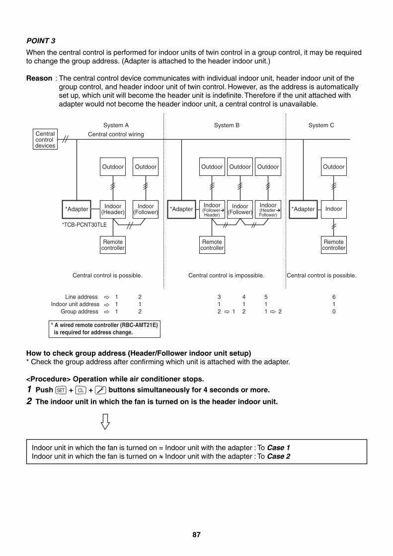
87
POINT 3
When the central control is performed for indoor units of twin control in a group control, it may be requiredto change the group address. (Adapter is attached to the header indoor unit.)
Reason : The central control device communicates with individual indoor unit, header indoor unit of thegroup control, and header indoor unit of twin control. However, as the address is automaticallyset up, which unit will become the header unit is indefinite. Therefore if the unit attached withadapter would not become the header indoor unit, a central control is unavailable.
How to check group address (Header/Follower indoor unit setup)* Check the group address after confirming which unit is attached with the adapter.
<Procedure> Operation while air conditioner stops.1 Push SET + CL + buttons simultaneously for 4 seconds or more.
2 The indoor unit in which the fan is turned on is the header indoor unit.
Indoor unit in which the fan is turned on = Indoor unit with the adapter : To Case 1Indoor unit in which the fan is turned on = Indoor unit with the adapter : To Case 2
*Adapter
Centralcontrol devices
Central control wiring
System A System B System C
Outdoor
*TCB-PCNT30TLE
Indoor(Header)
Remotecontroller
Outdoor
Indoor(Follower) *Adapter
Outdoor
Indoor(Follower Header)
Remotecontroller
Outdoor
Indoor(Follower)
Outdoor
Indoor(Header Follower)
*Adapter
Outdoor
Indoor
Remotecontroller
Line addressIndoor unit address
Group address
111
212
312
4121 2
511
610
Central control is possible. Central control is possible.Central control is impossible.
* A wired remote controller (RBC-AMT21E) is required for address change.
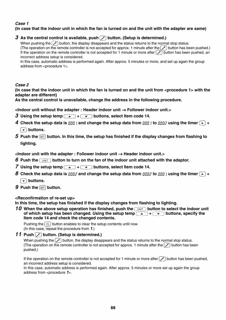
88
Case 1(In case that the indoor unit in which the fan is turned on and the unit with the adapter are same)
3 As the central control is available, push button. (Setup is determined.)When pushing the button, the display disappears and the status returns to the normal stop status.(The operation on the remote controller is not accepted for approx. 1 minute after the button has been pushed.)If the operation on the remote controller is not accepted for 1 minute or more after button has been pushed, anincorrect address setup is considered.In this case, automatic address is performed again. After approx. 5 minutes or more, and set up again the groupaddress from <procedure 1>.
Case 2(In case that the indoor unit in which the fan is turned on and the unit from <procedure 1> with theadapter are different)As the central control is unavailable, change the address in the following procedure.
<Indoor unit without the adapter : Header indoor unit →→→→→ Follower indoor unit.>3 Using the setup temp + buttons, select Item code 14.
4 Check the setup data is and change the setup data from to using the timer +
buttons.
5 Push the SET button. In this time, the setup has finished if the display changes from flashing to
lighting.
<Indoor unit with the adapter : Follower indoor unit →→→→→ Header indoor unit.>6 Push the UNIT button to turn on the fan of the indoor unit attached with the adaptor.
7 Using the setup temp + buttons, select Item code 14.
8 Check the setup data is and change the setup data from to using the timer +
buttons.
9 Push the SET button.
<Reconfirmation of re-set up>In this time, the setup has finished if the display changes from flashing to lighting.10 When the above setup operation has finished, push the UNIT button to select the indoor unit
of which setup has been changed. Using the setup temp + buttons, specify theItem code 14 and check the changed contents.Pushing the CL button enables to clear the setup contents until now.(In this case, repeat the procedure from 1.)
11 Push button. (Setup is determined.)When pushing the button, the display disappears and the status returns to the normal stop status.(The operation on the remote controller is not accepted for approx. 1 minute after the button has beenpushed.)
If the operation on the remote controller is not accepted for 1 minute or more after button has been pushed,an incorrect address setup is considered.In this case, automatic address is performed again. After approx. 5 minutes or more set up again the groupaddress from <procedure 1>.
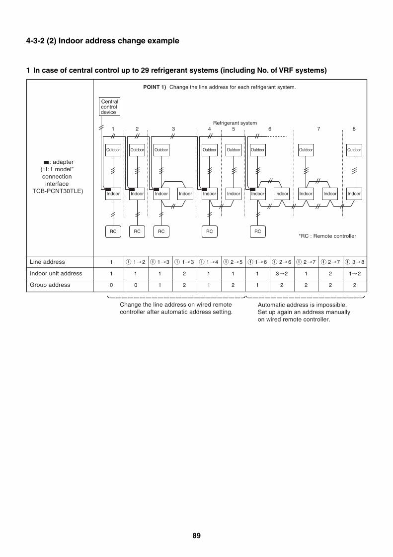
89
1 In case of central control up to 29 refrigerant systems (including No. of VRF systems)
Line address
: adapter (“1:1 model” connection interface
TCB-PCNT30TLE)
1 1 2 1 3 1 3 1 4 2 5 1 6 2 6 2 7 2 7 3 8
Indoor unit address 1 1 1 2 1 1 1 3 2 1 2 1 2
2Group address 0 0 1 2 1 2 1 2 2 2
Automatic address is impossible.Set up again an address manuallyon wired remote controller.
Change the line address on wired remote controller after automatic address setting.
POINT 1) Change the line address for each refrigerant system.
Centralcontrol device
Outdoor
Indoor
1Refrigerant system
RC
Outdoor
Indoor
2
RC
Outdoor
Indoor
3
RC
Indoor
Outdoor
Indoor
4
RC
Outdoor
Indoor
5
Outdoor
Indoor
6
RC
Indoor
Outdoor
Indoor
7
Indoor
Outdoor
Indoor
8
*RC : Remote controller
4-3-2 (2) Indoor address change example
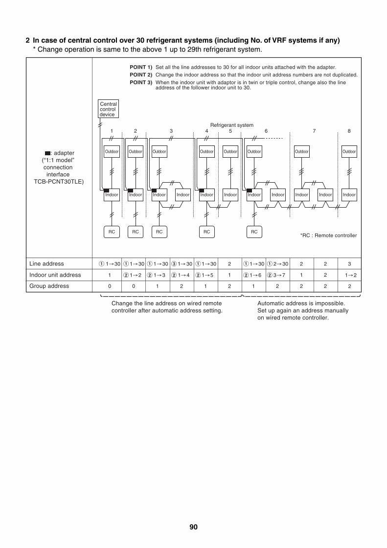
90
2 In case of central control over 30 refrigerant systems (including No. of VRF systems if any)* Change operation is same to the above 1 up to 29th refrigerant system.
Line address 1 30 1 30 1 30 1 30 1 30 2
1
1 30 2 30 2
1
2
2
3
Indoor unit address 1 1 2
Group address 0 0 1 2 1 2 1 2 2 2
Automatic address is impossible.Set up again an address manuallyon wired remote controller.
Change the line address on wired remote controller after automatic address setting.
POINT 1) Set all the line addresses to 30 for all indoor units attached with the adapter.
POINT 2) Change the indoor address so that the indoor unit address numbers are not duplicated.
POINT 3) When the indoor unit with adaptor is in twin or triple control, change also the lineaddress of the follower indoor unit to 30.
Centralcontrol device
Outdoor
Indoor
1Refrigerant system
RC
Outdoor
Indoor
2
RC
Outdoor
Indoor
3
RC
Indoor
Outdoor
Indoor
4
RC
Outdoor
Indoor
5
Outdoor
Indoor
6
RC
Indoor
Outdoor
Indoor
7
Indoor
Outdoor
Indoor
8
: adapter (“1:1 model” connection interface
TCB-PCNT30TLE)
1 5 1 6 3 7 1 2
2
1 3 1 4
*RC : Remote controller
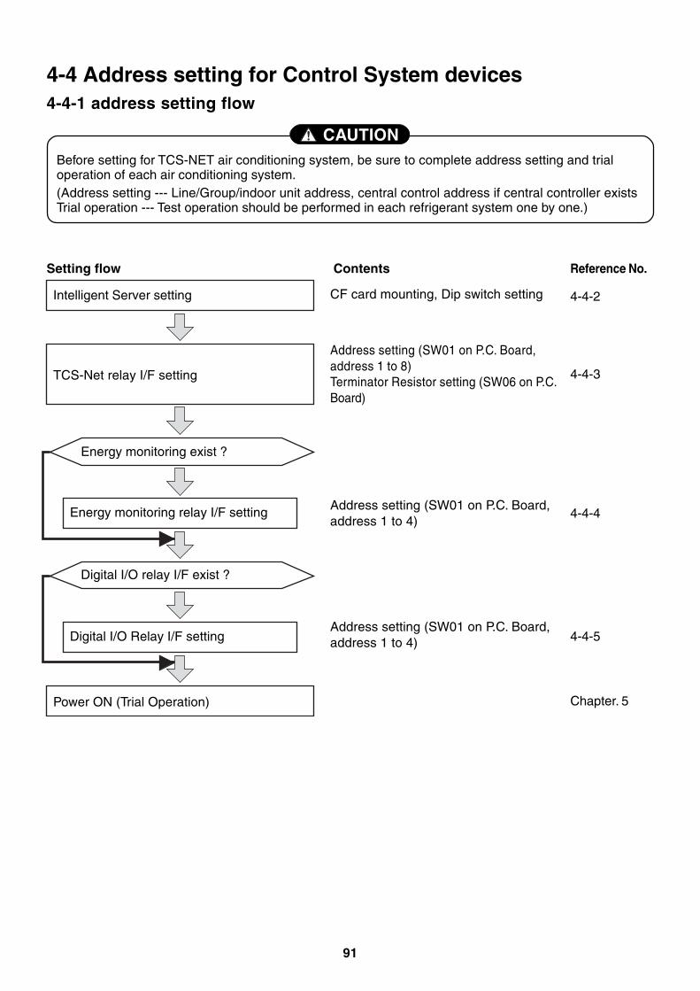
91
Before setting for TCS-NET air conditioning system, be sure to complete address setting and trialoperation of each air conditioning system.(Address setting --- Line/Group/indoor unit address, central control address if central controller existsTrial operation --- Test operation should be performed in each refrigerant system one by one.)
CAUTION
4-4 Address setting for Control System devices4-4-1 address setting flow
Setting flow
Intelligent Server setting
Contents Reference No.
TCS-Net relay I/F setting
Energy monitoring exist ?
CF card mounting, Dip switch setting
Address setting (SW01 on P.C. Board,address 1 to 8)Terminator Resistor setting (SW06 on P.C.Board)
Address setting (SW01 on P.C. Board,address 1 to 4)
Address setting (SW01 on P.C. Board,address 1 to 4)
4-4-2
Energy monitoring relay I/F setting
Digital I/O relay I/F exist ?
Digital I/O Relay I/F setting
Power ON (Trial Operation)
4-4-3
4-4-4
4-4-5
Chapter. 5
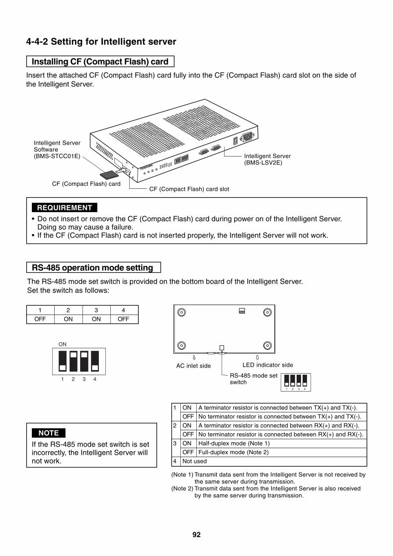
92
4-4-2 Setting for Intelligent server
Installing CF (Compact Flash) card
RS-485 operation mode setting
• Do not insert or remove the CF (Compact Flash) card during power on of the Intelligent Server.Doing so may cause a failure.
• If the CF (Compact Flash) card is not inserted properly, the Intelligent Server will not work.
REQUIREMENT
Insert the attached CF (Compact Flash) card fully into the CF (Compact Flash) card slot on the side ofthe Intelligent Server.
CF (Compact Flash) cardCF (Compact Flash) card slot
1
ON
2 3 4
1 2 3 4
OFF ON ON OFF
1 2 3 4
RS-485 mode setswitch
AC inlet side LED indicator side
The RS-485 mode set switch is provided on the bottom board of the Intelligent Server.Set the switch as follows:
If the RS-485 mode set switch is setincorrectly, the Intelligent Server willnot work.
NOTE
1
2
3
4 Not used
(Note 1) Transmit data sent from the Intelligent Server is not received bythe same server during transmission.
(Note 2) Transmit data sent from the Intelligent Server is also receivedby the same server during transmission.
ON
OFF
ON
OFF
ON
OFF
A terminator resistor is connected between TX(+) and TX(-).
No terminator resistor is connected between TX(+) and TX(-).
A terminator resistor is connected between RX(+) and RX(-).
No terminator resistor is connected between RX(+) and RX(-).
Half-duplex mode (Note 1)
Full-duplex mode (Note 2)
Intelligent ServerSoftware(BMS-STCC01E) Intelligent Server
(BMS-LSV2E)
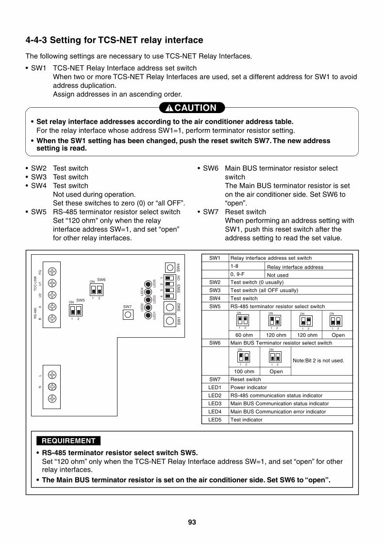
93
4-4-3 Setting for TCS-NET relay interface
1
ON SW5
2
1
ON SW6
SW7
2
1 ON
SW
3S
W4
SW
2S
W1
23
4LED
4
FG
U1
U2
AB
LN
RS
-485
TC
C-L
INK
LED
2
LED
5LE
D3
LED
1
• SW2 Test switch• SW3 Test switch• SW4 Test switch
Not used during operation.Set these switches to zero (0) or “all OFF”.
• SW5 RS-485 terminator resistor select switchSet “120 ohm" only when the relayinterface address SW=1, and set “open”for other relay interfaces.
CAUTION• Set relay interface addresses according to the air conditioner address table.
For the relay interface whose address SW1=1, perform terminator resistor setting.
• When the SW1 setting has been changed, push the reset switch SW7. The new addresssetting is read.
The following settings are necessary to use TCS-NET Relay Interfaces.
• SW1 TCS-NET Relay Interface address set switchWhen two or more TCS-NET Relay Interfaces are used, set a different address for SW1 to avoidaddress duplication.Assign addresses in an ascending order.
• RS-485 terminator resistor select switch SW5.Set “120 ohm” only when the TCS-NET Relay Interface address SW=1, and set “open” for otherrelay interfaces.
• The Main BUS terminator resistor is set on the air conditioner side. Set SW6 to “open”.
REQUIREMENT
• SW6 Main BUS terminator resistor selectswitchThe Main BUS terminator resistor is seton the air conditioner side. Set SW6 to“open”.
• SW7 Reset switchWhen performing an address setting withSW1, push this reset switch after theaddress setting to read the set value.
SW1
SW2
SW3
SW4
SW5
SW6
SW7
LED1
LED2
LED3
LED4
LED5
Relay interface address set switch
1-8
0, 9-F
Test switch (0 usually)
Test switch (all OFF usually)
Test switch
RS-485 terminator resistor select switch
Main BUS Terminator resistor select switch
Reset switch
Power indicator
RS-485 communication status indicator
Main BUS Communication status indicator
Main BUS Communication error indicator
Test indicator
Relay interface address
Not used
Note:Bit 2 is not used.
60 ohm 120 ohm 120 ohm Open
100 ohm Open
1
ON
2 1
ON
2 1
ON
2 1
ON
2
1
ON
2 1
ON
2
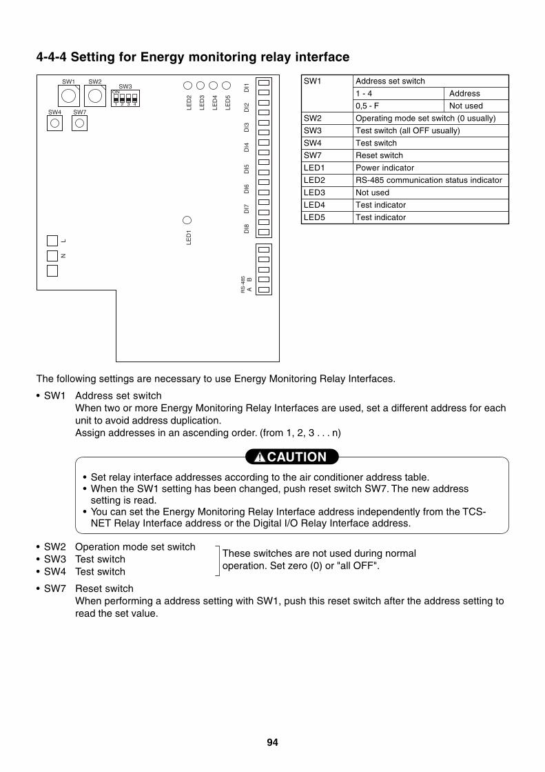
94
4-4-4 Setting for Energy monitoring relay interface
ON
SW1 SW2SW3
LED
2
LED
3
LED
4
LED
5
LED
1
SW4 SW71 2 3 4
DI1
DI2
DI3
DI4
DI5
DI6
DI7
DI8
NL
BARS
-485
• SW2 Operation mode set switch• SW3 Test switch• SW4 Test switch
• SW7 Reset switchWhen performing a address setting with SW1, push this reset switch after the address setting toread the set value.
CAUTION
• Set relay interface addresses according to the air conditioner address table.• When the SW1 setting has been changed, push reset switch SW7. The new address
setting is read.• You can set the Energy Monitoring Relay Interface address independently from the TCS-
NET Relay Interface address or the Digital I/O Relay Interface address.
The following settings are necessary to use Energy Monitoring Relay Interfaces.
• SW1 Address set switchWhen two or more Energy Monitoring Relay Interfaces are used, set a different address for eachunit to avoid address duplication.Assign addresses in an ascending order. (from 1, 2, 3 . . . n)
These switches are not used during normaloperation. Set zero (0) or "all OFF".
SW1
SW2
SW3
SW4
SW7
LED1
LED2
LED3
LED4
LED5
Address set switch
1 - 4 Address
0,5 - F Not used
Operating mode set switch (0 usually)
Test switch (all OFF usually)
Test switch
Reset switch
Power indicator
RS-485 communication status indicator
Not used
Test indicator
Test indicator
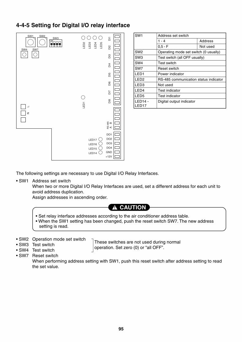
95
4-4-5 Setting for Digital I/O relay interface
ON
SW1 SW2SW3
LED
2
LED
3
LED
4
LED
5
LED
1
LED17
LED16
LED15
LED14
SW4 SW71 2 3 4
DI1
DI2
DI3
DI4
DI5
DI6
DI7
DI8
NL
B
DO1
DO2
DO3
DO4
GND
+12V
ARS
-485
SW1
SW2
SW3
SW4
SW7
LED1
LED2
LED3
LED4
LED5
LED14 -LED17
Address set switch
1 - 4 Address
0,5 - F Not used
Operating mode set switch (0 usually)
Test switch (all OFF usually)
Test switch
Reset switch
Power indicator
RS-485 communication status indicator
Not used
Test indicator
Test indicator
Digital output indicator
• Set relay interface addresses according to the air conditioner address table.• When the SW1 setting has been changed, push the reset switch SW7. The new address
setting is read.
CAUTION
The following settings are necessary to use Digital I/O Relay Interfaces.
• SW1 Address set switchWhen two or more Digital I/O Relay Interfaces are used, set a different address for each unit toavoid address duplication.Assign addresses in ascending order.
• SW2 Operation mode set switch• SW3 Test switch• SW4 Test switch• SW7 Reset switch
When performing address setting with SW1, push this reset switch after address setting to readthe set value.
These switches are not used during normaloperation. Set zero (0) or “all OFF”.

96
97
5
TRIAL OPERATION
5-1 Trial operation5-2 Air conditioning control system troubleshooting
5-2-1 Faults of air conditioner5-2-2 Faults of air conditioning control system
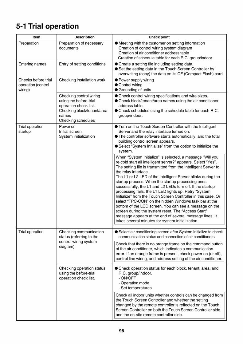
98
5-1 Trial operation
Preparation
Entering names
Checks before trialoperation (controlwiring)
Trial operationstartup
Item Description
Preparation of necessarydocuments
Entry of setting conditions
Checking installation work
Checking control wiringusing the before-trialoperation check list.Checking block/tenant/areanamesChecking schedules
Power onInitial screenSystem initialization
Check point
● Meeting with the customer on setting informationCreation of control wiring system diagramCreation of air conditioner address tableCreation of schedule table for each R.C. group/indoor
● Create a setting file including setting data.● Set the setting data in the Touch Screen Controller by
overwriting (copy) the data on its CF (Compact Flash) card.
● Power supply wiring● Control wiring● Grounding of units
● Check control wiring specifications and wire sizes.● Check block/tenant/area names using the air conditioner
address table.● Check schedules using the schedule table for each R.C.
group/indoor.
● Turn on the Touch Screen Controller with the IntelligentServer and the relay interface turned on.
● The controller software starts automatically, and the totalbuilding control screen appears.
● Select “System Initialize” from the option to initialize thesystem.
When “System Initialize” is selected, a message “Will youre-cold start all intelligent server?” appears. Select “Yes”.The setting file is transmitted from the Intelligent Server tothe relay interface.The L1 or L2 LED of the Intelligent Server blinks during thestartup process. When the startup processing endssuccessfully, the L1 and L2 LEDs turn off. If the startupprocessing fails, the L1 LED lights up. Retry “SystemInitialize” from the Touch Screen Controller in this case. Orselect “TPC-CON” on the hidden Windows task bar at thebottom of the LCD screen. You can see a message on thescreen during the system reset. The “Access Start”message appears at the end of several message lines. Ittakes several minutes for system initialization.
Trial operation Checking communicationstatus (referring to thecontrol wiring systemdiagram)
Checking operation statususing the before-trialoperation check list.
● Select air conditioning screen after System Initialize to checkcommunication status and connection of air conditioners.
Check that there is no orange frame on the command buttonof the air conditioner, which indicates a communicationerror. If an orange frame is present, check power on (or off),control line wiring, and address setting of the air conditioner.
● Check operation status for each block, tenant, area, andR.C. group/indoor.- ON/OFF- Operation mode- Set temperatures
Check all indoor units whether controls can be changed fromthe Touch Screen Controller and whether the settingchanged by the remote controller is reflected on the TouchScreen Controller on both the Touch Screen Controller sideand the on-site remote controller side.
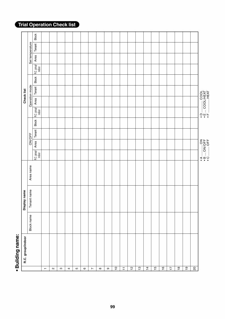
99
Trial Operation Check list
• Bu
ildin
g n
ame:
• A
......
......
.ON
• B
....O
N/O
FF
• C
......
.....
OF
F
• D
......
......
..C
OO
L•
E...
CO
OL
/HE
AT
• F
......
......
....H
EAT
Set
tem
pera
ture
Tena
ntB
lock
1 2 3 4 5 6 7 8 9 10 11 12 13 14 15 16 17 18 19 20
R.C
. g
rou
p/i
nd
oo
r
Blo
ck n
ame
Ten
ant
nam
eA
rea
nam
e
R.C.
grou
p/ind
oor
Are
a
Dis
pla
y n
ame
Tena
ntB
lock
R.C.
grou
p/ind
oor
Are
aTe
nant
Blo
ckR.
C. gr
oup/
indoo
r
ON
/OF
FO
pera
tion
mod
e
Are
a
Ch
eck
list
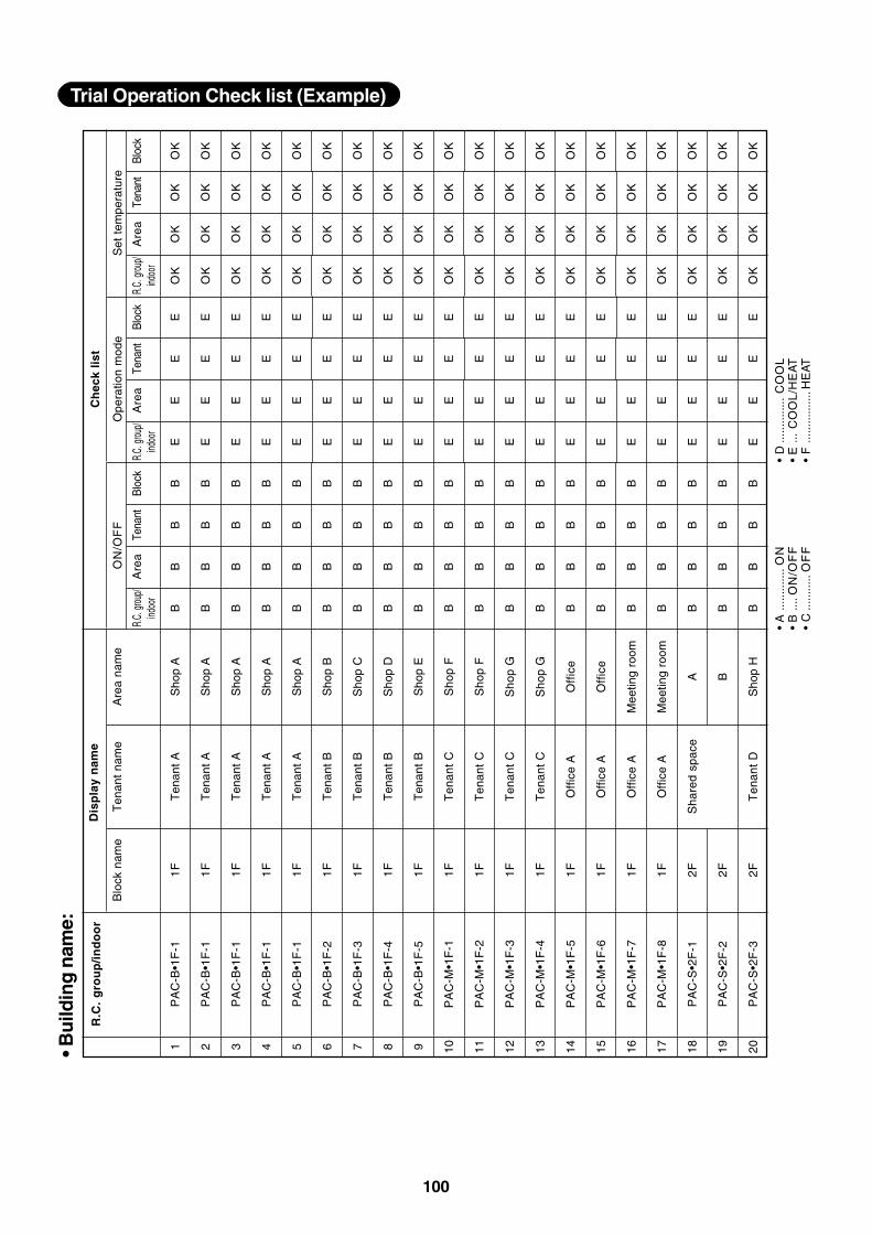
100
Trial Operation Check list (Example)
1 2 3 4 5 6 7 8 9 10 11 12 13 14 15 16 17 18 19 20
R.C
. g
rou
p/i
nd
oo
r
PA
C-B
•1F
-1
PA
C-B
•1F
-1
PA
C-B
•1F
-1
PA
C-B
•1F
-1
PA
C-B
•1F
-1
PA
C-B
•1F
-2
PA
C-B
•1F
-3
PA
C-B
•1F
-4
PA
C-B
•1F
-5
PA
C-M
•1F
-1
PA
C-M
•1F
-2
PA
C-M
•1F
-3
PA
C-M
•1F
-4
PA
C-M
•1F
-5
PA
C-M
•1F
-6
PA
C-M
•1F
-7
PA
C-M
•1F
-8
PA
C-S
•2F
-1
PA
C-S
•2F
-2
PA
C-S
•2F
-3
Blo
ck n
ame
1F
1F
1F
1F
1F
1F
1F
1F
1F
1F
1F
1F
1F
1F
1F
1F
1F
2F
2F
2F
Ten
ant
nam
e
Ten
ant
A
Ten
ant
A
Ten
ant
A
Ten
ant
A
Ten
ant
A
Ten
ant
B
Ten
ant
B
Ten
ant
B
Ten
ant
B
Ten
ant
C
Ten
ant
C
Ten
ant
C
Ten
ant
C
Off
ice
A
Off
ice
A
Off
ice
A
Off
ice
A
Sha
red
spac
e
Ten
ant
D
Are
a na
me
Sho
p A
Sho
p A
Sho
p A
Sho
p A
Sho
p A
Sho
p B
Sho
p C
Sho
p D
Sho
p E
Sho
p F
Sho
p F
Sho
p G
Sho
p G
Off
ice
Off
ice
Mee
ting
room
Mee
ting
room
A B
Sho
p H
R.C.
grou
p/ind
oor
B B B B B B B B B B B B B B B B B B B B
Are
a
B B B B B B B B B B B B B B B B B B B B
Tena
nt
B B B B B B B B B B B B B B B B B B B B
Blo
ck B B B B B B B B B B B B B B B B B B B B
R.C.
grou
p/ind
oor
E E E E E E E E E E E E E E E E E E E E
Are
a
E E E E E E E E E E E E E E E E E E E E
Tena
nt
E E E E E E E E E E E E E E E E E E E E
Blo
ck E E E E E E E E E E E E E E E E E E E E
R.C.
grou
p/ind
oor
OK
OK
OK
OK
OK
OK
OK
OK
OK
OK
OK
OK
OK
OK
OK
OK
OK
OK
OK
OK
Are
a
OK
OK
OK
OK
OK
OK
OK
OK
OK
OK
OK
OK
OK
OK
OK
OK
OK
OK
OK
OK
Tena
nt
OK
OK
OK
OK
OK
OK
OK
OK
OK
OK
OK
OK
OK
OK
OK
OK
OK
OK
OK
OK
Blo
ck
OK
OK
OK
OK
OK
OK
OK
OK
OK
OK
OK
OK
OK
OK
OK
OK
OK
OK
OK
OK
• A
......
......
.ON
• B
....O
N/O
FF
• C
......
.....
OF
F
• D
......
......
..C
OO
L•
E...
CO
OL
/HE
AT
• F
......
......
....H
EAT
• Bu
ildin
g n
ame:
Dis
pla
y n
ame
Ch
eck
list
ON
/OF
FO
pera
tion
mod
eS
et t
empe
ratu
re
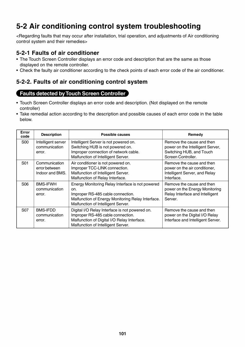
101
5-2 Air conditioning control system troubleshooting<Regarding faults that may occur after installation, trial operation, and adjustments of Air conditioningcontrol system and their remedies>
5-2-1 Faults of air conditioner• The Touch Screen Controller displays an error code and description that are the same as those
displayed on the remote controller.• Check the faulty air conditioner according to the check points of each error code of the air conditioner.
5-2-2. Faults of air conditioning control system
Faults detected by Touch Screen Controller
• Touch Screen Controller displays an error code and description. (Not displayed on the remotecontroller)
• Take remedial action according to the description and possible causes of each error code in the tablebelow.
S00
S01
S06
S07
Errorcode Description
Intelligent servercommunicationerror.
Communicationerror betweenIndoor and BMS.
BMS-IFWHcommunicationerror.
BMS-IFDDcommunicationerror.
Possible causes
Intelligent Server is not powered on.Switching HUB is not powered on.Improper connection of network cable.Malfunction of Intelligent Server.
Air conditioner is not powered on.Improper TCC-LINK connection.Malfunction of Intelligent Server.Malfunction of Relay Interface.
Energy Monitoring Relay Interface is not poweredon.Improper RS-485 cable connection.Malfunction of Energy Monitoring Relay Interface.Malfunction of Intelligent Server.
Digital I/O Relay Interface is not powered on.Improper RS-485 cable connection.Malfunction of Digital I/O Relay Interface.Malfunction of Intelligent Server.
Remedy
Remove the cause and thenpower on the Intelligent Server,Switching HUB, and TouchScreen Controller.
Remove the cause and thenpower on the air conditioner,Intelligent Server, and RelayInterface.
Remove the cause and thenpower on the Energy MonitoringRelay Interface and IntelligentServer.
Remove the cause and thenpower on the Digital I/O RelayInterface and Intelligent Server.
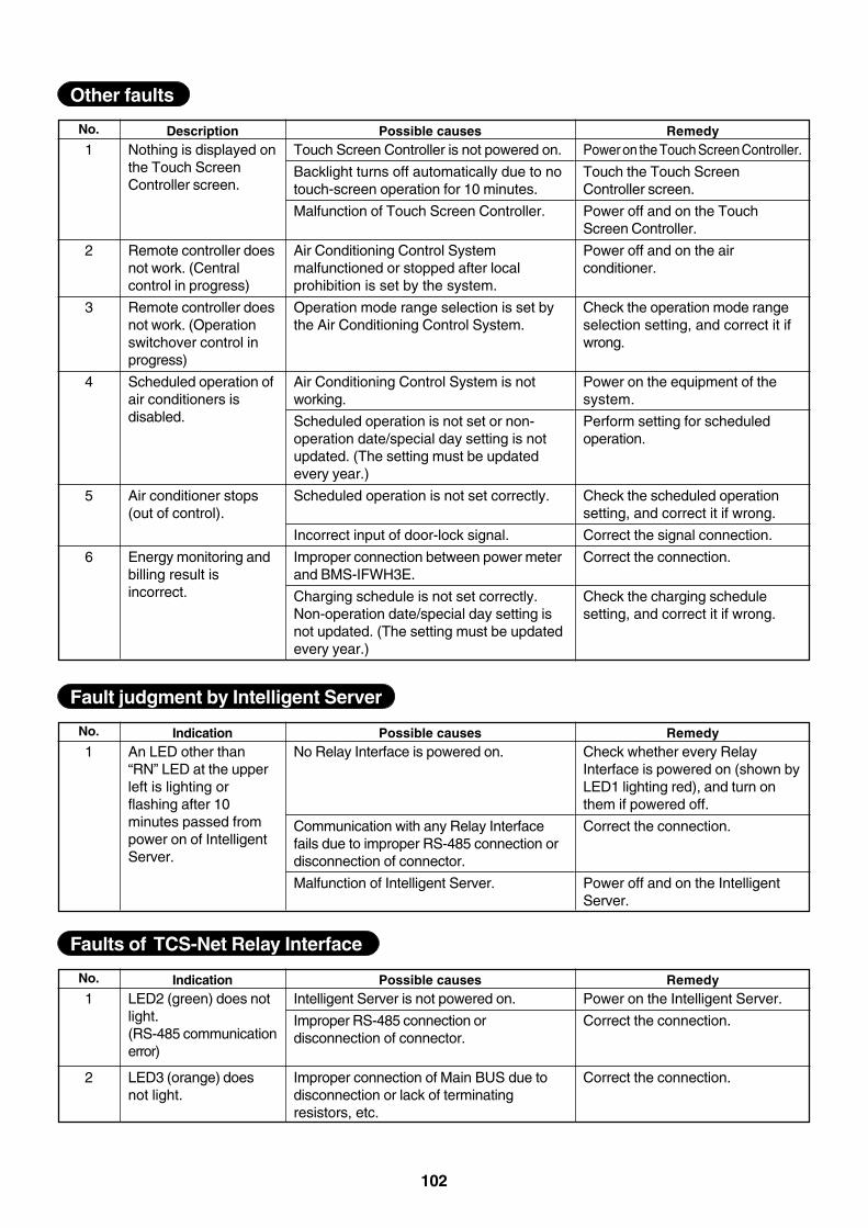
102
1
2
3
4
5
6
No. DescriptionNothing is displayed onthe Touch ScreenController screen.
Remote controller doesnot work. (Centralcontrol in progress)
Remote controller doesnot work. (Operationswitchover control inprogress)
Scheduled operation ofair conditioners isdisabled.
Air conditioner stops(out of control).
Energy monitoring andbilling result isincorrect.
Possible causesTouch Screen Controller is not powered on.
Backlight turns off automatically due to notouch-screen operation for 10 minutes.
Malfunction of Touch Screen Controller.
Air Conditioning Control Systemmalfunctioned or stopped after localprohibition is set by the system.
Operation mode range selection is set bythe Air Conditioning Control System.
Air Conditioning Control System is notworking.
Scheduled operation is not set or non-operation date/special day setting is notupdated. (The setting must be updatedevery year.)
Scheduled operation is not set correctly.
Incorrect input of door-lock signal.
Improper connection between power meterand BMS-IFWH3E.
Charging schedule is not set correctly.Non-operation date/special day setting isnot updated. (The setting must be updatedevery year.)
RemedyPower on the Touch Screen Controller.
Touch the Touch ScreenController screen.
Power off and on the TouchScreen Controller.
Power off and on the airconditioner.
Check the operation mode rangeselection setting, and correct it ifwrong.
Power on the equipment of thesystem.
Perform setting for scheduledoperation.
Check the scheduled operationsetting, and correct it if wrong.
Correct the signal connection.
Correct the connection.
Check the charging schedulesetting, and correct it if wrong.
Other faults
1No. Indication
An LED other than“RN” LED at the upperleft is lighting orflashing after 10minutes passed frompower on of IntelligentServer.
Possible causesNo Relay Interface is powered on.
Communication with any Relay Interfacefails due to improper RS-485 connection ordisconnection of connector.
Malfunction of Intelligent Server.
RemedyCheck whether every RelayInterface is powered on (shown byLED1 lighting red), and turn onthem if powered off.
Correct the connection.
Power off and on the IntelligentServer.
Fault judgment by Intelligent Server
1
2
No. IndicationLED2 (green) does notlight.(RS-485 communicationerror)
LED3 (orange) doesnot light.
Possible causesIntelligent Server is not powered on.
Improper RS-485 connection ordisconnection of connector.
Improper connection of Main BUS due todisconnection or lack of terminatingresistors, etc.
RemedyPower on the Intelligent Server.
Correct the connection.
Correct the connection.
Faults of TCS-Net Relay Interface

103