Embed Size (px)
Citation preview
TensionControl
Systems
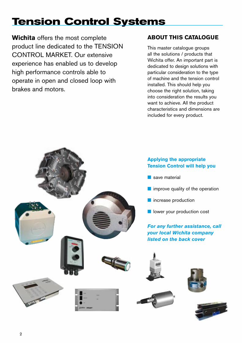
Wichita offers the most complete product line dedicated to the TENSION CONTROL MARKET. Our extensive experience has enabled us to develop high performance controls able to operate in open and closed loop with brakes and motors.
ABOUT THIS CATALOGUE
This master catalogue groups all the solutions / products that Wichita offer. An important part is dedicated to design solutions with particular consideration to the type of machine and the tension control installed. This should help you choose the right solution, taking into consideration the results you want to achieve. All the product characteristics and dimensions are included for every product.
Tension Control Systems
Applying the appropriate Tension Control will help you
n save material
n improve quality of the operation
n increase production
n lower your production cost
For any further assistance, call your local Wichita company listed on the back cover
2
3
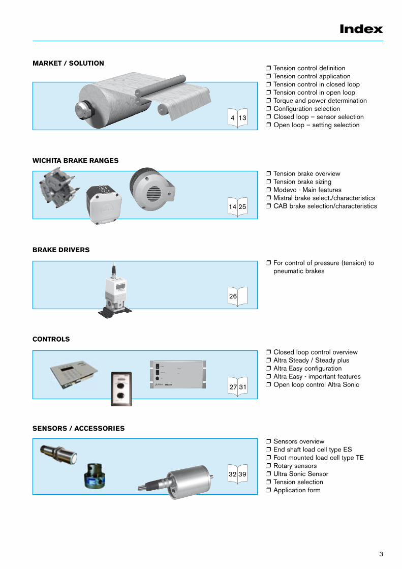
p Tension control definitionp Tension control application p Tension control in closed loopp Tension control in open loopp Torque and power determinationp Configuration selectionp Closed loop – sensor selectionp Open loop – setting selection
p Tension brake overviewp Tension brake sizingp Modevo - Main featuresp Mistral brake select./characteristicsp CAB brake selection/characteristics
p For control of pressure (tension) to pneumatic brakes
p Closed loop control overviewp Altra Steady / Steady plusp Altra Easy configurationp Altra Easy - important featuresp Open loop control Altra Sonic
p Sensors overviewp End shaft load cell type ESp Foot mounted load cell type TEp Rotary sensorsp Ultra Sonic Sensorp Tension selectionp Application form
Index
MARKET / SOLUTION
WICHITA BRAKE RANGES
BRAKE DRIVERS
CONTROLS
SENSORS / ACCESSORIES
26
134
2514
3127
3932
4
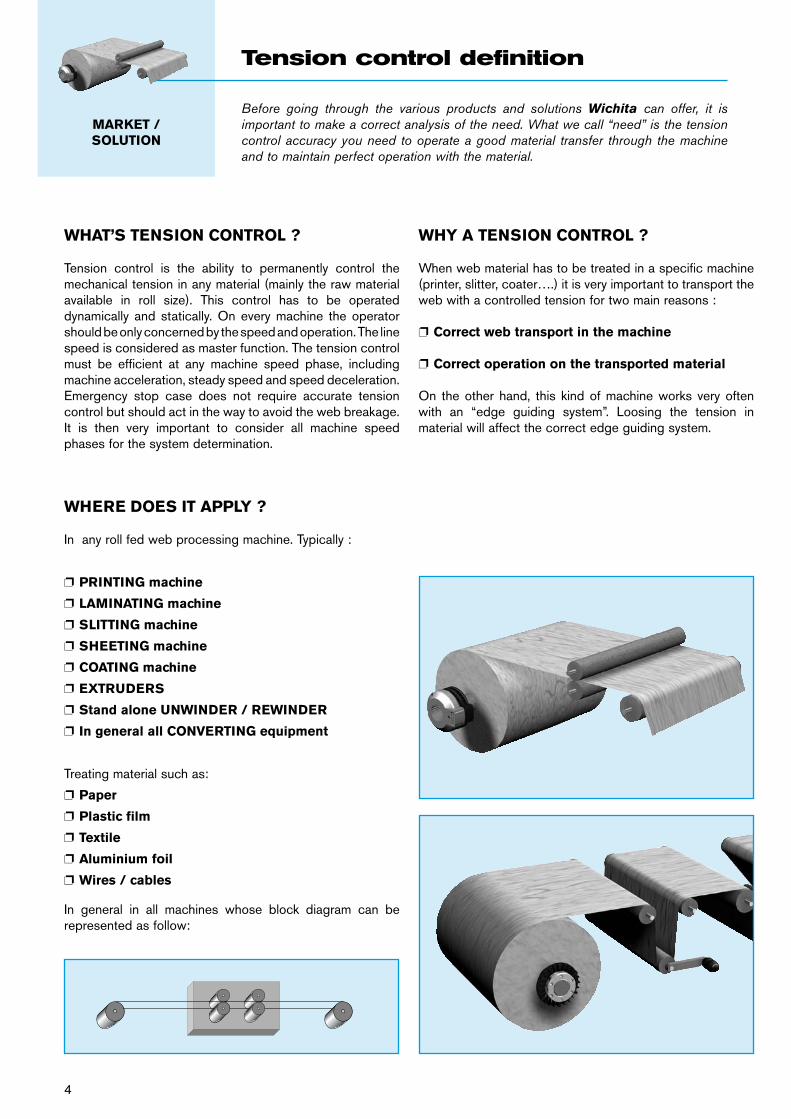
Before going through the various products and solutions Wichita can offer, it is important to make a correct analysis of the need. What we call “need” is the tension control accuracy you need to operate a good material transfer through the machine and to maintain perfect operation with the material.
MARKET /SOLUTION
Tension control definition
WHAT’S TENSION CONTROL ?
Tension control is the ability to permanently control the mechanical tension in any material (mainly the raw material available in roll size). This control has to be operated dynamically and statically. On every machine the operator should be only concerned by the speed and operation. The line speed is considered as master function. The tension control must be efficient at any machine speed phase, including machine acceleration, steady speed and speed deceleration. Emergency stop case does not require accurate tension control but should act in the way to avoid the web breakage. It is then very important to consider all machine speed phases for the system determination.
WHY A TENSION CONTROL ?
When web material has to be treated in a specific machine (printer, slitter, coater….) it is very important to transport the web with a controlled tension for two main reasons :
p Correct web transport in the machine
p Correct operation on the transported material
On the other hand, this kind of machine works very often with an “edge guiding system”. Loosing the tension in material will affect the correct edge guiding system.
WHERE DOES IT APPLY ?
In any roll fed web processing machine. Typically :
p PRINTING machine
p LAMINATING machine
p SLITTING machine
p SHEETING machine
p COATING machine
p EXTRUDERS
p Stand alone UNWINDER / REWINDER
p In general all CONVERTING equipment
Treating material such as:
p Paper
p Plastic film
p Textile
p Aluminium foil
p Wires / cables
In general in all machines whose block diagram can be represented as follow:
5
A D
B C
X Y Z
Zone 1 Zone 2 Zone 3
IMPORTANT CONSIDERATION
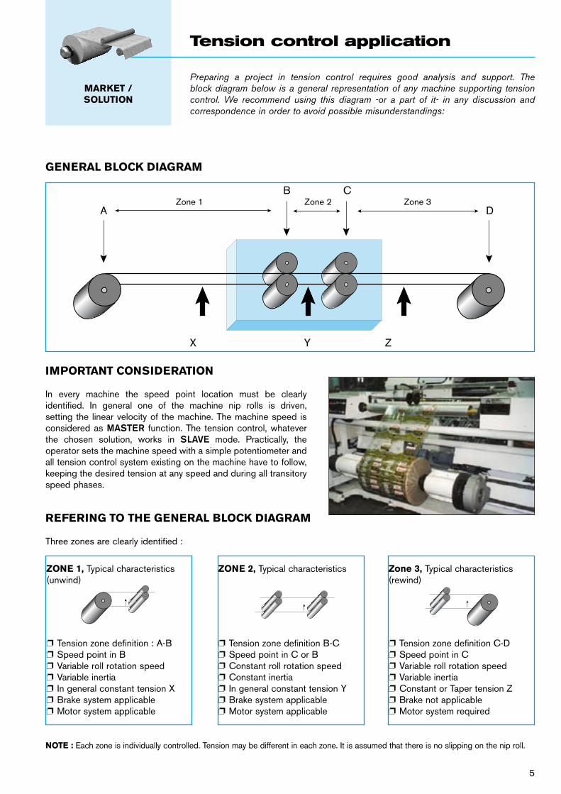
In every machine the speed point location must be clearly identified. In general one of the machine nip rolls is driven, setting the linear velocity of the machine. The machine speed is considered as MASTER function. The tension control, whatever the chosen solution, works in SLAVE mode. Practically, the operator sets the machine speed with a simple potentiometer and all tension control system existing on the machine have to follow, keeping the desired tension at any speed and during all transitory speed phases.
REFERING TO THE GENERAL BLOCK DIAGRAM
Three zones are clearly identified :
ZONE 1, Typical characteristics(unwind)
p Tension zone definition : A-Bp Speed point in Bp Variable roll rotation speedp Variable inertia p In general constant tension Xp Brake system applicable p Motor system applicable
Zone 3, Typical characteristics(rewind)
p Tension zone definition C-Dp Speed point in Cp Variable roll rotation speedp Variable inertiap Constant or Taper tension Zp Brake not applicablep Motor system required
ZONE 2, Typical characteristics
p Tension zone definition B-Cp Speed point in C or Bp Constant roll rotation speedp Constant inertiap In general constant tension Yp Brake system applicablep Motor system applicable
NOTE : Each zone is individually controlled. Tension may be different in each zone. It is assumed that there is no slipping on the nip roll.
Preparing a project in tension control requires good analysis and support. The block diagram below is a general representation of any machine supporting tension control. We recommend using this diagram -or a part of it- in any discussion and correspondence in order to avoid possible misunderstandings:
MARKET /SOLUTION
Tension control application
GENERAL BLOCK DIAGRAM
6
CLOSED LOOP SOLUTION
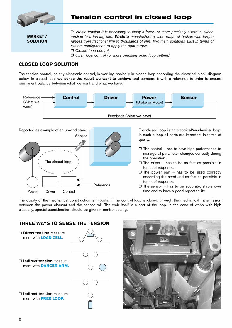
The tension control, as any electronic control, is working basically in closed loop according the electrical block diagram below. In closed loop we sense the result we want to achieve and compare it with a reference in order to ensure permanent balance between what we want and what we have.
Reported as example of an unwind stand The closed loop is an electrical/mechanical loop. In such a loop all parts are important in terms of quality.
p The control – has to have high performance to manage all parameter changes correctly during the operation.
p The driver – has to be as fast as possible in terms of response.
p The power part – has to be sized correctly according the need and as fast as possible in terms of response.
p The sensor – has to be accurate, stable over time and to have a good repeatability.
The quality of the mechanical construction is important. The control loop is closed through the mechanical transmission between the power element and the sensor roll. The web itself is a part of the loop. In the case of webs with high elasticity, special consideration should be given in control setting.
THREE WAYS TO SENSE THE TENSION
Control Driver Power SensorReference(What wewant)
Feedback (What we have)
(Brake or Motor)
The closed loop
Sensor
Power Driver Control
Reference
p Direct tension measure-ment with LOAD CELL.
p Indirect tension measure-ment with DANCER ARM.
p Indirect tension measure-ment with FREE LOOP.
To create tension it is necessary to apply a force -or more precisely a torque- when applied to a turning part. Wichita manufacture a wide range of brakes with torque ranges from fractional Nm to thousands of Nm. Two main solutions exist in terms of system configuration to apply the right torque:p Closed loop control.p Open loop control (or more precisely open loop setting).
MARKET /SOLUTION
Tension control in closed loop
OPEN LOOP SOLUTION
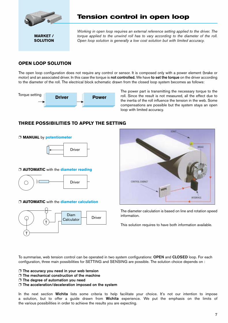
The open loop configuration does not require any control or sensor. It is composed only with a power element (brake or motor) and an associated driver. In this case the torque is not controlled. We have to set the torque on the driver according to the diameter of the roll. The electrical block schematic drawn from the closed loop system becomes as follows:
The power part is transmitting the necessary torque to the roll. Since the result is not measured, all the effect due to the inertia of the roll influence the tension in the web. Some compensations are possible but the system stays an open loop with limited accuracy.
p MANUAL by potentiometer
p AUTOMATIC with the diameter reading
p AUTOMATIC with the diameter calculation
Driver
Driver
DriverDiam
Calculator
T
T
To summarise, web tension control can be operated in two system configurations: OPEN and CLOSED loop. For each configuration, three main possibilities for SETTING and SENSING are possible. The solution choice depends on :
p The accuracy you need in your web tensionp The mechanical construction of the machinep The degree of automation you needp The acceleration/deceleration imposed on the system
In the next section Wichita lists some criteria to help facilitate your choice. It’s not our intention to impose a solution, but to offer a guide drawn from Wichita experience. We put the emphasis on the limits of the various possibilities in order to achieve the results you are expecting.
The diameter calculation is based on line and rotation speed information.
This solution requires to have both information available.
Working in open loop requires an external reference setting applied to the driver. The torque applied to the unwind roll has to vary according to the diameter of the roll. Open loop solution is generally a low cost solution but with limited accuracy.
MARKET /SOLUTION
Tension control in open loop
7
THREE POSSIBILITIES TO APPLY THE SETTING
Torque settingDriver Power
8
“POWER” FROM MOTOR OR BRAKE ?
Based on two parameters :
p Do I need a positive torque or is a negative torque sufficient ?p Which technology is on the machine ?
In the case where the “torque need” calculation shows positive results we are forced to use a motor. Only a motor is able to provide positive torque. It’s typically the case on the rewind stand; on the other hand, the brake solution very often suits the requirements for an unwind stand.
The technology parameter is purely a customer decision. The tension control with motor is today operated with AC motor and flux vector control drive with full power regeneration in the line.
WICHITA offer both solutions with a wide range of products.
TORQUE NEED EVALUATION
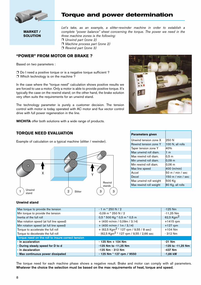
Example of calculation on a typical machine (slitter / rewinder).
Unwind stand
X Y
1 2 3 3SlitterUnwindstand
Rewindstands
Parameters given
Unwind tension zone X 250 NRewind tension zone Y 100 N, all rollsTaper tension zone Y 40%Max unwind roll diam. 1 mMax rewind roll diam. 0,5 mMin unwind roll diam. 0,09 mMin rewind roll diam. 0,06 mMax line speed 400 (m/min)Accel 50 m / min / secDecel 150 m / min / secMax unwind roll weight 500 KgMax rewind roll weight 80 Kg, all rolls
The torque need for each machine phase shows a negative result. Brake and motor can comply with all parameters. Whatever the choice the selection must be based on the max requirements of heat, torque and speed.
Let’s take, as an example, a slitter-rewinder machine in order to establish a complete “power balance” sheet concerning the torque. The power we need in the three machine zones is the following:p Unwind part (zone 2)p Machine process part (zone 2)p Rewind part (zone 3)
MARKET /SOLUTION
Torque and power determination
Max torque to provide the tension - 1 m * 250 N / 2 -125 NmMin torque to provide the tension -0,09 m * 250 N / 2 -11,25 NmInertia of the full roll 0,5 * 500 Kg * 0,5 m * 0,5 m 62,5 Kgm2
Max rotation speed (at full line speed) + (400 m/min / 0,09m / 3.14) +1415 rpmMin rotation speed (at full line speed) + (400 m/min / 1m / 3,14) +127 rpmTorque to accelerate the full roll + (62,5 Kgm2 * 127 rpm / 9,55 / 8 sec) +104 NmTorque to decelerate the full roll - (62,5 Kgm2 * 127 rpm / 9,55 / 2,66 sec - 312 NmTorque need on the roll to insure correct tension- In acceleration - 125 Nm + 104 Nm -21 Nm- During steady speed for D to d -125 Nm to -11,25 Nm -125 to -11,25 Nm- In deceleration -125 Nm - 312 Nm -437 Nm- Max continuous power dissipated - 125 Nm * 127 rpm / 9550 -1,66 kW
250 N100 N
100 N
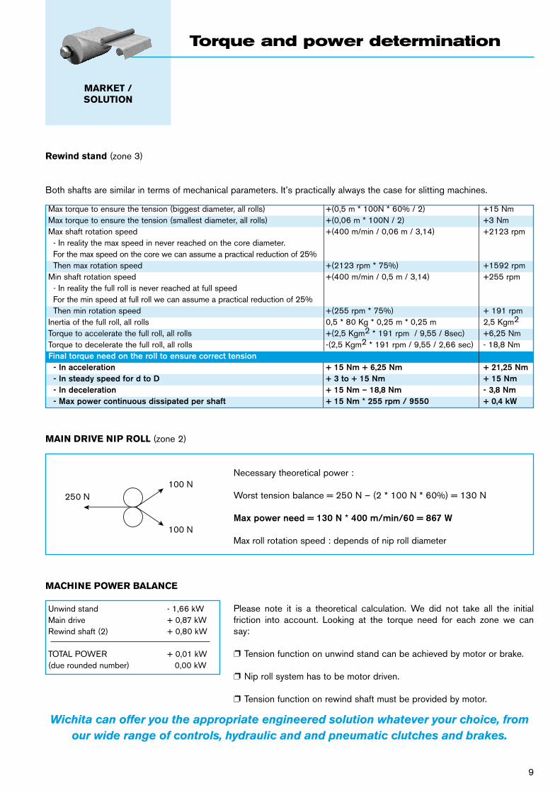
Rewind stand (zone 3)
MAIN DRIVE NIP ROLL (zone 2)
MACHINE POWER BALANCE
Please note it is a theoretical calculation. We did not take all the initial friction into account. Looking at the torque need for each zone we can say:
p Tension function on unwind stand can be achieved by motor or brake.
p Nip roll system has to be motor driven.
p Tension function on rewind shaft must be provided by motor.
Wichita can offer you the appropriate engineered solution whatever your choice, from our wide range of controls, hydraulic and and pneumatic clutches and brakes.
Both shafts are similar in terms of mechanical parameters. It’s practically always the case for slitting machines.
Max torque to ensure the tension (biggest diameter, all rolls) +(0,5 m * 100N * 60% / 2) +15 NmMax torque to ensure the tension (smallest diameter, all rolls) +(0,06 m * 100N / 2) +3 NmMax shaft rotation speed +(400 m/min / 0,06 m / 3,14) +2123 rpm - In reality the max speed in never reached on the core diameter. For the max speed on the core we can assume a practical reduction of 25% Then max rotation speed +(2123 rpm * 75%) +1592 rpmMin shaft rotation speed +(400 m/min / 0,5 m / 3,14) +255 rpm - In reality the full roll is never reached at full speed For the min speed at full roll we can assume a practical reduction of 25% Then min rotation speed +(255 rpm * 75%) + 191 rpmInertia of the full roll, all rolls 0,5 * 80 Kg * 0,25 m * 0,25 m 2,5 Kgm2
Torque to accelerate the full roll, all rolls +(2,5 Kgm2 * 191 rpm / 9,55 / 8sec) +6,25 NmTorque to decelerate the full roll, all rolls -(2,5 Kgm2 * 191 rpm / 9,55 / 2,66 sec) - 18,8 NmFinal torque need on the roll to ensure correct tension - In acceleration + 15 Nm + 6,25 Nm + 21,25 Nm - In steady speed for d to D + 3 to + 15 Nm + 15 Nm - In deceleration + 15 Nm – 18,8 Nm - 3,8 Nm - Max power continuous dissipated per shaft + 15 Nm * 255 rpm / 9550 + 0,4 kW
Unwind stand - 1,66 kWMain drive + 0,87 kWRewind shaft (2) + 0,80 kW
TOTAL POWER + 0,01 kW(due rounded number) 0,00 kW
Necessary theoretical power :
Worst tension balance = 250 N – (2 * 100 N * 60%) = 130 N
Max power need = 130 N * 400 m/min/60 = 867 W
Max roll rotation speed : depends of nip roll diameter
MARKET / SOLUTION
Torque and power determination
9
10
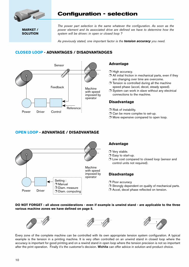
CLOSED LOOP - ADVANTAGES / DISADVANTADGES
OPEN LOOP - ADVANTAGE / DISADVANTAGE
DO NOT FORGET : all above considerations - even if example is unwind stand - are applicable to the three various machine zones we have defined on page 5.
Every zone of the complete machine can be controlled with its own appropriate tension system configuration. A typical example is the tension in a printing machine. It is very often controlled on an unwind stand in closed loop where the accuracy is important for good printing and on a rewind stand in open loop where the tension precision is not so important after the print operation. Finally it’s the customer's decision. Wichita can offer advice in solution and product choice.
Advantage
p High accuracy.p All initial friction in mechanical parts, even if they
are changing over time are overcome.p Tension is controlled during all the machine
speed phase (accel, decel, steady speed).p System can work in slave without any electrical
connections to the machine.
Disadvantage
p Risk of instability.p Can be more complex to set-up.p More expensive compared to open loop.
Advantage
p Very stable.p Easy to start-up.p Low cost compared to closed loop (sensor and
control units not required).
Disadvantage
p Poor accuracyp Strongly dependent on quality of mechanical parts.p Accel, decel phase reflected on tension.
Feedback
Sensor
Power Driver ControlReference
Machinewith speedimposed byoperator
Power Driver
Machinewith speedimposed byoperator
Setting :p Manualp Diam. measurep Diam. computing
The power part selection is the same whatever the configuration. As soon as the power element and its associated drive are defined we have to determine how the system will be driven: in open or closed loop ?
As previously stated, one important factor is the tension accuracy you need.
MARKET /SOLUTION
Configuration - selection
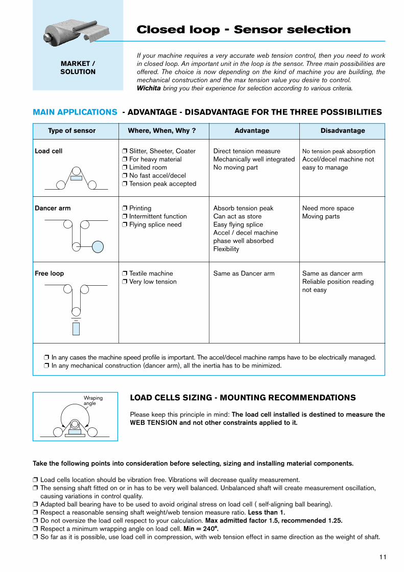
LOAD CELLS SIZING - MOUNTING RECOMMENDATIONS
Please keep this principle in mind: The load cell installed is destined to measure the WEB TENSION and not other constraints applied to it.
Wrapingangle
Type of sensor Where, When, Why ? Advantage Disadvantage
Load cell p Slitter, Sheeter, Coater Direct tension measure No tension peak absorption p For heavy material Mechanically well integrated Accel/decel machine not p Limited room No moving part easy to manage p No fast accel/decel p Tension peak accepted
Dancer arm p Printing Absorb tension peak Need more space p Intermittent function Can act as store Moving parts p Flying splice need Easy flying splice Accel / decel machine phase well absorbed Flexibility
Free loop p Textile machine Same as Dancer arm Same as dancer arm p Very low tension Reliable position reading not easy
MAIN APPLICATIONS - ADVANTAGE - DISADVANTAGE FOR THE THREE POSSIBILITIES
p In any cases the machine speed profile is important. The accel/decel machine ramps have to be electrically managed.p In any mechanical construction (dancer arm), all the inertia has to be minimized.
Take the following points into consideration before selecting, sizing and installing material components.
p Load cells location should be vibration free. Vibrations will decrease quality measurement.p The sensing shaft fitted on or in has to be very well balanced. Unbalanced shaft will create measurement oscillation,
causing variations in control quality.p Adapted ball bearing have to be used to avoid original stress on load cell ( self-aligning ball bearing).p Respect a reasonable sensing shaft weight/web tension measure ratio. Less than 1. p Do not oversize the load cell respect to your calculation. Max admitted factor 1.5, recommended 1.25. p Respect a minimum wrapping angle on load cell. Min = 240°.p So far as it is possible, use load cell in compression, with web tension effect in same direction as the weight of shaft.
If your machine requires a very accurate web tension control, then you need to work in closed loop. An important unit in the loop is the sensor. Three main possibilities are offered. The choice is now depending on the kind of machine you are building, the mechanical construction and the max tension value you desire to control.Wichita bring you their experience for selection according to various criteria.
MARKET /SOLUTION
Closed loop - Sensor selection
11
12
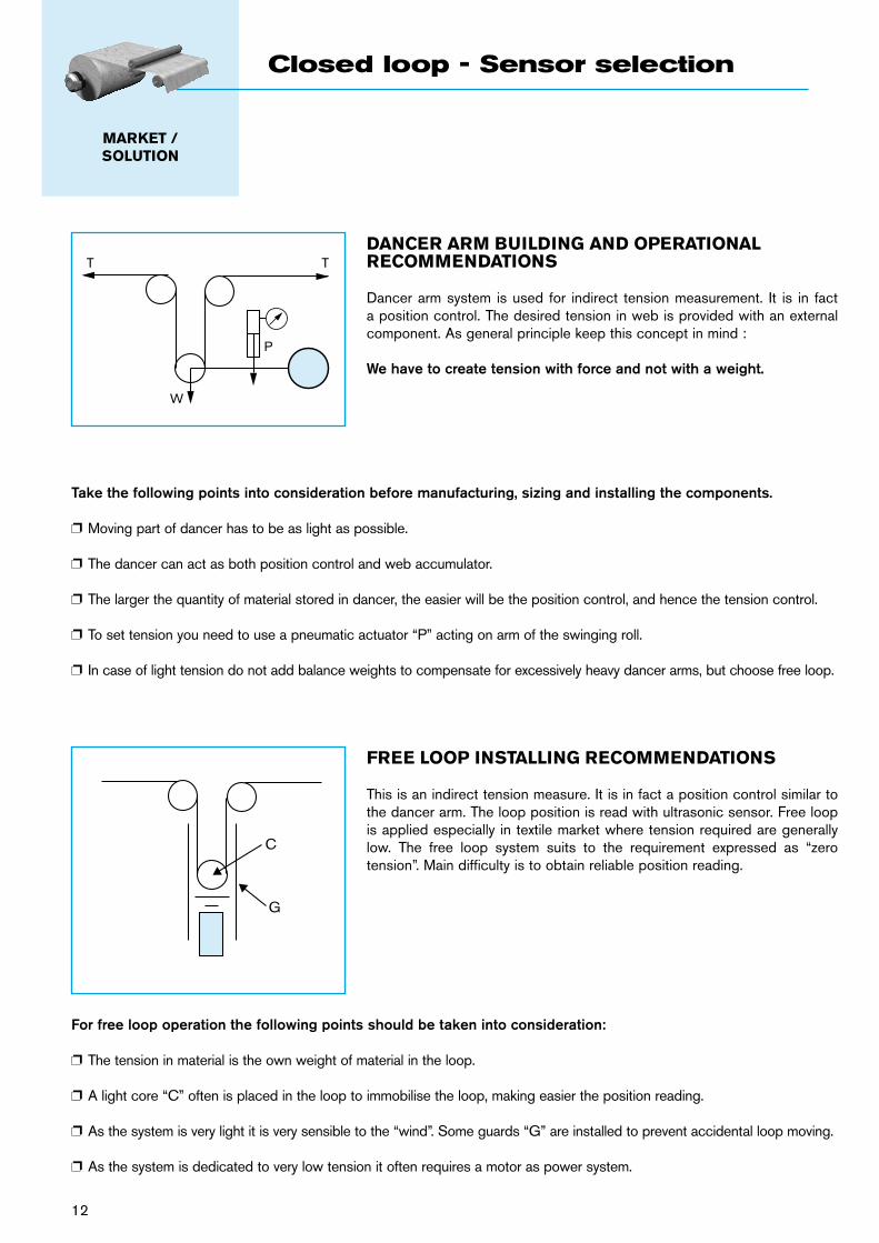
DANCER ARM BUILDING AND OPERATIONAL RECOMMENDATIONS
Dancer arm system is used for indirect tension measurement. It is in fact a position control. The desired tension in web is provided with an external component. As general principle keep this concept in mind :
We have to create tension with force and not with a weight.
Take the following points into consideration before manufacturing, sizing and installing the components.
p Moving part of dancer has to be as light as possible.
p The dancer can act as both position control and web accumulator.
p The larger the quantity of material stored in dancer, the easier will be the position control, and hence the tension control.
p To set tension you need to use a pneumatic actuator “P” acting on arm of the swinging roll.
p In case of light tension do not add balance weights to compensate for excessively heavy dancer arms, but choose free loop.
FREE LOOP INSTALLING RECOMMENDATIONS
This is an indirect tension measure. It is in fact a position control similar to the dancer arm. The loop position is read with ultrasonic sensor. Free loop is applied especially in textile market where tension required are generally low. The free loop system suits to the requirement expressed as “zero tension”. Main difficulty is to obtain reliable position reading.
For free loop operation the following points should be taken into consideration:
p The tension in material is the own weight of material in the loop.
p A light core “C” often is placed in the loop to immobilise the loop, making easier the position reading.
p As the system is very light it is very sensible to the “wind”. Some guards “G” are installed to prevent accidental loop moving.
p As the system is dedicated to very low tension it often requires a motor as power system.
T T
P
W
C
G
MARKET /SOLUTION
Closed loop - Sensor selection
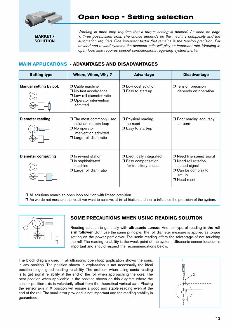
MAIN APPLICATIONS - ADVANTAGES AND DISADVANTAGES
Setting type Where, When, Why ? Advantage Disadvantage
Manual setting by pot. p Cable machine p Low cost solution p Tension precision p No fast accel/deccel p Easy to start-up depends on operation p Low roll diameter ratio p Operator intervention admitted
Diameter reading p The most commonly used p Physical reading, p Poor reading accuracy solution in open loop no reset on core p No operator p Easy to start-up intervention admitted p Large roll diam ratio
Diameter computing p In rewind station p Electrically integrated p Need line speed signal p In sophisticated p Easy compensation p Need roll rotation machine for transitory phases speed signal p Large roll diam ratio p Can be complex to set-up p Need reset
p All solutions remain an open loop solution with limited precision.p As we do not measure the result we want to achieve, all initial friction and inertia influence the precision of the system.
SOME PRECAUTIONS WHEN USING READING SOLUTION
Reading solution is generally with ultrasonic sensor. Another type of reading is the roll arm follower. Both use the same principle. The roll diameter measure is applied as torque setting on the power part driver. The sonic reading offers the advantage of not touching the roll. The reading reliability is the weak point of the system. Ultrasonic sensor location is important and should respect the recommendations below.
The block diagram used in all ultrasonic open loop application shows the sonic in any position. The position shown in explanation is not necessarily the ideal position to get good reading reliability. The problem when using sonic reading is to get signal reliability at the end of the roll when approaching the core. The best position when applicable is the position shown on this diagram where the sensor position axis is voluntarily offset from the theoretical vertical axis. Placing the sensor axis in X position will ensure a good and stable reading even at the end of the roll. The small error provided is not important and the reading stability is guaranteed.
X
Working in open loop requires that a torque setting is defined. As seen on page 7, three possibilities exist. The choice depends on the machine complexity and the automation required. One important factor that remains is the tension precision. For unwind and rewind systems the diameter ratio will play an important role. Working in open loop also requires special considerations regarding system inertia.
MARKET /SOLUTION
Open loop - Setting selection
13
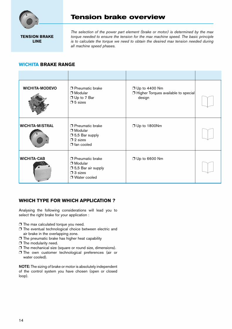
BRAKE TYPE MAIN CHARACTERISTICS TORQUE RANGE
WICHITA-MODEVO p Pneumatic brake p Up to 4400 Nm p Modular p Higher Torques available to special p Up to 7 Bar design p 5 sizes
WICHITA-MISTRAL p Pneumatic brake p Up to 1800Nm p Modular p 5,5 Bar supply p 2 sizes p fan cooled
WICHITA-CAB p Pneumatic brake p Up to 6600 Nm p Modular p 5,5 Bar air supply p 3 sizes p Water cooled
14
WICHITA BRAKE RANGE
The selection of the power part element (brake or motor) is determined by the max torque needed to ensure the tension for the max machine speed. The basic principle is to calculate the torque we need to obtain the desired max tension needed during all machine speed phases.
TENSION BRAKE LINE
Tension brake overview
WHICH TYPE FOR WHICH APPLICATION ?
Analysing the following considerations will lead you to select the right brake for your application :
p The max calculated torque you need.p The eventual technological choice between electric and
air brake in the overlapping zone.p The pneumatic brake has higher heat capabilityp The modularity need.p The mechanical size (square or round size, dimensions).p The own customer technological preferences (air or
water cooled).
NOTE: The sizing of brake or motor is absolutely independent of the control system you have chosen (open or closed loop).
16 19
20
21 23
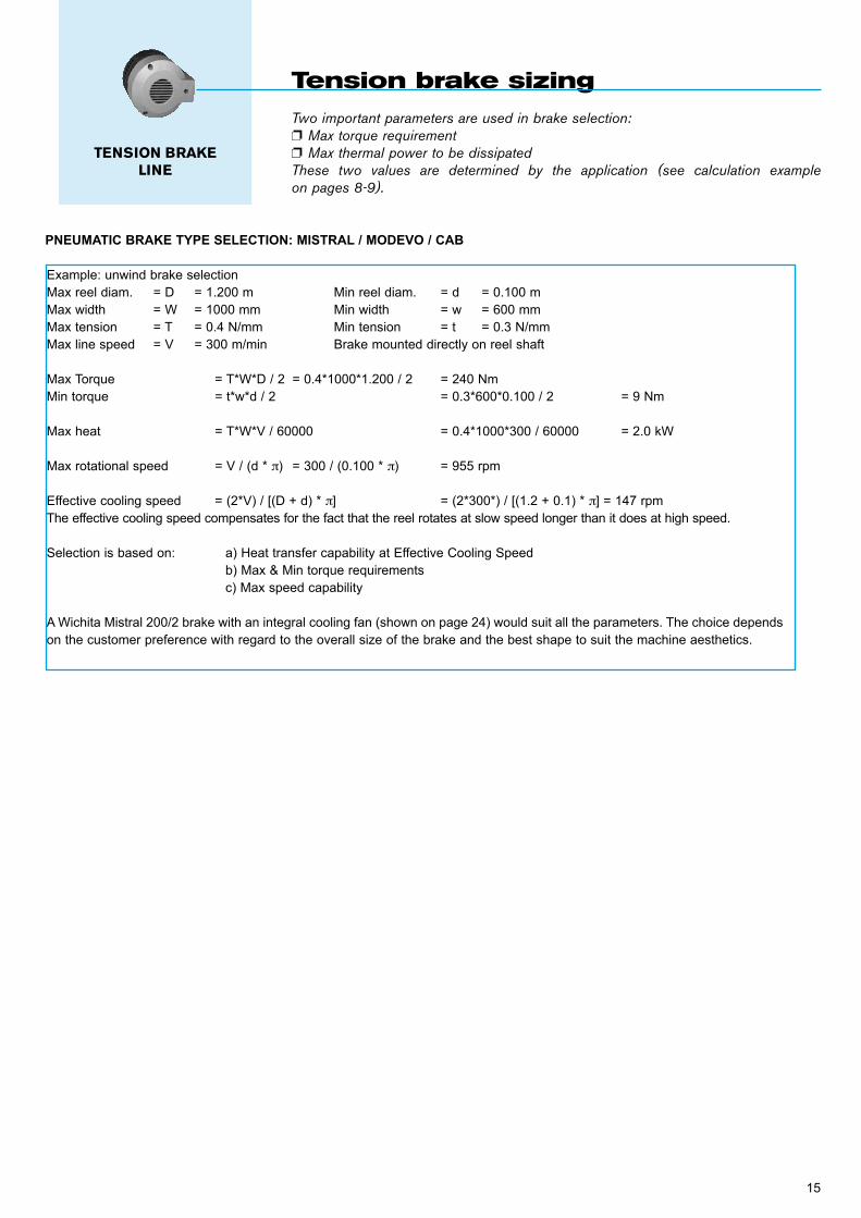
Two important parameters are used in brake selection:p Max torque requirementp Max thermal power to be dissipatedThese two values are determined by the application (see calculation example on pages 8-9).
Tension brake sizing
PNEUMATIC BRAKE TYPE SELECTION: MISTRAL / MODEVO / CAB
Example: unwind brake selectionMax reel diam. = D = 1.200 m Min reel diam. = d = 0.100 mMax width = W = 1000 mm Min width = w = 600 mmMax tension = T = 0.4 N/mm Min tension = t = 0.3 N/mmMax line speed = V = 300 m/min Brake mounted directly on reel shaft
Max Torque = T*W*D / 2 = 0.4*1000*1.200 / 2 = 240 NmMin torque = t*w*d / 2 = 0.3*600*0.100 / 2 = 9 Nm
Max heat = T*W*V / 60000 = 0.4*1000*300 / 60000 = 2.0 kW
Max rotational speed = V / (d * π) = 300 / (0.100 * π) = 955 rpm
Effective cooling speed = (2*V) / [(D + d) * π] = (2*300*) / [(1.2 + 0.1) * π] = 147 rpmThe effective cooling speed compensates for the fact that the reel rotates at slow speed longer than it does at high speed.
Selection is based on: a) Heat transfer capability at Effective Cooling Speed b) Max & Min torque requirements c) Max speed capability
A Wichita Mistral 200/2 brake with an integral cooling fan (shown on page 24) would suit all the parameters. The choice depends on the customer preference with regard to the overall size of the brake and the best shape to suit the machine aesthetics.
15
TENSION BRAKE LINE
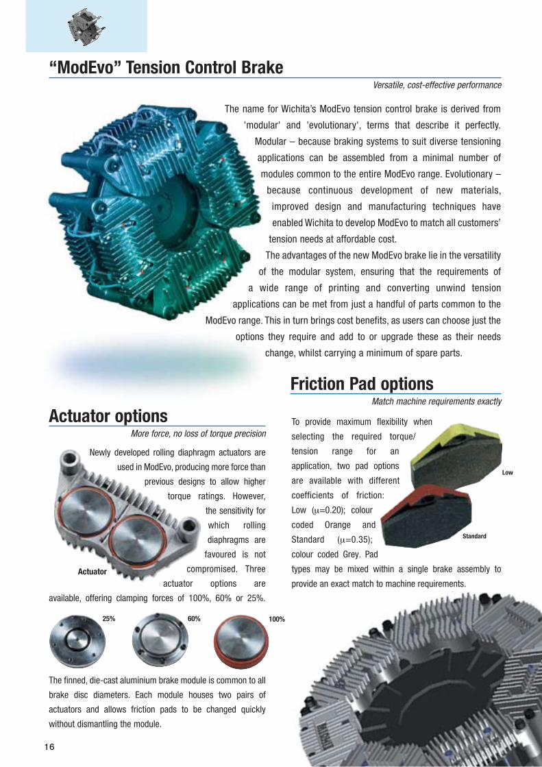
The name for Wichita’s ModEvo tension control brake is derived from
'modular' and 'evolutionary', terms that describe it perfectly.
Modular – because braking systems to suit diverse tensioning
applications can be assembled from a minimal number of
modules common to the entire ModEvo range. Evolutionary –
because continuous development of new materials,
improved design and manufacturing techniques have
enabled Wichita to develop ModEvo to match all customers’
tension needs at affordable cost.
The advantages of the new ModEvo brake lie in the versatility
of the modular system, ensuring that the requirements of
a wide range of printing and converting unwind tension
applications can be met from just a handful of parts common to the
ModEvo range. This in turn brings cost benefits, as users can choose just the
options they require and add to or upgrade these as their needs
change, whilst carrying a minimum of spare parts.
“ModEvo” Tension Control BrakeVersatile, cost-effective performance
Newly developed rolling diaphragm actuators are
used in ModEvo, producing more force than
previous designs to allow higher
torque ratings. However,
the sensitivity for
which rolling
diaphragms are
favoured is not
compromised. Three
actuator options are
available, offering clamping forces of 100%, 60% or 25%.
The finned, die-cast aluminium brake module is common to all
brake disc diameters. Each module houses two pairs of
actuators and allows friction pads to be changed quickly
without dismantling the module.
To provide maximum flexibility when
selecting the required torque/
tension range for an
application, two pad options
are available with different
coefficients of friction:
Low (µ=0.20); colour
coded Orange and
Standard (µ=0.35);
colour coded Grey. Pad
types may be mixed within a single brake assembly to
provide an exact match to machine requirements.
100%60%25%
Actuator
Actuator optionsMore force, no loss of torque precision
Friction Pad optionsMatch machine requirements exactly
Low
Standard
16
The name for Wichita’s ModEvo tension control brake is derived from
'modular' and 'evolutionary', terms that describe it perfectly.
Modular – because braking systems to suit diverse tensioning
applications can be assembled from a minimal number of
modules common to the entire ModEvo range. Evolutionary –
because continuous development of new materials,
improved design and manufacturing techniques have
enabled Wichita to develop ModEvo to match all customers’
tension needs at affordable cost.
The advantages of the new ModEvo brake lie in the versatility
of the modular system, ensuring that the requirements of
a wide range of printing and converting unwind tension
applications can be met from just a handful of parts common to the
ModEvo range. This in turn brings cost benefits, as users can choose just the
options they require and add to or upgrade these as their needs
change, whilst carrying a minimum of spare parts.
“ModEvo” Tension Control BrakeVersatile, cost-effective performance
Newly developed rolling diaphragm actuators are
used in ModEvo, producing more force than
previous designs to allow higher
torque ratings. However,
the sensitivity for
which rolling
diaphragms are
favoured is not
compromised. Three
actuator options are
available, offering clamping forces of 100%, 60% or 25%.
The finned, die-cast aluminium brake module is common to all
brake disc diameters. Each module houses two pairs of
actuators and allows friction pads to be changed quickly
without dismantling the module.
To provide maximum flexibility when
selecting the required torque/
tension range for an
application, two pad options
are available with different
coefficients of friction:
Low (µ=0.20); colour
coded Orange and
Standard (µ=0.35);
colour coded Grey. Pad
types may be mixed within a single brake assembly to
provide an exact match to machine requirements.
100%60%25%
Actuator
Actuator optionsMore force, no loss of torque precision
Friction Pad optionsMatch machine requirements exactly
Low
Standard
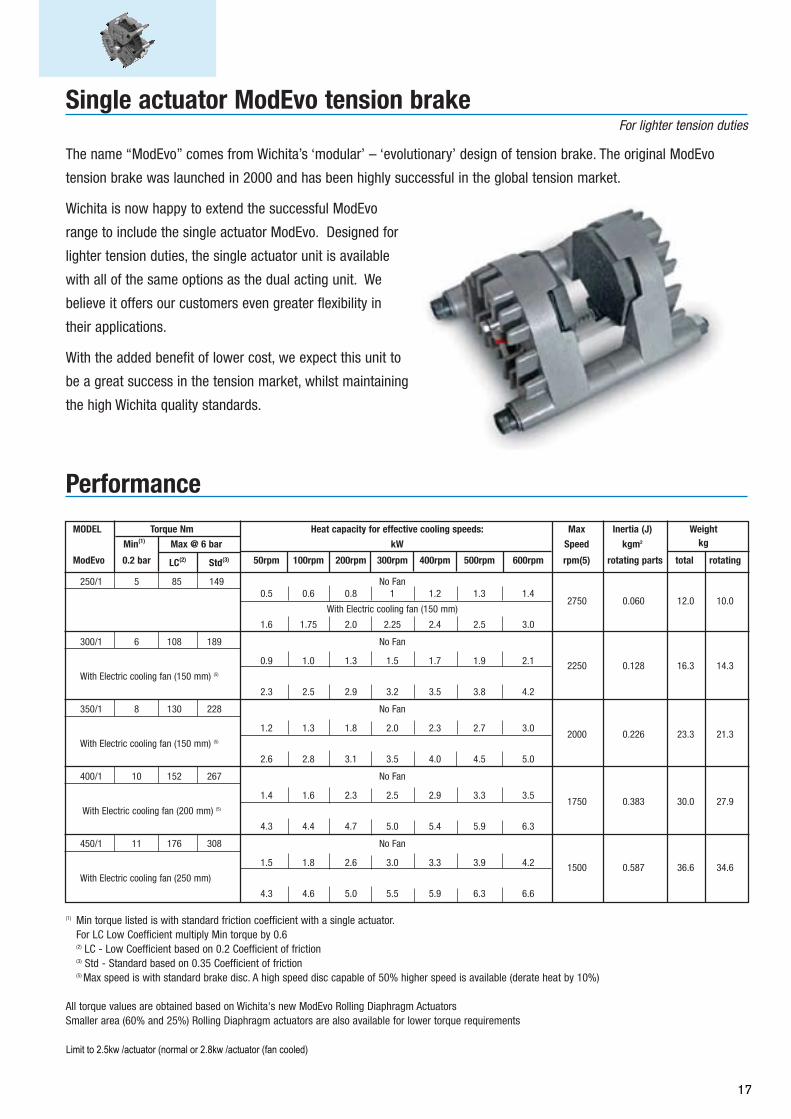
The name “ModEvo” comes from Wichita’s ‘modular’ – ‘evolutionary’ design of tension brake. The original ModEvo
tension brake was launched in 2000 and has been highly successful in the global tension market.
Wichita is now happy to extend the successful ModEvo
range to include the single actuator ModEvo. Designed for
lighter tension duties, the single actuator unit is available
with all of the same options as the dual acting unit. We
believe it offers our customers even greater flexibility in
their applications.
With the added benefit of lower cost, we expect this unit to
be a great success in the tension market, whilst maintaining
the high Wichita quality standards.
MODEL Torque Nm Heat capacity for effective cooling speeds: Max Inertia (J) Weight
Min(1) Max @ 6 bar kW Speed kgm2 kg
ModEvo 0.2 bar LC(2) Std(3) 50rpm 100rpm 200rpm 300rpm 400rpm 500rpm 600rpm rpm(5) rotating parts total rotating
250/1 5 85 149 No Fan0.5 0.6 0.8 1 1.2 1.3 1.4
2750 0.060 12.0 10.0With Electric cooling fan (150 mm)
1.6 1.75 2.0 2.25 2.4 2.5 3.0
300/1 6 108 189 No Fan
0.9 1.0 1.3 1.5 1.7 1.9 2.1 2250 0.128 16.3 14.3With Electric cooling fan (150 mm) (5)
2.3 2.5 2.9 3.2 3.5 3.8 4.2
350/1 8 130 228 No Fan
1.2 1.3 1.8 2.0 2.3 2.7 3.02000 0.226 23.3 21.3
With Electric cooling fan (150 mm) (5)
2.6 2.8 3.1 3.5 4.0 4.5 5.0
400/1 10 152 267 No Fan
1.4 1.6 2.3 2.5 2.9 3.3 3.51750 0.383 30.0 27.9
With Electric cooling fan (200 mm) (5)
4.3 4.4 4.7 5.0 5.4 5.9 6.3
450/1 11 176 308 No Fan
1.5 1.8 2.6 3.0 3.3 3.9 4.2 1500 0.587 36.6 34.6With Electric cooling fan (250 mm)
4.3 4.6 5.0 5.5 5.9 6.3 6.6
(1) Min torque listed is with standard friction coefficient with a single actuator.For LC Low Coefficient multiply Min torque by 0.6(2) LC - Low Coefficient based on 0.2 Coefficient of friction(3) Std - Standard based on 0.35 Coefficient of friction(5) Max speed is with standard brake disc. A high speed disc capable of 50% higher speed is available (derate heat by 10%)
All torque values are obtained based on Wichita's new ModEvo Rolling Diaphragm ActuatorsSmaller area (60% and 25%) Rolling Diaphragm actuators are also available for lower torque requirements
Limit to 1.25 kw/ actuator (normal) or 1.5 kw/ actuator (fan cooled)Limit Lo-Co to 70% of above heat ratings
Performance
Single actuator ModEvo tension brakeFor lighter tension duties
17
Limit to 2.5kw /actuator (normal or 2.8kw /actuator (fan cooled)
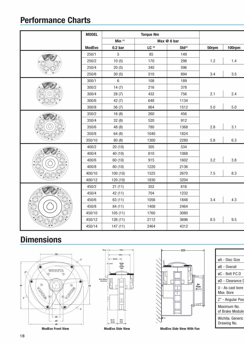
ModEvo Dimensions Table
øA - Disc Size 250 300 350 400 450
øB - Overall 324 369 415 461 508
øC - Bolt P.C.D 298.5 343.5 389 435.5 482.5
øD - Clearance Dia. 90 140 190 240 290
U - As cast bore SOLID SOLID 25 25 25Max. Bore 55 79 117 136 154
Z” - Angular Position 120˚ 90˚ 72˚ 60˚ 51.4˚
Maximum No. 3 4 5 6 7of Brake Modules
Wichita. Generic 73125-000 73130-000 73135-000 73141-000 73145-000Drawing No.
MODEL Torque Nm Heat capacity for effective cooling speeds: Max Inertia (J) Weight
Min (1) Max @ 6 bar kW Speed kgm2 kg
ModEvo 0.2 bar LC (2) Std(3) 50rpm 100rpm 200rpm 300rpm 400rpm 500 rpm 600 rpm rpm (4) rotating parts total rotating
250/1 5 85 149 No Fan 12.4
250/2 10 (5) 170 298 1.2 1.4 1.9 2.4 2.7 3.0 3.22250 0.060
13.2
250/4 20 (5) 340 596 With Electric cooling fan 17.6 8.7
250/6 30 (5) 510 894 3.4 3.5 3.8 4.0 4.0 4.0 4.0 22.1
300/1 6 108 189 17.3
300/2 14 (7) 216 378 No Fan 18.1
300/4 28 (7) 432 756 2.1 2.4 3.0 3.5 4.0 4.5 5.01900 0.125
22.5 13.6
300/6 42 (7) 648 1134 With Electric cooling fan 27.0
300/8 56 (7) 864 1512 5.0 5.0 5.0 5.0 5.5 6.0 6.0 31.5
350/2 16 (8) 260 456 24.8
350/4 32 (8) 520 912 No Fan 29.2
350/6 48 (8) 780 1368 2.8 3.1 4.2 4.8 5.5 6.6 7.21650 0.23
33.7 20.3
350/8 64 (8) 1040 1824 With Electric cooling fan 38.2
350/10 80 (8) 1300 2280 5.8 6.3 6.5 6.5 6.5 6.5 6.5 42.7
400/2 20 (10) 305 534 31.3
400/4 40 (10) 610 1068 No Fan 35.7
400/6 60 (10) 915 1602 3.2 3.8 5.4 6.0 6.8 7.8 8.41450 0.4
40.2 26.8
400/8 80 (10) 1220 2136 With Electric cooling fan 44.7
400/10 100 (10) 1525 2670 7.5 8.3 8.7 9.3 10.0 10.0 10.0 49.2
400/12 120 (10) 1830 3204 53.6
450/2 21 (11) 352 616 37.5
450/4 42 (11) 704 1232 No Fan 41.9
450/6 63 (11) 1056 1848 3.4 4.3 6.1 7.0 7.8 9.2 10.0 46.4
450/8 84 (11) 1408 2464 50.9 33
450/10 105 (11) 1760 3080 With Electric cooling fan 55.4
450/12 126 (11) 2112 3696 8.5 9.5 10.0 10.8 11.6 12.5 13.3 59.8
450/14 147 (11) 2464 4312 64.3
Performance Charts
139.5
159.5
85.25
11
18
44.043.6
63.1563.55
M12x160mmCap Screw
BrakeDisc
CentreLine
Dimensions
184
øAøC
Z˚
Z˚
Z˚
25
øU
øD
øB
223
AirFlow
ModEvo Front View ModEvo Side View ModEvo Side View With Fan
ModEvo
(1) Min torque listed is with standard friction coefficient. Values
in (brackets) are with a single actuator.
For LC Low Coefficient multiply Min torque by 0.6.(2) LC - Low Coefficient based on 0.2 Coefficient of friction(3) Std - Standard based on 0.35 Coefficient of friction(4) Max speed is with standard brake disc. A high speed brake
disc capable of 50% higher speed is also available.
All torque values are obtained based on Wichita’s new ModEvo
Rolling Diaphragm Actuators. Smaller area (60% and 25%)
Rolling Diaphragm actuators are also available for lower torque
requirements.
1250 0.61
18
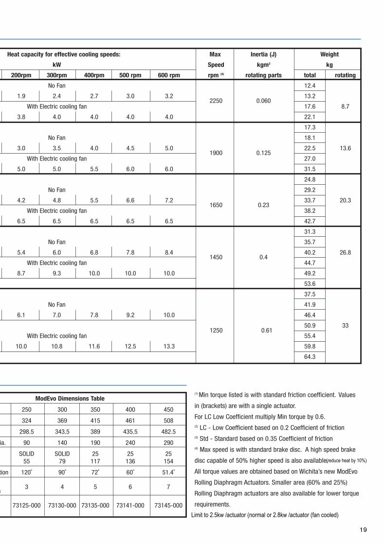
ModEvo Dimensions Table
øA - Disc Size 250 300 350 400 450
øB - Overall 324 369 415 461 508
øC - Bolt P.C.D 298.5 343.5 389 435.5 482.5
øD - Clearance Dia. 90 140 190 240 290
U - As cast bore SOLID SOLID 25 25 25Max. Bore 55 79 117 136 154
Z” - Angular Position 120˚ 90˚ 72˚ 60˚ 51.4˚
Maximum No. 3 4 5 6 7of Brake Modules
Wichita. Generic 73125-000 73130-000 73135-000 73141-000 73145-000Drawing No.
MODEL Torque Nm Heat capacity for effective cooling speeds: Max Inertia (J) Weight
Min (1) Max @ 6 bar kW Speed kgm2 kg
ModEvo 0.2 bar LC (2) Std(3) 50rpm 100rpm 200rpm 300rpm 400rpm 500 rpm 600 rpm rpm (4) rotating parts total rotating
250/1 5 85 149 No Fan 12.4
250/2 10 (5) 170 298 1.2 1.4 1.9 2.4 2.7 3.0 3.22250 0.060
13.2
250/4 20 (5) 340 596 With Electric cooling fan 17.6 8.7
250/6 30 (5) 510 894 3.4 3.5 3.8 4.0 4.0 4.0 4.0 22.1
300/1 6 108 189 17.3
300/2 14 (7) 216 378 No Fan 18.1
300/4 28 (7) 432 756 2.1 2.4 3.0 3.5 4.0 4.5 5.01900 0.125
22.5 13.6
300/6 42 (7) 648 1134 With Electric cooling fan 27.0
300/8 56 (7) 864 1512 5.0 5.0 5.0 5.0 5.5 6.0 6.0 31.5
350/2 16 (8) 260 456 24.8
350/4 32 (8) 520 912 No Fan 29.2
350/6 48 (8) 780 1368 2.8 3.1 4.2 4.8 5.5 6.6 7.21650 0.23
33.7 20.3
350/8 64 (8) 1040 1824 With Electric cooling fan 38.2
350/10 80 (8) 1300 2280 5.8 6.3 6.5 6.5 6.5 6.5 6.5 42.7
400/2 20 (10) 305 534 31.3
400/4 40 (10) 610 1068 No Fan 35.7
400/6 60 (10) 915 1602 3.2 3.8 5.4 6.0 6.8 7.8 8.41450 0.4
40.2 26.8
400/8 80 (10) 1220 2136 With Electric cooling fan 44.7
400/10 100 (10) 1525 2670 7.5 8.3 8.7 9.3 10.0 10.0 10.0 49.2
400/12 120 (10) 1830 3204 53.6
450/2 21 (11) 352 616 37.5
450/4 42 (11) 704 1232 No Fan 41.9
450/6 63 (11) 1056 1848 3.4 4.3 6.1 7.0 7.8 9.2 10.0 46.4
450/8 84 (11) 1408 2464 50.9 33
450/10 105 (11) 1760 3080 With Electric cooling fan 55.4
450/12 126 (11) 2112 3696 8.5 9.5 10.0 10.8 11.6 12.5 13.3 59.8
450/14 147 (11) 2464 4312 64.3
Performance Charts
139.5
159.5
85.25
11
18
44.043.6
63.1563.55
M12x160mmCap Screw
BrakeDisc
CentreLine
Dimensions
184
øAøC
Z˚
Z˚
Z˚
25
øU
øD
øB
223
AirFlow
ModEvo Front View ModEvo Side View ModEvo Side View With Fan
ModEvo
(1) Min torque listed is with standard friction coefficient. Values
in (brackets) are with a single actuator.
For LC Low Coefficient multiply Min torque by 0.6.(2) LC - Low Coefficient based on 0.2 Coefficient of friction(3) Std - Standard based on 0.35 Coefficient of friction(4) Max speed is with standard brake disc. A high speed brake
disc capable of 50% higher speed is also available.
All torque values are obtained based on Wichita’s new ModEvo
Rolling Diaphragm Actuators. Smaller area (60% and 25%)
Rolling Diaphragm actuators are also available for lower torque
requirements.
1250 0.61
19
Limit to 2.5kw /actuator (normal or 2.8kw /actuator (fan cooled)
(reduce heat by 10%)
20
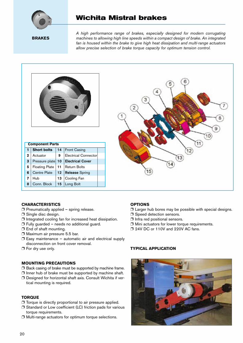
CHARACTERISTICSp Pneumatically applied – spring release.p Single disc design. p Integrated cooling fan for increased heat dissipation.p Fully guarded – needs no additional guard.p End of shaft mounting.p Maximum air pressure 5.5 bar. p Easy maintenance – automatic air and electrical supply
disconnection on front cover removal. p For dry use only.
MOUNTING PRECAUTIONSp Back casing of brake must be supported by machine frame.p Inner hub of brake must be supported by machine shaft.p Designed for horizontal shaft axis. Consult Wichita if ver-
tical mounting is required.
TORQUEp Torque is directly proportional to air pressure applied.p Standard or Low coefficient (LC) friction pads for various
torque requirements.p Multi-range actuators for optimum torque selections.
OPTIONS p Larger hub bores may be possible with special designs.p Speed detection sensors.p Infra red positional sensors. p Mini actuators for lower torque requirements.p 24V DC or 110V and 220V AC fans.
TYPICAL APPLICATION
A high performance range of brakes, especially designed for modern corrugating machines to allowing high line speeds within a compact design of brake. An integrated fan is housed within the brake to give high heat dissipation and multi-range actuators allow precise selection of brake torque capacity for optimum tension control.
Wichita Mistral brakes
BRAKES
Component Parts
1 Short bolts 14 Front Casing
2 Actuator 9 Electrical Connector
3 Pressure plate 10 Electrical Cover
5 Floating Plate 11 Return Bolts
6 Centre Plate 12 Release Spring
7 Hub 13 Cooling Fan
8 Conn. Block 15 Long Bolt
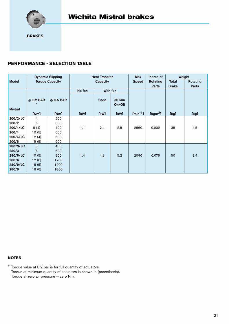
PERFORMANCE - SELECTION TABLE
NOTES
* Torque value at 0.2 bar is for full quantity of actuators. Torque at minimum quantity of actuators is shown in (parenthesis). Torque at zero air pressure = zero Nm.
Dynamic Slipping Heat Transfer Max Inertia of WeightModel Torque Capacity Capacity Speed Rotating Total Rotating Parts Brake Parts No fan With fan
@ 0.2 BAR @ 5.5 BAR Cont 30 Min * On/OffMistral [Nm] [Nm] [kW] [kW] [kW] [min-1] [kgm2] [kg] [kg]200/2/LC 4 200 200/2 5 300 200/4/LC 8 (4) 400 1,1 2,4 2,8 2860 0,032 35 4,5200/4 10 (5) 600 200/6/LC 12 (4) 600 200/6 15 (5) 900 280/3/LC 5 400 280/3 6 600 280/6/LC 10 (5) 800 1,4 4,8 5,2 2090 0,076 50 9,4280/6 12 (6) 1200 280/9/LC 15 (5) 1200 280/9 18 (6) 1800
21
Wichita Mistral brakes
BRAKES
22
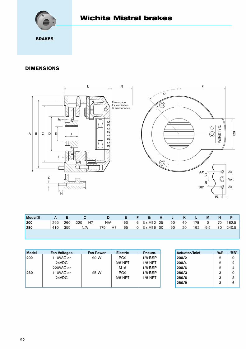
DIMENSIONS
K°
L N P
120
M
F
J
H
G
EDCBA
3030
15
Free spacefor ventilation& maintenance
‘AA’
‘BB’
Air
Volt
Air
Wichita Mistral brakes
BRAKES
Model(l) A B C D E F G H J K L M N P200 295 260 220 H7 N/A 60 6 3 x M12 25 50 40 178 0 70 182.5280 410 355 N/A 175 H7 65 0 3 x M16 30 60 20 192 9.5 80 240.5
Actuator/Inlet ‘AA’ ‘BB’200/2 2 0200/4 2 2200/6 2 4280/3 3 0280/6 3 3280/9 3 6
Model Fan Voltages Fan Power Electric Pneum.200 110VAC or 20 W PG9 1/8 BSP 24VDC 3/8 NPT 1/8 NPT 220VAC or M16 1/8 BSP280 110VAC or 25 W PG9 1/8 BSP 24VDC 3/8 NPT 1/8 NPT
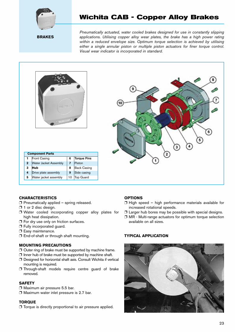
Pneumatically actuated, water cooled brakes designed for use in constantly slipping applications. Utilising copper alloy wear plates, the brake has a high power rating within a reduced envelope size. Optimum torque selection is achieved by utilising either a single annular piston or multiple piston actuators for finer torque control. Visual wear indicator is incorporated in standard.
BRAKES
Wichita CAB - Copper Alloy Brakes
CHARACTERISTICSp Pneumatically applied – spring released.p 1 or 2 disc design.p Water cooled incorporating copper alloy plates for
high heat dissipation.p For dry use only on friction surfaces.p Fully incorporated guard. p Easy maintenance.p End-of-shaft or through shaft mounting.
MOUNTING PRECAUTIONSp Outer ring of brake must be supported by machine frame.p Inner hub of brake must be supported by machine shaft.p Designed for horizontal shaft axis. Consult Wichita if vertical
mounting is required.p Through-shaft models require centre guard of brake
removed.
SAFETYp Maximum air pressure 5.5 bar. p Maximum water inlet pressure is 2.7 bar.
TORQUEp Torque is directly proportional to air pressure applied.
OPTIONS p High speed – high performance materials available for
increased rotational speeds.p Larger hub bores may be possible with special designs.p MR - Multi-range actuators for optimum torque selection
available on all sizes.
TYPICAL APPLICATION
Component Parts
1 Front Casing 6 Torque Pins 2 Water Jacket Assembly 7 Piston
3 Hub 8 Back Casing
4 Drive plate assembly 9 Side casing
5 Water jacket assembly 10 Top Guard
23
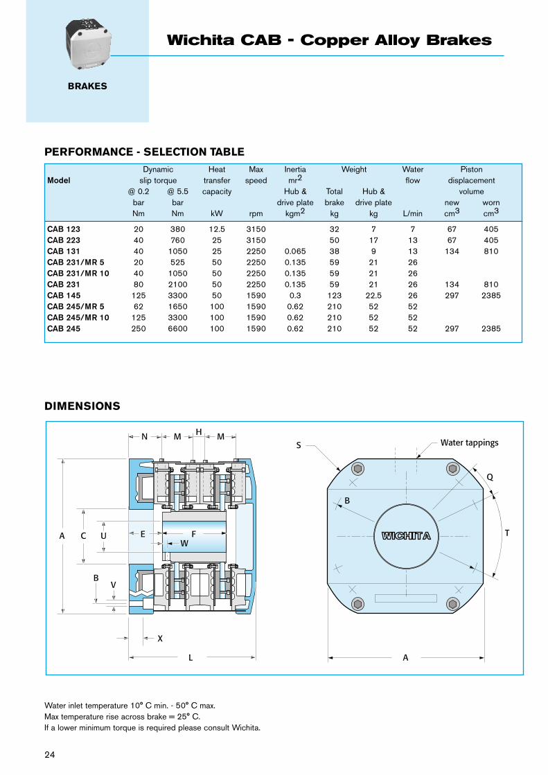
Water inlet temperature 10° C min. - 50° C max. Max temperature rise across brake = 25° C. If a lower minimum torque is required please consult Wichita.
N
A C U E FW
VB
X
L A
S
B
Q
T
M MHWater tappings
DIMENSIONS
24
BRAKES
Wichita CAB - Copper Alloy Brakes
PERFORMANCE - SELECTION TABLE
Dynamic Heat Max Inertia Weight Water PistonModel slip torque transfer speed mr2 flow displacement @ 0.2 @ 5.5 capacity Hub & Total Hub & volume bar bar drive plate brake drive plate new worn Nm Nm kW rpm kgm2 kg kg L/min cm3 cm3
CAB 123 20 380 12.5 3150 32 7 7 67 405CAB 223 40 760 25 3150 50 17 13 67 405CAB 131 40 1050 25 2250 0.065 38 9 13 134 810CAB 231/MR 5 20 525 50 2250 0.135 59 21 26 CAB 231/MR 10 40 1050 50 2250 0.135 59 21 26 CAB 231 80 2100 50 2250 0.135 59 21 26 134 810CAB 145 125 3300 50 1590 0.3 123 22.5 26 297 2385CAB 245/MR 5 62 1650 100 1590 0.62 210 52 52 CAB 245/MR 10 125 3300 100 1590 0.62 210 52 52 CAB 245 250 6600 100 1590 0.62 210 52 52 297 2385
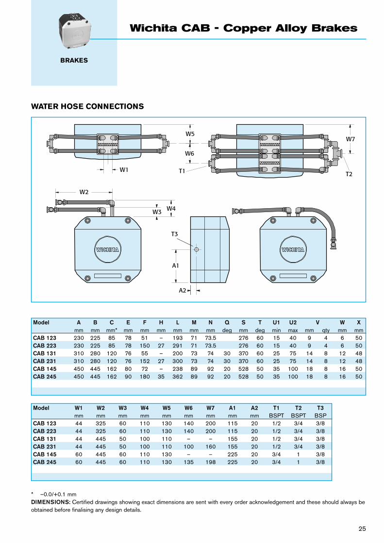
* –0.0/+0.1 mmDIMENSIONS: Certified drawings showing exact dimensions are sent with every order acknowledgement and these should always be obtained before finalising any design details.
W4W3
W2
W1 T1
W5
T2
W7
W6
A1
T3
A2
Model W1 W2 W3 W4 W5 W6 W7 A1 A2 T1 T2 T3 mm mm mm mm mm mm mm mm mm BSPT BSPT BSPCAB 123 44 325 60 110 130 140 200 115 20 1/2 3/4 3/8CAB 223 44 325 60 110 130 140 200 115 20 1/2 3/4 3/8CAB 131 44 445 50 100 110 – – 155 20 1/2 3/4 3/8CAB 231 44 445 50 100 110 100 160 155 20 1/2 3/4 3/8CAB 145 60 445 60 110 130 – – 225 20 3/4 1 3/8CAB 245 60 445 60 110 130 135 198 225 20 3/4 1 3/8
Model A B C E F H L M N Q S T U1 U2 V W X mm mm mm* mm mm mm mm mm mm deg mm deg min max mm qty mm mmCAB 123 230 225 85 78 51 – 193 71 73.5 276 60 15 40 9 4 6 50CAB 223 230 225 85 78 150 27 291 71 73.5 276 60 15 40 9 4 6 50CAB 131 310 280 120 76 55 – 200 73 74 30 370 60 25 75 14 8 12 48CAB 231 310 280 120 76 152 27 300 73 74 30 370 60 25 75 14 8 12 48CAB 145 450 445 162 80 72 – 238 89 92 20 528 50 35 100 18 8 16 50CAB 245 450 445 162 90 180 35 362 89 92 20 528 50 35 100 18 8 16 50
WATER HOSE CONNECTIONS
25
BRAKES
Wichita CAB - Copper Alloy Brakes
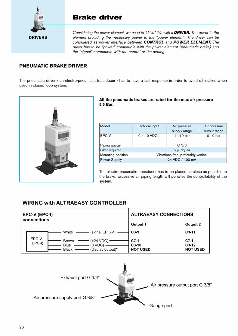
PNEUMATIC BRAKE DRIVER
All the pneumatic brakes are rated for the max air pressure 5,5 Bar.
The pneumatic driver - an electro-pneumatic transducer - has to have a fast response in order to avoid difficulties when used in closed loop system.
Model Electrical input Air pressure Air pressure supply range output rangeEPC-V 0 – 10 VDC 1 - 10 bar 0 - 9 bar
Piping gauge G 3/8 Filter required 5 µ, dry air Mounting position Vibrations free, preferably vertical Power Supply 24 VDC / 100 mA
26
The electro-pneumatic transducer has to be placed as close as possible to the brake. Excessive air piping length will penalise the controllability of the system.
Considering the power element, we need to “drive” this with a DRIVER. The driver is the element providing the necessary power to the “power element”. The driver can be considered as power interface between CONTROL and POWER ELEMENT. The driver has to be “power” compatible with the power element (pneumatic brake) and the “signal” compatible with the control or the setting.
DRIVERS
Brake driver
1 of 1
WIRING with ALTRAEASY CONTROLLER
EPC-V (EPC-I) ALTRAEASY CONNECTIONS connections Output 1 Output 2
White (signal EPC-V) C3-9 C3-11 Brown (+24 VDC) C7-1 C7-1 Blue (0 VDC) C3-10 C3-12 Black (display output)* NOT USED NOT USED
EPC-V(EPC-I)
Exhaust port G 1/4”
Air pressure supply port G 3/8”
Gauge port
Air pressure output port G 3/8”
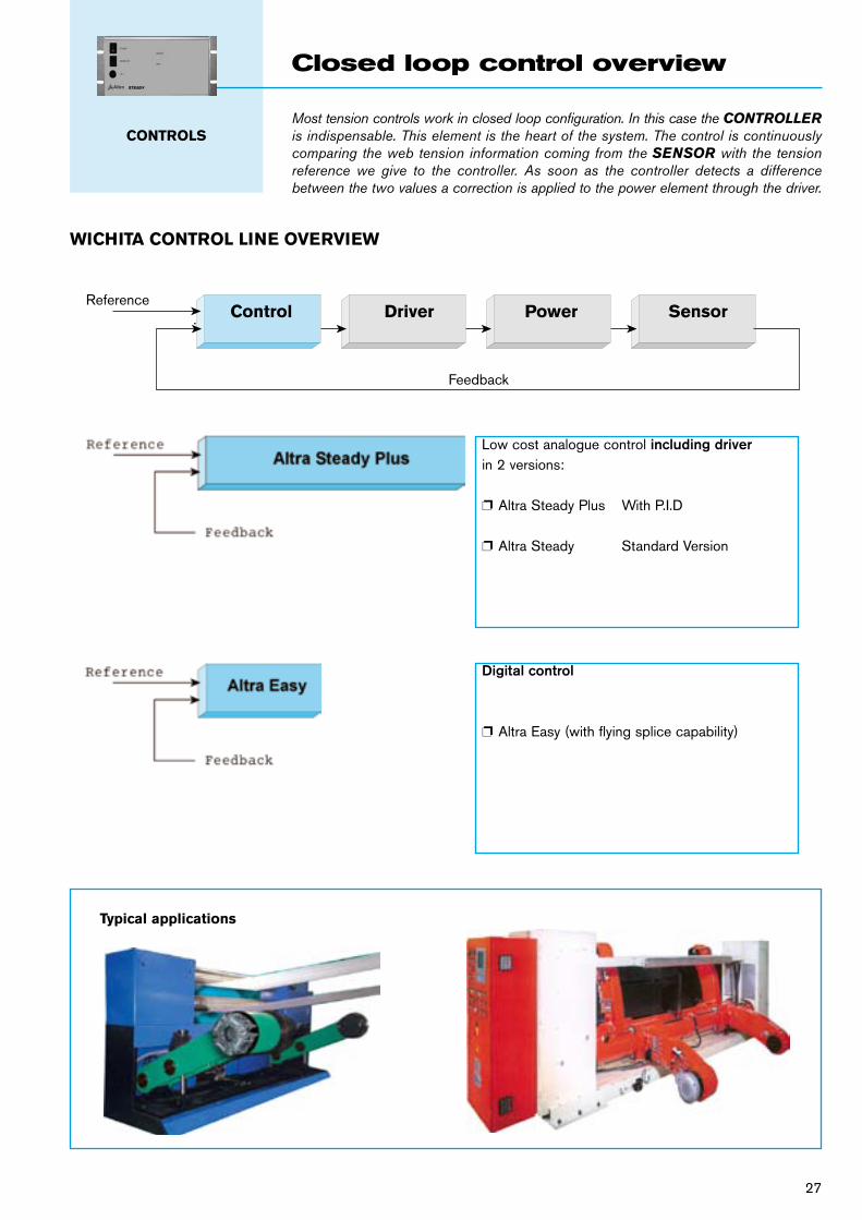
Most tension controls work in closed loop configuration. In this case the CONTROLLER is indispensable. This element is the heart of the system. The control is continuously comparing the web tension information coming from the SENSOR with the tension reference we give to the controller. As soon as the controller detects a difference between the two values a correction is applied to the power element through the driver.
CONTROLS
Closed loop control overview
WICHITA CONTROL LINE OVERVIEW
Low cost analogue control including driverin 2 versions:
p Altra Steady Plus With P.I.D
p Altra Steady Standard Version
Digital control
p Altra Easy (with flying splice capability)
Control Driver Power SensorReference
Feedback
Typical applications
27
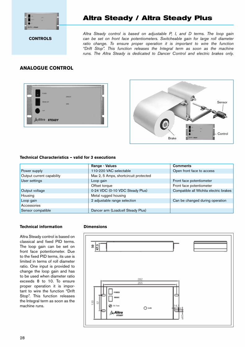
Altra Steady control is based on adjustable P, I, and D terms. The loop gain can be set on front face potentiometers. Switcheable gain for large roll diameter ratio change. To ensure proper operation it is important to wire the function “Drift Stop”. This function releases the Integral term as soon as the machine runs. The Altra Steady is dedicated to Dancer Control and electric brakes only.
CONTROLS
Altra Steady / Altra Steady Plus
ANALOGUE CONTROL
BrakeControl
Sensor
28
Dimensions
Range - Values CommentsPower supply 110-220 VAC selectable Open front face to accessOutput current capability Max 2, 5 Amps, shortcircuit protected User settings Loop gain Front face potentiometer Offset torque Front face potentiometerOutput voltage 0-24 VDC (0-10 VDC Steady Plus) Compatible all Wichita electric brakesHousing Metal rugged housing Loop gain 2 adjustable range selection Can be changed during operationAccessories Sensor compatible Dancer arm (Loadcell Steady Plus)
Technical Characteristics – valid for 3 executions
Technical information
Altra Steady control is based on classical and fixed PID terms. The loop gain can be set on front face potentiometer. Due to the fixed PID terms, its use is limited in terms of roll diameter ratio. One input is provided to change the loop gain and has to be used when diameter ratio exceeds 8 to 10. To ensure proper operation it is impor-tant to wire the function “Drift Stop”. This function releases the Integral term as soon as the machine runs.
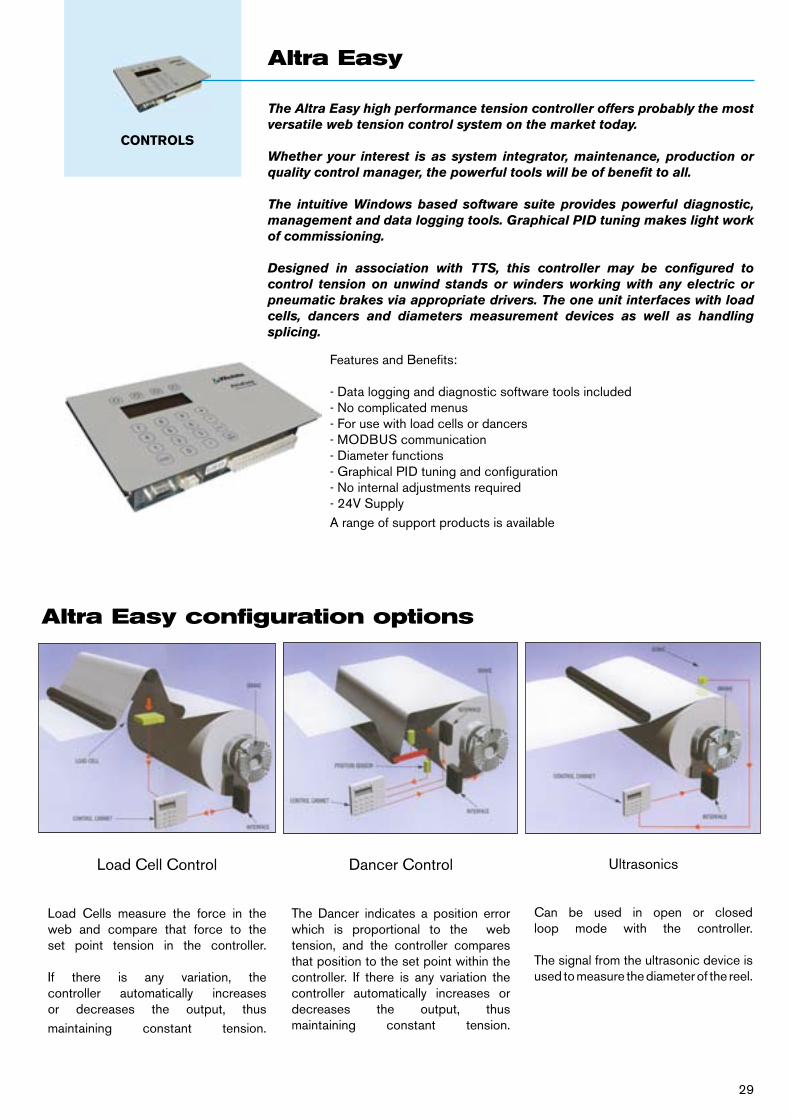
The Altra Easy high performance tension controller offers probably the most versatile web tension control system on the market today.
Whether your interest is as system integrator, maintenance, production or quality control manager, the powerful tools will be of benefit to all.
The intuitive Windows based software suite provides powerful diagnostic, management and data logging tools. Graphical PID tuning makes light work of commissioning.
Designed in association with TTS, this controller may be configured to control tension on unwind stands or winders working with any electric or pneumatic brakes via appropriate drivers. The one unit interfaces with load cells, dancers and diameters measurement devices as well as handling splicing.
CONTROLS
Altra Easy
29
Features and Benefits:
- Data logging and diagnostic software tools included- No complicated menus- For use with load cells or dancers - MODBUS communication- Diameter functions- Graphical PID tuning and configuration- No internal adjustments required- 24V SupplyA range of support products is available
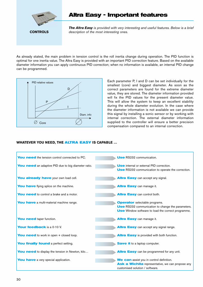
Altra Easy configuration options
Load Cell Control
Load Cells measure the force in the web and compare that force to the set point tension in the controller.
If there is any variation, the controller automatically increases or decreases the output, thus maintaining constant tension.
Dancer Control
The Dancer indicates a position error which is proportional to the web tension, and the controller compares that position to the set point within the controller. If there is any variation the controller automatically increases or decreases the output, thus maintaining constant tension.
Ultrasonics
Can be used in open or closed loop mode with the controller.
The signal from the ultrasonic device is used to measure the diameter of the reel.
The Altra Easy is provided with very interesting and useful features. Below is a brief description of the most interesting ones.CONTROLS
Altra Easy - Important features
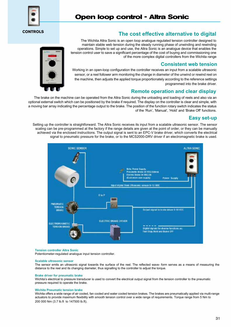
As already stated, the main problem in tension control is the roll inertia change during operation. The PID function is optimal for one inertia value. The Altra Easy is provided with an important PID correction feature. Based on the available diameter information you can apply continuous PID correction; when no information is available, an internal PID change can be programmed.
Each parameter P, I and D can be set individually for the smallest (core) and biggest diameter. As soon as the correct parameters are found for the extreme diameter value, they are stored. The diameter information provided will fix the PID values for the present diameter value. This will allow the system to keep an excellent stability during the whole diameter evolution. In the case where the diameter information is not available we can provide this signal by installing a sonic sensor or by working with internal correction. The external diameter information supplied to the controller will ensure a better precision compensation compared to an internal correction.
WHATEVER YOU NEED, THE ALTRA EASY IS CAPABLE …
D
I
P
Core
Diam. info
PID relative values
You need the tension control connected to PC. Use RS232 communication.
You need an adaptive PID due to big diameter ratio. Use internal or external PID correction. Use RS232 communication to operate the correction.
You already have your own load cell. Altra Easy can accept any signal.
You have flying splice on the machine. Altra Easy can manage it.
You need to control a brake and a motor. Altra Easy can control both.
You have a multi-material machine range. Operator selectable programs. Use RS232 communication to change the parameters. Use Window software to load the correct programme.
You need taper function. Altra Easy can manage it.
Your feedback is a 0-10 V. Altra Easy can accept any signal range.
You need to work in open + closed loop. Altra Easy is provided with both function.
You finally found a perfect setting. Save it to a laptop computer.
You need to display the tension in Newton, kilo… Altra Easy can be programmed for any unit.
You have a very special application. We can assist you in control definition. Ask a Wichita representative, we can propose any customised solution / software.
30
CONTROLS
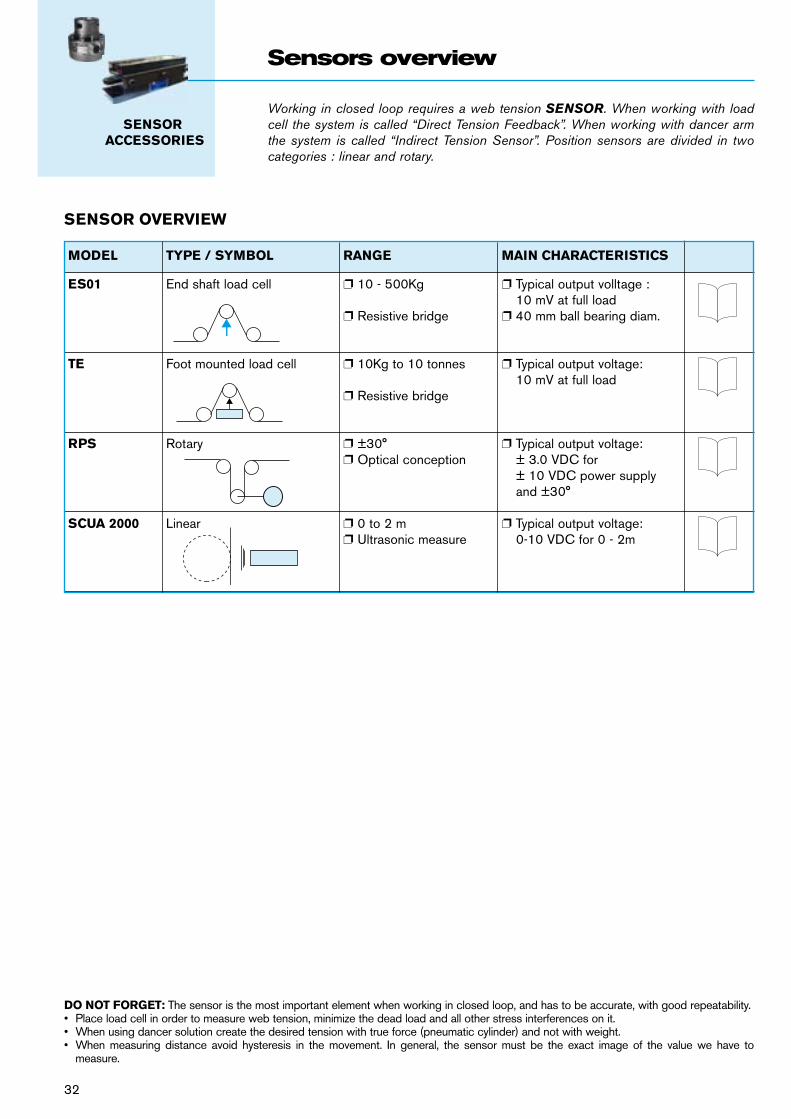
Open loop control - Altra Sonic
The Wichita Altra Sonic is an open loop analogue regulated tension controller designed to maintain stable web tension during the steady running phase of unwinding and rewinding
operations. Simple to set up and use, the Altra Sonic is an analogue device that enables the tension control user to save a significant percentage of the cost of buying and commissioning one
of the more complex digital controllers from the Wichita range
Consistent web tensionWorking in an open-loop configuration the controller receives an input from a scalable ultrasonic
sensor, or a reel follower arm monitoring the change in diameter of the unwind or rewind reel onthe machine, then adjusts the applied torque proportionately according to the reference settings
programmed into the brake driver.
Remote operation and clear displayThe brake on the machine can be operated from the Altra Sonic during the unloading and loading of reels and also via an
optional external switch which can be positioned by the brake if required. The display on the controller is clear and simple, witha moving bar array indicating the percentage output to the brake. The position of the function rotary switch indicates the status
of the ‘Run’, ‘Manual’, ‘Hold’ and ‘Brake Off’ functions.
Easy set-upSetting up the controller is straightforward. The Altra Sonic receives its input from a scalable ultrasonic sensor. The sensor
scaling can be pre-programmed at the factory if the range details are given at the point of order, or they can be manually achieved via the enclosed instructions. The output signal is sent to an EPC-V brake driver, which converts the electrical
signal to pneumatic pressure for the brake, or to the MCS2000-DRV driver if an electromagnetic brake is used.
The cost effective alternative to digital
Tension controller Altra SonicPotentiometer-regulated analogue input tension controller.
Scalable ultrasonic sensorThe sensor emits an ultrasonic signal towards the surface of the reel. The reflected wave- form serves as a means of measuring thedistance to the reel and its changing diameter, thus signalling to the controller to adjust the torque.
Brake driver for pneumatic brakeWichita’s electrical to pressure transducer is used to convert the electrical output signal from the tension controller to the pneumatic pressure required to operate the brake.
Wichita Pneumatic tension brakeWichita offers a wide range of air cooled, fan cooled and water cooled tension brakes. The brakes are pneumatically applied via multi-rangeactuators to provide maximum flexibility with smooth tension control over a wide range of requirements. Torque range from 5 Nm to 200 000 Nm (3.7 lb.ft to 147500 lb.ft).
Electromagnetic brakeFor installations with an electromagnetic brake, the ‘TB’ range of single disc tension brakes with a torque range of 0.5 Nm to 300 Nm (0.37lb.ft to 220lb.ft) is the preferred option. 31
Working in closed loop requires a web tension SENSOR. When working with load cell the system is called “Direct Tension Feedback”. When working with dancer arm the system is called “Indirect Tension Sensor”. Position sensors are divided in two categories : linear and rotary.
SENSOR ACCESSORIES
Sensors overview
SENSOR OVERVIEW
DO NOT FORGET: The sensor is the most important element when working in closed loop, and has to be accurate, with good repeatability.• Place load cell in order to measure web tension, minimize the dead load and all other stress interferences on it.• When using dancer solution create the desired tension with true force (pneumatic cylinder) and not with weight.• When measuring distance avoid hysteresis in the movement. In general, the sensor must be the exact image of the value we have to
measure.
MODEL TYPE / SYMBOL RANGE MAIN CHARACTERISTICS
ES01 End shaft load cell p 10 - 500Kg p Typical output volltage : 10 mV at full load p Resistive bridge p 40 mm ball bearing diam.
TE Foot mounted load cell p 10Kg to 10 tonnes p Typical output voltage: 10 mV at full load p Resistive bridge
RPS Rotary p ±30° p Typical output voltage: p Optical conception ± 3.0 VDC for ± 10 VDC power supply and ±30°
SCUA 2000 Linear p 0 to 2 m p Typical output voltage: p Ultrasonic measure 0-10 VDC for 0 - 2m
32
33
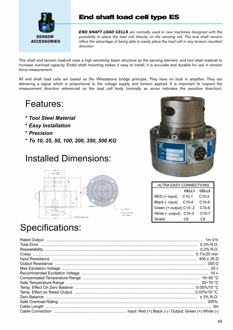
END ShAFT LOAD CELLS are normally used in new machines designed with the possibility to place the load cell directly on the sensing roll. The end shaft version offers the advantage of being able to easily place the load cell in any tension resultant direction.
SENSOR ACCESSORIES
End shaft load cell type ES
This shaft end tension loadcell uses a high sensitivity beam structure as the sensing element, and tool steel material to increase overload capacity. Endof shaft mounting makes it easy to install; it is accurate and durable for use in tensionforce measurement.
All end shaft load cells are based on the Wheatstone bridge principle. They have no built in amplifier. They are delivering a signal which is proportional to the voltage supply and tension applied. It is important to respect the measurement direction referenced on the load cell body (normally an arrow indicates the sensitive direction).
Features:* Tool Steel Material* Easy Installation* Precision* To 10, 25, 50, 100, 200, 350, 500 KG
Installed Dimensions:
Speci cations:Rated Output ............................................................................................................................................... 1m V/VTotal Error ............................................................................................................................................... 0.3% R.O.Repeatability ............................................................................................................................................ 0.2% R.O.Creep .................................................................................................................................................. 0.1%/20 minInput Resistance .................................................................................................................................... 405 ± 25 Output Resistance ......................................................................................................................................... 350 Max Excitation Voltage ..................................................................................................................................... 20 vRecommended Excitation Voltage ................................................................................................................... 10 vCompensated Temperature Range .......................................................................................................... 10~50 °CSafe Temperature Range ......................................................................................................................... 20~70 °CTemp. Effect On Zero Balance ............................................................................................................ 0.05%/10 °CTemp. Effect on Rated Output ..............................................................................................................0.03%/10 °CZero Balance .......................................................................................................................................... ± 3% R.O.Safe Overload Rating .................................................................................................................................... 300%Cable Length ...................................................................................................................................................... 3mCable Connection .................................................................. Input: Red (+) Black (-) / Output: Green (+) White (-)
ALTRA EASY CONNECTIONSCELL1 CELL2
RED (+ input) C10-1 C10-5Black (- input) C10-4 C10-8Green (+ output) C10- 2 C10-6White (- output) C10-3 C10-7Shield C9 C9
34
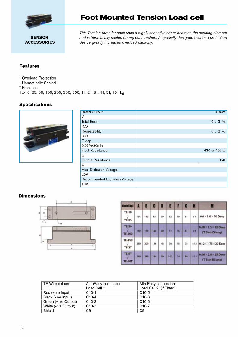
This Tension force loadcell uses a highly sensetive shear beam as the sensing element and is hermitically sealed during construction. A specially designed overload protection device greatly increases overload capacity.
SENSOR ACCESSORIES
Foot Mounted Tension Load cell
SpecificationsRated Output 1 mV/VTotal Error 0 . 3 % R.O.Repeatability 0 . 2 % R.O.Creep 0.05%/20minInput Resistance 430 or 405 ± ΩOutput Resistance 350 ΩMax. Excitation Voltage 20VRecommended Excitation Voltage 10V
Features
* Overload Protection* Hermetically Sealed* PrecisionTE-10, 25, 50, 100, 200, 350, 500, 1T, 2T, 3T, 4T, 5T, 10T kg
Dimensions
TE Wire colours AltraEasy connection Load Cell 1
AltraEasy connection Load Cell 2, (if Fitted).
Red (+ ve Input) C10-1 C10-5 Black (- ve Input) C10-4 C10-8 Green (+ ve Output) C10-2 C10-6 White (- ve Output) C10-3 C10-7 Shield C9 C9
35
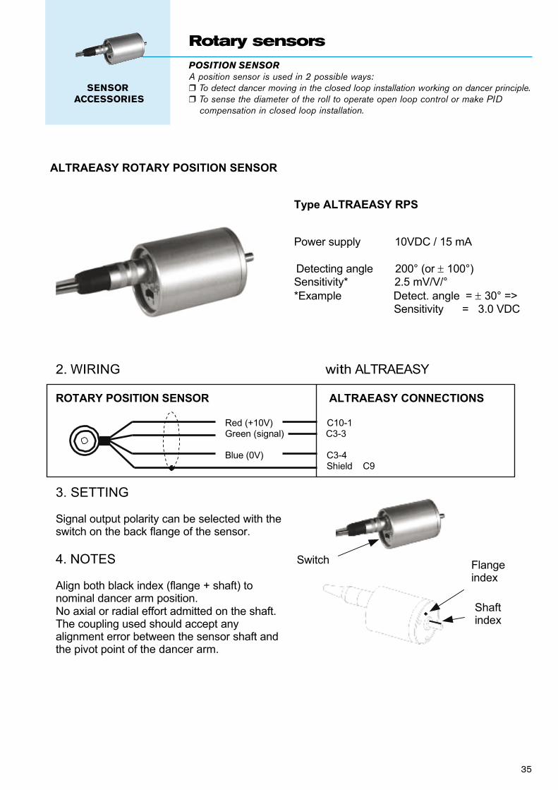
POSITION SENSORA position sensor is used in 2 possible ways:r To detect dancer moving in the closed loop installation working on dancer principle.r To sense the diameter of the roll to operate open loop control or make PID
compensation in closed loop installation.
SENSOR ACCESSORIES
Rotary sensors
1 of 2
Wichita Company Ltd Ampthill Road Bedford MK42 9RD, UK tel. +44 (0)1234 350 311 fax +44 (0)1234 350 317 www wichita.co.uk
MOUNTING INSTRUCTIONS
27/06/2008
ALTRAEASY ROTARY POSITION SENSOR
Type ALTRAEASY RPS
Power supply 10VDC / 15 mA
Detecting angle 200° (or 100°) Sensitivity* 2.5 mV/V/° *Example Detect. angle = 30° =>
Sensitivity = 3.0 VDC
2. WIRING with ALTRAEASY
ROTARY POSITION SENSOR ALTRAEASY CONNECTIONS
Red (+10V) C10-1 Green (signal) C3-3 Blue (0V) C3-4 Shield C9
3. SETTING
Signal output polarity can be selected with the switch on the back flange of the sensor.
4. NOTES
Align both black index (flange + shaft) to nominal dancer arm position. No axial or radial effort admitted on the shaft. The coupling used should accept any alignment error between the sensor shaft and the pivot point of the dancer arm.
Switch Flangeindex
Shaftindex
50,8
130
65 18
min 47 / max 70
ø38,1
3 x ø45
5757
3 x
120°
Coupling
ø6,3
5
45
21,9 14,2
38,
1
ø6,5
31,6
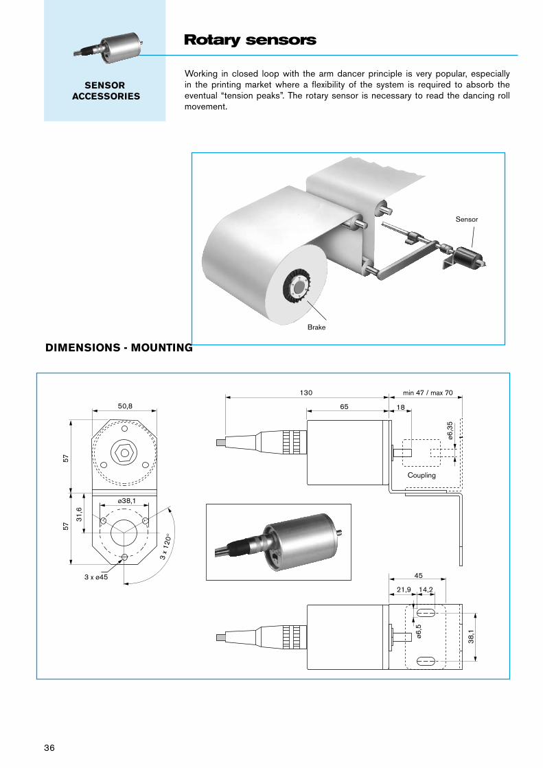
Brake
Sensor
Working in closed loop with the arm dancer principle is very popular, especially in the printing market where a flexibility of the system is required to absorb the eventual “tension peaks”. The rotary sensor is necessary to read the dancing roll movement.
DIMENSIONS - MOUNTING
SENSOR ACCESSORIES
Rotary sensors
36
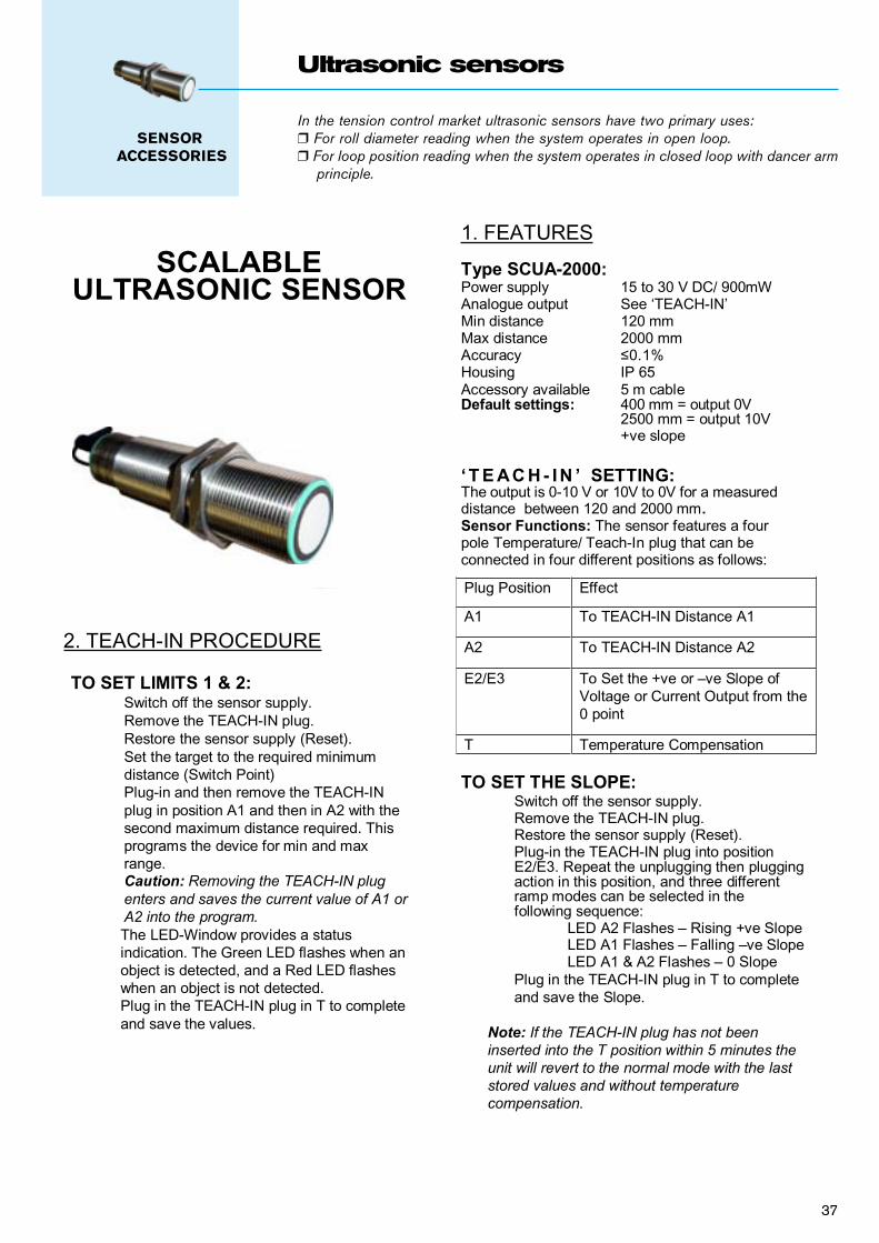
In the tension control market ultrasonic sensors have two primary uses:r For roll diameter reading when the system operates in open loop.r For loop position reading when the system operates in closed loop with dancer arm principle.
SENSOR ACCESSORIES
Ultrasonic sensors
E.D.S. 7.2.2 Page 1 of 3Issue 1 – 27/07/2006
WICHITA Co. Ltd.Ampthill Road,Bedford
MK42 9RDtel. +44 (0)1234 0311
fax. +44 (0)1234 [email protected]
www.wichita.co.uk
MOUNTING INSTRUCTIONS–
SCALABLEULTRASONIC SENSOR
2. TEACH-IN PROCEDURE
TO SET LIMITS 1 & 2:Switch off the sensor supply.Remove the TEACH-IN plug.Restore the sensor supply (Reset).Set the target to the required minimumdistance (Switch Point)Plug-in and then remove the TEACH-INplug in position A1 and then in A2 with thesecond maximum distance required. Thisprograms the device for min and maxrange.Caution: Removing the TEACH-IN plugenters and saves the current value of A1 orA2 into the program.The LED-Window provides a statusindication. The Green LED flashes when anobject is detected, and a Red LED flasheswhen an object is not detected.Plug in the TEACH-IN plug in T to completeand save the values.
1. FEATURES
Type SCUA-2000:Power supply 15 to 30 V DC/ 900mWAnalogue output See ‘TEACH-IN’Min distance 120 mmMax distance 2000 mmAccuracy 0.1%Housing IP 65Accessory available 5 m cableDefault settings: 400 mm = output 0V 2500 mm = output 10V
+ve slope
‘ T E AC H - IN ’ SETTING:The output is 0-10 V or 10V to 0V for a measureddistance between 120 and 2000 mm.Sensor Functions: The sensor features a fourpole Temperature/ Teach-In plug that can beconnected in four different positions as follows:
TO SET THE SLOPE:Switch off the sensor supply.Remove the TEACH-IN plug.Restore the sensor supply (Reset).Plug-in the TEACH-IN plug into positionE2/E3. Repeat the unplugging then pluggingaction in this position, and three differentramp modes can be selected in thefollowing sequence:
LED A2 Flashes – Rising +ve SlopeLED A1 Flashes – Falling –ve SlopeLED A1 & A2 Flashes – 0 Slope
Plug in the TEACH-IN plug in T to completeand save the Slope.
Note: If the TEACH-IN plug has not beeninserted into the T position within 5 minutes theunit will revert to the normal mode with the laststored values and without temperaturecompensation.
Plug Position Effect
A1 To TEACH-IN Distance A1
A2 To TEACH-IN Distance A2
E2/E3 To Set the +ve or –ve Slope ofVoltage or Current Output from the0 point
T Temperature Compensation
37
E.D.S. 7.2.2 Page 1 of 3Issue 1 – 27/07/2006
WICHITA Co. Ltd.Ampthill Road,Bedford
MK42 9RDtel. +44 (0)1234 0311
fax. +44 (0)1234 [email protected]
www.wichita.co.uk
MOUNTING INSTRUCTIONS–
SCALABLEULTRASONIC SENSOR
2. TEACH-IN PROCEDURE
TO SET LIMITS 1 & 2:Switch off the sensor supply.Remove the TEACH-IN plug.Restore the sensor supply (Reset).Set the target to the required minimumdistance (Switch Point)Plug-in and then remove the TEACH-INplug in position A1 and then in A2 with thesecond maximum distance required. Thisprograms the device for min and maxrange.Caution: Removing the TEACH-IN plugenters and saves the current value of A1 orA2 into the program.The LED-Window provides a statusindication. The Green LED flashes when anobject is detected, and a Red LED flasheswhen an object is not detected.Plug in the TEACH-IN plug in T to completeand save the values.
1. FEATURES
Type SCUA-2000:Power supply 15 to 30 V DC/ 900mWAnalogue output See ‘TEACH-IN’Min distance 120 mmMax distance 2000 mmAccuracy 0.1%Housing IP 65Accessory available 5 m cableDefault settings: 400 mm = output 0V 2500 mm = output 10V
+ve slope
‘ T E AC H - IN ’ SETTING:The output is 0-10 V or 10V to 0V for a measureddistance between 120 and 2000 mm.Sensor Functions: The sensor features a fourpole Temperature/ Teach-In plug that can beconnected in four different positions as follows:
TO SET THE SLOPE:Switch off the sensor supply.Remove the TEACH-IN plug.Restore the sensor supply (Reset).Plug-in the TEACH-IN plug into positionE2/E3. Repeat the unplugging then pluggingaction in this position, and three differentramp modes can be selected in thefollowing sequence:
LED A2 Flashes – Rising +ve SlopeLED A1 Flashes – Falling –ve SlopeLED A1 & A2 Flashes – 0 Slope
Plug in the TEACH-IN plug in T to completeand save the Slope.
Note: If the TEACH-IN plug has not beeninserted into the T position within 5 minutes theunit will revert to the normal mode with the laststored values and without temperaturecompensation.
Plug Position Effect
A1 To TEACH-IN Distance A1
A2 To TEACH-IN Distance A2
E2/E3 To Set the +ve or –ve Slope ofVoltage or Current Output from the0 point
T Temperature Compensation
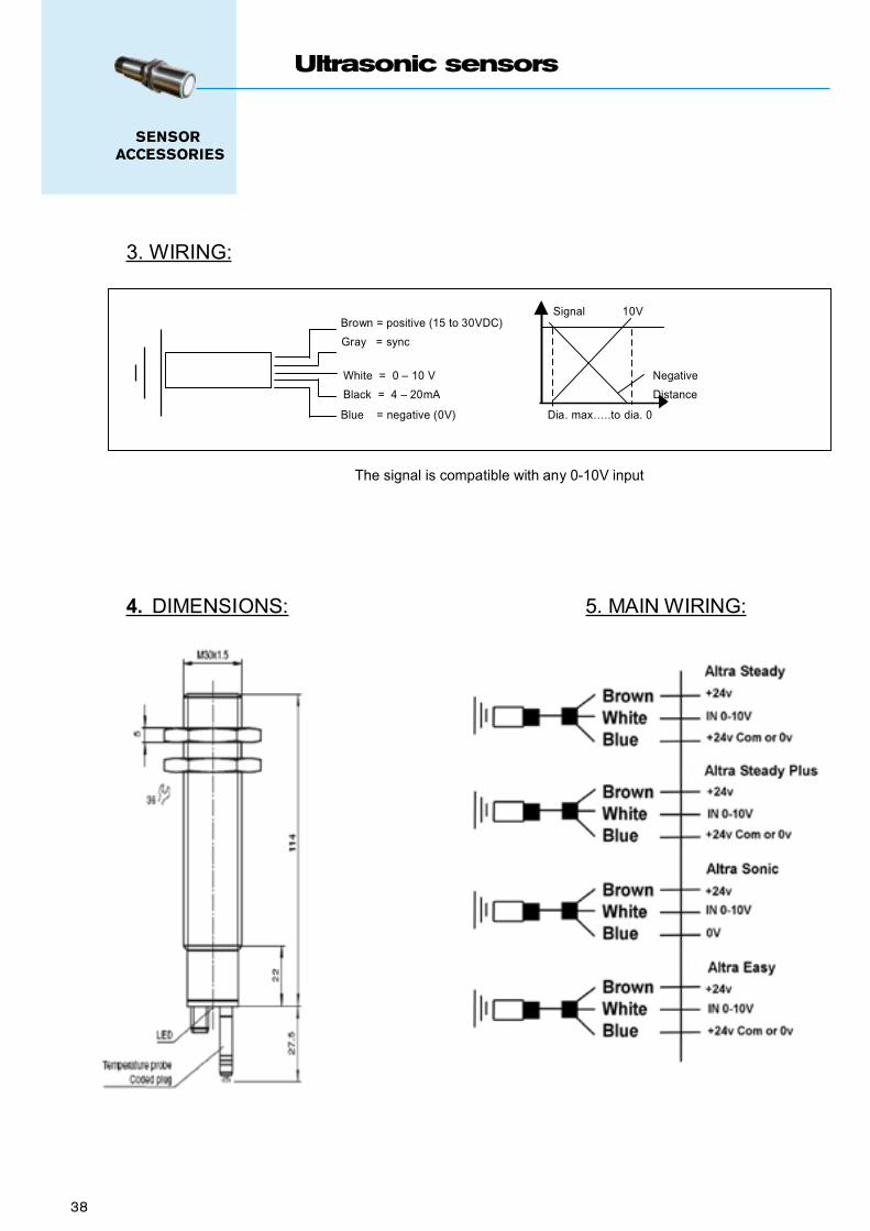
38 E.D.S. 7.2.2 Page 2 of 3Issue 1 – 27/07/2006
WICHITA Co. Ltd.Ampthill Road,Bedford
MK42 9RDtel. +44 (0)1234 0311
fax. +44 (0)1234 [email protected]
www.wichita.co.uk
3. WIRING:
Signal 10VBrown = positive (15 to 30VDC)
Gray = sync
White = 0 – 10 V Negative
Black = 4 – 20mA Distance
Blue = negative (0V) Dia. max…..to dia. 0
The signal is compatible with any 0-10V input
4. DIMENSIONS: 5. MAIN WIRING:
SENSOR ACCESSORIES
Ultrasonic sensors
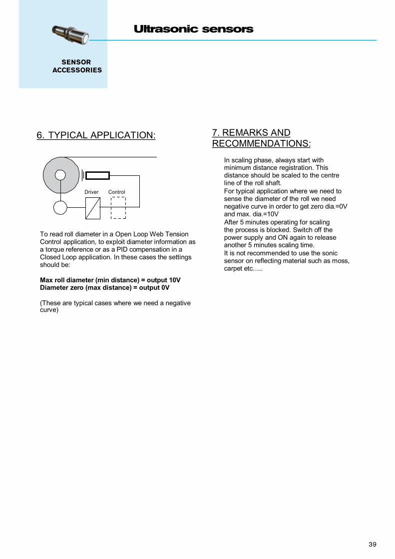
SENSOR ACCESSORIES
Ultrasonic sensors
E.D.S. 7.2.2 Page 3 of 3Issue 1 – 27/07/2006
WICHITA Co. Ltd.Ampthill Road,Bedford
MK42 9RDtel. +44 (0)1234 0311
fax. +44 (0)1234 [email protected]
www.wichita.co.uk
6. TYPICAL APPLICATION:
Driver Control
To read roll diameter in a Open Loop Web TensionControl application, to exploit diameter information asa torque reference or as a PID compensation in aClosed Loop application. In these cases the settingsshould be:
Max roll diameter (min distance) = output 10VDiameter zero (max distance) = output 0V
(These are typical cases where we need a negativecurve)
7. REMARKS ANDRECOMMENDATIONS:
In scaling phase, always start withminimum distance registration. Thisdistance should be scaled to the centreline of the roll shaft.For typical application where we need tosense the diameter of the roll we neednegative curve in order to get zero dia.=0Vand max. dia.=10VAfter 5 minutes operating for scalingthe process is blocked. Switch off thepower supply and ON again to releaseanother 5 minutes scaling time.It is not recommended to use the sonicsensor on reflecting material such as moss,carpet etc…..
39
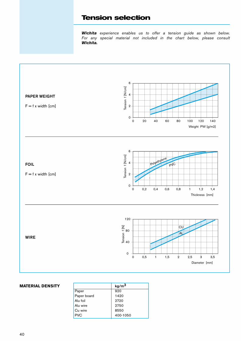
40
Wichita experience enables us to offer a tension guide as shown below. For any special material not included in the chart below, please consult Wichita.
Tension selection
AL
CU
PVCPolyethylene
6
4
2
00 20 40 60 80 100 120 140
Tens
ion
f [N
/cm
]Weight PW [g/m2]
6
4
2
00 0,2 0,4 0,6 0,8 1 1,2 1,4
Tens
ion
f [N
/cm
]
Thickness [mm]
Diameter [mm]
120
80
40
00 0,5 1 1,5 2 2,5 3 3,5
Tens
ion
f [N
]
AL
CU
PVCPolyethylene
6
4
2
00 20 40 60 80 100 120 140
Tens
ion
f [N
/cm
]Weight PW [g/m2]
6
4
2
00 0,2 0,4 0,6 0,8 1 1,2 1,4
Tens
ion
f [N
/cm
]
Thickness [mm]
Diameter [mm]
120
80
40
00 0,5 1 1,5 2 2,5 3 3,5
Tens
ion
f [N
]
AL
CU
PVCPolyethylene
6
4
2
00 20 40 60 80 100 120 140
Tens
ion
f [N
/cm
]
Weight PW [g/m2]
6
4
2
00 0,2 0,4 0,6 0,8 1 1,2 1,4
Tens
ion
f [N
/cm
]
Thickness [mm]
Diameter [mm]
120
80
40
00 0,5 1 1,5 2 2,5 3 3,5
Tens
ion
f [N
]
PAPER WEIGHT
F = f x width [cm]
FOIL
F = f x width [cm]
WIRE
MATERIAL DENSITY kg/m3
Paper 920Paper board 1420Alu foil 2720Alu wire 2750Cu wire 8550PVC 400-1050

To enable us to assist you in selecting the best product type and specification to ensure reliable and accurate tension control, please submit this APPLICATION FORM.
Data application Form
Unwider stand Nip roll Rewind stand
Which type of machine is it ?♦ Printer, Slitter, Sheeter, Coater, Laminator, …or other ?Which machine part concerned Which web material is it ? Max / min tension (if known)
Characteristics of the material ♦ Paper weight Gr / m2
♦ Plastic film thickness mm♦ Wire diameter, matter mm♦ Other (short description) Characteristics machine ♦ Auto flying splice Yes / No♦ Zero speed splice Yes / No♦ Max linear speed M / min♦ Min linear speed M / min♦ Max acceleration time M / min / sec♦ Normal deceleration time M / min / sec♦ Emergency stop time M / min / sec♦ Taper tension requested + or - % Roll characteristics ♦ Weight Kg♦ Max diameter mm♦ Min diameter mm♦ Max width mm♦ Min width mm General information ♦ Is it a new project or a retrofit ? ♦ Loosing tension permitted in Yes / No emergency stop case ♦ If machine working in cycle, Time in sec. what’s the cycle rate ? Speed in m/min♦ Is the brake or motor direct Roll/ brake on shaft or gear mounted ? (rpm)♦ Which control configuration ? Open loop / Closed loop
Please complete this form as much as possible. Please also include any other information of interest.
Speed
Time
Max speed
Company name:
Adresse:
City: Country:
Contact name: Phone / fax:
41


India – Francis Klein & Co. Pvt. Ltd.Tel: + 91 2053 39770 Fax: + 91 2055 39771Email: [email protected] – Warner Electric Singapore Pte. Ltd. Tel: + 65 6487 4464 Fax : + 65 6487 6674Email: [email protected] – Larom MarketingTel: + 97 2499 37333 Fax: + 97 2505 239552Email: [email protected] – Bianchi Cuscinetti, Trasmissioni ETel: + 39 0267 861 Fax: 39 0267 01062Email: [email protected] – Japan Wichita Co LtdTel: + 81 3345 61461 Fax: + 81 3345 61484Email: [email protected] – Warner Electric Singapore Pte. Ltd.Tel: + 65 6487 4464 Fax : + 65 6487 6674Email : [email protected] Zealand – Warner Electric AustraliaTel: + 64 9268 2600 Fax: + 64 9268 3601Email: [email protected] – Betamo ASTel: + 47 6927 5510 Fax: + 47 6927 4550Email: [email protected] – Stemin Machinefabriek b.v.Tel. +31 573 252 043 fax +31 573 257 113Email: [email protected] – Warner Electric Singapore Pte. Ltd.Tel: + 65 6487 4464 Fax : + 65 6487 6674Email: [email protected] – Bibus Menos Sp. z.o.o.Tel: + 48 5866 09570 Fax: + 48 5866 17132Email: [email protected] – Pinhol Gomes & Gomes LdaTel: + 35 1214 256850 Fax: + 35 1214 256859Email: [email protected] of South Africa – SintechTel: + 27 11823 2359 Fax: + 27 11 823 2387Email: [email protected]
Singapore – Warner Electric Singapore Pte. Ltd. Tel: + 65 6487 4464 Fax : + 65 6487 6674Email: [email protected]
Australia – Warner Electric AustraliaTel: + 61 2989 40133 Fax: + 61 2989 40368Email: [email protected] – Bibus Austria GmbHTel: + 43 2242 33388 Fax: + 43 2242 33388Email: [email protected] - A.Z. Hollink b.v.b.a.Tel: +32 3722 1118 Fax: +32 3722 1119Email: [email protected] Republic – Bibus s.r.o.Tel: + 420 5471 25300 Fax: + 420 5471 25310Email: [email protected] –AVN Automation ASTel: + 45 7020 0411 Fax: + 45 8722 8100Email: [email protected] – ItacoTel: + 20 2272 5754 Fax: + 20 2273 7245Email: [email protected] – Torsion DynamicsTel: + 35 3184 61677 Fax: + 35 3184 61688Email: [email protected] – Knorring Oy AbTel: + 358 9 56 041 Fax: + 358 9 565 2463Email: [email protected] – FogexTel: +33 1 3434 4600 Fax: +33 1 3434 4601Email: [email protected] – Wichita Company LimitedTel: + 33 4503 25226 Fax: +33 4503 25227Email: [email protected] Germany – Warner Electric Verwaltungs GmbHTel: + 49 6221 3047 Fax: + 49 6221 3047 17Email: [email protected] – Dimitrious DeliyiannisTel: + 30 1061 08581 Fax: 30 1061 08583Email: [email protected] Kong – Warner Shui-Hing Ltd.Tel: + 85 2261 59313 Fax: + 85 2261 59162Email: [email protected] – Bibus KftTel: + 36 1265 2733 Fax: + 36 1264 8900Email: [email protected]
Russia - Bibus o.o.o. Tel: +7 812 251 6271 Fax: +7 812 251 9014Email: [email protected] Russia - Bibus Romania SESSRLTel: +4 0265 200500 Fax: +4 0256 220666Email: [email protected] – Bibus SK s.r.o.Tel: +38 513818004 Fax: + 38 513818005Email: [email protected] – Sociedad Ind. de Transmisiones SA (SIT)Tel: + 34 9434 57200 Fax: + 34 9434 63356Email: [email protected] Korea – Warner Electric Singapore Pte. Ltd. Tel: + 65 6487 4464 Fax : + 65 6487 6674Email: [email protected] – Lonne Scandinavia ABTel: +46 (0) 4238 0300 Fax: +46 (0) 4238 0309Email: [email protected] Switzerland – Laesser AGTel: + 41 6279 16841 Fax: + 41 6279 13903Email: [email protected] – Warner Electric (Taiwan) Ltd.Tel: + 88 6225 778156 Fax: + 88 6225 706358Email: [email protected] – Warner Electric (Thailand) Ltd.Tel: + 66 2322 5527 Fax: + 66 2320 2380Email: [email protected] – Ost Olgun Dis Ticaret AS1.5Tel: + 90 2122 460136 Fax: + 90 2122 479739Email: [email protected] States of America – Warner Electric U.S.A.Tel: + 1 815 389 3771 Fax: + 1 815 389 2582Email: [email protected] States of America – Industrial ClutchTel: + 1 262 547 3357 Fax: + 1 262 547 2949Email: [email protected]
Worldwide distributorsWorldwide support and distribution