Embed Size (px)
Citation preview
ISSN 1520-295X
Tension, Compression and Cyclic Testing ofEngineered Cementitious Composite Materials
by
Keith Kesner and Sarah L. BillingtonCornell University
School of Civil and Environmental EngineeringIthaca, New York 14853
Technical Report MCEER-04-0002
March 1, 2004
This research was conducted at Cornell University and was supported primarilyby the Earthquake Engineering Research Centers Program of the National Science Foundation
under award number EEC-9701471.

NOTICEThis report was prepared by Cornell University as a result of research sponsoredby the Multidisciplinary Center for Earthquake Engineering Research (MCEER)through a grant from the Earthquake Engineering Research Centers Program ofthe National Science Foundation under NSF award number EEC-9701471 and othersponsors. Neither MCEER, associates of MCEER, its sponsors, Cornell University,nor any person acting on their behalf:
a. makes any warranty, express or implied, with respect to the use of any infor-mation, apparatus, method, or process disclosed in this report or that such usemay not infringe upon privately owned rights; or
b. assumes any liabilities of whatsoever kind with respect to the use of, or thedamage resulting from the use of, any information, apparatus, method, or pro-cess disclosed in this report.
Any opinions, findings, and conclusions or recommendations expressed in thispublication are those of the author(s) and do not necessarily reflect the views ofMCEER, the National Science Foundation, or other sponsors.
Tension, Compression and Cyclic Testing ofEngineered Cementitious Composite Materials
by
Keith Kesner1 and Sarah L. Billington2
Publication Date: March 1, 2004Submittal Date: August 7, 2003
Technical Report MCEER-04-0002
NSF Master Contract Number EEC-9701471
1 Instructor, School of Civil and Enviromental Engineering, Cornell University2 Clare Boothe Luce Assistant Professor, Department of Civil and Environmental Engineering,
Stanford University; former Assistant Professor, School of Civil and Enviromental Engineer-ing, Cornell University
MULTIDISCIPLINARY CENTER FOR EARTHQUAKE ENGINEERING RESEARCHUniversity at Buffalo, State University of New YorkRed Jacket Quadrangle, Buffalo, NY 14261

iii
Preface
The Multidisciplinary Center for Earthquake Engineering Research (MCEER) is a national center ofexcellence in advanced technology applications that is dedicated to the reduction of earthquake lossesnationwide. Headquartered at the University at Buffalo, State University of New York, the Centerwas originally established by the National Science Foundation in 1986, as the National Center forEarthquake Engineering Research (NCEER).
Comprising a consortium of researchers from numerous disciplines and institutions throughout theUnited States, the Center’s mission is to reduce earthquake losses through research and theapplication of advanced technologies that improve engineering, pre-earthquake planning and post-earthquake recovery strategies. Toward this end, the Center coordinates a nationwide program ofmultidisciplinary team research, education and outreach activities.
MCEER’s research is conducted under the sponsorship of two major federal agencies: the NationalScience Foundation (NSF) and the Federal Highway Administration (FHWA), and the State of NewYork. Significant support is derived from the Federal Emergency Management Agency (FEMA),other state governments, academic institutions, foreign governments and private industry.
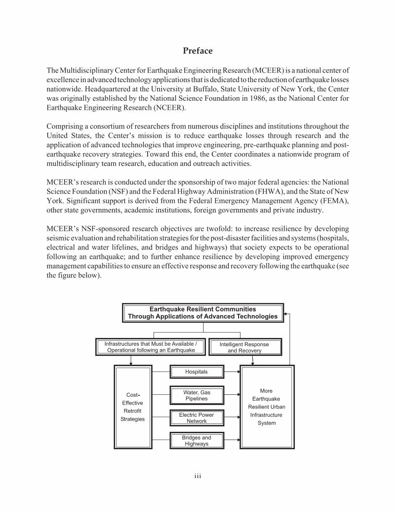
MCEER’s NSF-sponsored research objectives are twofold: to increase resilience by developingseismic evaluation and rehabilitation strategies for the post-disaster facilities and systems (hospitals,electrical and water lifelines, and bridges and highways) that society expects to be operationalfollowing an earthquake; and to further enhance resilience by developing improved emergencymanagement capabilities to ensure an effective response and recovery following the earthquake (seethe figure below).
-
Infrastructures that Must be Available /Operational following an Earthquake
Intelligent Responseand Recovery
Hospitals
Water, GasPipelines
Electric PowerNetwork
Bridges andHighways
More
Earthquake
Resilient Urban
Infrastructure
System
Cost-
Effective
Retrofit
Strategies
Earthquake Resilient CommunitiesThrough Applications of Advanced Technologies
iv
A cross-program activity focuses on the establishment of an effective experimental and analyticalnetwork to facilitate the exchange of information between researchers located in various institutionsacross the country. These are complemented by, and integrated with, other MCEER activities ineducation, outreach, technology transfer, and industry partnerships.
The study described in this report describes the testing performed to examine the potential use andbehavior of engineered cementitious composite (ECC) materials in lieu of traditional materials. Thematerials are proposed for use in seismic strengthening and retrofit applications. Specifically, aninfill panel system was developed that uses the pseudo-strain hardening properties of the ECCmaterials. Laboratory studies examined the effect of different curing and drying times, the tensileresponse of different specimen geometries, and the response of ECC materials to reversed cyclicloadings. The ECC materials investigated showed a wide range of tensile properties as a functionof specimen geometry and constituent materials. Other key findings are summarized in theConclusions section of the report. This study is the first to investigate the response of the ECCmaterials to reversed cyclic loadings.

v
ABSTRACT
The research presented herein describes the testing performed to examine the potential use of engineered cementitious composite (ECC) materials in lieu of traditional materials. The materials are proposed for use in seismic strengthening and retrofit applications. Specifically an infill panel system is developed that utilizes the pseudo-strain hardening properties of the ECC materials. Laboratory studies were used to examine the effect of different curing and drying times, the tensile response of different specimen geometries, and the response of ECC materials to reversed cyclic loadings. The examination of curing and drying times indicated that extended wet curing periods, followed by a drying period were needed to optimize the tensile strain capacity of the material. Significant variations in tensile strain capacity were observed with different specimen geometries. The cyclic testing results indicated the ECC materials have a unique response to cyclic loadings with the stiffness of the material varying with the applied strain and loading history.

vii
TABLE OF CONTENTS
SECTION TITLE PAGE Section 1 Introduction and Overview 1.0 Introduction 1 1.1 Overview 2 Section 2 ECC Materials Literature Review 2.0 Introduction 3 2.1 ECC Material Behavior 3 2.1.1 Fiber Pullout Behavior 4 2.1.2 Steady-State Cracking 7 2.1.3 Compressive Response of ECC Materials 10 2.1.4 Cyclic Response of ECC Materials 10 2.1.5 Use of Aggregates in ECC Materials 10 2.1.6 Fiber Treatments 11 2.2 Comparisons to Other Cementitious Composite Materials 11 2.2.1 SIFCON/SIMCON 12 2.2.2 HPMFRCC 12 2.3 ECC Applications 13 2.3.1 Protective Applications 13 2.3.2 Structural Applications 14 2.4 Summary and Discussion 17 Section 3 ECC Material Testing and Behavior 3.0 Introduction 19 3.1 Evaluation of Curing and Drying Periods 19 3.1.1 Test Series 20 3.1.2 ECC Casting 21 3.1.3 ECC Tensile Testing Set-up and Protocol 22 3.1.4 Testing Results 23 3.1.5 Discussion of Test Results 27 3.1.6 Summary of Curing and Drying Study 28 3.2 Evaluation of Tensile Specimen Geometry 28 3.2.1 Test Series 29 3.2.2 Test Results 30 3.2.3 Discussion of Test Results 33 3.2.4 Summary of Test Results 34 3.3 Evaluation of Different Fibers in ECC Materials 34 3.3.1 Previous Work 34 3.3.2 Fibers Examined 34 3.3.3 ECC Mix Designs 35 3.3.4 Predicted Response 37
viii
TABLE OF CONTENTS (cont’d)
SECTION TITLE PAGE 3.3.5 Test Series 38 3.3.6 Test Results 38 3.3.7 Discussion of Test Results 45 3.3.8 Summary of Test Results 46 3.4 Cyclic Testing of ECC Materials 46 3.4.1 Previous Work 46 3.4.2 Test Program 47 3.4.3 Material Composition 47 3.4.4 Test Results - Monotonic Tension Testing 48 3.4.5 Test Results - Monotonic Compression Testing 49 3.4.6 Test Results - Cyclic Testing 54
Cyclic Compression 54 Cyclic Tension/Compression 59
3.4.7 Discussion of Cyclic Response 71 3.4.8 Cyclic Material Model Development 72 3.4.9 Summary of Cyclic Test Results 73 3.5 Implications for ECC Applications 73 3.6 Summary 74
Section 4 Summary and Conclusions 4.0 Summary 77 4.1 Conclusions 77 4.2 Recommendations for Future Work 78 Section 5 References 79
ix
LIST OF ILLUSTRATIONS FIGURE TITLE PAGE 2-1 (a) Comparison of stress / strain behavior of Portland
cement-based materials under uniaxial tension, (b) and multiple cracking exhibited by ECC materials 4
2-2 Schematic of fibers bridging crack 5 2-3 Shear lag analysis of fiber pullout from matrix.
(adapted from Marshall and Cox, 1985) 6 2-4 Schematic representation of trapped crack along ECC/concrete interface.
(Adopted from Lim and Li, 1998) 14 2-5 Schematic representation of ECC panel test (Adopted from
Kanda, et al. 1998.) 15 3-1 Effect of drying on tensile stress in cementitious material
(Adapted from van Mier, 1997) 20 3-2 Schematic of prismatic ECC tensile specimen 23 3-3 Comparison of tensile strain capacity from test series A, B and C 24 3-4 Comparison of specimen weights during drying period for tensile
specimens shown in Figure 3.3 25 3-5 Representative tensile test results from series D to H
26 3-6 Dogbone (a) and cylinder specimens (b) used in uniaxial tension
testing (Drawings not to scale) 29 3-7 Comparison of results from three different geometries 31 3-8 Uniaxial tensile test response of dogbone specimens 31 3-9 Uniaxial tensile test response of prism specimens 32 3-10 Uniaxial tensile test response of cylinder specimens 32 3-11 Comparison of uniaxial tensile test results from dogbone
specimens (Specimen SP-A stopped at 5% strain) 39 3-12 Comparison of uniaxial tensile test results from cylindrical specimens 39 3-13 Uniaxial tensile test response of dogbone specimens using SP-A
mix design (Stopped at 5% strain, however all specimens were softening) 40 3-14 Uniaxial tensile test response of dogbone specimens using
DYN-A mix design 40 3-15 Uniaxial tensile test response of dogbone specimens using
REC-A mix design 41 3-16 Uniaxial tensile test response of dogbone specimens using
RECS-A mix design 41 3-17 Uniaxial tensile test response of cylinder specimens using
SP-A mix design 42 3-18 Uniaxial tensile test response of cylinder specimens using
REC-A mix design 42 3-19 Uniaxial tensile test response of cylinder specimens using
RECS-A mix design 43
x
LIST OF ILLUSTRATIONS (cont’d) FIGURE TITLE PAGE 3-20 Uniaxial compressive test results from various mix designs 50 3-21 Uniaxial compressive response of mix SP 51 3-22 Uniaxial compressive response of mix SP –A 51 3-23 Uniaxial compressive response of mix Paste 52 3-24 Uniaxial compressive response of mix REC-A 52 3-25 Uniaxial compressive response of mix RECS-A 53 3-26 Uniaxial compressive response of mix Mortar 53 3-27 Cyclic compression response of mix design SP 54 3-28 Cyclic compression response of mix design SP-A 55 3-29 Cyclic compression response of mix design REC-A 55 3-30 Cyclic compression response of mix design RECS-A 56 3-31 Cyclic compression response of mix design Paste 56 3-32 Cyclic compression response of mix design Mortar 57 3-33 Comparison of cyclic and monotonic compression test results
from mix designs SP and SP-A 58 3-34 Comparison of cyclic and monotonic compression tests results
from mix design REC-A 59 3-35 Cyclic tension/compression response of SP mix design using
Y-R loading 60 3-36 Cyclic tension/compression response of SP-A mix design using
Y-R loading 61 3-37 Cyclic tension/compression response of REC-A mix design using
Y-R loading 62 3-38 Cyclic tension/compression response of RECS-A mix design
using Y-R loading 63 3-39 Result from Y-R loading on SP material (SP – 2) 64 3-40 Results from single cycle, with distinct regions highlighted 65 3-41 Cyclic tension compression response of SP mix design using
balanced loading scheme 66 3-42 Cyclic tension compression response of SP-A mix design using
balanced loading scheme 67 3-43 Cyclic tension compression response of RECS-A mix design
using balanced loading scheme 68 3-44 Typical result from a balanced loading test from mix design
SP (Specimen SP-2) 69 3-45 Close-up of tensile region shown in Figure 3.44, with uniaxial
tensile response added for comparison 70 3-46 Tensile localization in balanced loading specimen at location of
compressive damage 71 3-47 Typical orthogonal crack pattern in ECC materials observed
during cyclic loading 71
xi
LIST OF TABLES TABLE TITLE PAGE 2-1 Fiber Properties 9 3-1 Summary of curing and drying conditions evaluated 21 3-2 Mix designs used in testing 22 3-3 Summary of test results from series A, B and C 25 3-4 Summary of test results from sets D to H 27 3-5 Summary of test results from specimen geometry study 33 3-6 Summary of pertinent fiber characteristics 35 3-7 Mix designs used in the fiber evaluation testing 37 3-8 Summary of uniaxial tensile test results from dogbone specimens 44 3-9 Summary of uniaxial tensile test results from cylinder specimens 45 3-10 Mix designs used in the cyclic testing 48 3-11 Summary of Uniaxial Compression Test Results 49

1
Section 1 Introduction and Overview
1.0 Introduction The research presented herein focused on the development of an innovative composite material for use in seismic strengthening and rehabilitation applications. Specifically, engineered cementitious composite materials (ECC), which exhibit a pseudo strain-hardening response in tension were evaluated and found to have excellent potential for use in strengthening and rehabilitation applications. Continued development of these materials will give engineers greater flexibility to design and rehabilitate structures to withstand seismic and other types of loading. The following sections describe how applications that utilize these materials are developed for seismic strengthening and retrofit applications. The development of seismic strengthening and retrofit applications required the combination of several types of research. These included the use of small-scale laboratory testing both to evaluate the ECC material properties, specifically the response to reversed cyclic loadings, and to verify the micromechanical assumptions used in the development of the materials. These tests are described in this report. Numerical, finite element-based, simulations were performed using a material model developed from the cyclic laboratory test results. These simulations were used to model the performance of the ECC materials in structural retrofit applications. The numerical simulations were supported by large-scale laboratory tests that demonstrated the performance of the retrofits. These results are described in Kesner and Billington (2003). The primary goal of the research was the development of seismic retrofit strategies to improve the performance of structures during earthquakes. Within the broad concept of developing seismic retrofit strategies, there were two unique focus areas:
1. Utilize the unique properties of ECC materials in structural retrofit applications. 2. Development of retrofit strategies for critical structures such as hospitals.
The two areas of the research were essential in providing practical bounds to the research. The pseudo-strain hardening nature of the ECC materials, in combination with reinforcing steel, results in a material with the ability to both maintain structural capacity and integrity at higher tensile strain levels than traditional materials (Fisher and Li, 2001). The ability of the materials to maintain both capacity and integrity under load was used in the retrofit development. The development of retrofit strategies for critical structures addresses some of the needs of the MCEER research program (Program 2), which sponsored the research (MCEER, 2000). A primary thrust of the MCEER research project has been the development of retrofit strategies for critical facilities, such as hospitals and emergency response centers. In particular, the MCEER program focused on the development of strategies to protect both structural and nonstructural components. The focus on protection of nonstructural components arose after extensive damage was observed in nonstructural components of hospitals during the Northridge earthquake (OSHPD, 1995).
2
1.1 Overview ECC materials were largely developed under the direction of Prof. Victor Li (Li and Leung, 1992). This original research focused on the evaluation of the micro-mechanical basis of ECC materials, and how the material properties could be developed for engineering applications (Li, 1998). Section 2 presents a brief review of the engineering principles used in the development of ECC materials. To develop strategies for the use of ECC materials, laboratory tests were needed to examine the effects of curing and drying conditions, the use of new fiber types, and to evaluate the response of the material to reversed cyclic loading. Results from the cyclic load testing were used to develop a material model for the ECC (Han et al., 2003). The laboratory test results are presented in Section 3. A summary of the research program and conclusions are presented in Section 4. Several suggestions for future research are included; these are intended to expand upon the research presented in this report.
3
Section 2 ECC Materials Literature Review
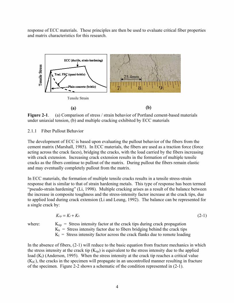
2.0 Introduction Engineered cementitious composite materials (ECC), which exhibit a pseudo-strain hardening response in tension, represent an innovative composite material. The material is comprised of a Portland cement paste or mortar matrix with a low volume fraction of fibers such as ultra high molecular weight polyethylene (UHMWPE) or polyvinyl alcohol (PVA) fibers. The unique feature of the material is its ability to exhibit multiple cracking in tension, which provides significant tensile strain capacity, in contrast to the brittle behavior of traditional cementitious materials. Continued development of the materials will give engineers greater flexibility to design and rehabilitate structures to withstand seismic and other types of loading. ECC materials are part of a larger class of materials, fiber reinforced concrete (FRC). In this section, background information is presented that describes the micro-mechanical principles and analysis used in the development of ECC materials. Some of the differences between ECC and FRC materials will also be highlighted. A review of applications of ECC materials will also be presented. 2.1 ECC Material Behavior Traditional unreinforced, cementitious materials do not possess significant tensile strain capacity (typically less than 0.015% strain) or tensile strength (typically less than 3.5 MPa). The behavior of traditional unreinforced, cementitious materials is in contrast to ECC materials, which rely upon a small volume fraction of fibers to bridge and stabilize the cracks that occur when the material is loaded in tension. The fibers in ECC give the material tensile strain capacities ranging from 0.5 to 6% and tensile strengths from 2 to 8 MPa (Li, 1998a). Figure 2-1(a) shows a comparison of the uniaxial tension behavior of ECC with plain and traditional fiber reinforced concrete. Figure 2-1(b) shows an example of the multiple cracks which give rise to the pseudo-strain hardening behavior of ECC materials. The majority of research into the development of ECC materials has been performed at the University of Michigan under the direction of Prof. Victor Li. The approach used to develop the material is based upon tailoring the micro-mechanical properties of the material to produce steady-state cracking when the material is loaded in tension. Steady-state cracking refers to cracks propagating in the material without an increase in applied load. This results in pseudo-strain hardening behavior when multiple cracks are able to form in the material as seen in figure 2-1. (Li, 1998a) The pseudo-strain hardening in the materials refers to the increase in stress in the materials with increasing strain after the initial crack formation. The pseudo-strain hardening is similar in nature to plastic deformations observed in metals, however both arise from different mechanisms. The ductile, strain-hardening response of ECC materials to tensile loadings is a direct consequence of the pullout of fibers from the cement matrix. In the following sections the pullout behavior of the fibers is reviewed to highlight the micromechanical basis for the tensile
4
response of ECC materials. These principles are then be used to evaluate critical fiber properties and matrix characteristics for this research.
Figure 2-1. (a) Comparison of stress / strain behavior of Portland cement-based materials under uniaxial tension, (b) and multiple cracking exhibited by ECC materials 2.1.1 Fiber Pullout Behavior The development of ECC is based upon evaluating the pullout behavior of the fibers from the cement matrix (Marshall, 1985). In ECC materials, the fibers are used as a traction force (force acting across the crack faces), bridging the cracks, with the load carried by the fibers increasing with crack extension. Increasing crack extension results in the formation of multiple tensile cracks as the fibers continue to pullout of the matrix. During pullout the fibers remain elastic and may eventually completely pullout from the matrix. In ECC materials, the formation of multiple tensile cracks results in a tensile stress-strain response that is similar to that of strain hardening metals. This type of response has been termed “pseudo-strain hardening” (Li, 1998). Multiple cracking arises as a result of the balance between the increase in composite toughness and the stress-intensity factor increase at the crack tips, due to applied load during crack extension (Li and Leung, 1992). The balance can be represented for a single crack by:
tip l bK K K= + (2-1)
where: Ktip = Stress intensity factor at the crack tips during crack propagation Kb = Stress intensity factor due to fibers bridging behind the crack tips Kl = Stress intensity factor across the crack flanks due to remote loading
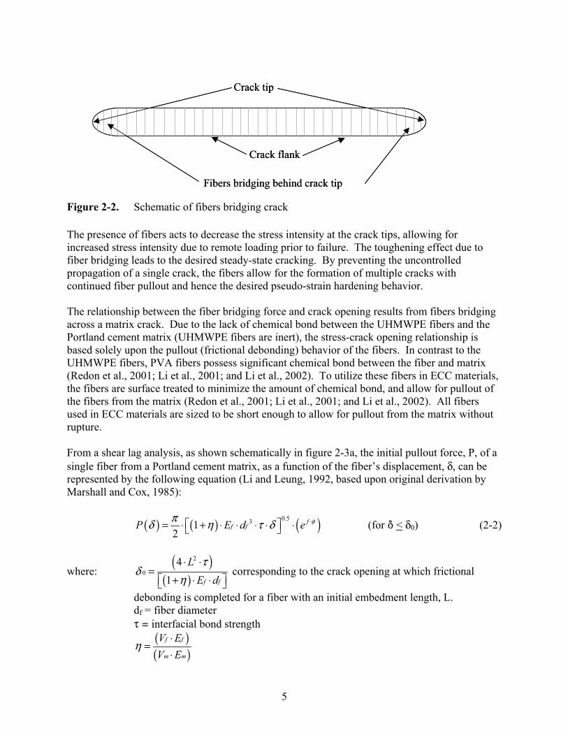
In the absence of fibers, (2-1) will reduce to the basic equation from fracture mechanics in which the stress intensity at the crack tip (Ktip) is equivalent to the stress intensity due to the applied load (Kl) (Anderson, 1995). When the stress intensity at the crack tip reaches a critical value (KIC), the cracks in the specimen will propagate in an uncontrolled manner resulting in fracture of the specimen. Figure 2-2 shows a schematic of the condition represented in (2-1).
Trad. FRC (quasi-brittle)
ECC (ductile, strain-hardening)
Tens
ile S
tress
Tensile Strain
Plain concrete (brittle)
(a) (b)
25.4mmTrad. FRC (quasi-brittle)
ECC (ductile, strain-hardening)
Tens
ile S
tress
Tensile Strain
Plain concrete (brittle)
(a)
Trad. FRC (quasi-brittle)
ECC (ductile, strain-hardening)
Tens
ile S
tress
Tensile Strain
Plain concrete (brittle)
Trad. FRC (quasi-brittle)
ECC (ductile, strain-hardening)
Tens
ile S
tress
Tensile Strain
Plain concrete (brittle)
(a) (b)
25.4mm
(b)
25.4mm
5
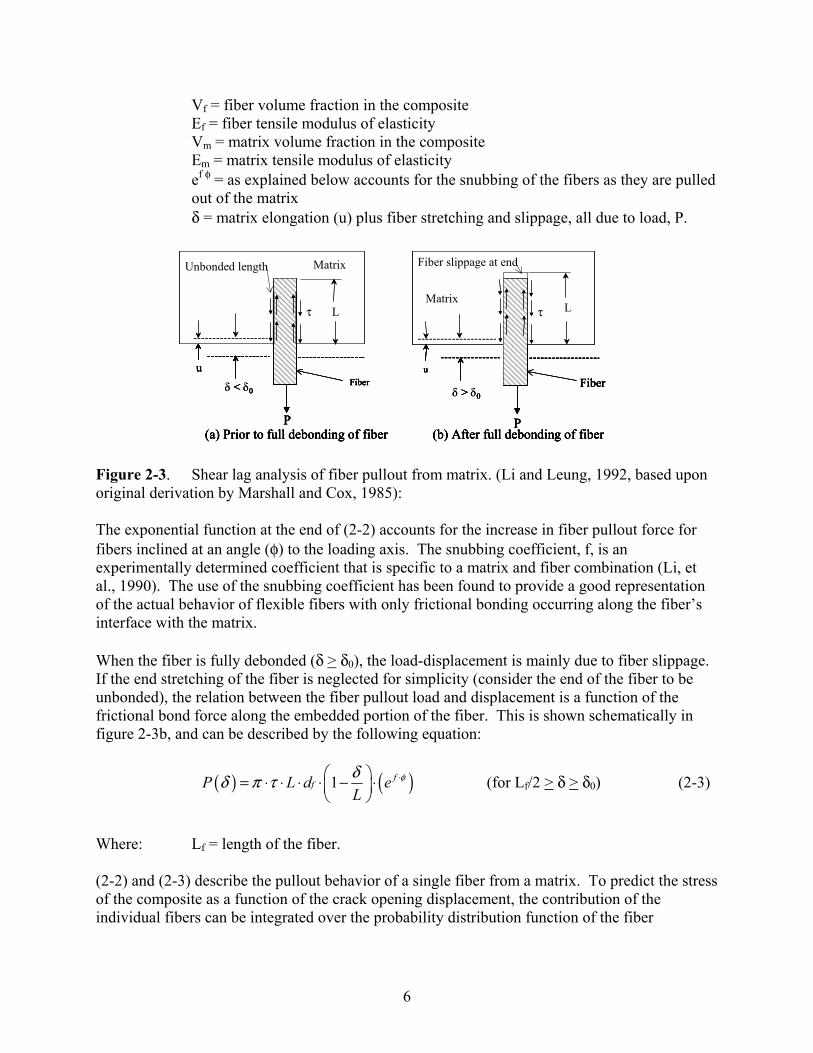
Figure 2-2. Schematic of fibers bridging crack The presence of fibers acts to decrease the stress intensity at the crack tips, allowing for increased stress intensity due to remote loading prior to failure. The toughening effect due to fiber bridging leads to the desired steady-state cracking. By preventing the uncontrolled propagation of a single crack, the fibers allow for the formation of multiple cracks with continued fiber pullout and hence the desired pseudo-strain hardening behavior. The relationship between the fiber bridging force and crack opening results from fibers bridging across a matrix crack. Due to the lack of chemical bond between the UHMWPE fibers and the Portland cement matrix (UHMWPE fibers are inert), the stress-crack opening relationship is based solely upon the pullout (frictional debonding) behavior of the fibers. In contrast to the UHMWPE fibers, PVA fibers possess significant chemical bond between the fiber and matrix (Redon et al., 2001; Li et al., 2001; and Li et al., 2002). To utilize these fibers in ECC materials, the fibers are surface treated to minimize the amount of chemical bond, and allow for pullout of the fibers from the matrix (Redon et al., 2001; Li et al., 2001; and Li et al., 2002). All fibers used in ECC materials are sized to be short enough to allow for pullout from the matrix without rupture. From a shear lag analysis, as shown schematically in figure 2-3a, the initial pullout force, P, of a single fiber from a Portland cement matrix, as a function of the fiber’s displacement, δ, can be represented by the following equation (Li and Leung, 1992, based upon original derivation by Marshall and Cox, 1985):
( ) ( ) ( )0.5312
ff fP E d e φπδ η τ δ ⋅⎡ ⎤= ⋅ + ⋅ ⋅ ⋅ ⋅ ⋅⎣ ⎦ (for * < δ0) (2-2)
where: ( )
( )
2
04
1 f f
LE dτ
δη⋅ ⋅
=+ ⋅ ⋅⎡ ⎤⎣ ⎦
corresponding to the crack opening at which frictional
debonding is completed for a fiber with an initial embedment length, L. df = fiber diameter τ = interfacial bond strength
( )( )
f f
m m
V EV E
η⋅
=⋅
Crack flank
Fibers bridging behind crack tip
Crack tip
Crack flank
Fibers bridging behind crack tip
Crack tip
6
Vf = fiber volume fraction in the composite Ef = fiber tensile modulus of elasticity Vm = matrix volume fraction in the composite Em = matrix tensile modulus of elasticity
ef φ = as explained below accounts for the snubbing of the fibers as they are pulled out of the matrix δ = matrix elongation (u) plus fiber stretching and slippage, all due to load, P.
Figure 2-3. Shear lag analysis of fiber pullout from matrix. (Li and Leung, 1992, based upon original derivation by Marshall and Cox, 1985): The exponential function at the end of (2-2) accounts for the increase in fiber pullout force for fibers inclined at an angle (φ) to the loading axis. The snubbing coefficient, f, is an experimentally determined coefficient that is specific to a matrix and fiber combination (Li, et al., 1990). The use of the snubbing coefficient has been found to provide a good representation of the actual behavior of flexible fibers with only frictional bonding occurring along the fiber’s interface with the matrix. When the fiber is fully debonded (δ > δ0), the load-displacement is mainly due to fiber slippage. If the end stretching of the fiber is neglected for simplicity (consider the end of the fiber to be unbonded), the relation between the fiber pullout load and displacement is a function of the frictional bond force along the embedded portion of the fiber. This is shown schematically in figure 2-3b, and can be described by the following equation:
( ) ( )1 ffP L d e
Lφδδ π τ ⋅⎛ ⎞= ⋅ ⋅ ⋅ ⋅ − ⋅⎜ ⎟
⎝ ⎠ (for Lf/2 > δ > δ0) (2-3)
Where: Lf = length of the fiber. (2-2) and (2-3) describe the pullout behavior of a single fiber from a matrix. To predict the stress of the composite as a function of the crack opening displacement, the contribution of the individual fibers can be integrated over the probability distribution function of the fiber
L
δ < δ0
P
ϑ
Fiber
MatrixUnbonded length
u
L
δ > δ0
P
ϑ
Fiber
Matrix
Fiber slippage at end
u
(a) Prior to full debonding of fiber (b) After full debonding of fiber
L
< 0
P
τ
Fiber
MatrixUnbonded length
u
L
> 0
P
τ
Fiber
Matrix
Fiber slippage at end
u
(a) Prior to full debonding of fiber (b) After full debonding of fiber
L
δ < δ0
P
ϑ
Fiber
MatrixUnbonded length
u
L
δ > δ0
P
ϑ
Fiber
Matrix
Fiber slippage at end
u
(a) Prior to full debonding of fiber (b) After full debonding of fiber
L
< 0
P
τ
Fiber
MatrixUnbonded length
u
L
> 0
P
τ
Fiber
Matrix
Fiber slippage at end
u
(a) Prior to full debonding of fiber (b) After full debonding of fiber

7
orientation angle (φ) and the centroidal distance of the fibers from the crack plane as shown below (Li et al., 1990):
( ) ( ) ( ) ( )2
4 fb
f
V P p p z zd
σ δ δ φ φπ
⋅⎛ ⎞= ⋅ ⋅ ⋅ ⋅∂ ⋅∂⎜ ⎟⋅⎝ ⎠ ∫∫ (2-4)
where: p(φ) and p(z) represent the probability distribution function of the orientation
angle and the centroidal distance of fibers from the crack plane, respectively. For a uniform, three dimensional, random fiber distribution, p(φ) = sin (φ) evaluated from 0 to π/2 and p(z) = 2 / Lf, evaluated from 0 to ((Lf / 2) cos (φ)) (Li, et al., 1990) P(δ) = the result obtained from (2-2) or (2-3) depending upon the displacement range being considered
(2-2) to (2-4) can be used to evaluate the load or stress versus displacement relationship for a fiber reinforced cementitious composite material. (2-4) will equal the remote applied stress in a uniaxial tension test. The maximum value of (2-4) is referred to as the maximum bridging stress. The maximum bridging stress represents an upper limit on the stress that can be transferred by fibers across an individual crack. This can be represented as (Li and Leung, 1992):
2f
brf
L
dg Vfτσ ⋅ ⋅ ⎛ ⎞= ⋅⎜ ⎟
⎝ ⎠ (2-5)
where: brσ = maximum bridging stress (Li and Leung, 1992) g = snubbing factor which is related to the snubbing coefficient, f As seen in (2-5), the maximum bridging stress is solely a function of fiber and interface properties, and the snubbing factor, g, which accounts for the effects of inclined pullout of the fibers from the matrix. Matrix properties only influence the snubbing factor as the fibers pull out of the matrix and do not have a direct influence on the maximum bridging stress. The maximum bridging stress acts as an upper limit on the stress carried during pseudo-strain hardening.
2.1.2 Steady-State Cracking Steady-state cracking is essential for ductility in ECC. Steady-state cracking occurs under two conditions: (1) the stress at the midpoint of the crack must equal the first crack strength; and (2) the crack-opening displacement at the midpoint of the crack must be less than the displacement corresponding to the maximum bridging stress (Li and Leung, 1992). These two conditions place limits on the stress and opening size of cracks. When the first requirement is satisfied, the continued pullout of fibers will result in the formation of new cracks without an increase in applied load. When the second requirement is satisfied, the crack will have a parabolic shape with the cracks tips flattened out (Marshall and Cox, 1987). The flattened shape of the crack tips (crack flanks) allows the fibers behind the crack tip to be effective in limiting the stress intensity at the crack tips. If condition 2 is not satisfied, the crack will have sufficient opening width to
8
prevent the fibers across the crack faces from being effective in bridging the cracks. This will prevent (2-1) from being satisfied, resulting in uncontrolled propagation of the cracks and a failure of the material. Using a fracture mechanics based derivation and assuming the cracks are pulled out without rupture, and assuming a penny-shaped crack with fibers bridging across the crack surfaces, the two conditions required for steady-state cracking can be satisfied in terms of a minimum required fiber volume fraction. The following equation is the result of the derivation (Li and Leung, 1992):
2
48 tipf crit
ff
f
GVLg dd
τ δ⋅ ⋅
⋅=⎛ ⎞ ∗⋅ ⋅ ⎜ ⎟⎝ ⎠
(2-6)
Where: Gtip = energy release rate at the crack tip g = snubbing factor related to the snubbing coefficient, f δ* = the maximum attainable value of δ0 (corresponding to an embedment length of Lf / 2) δ0 = the crack opening at which frictional debonding is completed for a fiber with embedment length, L τ = interfacial bond strength between fiber and matrix df = fiber diameter Lf = fiber length
For typical fibers used in ECC, the critical fiber fractions have been found to range from 0.5% to 4% (Li and Leung, 1992). (2-6) suggests that as the fracture energy (as measured by the energy release rate at the crack tip, Gtip) of the matrix increases, the fiber-volume fraction, Vf, must increase to maintain steady-state cracking. Examination of (2-6) also indicates that optimizing the following fiber properties is critical in the development of ductile cementitious materials:
• Elastic tensile modulus (Ef) (due to δ*) • Aspect ratio (Lf/df) • Interfacial bond strength (τ)
Table 2-1 shows representative values of these properties for fibers that have been used in ECC materials.
9
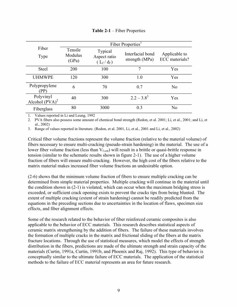
Table 2-1 – Fiber Properties
Fiber Properties1
Fiber
Type Tensile
Modulus (GPa)
Typical Aspect ratio
( Lf / df )
Interfacial bond strength (MPa)
Applicable to ECC materials?
Steel 200 100 7 Yes
UHMWPE 120 300 1.0 Yes
Polypropylene (PP)
6 70 0.7 No
Polyvinyl Alcohol (PVA)2
40 300 2.2 – 3.83 Yes
Fiberglass 80 3000 0.3 No 1. Values reported in Li and Leung, 1992 2. PVA fibers also possess some amount of chemical bond strength (Redon, et al. 2001; Li, et al., 2001; and Li, et
al., 2002) 3. Range of values reported in literature. (Redon, et al. 2001, Li, et al., 2001 and Li, et al., 2002) Critical fiber volume fractions represent the volume fraction (relative to the material volume) of fibers necessary to ensure multi-cracking (pseudo-strain hardening) in the material. The use of a lower fiber volume fraction (less than Vf crit) will result in a brittle or quasi-brittle response in tension (similar to the schematic results shown in figure 2-1). The use of a higher volume fraction of fibers will ensure multi-cracking. However, the high cost of the fibers relative to the matrix material makes increased fiber volume fractions an undesirable option. (2-6) shows that the minimum volume fraction of fibers to ensure multiple cracking can be determined from simple material properties. Multiple cracking will continue in the material until the condition shown in (2-1) is violated, which can occur when the maximum bridging stress is exceeded, or sufficient crack opening exists to prevent the cracks tips from being blunted. The extent of multiple cracking (extent of strain hardening) cannot be readily predicted from the equations in the preceding sections due to uncertainties in the location of flaws, specimen size effects, and fiber alignment effects. Some of the research related to the behavior of fiber reinforced ceramic composites is also applicable to the behavior of ECC materials. This research describes statistical aspects of ceramic matrix strengthening by the addition of fibers. The failure of these materials involves the formation of multiple cracks in the matrix and frictional sliding of the fibers at the matrix fracture locations. Through the use of statistical measures, which model the effects of strength distribution in the fibers, predictions are made of the ultimate strength and strain capacity of the materials (Curtin, 1991a, Curtin, 1991b, and Phoenix and Raj, 1992). This type of behavior is conceptually similar to the ultimate failure of ECC materials. The application of the statistical methods to the failure of ECC material represents an area for future research.
10
2.1.3 Compressive Response of ECC Materials The compressive response of ECC materials is expected to be similar to the response of mortar. The lack of aggregate in the ECC materials is expected to result in a lower modulus of elasticity compared to traditional concrete materials. The lower modulus of elasticity will occur because typical aggregate materials have a higher modulus of elasticity than a Portland cement matrix (Mehta, 1986). Li (1998a) examined the compressive behavior of ECC materials and found the peak compressive strength is similar to traditional concretes and FRCs, with a lower modulus of elasticity. The lower modulus of elasticity results in a higher strain at the peak compressive strength when compared to more traditional cementitious materials. 2.1.4 Cyclic Response of ECC Materials The response of ECC to cyclic loadings with both tensile and compressive cycles has not been extensively examined in previous research. Fukuyama, et al. (1999) studied the cyclic response of a PVA fiber ECC material. In the testing, the specimens were initially loaded in tension, to a point beyond the peak tensile stress. After unloading, the specimens were loaded in compression to failure. This testing allowed for the shape of the tensile-compressive strength envelope to be determined. The effect of cyclic unloading and reloading in tension or compression was not examined. Fukuyama, et al. addressed the effect of cyclic unloading and reloading in a later paper (2002).
2.1.5 Use of Aggregates in ECC Materials Li, et al. (1995) examined the use of aggregates in the matrix of ECC materials. The primary goal of the investigation was to determine the proportion of aggregates that can be used while maintaining ECC’s desirable tensile properties. The testing was conducted using various combinations of quartz sand with a fine gradation (maximum particle size of 0.3mm). This aggregate size was chosen to insure the viability of the compact tension specimens as a measure of fracture toughness. A fiber content of 2% by volume of UHMWPE fibers was used in all of the samples. Testing included measurement of the fracture toughness, tensile strength, compressive strength, and compressive modulus. Testing results were used to calculate the interfacial bond strength for the fibers from the maximum bridging stress (2-5). Interfacial bond strength was not directly measured in the program. The fracture toughness was measured using the geometry of a standard compact-tension specimen. The effect of the aggregate additions on tensile test results varied significantly depending upon the amount of aggregate used. Without aggregate, a tensile strain capacity of over 5% prior to the onset of softening was obtained. The tensile strain capacity of the material with aggregates decreased in proportion to the amount of aggregate added. In specimens with a cement-to-aggregate ratio of 2 (proportions by dry weight) the tensile strain capacity was reduced to 0.2%. The decrease in strain capacity is caused by the increase in matrix fracture toughness when aggregates are added, which force cracks to propagate a longer distance. The first crack tensile
11
strength of the materials decreased in proportion to the amount of additional aggregate used in the material. The elastic modulus of the ECC with aggregate additions, as expected, increased in proportion to the amount of aggregate added. An addition of 50% sand by weight of cement increased the elastic modulus by 28%. Further additions in the sand proportion resulted in smaller increases in elastic modulus. The compressive strength of the ECC did not correlate with the extent of aggregate additions. The highest compressive strength was found in specimens with a cement-to-aggregate ratio of 2. However, the compressive strength of ECC with a cement-to-aggregate ratio of 0.5 was lower than that of ECC made without aggregate. The reason for this variation was not apparent (Li, et al., 1995). The matrix fracture toughness of the material increased in proportion to the amount of aggregate added to the material. The matrix fracture toughness of ECC with a cement-to-aggregate ratio of 2 approximately doubled compared to the material without aggregate (Li, et al., 1995). The increase in matrix fracture toughness requires an increase in the volume fraction of fibers to ensure steady state cracking (Li and Leung, 1992). 2.1.6 Fiber Treatments Several researchers have studied the use plasma treatment of UHMWPE fibers (Li, et al., 1996, and Li and Netravali, 1992). The goal of the plasma treatment is to enhance the interfacial bond strength of the fibers from the matrix. In the research by Li, et al. (1996) the treated fibers were used in an ECC material. Li and Netravali (1992) examined the pullout of treated fibers from an epoxy matrix. Results from both researchers showed an increase in single fiber pullout strength when compared to pullout loads from untreated fibers. A higher bond strength will increase the strength of ECC compared to ECC made with untreated fibers. Surface treatments are being investigated for use on PVA fibers to limit the chemical bonding of the fibers to the matrix. Research by Redon, et al. (2001), focused on evaluation of the pullout behavior of single fibers that have been treated with oil to limit the chemical bond of the fibers to the matrix. The treated PVA fibers pulled out of the matrix without rupture of the fibers. Li, et al. (2001 and 2002) examined the uniaxial tensile response of ECC made with oiled PVA fibers. The amount of oil on the fibers was varied to determine the optimal amount of oil needed to increase the strain capacity of the materials. The investigation also examined the effect of the surface fiber treatment on the aggregate additions. The results indicated that with higher oil contents on the fibers, larger amounts of aggregates can be used in the ECC material. The higher oil contents probably protect the fibers from being damaged by the aggregates during fiber pullout, and act to decrease the resulting matrix fracture toughness.
2.2 Comparison of ECC to Other Ductile Cementitious Composite Materials ECC materials are part of a larger class of fiber reinforced concrete (FRC) materials. The primary difference between ECC materials and FRC materials is the ductile response of ECC in tension. However, some other materials will exhibit a ductile response in tension. Such as those studied by Majumdar (1970); Aveston et al. (1971); Kelly (1972); Hannant (1978); and Rossi,
12
(1997) as well as slurry-infiltrated fiber-reinforced concrete (SIFCON) (see for example Balaguru and Shah, 1992). The material examined by Majumdar (1970) used a gypsum plaster matrix instead of a Portland cement. In this section the properties of three of these materials not related to ECC are compared with the ECC materials. An overview of FRC materials is presented in Balaguru and Shah. (1992) 2.2.1 SIFCON/SIMCON SIFCON (slurry infiltrated fiber concrete) is a fiber-reinforced material that is comprised of steel fibers that are pre-placed in a form with a Portland cement-based slurry later placed to fill the spaces between the fibers (Balaguru and Shah, 1992). SIMCON (slurry infiltrated mat concrete) is similar. However in SIMCON, the individual steel fibers are replaced with an interwoven mat made of individual steel fibers (Krstulovic-Opara and Malak, 1997). Typically the slurry is Portland cement with a supplemental cementitious material such as fly ash or silica fume, water and a superplastizer. The water-to-cementitious materials ratio in the material is typically less than 0.30, which necessitates the use of the superplastizer to ensure filling spaces between the fibers (Balaguru and Shah, 1992). Both SIFCON and SIMCON have fiber volume fractions between 8 and 20 percent, depending upon the fiber geometry, orientation and size. (Balaguru and Shah, 1992; Krstulovic-Opara and Malak, 1997) The unique feature of the SIFCON/SIMCON materials is the high toughness (area under compressive stress-strain curve), and strain capacity of the material in compression. In tension, the material will exhibit a strain hardening response, with peak strengths ranging from 2.5 to over 15 MPa and tensile strain capacities ranging from 0.5 to 2% depending upon the orientation and amount of fibers used in the material. The response in tension is a consequence of fiber pullout from the matrix. Tensile failure occurs when the matrix begins to spall, allowing the cracks to localize (Balaguru and Shah, 1992). Rupture of fibers has been reported in tension testing of SIMCON materials (Krstulovic-Opara and Malak, 1997). The combination of high tensile strength and strain capacity make the materials advantageous in energy dissipation applications. In compression, both SIFCON and SIMCON exhibit a significant amount of ductility after the peak compressive strength is reached. The shape of the stress-strain curve will vary depending upon the type and fiber volume fraction (Homrich and Naaman, 1987). Applications are being developed that utilize the energy dissipation capacity of both SIFCON and SIMCON (Summary of SIFCON in Balaguru and Shah, 1992; SIMCON applications are summarized in Krstulovic-Opara and Malak, 1997). SIMCON SIFCON has also been investigated for use in precast joint regions for seismic resistance (Soubra, et al. 1991). 2.2.2 HPMFRCC High performance multimodal fiber reinforced cement composites (HPMFRCC) represent another type of highly ductile fiber reinforced cementitious composite (Rossi, 1997). The materials are comprised of Portland cement, silica fume, fine sand aggregate (diameter 400 :m), superplastizer, steel fibers and water. A very low water-to-cementitious material (<0.20) ratio is
13
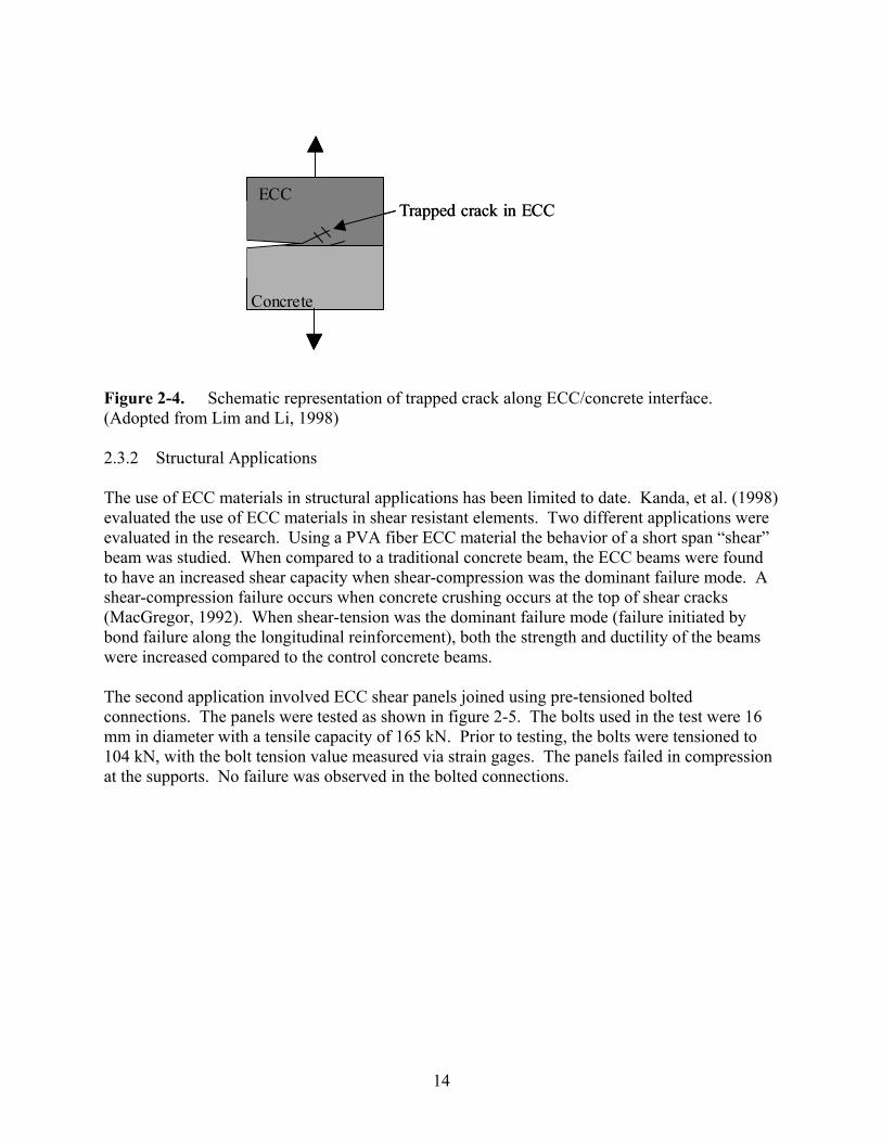
used in the materials. Two different sizes of steel fibers are used, which is referred to as “multimodal” in the name of the material. Small diameter steel fibers are used at the “material” level to improve the strength and ductility of the material. Larger fibers are used at the “structural” level to improve the load bearing capacity of the material (Rossi, 1997). The uniaxial tensile response of the material gives a strain hardening behavior with a peak tensile strength of 15 MPa. Strain capacities of the materials were not reported. Flexural tests, similar to the uniaxial tensile tests, indicated that the materials will have a deflection hardening response (Rossi, 1997). Applications for these materials currently are being developed. The applications will likely take the form of precast assemblies due to the high level of quality control needed to make the materials (Rossi, 1997). 2.3 ECC Applications The development of ECC applications can be split into two broad areas; protective applications and structural applications. Both categories of applications utilize the large tensile strain capacity of the ECC materials. In the following sections a brief review of ECC in protective and structural applications is presented, with more extensive reviews presented for applications related to the ongoing research. An overview of the ongoing development of ECC applications was presented at the JCI (Japan Concrete Institute) Workshop on Ductile Fiber Reinforced Cementitious Composites (DFRCC) in Takayama, Japan in October 2002 (JCI, 2002). 2.3.1 Protective Applications The multi-cracking of ECC materials in tension has led to several researchers evaluating their potential use in protective repairs of concrete structures. Maleej and Li (1995) evaluated the use of ECC materials as a protective, corrosion resistant layer in reinforced concrete structures. The research involved a laboratory study in which the bottom portion of reinforced concrete beams was replaced with ECC. When the beams were tested in four-point bending, smaller tensile crack widths were found in the ECC beams compared to control beams made with concrete. It was suggested that the smaller crack widths would reduce the potential for reinforcing steel corrosion. The research did not include direct corrosion testing. Lim and Li (1998) evaluated the use of ECC materials for the repair of reinforced concrete beams, with a focus on the repair of corrosion induced delaminations. The research focused on characterizing the interface fracture between ECC materials and a concrete substrate. The interface fracture toughness was measured in reduced section beam specimens made with an ECC material on one side, and concrete on the other. Lim and Li’s research introduced the concept of a crack trapping mechanism, shown schematically in figure 2-4. This mechanism allows for cracks at an interface between ECC and a concrete substrate to become trapped in ECC material away from the interface. Crack trapping prevents propagation of delaminations at the interface between materials. ECC materials, installed as a concrete overlay, were shown to trap interface cracks effectively.
14
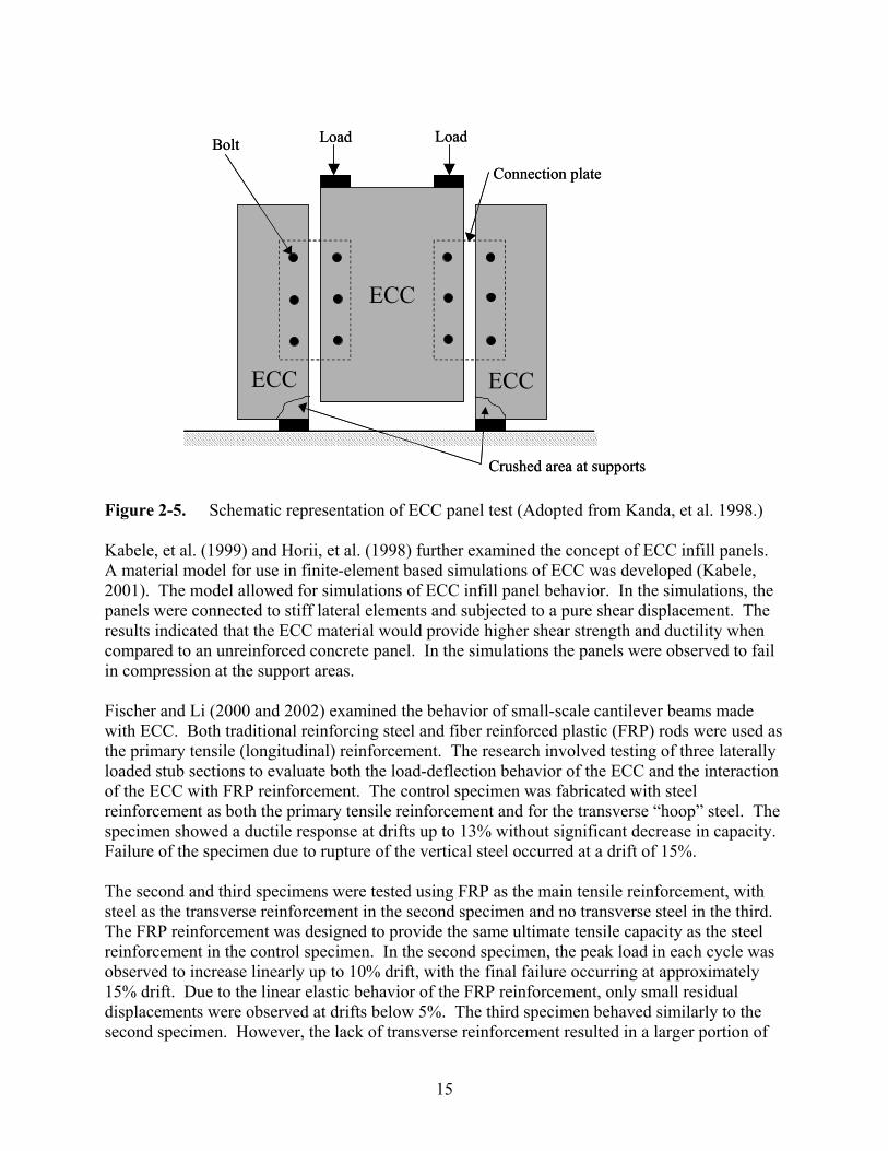
Figure 2-4. Schematic representation of trapped crack along ECC/concrete interface. (Adopted from Lim and Li, 1998) 2.3.2 Structural Applications The use of ECC materials in structural applications has been limited to date. Kanda, et al. (1998) evaluated the use of ECC materials in shear resistant elements. Two different applications were evaluated in the research. Using a PVA fiber ECC material the behavior of a short span “shear” beam was studied. When compared to a traditional concrete beam, the ECC beams were found to have an increased shear capacity when shear-compression was the dominant failure mode. A shear-compression failure occurs when concrete crushing occurs at the top of shear cracks (MacGregor, 1992). When shear-tension was the dominant failure mode (failure initiated by bond failure along the longitudinal reinforcement), both the strength and ductility of the beams were increased compared to the control concrete beams. The second application involved ECC shear panels joined using pre-tensioned bolted connections. The panels were tested as shown in figure 2-5. The bolts used in the test were 16 mm in diameter with a tensile capacity of 165 kN. Prior to testing, the bolts were tensioned to 104 kN, with the bolt tension value measured via strain gages. The panels failed in compression at the supports. No failure was observed in the bolted connections.
ECC
Concrete
Trapped crack in ECCECC
Concrete
Trapped crack in ECC
15
Figure 2-5. Schematic representation of ECC panel test (Adopted from Kanda, et al. 1998.) Kabele, et al. (1999) and Horii, et al. (1998) further examined the concept of ECC infill panels. A material model for use in finite-element based simulations of ECC was developed (Kabele, 2001). The model allowed for simulations of ECC infill panel behavior. In the simulations, the panels were connected to stiff lateral elements and subjected to a pure shear displacement. The results indicated that the ECC material would provide higher shear strength and ductility when compared to an unreinforced concrete panel. In the simulations the panels were observed to fail in compression at the support areas. Fischer and Li (2000 and 2002) examined the behavior of small-scale cantilever beams made with ECC. Both traditional reinforcing steel and fiber reinforced plastic (FRP) rods were used as the primary tensile (longitudinal) reinforcement. The research involved testing of three laterally loaded stub sections to evaluate both the load-deflection behavior of the ECC and the interaction of the ECC with FRP reinforcement. The control specimen was fabricated with steel reinforcement as both the primary tensile reinforcement and for the transverse “hoop” steel. The specimen showed a ductile response at drifts up to 13% without significant decrease in capacity. Failure of the specimen due to rupture of the vertical steel occurred at a drift of 15%. The second and third specimens were tested using FRP as the main tensile reinforcement, with steel as the transverse reinforcement in the second specimen and no transverse steel in the third. The FRP reinforcement was designed to provide the same ultimate tensile capacity as the steel reinforcement in the control specimen. In the second specimen, the peak load in each cycle was observed to increase linearly up to 10% drift, with the final failure occurring at approximately 15% drift. Due to the linear elastic behavior of the FRP reinforcement, only small residual displacements were observed at drifts below 5%. The third specimen behaved similarly to the second specimen. However, the lack of transverse reinforcement resulted in a larger portion of
ECC
Crushed area at supports
Connection plate
Load LoadBolt
ECCECC
ECC
Crushed area at supports
Connection plate
Load LoadBolt
ECCECC
16
the shear being carried in the FRP bars. This was observed to limit the maximum drift to 12%. The large drift limits reached in these experiments demonstrate the ability of the ECC materials to maintain integrity under severe loadings. Parra-Montesinos and Wight (2000) furthered examined the use of ECC in lieu of traditional concrete and transverse steel. The investigation focused on the evaluation of the seismic response of steel composite reinforced concrete (RSC) beam-column joints. In typical RSC joints, stirrups are used to provide for confinement of the concrete in the joint region and to increase the shear strength of the steel beam webs in the joint region. In one specimen ECC was used without stirrups. Elimination of the stirrups simplified construction and reduced the cost of the connection. Test results showed that the ECC specimens had a 50% increase in strength and higher energy dissipation compared to the control specimen made with concrete and steel stirrups. The ECC specimen was observed to have a higher amount of joint shear deformation compared to the other specimens. However, the higher deformation did not result in excessive damage in the connection region, and spalling of the ECC material was not observed. In a later study, Fisher and Li (2002) examined the tensile response of ECC and concrete prisms containing a 25 mm diameter deformed steel reinforcing bar, which extended out of the specimens. The tensile response of a prism containing a notch at mid-height and unnotched specimens was examined. Testing was performed in a displacement controlled testing machine, which gripped the steel bar. Testing of the notched specimens indicated that prior to the formation of cracks at the notch, both the concrete and ECC specimens had similar load distributions. After the formation of cracks at the notch, the concrete material lost its ability to carry tensile stresses, leading to localized yielding of the bar at the notch location. In the ECC specimens the formation of multiple cracks in the ECC material allowed for a more even distribution of strain in the steel through the specimen. The unnotched specimens displayed similar trends to the notched specimens. In the concrete prisms, the strain in the reinforcement quickly concentrated at the location of pre-existing shrinkage cracks in the specimen. The ECC specimen was able to develop multiple parallel cracks in the specimen, which resulted in a uniform distribution of strain in the reinforcement. Strain compatibility between the ECC and steel continued to large strain levels. The continued strain compatibility between the ECC materials and steel is a major advantage of these materials as the compatibility allows for higher amounts of distributed plastic deformations in steel reinforced ECC members, which results in increased energy dissipation compared to regular reinforced concrete members. Fischer and Li (2002) developed a composite moment resisting frame with self-centering and energy dissipation capabilities. The frame uses ECC in both the columns and beam. The columns are reinforced with FRP bars with steel bars in the beam member. The basic concept of the frame is the FRP reinforced column members are able to achieve sufficient lateral deformation to allow for the formation of plastic hinges in the beam members. Thus, the column members stay undamaged, while the beam elements dissipate energy under lateral loadings. The system utilizes the ability of the ECC to distribute flexural deformations over a large portion of the member.
17
Xia and Naaman (2002) examined the behavior of infill damper elements (IDE), which act as coupling beams between steel building columns. The IDE devices act as energy dissipators and dampers under reversed cyclic loadings. The energy dissipation is by a shear friction mechanism with the IDE devices intended to fail prior to the yielding of the steel columns. The use of ECC materials in the IDE was examined and compared to a SIFCON material and a traditional fiber reinforced concrete. The results indicated that the SIFCON IDE had the highest strength and energy dissipation. Both ECC and SIFCON were recommended for construction of IDE elements. Fukuyama, et al. (2002) developed a damper system for the retrofit of reinforced concrete structures. The dampers took the form of steel reinforced wall panel sections added as a form of retrofit shear wall. Typically, the reinforcement was installed to form an X-shape in the panels. The location of the retrofit panels in the structure, and the method of attachment to the structure were not addressed in the paper. To examine the performance of the retrofits a series of laboratory tests were performed. A shear loading was applied to the panels. However, the loading mechanism was not addressed in the paper. The testing of specimens made with an ECC material showed stable hysteretic behavior to relatively large deformations when the rotational deformation of the damper was controlled. It was concluded that the ECC wall sections could act as a damper for structural control. Yoon (2002) and Rouse (2003) have investigated the use of ECC segments for energy dissipation in precast segmental bridge piers, with unbonded posttensioning. In the research the ECC segments were used to increase the energy dissipation in the systems. The results from small-scale experiments (Yoon, 2002) showed greater energy dissipation up to drift levels of 3-6%. The ECC segments, fabricated without confinement steel, maintained their integrity much better than traditional concrete. Large-scale experiments are currently being conducted (Rouse, 2003). 2.4 Summary and Discussion The micro-mechanical basis for the behavior of ECC materials was reviewed. A review of ECC applications was also given to evaluate previous application-based research. The information presented in this section provides the background for the ECC material testing presented in Section 3 as well as for investigations on an ECC retrofit applications presented in a companion report (Kesner and Billington, 2004). In examining previous research on the behavior of ECC materials, it is clear that additional research to develop ECC materials further is needed. One of the major areas for additional research is in the cyclic response of the materials. Only a small amount of information is available in this area. Needed research includes the development of a cyclic ECC material model for use in finite element based simulations of ECC applications. Another area of additional research needed is in the dimensional stability (creep and shrinkage behavior) of ECC materials. The high Portland cement content of ECC materials will likely increase the amount of both creep and shrinkage compared to traditional cementitious materials, particularly in applications that will result in sustained compressive loadings on the materials. Concurrent with the examination of creep and shrinkage behavior an examination of the effect of
18
curing time and conditions is needed. Better knowledge of the effect of curing time and conditions will facilitate optimization of the material’s behavior. The area is currently under investigation by Rouse (2003). In previous research the use of finely graded silica sands in ECC has been examined (Li, et al., 1995). Additional research is needed to examine how alternate types of aggregates can be used in ECC. Of particular interest is the use of aggregates with low fracture toughness, such as expanded shale. The use of this type of material may be able to produce an ECC with higher aggregate contents while maintaining the desired tensile properties of the material. In the current research four areas related to ECC material development are addressed and presented in the next section. The primary area was an assessment of the response of ECC materials to reversed cyclic loadings. The other areas included an assessment of the impact of different curing and drying times on the tensile response of the materials, an examination of the tensile response from different specimen geometries, and an examination different fibers and mix designs in ECC.
19
Section 3 ECC Material Testing
3.0 Introduction In this section the results of small-scale tests on ECC materials will be presented. The three primary goals of the material testing described in this section are as follows:
1. Evaluate the effect of different curing and drying periods on the performance of ECC materials. An understanding of these effects is needed to determine optimal conditions for the production of ECC structural components.
2. Evaluate the use of different fiber types and supplemental cementitious materials (silica fume/fly ash) to determine how they can be used to develop ECC materials consistent with the theoretical background presented in Section 2.
3. Evaluate the effect of different specimen geometries on the tensile response of ECC materials. This testing is needed to examine how different geometries affect the tensile strain capacity of the materials.
4. Evaluate the response of ECC materials under reversed cyclic loadings to develop an understanding of the unloading and reloading behavior of the material and to facilitate the development of constitutive models for use in finite-element based simulations.
In this section, both the methods used in developing the tests, and the test results will be presented. The presentation of the results is in four sections that correspond to the testing goals presented above. A brief summary of the salient points presented concludes this section. The information presented in this section represents a bridge between the theoretical background information presented in Section 2, and the applications investigated in a companion report (Kesner and Billington, 2004). The experience gained in the fabrication of the ECC materials used in this testing described in the section provided the groundwork for fabrication of larger ECC specimens described in Kesner and Billington (2004). 3.1 Evaluation of Different Curing and Drying Periods Traditional concrete materials are typically moist cured for a period of time to enhance desirable properties of the material such as compressive strength and resistance to drying shrinkage cracking (Mehta, 1986). The wet curing period for typical concrete structures will vary widely depending upon the type of construction and materials being placed. The variability in curing time in field applications is in contrast to standardized laboratory testing of concrete materials in compression, where a wet curing period of 28 days is used prior to testing (ASTM C-39, 2002). However, different curing periods have been suggested for laboratory testing to better represent the actual curing conditions experienced by materials in the field (Poston et al., 1998). A similar approach as taken by Poston et al. was used here to examine the impact of different wet curing and drying periods on the tensile response of ECC materials. In previous research of ECC materials, a 28-day wet curing period has been used (Li, 1998). In the previous work by Li, the specimens were reported to be stored under laboratory conditions (approximately 22 deg. C, and 50% relative humidity) after the cessation of wet curing. The exact length of the drying period prior to testing was not typically specified in the literature.
20
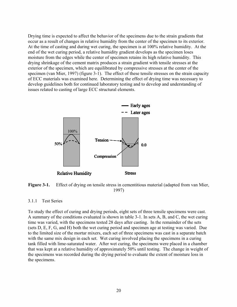
Drying time is expected to affect the behavior of the specimens due to the strain gradients that occur as a result of changes in relative humidity from the center of the specimen to its exterior. At the time of casting and during wet curing, the specimen is at 100% relative humidity. At the end of the wet curing period, a relative humidity gradient develops as the specimen loses moisture from the edges while the center of specimen retains its high relative humidity. This drying shrinkage of the cement matrix produces a strain gradient with tensile stresses at the exterior of the specimen, which are equilibrated by compressive stresses at the center of the specimen (van Mier, 1997) (figure 3-1). The effect of these tensile stresses on the strain capacity of ECC materials was examined here. Determining the effect of drying time was necessary to develop guidelines both for continued laboratory testing and to develop and understanding of issues related to casting of large ECC structural elements.
Figure 3-1. Effect of drying on tensile stress in cementitious material (adapted from van Mier,
1997) 3.1.1 Test Series To study the effect of curing and drying periods, eight sets of three tensile specimens were cast. A summary of the conditions evaluated is shown in table 3-1. In sets A, B, and C, the wet curing time was varied, with the specimens tested 28 days after casting. In the remainder of the sets (sets D, E, F, G, and H) both the wet curing period and specimen age at testing was varied. Due to the limited size of the mortar mixers, each set of three specimens was cast in a separate batch with the same mix design in each set. Wet curing involved placing the specimens in a curing tank filled with lime-saturated water. After wet curing, the specimens were placed in a chamber that was kept at a relative humidity of approximately 50% until testing. The change in weight of the specimens was recorded during the drying period to evaluate the extent of moisture loss in the specimens.
Relative Humidity
1.0
50%
Relative Humidity
100%
Stress
Early agesLater ages
Compression
Tension0.0
Stress
Early agesLater ages
Compression
Tension0.0
Relative Humidity
1.0
50%
Relative Humidity
100%
Relative Humidity
1.0
50%
Relative Humidity
100%
Stress
Early agesLater ages
Compression
Tension0.0
Stress
Early agesLater ages
Compression
Tension0.0
Stress
Early agesLater ages
Compression
Tension0.0
Stress
Early agesLater ages
Compression
Tension0.0
21
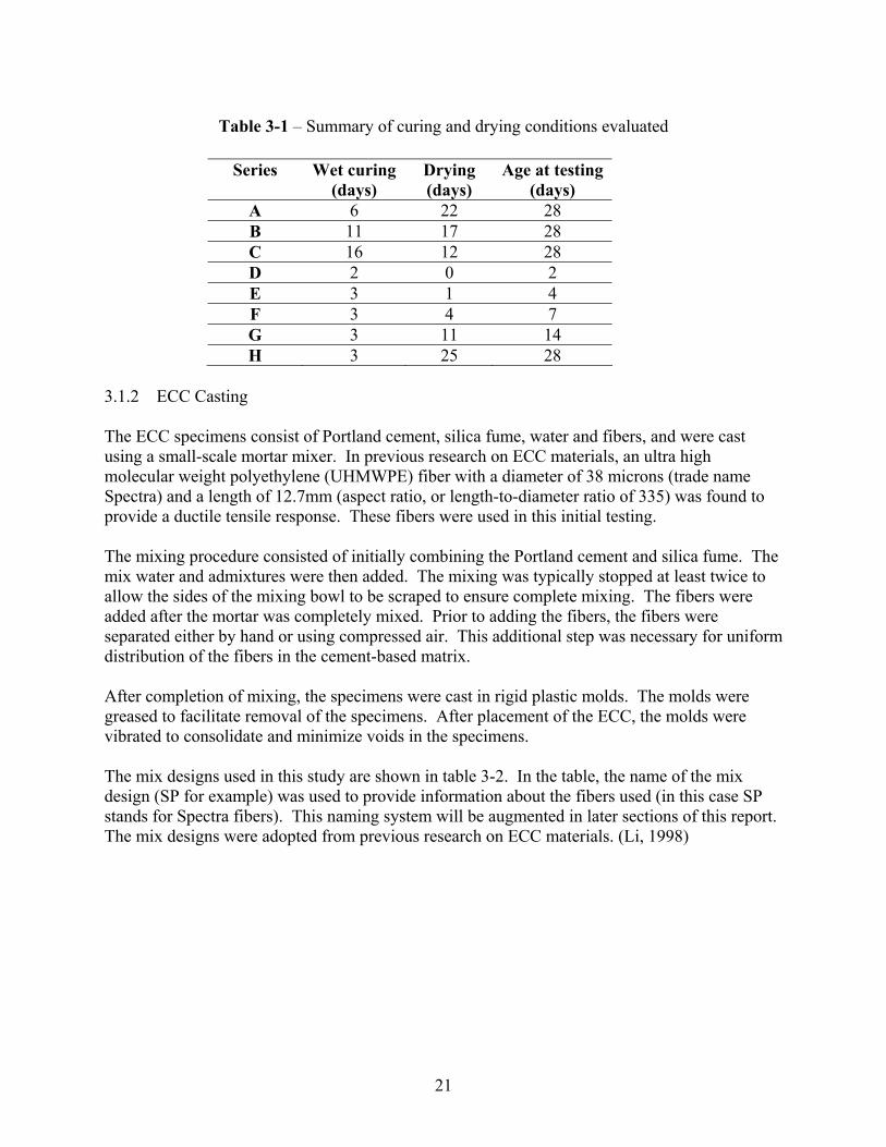
Table 3-1 – Summary of curing and drying conditions evaluated
Series Wet curing (days)
Drying (days)
Age at testing(days)
A 6 22 28 B 11 17 28 C 16 12 28 D 2 0 2 E 3 1 4 F 3 4 7 G 3 11 14 H 3 25 28
3.1.2 ECC Casting The ECC specimens consist of Portland cement, silica fume, water and fibers, and were cast using a small-scale mortar mixer. In previous research on ECC materials, an ultra high molecular weight polyethylene (UHMWPE) fiber with a diameter of 38 microns (trade name Spectra) and a length of 12.7mm (aspect ratio, or length-to-diameter ratio of 335) was found to provide a ductile tensile response. These fibers were used in this initial testing. The mixing procedure consisted of initially combining the Portland cement and silica fume. The mix water and admixtures were then added. The mixing was typically stopped at least twice to allow the sides of the mixing bowl to be scraped to ensure complete mixing. The fibers were added after the mortar was completely mixed. Prior to adding the fibers, the fibers were separated either by hand or using compressed air. This additional step was necessary for uniform distribution of the fibers in the cement-based matrix. After completion of mixing, the specimens were cast in rigid plastic molds. The molds were greased to facilitate removal of the specimens. After placement of the ECC, the molds were vibrated to consolidate and minimize voids in the specimens. The mix designs used in this study are shown in table 3-2. In the table, the name of the mix design (SP for example) was used to provide information about the fibers used (in this case SP stands for Spectra fibers). This naming system will be augmented in later sections of this report. The mix designs were adopted from previous research on ECC materials. (Li, 1998)
22
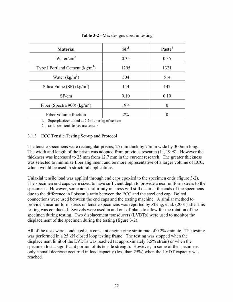
Table 3-2 –Mix designs used in testing
Material SP1 Paste1
Water/cm2 0.35 0.35
Type I Portland Cement (kg/m3) 1295 1321
Water (kg/m3) 504 514
Silica Fume (SF) (kg/m3) 144 147
SF/cm 0.10 0.10
Fiber (Spectra 900) (kg/m3) 19.4 0
Fiber volume fraction 2% 0 1. Superplastizer added at 2.2mL per kg of cement 2. cm: cementitious materials
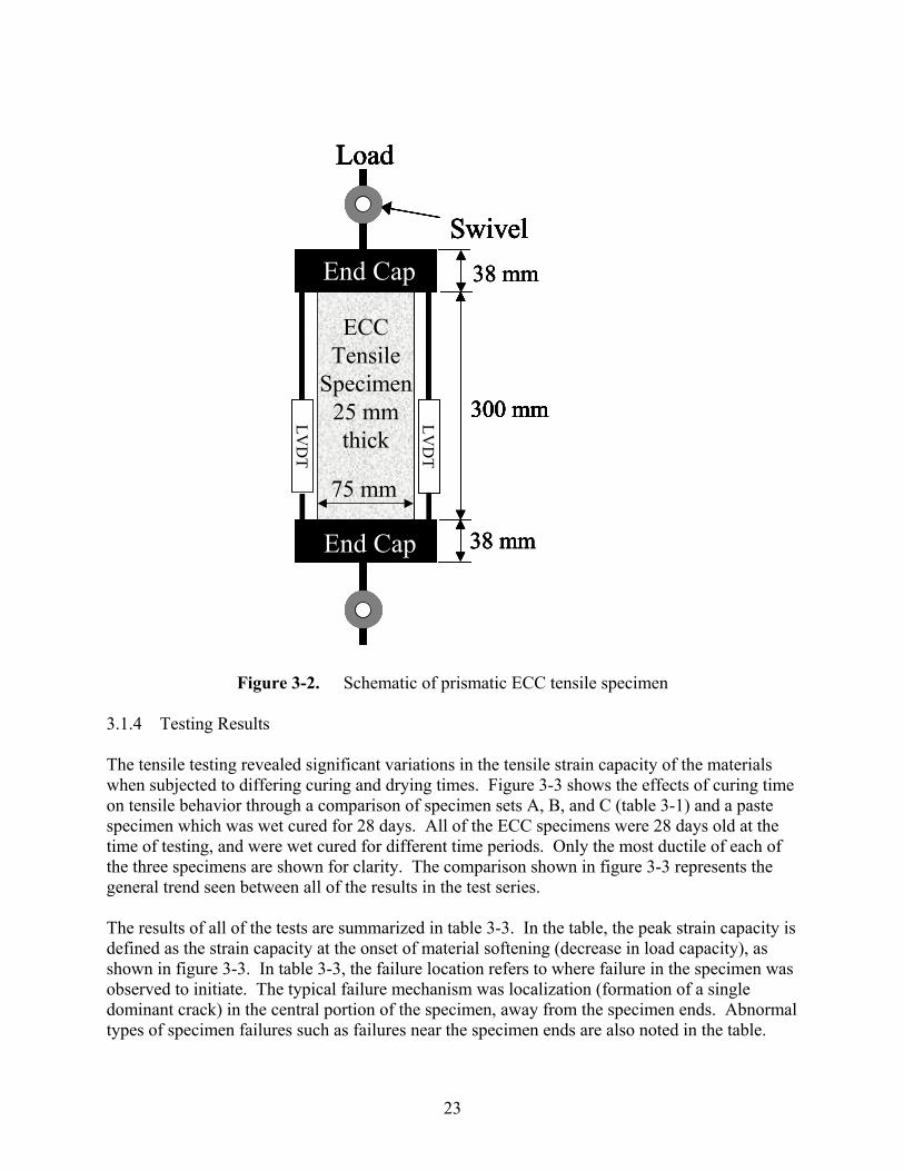
3.1.3 ECC Tensile Testing Set-up and Protocol The tensile specimens were rectangular prisms; 25 mm thick by 75mm wide by 300mm long. The width and length of the prism was adopted from previous research (Li, 1998). However the thickness was increased to 25 mm from 12.7 mm in the current research. The greater thickness was selected to minimize fiber alignment and be more representative of a larger volume of ECC, which would be used in structural applications. Uniaxial tensile load was applied through end caps epoxied to the specimen ends (figure 3-2). The specimen end caps were sized to have sufficient depth to provide a near uniform stress to the specimens. However, some non-uniformity in stress will still occur at the ends of the specimens due to the difference in Poisson’s ratio between the ECC and the steel end cap. Bolted connections were used between the end caps and the testing machine. A similar method to provide a near uniform stress on tensile specimens was reported by Zheng, et al. (2001) after this testing was conducted. Swivels were used in and out-of-plane to allow for the rotation of the specimen during testing. Two displacement transducers (LVDTs) were used to monitor the displacement of the specimen during the testing (figure 3-2). All of the tests were conducted at a constant engineering strain rate of 0.2% /minute. The testing was performed in a 25 kN closed loop testing frame. The testing was stopped when the displacement limit of the LVDTs was reached (at approximately 3.5% strain) or when the specimen lost a significant portion of its tensile strength. However, in some of the specimens only a small decrease occurred in load capacity (less than 25%) when the LVDT capacity was reached.
23
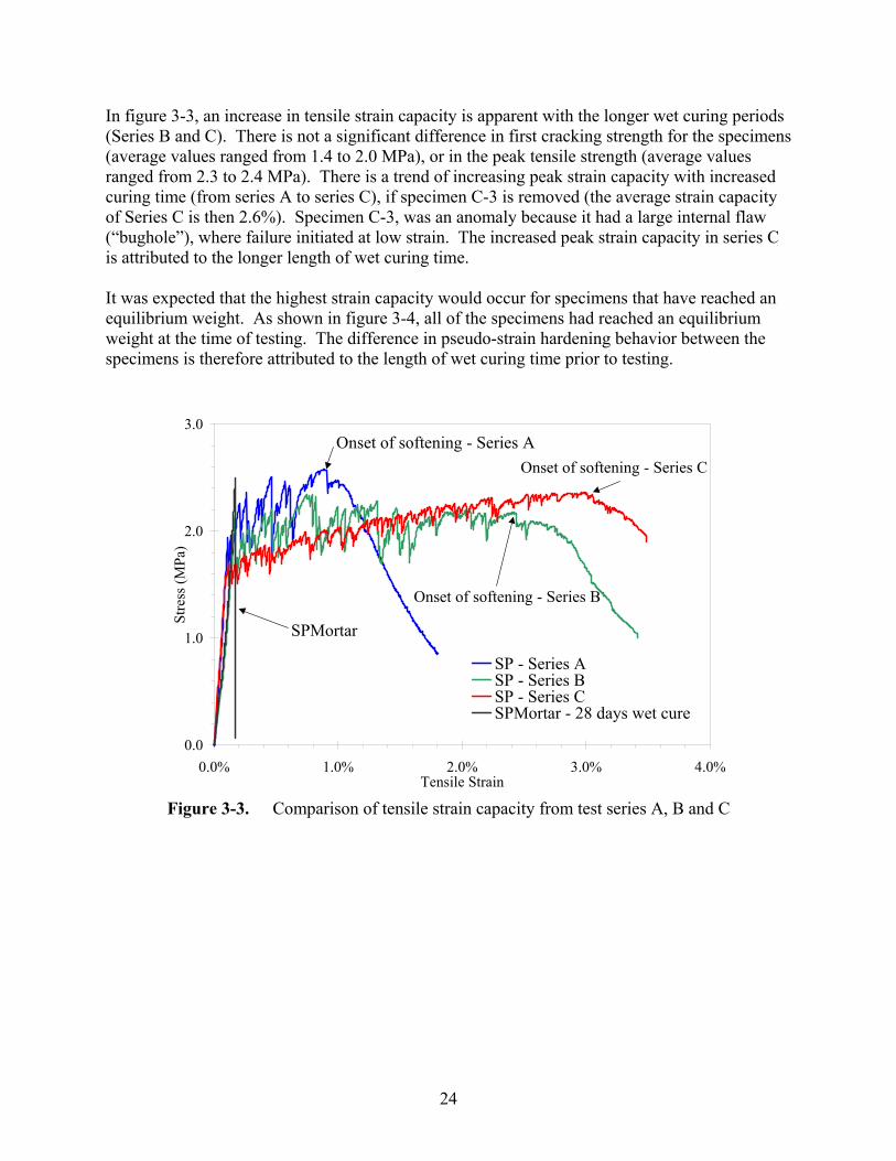
Figure 3-2. Schematic of prismatic ECC tensile specimen 3.1.4 Testing Results The tensile testing revealed significant variations in the tensile strain capacity of the materials when subjected to differing curing and drying times. Figure 3-3 shows the effects of curing time on tensile behavior through a comparison of specimen sets A, B, and C (table 3-1) and a paste specimen which was wet cured for 28 days. All of the ECC specimens were 28 days old at the time of testing, and were wet cured for different time periods. Only the most ductile of each of the three specimens are shown for clarity. The comparison shown in figure 3-3 represents the general trend seen between all of the results in the test series. The results of all of the tests are summarized in table 3-3. In the table, the peak strain capacity is defined as the strain capacity at the onset of material softening (decrease in load capacity), as shown in figure 3-3. In table 3-3, the failure location refers to where failure in the specimen was observed to initiate. The typical failure mechanism was localization (formation of a single dominant crack) in the central portion of the specimen, away from the specimen ends. Abnormal types of specimen failures such as failures near the specimen ends are also noted in the table.
Load
LVD
T
LVD
T
ECCTensile
Specimen25 mmthick
Swivel
75 mm
300 mm
38 mm
38 mm
Load
LVD
T
LVD
T
ECCTensile
Specimen25 mmthick
Swivel
75 mm
300 mm
Load
LVD
T
LVD
T
ECCTensile
Specimen25 mmthick
Swivel
75 mm
300 mm
38 mm
38 mmEnd Cap
End Cap
Load
LVD
T
LVD
T
ECCTensile
Specimen25 mmthick
Swivel
75 mm
300 mm
38 mm
38 mm
Load
LVD
T
LVD
T
ECCTensile
Specimen25 mmthick
Swivel
75 mm
300 mm
Load
LVD
T
LVD
T
ECCTensile
Specimen25 mmthick
Swivel
75 mm
300 mm
38 mm
38 mmEnd Cap
End Cap
24
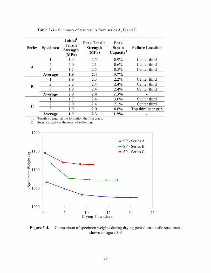
In figure 3-3, an increase in tensile strain capacity is apparent with the longer wet curing periods (Series B and C). There is not a significant difference in first cracking strength for the specimens (average values ranged from 1.4 to 2.0 MPa), or in the peak tensile strength (average values ranged from 2.3 to 2.4 MPa). There is a trend of increasing peak strain capacity with increased curing time (from series A to series C), if specimen C-3 is removed (the average strain capacity of Series C is then 2.6%). Specimen C-3, was an anomaly because it had a large internal flaw (“bughole”), where failure initiated at low strain. The increased peak strain capacity in series C is attributed to the longer length of wet curing time. It was expected that the highest strain capacity would occur for specimens that have reached an equilibrium weight. As shown in figure 3-4, all of the specimens had reached an equilibrium weight at the time of testing. The difference in pseudo-strain hardening behavior between the specimens is therefore attributed to the length of wet curing time prior to testing.
Figure 3-3. Comparison of tensile strain capacity from test series A, B and C
0.0
1.0
2.0
3.0
0.0% 1.0% 2.0% 3.0% 4.0%Tensile Strain
Stre
ss (M
Pa)
SP - Series ASP - Series BSP - Series CSPMortar - 28 days wet cure
Onset of softening - Series A
Onset of softening - Series B
Onset of softening - Series C
SPMortar
25
Table 3-3 – Summary of test results from series A, B and C
Series Specimen
Initial1 Tensile
Strength (MPa)
Peak Tensile Strength
(MPa)
Peak Strain
Capacity2 Failure Location
1 1.9 2.5 0.9% Center third 2 2.0 2.1 0.6% Center third 3 1.7 2.5 0.5% Center third A
Average 1.9 2.4 0.7% - 1 1.9 2.3 2.2% Center third 2 2.2 2.4 2.4% Center third 3 1.9 2.4 2.4% Center third B
Average 2.0 2.4 2.3% - 1 1.7 2.4 3.0% Center third 2 2.0 2.4 2.1% Center third 3 1.9 2.0 0.6% Top third near grip C
Average 1.9 2.3 1.9% - 1. Tensile strength at the formation the first crack. 2. Strain capacity at the onset of softening.
Figure 3-4. Comparison of specimen weights during drying period for tensile specimens
shown in figure 3-3
1000
1050
1100
1150
1200
0 5 10 15 20 25Drying Time (days)
Spec
imen
t Wei
ght (
g)
SP - Series ASP - Series BSP - Series C
26
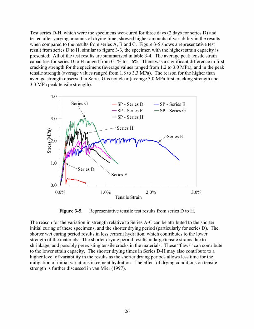
Test series D-H, which were the specimens wet-cured for three days (2 days for series D) and tested after varying amounts of drying time, showed higher amounts of variability in the results when compared to the results from series A, B and C. Figure 3-5 shows a representative test result from series D to H; similar to figure 3-3, the specimen with the highest strain capacity is presented. All of the test results are summarized in table 3-4. The average peak tensile strain capacities for series D to H ranged from 0.1% to 1.6%. There was a significant difference in first cracking strength for the specimens (average values ranged from 1.2 to 3.0 MPa), and in the peak tensile strength (average values ranged from 1.8 to 3.3 MPa). The reason for the higher than average strength observed in Series G is not clear (average 3.0 MPa first cracking strength and 3.3 MPa peak tensile strength).
Figure 3-5. Representative tensile test results from series D to H.
The reason for the variation in strength relative to Series A-C can be attributed to the shorter initial curing of these specimens, and the shorter drying period (particularly for series D). The shorter wet curing period results in less cement hydration, which contributes to the lower strength of the materials. The shorter drying period results in large tensile strains due to shrinkage, and possibly preexisting tensile cracks in the materials. These “flaws” can contribute to the lower strain capacity. The shorter drying times in Series D-H may also contribute to a higher level of variability in the results as the shorter drying periods allows less time for the mitigation of initial variations in cement hydration. The effect of drying conditions on tensile strength is further discussed in van Mier (1997).
0.0
1.0
2.0
3.0
4.0
0.0% 1.0% 2.0% 3.0%Tensile Strain
Stre
ss (M
Pa)
SP - Series D SP - Series ESP - Series F SP - Series GSP - Series H
Series D
Series G
Series E
Series H
Series F
27
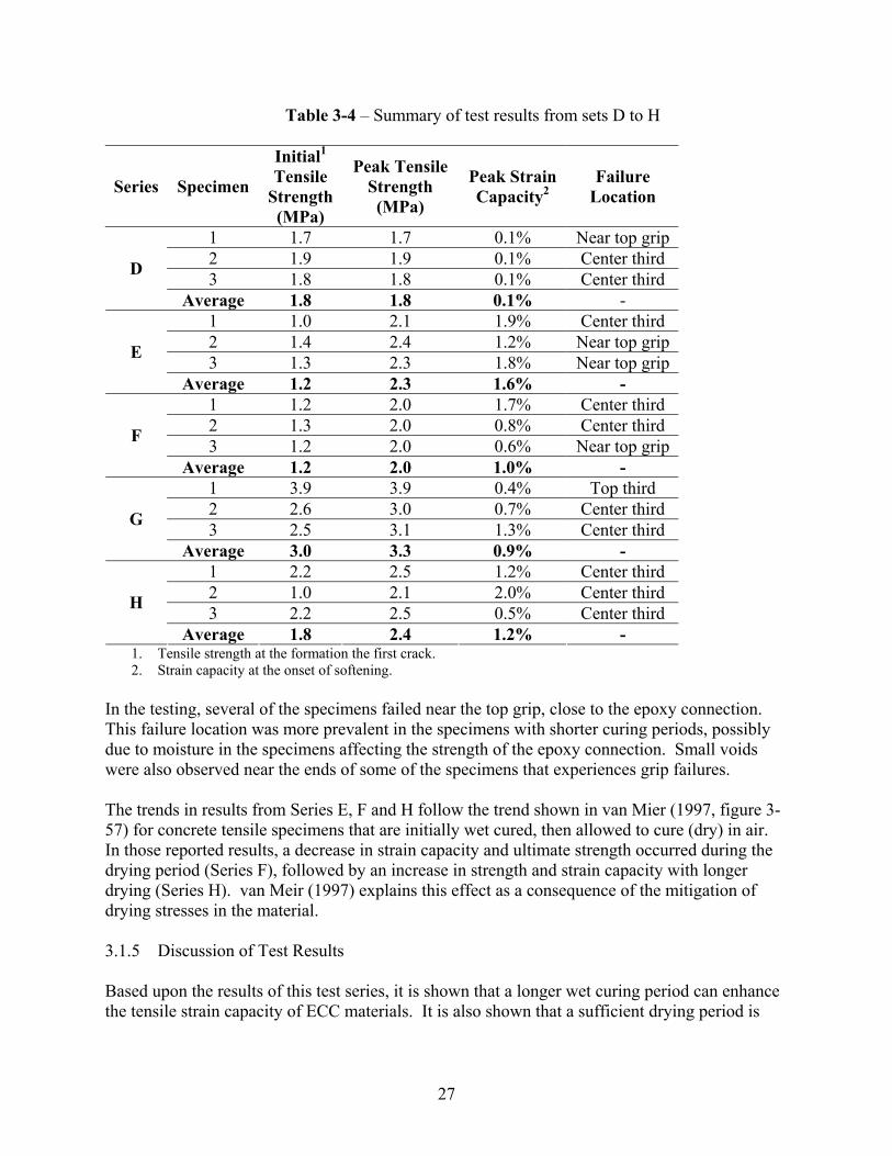
Table 3-4 – Summary of test results from sets D to H
Series Specimen
Initial1 Tensile
Strength (MPa)
Peak Tensile Strength
(MPa)
Peak Strain Capacity2
Failure Location
1 1.7 1.7 0.1% Near top grip 2 1.9 1.9 0.1% Center third 3 1.8 1.8 0.1% Center third D
Average 1.8 1.8 0.1% - 1 1.0 2.1 1.9% Center third 2 1.4 2.4 1.2% Near top grip 3 1.3 2.3 1.8% Near top grip E
Average 1.2 2.3 1.6% - 1 1.2 2.0 1.7% Center third 2 1.3 2.0 0.8% Center third 3 1.2 2.0 0.6% Near top grip F
Average 1.2 2.0 1.0% - 1 3.9 3.9 0.4% Top third 2 2.6 3.0 0.7% Center third 3 2.5 3.1 1.3% Center third G
Average 3.0 3.3 0.9% - 1 2.2 2.5 1.2% Center third 2 1.0 2.1 2.0% Center third 3 2.2 2.5 0.5% Center third H
Average 1.8 2.4 1.2% - 1. Tensile strength at the formation the first crack. 2. Strain capacity at the onset of softening.
In the testing, several of the specimens failed near the top grip, close to the epoxy connection. This failure location was more prevalent in the specimens with shorter curing periods, possibly due to moisture in the specimens affecting the strength of the epoxy connection. Small voids were also observed near the ends of some of the specimens that experiences grip failures. The trends in results from Series E, F and H follow the trend shown in van Mier (1997, figure 3-57) for concrete tensile specimens that are initially wet cured, then allowed to cure (dry) in air. In those reported results, a decrease in strain capacity and ultimate strength occurred during the drying period (Series F), followed by an increase in strength and strain capacity with longer drying (Series H). van Meir (1997) explains this effect as a consequence of the mitigation of drying stresses in the material. 3.1.5 Discussion of Test Results Based upon the results of this test series, it is shown that a longer wet curing period can enhance the tensile strain capacity of ECC materials. It is also shown that a sufficient drying period is
28
necessary to mitigate the effects of shrinkage strains prior to testing. Both of these findings were adopted in the remaining testing. In the tensile testing, the failure of the specimens was often initiated at internal flaws in the specimens. In some of the test series, Series C and H in particular, the presence of an internal flaw in one specimen led to significant decreases in the average strain capacity of the set. The effect of internal flaws is not discussed in previous literature on ECC materials, and was not expected in these test results. The sensitivity to flaws was, possibly, more pronounced in the current research due to the use of thicker (25 mm thick versus the 12.7 mm thick used by Li (1998)) specimens. The impact of internal flaws on the results highlights the need for careful fabrication of the specimens. To prevent the formation of large voids (“bugholes”), both mechanical consolidation and electrical vibration of the specimens is recommended. Mitigation of internal flaws will become a more critical issue in the casting of larger (structural-scale) ECC elements. Larger elements will also need additional drying time for the mitigation of moisture gradients prior to the use of ECC elements in a structure. 3.1.6 Summary of Curing and Drying Study The results of the curing and drying study indicated that extended wet curing and a drying period was necessary to maximize the tensile strain capacity of ECC materials. The sensitivity of ECC to different curing and drying conditions has not previously been documented in the literature. The tensile test results also indicated that ECC materials in tensile tests were sensitive to the presence of internal flaws. The longer curing period and drying period were adopted in the remaining testing reported here. 3.2 Evaluation of Tensile Specimen Geometry The objectives of this research included providing tensile test data for the development of constitutive models for finite element-based simulations. In particular, uniaxial tensile test properties were needed to examine the response of the ECC to varying tensile load conditions. Uniaxial tension tests are not commonly performed on cementitious materials; typically the tensile strength is inferred from indirect tensile tests such as split cylinder or modulus of rupture tests (Mehta, 1986). Split cylinder and modulus of rupture tests provide only an indirect assessment of the uniaxial tension strength of materials, and do not provide the type of information, such as stress-strain response, fracture energy, loading and unloading behavior, etc., that is needed for the development of constitutive models. Currently there is no standard method for tension testing that can provide the necessary information for constitutive model development. In the current research, the tensile strength and strain capacity of ECC materials was tested in uniaxial tension using three different tensile specimen geometries, a rectangular prism specimen (see figure 3-2), a dog-bone shaped specimen and a cylindrical specimen. Figure 3-6 shows the geometry of the dogbone and cylindrical specimens. The goal of the testing was to examine the uniaxial tension response from the different specimen geometries. Again, this information was

29
ultimately used to guide constitutive model development for finite element-based simulations. In previous research, various sizes of prismatic and dogbone shaped tension specimens have been tested although never compared directly (Kelly, 1972, Li, 1998, and Li et al., 2001, Billington and Kesner, 2001). Dogbone shaped specimens are commonly used in tensile testing because the reduced cross-section allows for a uniform tensile stress on the sample. The dogbone shape also helps to eliminate the effects of end conditions by locating the expected failure region away from the specimen ends. The cylindrical specimens were selected in addition to the typically used dogbone geometry because of their standard use in compression testing of cementitious materials. Similar to the prism specimens, load was applied to the dogbone and cylindrical specimens through end caps epoxied to the specimen ends. A swivel was used on top of both the dogbone and cylindrical specimens to help eliminate the introduction of bending stresses in the specimens during testing.
Figure 3-6. Dogbone (a) and cylinder specimens (b) used in uniaxial tension testing (Drawings not to scale)
3.2.1 Test Series To examine the response from the different geometries, a series of 9 specimens (3 for each geometry) was fabricated using the SP mix design shown in table 3-2. The specimens were cast using the procedure described in Section 3.1.1. Different batches of material were prepared for each of the three tested geometries. Consistent with the results presented in the previous section,
(a) (b)
DFRCCCylinder(50mm
diameter)
LVD
T
LVD
T
Swivel
Bolt to test frame
End cap
100m
mECC
Cylinder(50mm
diameter)
LVD
T
LVD
T
Swivel
Bolt to test frame
End cap
100m
m10
0mm
(a) (b)
Swivel
DFRCCDogbone
LVD
T
End cap
Bolt to test frame
25mm x 25mm cross-section
LVD
T
Swivel
DFRCCDogbone
Swivel
ECCDogbone
LVD
T
End cap
Bolt to test frame
cross-section
50m
mLVD
T
25mm x 25mm
(a) (b)
DFRCCCylinder(50mm
diameter)
LVD
T
LVD
T
Swivel
Bolt to test frame
End cap
100m
mECC
Cylinder(50mm
diameter)
LVD
T
LVD
T
Swivel
Bolt to test frame
End cap
100m
m10
0mm
DFRCCCylinder(50mm
diameter)
LVD
T
LVD
T
Swivel
Bolt to test frame
End cap
100m
mECC
Cylinder(50mm
diameter)
LVD
T
LVD
T
Swivel
Bolt to test frame
End cap
100m
m10
0mm
(a) (b)
Swivel
DFRCCDogbone
LVD
T
End cap
Bolt to test frame
25mm x 25mm cross-section
LVD
T
Swivel
DFRCCDogbone
Swivel
ECCDogbone
LVD
T
End cap
Bolt to test frame
cross-section
50m
mLVD
T
25mm x 25mm
30
the specimens were wet cured for 28 days, and then allowed to dry to an equilibrium weight prior to testing. Two different testing setups were used in the testing. The prism specimens were tested in a 25 kN closed loop testing frame, using the test setup described in Section 3.1.1. The testing was stopped when the displacement limit of the LVDTs was reached (at approximately 3.5% strain) or the specimen lost a significant portion of its tensile strength (approximately 60% loss). The dogbone and cylinder specimens were tested in a 225 kN closed loop test frame, using two LVDTs to record the specimen displacement (figure 3-6). On the dogbone specimens the displacement was measured over a 50 mm gage length on the central straight portion of the specimen. On the cylindrical specimens, the displacement was measured over the full 100 mm length of the specimen. In the test setup used on the 225 kN machine, the measured displacement from the LVDTs was used as the control parameter in the testing. Thus, the actuator of the testing machine was controlled by the displacement measured on the specimen. This control method eliminated the need to use the actuator displacement as the control mechanism. Use of the actuator displacement was undesirable because its displacement was influenced by the flexibility of the testing machine. The LVDTs used in the testing had a displacement capacity of 5 mm. This provided an upper limit of 5% on the strain capacity of the cylinder specimens and 10% on the dogbone specimens. All specimens were tested until complete tensile failure, or until the strain capacity of the LVDTs was exceeded. In a few cases, testing of the dogbone specimens was stopped at 5% tensile strain, prior to complete tensile failure. 3.2.2 Test Results The results of the uniaxial tension testing revealed significant variations in both the strength and strain capacity between the different geometries. A representative test result from the different geometries is shown in figure 3-7, with the results from the sets of specimens shown in figures 3.8, 3.9 and 3.10 for the dogbone, prism and cylinder geometries, respectively. Note, that the scale on the x-axis (strain) varies in the figures. The testing results are summarized in table 3-5. The results indicated that the dogbone specimens had both the highest average strength and strain capacity, followed by the prism and cylinder geometries, which were very similar.
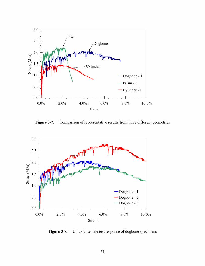
31
Figure 3-7. Comparison of representative results from three different geometries
Figure 3-8. Uniaxial tensile test response of dogbone specimens
0.0
0.5
1.0
1.5
2.0
2.5
3.0
0.0% 2.0% 4.0% 6.0% 8.0% 10.0%Strain
Stre
ss (M
Pa)
Dogbone - 1Dogbone - 2Dogbone - 3
0.0
0.5
1.0
1.5
2.0
2.5
3.0
0.0% 2.0% 4.0% 6.0% 8.0% 10.0%
Strain
Stre
ss (M
Pa)
Dogbone - 1
Prism - 1
Cylinder - 1
Dogbone
Prism
Cylinder
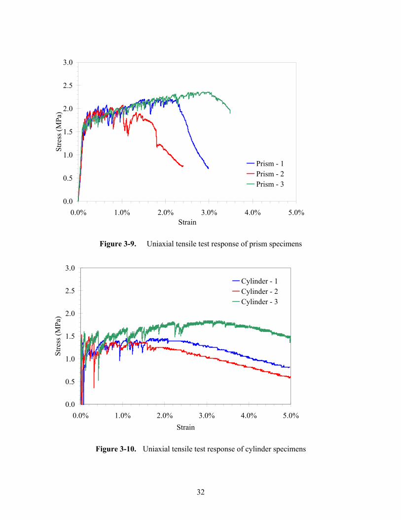
32
Figure 3-9. Uniaxial tensile test response of prism specimens
0.0
0.5
1.0
1.5
2.0
2.5
3.0
0.0% 1.0% 2.0% 3.0% 4.0% 5.0%Strain
Stre
ss (M
Pa)
Cylinder - 1Cylinder - 2Cylinder - 3
Figure 3-10. Uniaxial tensile test response of cylinder specimens
0.0
0.5
1.0
1.5
2.0
2.5
3.0
0.0% 1.0% 2.0% 3.0% 4.0% 5.0%Strain
Stre
ss (M
Pa)
Prism - 1Prism - 2Prism - 3
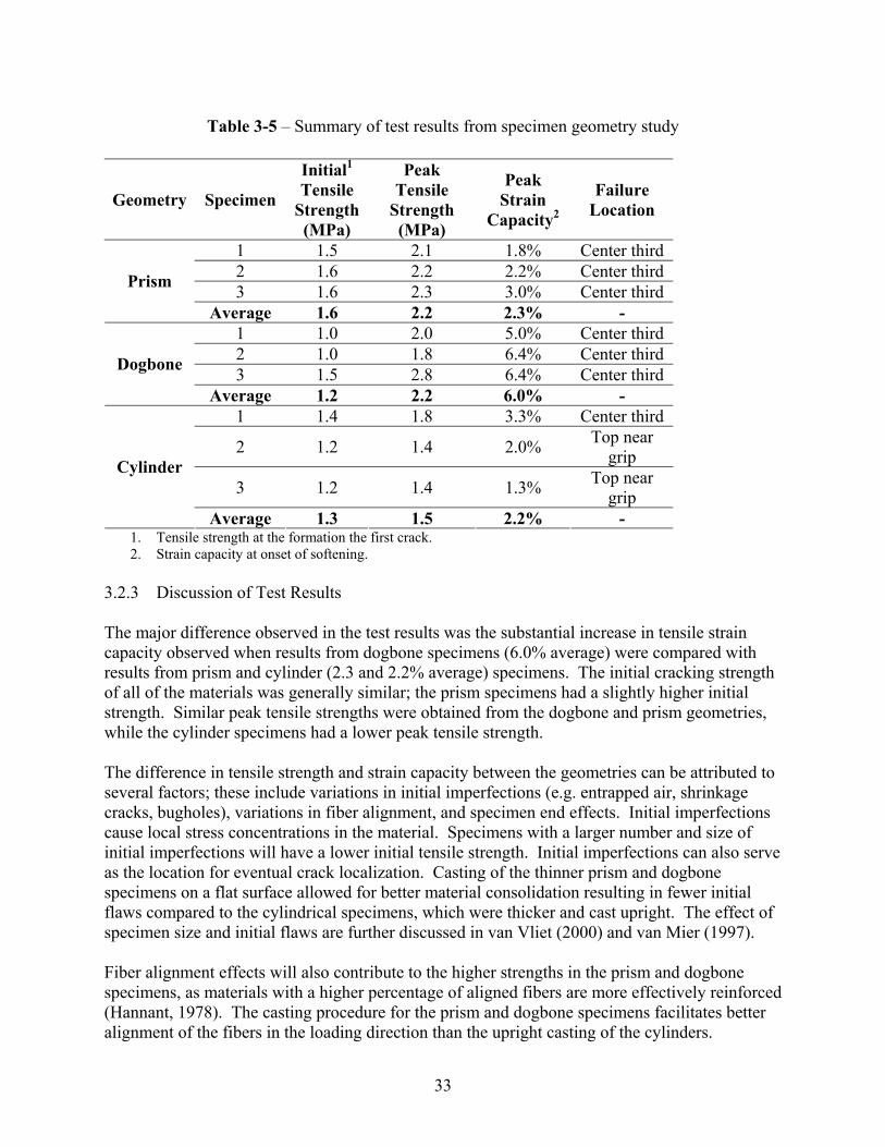
33
Table 3-5 – Summary of test results from specimen geometry study
Geometry Specimen
Initial1 Tensile
Strength (MPa)
Peak Tensile
Strength (MPa)
Peak Strain
Capacity2
Failure Location
1 1.5 2.1 1.8% Center third 2 1.6 2.2 2.2% Center third 3 1.6 2.3 3.0% Center third Prism
Average 1.6 2.2 2.3% - 1 1.0 2.0 5.0% Center third 2 1.0 1.8 6.4% Center third 3 1.5 2.8 6.4% Center third Dogbone
Average 1.2 2.2 6.0% - 1 1.4 1.8 3.3% Center third
2 1.2 1.4 2.0% Top near grip
3 1.2 1.4 1.3% Top near grip
Cylinder
Average 1.3 1.5 2.2% - 1. Tensile strength at the formation the first crack. 2. Strain capacity at onset of softening.
3.2.3 Discussion of Test Results The major difference observed in the test results was the substantial increase in tensile strain capacity observed when results from dogbone specimens (6.0% average) were compared with results from prism and cylinder (2.3 and 2.2% average) specimens. The initial cracking strength of all of the materials was generally similar; the prism specimens had a slightly higher initial strength. Similar peak tensile strengths were obtained from the dogbone and prism geometries, while the cylinder specimens had a lower peak tensile strength. The difference in tensile strength and strain capacity between the geometries can be attributed to several factors; these include variations in initial imperfections (e.g. entrapped air, shrinkage cracks, bugholes), variations in fiber alignment, and specimen end effects. Initial imperfections cause local stress concentrations in the material. Specimens with a larger number and size of initial imperfections will have a lower initial tensile strength. Initial imperfections can also serve as the location for eventual crack localization. Casting of the thinner prism and dogbone specimens on a flat surface allowed for better material consolidation resulting in fewer initial flaws compared to the cylindrical specimens, which were thicker and cast upright. The effect of specimen size and initial flaws are further discussed in van Vliet (2000) and van Mier (1997). Fiber alignment effects will also contribute to the higher strengths in the prism and dogbone specimens, as materials with a higher percentage of aligned fibers are more effectively reinforced (Hannant, 1978). The casting procedure for the prism and dogbone specimens facilitates better alignment of the fibers in the loading direction than the upright casting of the cylinders.

34
Finally, specimen end effects may also contribute to the observed variation in peak strength between the three geometries. Both the cylindrical and prism specimens will have some non-uniformity in stress at the ends of the specimens due to differences in Poisson’s ratio for the ECC and the steel end plates. This effect will not occur in the reduced section of the dogbone specimens. Localized cracks near the ends of the specimens were observed in the some of the cylindrical and prism specimens, which could be from a combination of initial imperfections and the non-uniformity in stress near the ends. 3.2.4 Summary of Test Results Significant differences were observed in the uniaxial tensile response of ECC materials with different specimen geometries. The difference in size of the three geometries studied would, in particular, affect the number and size of initial imperfections, which could alter the material’s strain hardening capacity. To develop material models, the results from the prism and cylinder specimens were most appropriate. Direct use of the dogbone results will, in all probability, result in over estimations of the strain capacity of ECC in structural applications. Further investigation is needed to understand and predict the performance of ECC materials in applications of varying size and geometry.
3.3 Evaluation of Different Fibers in ECC Materials In this section, several different fibers were examined for potential use in ECC materials. The goal of evaluating different fibers was to verify that the response of ECC materials made with different fiber types was consistent with the background theory summarized in Section 2, and in the literature. The evaluation of different fibers was motivated primarily by cost, since a fiber with a lower cost (PVA fiber) and similar performance will be advantageous over a more expensive fiber (UHMWPE fiber). 3.3.1 Previous Work In previous research, both in the literature (Li, 1998) and in the preceding sections, a UHMWPE fiber (trade name Spectra) was found to provide the right combination of fiber geometry and mechanical properties for use in ECC materials. In the original development of ECC material, several other fiber types were examined in addition to the UHMWPE fibers (Li and Leung, 1992). Other fiber types included steel, polypropylene, fiberglass, and polyvinyl alcohol fibers (see table 2-1). The initial examination concluded that the steel, polyvinyl alcohol and UHMWPE fibers possessed the necessary combination of geometry and mechanical properties to create the desired tensile response. The UHMWPE fibers were typically selected for further research as they provided tensile strain hardening with the lowest volume fraction of fibers (Li and Leung, 1992). 3.3.2 Fibers Examined In this investigation, three new commercially available fibers were evaluated, described in table 3-6. One of the fibers (trade name Dyneema) is also a UHMWPE fiber. However the Dyneema
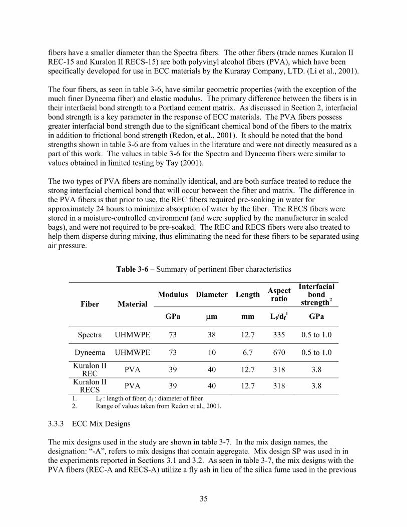
35
fibers have a smaller diameter than the Spectra fibers. The other fibers (trade names Kuralon II REC-15 and Kuralon II RECS-15) are both polyvinyl alcohol fibers (PVA), which have been specifically developed for use in ECC materials by the Kuraray Company, LTD. (Li et al., 2001). The four fibers, as seen in table 3-6, have similar geometric properties (with the exception of the much finer Dyneema fiber) and elastic modulus. The primary difference between the fibers is in their interfacial bond strength to a Portland cement matrix. As discussed in Section 2, interfacial bond strength is a key parameter in the response of ECC materials. The PVA fibers possess greater interfacial bond strength due to the significant chemical bond of the fibers to the matrix in addition to frictional bond strength (Redon, et al., 2001). It should be noted that the bond strengths shown in table 3-6 are from values in the literature and were not directly measured as a part of this work. The values in table 3-6 for the Spectra and Dyneema fibers were similar to values obtained in limited testing by Tay (2001). The two types of PVA fibers are nominally identical, and are both surface treated to reduce the strong interfacial chemical bond that will occur between the fiber and matrix. The difference in the PVA fibers is that prior to use, the REC fibers required pre-soaking in water for approximately 24 hours to minimize absorption of water by the fiber. The RECS fibers were stored in a moisture-controlled environment (and were supplied by the manufacturer in sealed bags), and were not required to be pre-soaked. The REC and RECS fibers were also treated to help them disperse during mixing, thus eliminating the need for these fibers to be separated using air pressure.
Table 3-6 – Summary of pertinent fiber characteristics
Modulus Diameter Length Aspect ratio
Interfacial bond
strength2 Fiber Material GPa µm mm Lf/df
1 GPa
Spectra UHMWPE 73 38 12.7 335 0.5 to 1.0
Dyneema UHMWPE 73 10 6.7 670 0.5 to 1.0 Kuralon II
REC PVA 39 40 12.7 318 3.8 Kuralon II
RECS PVA 39 40 12.7 318 3.8 1. Lf : length of fiber; df : diameter of fiber 2. Range of values taken from Redon et al., 2001.
3.3.3 ECC Mix Designs The mix designs used in the study are shown in table 3-7. In the mix design names, the designation: “-A”, refers to mix designs that contain aggregate. Mix design SP was used in in the experiments reported in Sections 3.1 and 3.2. As seen in table 3-7, the mix designs with the PVA fibers (REC-A and RECS-A) utilize a fly ash in lieu of the silica fume used in the previous
36
tests. The PVA fiber mix designs also utilize another admixture, methylcellulose, in addition to the superplastizer. The methylcellulose acts as a fluidifying agent during mixing, and helps to prevent the settlement of the fibers from the mix during mixing and casting. The higher specific gravity of the PVA fibers (1.3 compared to 0.97 for UHMWPE) makes them potentially prone to settlement to the bottom of specimens during casting. The use of fly ash, methylcellulose, and the proportions were based upon mix designs provided by the fiber manufacturer (Kuraray, 2002). In the majority of the tested materials, a fine aggregate1 (<0.3 mm) was used. The size of the aggregates in the matrix must be limited to minimize the matrix fracture toughness of the resulting composites (Section 2.1.5 and Li, et al., 1995). The use of aggregates helps reduce the creep and drying shrinkage of the specimens (Billington and Rouse, 2003), and also reduces the cost of the material. All of the specimens examined in this study were wet cured for 28 days prior to testing. At the end of the wet curing period, the specimens were allowed to dry for a minimum of 14 days under laboratory conditions prior to testing.
1 F-70 Silica Sand by US Silica. (http://www.u-s-silica.com/prod_info/PDS/Ottawa/ottawaFs2002.PDF)
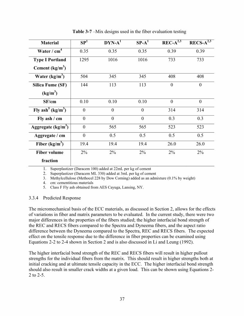
37
Table 3-7 –Mix designs used in the fiber evaluation testing
Material SP1 DYN-A1 SP-A1 REC-A2,3 RECS-A2,3
Water / cm4 0.35 0.35 0.35 0.39 0.39
Type I Portland
Cement (kg/m3)
1295 1016 1016 733 733
Water (kg/m3) 504 345 345 408 408
Silica Fume (SF)
(kg/m3)
144 113 113 0 0
SF/cm 0.10 0.10 0.10 0 0
Fly ash5 (kg/m3) 0 0 0 314 314
Fly ash / cm 0 0 0 0.3 0.3
Aggregate (kg/m3) 0 565 565 523 523
Aggregate / cm 0 0.5 0.5 0.5 0.5
Fiber (kg/m3) 19.4 19.4 19.4 26.0 26.0
Fiber volume
fraction
2% 2% 2% 2% 2%
1. Superplastizer (Daracem 100) added at 22mL per kg of cement 2. Superplastizer (Daracem ML 330) added at 3mL per kg of cement 3. Methylcellulose (Methocel 228 by Dow Corning) added as an admixture (0.1% by weight) 4. cm: cementitious materials 5. Class F Fly ash obtained from AES Cayuga, Lansing, NY.
3.3.4 Predicted Response The micromechanical basis of the ECC materials, as discussed in Section 2, allows for the effects of variations in fiber and matrix parameters to be evaluated. In the current study, there were two major differences in the properties of the fibers studied; the higher interfacial bond strength of the REC and RECS fibers compared to the Spectra and Dyneema fibers, and the aspect ratio difference between the Dyneema compared to the Spectra, REC and RECS fibers. The expected effect on the tensile response due to the difference in fiber properties can be examined using Equations 2-2 to 2-4 shown in Section 2 and is also discussed in Li and Leung (1992). The higher interfacial bond strength of the REC and RECS fibers will result in higher pullout strengths for the individual fibers from the matrix. This should result in higher strengths both at initial cracking and at ultimate tensile capacity in the ECC. The higher interfacial bond strength should also result in smaller crack widths at a given load. This can be shown using Equations 2-2 to 2-5.
38
The use of the same volume fraction of the smaller diameter (higher aspect ratio) Dyneema fibers will result in ECC samples with a higher number of individual fibers when compared to samples with Spectra, REC or RECS fibers. Assuming the matrix and fiber material properties remain constant, the fibers with the higher aspect ratio should have smaller crack widths for a given load (Equation 2-2 to 2-4). In addition, as the diameter of the fibers decrease, the first crack strength should increase. The fibers with a higher aspect ratio should also provide a higher bridging stress, allowing a higher ultimate strength (Equation 2-5). Predictions of the strain capacity of the materials cannot be readily made from an examination of the fiber and matrix properties. The inability to predict strain capacity is a consequence of the random internal flaws in the materials, which act to limit the strain capacity of the materials. The inability to predict tensile strain capacity can be seen in the preceding section, where tension tests showed large variations in strain capacity with test geometries, despite testing nominally identical materials. 3.3.5 Test Series To examine the effect of the different fibers, a series of three dogbone and three cylinder specimens were cast using each of the mix designs shown in table 3-7. One exception was that cylinder specimens were not cast with mix design DYN-A. The dogbone geometry was selected for the fiber evaluation because it provided the most ductile response in the geometry evaluation (Section 3.2). The cylinders were selected because they represent the most common geometry for testing of cementitious materials. Uniaxial tensile tests were performed on the specimens using the procedure described in Section 3.2.1 in the 225 kN testing machine. Testing was carried out until complete failure of the specimens as defined by exceeding the displacement limit of the LVDT’s or a greater than 60% loss from the peak tensile strength. The testing of some of the dogbone specimens (indicated in the results) was stopped at 5% strain.
3.3.6 Test Results Representative uniaxial tension test results from the dogbone specimens are shown in figure 3-11, while representative results from the cylindrical specimens are shown in figure 3-12. The number following the mix design name (1, 2, or 3) refers to the specimen number from that particular set. Similar to the results presented in Section 3.2, the cylindrical specimens had both lower strengths and strain capacities compared to the dogbone geometry. Figures 3.13 to 3.19 show the results from the tests of each mix design that contained aggregate (note the x-axis scales differ). The results from the SP mix designs, without aggregate, are shown in figures 3.8 and 3.10. The testing results are summarized in tables 3-8 and 3-9 for the dogbone and cylindrical geometries, respectively. Consistent with theory, the specimens made with the higher aspect ratio Dyneema fibers (DYN-A) had visibly finer cracks widths when compared to specimens the Spectra fibers. Similarly, the use of REC and RECS fibers also resulted in visibly finer crack widths, due to greater bond strength compared to the Spectra fibers.

39
Figure 3-11. Comparison of uniaxial tensile test results from dogbone specimens (Specimen SP-A stopped at 5% strain)
Figure 3-12. Comparison of uniaxial tensile test results from cylindrical specimens
0.0
1.0
2.0
3.0
4.0
0.0% 1.0% 2.0% 3.0% 4.0% 5.0% 6.0%
Strain
Stre
ss (M
Pa)
SP - 2SP-A - 3REC-A - 1RECS-A - 1
RECS-A - 1
REC-A - 1
SP - 2 SP-A - 3
0.0
1.0
2.0
3.0
4.0
5.0
6.0
0.0% 2.0% 4.0% 6.0% 8.0% 10.0%
Strain
Stre
ss (M
Pa)
SP - 1SP-A - 3DYN-A - 1REC-A - 2RECS-A - 3
RECS-A - 3REC-A - 2
DYN-A - 1
SP - 1SP-A - 3
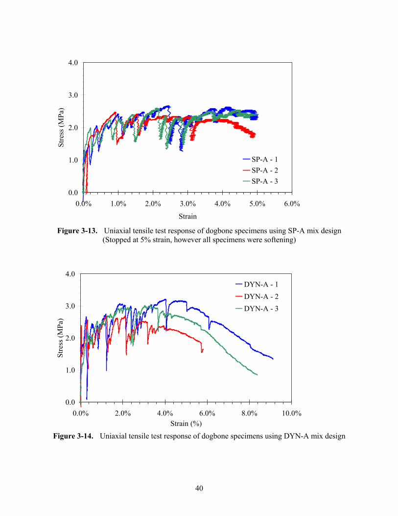
40
Figure 3-13. Uniaxial tensile test response of dogbone specimens using SP-A mix design (Stopped at 5% strain, however all specimens were softening)
Figure 3-14. Uniaxial tensile test response of dogbone specimens using DYN-A mix design
0.0
1.0
2.0
3.0
4.0
0.0% 1.0% 2.0% 3.0% 4.0% 5.0% 6.0%
Strain
Stre
ss (M
Pa)
SP-A - 1SP-A - 2SP-A - 3
0.0
1.0
2.0
3.0
4.0
0.0% 2.0% 4.0% 6.0% 8.0% 10.0%Strain (%)
Stre
ss (M
Pa)
DYN-A - 1DYN-A - 2DYN-A - 3
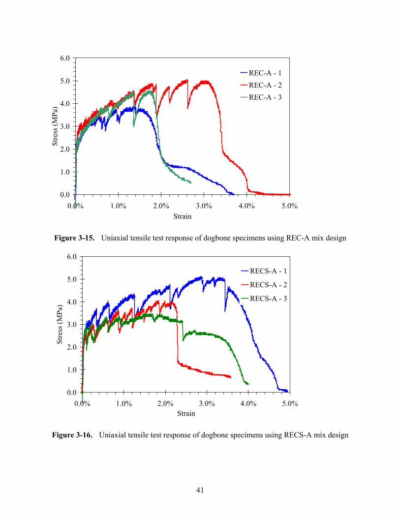
41
Figure 3-15. Uniaxial tensile test response of dogbone specimens using REC-A mix design
Figure 3-16. Uniaxial tensile test response of dogbone specimens using RECS-A mix design
0.0
1.0
2.0
3.0
4.0
5.0
6.0
0.0% 1.0% 2.0% 3.0% 4.0% 5.0%Strain
Stre
ss (M
Pa)
RECS-A - 1
RECS-A - 2
RECS-A - 3
0.0
1.0
2.0
3.0
4.0
5.0
6.0
0.0% 1.0% 2.0% 3.0% 4.0% 5.0%Strain
Stre
ss (M
Pa)
REC-A - 1REC-A - 2REC-A - 3

42
Figure 3-17. Uniaxial tensile test response of cylinder specimens using SP-A mix design
Figure 3-18. Uniaxial tensile test response of cylinder specimens using REC-A mix design
0.0
1.0
2.0
3.0
4.0
0.0% 1.0% 2.0% 3.0% 4.0% 5.0%
Strain
Stre
ss (M
Pa)
SP-A - 1SP-A - 2SP-A - 3
0.0
1.0
2.0
3.0
4.0
0.0% 1.0% 2.0% 3.0% 4.0% 5.0%Strain
Stre
ss (M
Pa)
REC-A - 1REC-A - 2REC-A - 3
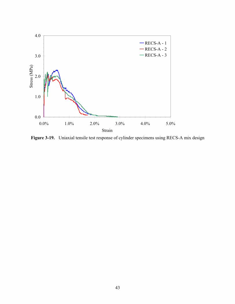
43
Figure 3-19. Uniaxial tensile test response of cylinder specimens using RECS-A mix design
0.0
1.0
2.0
3.0
4.0
0.0% 1.0% 2.0% 3.0% 4.0% 5.0%Strain
Stre
ss (M
Pa)
RECS-A - 1RECS-A - 2RECS-A - 3
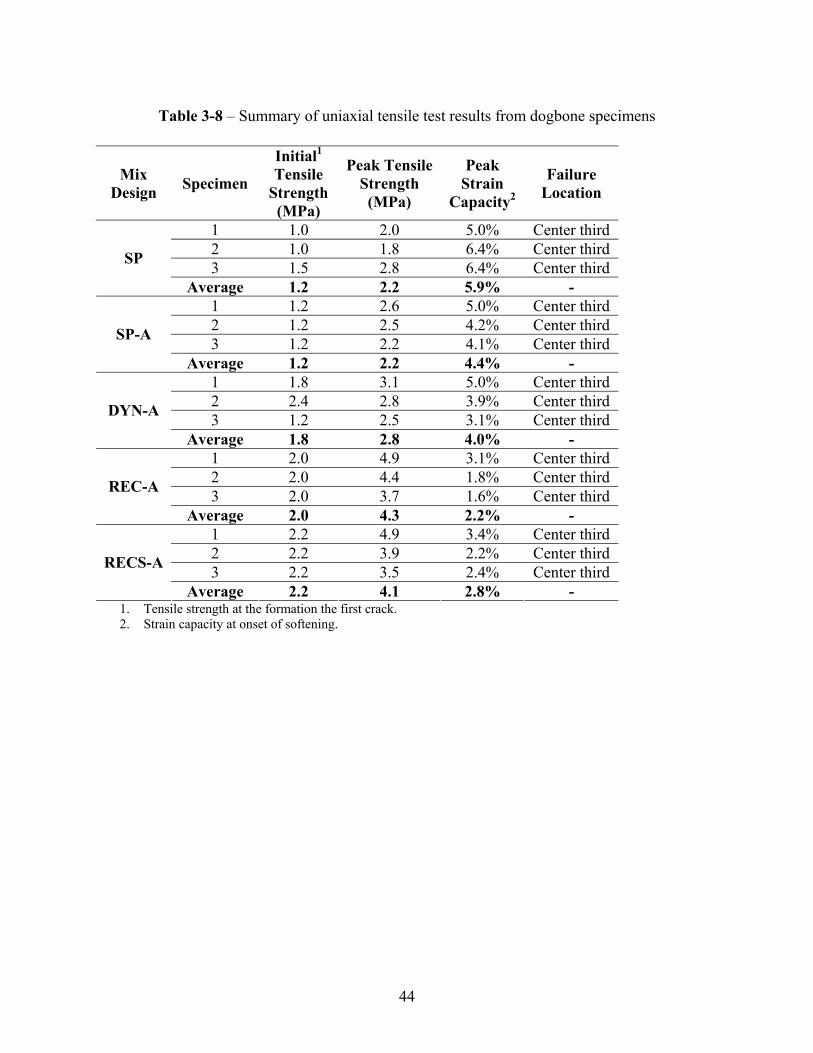
44
Table 3-8 – Summary of uniaxial tensile test results from dogbone specimens
Mix Design Specimen
Initial1 Tensile
Strength (MPa)
Peak Tensile Strength (MPa)
Peak Strain
Capacity2
Failure Location
1 1.0 2.0 5.0% Center third 2 1.0 1.8 6.4% Center third 3 1.5 2.8 6.4% Center third SP
Average 1.2 2.2 5.9% - 1 1.2 2.6 5.0% Center third 2 1.2 2.5 4.2% Center third 3 1.2 2.2 4.1% Center third SP-A
Average 1.2 2.2 4.4% - 1 1.8 3.1 5.0% Center third 2 2.4 2.8 3.9% Center third 3 1.2 2.5 3.1% Center third DYN-A
Average 1.8 2.8 4.0% - 1 2.0 4.9 3.1% Center third 2 2.0 4.4 1.8% Center third 3 2.0 3.7 1.6% Center third REC-A
Average 2.0 4.3 2.2% - 1 2.2 4.9 3.4% Center third 2 2.2 3.9 2.2% Center third 3 2.2 3.5 2.4% Center third RECS-A
Average 2.2 4.1 2.8% - 1. Tensile strength at the formation the first crack. 2. Strain capacity at onset of softening.
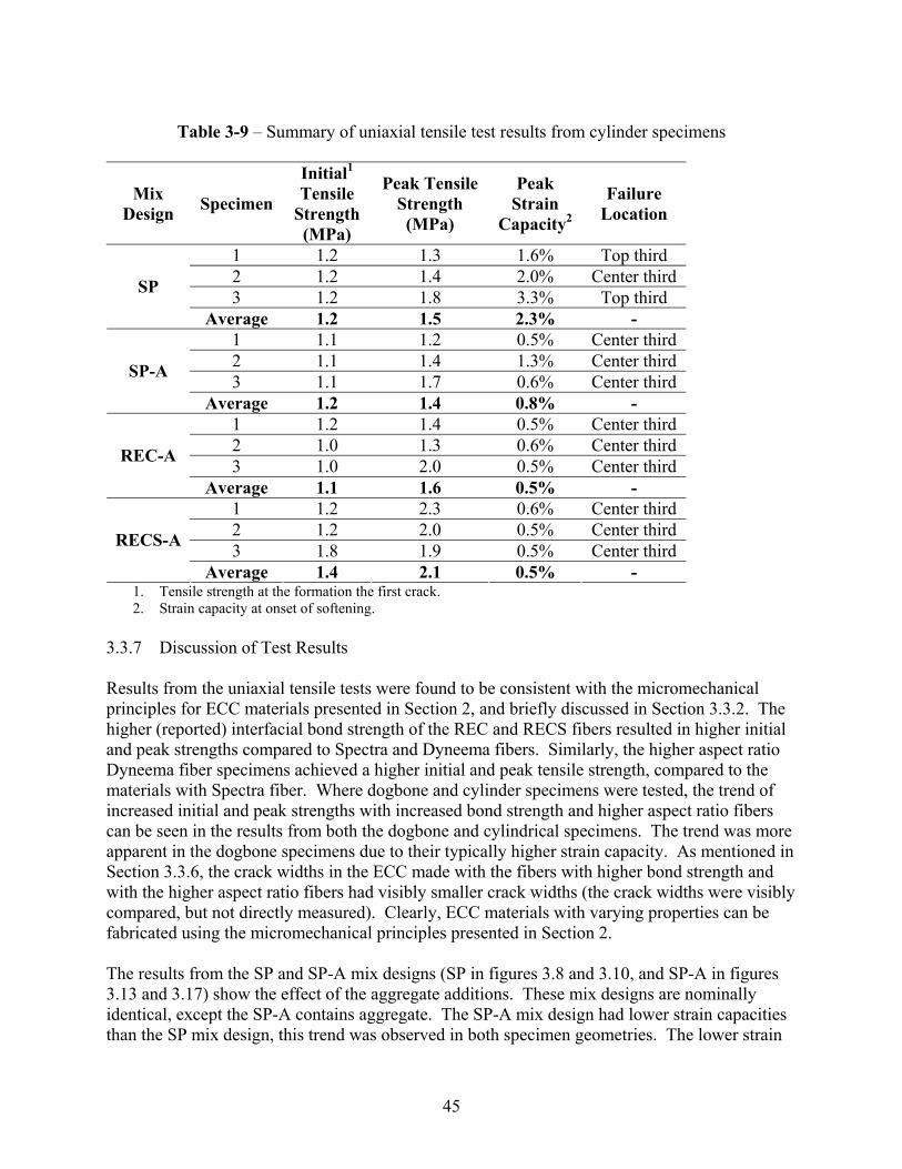
45
Table 3-9 – Summary of uniaxial tensile test results from cylinder specimens
Mix Design Specimen
Initial1 Tensile
Strength (MPa)
Peak Tensile Strength (MPa)
Peak Strain
Capacity2
Failure Location
1 1.2 1.3 1.6% Top third 2 1.2 1.4 2.0% Center third 3 1.2 1.8 3.3% Top third SP
Average 1.2 1.5 2.3% - 1 1.1 1.2 0.5% Center third 2 1.1 1.4 1.3% Center third 3 1.1 1.7 0.6% Center third SP-A
Average 1.2 1.4 0.8% - 1 1.2 1.4 0.5% Center third 2 1.0 1.3 0.6% Center third 3 1.0 2.0 0.5% Center third REC-A
Average 1.1 1.6 0.5% - 1 1.2 2.3 0.6% Center third 2 1.2 2.0 0.5% Center third 3 1.8 1.9 0.5% Center third RECS-A
Average 1.4 2.1 0.5% - 1. Tensile strength at the formation the first crack. 2. Strain capacity at onset of softening.
3.3.7 Discussion of Test Results Results from the uniaxial tensile tests were found to be consistent with the micromechanical principles for ECC materials presented in Section 2, and briefly discussed in Section 3.3.2. The higher (reported) interfacial bond strength of the REC and RECS fibers resulted in higher initial and peak strengths compared to Spectra and Dyneema fibers. Similarly, the higher aspect ratio Dyneema fiber specimens achieved a higher initial and peak tensile strength, compared to the materials with Spectra fiber. Where dogbone and cylinder specimens were tested, the trend of increased initial and peak strengths with increased bond strength and higher aspect ratio fibers can be seen in the results from both the dogbone and cylindrical specimens. The trend was more apparent in the dogbone specimens due to their typically higher strain capacity. As mentioned in Section 3.3.6, the crack widths in the ECC made with the fibers with higher bond strength and with the higher aspect ratio fibers had visibly smaller crack widths (the crack widths were visibly compared, but not directly measured). Clearly, ECC materials with varying properties can be fabricated using the micromechanical principles presented in Section 2. The results from the SP and SP-A mix designs (SP in figures 3.8 and 3.10, and SP-A in figures 3.13 and 3.17) show the effect of the aggregate additions. These mix designs are nominally identical, except the SP-A contains aggregate. The SP-A mix design had lower strain capacities than the SP mix design, this trend was observed in both specimen geometries. The lower strain
46
capacity of the ECC materials with aggregate was consistent with previous research results which showed that aggregate additions have the effect of increasing the fracture toughness of the materials, which results in a lower strain capacity (Li, et al., 1995). The initial and peak tensile strength was not affected by the aggregate addition. The mix designs used in the tests used different supplementary cementitious materials (silica fume and fly ash), and different amounts of the materials. A comparison of the effects of the supplementary cementitious materials was not included in the research, and the limited number of mix designs used in the study precludes direct comparisons on the results of the additions. This topic can be addressed in future research. 3.3.8 Summary of Test Results The results of the testing showed the variation in tensile response that can occur through the use of different fibers and fiber-matrix combinations. The tensile response of the ECC material with different fibers was consistent with the micromechanical principles reviewed in Section 2. Aggregate additions to the ECC were observed to decrease the tensile strain capacity of the materials, but did not have a significant effect on the materials initial or peak tensile strength. Additional study will be required to fully understand effect of different supplementary cementitious materials used in the research. 3.4 Cyclic Testing of ECC Materials This section presents the results of an experimental investigation of ECC materials subjected to monotonic and cyclic uniaxial loading. The main objective of this portion of the research was to identify ECC material response to various cyclic loading schemes. The results were used by colleagues to develop a constitutive model for nonlinear cyclic finite-element analyses (Han et al., 2003). The main variables in the experiments were different mix designs, and different loading schemes. The cyclic response of ECC materials has not been extensively examined to date and was necessary to evaluate the unloading and reloading response of the ECC materials. . Due to the high strain capacity and pseudo-strain hardening of ECC materials it was expected that the cyclic response of ECC materials would be different from conventional concrete materials. For constitutive model development, the complete tensile response of ECC including post-peak behavior must be known. An accurate material model was need for the finite element-based simulations of ECC performance in the retrofit applications being investigated as a part of the larger research project. 3.4.1 Previous Work The cyclic behavior of concrete materials has been extensively studied in previous experimental research (summaries in CEB, 1996 and van Mier, 1997). Numerous constitutive models have also been developed that describe the response of concrete to cyclic compressive and tensile loads (e.g., Sinha, et al. 1964; Karsan and Jirsa, 1969; Yankelevsky and Reinhardt, 1987; and summary in CEB, 1996).
47
The pseudo-strain hardening behavior of ECC materials in tension is significantly different than the tensile behavior of conventional cementitious materials. Therefore direct application of many previously developed models was not possible for the simulation of ECC response to cyclic loading. Kabele (2001) proposed a constitutive model for ECC based on the theoretical micro-mechanics of the material response. This model was used to simulate the cyclic response of ECC infill panels. To date, no material models for ECC have been developed based on reversed cyclic loading experiments. Similarly, very few reversed-cyclic loading experiments have been reported on ECC materials (See Section 2.1.4). Fukuyama, et al. (1999) examined the tension-compression envelope behavior of ECC material made with PVA fibers. In a later study, Sato et al. (2001), and Fukuyama et al., (2002) included multiple loadings in the tensile regime of the loading cycle. The specimens were loaded in tension to predetermined strain levels, unloaded, and then loaded in compression to a stress equivalent to one third of the compressive strength of the material. Following the compressive loading the tensile loading was repeated to a higher strain level. 3.4.2 Test Program To evaluate the cyclic response of ECC materials a testing program was developed with the following objectives:
• Determine the nature of the unloading and reloading behavior of ECC in tension and compression.
• Determine if the results from monotonic uniaxial tests can be used in a cyclic material model.
• Determine if cyclic loadings affect the peak compressive or tensile stress, or the strain at the peak stress levels relative to monotonic response.
• Evaluate how repeatable the results from tests on ECC materials are. The cyclic testing included monotonic uniaxial compression, cyclic uniaxial compression and reversed uniaxial cyclic tension/compression experiments. Cylindrical specimens were used in all of the tests. Unless specifically noted, a minimum of three specimens was tested for each loading condition to evaluate the reproducibility of the results.
3.4.3 Material Composition The testing described in this section utilized the mix designs described in Section 3.3; with the exception of mix DYN-A, which was not used. To develop a greater understanding of the influence of the fibers on the compressive response of the material, additional specimens were cast using the SP and RECS-A mix design without fibers. These mix designs were termed Paste and Mortar, respectively. Table 3-10 shows all the mix designs used in the cyclic testing. The specimens were cast and cured in an identical manner to the specimens described in Section 3.2.
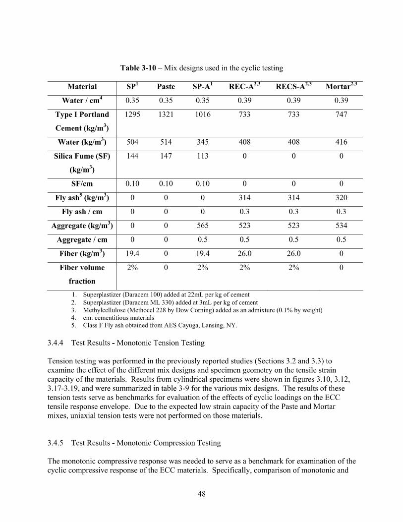
48
Table 3-10 – Mix designs used in the cyclic testing
Material SP1 Paste SP-A1 REC-A2,3 RECS-A2,3 Mortar2,3
Water / cm4 0.35 0.35 0.35 0.39 0.39 0.39
Type I Portland
Cement (kg/m3)
1295 1321 1016 733 733 747
Water (kg/m3) 504 514 345 408 408 416
Silica Fume (SF)
(kg/m3)
144 147 113 0 0 0
SF/cm 0.10 0.10 0.10 0 0 0
Fly ash5 (kg/m3) 0 0 0 314 314 320
Fly ash / cm 0 0 0 0.3 0.3 0.3
Aggregate (kg/m3) 0 0 565 523 523 534
Aggregate / cm 0 0 0.5 0.5 0.5 0.5
Fiber (kg/m3) 19.4 0 19.4 26.0 26.0 0
Fiber volume
fraction
2% 0 2% 2% 2% 0
1. Superplastizer (Daracem 100) added at 22mL per kg of cement 2. Superplastizer (Daracem ML 330) added at 3mL per kg of cement 3. Methylcellulose (Methocel 228 by Dow Corning) added as an admixture (0.1% by weight) 4. cm: cementitious materials 5. Class F Fly ash obtained from AES Cayuga, Lansing, NY.
3.4.4 Test Results - Monotonic Tension Testing Tension testing was performed in the previously reported studies (Sections 3.2 and 3.3) to examine the effect of the different mix designs and specimen geometry on the tensile strain capacity of the materials. Results from cylindrical specimens were shown in figures 3.10, 3.12, 3.17-3.19, and were summarized in table 3-9 for the various mix designs. The results of these tension tests serve as benchmarks for evaluation of the effects of cyclic loadings on the ECC tensile response envelope. Due to the expected low strain capacity of the Paste and Mortar mixes, uniaxial tension tests were not performed on those materials. 3.4.5 Test Results - Monotonic Compression Testing The monotonic compressive response was needed to serve as a benchmark for examination of the cyclic compressive response of the ECC materials. Specifically, comparison of monotonic and
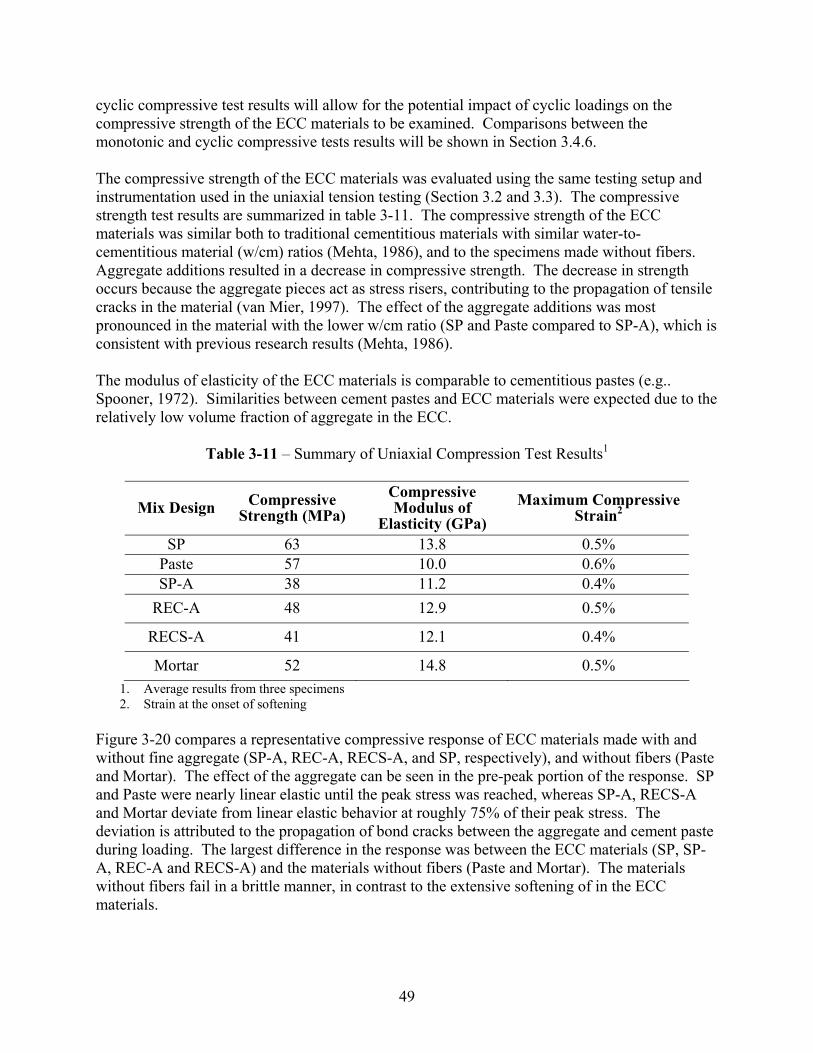
49
cyclic compressive test results will allow for the potential impact of cyclic loadings on the compressive strength of the ECC materials to be examined. Comparisons between the monotonic and cyclic compressive tests results will be shown in Section 3.4.6. The compressive strength of the ECC materials was evaluated using the same testing setup and instrumentation used in the uniaxial tension testing (Section 3.2 and 3.3). The compressive strength test results are summarized in table 3-11. The compressive strength of the ECC materials was similar both to traditional cementitious materials with similar water-to-cementitious material (w/cm) ratios (Mehta, 1986), and to the specimens made without fibers. Aggregate additions resulted in a decrease in compressive strength. The decrease in strength occurs because the aggregate pieces act as stress risers, contributing to the propagation of tensile cracks in the material (van Mier, 1997). The effect of the aggregate additions was most pronounced in the material with the lower w/cm ratio (SP and Paste compared to SP-A), which is consistent with previous research results (Mehta, 1986). The modulus of elasticity of the ECC materials is comparable to cementitious pastes (e.g.. Spooner, 1972). Similarities between cement pastes and ECC materials were expected due to the relatively low volume fraction of aggregate in the ECC.
Table 3-11 – Summary of Uniaxial Compression Test Results1
Mix Design Compressive Strength (MPa)
Compressive Modulus of
Elasticity (GPa) Maximum Compressive
Strain2
SP 63 13.8 0.5% Paste 57 10.0 0.6% SP-A 38 11.2 0.4%
REC-A 48 12.9 0.5%
RECS-A 41 12.1 0.4%
Mortar 52 14.8 0.5% 1. Average results from three specimens 2. Strain at the onset of softening
Figure 3-20 compares a representative compressive response of ECC materials made with and without fine aggregate (SP-A, REC-A, RECS-A, and SP, respectively), and without fibers (Paste and Mortar). The effect of the aggregate can be seen in the pre-peak portion of the response. SP and Paste were nearly linear elastic until the peak stress was reached, whereas SP-A, RECS-A and Mortar deviate from linear elastic behavior at roughly 75% of their peak stress. The deviation is attributed to the propagation of bond cracks between the aggregate and cement paste during loading. The largest difference in the response was between the ECC materials (SP, SP-A, REC-A and RECS-A) and the materials without fibers (Paste and Mortar). The materials without fibers fail in a brittle manner, in contrast to the extensive softening of in the ECC materials.
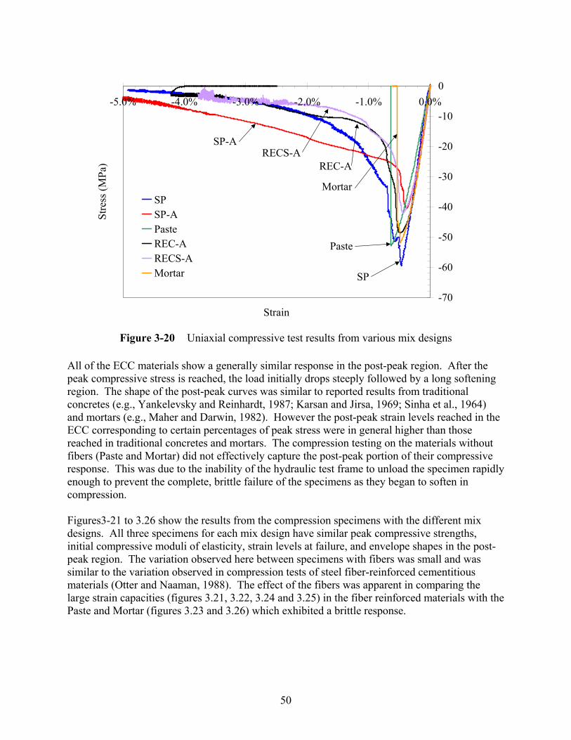
50
Figure 3-20 Uniaxial compressive test results from various mix designs All of the ECC materials show a generally similar response in the post-peak region. After the peak compressive stress is reached, the load initially drops steeply followed by a long softening region. The shape of the post-peak curves was similar to reported results from traditional concretes (e.g., Yankelevsky and Reinhardt, 1987; Karsan and Jirsa, 1969; Sinha et al., 1964) and mortars (e.g., Maher and Darwin, 1982). However the post-peak strain levels reached in the ECC corresponding to certain percentages of peak stress were in general higher than those reached in traditional concretes and mortars. The compression testing on the materials without fibers (Paste and Mortar) did not effectively capture the post-peak portion of their compressive response. This was due to the inability of the hydraulic test frame to unload the specimen rapidly enough to prevent the complete, brittle failure of the specimens as they began to soften in compression. Figures3-21 to 3.26 show the results from the compression specimens with the different mix designs. All three specimens for each mix design have similar peak compressive strengths, initial compressive moduli of elasticity, strain levels at failure, and envelope shapes in the post-peak region. The variation observed here between specimens with fibers was small and was similar to the variation observed in compression tests of steel fiber-reinforced cementitious materials (Otter and Naaman, 1988). The effect of the fibers was apparent in comparing the large strain capacities (figures 3.21, 3.22, 3.24 and 3.25) in the fiber reinforced materials with the Paste and Mortar (figures 3.23 and 3.26) which exhibited a brittle response.
-70
-60
-50
-40
-30
-20
-10
0-5.0% -4.0% -3.0% -2.0% -1.0% 0.0%
Strain
Stre
ss (M
Pa)
SPSP-APasteREC-ARECS-AMortar SP
SP-A
Paste
Mortar
REC-ARECS-A
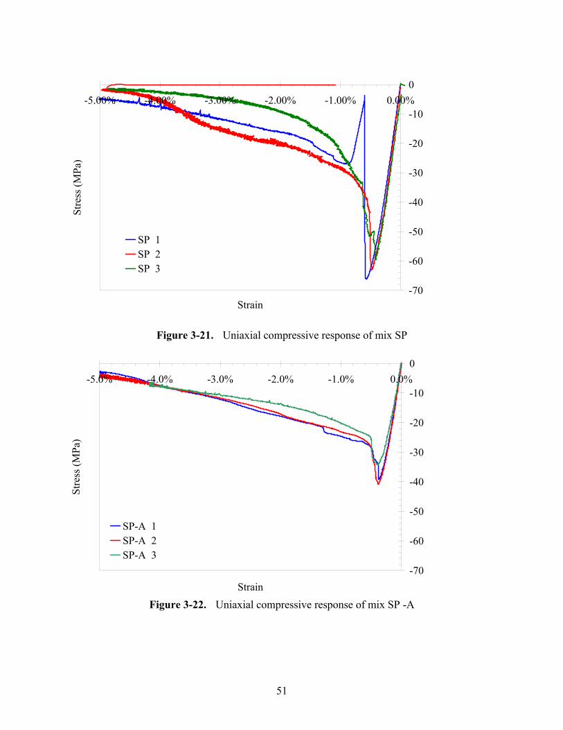
51
Figure 3-21. Uniaxial compressive response of mix SP
Figure 3-22. Uniaxial compressive response of mix SP -A
-70
-60
-50
-40
-30
-20
-10
0-5.0% -4.0% -3.0% -2.0% -1.0% 0.0%
Strain
Stre
ss (M
Pa)
SP-A 1SP-A 2SP-A 3
-70
-60
-50
-40
-30
-20
-10
0-5.00% -4.00% -3.00% -2.00% -1.00% 0.00%
Strain
Stre
ss (M
Pa)
SP 1SP 2SP 3
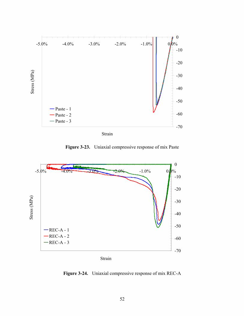
52
Figure 3-23. Uniaxial compressive response of mix Paste
Figure 3-24. Uniaxial compressive response of mix REC-A
-70
-60
-50
-40
-30
-20
-10
0-5.0% -4.0% -3.0% -2.0% -1.0% 0.0%
Strain
Stre
ss (M
Pa)
Paste - 1Paste - 2Paste - 3
-70
-60
-50
-40
-30
-20
-10
0-5.0% -4.0% -3.0% -2.0% -1.0% 0.0%
Strain
Stre
ss (M
Pa)
REC-A - 1REC-A - 2REC-A - 3
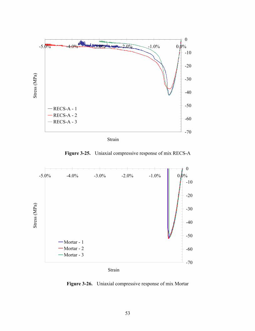
53
Figure 3-25. Uniaxial compressive response of mix RECS-A
Figure 3-26. Uniaxial compressive response of mix Mortar
-70
-60
-50
-40
-30
-20
-10
0-5.0% -4.0% -3.0% -2.0% -1.0% 0.0%
Strain
Stre
ss (M
Pa)
RECS-A - 1RECS-A - 2RECS-A - 3
-70
-60
-50
-40
-30
-20
-10
0-5.0% -4.0% -3.0% -2.0% -1.0% 0.0%
Strain
Stre
ss (M
Pa)
Mortar - 1Mortar - 2Mortar - 3
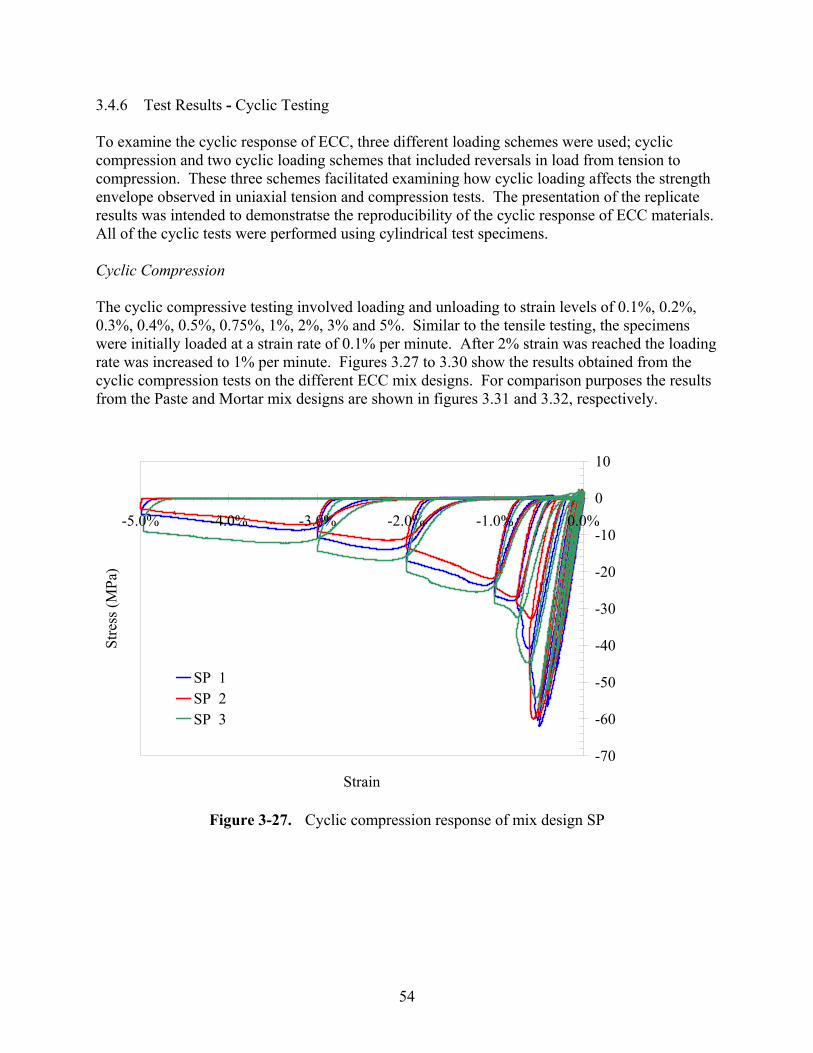
54
3.4.6 Test Results - Cyclic Testing To examine the cyclic response of ECC, three different loading schemes were used; cyclic compression and two cyclic loading schemes that included reversals in load from tension to compression. These three schemes facilitated examining how cyclic loading affects the strength envelope observed in uniaxial tension and compression tests. The presentation of the replicate results was intended to demonstratse the reproducibility of the cyclic response of ECC materials. All of the cyclic tests were performed using cylindrical test specimens. Cyclic Compression The cyclic compressive testing involved loading and unloading to strain levels of 0.1%, 0.2%, 0.3%, 0.4%, 0.5%, 0.75%, 1%, 2%, 3% and 5%. Similar to the tensile testing, the specimens were initially loaded at a strain rate of 0.1% per minute. After 2% strain was reached the loading rate was increased to 1% per minute. Figures 3.27 to 3.30 show the results obtained from the cyclic compression tests on the different ECC mix designs. For comparison purposes the results from the Paste and Mortar mix designs are shown in figures 3.31 and 3.32, respectively.
Figure 3-27. Cyclic compression response of mix design SP
-70
-60
-50
-40
-30
-20
-10
0
10
-5.0% -4.0% -3.0% -2.0% -1.0% 0.0%
Strain
Stre
ss (M
Pa)
SP 1SP 2SP 3
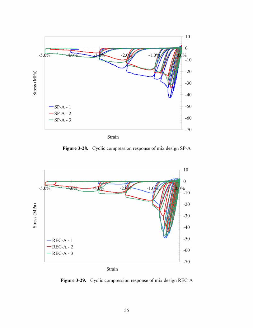
55
Figure 3-28. Cyclic compression response of mix design SP-A
Figure 3-29. Cyclic compression response of mix design REC-A
-70
-60
-50
-40
-30
-20
-10
0
10
-5.0% -4.0% -3.0% -2.0% -1.0% 0.0%
Strain
Stre
ss (M
Pa)
SP-A - 1SP-A - 2SP-A - 3
-70
-60
-50
-40
-30
-20
-10
0
10
-5.0% -4.0% -3.0% -2.0% -1.0% 0.0%
Strain
Stre
ss (M
Pa)
REC-A - 1REC-A - 2REC-A - 3
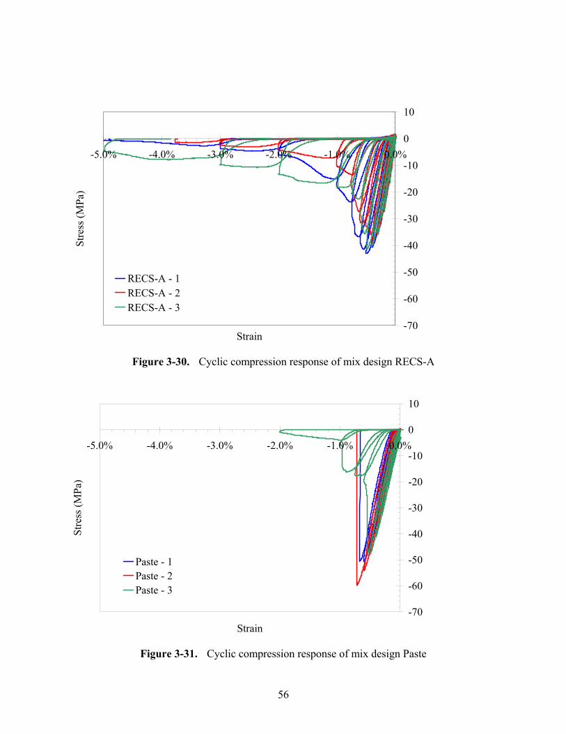
56
Figure 3-30. Cyclic compression response of mix design RECS-A
Figure 3-31. Cyclic compression response of mix design Paste
-70
-60
-50
-40
-30
-20
-10
0
10
-5.0% -4.0% -3.0% -2.0% -1.0% 0.0%
Strain
Stre
ss (M
Pa)
Paste - 1Paste - 2Paste - 3
-70
-60
-50
-40
-30
-20
-10
0
10
-5.0% -4.0% -3.0% -2.0% -1.0% 0.0%
Strain
Stre
ss (M
Pa)
RECS-A - 1RECS-A - 2RECS-A - 3
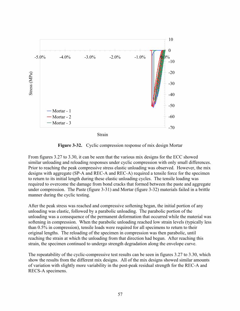
57
Figure 3-32. Cyclic compression response of mix design Mortar
From figures 3.27 to 3.30, it can be seen that the various mix designs for the ECC showed similar unloading and reloading responses under cyclic compression with only small differences. Prior to reaching the peak compressive stress elastic unloading was observed. However, the mix designs with aggregate (SP-A and REC-A and REC-A) required a tensile force for the specimen to return to its initial length during these elastic unloading cycles. The tensile loading was required to overcome the damage from bond cracks that formed between the paste and aggregate under compression. The Paste (figure 3-31) and Mortar (figure 3-32) materials failed in a brittle manner during the cyclic testing. After the peak stress was reached and compressive softening began, the initial portion of any unloading was elastic, followed by a parabolic unloading. The parabolic portion of the unloading was a consequence of the permanent deformation that occurred while the material was softening in compression. When the parabolic unloading reached low strain levels (typically less than 0.5% in compression), tensile loads were required for all specimens to return to their original lengths. The reloading of the specimen in compression was then parabolic, until reaching the strain at which the unloading from that direction had begun. After reaching this strain, the specimen continued to undergo strength degradation along the envelope curve. The repeatability of the cyclic-compressive test results can be seen in figures 3.27 to 3.30, which show the results from the different mix designs. All of the mix designs showed similar amounts of variation with slightly more variability in the post-peak residual strength for the REC-A and RECS-A specimens.
-70
-60
-50
-40
-30
-20
-10
0
10
-5.0% -4.0% -3.0% -2.0% -1.0% 0.0%
Strain
Stre
ss (M
Pa)
Mortar - 1Mortar - 2Mortar - 3
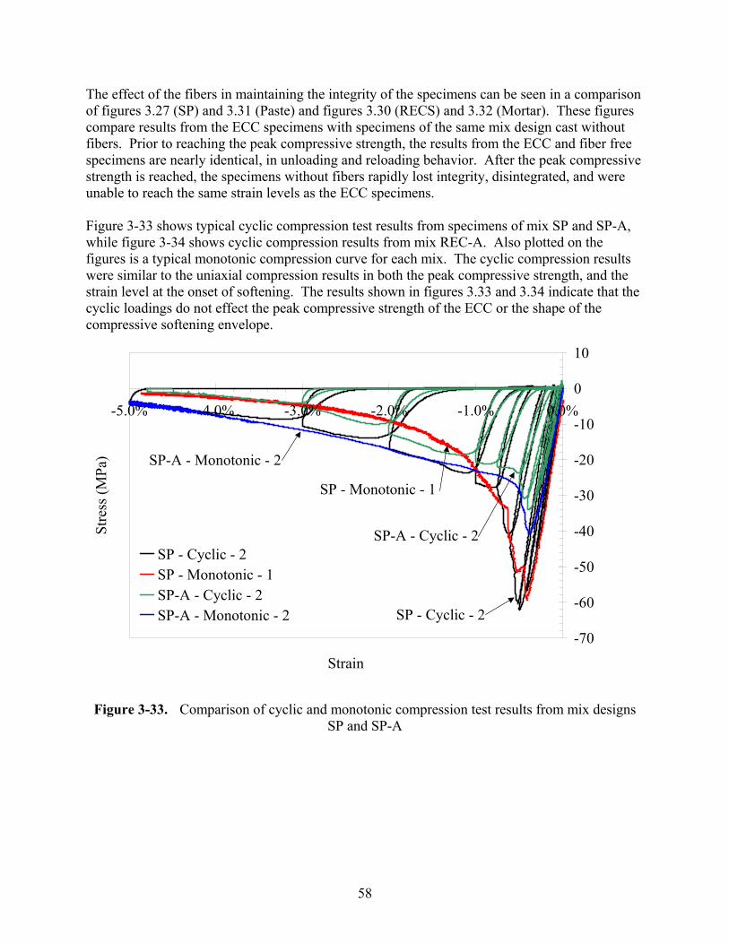
58
The effect of the fibers in maintaining the integrity of the specimens can be seen in a comparison of figures 3.27 (SP) and 3.31 (Paste) and figures 3.30 (RECS) and 3.32 (Mortar). These figures compare results from the ECC specimens with specimens of the same mix design cast without fibers. Prior to reaching the peak compressive strength, the results from the ECC and fiber free specimens are nearly identical, in unloading and reloading behavior. After the peak compressive strength is reached, the specimens without fibers rapidly lost integrity, disintegrated, and were unable to reach the same strain levels as the ECC specimens. Figure 3-33 shows typical cyclic compression test results from specimens of mix SP and SP-A, while figure 3-34 shows cyclic compression results from mix REC-A. Also plotted on the figures is a typical monotonic compression curve for each mix. The cyclic compression results were similar to the uniaxial compression results in both the peak compressive strength, and the strain level at the onset of softening. The results shown in figures 3.33 and 3.34 indicate that the cyclic loadings do not effect the peak compressive strength of the ECC or the shape of the compressive softening envelope.
Figure 3-33. Comparison of cyclic and monotonic compression test results from mix designs
SP and SP-A
-70
-60
-50
-40
-30
-20
-10
0
10
-5.0% -4.0% -3.0% -2.0% -1.0% 0.0%
Strain
Stre
ss (M
Pa)
SP - Cyclic - 2SP - Monotonic - 1SP-A - Cyclic - 2SP-A - Monotonic - 2
SP-A - Monotonic - 2
SP - Monotonic - 1
SP - Cyclic - 2
SP-A - Cyclic - 2
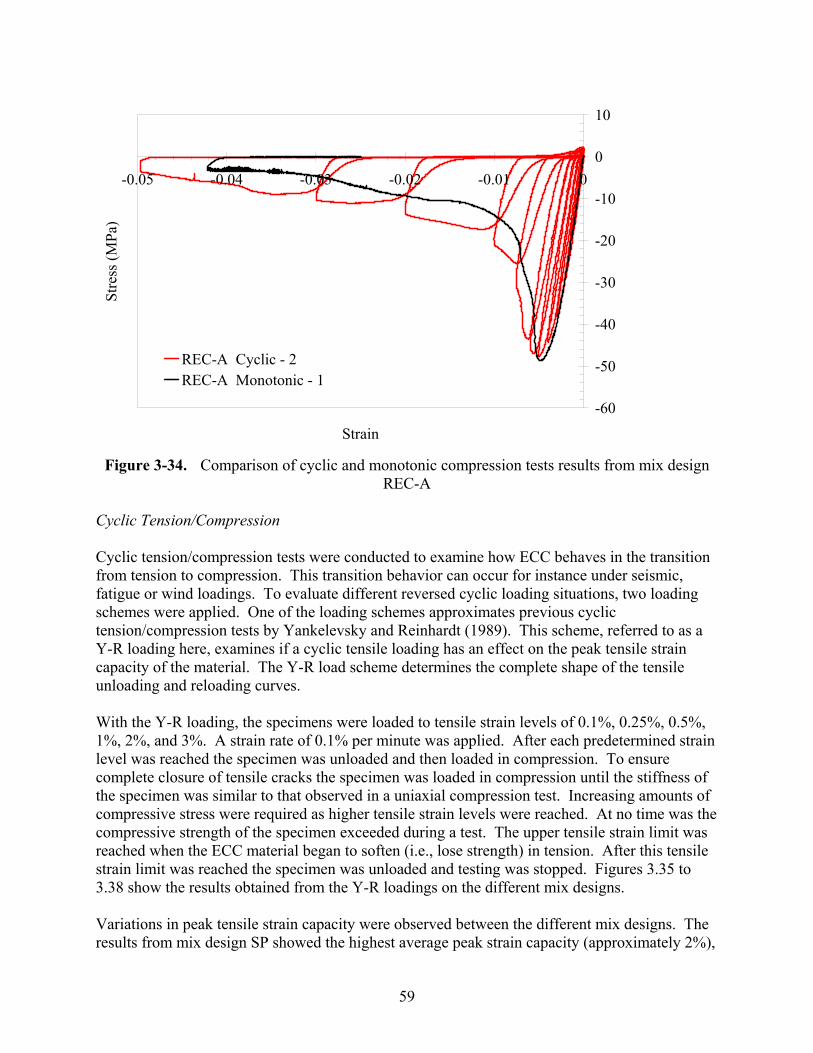
59
Figure 3-34. Comparison of cyclic and monotonic compression tests results from mix design REC-A
Cyclic Tension/Compression Cyclic tension/compression tests were conducted to examine how ECC behaves in the transition from tension to compression. This transition behavior can occur for instance under seismic, fatigue or wind loadings. To evaluate different reversed cyclic loading situations, two loading schemes were applied. One of the loading schemes approximates previous cyclic tension/compression tests by Yankelevsky and Reinhardt (1989). This scheme, referred to as a Y-R loading here, examines if a cyclic tensile loading has an effect on the peak tensile strain capacity of the material. The Y-R load scheme determines the complete shape of the tensile unloading and reloading curves. With the Y-R loading, the specimens were loaded to tensile strain levels of 0.1%, 0.25%, 0.5%, 1%, 2%, and 3%. A strain rate of 0.1% per minute was applied. After each predetermined strain level was reached the specimen was unloaded and then loaded in compression. To ensure complete closure of tensile cracks the specimen was loaded in compression until the stiffness of the specimen was similar to that observed in a uniaxial compression test. Increasing amounts of compressive stress were required as higher tensile strain levels were reached. At no time was the compressive strength of the specimen exceeded during a test. The upper tensile strain limit was reached when the ECC material began to soften (i.e., lose strength) in tension. After this tensile strain limit was reached the specimen was unloaded and testing was stopped. Figures 3.35 to 3.38 show the results obtained from the Y-R loadings on the different mix designs. Variations in peak tensile strain capacity were observed between the different mix designs. The results from mix design SP showed the highest average peak strain capacity (approximately 2%),
-60
-50
-40
-30
-20
-10
0
10
-0.05 -0.04 -0.03 -0.02 -0.01 0
Strain
Stre
ss (M
Pa)
REC-A Cyclic - 2REC-A Monotonic - 1
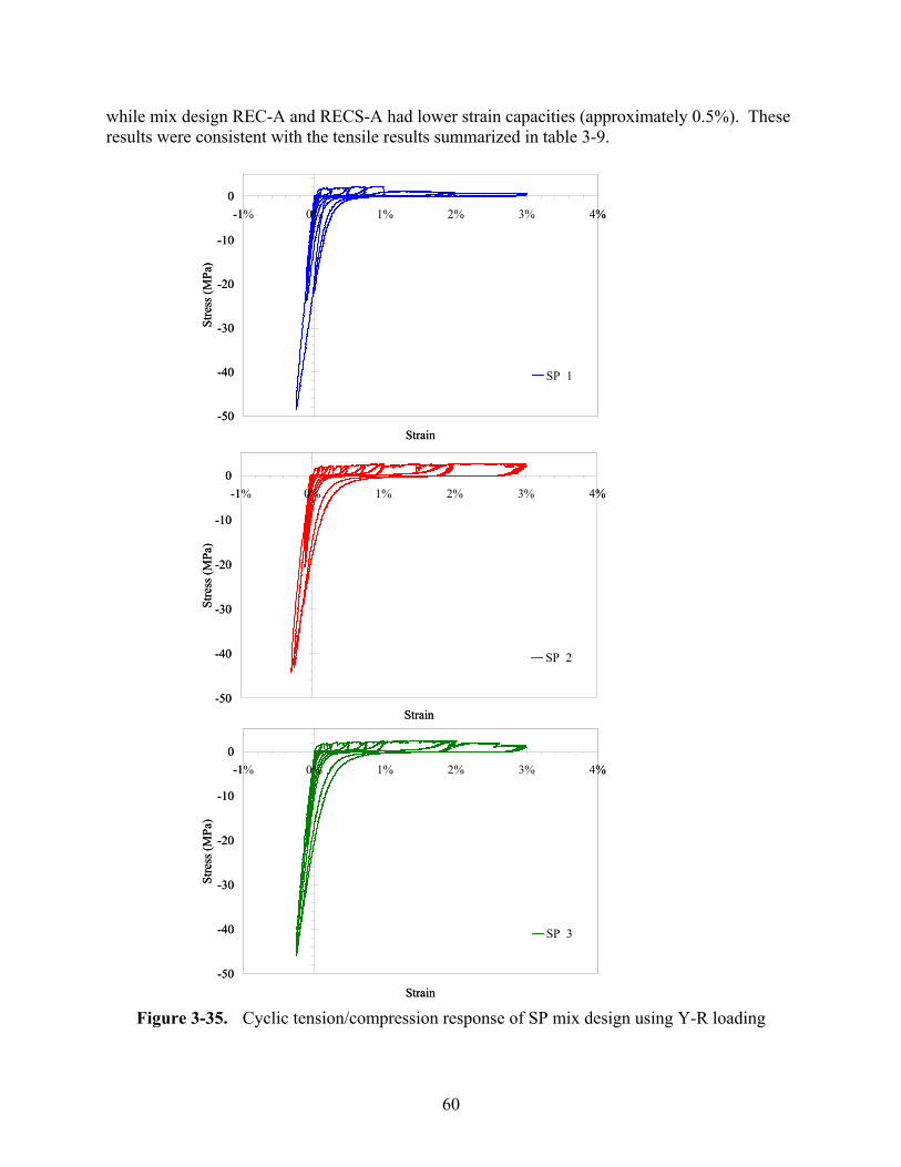
60
while mix design REC-A and RECS-A had lower strain capacities (approximately 0.5%). These results were consistent with the tensile results summarized in table 3-9.
Figure 3-35. Cyclic tension/compression response of SP mix design using Y-R loading
-50
-40
-30
-20
-10
0-1% 0% 1% 2% 3% 4%
Strain
Stre
ss (M
Pa)
SP 1
-50
-40
-30
-20
-10
0-1% 0% 1% 2% 3% 4%
Strain
Stre
ss (M
Pa)
SP 3
-50
-40
-30
-20
-10
0-1% 0% 1% 2% 3% 4%
Strain
Stre
ss (M
Pa)
SP 2
-50
-40
-30
-20
-10
0-1% 0% 1% 2% 3% 4%
Strain
Stre
ss (M
Pa)
SP 1
-50
-40
-30
-20
-10
0-1% 0% 1% 2% 3% 4%
Strain
Stre
ss (M
Pa)
SP 3
-50
-40
-30
-20
-10
0-1% 0% 1% 2% 3% 4%
Strain
Stre
ss (M
Pa)
SP 2
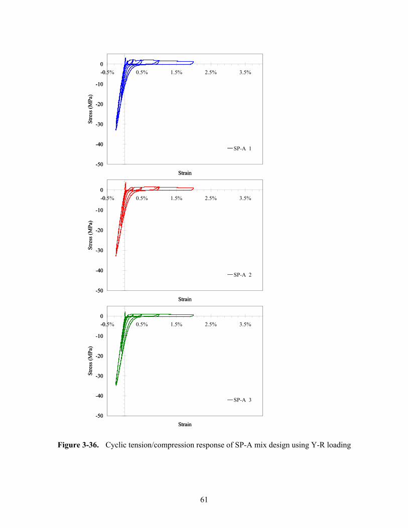
61
Figure 3-36. Cyclic tension/compression response of SP-A mix design using Y-R loading
-50
-40
-30
-20
-10
0-0.5% 0.5% 1.5% 2.5% 3.5%
Strain
Stre
ss (M
Pa)
SP-A 1
-50
-40
-30
-20
-10
0-0.5% 0.5% 1.5% 2.5% 3.5%
Strain
Stre
ss (M
Pa)
SP-A 2
-50
-40
-30
-20
-10
0-0.5% 0.5% 1.5% 2.5% 3.5%
Strain
Stre
ss (M
Pa)
SP-A 3
-50
-40
-30
-20
-10
0-0.5% 0.5% 1.5% 2.5% 3.5%
Strain
Stre
ss (M
Pa)
SP-A 1
-50
-40
-30
-20
-10
0-0.5% 0.5% 1.5% 2.5% 3.5%
Strain
Stre
ss (M
Pa)
SP-A 2
-50
-40
-30
-20
-10
0-0.5% 0.5% 1.5% 2.5% 3.5%
Strain
Stre
ss (M
Pa)
SP-A 3
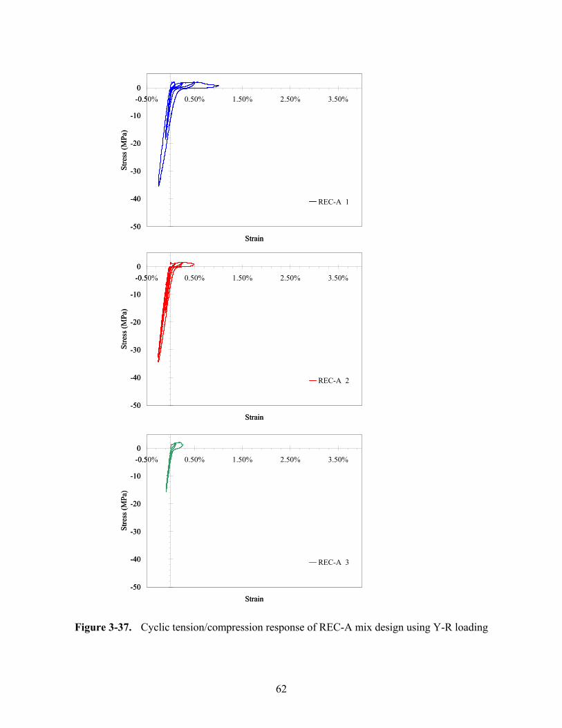
62
Figure 3-37. Cyclic tension/compression response of REC-A mix design using Y-R loading
-50
-40
-30
-20
-10
0-0.50% 0.50% 1.50% 2.50% 3.50%
Strain
Stre
ss (M
Pa)
REC-A 1
-50
-40
-30
-20
-10
0-0.50% 0.50% 1.50% 2.50% 3.50%
Strain
Stre
ss (M
Pa)
REC-A 2
-50
-40
-30
-20
-10
0-0.50% 0.50% 1.50% 2.50% 3.50%
Strain
Stre
ss (M
Pa)
REC-A 3
-50
-40
-30
-20
-10
0-0.50% 0.50% 1.50% 2.50% 3.50%
Strain
Stre
ss (M
Pa)
REC-A 1
-50
-40
-30
-20
-10
0-0.50% 0.50% 1.50% 2.50% 3.50%
Strain
Stre
ss (M
Pa)
REC-A 2
-50
-40
-30
-20
-10
0-0.50% 0.50% 1.50% 2.50% 3.50%
Strain
Stre
ss (M
Pa)
REC-A 3
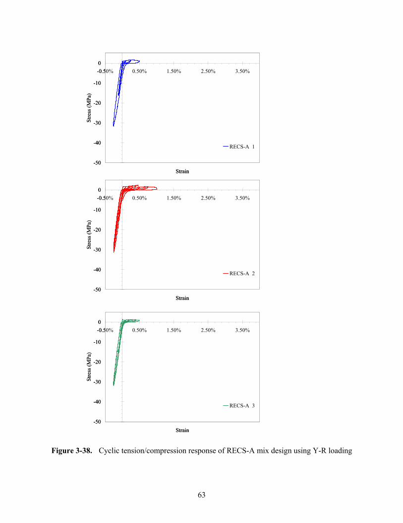
63
Figure 3-38. Cyclic tension/compression response of RECS-A mix design using Y-R loading
-50
-40
-30
-20
-10
0-0.50% 0.50% 1.50% 2.50% 3.50%
Strain
Stre
ss (M
Pa)
RECS-A 1
-50
-40
-30
-20
-10
0-0.50% 0.50% 1.50% 2.50% 3.50%
Strain
Stre
ss (M
Pa)
RECS-A 2
-50
-40
-30
-20
-10
0-0.50% 0.50% 1.50% 2.50% 3.50%
Strain
Stre
ss (M
Pa)
RECS-A 3
-50
-40
-30
-20
-10
0-0.50% 0.50% 1.50% 2.50% 3.50%
Strain
Stre
ss (M
Pa)
RECS-A 1
-50
-40
-30
-20
-10
0-0.50% 0.50% 1.50% 2.50% 3.50%
Strain
Stre
ss (M
Pa)
RECS-A 2
-50
-40
-30
-20
-10
0-0.50% 0.50% 1.50% 2.50% 3.50%
Strain
Stre
ss (M
Pa)
RECS-A 3
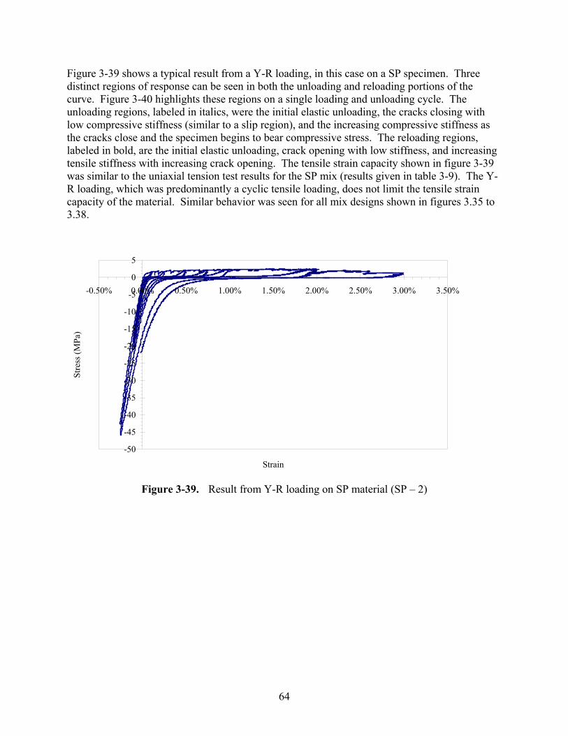
64
Figure 3-39 shows a typical result from a Y-R loading, in this case on a SP specimen. Three distinct regions of response can be seen in both the unloading and reloading portions of the curve. Figure 3-40 highlights these regions on a single loading and unloading cycle. The unloading regions, labeled in italics, were the initial elastic unloading, the cracks closing with low compressive stiffness (similar to a slip region), and the increasing compressive stiffness as the cracks close and the specimen begins to bear compressive stress. The reloading regions, labeled in bold, are the initial elastic unloading, crack opening with low stiffness, and increasing tensile stiffness with increasing crack opening. The tensile strain capacity shown in figure 3-39 was similar to the uniaxial tension test results for the SP mix (results given in table 3-9). The Y-R loading, which was predominantly a cyclic tensile loading, does not limit the tensile strain capacity of the material. Similar behavior was seen for all mix designs shown in figures 3.35 to 3.38.
Figure 3-39. Result from Y-R loading on SP material (SP – 2)
-50
-45
-40
-35
-30
-25
-20
-15
-10
-5
0
5
-0.50% 0.00% 0.50% 1.00% 1.50% 2.00% 2.50% 3.00% 3.50%
Strain
Stre
ss (M
Pa)
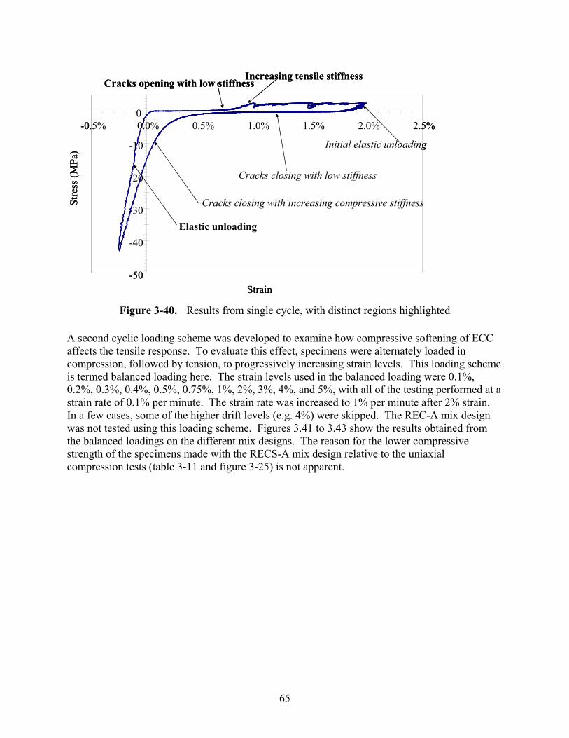
65
Figure 3-40. Results from single cycle, with distinct regions highlighted A second cyclic loading scheme was developed to examine how compressive softening of ECC affects the tensile response. To evaluate this effect, specimens were alternately loaded in compression, followed by tension, to progressively increasing strain levels. This loading scheme is termed balanced loading here. The strain levels used in the balanced loading were 0.1%, 0.2%, 0.3%, 0.4%, 0.5%, 0.75%, 1%, 2%, 3%, 4%, and 5%, with all of the testing performed at a strain rate of 0.1% per minute. The strain rate was increased to 1% per minute after 2% strain. In a few cases, some of the higher drift levels (e.g. 4%) were skipped. The REC-A mix design was not tested using this loading scheme. Figures 3.41 to 3.43 show the results obtained from the balanced loadings on the different mix designs. The reason for the lower compressive strength of the specimens made with the RECS-A mix design relative to the uniaxial compression tests (table 3-11 and figure 3-25) is not apparent.
-50
-40
-30
-20
-10
0-0.5% 0.0% 0.5% 1.0% 1.5% 2.0% 2.5%
Strain
Stre
ss (M
Pa)
Cracks opening with low stiffnessIncreasing tensile stiffness
Cracks closing with low stiffness
Initial elastic unloading
Cracks closing with increasing compressive stiffness
Elastic unloading
-50
-40
-30
-20
-10
0-0.5% 0.0% 0.5% 1.0% 1.5% 2.0% 2.5%
Strain
Stre
ss (M
Pa)
Cracks opening with low stiffnessIncreasing tensile stiffness
Cracks closing with low stiffness
Initial elastic unloading
Cracks closing with increasing compressive stiffness
Elastic unloading
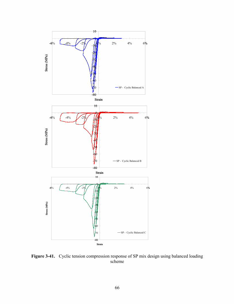
66
Figure 3-41. Cyclic tension compression response of SP mix design using balanced loading
scheme
-80
-70
-60
-50
-40
-30
-20
-10
0
10
-6% -4% -2% 0% 2% 4% 6%
Strain
Stre
ss (M
Pa)
SP - Cyclic Balanced A
-80
-70
-60
-50
-40
-30
-20
-10
0
10
-6% -4% -2% 0% 2% 4% 6%
Strain
Stre
ss (M
Pa)
SP - Cyclic Balanced B
-80
-70
-60
-50
-40
-30
-20
-10
0
10
-6% -4% -2% 0% 2% 4% 6%
Strain
Stre
ss (M
Pa)
SP - Cyclic Balanced C
-80
-70
-60
-50
-40
-30
-20
-10
0
10
-6% -4% -2% 0% 2% 4% 6%
Strain
Stre
ss (M
Pa)
SP - Cyclic Balanced A
-80
-70
-60
-50
-40
-30
-20
-10
0
10
-6% -4% -2% 0% 2% 4% 6%
Strain
Stre
ss (M
Pa)
SP - Cyclic Balanced B
-80
-70
-60
-50
-40
-30
-20
-10
0
10
-6% -4% -2% 0% 2% 4% 6%
Strain
Stre
ss (M
Pa)
SP - Cyclic Balanced C
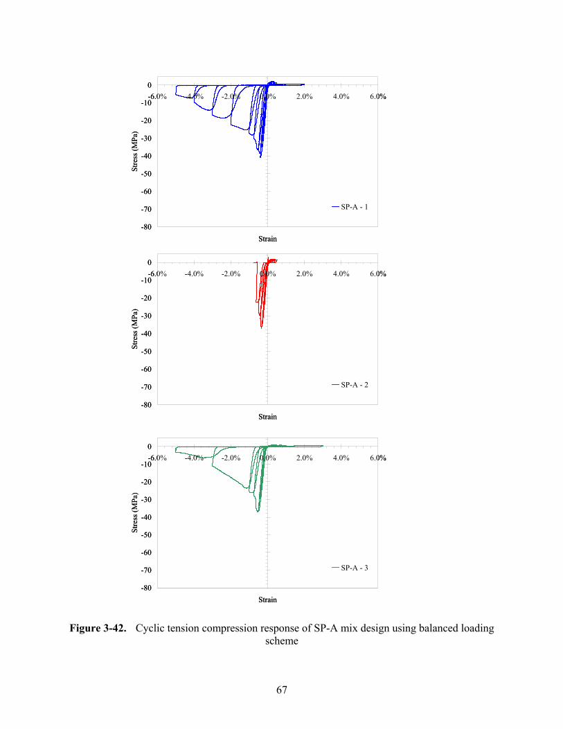
67
Figure 3-42. Cyclic tension compression response of SP-A mix design using balanced loading
scheme
-80
-70
-60
-50
-40
-30
-20
-10
0-6.0% -4.0% -2.0% 0.0% 2.0% 4.0% 6.0%
Strain
Stre
ss (M
Pa)
SP-A - 1
-80
-70
-60
-50
-40
-30
-20
-10
0-6.0% -4.0% -2.0% 0.0% 2.0% 4.0% 6.0%
Strain
Stre
ss (M
Pa)
SP-A - 2
-80
-70
-60
-50
-40
-30
-20
-10
0-6.0% -4.0% -2.0% 0.0% 2.0% 4.0% 6.0%
Strain
Stre
ss (M
Pa)
SP-A - 3
-80
-70
-60
-50
-40
-30
-20
-10
0-6.0% -4.0% -2.0% 0.0% 2.0% 4.0% 6.0%
Strain
Stre
ss (M
Pa)
SP-A - 1
-80
-70
-60
-50
-40
-30
-20
-10
0-6.0% -4.0% -2.0% 0.0% 2.0% 4.0% 6.0%
Strain
Stre
ss (M
Pa)
SP-A - 2
-80
-70
-60
-50
-40
-30
-20
-10
0-6.0% -4.0% -2.0% 0.0% 2.0% 4.0% 6.0%
Strain
Stre
ss (M
Pa)
SP-A - 3
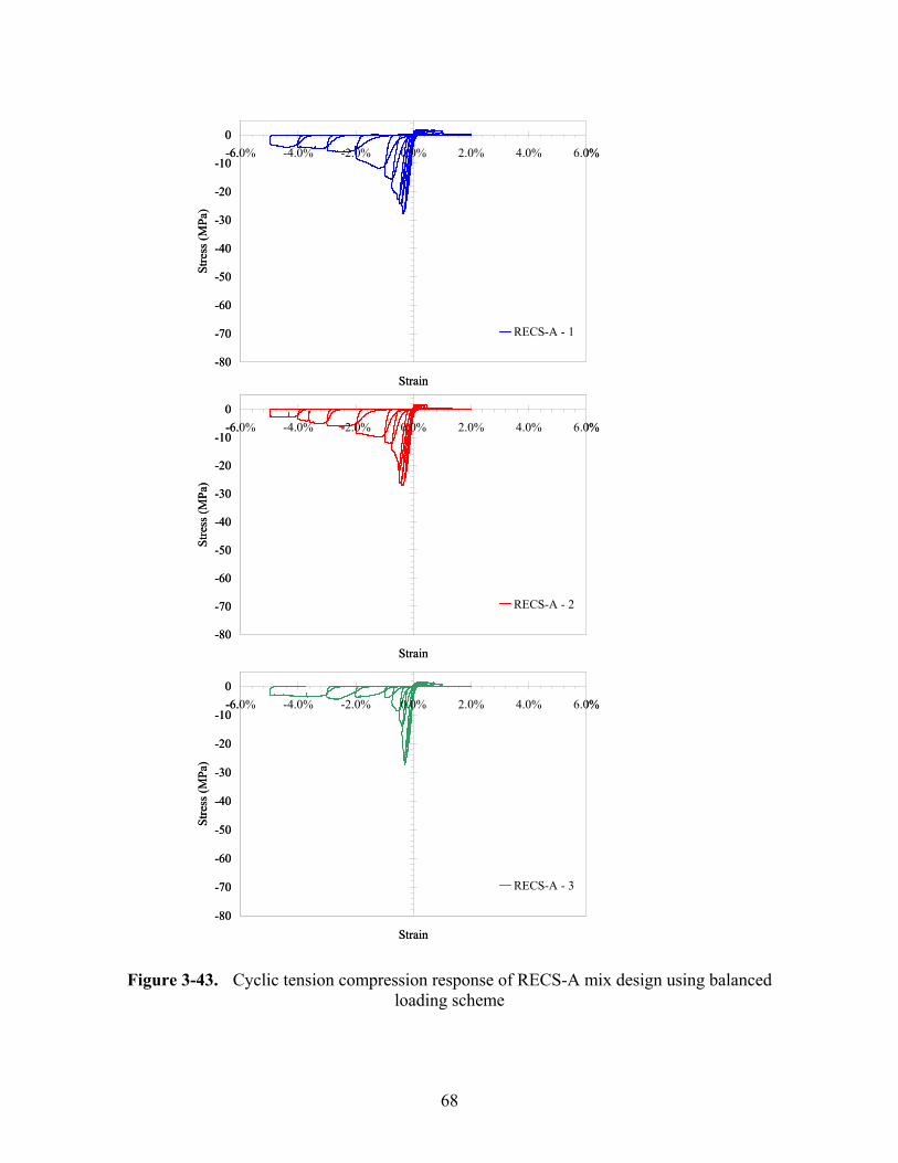
68
Figure 3-43. Cyclic tension compression response of RECS-A mix design using balanced
loading scheme
-80
-70
-60
-50
-40
-30
-20
-10
0-6.0% -4.0% -2.0% 0.0% 2.0% 4.0% 6.0%
Strain
Stre
ss (M
Pa)
RECS-A - 1
-80
-70
-60
-50
-40
-30
-20
-10
0-6.0% -4.0% -2.0% 0.0% 2.0% 4.0% 6.0%
Strain
Stre
ss (M
Pa)
RECS-A - 2
-80
-70
-60
-50
-40
-30
-20
-10
0-6.0% -4.0% -2.0% 0.0% 2.0% 4.0% 6.0%
Strain
Stre
ss (M
Pa)
RECS-A - 3
-80
-70
-60
-50
-40
-30
-20
-10
0-6.0% -4.0% -2.0% 0.0% 2.0% 4.0% 6.0%
Strain
Stre
ss (M
Pa)
RECS-A - 1
-80
-70
-60
-50
-40
-30
-20
-10
0-6.0% -4.0% -2.0% 0.0% 2.0% 4.0% 6.0%
Strain
Stre
ss (M
Pa)
RECS-A - 2
-80
-70
-60
-50
-40
-30
-20
-10
0-6.0% -4.0% -2.0% 0.0% 2.0% 4.0% 6.0%
Strain
Stre
ss (M
Pa)
RECS-A - 3
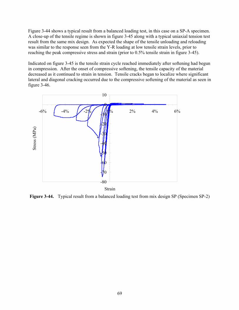
69
Figure 3-44 shows a typical result from a balanced loading test, in this case on a SP-A specimen. A close-up of the tensile regime is shown in figure 3-45 along with a typical uniaxial tension test result from the same mix design. As expected the shape of the tensile unloading and reloading was similar to the response seen from the Y-R loading at low tensile strain levels, prior to reaching the peak compressive stress and strain (prior to 0.5% tensile strain in figure 3-45). Indicated on figure 3-45 is the tensile strain cycle reached immediately after softening had begun in compression. After the onset of compressive softening, the tensile capacity of the material decreased as it continued to strain in tension. Tensile cracks began to localize where significant lateral and diagonal cracking occurred due to the compressive softening of the material as seen in figure 3-46.
Figure 3-44. Typical result from a balanced loading test from mix design SP (Specimen SP-2)
-80
-70
-60
-50
-40
-30
-20
-10
0
10
-6% -4% -2% 0% 2% 4% 6%
Strain
Stre
ss (M
Pa)
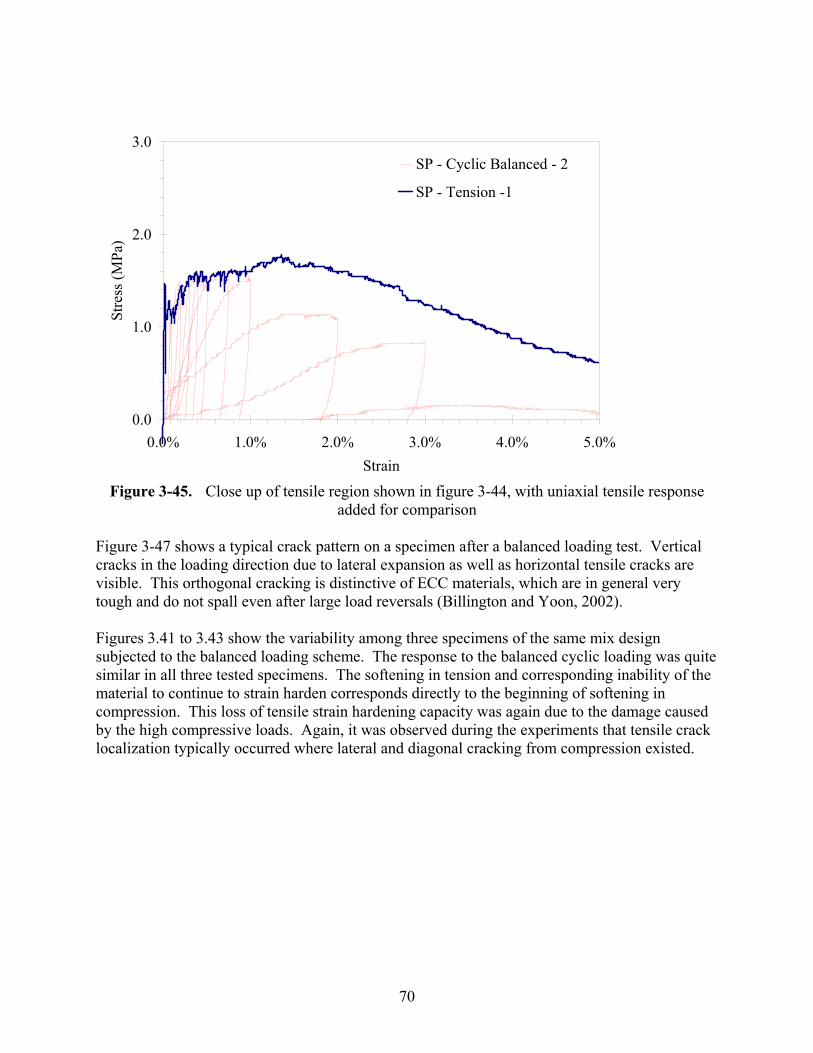
70
Figure 3-45. Close up of tensile region shown in figure 3-44, with uniaxial tensile response added for comparison
Figure 3-47 shows a typical crack pattern on a specimen after a balanced loading test. Vertical cracks in the loading direction due to lateral expansion as well as horizontal tensile cracks are visible. This orthogonal cracking is distinctive of ECC materials, which are in general very tough and do not spall even after large load reversals (Billington and Yoon, 2002). Figures 3.41 to 3.43 show the variability among three specimens of the same mix design subjected to the balanced loading scheme. The response to the balanced cyclic loading was quite similar in all three tested specimens. The softening in tension and corresponding inability of the material to continue to strain harden corresponds directly to the beginning of softening in compression. This loss of tensile strain hardening capacity was again due to the damage caused by the high compressive loads. Again, it was observed during the experiments that tensile crack localization typically occurred where lateral and diagonal cracking from compression existed.
0.0
1.0
2.0
3.0
0.0% 1.0% 2.0% 3.0% 4.0% 5.0%Strain
Stre
ss (M
Pa)
SP - Cyclic Balanced - 2
SP - Tension -1
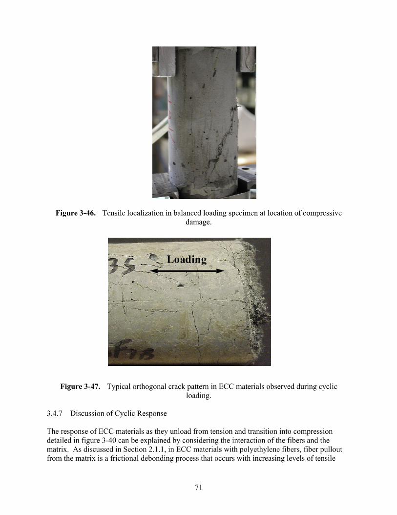
71
Figure 3-46. Tensile localization in balanced loading specimen at location of compressive damage.
Figure 3-47. Typical orthogonal crack pattern in ECC materials observed during cyclic
loading. 3.4.7 Discussion of Cyclic Response The response of ECC materials as they unload from tension and transition into compression detailed in figure 3-40 can be explained by considering the interaction of the fibers and the matrix. As discussed in Section 2.1.1, in ECC materials with polyethylene fibers, fiber pullout from the matrix is a frictional debonding process that occurs with increasing levels of tensile
Loading
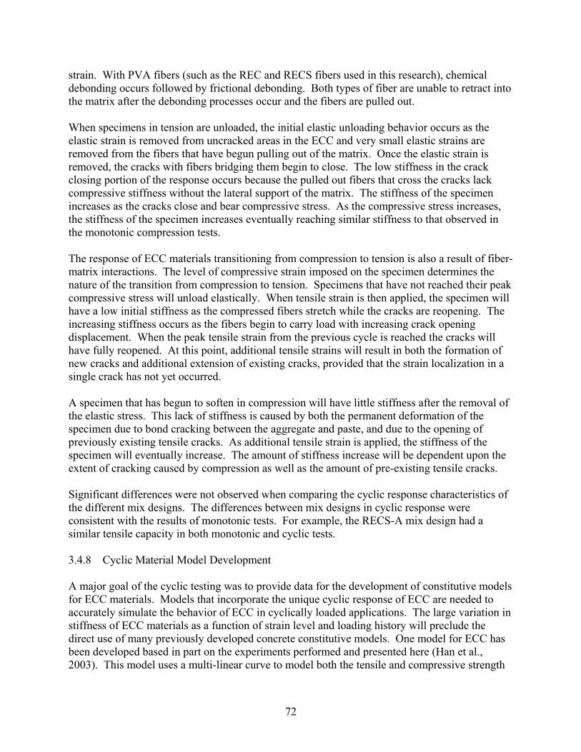
72
strain. With PVA fibers (such as the REC and RECS fibers used in this research), chemical debonding occurs followed by frictional debonding. Both types of fiber are unable to retract into the matrix after the debonding processes occur and the fibers are pulled out. When specimens in tension are unloaded, the initial elastic unloading behavior occurs as the elastic strain is removed from uncracked areas in the ECC and very small elastic strains are removed from the fibers that have begun pulling out of the matrix. Once the elastic strain is removed, the cracks with fibers bridging them begin to close. The low stiffness in the crack closing portion of the response occurs because the pulled out fibers that cross the cracks lack compressive stiffness without the lateral support of the matrix. The stiffness of the specimen increases as the cracks close and bear compressive stress. As the compressive stress increases, the stiffness of the specimen increases eventually reaching similar stiffness to that observed in the monotonic compression tests. The response of ECC materials transitioning from compression to tension is also a result of fiber-matrix interactions. The level of compressive strain imposed on the specimen determines the nature of the transition from compression to tension. Specimens that have not reached their peak compressive stress will unload elastically. When tensile strain is then applied, the specimen will have a low initial stiffness as the compressed fibers stretch while the cracks are reopening. The increasing stiffness occurs as the fibers begin to carry load with increasing crack opening displacement. When the peak tensile strain from the previous cycle is reached the cracks will have fully reopened. At this point, additional tensile strains will result in both the formation of new cracks and additional extension of existing cracks, provided that the strain localization in a single crack has not yet occurred. A specimen that has begun to soften in compression will have little stiffness after the removal of the elastic stress. This lack of stiffness is caused by both the permanent deformation of the specimen due to bond cracking between the aggregate and paste, and due to the opening of previously existing tensile cracks. As additional tensile strain is applied, the stiffness of the specimen will eventually increase. The amount of stiffness increase will be dependent upon the extent of cracking caused by compression as well as the amount of pre-existing tensile cracks. Significant differences were not observed when comparing the cyclic response characteristics of the different mix designs. The differences between mix designs in cyclic response were consistent with the results of monotonic tests. For example, the RECS-A mix design had a similar tensile capacity in both monotonic and cyclic tests. 3.4.8 Cyclic Material Model Development A major goal of the cyclic testing was to provide data for the development of constitutive models for ECC materials. Models that incorporate the unique cyclic response of ECC are needed to accurately simulate the behavior of ECC in cyclically loaded applications. The large variation in stiffness of ECC materials as a function of strain level and loading history will preclude the direct use of many previously developed concrete constitutive models. One model for ECC has been developed based in part on the experiments performed and presented here (Han et al., 2003). This model uses a multi-linear curve to model both the tensile and compressive strength

73
envelopes. The unloading/reloading behavior in compression and in tension before the onset of tensile softening was modeled using power laws. Unloading in the tensile softening regime is assumed to be linear. The model was implemented as a total strain based co-axial model (Feenstra et al., 1998). The cyclic testing indicated that results from monotonic uniaxial tension and compression tests could be used to provide input parameters (e.g. modulus of elasticity, peak stress, peak strain) for an ECC cyclic material model that uses uniaxial stress-strain data provided that the compressive strength of the material is not anticipated to be exceeded. Where the compressive strength is expected to be exceeded, a reduced tensile response would be necessary. 3.4.9 Summary of Cyclic Test Results The response of ECC materials to cyclic uniaxial tensile and compressive loading was evaluated. The ECC materials were observed to have a distinctive loading and unloading response in both tension and compression. The inability of the fibers to rebond/retract into the matrix after pullout produced a low stiffness area in the cyclic stress-strain response. In compression, the behavior of the ECC materials studied here was largely similar to traditional cementitious materials. The experimental results indicated that reversed cyclic tension-compression loading did not limit the tensile strain capacity of ECC materials, provided that the compressive strength of the material was not exceeded. When the compressive strength of the material was exceeded, the tensile strain capacity of the material was reduced. The reduction in tensile stress and strain capacity occurs because tensile cracks localize in areas where compressive damage has begun, as evidenced by lateral expansion cracks. Significant differences were not observed when comparing the cyclic response characteristics of the different mix designs. Key parameters for an ECC material model can be obtained from the results of monotonic uniaxial tension and compression tests (e.g., modulus of elasticity, peak stress, peak strain). The use of values from monotonic tests must take into consideration the reduction in tensile strain capacity that will occur if the peak compressive strength of the material is exceeded. Three specimens of each material were tested in each loading scheme. This amount of testing was performed to examine the reproducibility and variability of the cyclic test results. The results indicated that the cyclic response of the ECC materials was in general quite reproducible, with minor variations between specimens as shown for example in figures 3.41 to 3.43. 3.5 Implications for ECC Applications The primary difference in ECC response from conventional concrete was the tensile and cyclic tensile response. ECC materials under cyclic loading have a large variation in stiffness as a function of the extent of tensile crack opening and whether the material is being unloaded or reloaded.
74
For reverse cyclic load applications where compression softening is not anticipated in the design, the tensile stress and strain capacity is not expected to be limited relative to uniaxial tensile capacities. However if compressive softening is anticipated, tensile capacities will be reduced. This limitation must be considered in the development of ECC applications. Significant differences were observed in the uniaxial tensile response of ECC materials with different specimen geometries. The difference in size of the two geometries studied would, in particular, affect the number and size of initial imperfections, which could alter the material’s strain hardening capacity. Further investigation is needed to understand and predict the performance of ECC materials in applications of varying size and geometry. Additional research is necessary to examine the causes of the observed variations in tensile response due to specimen geometry. Standard test methods that best capture the response of ECC in engineering applications need to be developed. Furthermore, the experimental testing here was conducted at a slow strain rate, with a limited number of testing cycles. To develop practical applications for ECC materials additional testing is needed at higher strain rates to examine the rate sensitivity of ECC materials. Finally, for the use of ECC materials in applications with repeated loadings, additional testing with a higher number of cycles to evaluate fatigue effects is needed. 3.6 Summary The research presented in this section examined the response of small-scale ECC specimens to various and environmental loading conditions. The goals of this portion of the research were to examine the effect of curing and drying conditions, to examine the tensile specimen response of different geometries, to examine the use of new fibers in ECC materials, and to evaluate the cyclic response of ECC materials. Results obtained in this section were used for two different purposes:
1. Provide test data needed to develop full-scale ECC applications 2. Provide test data needed to develop constitutive models for finite element-based
simulations of ECC behavior in structural applications
Results of the curing and drying condition testing indicated that extended wet curing periods (28 days) followed by a drying period of sufficient length to mitigate the effects of differential relative humidity will produce the highest strain capacity in the material. These findings were used to determine optimal conditions for the production of ECC structural components for later testing. The investigation of tensile specimen geometries revealed significant variations in the strain capacity of ECC materials as a function of the specimen geometry. The differences in response can be attributed to several factors including, fiber alignment effects, specimen end conditions, and variations in initial flaw sizes. An understanding of these geometry effects was necessary to predict accurately the response of larger ECC specimens, and to determine the appropriate size and geometry of ECC specimens for quality purposes. The studies here indicate that further
75
investigation is needed to understand and predict the performance of ECC materials in applications of varying size and geometry. A study of the use of different fiber types indicated that the differences in response can be predicted using the micromechanical principles reviewed in Section 2. These results can be used to develop ECC materials with different properties for varying applications. The response of ECC materials to cyclic loadings to fully reversed cyclic loadings (tension-compression) was examined. The response of the material to cyclic loading was found to be dependent upon both the previous loading applied to the specimen and the applied strain. The observed cyclic response was explained by considering the matrix-fiber interactions during loading and unloading. These testing results are to be used to develop seismic retrofit strategies that optimally use the desirable properties of ECC materials. The testing results were also essential for the development of a constitutive model for use in finite element-based simulations.

77
Section 4 Summary and Conclusions
4.0 Summary The research focused on the development of ECC materials for use in seismic retrofit development. Laboratory tests were developed after completion of a literature review. The laboratory testing in the research focused on an examination of properties of the ECC materials as needed for retrofit applications. Uniaxial testing was performed to evaluate the effect of different curing and drying times, and specimen geometries on monotonic tensile results, and the effect of different constituent (fiber and matrix) materials on the monotonic tensile response and compressive response as well as cyclic tension-compression response (“reversed cyclic loading”). The impact of curing and drying periods on the tensile and compressive response of the materials was not previously documented. Furthermore, this research represents one of the first investigations into the response of the ECC materials to reversed cyclic loadings. 4.1 Conclusions The key findings and conclusions from the ECC material evaluation in this research were:
• The tensile strain capacity of the ECC materials was observed to be sensitive to the length of specimen curing and drying times. Greater tensile strain capacity was obtained with increased wet curing periods. However, sufficient drying time after the cessation of wet curing must be provided to minimize the impact of relative humidity gradients on tensile behavior. Short drying periods were observed to limit the tensile strain capacity of the ECC.
• The uniaxial tensile response of ECC specimens made with different fiber types
was observed to be consistent with the micromechanical theory present by Li (1998).
• Tensile specimen geometry was found to have a significant effect on the tensile
strain capacity of ECC materials. The highest tensile strain capacity was obtained from dogbone-shaped geometry specimens. Prismatic and cylindrical specimens resulted in lower tensile strain capacities. The variation in strain capacity is attributed to differences in fiber alignment, specimen thickness and the effect of initial flaws.
• A unique response was observed when the ECC materials were subjected to
reversed cyclic loadings. The stiffness of the material under cyclic loadings varied as a function of the imposed strain, loading direction, and loading history.
• The shape of the cyclic response curve was not affected by fiber type.
78
• During cyclic testing, the onset of compressive softening (exceeding the peak compressive strength) in the ECC was observed to limit the tensile strain capacity of the material.
• Provided the compressive strength of the ECC has not been exceeded, the results
from monotonic tests can be used to define the strength envelope for cyclic tests. 4.2 Recommendations for Future Work The ECC materials investigated here showed a wide range of tensile properties as a function of specimen geometry and constituent materials. Additional testing is required to examine further the effects of specimen geometry on the tensile response of the materials. The testing needs to include methods to examine the distribution of both the fibers and internal flaws in the materials. Concurrent with the examination of fiber and internal flaw distribution; casting methods need to be developed that minimize the impact of fiber and flaw distribution on the tensile performance of the materials. Another area for future research is an examination of the fiber distribution and orientation in the materials, and the development of methods to evaluate the impact of fiber distribution and orientation on the tensile response of the materials. Statistical methods can be used to develop representative samples of the fiber orientation, and interfacial bond strength of the fibers. The material testing performed in the current research was performed at a constant strain rate, which was similar to the strain rate used in previous testing (Li, 1998). To develop a greater understanding into the behavior of ECC material, the uniaxial and cyclic testing described in Section 3 should be repeated at different strain rates. Such testing would provide insight into the behavior of the ECC in structural applications where higher strain rates are expected, such as for seismic design or impact and blast loading.
79
Section 5
References
1. Li, V., (1998a) “Engineered Cementitious Composites – Tailored Composites Through Micromechanical Modeling,” in Fiber Reinforced Concrete: Present and the Future edited by N. Banthia, A. Bentur and A. Muft, Canadian Society for Civil Engineering, Montreal, pp. 64-97, 1998.
2. Li, V., and Leung, C., (1992) “Steady-State and Multiple Cracking of Short Random
Fiber Composites,” Journal of Engineering Mechanics, Vol. 118, No. 11, pp. 2246-2264.
3. MCEER, (2000) Strategic Plan 2000, http://mceer.buffalo.edu/aboutMCEER/strategicPlan/
4. OSHPD, (1995) “The Northridge Earthquake – A Report to the Hospital Safety Board on
the Performance of Hospital,” Prepared by Office of Statewide Health Planning and Development, Facilities Development Division, 63 pp.
5. Anderson, T.L. (1995) “Fracture Mechanics: Fundamentals and Applications,” CRC
Press.
6. Balaguru, P., and Shah, S.P., (1992) “Fiber reinforced cement composites,” McGraw-Hill, New York, NY., 530 pp.
7. Billington, S.L., and Rouse, J.M. (2003), “Time-dependent response of highly ductile
fiber-reinforced cement-based composites,” Proceedings 7th Symposium on Brittle Matrix Composites,” ZTUTRK RSI and Woodhead Publ., Warsaw, October.
8. Curtin, W. (1991a) “Theory of mechanical properties of ceramic-matrix composites,”
Journal of American Ceramics Society, No. 74, Vol. 11, pp. 2837-2845.
9. Curtin, W. (1991b) “Fiber pull-out and strain localization in ceramic matrix composites,” Journal of Mechanics and Physics of Solids, Vol. 41, No. 1, pp. 35-53.
10. Fukuyama, H., Masuzuki, Y., Nakano, K., and Sato, Y., (1999) “Structural performance
of beam elements with PVA-ECC” High Performance Fiber Reinforced Composites (HPFRCC-3), Reinhardt, H.W. and Naaman, A., (eds.), RILEM, pp. 531-541.
11. Fukuyama, H., Suwada, H., and Ilseung, Y., (2002) “HPFRCC damper for structural
control,” Proceedings of the JCI International Workshop on Ductile Fiber Reinforced Cementitious Composites (DFRCC) – Application and Evaluation, October, 2002, pp. 219-228.
12. Fischer, G., and Li, V.C. (2000) “Structural composites with ECC,” Proceedings of the
ASCCS-6, Edited by Y. Xiao, and S.A. Mahin, USC, pp. 1001-1008.
80
13. Fischer, G. and Li, V. (2002) “Influence of matrix ductility on tension-stiffening
behavior of steel reinforced engineered cementitious composites (ECC),” ACI Structures Journal, Vol. 99, No. 1, pp.104-111.
14. Fischer, G., and Li, V.C., (2002) “Intrinsic response control of moment resisting frames
utilizing advanced composite materials and structural elements,” ACI Structures Journal, Vol. 100, No. 2, pp.166-177.
15. Homrich, J., and Naaman, A.E., (1987) “Stress-strain properties of SIFCON in
compression,” Fiber Reinforced Concrete Properties and Applications, SP-105, American Concrete Institute, Detriot, MI., pp. 283-304.
16. Han, T.S., Feenstra, P.H., and Billington, S.L., (2003) “Simulation of Highly Ductile
Fiber-Reinforced Cement-based Composites,” ACI Structures Journal, Vol. 101, No. 6, pp. 749-757.
17. Horii, H., Kabele, P., Takeuchi, S., Li, V.C., Matsuoka, S., Kanda, T., (1998) “On the
prediction method for the structural performance of repaired/retrofitted structures” Fracture Mechanics in Concrete Structures: Proceedings FRAMCOS-3. Volume III p. 1739-1750.
18. JCI, (2002), “Proceedings of the JCI International Workshop on Ductile Fiber
Reinforced Cementitious Composites (DFRCC),” Japan Concrete Institute, October, 298 pp.
19. Kabele, P., (2001) “Assessment of Structural Performance of Engineered Cementitious
Composites by Computer Simulation,” CTU Reports No. 4, 2001, Volume 5, Czech Technical University, Prague.
20. Kabele, P., Takeuchi, S., Inaba, K., and Horii, H., (1999) “Performance of engineered
cementitious composites in repair and retrofit: analytical estimates,” High Performance Fiber Reinforced Composites (HPFRCC 3), Edited by H.W. Reinhardt, and A. Namaan, Rilem, pp. 617-627.
21. Kanda, T., Watanbe, S., and Li. V.C., (1998) “Application of pseudo strain hardening
cementitious composites to shear resistant structural elements,” Fracture mechanics in concrete structures: Proceedings of Framcos-3, Edited by H. Mihashi and K. Rokugo. Volume III, pp. 1477-1490.
22. Kesner, K.E., Billington, S.L. and Douglas, K.S., “Cyclic Response of Highly Ductile
Fiber-Reinforced Cement-Based Composites,” ACI Materials Journal, September-October 2003, Vol. 100, No. 5, pp. 381-390.
81
23. Krstulovic-Opara, N., and Malak, S. (1997) “Micromechanical tensile behavior of slurry infiltrated continuous-fiber-mat reinforced concrete (SIMCON),” ACI Materials Journal, V. 94, No. 5, Sept.-Oct. 1997, pp. 373-384.
24. Li, V.C., (1998b) “Repair and retrofit with engineered cementitious composites,”
Fracture Mechanics of Concrete Structures Proceedings FRAMCOS-3, AEDIFICATIO Publishers, D-79104 Freiburg, Germany, pp. 1715-1726.
25. Li, V.C., (2002) “Reflections on the research and development of engineered
cementitious composites (ECC),” Proceedings of the JCI International Workshop on Ductile Fiber Reinforced Cementitious Composites (DFRCC) – Application and Evaluation, October, 2002, pp. 1-21.
26. Li, V.C., Wang, S., and Wu, C., (2001) “Tensile strain-hardening behavior of polyvinyl
alcohol engineered cementitious composite (PVA-ECC),” ACI Materials Journal, Vol. 98, No. 6, pp. 483-492.
27. Li, V.C., Wu, C., Wang, S., Ogawa, A., and Saito, T., (2002) “Interface tailoring for
strain-hardening PVA-ECC,” ACI Materials Journal, Vol. 99, No. 5, pp. 463-472.
28. Li, V.C., Wu, H.C., and Chan, Y.W., (1995) “Effect of plasma treatment of polyethylene fibers on interface and cementitious composite properties,” Journal of the American Ceramic Society, Vol. 79, No. 3, pp. 700-704.
29. Li, V.C., Mishra, D., and Wu, H., (1995) “Matrix design for pseudo-strain hardening
fiber reinforced cementitious composites,” RILEM Materials and Structures, 28. 586-595.
30. Li, Z.F., and Netravali, A.N., (1992) “Surface modification of UHSPE fibers through
allylamine plasma deposition. II. Effect on fiber and fiber/epoxy interface,” Journal of Applied Polymer Science, Vol. 44, pp. 333-346.
31. Li, V.C., Wang, Y. and Backer, S., (1990) "Effect of inclining angle, bundling, and
surface treatment on synthetic fiber pull-out from a cement matrix", Journal of Composites, Vol. 21, 2, pp. 132-140.
32. Lim, Y.M., and Li. V.C., (1998) “Characterization of interface fracture behavior in
repaired concrete infrastructures,” Fracture mechanics in concrete structures: Proceedings of Framcos-3, Edited by H. Mihashi and K. Rokugo. Volume III, pp. 1817-1828.
33. MacGregor, J.G.(1992), “Reinforced Concrete: Mechanics and Design,”, Prentice Hall,
Englewood Cliffs, NJ., 848 pp.
82
34. Maleej, M., and Li., V.C., (1995) “Introduction of strain hardening engineered cementitious composites in design of reinforced concrete flexural members for improved durability,” ACI Structural Journal, Vol. 92, No. 2, pp. 167-176.
35. Marshall, D., Cox, B., and Evans, A., (1985) “The mechanics of matrix cracking in
brittle-matrix composites”, Acta Metallographa Vol. 33, No. 11, pp. 2013-2021.
36. Mehta, P. (1986) “Concrete Structures, Properties and Materials,” Prentice Hall Inc., Englewood Cliffs, NJ, 450 pp.
37. Majumdar, A.J., (1970) “Glass fibre reinforced cement and gypsum products,” Proc.
Roy. Soc. Lond. A. 319, pp. 69-78.
38. Parra-Montesinos, G., and Wight, J., (2000) “Seismic response of exterior RC column to steel connections,” Journal of Structural Engineering, Vol. 126, No. 10, pp. 1113-1121.
39. Phoenix, S.L., and Raj, R., (1992) “Scalings in fracture probabilities for a brittle matrix
fiber composite,” Acat metallographa materials, Vol. 40, No. 11, pp. 2813-2828
40. Redon, C., Li, V.C., Wu, C., Hoshiro, H., Saito, T., and Ogawa, A., (2001) “Measuring and Modifying Interface Properties of PVA Fibers in ECC Matrix,” ASCE J. Materials in Civil Engrg., Vol. 13, No. 6, pp. 399-406.
41. Rossi, P., (1997) “High performance multimodal fiber reinforced cement composites
(HPMFRCC): The LCPC experience,” ACI Materials Journal, Vol. 94, No. 6, pp. 478-483.
42. Rouse, J.M., (2003) “Use of DFRCC in unbonded post-tensioned bridge columns,” Ph.D.
Dissertation, Cornell University, Ithaca, NY, in preparation.
43. Soubra, K., Wight, J., and Naaman, A.E., (1991) “Fiber reinforced concrete joints for precast construction in seismic areas,” ACI Structures Journal, Vol. 88, No. 2, pp. 214-221.
44. Xia, Z., and Naaman, A., (2002) “Behavior and modeling of infill fiber-reinforced
concrete damper element for steel-concrete shear wall,” ACI Structural Journal, V. 99, No. 6, pp. 727-739.
45. Yoon, J.K., (2002) “Experimental and numerical studies of precast unbonded post-
tensioned bridge columns with engineered cementitious composites,” Master’s Thesis, Cornell University, Ithaca, NY, 167 pp.
46. ASTM C39, (2002) “Standard Test Method for Compressive Strength of Cylindrical
Concrete Specimens,” American Society for Testing and Materials, 2002.
47. Billington, S.L., and Kesner, K.E., (2001) “Development of Ductile Cement-based Composites for Seismic Strengthening and Retrofit,” in Proceedings for the 2nd
83
International Conference on Engineering Materials, Sponsored by JSCE & CSCE, San Jose, CA.
48. Billington, S.L. and Yoon, J.K. (2004) “Cyclic Response of Precast Concrete Bridge
Columns with Ductile Fiber-Reinforced Concrete,” ASCE J. Bridge Engineering, in press.
49. CEB, (1996) “State of the Art Report RC Elements Under Cyclic Loading,” Thomas
Telford Publications, London, Eng., 190 pp.
50. Feenstra, P.H., Rots, J.G., Arnesen, A., Teigen, J.G., and K.V. Hoiseth., (1998) “A 3D consistitutive model for concrete based on a co-rotational concept,” Computational Modeling of Concrete Structures: Proceedings of the Euro-C 1998 Conference on Computation Modelling of Concrete Structures, R. DeBorst, N. Bicanic, H. Mang, and G. Meschke (eds.), Badgastein, 31 March – 3 April 1998. Rotterdam: Balkema.
51. Han, T.S., Feenstra, P.H., and Billington, S.L., (2002) “Simulation of Highly Ductile
Fiber-Reinforced Cement-based Composites,” ACI Structures Journal, Accepted for publication, November.
52. Hannant, D.J., (1978) Fibre Cements and Fibre Concretes, John Wiley & Sons,
Chicester, NY, 219 pp.
53. http://www.u-s-silica.com/prod_info/PDS/Ottawa/ottawaFs2002.PDF
54. Kanda, T., and Li, V.C., (1999) “New Micromechanics Design Theory for Pseudostrain Hardening Cementitious Composite,” ASCE J. of Engineering Mechanics, Vol. 125, No. 4, pp. 373-381.
55. Karsan, I.D., and Jirsa, J.O., (1969) “Behavior of Concrete under Compressive
Loadings,” ASCE Journal of the Structures Division, Vol. 95, ST12, pp. 2543-2563.
56. Kelly, A. (1972) “Reinforcement of Structural Materials by Long Strong Fibers,” Metallurgical Transactions, Vol. 3, No. 9, pp. 2313-2325.
57. Kesner, K. E. and Billington, S. L. (2001). Investigation of ductile cement based
composites for seismic strengthening and retrofit. In R. de Borst, J. Mazars, G. Pijaudier-Cabot, and J. van Mier (Eds.), Fracture Mechanics of Concrete Structures, pp. 65-72. Proceedings of the Fourth International Conference on Fracture Mechanics of Concrete and Concrete Structures.
58. Kesner, K.E., and Billington, S.L. (2002) “Ductile Cement-Based Infills for Seismic
Retrofit,” Proceedings of the 7th National Conference on Earthquake Engineering, Boston. Proceedings on CD-ROM.
59. Kuraray (2002) Communication with Prof. Sarah L. Billington, Cornell University
84
60. Li, V.C., Wang, S., and Wu, C. (2001) “Tensile Strain-Hardening Behavior of Polyvinyl
Alcohol Engineered Cementitious Composite (PVA-ECC),” ACI Materials Journal, Vol. 98. No. 6, pp. 483-492.
61. Maher, A., and Darwin, D., (1982) “Mortar Constituent of Concrete in Compression,”
Journal of the American Concrete Institute, Vol. 70, No. 2, pp. 100-109.
62. Marshall, D.B., and Cox, B.N. (1988) “A J-integral Method for Calculating Steady-State Matrix Cracking Stresses in Composites,” Mechanics of Materials, Vol. 7, pp. 127-133.
63. Otter, D.E., and Naaman, A., (1988) “Properties of Steel Fiber Reinforced Concrete
under Cyclic Loading,” ACI Materials Journal, Vol. 85, No. 4, pp. 254-261.
64. Poston, R.W., Kesner, K.E., Emmons, P.H., and Vaysburd, A.M., (1998) “Performance for Concrete Repair Materials, Phase II Laboratory Results,” Technical Report REMR-CS-57, U.S. Army Engineer Waterways Experiment Station, Vicksburg, MS, 299 pp.
65. Redon, C., Li, V.C., Wu, C., Hoshiro, H., Saito, T., and Ogawa, A., (2001) “Measuring
and Modifying Interface Properties of PVA Fibers in ECC Matrix,” ASCE J. Materials in Civil Engrg., V. 13, No. 6, pp. 399-406.
66. Sato, Y., Fukuyama, H., and Suwada, H., (2001) “A Proposal of Tension-Compression
Cyclic Loading Test Method for Ductile Cementitious Composite Material, Journal of Structural and Construction Engineering,” Architectural Institute of Japan, No. 539, pp. 7-12 (in Japanese).
67. Sinha, B.P., Gerstle, K.H., and Tulin, L.G., (1964) “Stress Strain Relations for Concrete
under Cyclic Loading,” Journal of the American Concrete Institute, Vol. 61, No. 2, pp. 195-211.
68. Spooner, D.C. (1972) “The Stress-Strain Relationship for Hardened Cement Pastes in
Compression,” Magazine of Concrete Research (London), Vol. 24, No. 79, pp. 85-92.
69. Tay, H.B., (2001) “Interfacial Bond Strength in Engineered Cementitious Composites with Different Polyethylene Fiber Types,” Undergraduate Research Report, Department of Civil and Environmental Engineering, Cornell University, May 2001.
70. van Mier, J.G., (1997) Fracture Processes of Concrete, CRC Press, Boca Raton, FL, 448
pp.
71. van Vliet, M.R., (2000) “Size Effect in Tensile Fracture of Concrete and Rock,” Ph.D. Dissertation, Delft University of Technology, The Netherlands, 192 pp.
85
72. Yankelevsky, D.Z., and Reinhardt, H.W., (1987) “Model for Cyclic Compressive Behavior of Concrete,” ASCE Journal of Structural Engineering, Vol. 113, No. 2, pp. 228-240.
73. Yankelevsky, D.Z., and Reinhardt, H.W., (1989) “Uniaxial Behavior of Concrete in
Cyclic Tension,” ASCE Journal of Structural Engineering, Vol. 115, No. 9, pp. 166-182.
74. Zheng, W., Kwan, A.H., and Lee, P.K., (2001) “Direct Tension Test of Concrete,” ACI Materials Journal, Vol. 98, No. 1, pp. 63-71.

Formerly the National Center for Earthquake Engineering Research
87
Multidisciplinary Center for Earthquake Engineering Research List of Technical Reports
The Multidisciplinary Center for Earthquake Engineering Research (MCEER) publishes technical reports on a variety of subjects related to earthquake engineering written by authors funded through MCEER. These reports are available from both MCEER Publications and the National Technical Information Service (NTIS). Requests for reports should be directed to MCEER Publications, Multidisciplinary Center for Earthquake Engineering Research, State University of New York at Buffalo, Red Jacket Quadrangle, Buffalo, New York 14261. Reports can also be requested through NTIS, 5285 Port Royal Road, Springfield, Virginia 22161. NTIS accession numbers are shown in parenthesis, if available. NCEER-87-0001 "First-Year Program in Research, Education and Technology Transfer," 3/5/87, (PB88-134275, A04, MF-
A01). NCEER-87-0002 "Experimental Evaluation of Instantaneous Optimal Algorithms for Structural Control," by R.C. Lin, T.T.
Soong and A.M. Reinhorn, 4/20/87, (PB88-134341, A04, MF-A01). NCEER-87-0003 "Experimentation Using the Earthquake Simulation Facilities at University at Buffalo," by A.M. Reinhorn
and R.L. Ketter, to be published. NCEER-87-0004 "The System Characteristics and Performance of a Shaking Table," by J.S. Hwang, K.C. Chang and G.C.
Lee, 6/1/87, (PB88-134259, A03, MF-A01). This report is available only through NTIS (see address given above).
NCEER-87-0005 "A Finite Element Formulation for Nonlinear Viscoplastic Material Using a Q Model," by O. Gyebi and G.
Dasgupta, 11/2/87, (PB88-213764, A08, MF-A01). NCEER-87-0006 "Symbolic Manipulation Program (SMP) - Algebraic Codes for Two and Three Dimensional Finite Element
Formulations," by X. Lee and G. Dasgupta, 11/9/87, (PB88-218522, A05, MF-A01). NCEER-87-0007 "Instantaneous Optimal Control Laws for Tall Buildings Under Seismic Excitations," by J.N. Yang, A.
Akbarpour and P. Ghaemmaghami, 6/10/87, (PB88-134333, A06, MF-A01). This report is only available through NTIS (see address given above).
NCEER-87-0008 "IDARC: Inelastic Damage Analysis of Reinforced Concrete Frame - Shear-Wall Structures," by Y.J. Park,
A.M. Reinhorn and S.K. Kunnath, 7/20/87, (PB88-134325, A09, MF-A01). This report is only available through NTIS (see address given above).
NCEER-87-0009 "Liquefaction Potential for New York State: A Preliminary Report on Sites in Manhattan and Buffalo," by
M. Budhu, V. Vijayakumar, R.F. Giese and L. Baumgras, 8/31/87, (PB88-163704, A03, MF-A01). This report is available only through NTIS (see address given above).
NCEER-87-0010 "Vertical and Torsional Vibration of Foundations in Inhomogeneous Media," by A.S. Veletsos and K.W.
Dotson, 6/1/87, (PB88-134291, A03, MF-A01). This report is only available through NTIS (see address given above).
NCEER-87-0011 "Seismic Probabilistic Risk Assessment and Seismic Margins Studies for Nuclear Power Plants," by Howard
H.M. Hwang, 6/15/87, (PB88-134267, A03, MF-A01). This report is only available through NTIS (see address given above).
NCEER-87-0012 "Parametric Studies of Frequency Response of Secondary Systems Under Ground-Acceleration Excitations,"
by Y. Yong and Y.K. Lin, 6/10/87, (PB88-134309, A03, MF-A01). This report is only available through NTIS (see address given above).
NCEER-87-0013 "Frequency Response of Secondary Systems Under Seismic Excitation," by J.A. HoLung, J. Cai and Y.K.
Lin, 7/31/87, (PB88-134317, A05, MF-A01). This report is only available through NTIS (see address given above).
NCEER-87-0014 "Modelling Earthquake Ground Motions in Seismically Active Regions Using Parametric Time Series
Methods," by G.W. Ellis and A.S. Cakmak, 8/25/87, (PB88-134283, A08, MF-A01). This report is only available through NTIS (see address given above).
Formerly the National Center for Earthquake Engineering Research
88
NCEER-87-0015 "Detection and Assessment of Seismic Structural Damage," by E. DiPasquale and A.S. Cakmak, 8/25/87,
(PB88-163712, A05, MF-A01). This report is only available through NTIS (see address given above). NCEER-87-0016 "Pipeline Experiment at Parkfield, California," by J. Isenberg and E. Richardson, 9/15/87, (PB88-163720,
A03, MF-A01). This report is available only through NTIS (see address given above). NCEER-87-0017 "Digital Simulation of Seismic Ground Motion," by M. Shinozuka, G. Deodatis and T. Harada, 8/31/87,
(PB88-155197, A04, MF-A01). This report is available only through NTIS (see address given above). NCEER-87-0018 "Practical Considerations for Structural Control: System Uncertainty, System Time Delay and Truncation of
Small Control Forces," J.N. Yang and A. Akbarpour, 8/10/87, (PB88-163738, A08, MF-A01). This report is only available through NTIS (see address given above).
NCEER-87-0019 "Modal Analysis of Nonclassically Damped Structural Systems Using Canonical Transformation," by J.N.
Yang, S. Sarkani and F.X. Long, 9/27/87, (PB88-187851, A04, MF-A01). NCEER-87-0020 "A Nonstationary Solution in Random Vibration Theory," by J.R. Red-Horse and P.D. Spanos, 11/3/87,
(PB88-163746, A03, MF-A01). NCEER-87-0021 "Horizontal Impedances for Radially Inhomogeneous Viscoelastic Soil Layers," by A.S. Veletsos and K.W.
Dotson, 10/15/87, (PB88-150859, A04, MF-A01). NCEER-87-0022 "Seismic Damage Assessment of Reinforced Concrete Members," by Y.S. Chung, C. Meyer and M.
Shinozuka, 10/9/87, (PB88-150867, A05, MF-A01). This report is available only through NTIS (see address given above).
NCEER-87-0023 "Active Structural Control in Civil Engineering," by T.T. Soong, 11/11/87, (PB88-187778, A03, MF-A01). NCEER-87-0024 "Vertical and Torsional Impedances for Radially Inhomogeneous Viscoelastic Soil Layers," by K.W. Dotson
and A.S. Veletsos, 12/87, (PB88-187786, A03, MF-A01). NCEER-87-0025 "Proceedings from the Symposium on Seismic Hazards, Ground Motions, Soil-Liquefaction and Engineering
Practice in Eastern North America," October 20-22, 1987, edited by K.H. Jacob, 12/87, (PB88-188115, A23, MF-A01). This report is available only through NTIS (see address given above).
NCEER-87-0026 "Report on the Whittier-Narrows, California, Earthquake of October 1, 1987," by J. Pantelic and A.
Reinhorn, 11/87, (PB88-187752, A03, MF-A01). This report is available only through NTIS (see address given above).
NCEER-87-0027 "Design of a Modular Program for Transient Nonlinear Analysis of Large 3-D Building Structures," by S.
Srivastav and J.F. Abel, 12/30/87, (PB88-187950, A05, MF-A01). This report is only available through NTIS (see address given above).
NCEER-87-0028 "Second-Year Program in Research, Education and Technology Transfer," 3/8/88, (PB88-219480, A04, MF-
A01). NCEER-88-0001 "Workshop on Seismic Computer Analysis and Design of Buildings With Interactive Graphics," by W.
McGuire, J.F. Abel and C.H. Conley, 1/18/88, (PB88-187760, A03, MF-A01). This report is only available through NTIS (see address given above).
NCEER-88-0002 "Optimal Control of Nonlinear Flexible Structures," by J.N. Yang, F.X. Long and D. Wong, 1/22/88, (PB88-
213772, A06, MF-A01). NCEER-88-0003 "Substructuring Techniques in the Time Domain for Primary-Secondary Structural Systems," by G.D.
Manolis and G. Juhn, 2/10/88, (PB88-213780, A04, MF-A01). NCEER-88-0004 "Iterative Seismic Analysis of Primary-Secondary Systems," by A. Singhal, L.D. Lutes and P.D. Spanos,
2/23/88, (PB88-213798, A04, MF-A01).
Formerly the National Center for Earthquake Engineering Research
89
NCEER-88-0005 "Stochastic Finite Element Expansion for Random Media," by P.D. Spanos and R. Ghanem, 3/14/88, (PB88-213806, A03, MF-A01).
NCEER-88-0006 "Combining Structural Optimization and Structural Control," by F.Y. Cheng and C.P. Pantelides, 1/10/88,
(PB88-213814, A05, MF-A01). NCEER-88-0007 "Seismic Performance Assessment of Code-Designed Structures," by H.H-M. Hwang, J-W. Jaw and H-J.
Shau, 3/20/88, (PB88-219423, A04, MF-A01). This report is only available through NTIS (see address given above).
NCEER-88-0008 "Reliability Analysis of Code-Designed Structures Under Natural Hazards," by H.H-M. Hwang, H. Ushiba
and M. Shinozuka, 2/29/88, (PB88-229471, A07, MF-A01). This report is only available through NTIS (see address given above).
NCEER-88-0009 "Seismic Fragility Analysis of Shear Wall Structures," by J-W Jaw and H.H-M. Hwang, 4/30/88, (PB89-
102867, A04, MF-A01). NCEER-88-0010 "Base Isolation of a Multi-Story Building Under a Harmonic Ground Motion - A Comparison of
Performances of Various Systems," by F-G Fan, G. Ahmadi and I.G. Tadjbakhsh, 5/18/88, (PB89-122238, A06, MF-A01). This report is only available through NTIS (see address given above).
NCEER-88-0011 "Seismic Floor Response Spectra for a Combined System by Green's Functions," by F.M. Lavelle, L.A.
Bergman and P.D. Spanos, 5/1/88, (PB89-102875, A03, MF-A01). NCEER-88-0012 "A New Solution Technique for Randomly Excited Hysteretic Structures," by G.Q. Cai and Y.K. Lin,
5/16/88, (PB89-102883, A03, MF-A01). NCEER-88-0013 "A Study of Radiation Damping and Soil-Structure Interaction Effects in the Centrifuge," by K. Weissman,
supervised by J.H. Prevost, 5/24/88, (PB89-144703, A06, MF-A01). NCEER-88-0014 "Parameter Identification and Implementation of a Kinematic Plasticity Model for Frictional Soils," by J.H.
Prevost and D.V. Griffiths, to be published. NCEER-88-0015 "Two- and Three- Dimensional Dynamic Finite Element Analyses of the Long Valley Dam," by D.V.
Griffiths and J.H. Prevost, 6/17/88, (PB89-144711, A04, MF-A01). NCEER-88-0016 "Damage Assessment of Reinforced Concrete Structures in Eastern United States," by A.M. Reinhorn, M.J.
Seidel, S.K. Kunnath and Y.J. Park, 6/15/88, (PB89-122220, A04, MF-A01). This report is only available through NTIS (see address given above).
NCEER-88-0017 "Dynamic Compliance of Vertically Loaded Strip Foundations in Multilayered Viscoelastic Soils," by S.
Ahmad and A.S.M. Israil, 6/17/88, (PB89-102891, A04, MF-A01). NCEER-88-0018 "An Experimental Study of Seismic Structural Response With Added Viscoelastic Dampers," by R.C. Lin, Z.
Liang, T.T. Soong and R.H. Zhang, 6/30/88, (PB89-122212, A05, MF-A01). This report is available only through NTIS (see address given above).
NCEER-88-0019 "Experimental Investigation of Primary - Secondary System Interaction," by G.D. Manolis, G. Juhn and
A.M. Reinhorn, 5/27/88, (PB89-122204, A04, MF-A01). NCEER-88-0020 "A Response Spectrum Approach For Analysis of Nonclassically Damped Structures," by J.N. Yang, S.
Sarkani and F.X. Long, 4/22/88, (PB89-102909, A04, MF-A01). NCEER-88-0021 "Seismic Interaction of Structures and Soils: Stochastic Approach," by A.S. Veletsos and A.M. Prasad,
7/21/88, (PB89-122196, A04, MF-A01). This report is only available through NTIS (see address given above).
NCEER-88-0022 "Identification of the Serviceability Limit State and Detection of Seismic Structural Damage," by E.
DiPasquale and A.S. Cakmak, 6/15/88, (PB89-122188, A05, MF-A01). This report is available only through NTIS (see address given above).
Formerly the National Center for Earthquake Engineering Research
90
NCEER-88-0023 "Multi-Hazard Risk Analysis: Case of a Simple Offshore Structure," by B.K. Bhartia and E.H. Vanmarcke, 7/21/88, (PB89-145213, A05, MF-A01).
NCEER-88-0024 "Automated Seismic Design of Reinforced Concrete Buildings," by Y.S. Chung, C. Meyer and M.
Shinozuka, 7/5/88, (PB89-122170, A06, MF-A01). This report is available only through NTIS (see address given above).
NCEER-88-0025 "Experimental Study of Active Control of MDOF Structures Under Seismic Excitations," by L.L. Chung,
R.C. Lin, T.T. Soong and A.M. Reinhorn, 7/10/88, (PB89-122600, A04, MF-A01). NCEER-88-0026 "Earthquake Simulation Tests of a Low-Rise Metal Structure," by J.S. Hwang, K.C. Chang, G.C. Lee and
R.L. Ketter, 8/1/88, (PB89-102917, A04, MF-A01). NCEER-88-0027 "Systems Study of Urban Response and Reconstruction Due to Catastrophic Earthquakes," by F. Kozin and
H.K. Zhou, 9/22/88, (PB90-162348, A04, MF-A01). NCEER-88-0028 "Seismic Fragility Analysis of Plane Frame Structures," by H.H-M. Hwang and Y.K. Low, 7/31/88, (PB89-
131445, A06, MF-A01). NCEER-88-0029 "Response Analysis of Stochastic Structures," by A. Kardara, C. Bucher and M. Shinozuka, 9/22/88, (PB89-
174429, A04, MF-A01). NCEER-88-0030 "Nonnormal Accelerations Due to Yielding in a Primary Structure," by D.C.K. Chen and L.D. Lutes,
9/19/88, (PB89-131437, A04, MF-A01). NCEER-88-0031 "Design Approaches for Soil-Structure Interaction," by A.S. Veletsos, A.M. Prasad and Y. Tang, 12/30/88,
(PB89-174437, A03, MF-A01). This report is available only through NTIS (see address given above). NCEER-88-0032 "A Re-evaluation of Design Spectra for Seismic Damage Control," by C.J. Turkstra and A.G. Tallin, 11/7/88,
(PB89-145221, A05, MF-A01). NCEER-88-0033 "The Behavior and Design of Noncontact Lap Splices Subjected to Repeated Inelastic Tensile Loading," by
V.E. Sagan, P. Gergely and R.N. White, 12/8/88, (PB89-163737, A08, MF-A01). NCEER-88-0034 "Seismic Response of Pile Foundations," by S.M. Mamoon, P.K. Banerjee and S. Ahmad, 11/1/88, (PB89-
145239, A04, MF-A01). NCEER-88-0035 "Modeling of R/C Building Structures With Flexible Floor Diaphragms (IDARC2)," by A.M. Reinhorn, S.K.
Kunnath and N. Panahshahi, 9/7/88, (PB89-207153, A07, MF-A01). NCEER-88-0036 "Solution of the Dam-Reservoir Interaction Problem Using a Combination of FEM, BEM with Particular
Integrals, Modal Analysis, and Substructuring," by C-S. Tsai, G.C. Lee and R.L. Ketter, 12/31/88, (PB89-207146, A04, MF-A01).
NCEER-88-0037 "Optimal Placement of Actuators for Structural Control," by F.Y. Cheng and C.P. Pantelides, 8/15/88,
(PB89-162846, A05, MF-A01). NCEER-88-0038 "Teflon Bearings in Aseismic Base Isolation: Experimental Studies and Mathematical Modeling," by A.
Mokha, M.C. Constantinou and A.M. Reinhorn, 12/5/88, (PB89-218457, A10, MF-A01). This report is available only through NTIS (see address given above).
NCEER-88-0039 "Seismic Behavior of Flat Slab High-Rise Buildings in the New York City Area," by P. Weidlinger and M.
Ettouney, 10/15/88, (PB90-145681, A04, MF-A01). NCEER-88-0040 "Evaluation of the Earthquake Resistance of Existing Buildings in New York City," by P. Weidlinger and M.
Ettouney, 10/15/88, to be published. NCEER-88-0041 "Small-Scale Modeling Techniques for Reinforced Concrete Structures Subjected to Seismic Loads," by W.
Kim, A. El-Attar and R.N. White, 11/22/88, (PB89-189625, A05, MF-A01).
Formerly the National Center for Earthquake Engineering Research
91
NCEER-88-0042 "Modeling Strong Ground Motion from Multiple Event Earthquakes," by G.W. Ellis and A.S. Cakmak, 10/15/88, (PB89-174445, A03, MF-A01).
NCEER-88-0043 "Nonstationary Models of Seismic Ground Acceleration," by M. Grigoriu, S.E. Ruiz and E. Rosenblueth,
7/15/88, (PB89-189617, A04, MF-A01). NCEER-88-0044 "SARCF User's Guide: Seismic Analysis of Reinforced Concrete Frames," by Y.S. Chung, C. Meyer and M.
Shinozuka, 11/9/88, (PB89-174452, A08, MF-A01). NCEER-88-0045 "First Expert Panel Meeting on Disaster Research and Planning," edited by J. Pantelic and J. Stoyle, 9/15/88,
(PB89-174460, A05, MF-A01). NCEER-88-0046 "Preliminary Studies of the Effect of Degrading Infill Walls on the Nonlinear Seismic Response of Steel
Frames," by C.Z. Chrysostomou, P. Gergely and J.F. Abel, 12/19/88, (PB89-208383, A05, MF-A01). NCEER-88-0047 "Reinforced Concrete Frame Component Testing Facility - Design, Construction, Instrumentation and
Operation," by S.P. Pessiki, C. Conley, T. Bond, P. Gergely and R.N. White, 12/16/88, (PB89-174478, A04, MF-A01).
NCEER-89-0001 "Effects of Protective Cushion and Soil Compliancy on the Response of Equipment Within a Seismically
Excited Building," by J.A. HoLung, 2/16/89, (PB89-207179, A04, MF-A01). NCEER-89-0002 "Statistical Evaluation of Response Modification Factors for Reinforced Concrete Structures," by H.H-M.
Hwang and J-W. Jaw, 2/17/89, (PB89-207187, A05, MF-A01). NCEER-89-0003 "Hysteretic Columns Under Random Excitation," by G-Q. Cai and Y.K. Lin, 1/9/89, (PB89-196513, A03,
MF-A01). NCEER-89-0004 "Experimental Study of `Elephant Foot Bulge' Instability of Thin-Walled Metal Tanks," by Z-H. Jia and R.L.
Ketter, 2/22/89, (PB89-207195, A03, MF-A01). NCEER-89-0005 "Experiment on Performance of Buried Pipelines Across San Andreas Fault," by J. Isenberg, E. Richardson
and T.D. O'Rourke, 3/10/89, (PB89-218440, A04, MF-A01). This report is available only through NTIS (see address given above).
NCEER-89-0006 "A Knowledge-Based Approach to Structural Design of Earthquake-Resistant Buildings," by M. Subramani,
P. Gergely, C.H. Conley, J.F. Abel and A.H. Zaghw, 1/15/89, (PB89-218465, A06, MF-A01). NCEER-89-0007 "Liquefaction Hazards and Their Effects on Buried Pipelines," by T.D. O'Rourke and P.A. Lane, 2/1/89,
(PB89-218481, A09, MF-A01). NCEER-89-0008 "Fundamentals of System Identification in Structural Dynamics," by H. Imai, C-B. Yun, O. Maruyama and
M. Shinozuka, 1/26/89, (PB89-207211, A04, MF-A01). NCEER-89-0009 "Effects of the 1985 Michoacan Earthquake on Water Systems and Other Buried Lifelines in Mexico," by
A.G. Ayala and M.J. O'Rourke, 3/8/89, (PB89-207229, A06, MF-A01). NCEER-89-R010 "NCEER Bibliography of Earthquake Education Materials," by K.E.K. Ross, Second Revision, 9/1/89,
(PB90-125352, A05, MF-A01). This report is replaced by NCEER-92-0018. NCEER-89-0011 "Inelastic Three-Dimensional Response Analysis of Reinforced Concrete Building Structures (IDARC-3D),
Part I - Modeling," by S.K. Kunnath and A.M. Reinhorn, 4/17/89, (PB90-114612, A07, MF-A01). This report is available only through NTIS (see address given above).
NCEER-89-0012 "Recommended Modifications to ATC-14," by C.D. Poland and J.O. Malley, 4/12/89, (PB90-108648, A15,
MF-A01). NCEER-89-0013 "Repair and Strengthening of Beam-to-Column Connections Subjected to Earthquake Loading," by M.
Corazao and A.J. Durrani, 2/28/89, (PB90-109885, A06, MF-A01).
Formerly the National Center for Earthquake Engineering Research
92
NCEER-89-0014 "Program EXKAL2 for Identification of Structural Dynamic Systems," by O. Maruyama, C-B. Yun, M. Hoshiya and M. Shinozuka, 5/19/89, (PB90-109877, A09, MF-A01).
NCEER-89-0015 "Response of Frames With Bolted Semi-Rigid Connections, Part I - Experimental Study and Analytical
Predictions," by P.J. DiCorso, A.M. Reinhorn, J.R. Dickerson, J.B. Radziminski and W.L. Harper, 6/1/89, to be published.
NCEER-89-0016 "ARMA Monte Carlo Simulation in Probabilistic Structural Analysis," by P.D. Spanos and M.P. Mignolet,
7/10/89, (PB90-109893, A03, MF-A01). NCEER-89-P017 "Preliminary Proceedings from the Conference on Disaster Preparedness - The Place of Earthquake
Education in Our Schools," Edited by K.E.K. Ross, 6/23/89, (PB90-108606, A03, MF-A01). NCEER-89-0017 "Proceedings from the Conference on Disaster Preparedness - The Place of Earthquake Education in Our
Schools," Edited by K.E.K. Ross, 12/31/89, (PB90-207895, A012, MF-A02). This report is available only through NTIS (see address given above).
NCEER-89-0018 "Multidimensional Models of Hysteretic Material Behavior for Vibration Analysis of Shape Memory Energy
Absorbing Devices, by E.J. Graesser and F.A. Cozzarelli, 6/7/89, (PB90-164146, A04, MF-A01). NCEER-89-0019 "Nonlinear Dynamic Analysis of Three-Dimensional Base Isolated Structures (3D-BASIS)," by S.
Nagarajaiah, A.M. Reinhorn and M.C. Constantinou, 8/3/89, (PB90-161936, A06, MF-A01). This report has been replaced by NCEER-93-0011.
NCEER-89-0020 "Structural Control Considering Time-Rate of Control Forces and Control Rate Constraints," by F.Y. Cheng
and C.P. Pantelides, 8/3/89, (PB90-120445, A04, MF-A01). NCEER-89-0021 "Subsurface Conditions of Memphis and Shelby County," by K.W. Ng, T-S. Chang and H-H.M. Hwang,
7/26/89, (PB90-120437, A03, MF-A01). NCEER-89-0022 "Seismic Wave Propagation Effects on Straight Jointed Buried Pipelines," by K. Elhmadi and M.J. O'Rourke,
8/24/89, (PB90-162322, A10, MF-A02). NCEER-89-0023 "Workshop on Serviceability Analysis of Water Delivery Systems," edited by M. Grigoriu, 3/6/89, (PB90-
127424, A03, MF-A01). NCEER-89-0024 "Shaking Table Study of a 1/5 Scale Steel Frame Composed of Tapered Members," by K.C. Chang, J.S.
Hwang and G.C. Lee, 9/18/89, (PB90-160169, A04, MF-A01). NCEER-89-0025 "DYNA1D: A Computer Program for Nonlinear Seismic Site Response Analysis - Technical
Documentation," by Jean H. Prevost, 9/14/89, (PB90-161944, A07, MF-A01). This report is available only through NTIS (see address given above).
NCEER-89-0026 "1:4 Scale Model Studies of Active Tendon Systems and Active Mass Dampers for Aseismic Protection," by
A.M. Reinhorn, T.T. Soong, R.C. Lin, Y.P. Yang, Y. Fukao, H. Abe and M. Nakai, 9/15/89, (PB90-173246, A10, MF-A02). This report is available only through NTIS (see address given above).
NCEER-89-0027 "Scattering of Waves by Inclusions in a Nonhomogeneous Elastic Half Space Solved by Boundary Element
Methods," by P.K. Hadley, A. Askar and A.S. Cakmak, 6/15/89, (PB90-145699, A07, MF-A01). NCEER-89-0028 "Statistical Evaluation of Deflection Amplification Factors for Reinforced Concrete Structures," by H.H.M.
Hwang, J-W. Jaw and A.L. Ch'ng, 8/31/89, (PB90-164633, A05, MF-A01). NCEER-89-0029 "Bedrock Accelerations in Memphis Area Due to Large New Madrid Earthquakes," by H.H.M. Hwang,
C.H.S. Chen and G. Yu, 11/7/89, (PB90-162330, A04, MF-A01). NCEER-89-0030 "Seismic Behavior and Response Sensitivity of Secondary Structural Systems," by Y.Q. Chen and T.T.
Soong, 10/23/89, (PB90-164658, A08, MF-A01). NCEER-89-0031 "Random Vibration and Reliability Analysis of Primary-Secondary Structural Systems," by Y. Ibrahim, M.
Grigoriu and T.T. Soong, 11/10/89, (PB90-161951, A04, MF-A01).
Formerly the National Center for Earthquake Engineering Research
93
NCEER-89-0032 "Proceedings from the Second U.S. - Japan Workshop on Liquefaction, Large Ground Deformation and
Their Effects on Lifelines, September 26-29, 1989," Edited by T.D. O'Rourke and M. Hamada, 12/1/89, (PB90-209388, A22, MF-A03).
NCEER-89-0033 "Deterministic Model for Seismic Damage Evaluation of Reinforced Concrete Structures," by J.M. Bracci,
A.M. Reinhorn, J.B. Mander and S.K. Kunnath, 9/27/89, (PB91-108803, A06, MF-A01). NCEER-89-0034 "On the Relation Between Local and Global Damage Indices," by E. DiPasquale and A.S. Cakmak, 8/15/89,
(PB90-173865, A05, MF-A01). NCEER-89-0035 "Cyclic Undrained Behavior of Nonplastic and Low Plasticity Silts," by A.J. Walker and H.E. Stewart,
7/26/89, (PB90-183518, A10, MF-A01). NCEER-89-0036 "Liquefaction Potential of Surficial Deposits in the City of Buffalo, New York," by M. Budhu, R. Giese and
L. Baumgrass, 1/17/89, (PB90-208455, A04, MF-A01). NCEER-89-0037 "A Deterministic Assessment of Effects of Ground Motion Incoherence," by A.S. Veletsos and Y. Tang,
7/15/89, (PB90-164294, A03, MF-A01). NCEER-89-0038 "Workshop on Ground Motion Parameters for Seismic Hazard Mapping," July 17-18, 1989, edited by R.V.
Whitman, 12/1/89, (PB90-173923, A04, MF-A01). NCEER-89-0039 "Seismic Effects on Elevated Transit Lines of the New York City Transit Authority," by C.J. Costantino,
C.A. Miller and E. Heymsfield, 12/26/89, (PB90-207887, A06, MF-A01). NCEER-89-0040 "Centrifugal Modeling of Dynamic Soil-Structure Interaction," by K. Weissman, Supervised by J.H. Prevost,
5/10/89, (PB90-207879, A07, MF-A01). NCEER-89-0041 "Linearized Identification of Buildings With Cores for Seismic Vulnerability Assessment," by I-K. Ho and
A.E. Aktan, 11/1/89, (PB90-251943, A07, MF-A01). NCEER-90-0001 "Geotechnical and Lifeline Aspects of the October 17, 1989 Loma Prieta Earthquake in San Francisco," by
T.D. O'Rourke, H.E. Stewart, F.T. Blackburn and T.S. Dickerman, 1/90, (PB90-208596, A05, MF-A01). NCEER-90-0002 "Nonnormal Secondary Response Due to Yielding in a Primary Structure," by D.C.K. Chen and L.D. Lutes,
2/28/90, (PB90-251976, A07, MF-A01). NCEER-90-0003 "Earthquake Education Materials for Grades K-12," by K.E.K. Ross, 4/16/90, (PB91-251984, A05, MF-
A05). This report has been replaced by NCEER-92-0018. NCEER-90-0004 "Catalog of Strong Motion Stations in Eastern North America," by R.W. Busby, 4/3/90, (PB90-251984, A05,
MF-A01). NCEER-90-0005 "NCEER Strong-Motion Data Base: A User Manual for the GeoBase Release (Version 1.0 for the Sun3)," by
P. Friberg and K. Jacob, 3/31/90 (PB90-258062, A04, MF-A01). NCEER-90-0006 "Seismic Hazard Along a Crude Oil Pipeline in the Event of an 1811-1812 Type New Madrid Earthquake,"
by H.H.M. Hwang and C-H.S. Chen, 4/16/90, (PB90-258054, A04, MF-A01). NCEER-90-0007 "Site-Specific Response Spectra for Memphis Sheahan Pumping Station," by H.H.M. Hwang and C.S. Lee,
5/15/90, (PB91-108811, A05, MF-A01). NCEER-90-0008 "Pilot Study on Seismic Vulnerability of Crude Oil Transmission Systems," by T. Ariman, R. Dobry, M.
Grigoriu, F. Kozin, M. O'Rourke, T. O'Rourke and M. Shinozuka, 5/25/90, (PB91-108837, A06, MF-A01). NCEER-90-0009 "A Program to Generate Site Dependent Time Histories: EQGEN," by G.W. Ellis, M. Srinivasan and A.S.
Cakmak, 1/30/90, (PB91-108829, A04, MF-A01). NCEER-90-0010 "Active Isolation for Seismic Protection of Operating Rooms," by M.E. Talbott, Supervised by M.
Shinozuka, 6/8/9, (PB91-110205, A05, MF-A01).
Formerly the National Center for Earthquake Engineering Research
94
NCEER-90-0011 "Program LINEARID for Identification of Linear Structural Dynamic Systems," by C-B. Yun and M.
Shinozuka, 6/25/90, (PB91-110312, A08, MF-A01). NCEER-90-0012 "Two-Dimensional Two-Phase Elasto-Plastic Seismic Response of Earth Dams," by A.N. Yiagos, Supervised
by J.H. Prevost, 6/20/90, (PB91-110197, A13, MF-A02). NCEER-90-0013 "Secondary Systems in Base-Isolated Structures: Experimental Investigation, Stochastic Response and
Stochastic Sensitivity," by G.D. Manolis, G. Juhn, M.C. Constantinou and A.M. Reinhorn, 7/1/90, (PB91-110320, A08, MF-A01).
NCEER-90-0014 "Seismic Behavior of Lightly-Reinforced Concrete Column and Beam-Column Joint Details," by S.P.
Pessiki, C.H. Conley, P. Gergely and R.N. White, 8/22/90, (PB91-108795, A11, MF-A02). NCEER-90-0015 "Two Hybrid Control Systems for Building Structures Under Strong Earthquakes," by J.N. Yang and A.
Danielians, 6/29/90, (PB91-125393, A04, MF-A01). NCEER-90-0016 "Instantaneous Optimal Control with Acceleration and Velocity Feedback," by J.N. Yang and Z. Li, 6/29/90,
(PB91-125401, A03, MF-A01). NCEER-90-0017 "Reconnaissance Report on the Northern Iran Earthquake of June 21, 1990," by M. Mehrain, 10/4/90, (PB91-
125377, A03, MF-A01). NCEER-90-0018 "Evaluation of Liquefaction Potential in Memphis and Shelby County," by T.S. Chang, P.S. Tang, C.S. Lee
and H. Hwang, 8/10/90, (PB91-125427, A09, MF-A01). NCEER-90-0019 "Experimental and Analytical Study of a Combined Sliding Disc Bearing and Helical Steel Spring Isolation
System," by M.C. Constantinou, A.S. Mokha and A.M. Reinhorn, 10/4/90, (PB91-125385, A06, MF-A01). This report is available only through NTIS (see address given above).
NCEER-90-0020 "Experimental Study and Analytical Prediction of Earthquake Response of a Sliding Isolation System with a
Spherical Surface," by A.S. Mokha, M.C. Constantinou and A.M. Reinhorn, 10/11/90, (PB91-125419, A05, MF-A01).
NCEER-90-0021 "Dynamic Interaction Factors for Floating Pile Groups," by G. Gazetas, K. Fan, A. Kaynia and E. Kausel,
9/10/90, (PB91-170381, A05, MF-A01). NCEER-90-0022 "Evaluation of Seismic Damage Indices for Reinforced Concrete Structures," by S. Rodriguez-Gomez and
A.S. Cakmak, 9/30/90, PB91-171322, A06, MF-A01). NCEER-90-0023 "Study of Site Response at a Selected Memphis Site," by H. Desai, S. Ahmad, E.S. Gazetas and M.R. Oh,
10/11/90, (PB91-196857, A03, MF-A01). NCEER-90-0024 "A User's Guide to Strongmo: Version 1.0 of NCEER's Strong-Motion Data Access Tool for PCs and
Terminals," by P.A. Friberg and C.A.T. Susch, 11/15/90, (PB91-171272, A03, MF-A01). NCEER-90-0025 "A Three-Dimensional Analytical Study of Spatial Variability of Seismic Ground Motions," by L-L. Hong
and A.H.-S. Ang, 10/30/90, (PB91-170399, A09, MF-A01). NCEER-90-0026 "MUMOID User's Guide - A Program for the Identification of Modal Parameters," by S. Rodriguez-Gomez
and E. DiPasquale, 9/30/90, (PB91-171298, A04, MF-A01). NCEER-90-0027 "SARCF-II User's Guide - Seismic Analysis of Reinforced Concrete Frames," by S. Rodriguez-Gomez, Y.S.
Chung and C. Meyer, 9/30/90, (PB91-171280, A05, MF-A01). NCEER-90-0028 "Viscous Dampers: Testing, Modeling and Application in Vibration and Seismic Isolation," by N. Makris
and M.C. Constantinou, 12/20/90 (PB91-190561, A06, MF-A01). NCEER-90-0029 "Soil Effects on Earthquake Ground Motions in the Memphis Area," by H. Hwang, C.S. Lee, K.W. Ng and
T.S. Chang, 8/2/90, (PB91-190751, A05, MF-A01).
Formerly the National Center for Earthquake Engineering Research
95
NCEER-91-0001 "Proceedings from the Third Japan-U.S. Workshop on Earthquake Resistant Design of Lifeline Facilities and Countermeasures for Soil Liquefaction, December 17-19, 1990," edited by T.D. O'Rourke and M. Hamada, 2/1/91, (PB91-179259, A99, MF-A04).
NCEER-91-0002 "Physical Space Solutions of Non-Proportionally Damped Systems," by M. Tong, Z. Liang and G.C. Lee,
1/15/91, (PB91-179242, A04, MF-A01). NCEER-91-0003 "Seismic Response of Single Piles and Pile Groups," by K. Fan and G. Gazetas, 1/10/91, (PB92-174994,
A04, MF-A01). NCEER-91-0004 "Damping of Structures: Part 1 - Theory of Complex Damping," by Z. Liang and G. Lee, 10/10/91, (PB92-
197235, A12, MF-A03). NCEER-91-0005 "3D-BASIS - Nonlinear Dynamic Analysis of Three Dimensional Base Isolated Structures: Part II," by S.
Nagarajaiah, A.M. Reinhorn and M.C. Constantinou, 2/28/91, (PB91-190553, A07, MF-A01). This report has been replaced by NCEER-93-0011.
NCEER-91-0006 "A Multidimensional Hysteretic Model for Plasticity Deforming Metals in Energy Absorbing Devices," by
E.J. Graesser and F.A. Cozzarelli, 4/9/91, (PB92-108364, A04, MF-A01). NCEER-91-0007 "A Framework for Customizable Knowledge-Based Expert Systems with an Application to a KBES for
Evaluating the Seismic Resistance of Existing Buildings," by E.G. Ibarra-Anaya and S.J. Fenves, 4/9/91, (PB91-210930, A08, MF-A01).
NCEER-91-0008 "Nonlinear Analysis of Steel Frames with Semi-Rigid Connections Using the Capacity Spectrum Method,"
by G.G. Deierlein, S-H. Hsieh, Y-J. Shen and J.F. Abel, 7/2/91, (PB92-113828, A05, MF-A01). NCEER-91-0009 "Earthquake Education Materials for Grades K-12," by K.E.K. Ross, 4/30/91, (PB91-212142, A06, MF-
A01). This report has been replaced by NCEER-92-0018. NCEER-91-0010 "Phase Wave Velocities and Displacement Phase Differences in a Harmonically Oscillating Pile," by N.
Makris and G. Gazetas, 7/8/91, (PB92-108356, A04, MF-A01). NCEER-91-0011 "Dynamic Characteristics of a Full-Size Five-Story Steel Structure and a 2/5 Scale Model," by K.C. Chang,
G.C. Yao, G.C. Lee, D.S. Hao and Y.C. Yeh," 7/2/91, (PB93-116648, A06, MF-A02). NCEER-91-0012 "Seismic Response of a 2/5 Scale Steel Structure with Added Viscoelastic Dampers," by K.C. Chang, T.T.
Soong, S-T. Oh and M.L. Lai, 5/17/91, (PB92-110816, A05, MF-A01). NCEER-91-0013 "Earthquake Response of Retaining Walls; Full-Scale Testing and Computational Modeling," by S.
Alampalli and A-W.M. Elgamal, 6/20/91, to be published. NCEER-91-0014 "3D-BASIS-M: Nonlinear Dynamic Analysis of Multiple Building Base Isolated Structures," by P.C.
Tsopelas, S. Nagarajaiah, M.C. Constantinou and A.M. Reinhorn, 5/28/91, (PB92-113885, A09, MF-A02). NCEER-91-0015 "Evaluation of SEAOC Design Requirements for Sliding Isolated Structures," by D. Theodossiou and M.C.
Constantinou, 6/10/91, (PB92-114602, A11, MF-A03). NCEER-91-0016 "Closed-Loop Modal Testing of a 27-Story Reinforced Concrete Flat Plate-Core Building," by H.R.
Somaprasad, T. Toksoy, H. Yoshiyuki and A.E. Aktan, 7/15/91, (PB92-129980, A07, MF-A02). NCEER-91-0017 "Shake Table Test of a 1/6 Scale Two-Story Lightly Reinforced Concrete Building," by A.G. El-Attar, R.N.
White and P. Gergely, 2/28/91, (PB92-222447, A06, MF-A02). NCEER-91-0018 "Shake Table Test of a 1/8 Scale Three-Story Lightly Reinforced Concrete Building," by A.G. El-Attar, R.N.
White and P. Gergely, 2/28/91, (PB93-116630, A08, MF-A02). NCEER-91-0019 "Transfer Functions for Rigid Rectangular Foundations," by A.S. Veletsos, A.M. Prasad and W.H. Wu,
7/31/91, to be published.
Formerly the National Center for Earthquake Engineering Research
96
NCEER-91-0020 "Hybrid Control of Seismic-Excited Nonlinear and Inelastic Structural Systems," by J.N. Yang, Z. Li and A. Danielians, 8/1/91, (PB92-143171, A06, MF-A02).
NCEER-91-0021 "The NCEER-91 Earthquake Catalog: Improved Intensity-Based Magnitudes and Recurrence Relations for
U.S. Earthquakes East of New Madrid," by L. Seeber and J.G. Armbruster, 8/28/91, (PB92-176742, A06, MF-A02).
NCEER-91-0022 "Proceedings from the Implementation of Earthquake Planning and Education in Schools: The Need for
Change - The Roles of the Changemakers," by K.E.K. Ross and F. Winslow, 7/23/91, (PB92-129998, A12, MF-A03).
NCEER-91-0023 "A Study of Reliability-Based Criteria for Seismic Design of Reinforced Concrete Frame Buildings," by
H.H.M. Hwang and H-M. Hsu, 8/10/91, (PB92-140235, A09, MF-A02). NCEER-91-0024 "Experimental Verification of a Number of Structural System Identification Algorithms," by R.G. Ghanem,
H. Gavin and M. Shinozuka, 9/18/91, (PB92-176577, A18, MF-A04). NCEER-91-0025 "Probabilistic Evaluation of Liquefaction Potential," by H.H.M. Hwang and C.S. Lee," 11/25/91, (PB92-
143429, A05, MF-A01). NCEER-91-0026 "Instantaneous Optimal Control for Linear, Nonlinear and Hysteretic Structures - Stable Controllers," by J.N.
Yang and Z. Li, 11/15/91, (PB92-163807, A04, MF-A01). NCEER-91-0027 "Experimental and Theoretical Study of a Sliding Isolation System for Bridges," by M.C. Constantinou, A.
Kartoum, A.M. Reinhorn and P. Bradford, 11/15/91, (PB92-176973, A10, MF-A03). NCEER-92-0001 "Case Studies of Liquefaction and Lifeline Performance During Past Earthquakes, Volume 1: Japanese Case
Studies," Edited by M. Hamada and T. O'Rourke, 2/17/92, (PB92-197243, A18, MF-A04). NCEER-92-0002 "Case Studies of Liquefaction and Lifeline Performance During Past Earthquakes, Volume 2: United States
Case Studies," Edited by T. O'Rourke and M. Hamada, 2/17/92, (PB92-197250, A20, MF-A04). NCEER-92-0003 "Issues in Earthquake Education," Edited by K. Ross, 2/3/92, (PB92-222389, A07, MF-A02). NCEER-92-0004 "Proceedings from the First U.S. - Japan Workshop on Earthquake Protective Systems for Bridges," Edited
by I.G. Buckle, 2/4/92, (PB94-142239, A99, MF-A06). NCEER-92-0005 "Seismic Ground Motion from a Haskell-Type Source in a Multiple-Layered Half-Space," A.P. Theoharis, G.
Deodatis and M. Shinozuka, 1/2/92, to be published. NCEER-92-0006 "Proceedings from the Site Effects Workshop," Edited by R. Whitman, 2/29/92, (PB92-197201, A04, MF-
A01). NCEER-92-0007 "Engineering Evaluation of Permanent Ground Deformations Due to Seismically-Induced Liquefaction," by
M.H. Baziar, R. Dobry and A-W.M. Elgamal, 3/24/92, (PB92-222421, A13, MF-A03). NCEER-92-0008 "A Procedure for the Seismic Evaluation of Buildings in the Central and Eastern United States," by C.D.
Poland and J.O. Malley, 4/2/92, (PB92-222439, A20, MF-A04). NCEER-92-0009 "Experimental and Analytical Study of a Hybrid Isolation System Using Friction Controllable Sliding
Bearings," by M.Q. Feng, S. Fujii and M. Shinozuka, 5/15/92, (PB93-150282, A06, MF-A02). NCEER-92-0010 "Seismic Resistance of Slab-Column Connections in Existing Non-Ductile Flat-Plate Buildings," by A.J.
Durrani and Y. Du, 5/18/92, (PB93-116812, A06, MF-A02). NCEER-92-0011 "The Hysteretic and Dynamic Behavior of Brick Masonry Walls Upgraded by Ferrocement Coatings Under
Cyclic Loading and Strong Simulated Ground Motion," by H. Lee and S.P. Prawel, 5/11/92, to be published. NCEER-92-0012 "Study of Wire Rope Systems for Seismic Protection of Equipment in Buildings," by G.F. Demetriades,
M.C. Constantinou and A.M. Reinhorn, 5/20/92, (PB93-116655, A08, MF-A02).
Formerly the National Center for Earthquake Engineering Research
97
NCEER-92-0013 "Shape Memory Structural Dampers: Material Properties, Design and Seismic Testing," by P.R. Witting and F.A. Cozzarelli, 5/26/92, (PB93-116663, A05, MF-A01).
NCEER-92-0014 "Longitudinal Permanent Ground Deformation Effects on Buried Continuous Pipelines," by M.J. O'Rourke,
and C. Nordberg, 6/15/92, (PB93-116671, A08, MF-A02). NCEER-92-0015 "A Simulation Method for Stationary Gaussian Random Functions Based on the Sampling Theorem," by M.
Grigoriu and S. Balopoulou, 6/11/92, (PB93-127496, A05, MF-A01). NCEER-92-0016 "Gravity-Load-Designed Reinforced Concrete Buildings: Seismic Evaluation of Existing Construction and
Detailing Strategies for Improved Seismic Resistance," by G.W. Hoffmann, S.K. Kunnath, A.M. Reinhorn and J.B. Mander, 7/15/92, (PB94-142007, A08, MF-A02).
NCEER-92-0017 "Observations on Water System and Pipeline Performance in the Limón Area of Costa Rica Due to the April
22, 1991 Earthquake," by M. O'Rourke and D. Ballantyne, 6/30/92, (PB93-126811, A06, MF-A02). NCEER-92-0018 "Fourth Edition of Earthquake Education Materials for Grades K-12," Edited by K.E.K. Ross, 8/10/92,
(PB93-114023, A07, MF-A02). NCEER-92-0019 "Proceedings from the Fourth Japan-U.S. Workshop on Earthquake Resistant Design of Lifeline Facilities
and Countermeasures for Soil Liquefaction," Edited by M. Hamada and T.D. O'Rourke, 8/12/92, (PB93-163939, A99, MF-E11).
NCEER-92-0020 "Active Bracing System: A Full Scale Implementation of Active Control," by A.M. Reinhorn, T.T. Soong,
R.C. Lin, M.A. Riley, Y.P. Wang, S. Aizawa and M. Higashino, 8/14/92, (PB93-127512, A06, MF-A02). NCEER-92-0021 "Empirical Analysis of Horizontal Ground Displacement Generated by Liquefaction-Induced Lateral
Spreads," by S.F. Bartlett and T.L. Youd, 8/17/92, (PB93-188241, A06, MF-A02). NCEER-92-0022 "IDARC Version 3.0: Inelastic Damage Analysis of Reinforced Concrete Structures," by S.K. Kunnath, A.M.
Reinhorn and R.F. Lobo, 8/31/92, (PB93-227502, A07, MF-A02). NCEER-92-0023 "A Semi-Empirical Analysis of Strong-Motion Peaks in Terms of Seismic Source, Propagation Path and
Local Site Conditions, by M. Kamiyama, M.J. O'Rourke and R. Flores-Berrones, 9/9/92, (PB93-150266, A08, MF-A02).
NCEER-92-0024 "Seismic Behavior of Reinforced Concrete Frame Structures with Nonductile Details, Part I: Summary of
Experimental Findings of Full Scale Beam-Column Joint Tests," by A. Beres, R.N. White and P. Gergely, 9/30/92, (PB93-227783, A05, MF-A01).
NCEER-92-0025 "Experimental Results of Repaired and Retrofitted Beam-Column Joint Tests in Lightly Reinforced Concrete
Frame Buildings," by A. Beres, S. El-Borgi, R.N. White and P. Gergely, 10/29/92, (PB93-227791, A05, MF-A01).
NCEER-92-0026 "A Generalization of Optimal Control Theory: Linear and Nonlinear Structures," by J.N. Yang, Z. Li and S.
Vongchavalitkul, 11/2/92, (PB93-188621, A05, MF-A01). NCEER-92-0027 "Seismic Resistance of Reinforced Concrete Frame Structures Designed Only for Gravity Loads: Part I -
Design and Properties of a One-Third Scale Model Structure," by J.M. Bracci, A.M. Reinhorn and J.B. Mander, 12/1/92, (PB94-104502, A08, MF-A02).
NCEER-92-0028 "Seismic Resistance of Reinforced Concrete Frame Structures Designed Only for Gravity Loads: Part II -
Experimental Performance of Subassemblages," by L.E. Aycardi, J.B. Mander and A.M. Reinhorn, 12/1/92, (PB94-104510, A08, MF-A02).
NCEER-92-0029 "Seismic Resistance of Reinforced Concrete Frame Structures Designed Only for Gravity Loads: Part III -
Experimental Performance and Analytical Study of a Structural Model," by J.M. Bracci, A.M. Reinhorn and J.B. Mander, 12/1/92, (PB93-227528, A09, MF-A01).
Formerly the National Center for Earthquake Engineering Research
98
NCEER-92-0030 "Evaluation of Seismic Retrofit of Reinforced Concrete Frame Structures: Part I - Experimental Performance of Retrofitted Subassemblages," by D. Choudhuri, J.B. Mander and A.M. Reinhorn, 12/8/92, (PB93-198307, A07, MF-A02).
NCEER-92-0031 "Evaluation of Seismic Retrofit of Reinforced Concrete Frame Structures: Part II - Experimental
Performance and Analytical Study of a Retrofitted Structural Model," by J.M. Bracci, A.M. Reinhorn and J.B. Mander, 12/8/92, (PB93-198315, A09, MF-A03).
NCEER-92-0032 "Experimental and Analytical Investigation of Seismic Response of Structures with Supplemental Fluid
Viscous Dampers," by M.C. Constantinou and M.D. Symans, 12/21/92, (PB93-191435, A10, MF-A03). This report is available only through NTIS (see address given above).
NCEER-92-0033 "Reconnaissance Report on the Cairo, Egypt Earthquake of October 12, 1992," by M. Khater, 12/23/92,
(PB93-188621, A03, MF-A01). NCEER-92-0034 "Low-Level Dynamic Characteristics of Four Tall Flat-Plate Buildings in New York City," by H. Gavin, S.
Yuan, J. Grossman, E. Pekelis and K. Jacob, 12/28/92, (PB93-188217, A07, MF-A02). NCEER-93-0001 "An Experimental Study on the Seismic Performance of Brick-Infilled Steel Frames With and Without
Retrofit," by J.B. Mander, B. Nair, K. Wojtkowski and J. Ma, 1/29/93, (PB93-227510, A07, MF-A02). NCEER-93-0002 "Social Accounting for Disaster Preparedness and Recovery Planning," by S. Cole, E. Pantoja and V. Razak,
2/22/93, (PB94-142114, A12, MF-A03). NCEER-93-0003 "Assessment of 1991 NEHRP Provisions for Nonstructural Components and Recommended Revisions," by
T.T. Soong, G. Chen, Z. Wu, R-H. Zhang and M. Grigoriu, 3/1/93, (PB93-188639, A06, MF-A02). NCEER-93-0004 "Evaluation of Static and Response Spectrum Analysis Procedures of SEAOC/UBC for Seismic Isolated
Structures," by C.W. Winters and M.C. Constantinou, 3/23/93, (PB93-198299, A10, MF-A03). NCEER-93-0005 "Earthquakes in the Northeast - Are We Ignoring the Hazard? A Workshop on Earthquake Science and
Safety for Educators," edited by K.E.K. Ross, 4/2/93, (PB94-103066, A09, MF-A02). NCEER-93-0006 "Inelastic Response of Reinforced Concrete Structures with Viscoelastic Braces," by R.F. Lobo, J.M. Bracci,
K.L. Shen, A.M. Reinhorn and T.T. Soong, 4/5/93, (PB93-227486, A05, MF-A02). NCEER-93-0007 "Seismic Testing of Installation Methods for Computers and Data Processing Equipment," by K. Kosar, T.T.
Soong, K.L. Shen, J.A. HoLung and Y.K. Lin, 4/12/93, (PB93-198299, A07, MF-A02). NCEER-93-0008 "Retrofit of Reinforced Concrete Frames Using Added Dampers," by A. Reinhorn, M. Constantinou and C.
Li, to be published. NCEER-93-0009 "Seismic Behavior and Design Guidelines for Steel Frame Structures with Added Viscoelastic Dampers," by
K.C. Chang, M.L. Lai, T.T. Soong, D.S. Hao and Y.C. Yeh, 5/1/93, (PB94-141959, A07, MF-A02). NCEER-93-0010 "Seismic Performance of Shear-Critical Reinforced Concrete Bridge Piers," by J.B. Mander, S.M. Waheed,
M.T.A. Chaudhary and S.S. Chen, 5/12/93, (PB93-227494, A08, MF-A02). NCEER-93-0011 "3D-BASIS-TABS: Computer Program for Nonlinear Dynamic Analysis of Three Dimensional Base Isolated
Structures," by S. Nagarajaiah, C. Li, A.M. Reinhorn and M.C. Constantinou, 8/2/93, (PB94-141819, A09, MF-A02).
NCEER-93-0012 "Effects of Hydrocarbon Spills from an Oil Pipeline Break on Ground Water," by O.J. Helweg and H.H.M.
Hwang, 8/3/93, (PB94-141942, A06, MF-A02). NCEER-93-0013 "Simplified Procedures for Seismic Design of Nonstructural Components and Assessment of Current Code
Provisions," by M.P. Singh, L.E. Suarez, E.E. Matheu and G.O. Maldonado, 8/4/93, (PB94-141827, A09, MF-A02).
NCEER-93-0014 "An Energy Approach to Seismic Analysis and Design of Secondary Systems," by G. Chen and T.T. Soong,
8/6/93, (PB94-142767, A11, MF-A03).
Formerly the National Center for Earthquake Engineering Research
99
NCEER-93-0015 "Proceedings from School Sites: Becoming Prepared for Earthquakes - Commemorating the Third
Anniversary of the Loma Prieta Earthquake," Edited by F.E. Winslow and K.E.K. Ross, 8/16/93, (PB94-154275, A16, MF-A02).
NCEER-93-0016 "Reconnaissance Report of Damage to Historic Monuments in Cairo, Egypt Following the October 12, 1992
Dahshur Earthquake," by D. Sykora, D. Look, G. Croci, E. Karaesmen and E. Karaesmen, 8/19/93, (PB94-142221, A08, MF-A02).
NCEER-93-0017 "The Island of Guam Earthquake of August 8, 1993," by S.W. Swan and S.K. Harris, 9/30/93, (PB94-
141843, A04, MF-A01). NCEER-93-0018 "Engineering Aspects of the October 12, 1992 Egyptian Earthquake," by A.W. Elgamal, M. Amer, K.
Adalier and A. Abul-Fadl, 10/7/93, (PB94-141983, A05, MF-A01). NCEER-93-0019 "Development of an Earthquake Motion Simulator and its Application in Dynamic Centrifuge Testing," by I.
Krstelj, Supervised by J.H. Prevost, 10/23/93, (PB94-181773, A-10, MF-A03). NCEER-93-0020 "NCEER-Taisei Corporation Research Program on Sliding Seismic Isolation Systems for Bridges:
Experimental and Analytical Study of a Friction Pendulum System (FPS)," by M.C. Constantinou, P. Tsopelas, Y-S. Kim and S. Okamoto, 11/1/93, (PB94-142775, A08, MF-A02).
NCEER-93-0021 "Finite Element Modeling of Elastomeric Seismic Isolation Bearings," by L.J. Billings, Supervised by R.
Shepherd, 11/8/93, to be published. NCEER-93-0022 "Seismic Vulnerability of Equipment in Critical Facilities: Life-Safety and Operational Consequences," by
K. Porter, G.S. Johnson, M.M. Zadeh, C. Scawthorn and S. Eder, 11/24/93, (PB94-181765, A16, MF-A03). NCEER-93-0023 "Hokkaido Nansei-oki, Japan Earthquake of July 12, 1993, by P.I. Yanev and C.R. Scawthorn, 12/23/93,
(PB94-181500, A07, MF-A01). NCEER-94-0001 "An Evaluation of Seismic Serviceability of Water Supply Networks with Application to the San Francisco
Auxiliary Water Supply System," by I. Markov, Supervised by M. Grigoriu and T. O'Rourke, 1/21/94, (PB94-204013, A07, MF-A02).
NCEER-94-0002 "NCEER-Taisei Corporation Research Program on Sliding Seismic Isolation Systems for Bridges:
Experimental and Analytical Study of Systems Consisting of Sliding Bearings, Rubber Restoring Force Devices and Fluid Dampers," Volumes I and II, by P. Tsopelas, S. Okamoto, M.C. Constantinou, D. Ozaki and S. Fujii, 2/4/94, (PB94-181740, A09, MF-A02 and PB94-181757, A12, MF-A03).
NCEER-94-0003 "A Markov Model for Local and Global Damage Indices in Seismic Analysis," by S. Rahman and M.
Grigoriu, 2/18/94, (PB94-206000, A12, MF-A03). NCEER-94-0004 "Proceedings from the NCEER Workshop on Seismic Response of Masonry Infills," edited by D.P. Abrams,
3/1/94, (PB94-180783, A07, MF-A02). NCEER-94-0005 "The Northridge, California Earthquake of January 17, 1994: General Reconnaissance Report," edited by
J.D. Goltz, 3/11/94, (PB193943, A10, MF-A03). NCEER-94-0006 "Seismic Energy Based Fatigue Damage Analysis of Bridge Columns: Part I - Evaluation of Seismic
Capacity," by G.A. Chang and J.B. Mander, 3/14/94, (PB94-219185, A11, MF-A03). NCEER-94-0007 "Seismic Isolation of Multi-Story Frame Structures Using Spherical Sliding Isolation Systems," by T.M. Al-
Hussaini, V.A. Zayas and M.C. Constantinou, 3/17/94, (PB193745, A09, MF-A02). NCEER-94-0008 "The Northridge, California Earthquake of January 17, 1994: Performance of Highway Bridges," edited by
I.G. Buckle, 3/24/94, (PB94-193851, A06, MF-A02). NCEER-94-0009 "Proceedings of the Third U.S.-Japan Workshop on Earthquake Protective Systems for Bridges," edited by
I.G. Buckle and I. Friedland, 3/31/94, (PB94-195815, A99, MF-A06).
Formerly the National Center for Earthquake Engineering Research
100
NCEER-94-0010 "3D-BASIS-ME: Computer Program for Nonlinear Dynamic Analysis of Seismically Isolated Single and Multiple Structures and Liquid Storage Tanks," by P.C. Tsopelas, M.C. Constantinou and A.M. Reinhorn, 4/12/94, (PB94-204922, A09, MF-A02).
NCEER-94-0011 "The Northridge, California Earthquake of January 17, 1994: Performance of Gas Transmission Pipelines,"
by T.D. O'Rourke and M.C. Palmer, 5/16/94, (PB94-204989, A05, MF-A01). NCEER-94-0012 "Feasibility Study of Replacement Procedures and Earthquake Performance Related to Gas Transmission
Pipelines," by T.D. O'Rourke and M.C. Palmer, 5/25/94, (PB94-206638, A09, MF-A02). NCEER-94-0013 "Seismic Energy Based Fatigue Damage Analysis of Bridge Columns: Part II - Evaluation of Seismic
Demand," by G.A. Chang and J.B. Mander, 6/1/94, (PB95-18106, A08, MF-A02). NCEER-94-0014 "NCEER-Taisei Corporation Research Program on Sliding Seismic Isolation Systems for Bridges:
Experimental and Analytical Study of a System Consisting of Sliding Bearings and Fluid Restoring Force/Damping Devices," by P. Tsopelas and M.C. Constantinou, 6/13/94, (PB94-219144, A10, MF-A03).
NCEER-94-0015 "Generation of Hazard-Consistent Fragility Curves for Seismic Loss Estimation Studies," by H. Hwang and
J-R. Huo, 6/14/94, (PB95-181996, A09, MF-A02). NCEER-94-0016 "Seismic Study of Building Frames with Added Energy-Absorbing Devices," by W.S. Pong, C.S. Tsai and
G.C. Lee, 6/20/94, (PB94-219136, A10, A03). NCEER-94-0017 "Sliding Mode Control for Seismic-Excited Linear and Nonlinear Civil Engineering Structures," by J. Yang,
J. Wu, A. Agrawal and Z. Li, 6/21/94, (PB95-138483, A06, MF-A02). NCEER-94-0018 "3D-BASIS-TABS Version 2.0: Computer Program for Nonlinear Dynamic Analysis of Three Dimensional
Base Isolated Structures," by A.M. Reinhorn, S. Nagarajaiah, M.C. Constantinou, P. Tsopelas and R. Li, 6/22/94, (PB95-182176, A08, MF-A02).
NCEER-94-0019 "Proceedings of the International Workshop on Civil Infrastructure Systems: Application of Intelligent
Systems and Advanced Materials on Bridge Systems," Edited by G.C. Lee and K.C. Chang, 7/18/94, (PB95-252474, A20, MF-A04).
NCEER-94-0020 "Study of Seismic Isolation Systems for Computer Floors," by V. Lambrou and M.C. Constantinou, 7/19/94,
(PB95-138533, A10, MF-A03). NCEER-94-0021 "Proceedings of the U.S.-Italian Workshop on Guidelines for Seismic Evaluation and Rehabilitation of
Unreinforced Masonry Buildings," Edited by D.P. Abrams and G.M. Calvi, 7/20/94, (PB95-138749, A13, MF-A03).
NCEER-94-0022 "NCEER-Taisei Corporation Research Program on Sliding Seismic Isolation Systems for Bridges:
Experimental and Analytical Study of a System Consisting of Lubricated PTFE Sliding Bearings and Mild Steel Dampers," by P. Tsopelas and M.C. Constantinou, 7/22/94, (PB95-182184, A08, MF-A02).
NCEER-94-0023 “Development of Reliability-Based Design Criteria for Buildings Under Seismic Load,” by Y.K. Wen, H.
Hwang and M. Shinozuka, 8/1/94, (PB95-211934, A08, MF-A02). NCEER-94-0024 “Experimental Verification of Acceleration Feedback Control Strategies for an Active Tendon System,” by
S.J. Dyke, B.F. Spencer, Jr., P. Quast, M.K. Sain, D.C. Kaspari, Jr. and T.T. Soong, 8/29/94, (PB95-212320, A05, MF-A01).
NCEER-94-0025 “Seismic Retrofitting Manual for Highway Bridges,” Edited by I.G. Buckle and I.F. Friedland, published by
the Federal Highway Administration (PB95-212676, A15, MF-A03). NCEER-94-0026 “Proceedings from the Fifth U.S.-Japan Workshop on Earthquake Resistant Design of Lifeline Facilities and
Countermeasures Against Soil Liquefaction,” Edited by T.D. O’Rourke and M. Hamada, 11/7/94, (PB95-220802, A99, MF-E08).
Formerly the National Center for Earthquake Engineering Research
101
NCEER-95-0001 “Experimental and Analytical Investigation of Seismic Retrofit of Structures with Supplemental Damping: Part 1 - Fluid Viscous Damping Devices,” by A.M. Reinhorn, C. Li and M.C. Constantinou, 1/3/95, (PB95-266599, A09, MF-A02).
NCEER-95-0002 “Experimental and Analytical Study of Low-Cycle Fatigue Behavior of Semi-Rigid Top-And-Seat Angle
Connections,” by G. Pekcan, J.B. Mander and S.S. Chen, 1/5/95, (PB95-220042, A07, MF-A02). NCEER-95-0003 “NCEER-ATC Joint Study on Fragility of Buildings,” by T. Anagnos, C. Rojahn and A.S. Kiremidjian,
1/20/95, (PB95-220026, A06, MF-A02). NCEER-95-0004 “Nonlinear Control Algorithms for Peak Response Reduction,” by Z. Wu, T.T. Soong, V. Gattulli and R.C.
Lin, 2/16/95, (PB95-220349, A05, MF-A01). NCEER-95-0005 “Pipeline Replacement Feasibility Study: A Methodology for Minimizing Seismic and Corrosion Risks to
Underground Natural Gas Pipelines,” by R.T. Eguchi, H.A. Seligson and D.G. Honegger, 3/2/95, (PB95-252326, A06, MF-A02).
NCEER-95-0006 “Evaluation of Seismic Performance of an 11-Story Frame Building During the 1994 Northridge
Earthquake,” by F. Naeim, R. DiSulio, K. Benuska, A. Reinhorn and C. Li, to be published. NCEER-95-0007 “Prioritization of Bridges for Seismic Retrofitting,” by N. Basöz and A.S. Kiremidjian, 4/24/95, (PB95-
252300, A08, MF-A02). NCEER-95-0008 “Method for Developing Motion Damage Relationships for Reinforced Concrete Frames,” by A. Singhal and
A.S. Kiremidjian, 5/11/95, (PB95-266607, A06, MF-A02). NCEER-95-0009 “Experimental and Analytical Investigation of Seismic Retrofit of Structures with Supplemental Damping:
Part II - Friction Devices,” by C. Li and A.M. Reinhorn, 7/6/95, (PB96-128087, A11, MF-A03). NCEER-95-0010 “Experimental Performance and Analytical Study of a Non-Ductile Reinforced Concrete Frame Structure
Retrofitted with Elastomeric Spring Dampers,” by G. Pekcan, J.B. Mander and S.S. Chen, 7/14/95, (PB96-137161, A08, MF-A02).
NCEER-95-0011 “Development and Experimental Study of Semi-Active Fluid Damping Devices for Seismic Protection of
Structures,” by M.D. Symans and M.C. Constantinou, 8/3/95, (PB96-136940, A23, MF-A04). NCEER-95-0012 “Real-Time Structural Parameter Modification (RSPM): Development of Innervated Structures,” by Z.
Liang, M. Tong and G.C. Lee, 4/11/95, (PB96-137153, A06, MF-A01). NCEER-95-0013 “Experimental and Analytical Investigation of Seismic Retrofit of Structures with Supplemental Damping:
Part III - Viscous Damping Walls,” by A.M. Reinhorn and C. Li, 10/1/95, (PB96-176409, A11, MF-A03). NCEER-95-0014 “Seismic Fragility Analysis of Equipment and Structures in a Memphis Electric Substation,” by J-R. Huo and
H.H.M. Hwang, 8/10/95, (PB96-128087, A09, MF-A02). NCEER-95-0015 “The Hanshin-Awaji Earthquake of January 17, 1995: Performance of Lifelines,” Edited by M. Shinozuka,
11/3/95, (PB96-176383, A15, MF-A03). NCEER-95-0016 “Highway Culvert Performance During Earthquakes,” by T.L. Youd and C.J. Beckman, available as
NCEER-96-0015. NCEER-95-0017 “The Hanshin-Awaji Earthquake of January 17, 1995: Performance of Highway Bridges,” Edited by I.G.
Buckle, 12/1/95, to be published. NCEER-95-0018 “Modeling of Masonry Infill Panels for Structural Analysis,” by A.M. Reinhorn, A. Madan, R.E. Valles, Y.
Reichmann and J.B. Mander, 12/8/95, (PB97-110886, MF-A01, A06). NCEER-95-0019 “Optimal Polynomial Control for Linear and Nonlinear Structures,” by A.K. Agrawal and J.N. Yang,
12/11/95, (PB96-168737, A07, MF-A02).
Formerly the National Center for Earthquake Engineering Research
102
NCEER-95-0020 “Retrofit of Non-Ductile Reinforced Concrete Frames Using Friction Dampers,” by R.S. Rao, P. Gergely and R.N. White, 12/22/95, (PB97-133508, A10, MF-A02).
NCEER-95-0021 “Parametric Results for Seismic Response of Pile-Supported Bridge Bents,” by G. Mylonakis, A. Nikolaou
and G. Gazetas, 12/22/95, (PB97-100242, A12, MF-A03). NCEER-95-0022 “Kinematic Bending Moments in Seismically Stressed Piles,” by A. Nikolaou, G. Mylonakis and G. Gazetas,
12/23/95, (PB97-113914, MF-A03, A13). NCEER-96-0001 “Dynamic Response of Unreinforced Masonry Buildings with Flexible Diaphragms,” by A.C. Costley and
D.P. Abrams,” 10/10/96, (PB97-133573, MF-A03, A15). NCEER-96-0002 “State of the Art Review: Foundations and Retaining Structures,” by I. Po Lam, to be published. NCEER-96-0003 “Ductility of Rectangular Reinforced Concrete Bridge Columns with Moderate Confinement,” by N. Wehbe,
M. Saiidi, D. Sanders and B. Douglas, 11/7/96, (PB97-133557, A06, MF-A02). NCEER-96-0004 “Proceedings of the Long-Span Bridge Seismic Research Workshop,” edited by I.G. Buckle and I.M.
Friedland, to be published. NCEER-96-0005 “Establish Representative Pier Types for Comprehensive Study: Eastern United States,” by J. Kulicki and Z.
Prucz, 5/28/96, (PB98-119217, A07, MF-A02). NCEER-96-0006 “Establish Representative Pier Types for Comprehensive Study: Western United States,” by R. Imbsen, R.A.
Schamber and T.A. Osterkamp, 5/28/96, (PB98-118607, A07, MF-A02). NCEER-96-0007 “Nonlinear Control Techniques for Dynamical Systems with Uncertain Parameters,” by R.G. Ghanem and
M.I. Bujakov, 5/27/96, (PB97-100259, A17, MF-A03). NCEER-96-0008 “Seismic Evaluation of a 30-Year Old Non-Ductile Highway Bridge Pier and Its Retrofit,” by J.B. Mander,
B. Mahmoodzadegan, S. Bhadra and S.S. Chen, 5/31/96, (PB97-110902, MF-A03, A10). NCEER-96-0009 “Seismic Performance of a Model Reinforced Concrete Bridge Pier Before and After Retrofit,” by J.B.
Mander, J.H. Kim and C.A. Ligozio, 5/31/96, (PB97-110910, MF-A02, A10). NCEER-96-0010 “IDARC2D Version 4.0: A Computer Program for the Inelastic Damage Analysis of Buildings,” by R.E.
Valles, A.M. Reinhorn, S.K. Kunnath, C. Li and A. Madan, 6/3/96, (PB97-100234, A17, MF-A03). NCEER-96-0011 “Estimation of the Economic Impact of Multiple Lifeline Disruption: Memphis Light, Gas and Water
Division Case Study,” by S.E. Chang, H.A. Seligson and R.T. Eguchi, 8/16/96, (PB97-133490, A11, MF-A03).
NCEER-96-0012 “Proceedings from the Sixth Japan-U.S. Workshop on Earthquake Resistant Design of Lifeline Facilities and
Countermeasures Against Soil Liquefaction, Edited by M. Hamada and T. O’Rourke, 9/11/96, (PB97-133581, A99, MF-A06).
NCEER-96-0013 “Chemical Hazards, Mitigation and Preparedness in Areas of High Seismic Risk: A Methodology for
Estimating the Risk of Post-Earthquake Hazardous Materials Release,” by H.A. Seligson, R.T. Eguchi, K.J. Tierney and K. Richmond, 11/7/96, (PB97-133565, MF-A02, A08).
NCEER-96-0014 “Response of Steel Bridge Bearings to Reversed Cyclic Loading,” by J.B. Mander, D-K. Kim, S.S. Chen and
G.J. Premus, 11/13/96, (PB97-140735, A12, MF-A03). NCEER-96-0015 “Highway Culvert Performance During Past Earthquakes,” by T.L. Youd and C.J. Beckman, 11/25/96,
(PB97-133532, A06, MF-A01). NCEER-97-0001 “Evaluation, Prevention and Mitigation of Pounding Effects in Building Structures,” by R.E. Valles and
A.M. Reinhorn, 2/20/97, (PB97-159552, A14, MF-A03). NCEER-97-0002 “Seismic Design Criteria for Bridges and Other Highway Structures,” by C. Rojahn, R. Mayes, D.G.
Anderson, J. Clark, J.H. Hom, R.V. Nutt and M.J. O’Rourke, 4/30/97, (PB97-194658, A06, MF-A03).
Formerly the National Center for Earthquake Engineering Research
103
NCEER-97-0003 “Proceedings of the U.S.-Italian Workshop on Seismic Evaluation and Retrofit,” Edited by D.P. Abrams and
G.M. Calvi, 3/19/97, (PB97-194666, A13, MF-A03). NCEER-97-0004 "Investigation of Seismic Response of Buildings with Linear and Nonlinear Fluid Viscous Dampers," by
A.A. Seleemah and M.C. Constantinou, 5/21/97, (PB98-109002, A15, MF-A03). NCEER-97-0005 "Proceedings of the Workshop on Earthquake Engineering Frontiers in Transportation Facilities," edited by
G.C. Lee and I.M. Friedland, 8/29/97, (PB98-128911, A25, MR-A04). NCEER-97-0006 "Cumulative Seismic Damage of Reinforced Concrete Bridge Piers," by S.K. Kunnath, A. El-Bahy, A.
Taylor and W. Stone, 9/2/97, (PB98-108814, A11, MF-A03). NCEER-97-0007 "Structural Details to Accommodate Seismic Movements of Highway Bridges and Retaining Walls," by R.A.
Imbsen, R.A. Schamber, E. Thorkildsen, A. Kartoum, B.T. Martin, T.N. Rosser and J.M. Kulicki, 9/3/97, (PB98-108996, A09, MF-A02).
NCEER-97-0008 "A Method for Earthquake Motion-Damage Relationships with Application to Reinforced Concrete Frames,"
by A. Singhal and A.S. Kiremidjian, 9/10/97, (PB98-108988, A13, MF-A03). NCEER-97-0009 "Seismic Analysis and Design of Bridge Abutments Considering Sliding and Rotation," by K. Fishman and
R. Richards, Jr., 9/15/97, (PB98-108897, A06, MF-A02). NCEER-97-0010 "Proceedings of the FHWA/NCEER Workshop on the National Representation of Seismic Ground Motion
for New and Existing Highway Facilities," edited by I.M. Friedland, M.S. Power and R.L. Mayes, 9/22/97, (PB98-128903, A21, MF-A04).
NCEER-97-0011 "Seismic Analysis for Design or Retrofit of Gravity Bridge Abutments," by K.L. Fishman, R. Richards, Jr.
and R.C. Divito, 10/2/97, (PB98-128937, A08, MF-A02). NCEER-97-0012 "Evaluation of Simplified Methods of Analysis for Yielding Structures," by P. Tsopelas, M.C. Constantinou,
C.A. Kircher and A.S. Whittaker, 10/31/97, (PB98-128929, A10, MF-A03). NCEER-97-0013 "Seismic Design of Bridge Columns Based on Control and Repairability of Damage," by C-T. Cheng and
J.B. Mander, 12/8/97, (PB98-144249, A11, MF-A03). NCEER-97-0014 "Seismic Resistance of Bridge Piers Based on Damage Avoidance Design," by J.B. Mander and C-T. Cheng,
12/10/97, (PB98-144223, A09, MF-A02). NCEER-97-0015 “Seismic Response of Nominally Symmetric Systems with Strength Uncertainty,” by S. Balopoulou and M.
Grigoriu, 12/23/97, (PB98-153422, A11, MF-A03). NCEER-97-0016 “Evaluation of Seismic Retrofit Methods for Reinforced Concrete Bridge Columns,” by T.J. Wipf, F.W.
Klaiber and F.M. Russo, 12/28/97, (PB98-144215, A12, MF-A03). NCEER-97-0017 “Seismic Fragility of Existing Conventional Reinforced Concrete Highway Bridges,” by C.L. Mullen and
A.S. Cakmak, 12/30/97, (PB98-153406, A08, MF-A02). NCEER-97-0018 “Loss Asssessment of Memphis Buildings,” edited by D.P. Abrams and M. Shinozuka, 12/31/97, (PB98-
144231, A13, MF-A03). NCEER-97-0019 “Seismic Evaluation of Frames with Infill Walls Using Quasi-static Experiments,” by K.M. Mosalam, R.N.
White and P. Gergely, 12/31/97, (PB98-153455, A07, MF-A02). NCEER-97-0020 “Seismic Evaluation of Frames with Infill Walls Using Pseudo-dynamic Experiments,” by K.M. Mosalam,
R.N. White and P. Gergely, 12/31/97, (PB98-153430, A07, MF-A02). NCEER-97-0021 “Computational Strategies for Frames with Infill Walls: Discrete and Smeared Crack Analyses and Seismic
Fragility,” by K.M. Mosalam, R.N. White and P. Gergely, 12/31/97, (PB98-153414, A10, MF-A02).
Formerly the National Center for Earthquake Engineering Research
104
NCEER-97-0022 “Proceedings of the NCEER Workshop on Evaluation of Liquefaction Resistance of Soils,” edited by T.L. Youd and I.M. Idriss, 12/31/97, (PB98-155617, A15, MF-A03).
MCEER-98-0001 “Extraction of Nonlinear Hysteretic Properties of Seismically Isolated Bridges from Quick-Release Field
Tests,” by Q. Chen, B.M. Douglas, E.M. Maragakis and I.G. Buckle, 5/26/98, (PB99-118838, A06, MF- A01).
MCEER-98-0002 “Methodologies for Evaluating the Importance of Highway Bridges,” by A. Thomas, S. Eshenaur and J.
Kulicki, 5/29/98, (PB99-118846, A10, MF-A02). MCEER-98-0003 “Capacity Design of Bridge Piers and the Analysis of Overstrength,” by J.B. Mander, A. Dutta and P. Goel,
6/1/98, (PB99-118853, A09, MF-A02). MCEER-98-0004 “Evaluation of Bridge Damage Data from the Loma Prieta and Northridge, California Earthquakes,” by N.
Basoz and A. Kiremidjian, 6/2/98, (PB99-118861, A15, MF-A03). MCEER-98-0005 “Screening Guide for Rapid Assessment of Liquefaction Hazard at Highway Bridge Sites,” by T. L. Youd,
6/16/98, (PB99-118879, A06, not available on microfiche). MCEER-98-0006 “Structural Steel and Steel/Concrete Interface Details for Bridges,” by P. Ritchie, N. Kauhl and J. Kulicki,
7/13/98, (PB99-118945, A06, MF-A01). MCEER-98-0007 “Capacity Design and Fatigue Analysis of Confined Concrete Columns,” by A. Dutta and J.B. Mander,
7/14/98, (PB99-118960, A14, MF-A03). MCEER-98-0008 “Proceedings of the Workshop on Performance Criteria for Telecommunication Services Under Earthquake
Conditions,” edited by A.J. Schiff, 7/15/98, (PB99-118952, A08, MF-A02). MCEER-98-0009 “Fatigue Analysis of Unconfined Concrete Columns,” by J.B. Mander, A. Dutta and J.H. Kim, 9/12/98,
(PB99-123655, A10, MF-A02). MCEER-98-0010 “Centrifuge Modeling of Cyclic Lateral Response of Pile-Cap Systems and Seat-Type Abutments in Dry
Sands,” by A.D. Gadre and R. Dobry, 10/2/98, (PB99-123606, A13, MF-A03). MCEER-98-0011 “IDARC-BRIDGE: A Computational Platform for Seismic Damage Assessment of Bridge Structures,” by
A.M. Reinhorn, V. Simeonov, G. Mylonakis and Y. Reichman, 10/2/98, (PB99-162919, A15, MF-A03). MCEER-98-0012 “Experimental Investigation of the Dynamic Response of Two Bridges Before and After Retrofitting with
Elastomeric Bearings,” by D.A. Wendichansky, S.S. Chen and J.B. Mander, 10/2/98, (PB99-162927, A15, MF-A03).
MCEER-98-0013 “Design Procedures for Hinge Restrainers and Hinge Sear Width for Multiple-Frame Bridges,” by R. Des
Roches and G.L. Fenves, 11/3/98, (PB99-140477, A13, MF-A03). MCEER-98-0014 “Response Modification Factors for Seismically Isolated Bridges,” by M.C. Constantinou and J.K. Quarshie,
11/3/98, (PB99-140485, A14, MF-A03). MCEER-98-0015 “Proceedings of the U.S.-Italy Workshop on Seismic Protective Systems for Bridges,” edited by I.M. Friedland
and M.C. Constantinou, 11/3/98, (PB2000-101711, A22, MF-A04). MCEER-98-0016 “Appropriate Seismic Reliability for Critical Equipment Systems: Recommendations Based on Regional
Analysis of Financial and Life Loss,” by K. Porter, C. Scawthorn, C. Taylor and N. Blais, 11/10/98, (PB99-157265, A08, MF-A02).
MCEER-98-0017 “Proceedings of the U.S. Japan Joint Seminar on Civil Infrastructure Systems Research,” edited by M.
Shinozuka and A. Rose, 11/12/98, (PB99-156713, A16, MF-A03). MCEER-98-0018 “Modeling of Pile Footings and Drilled Shafts for Seismic Design,” by I. PoLam, M. Kapuskar and D.
Chaudhuri, 12/21/98, (PB99-157257, A09, MF-A02).
Formerly the National Center for Earthquake Engineering Research
105
MCEER-99-0001 "Seismic Evaluation of a Masonry Infilled Reinforced Concrete Frame by Pseudodynamic Testing," by S.G. Buonopane and R.N. White, 2/16/99, (PB99-162851, A09, MF-A02).
MCEER-99-0002 "Response History Analysis of Structures with Seismic Isolation and Energy Dissipation Systems:
Verification Examples for Program SAP2000," by J. Scheller and M.C. Constantinou, 2/22/99, (PB99-162869, A08, MF-A02).
MCEER-99-0003 "Experimental Study on the Seismic Design and Retrofit of Bridge Columns Including Axial Load Effects,"
by A. Dutta, T. Kokorina and J.B. Mander, 2/22/99, (PB99-162877, A09, MF-A02). MCEER-99-0004 "Experimental Study of Bridge Elastomeric and Other Isolation and Energy Dissipation Systems with
Emphasis on Uplift Prevention and High Velocity Near-source Seismic Excitation," by A. Kasalanati and M. C. Constantinou, 2/26/99, (PB99-162885, A12, MF-A03).
MCEER-99-0005 "Truss Modeling of Reinforced Concrete Shear-flexure Behavior," by J.H. Kim and J.B. Mander, 3/8/99,
(PB99-163693, A12, MF-A03). MCEER-99-0006 "Experimental Investigation and Computational Modeling of Seismic Response of a 1:4 Scale Model Steel
Structure with a Load Balancing Supplemental Damping System," by G. Pekcan, J.B. Mander and S.S. Chen, 4/2/99, (PB99-162893, A11, MF-A03).
MCEER-99-0007 "Effect of Vertical Ground Motions on the Structural Response of Highway Bridges," by M.R. Button, C.J.
Cronin and R.L. Mayes, 4/10/99, (PB2000-101411, A10, MF-A03). MCEER-99-0008 "Seismic Reliability Assessment of Critical Facilities: A Handbook, Supporting Documentation, and Model
Code Provisions," by G.S. Johnson, R.E. Sheppard, M.D. Quilici, S.J. Eder and C.R. Scawthorn, 4/12/99, (PB2000-101701, A18, MF-A04).
MCEER-99-0009 "Impact Assessment of Selected MCEER Highway Project Research on the Seismic Design of Highway
Structures," by C. Rojahn, R. Mayes, D.G. Anderson, J.H. Clark, D'Appolonia Engineering, S. Gloyd and R.V. Nutt, 4/14/99, (PB99-162901, A10, MF-A02).
MCEER-99-0010 "Site Factors and Site Categories in Seismic Codes," by R. Dobry, R. Ramos and M.S. Power, 7/19/99,
(PB2000-101705, A08, MF-A02). MCEER-99-0011 "Restrainer Design Procedures for Multi-Span Simply-Supported Bridges," by M.J. Randall, M. Saiidi, E.
Maragakis and T. Isakovic, 7/20/99, (PB2000-101702, A10, MF-A02). MCEER-99-0012 "Property Modification Factors for Seismic Isolation Bearings," by M.C. Constantinou, P. Tsopelas, A.
Kasalanati and E. Wolff, 7/20/99, (PB2000-103387, A11, MF-A03). MCEER-99-0013 "Critical Seismic Issues for Existing Steel Bridges," by P. Ritchie, N. Kauhl and J. Kulicki, 7/20/99,
(PB2000-101697, A09, MF-A02). MCEER-99-0014 "Nonstructural Damage Database," by A. Kao, T.T. Soong and A. Vender, 7/24/99, (PB2000-101407, A06,
MF-A01). MCEER-99-0015 "Guide to Remedial Measures for Liquefaction Mitigation at Existing Highway Bridge Sites," by H.G.
Cooke and J. K. Mitchell, 7/26/99, (PB2000-101703, A11, MF-A03). MCEER-99-0016 "Proceedings of the MCEER Workshop on Ground Motion Methodologies for the Eastern United States,"
edited by N. Abrahamson and A. Becker, 8/11/99, (PB2000-103385, A07, MF-A02). MCEER-99-0017 "Quindío, Colombia Earthquake of January 25, 1999: Reconnaissance Report," by A.P. Asfura and P.J.
Flores, 10/4/99, (PB2000-106893, A06, MF-A01). MCEER-99-0018 "Hysteretic Models for Cyclic Behavior of Deteriorating Inelastic Structures," by M.V. Sivaselvan and A.M.
Reinhorn, 11/5/99, (PB2000-103386, A08, MF-A02).
Formerly the National Center for Earthquake Engineering Research
106
MCEER-99-0019 "Proceedings of the 7th U.S.- Japan Workshop on Earthquake Resistant Design of Lifeline Facilities and Countermeasures Against Soil Liquefaction," edited by T.D. O'Rourke, J.P. Bardet and M. Hamada, 11/19/99, (PB2000-103354, A99, MF-A06).
MCEER-99-0020 "Development of Measurement Capability for Micro-Vibration Evaluations with Application to Chip
Fabrication Facilities," by G.C. Lee, Z. Liang, J.W. Song, J.D. Shen and W.C. Liu, 12/1/99, (PB2000-105993, A08, MF-A02).
MCEER-99-0021 "Design and Retrofit Methodology for Building Structures with Supplemental Energy Dissipating Systems,"
by G. Pekcan, J.B. Mander and S.S. Chen, 12/31/99, (PB2000-105994, A11, MF-A03). MCEER-00-0001 "The Marmara, Turkey Earthquake of August 17, 1999: Reconnaissance Report," edited by C. Scawthorn;
with major contributions by M. Bruneau, R. Eguchi, T. Holzer, G. Johnson, J. Mander, J. Mitchell, W. Mitchell, A. Papageorgiou, C. Scaethorn, and G. Webb, 3/23/00, (PB2000-106200, A11, MF-A03).
MCEER-00-0002 "Proceedings of the MCEER Workshop for Seismic Hazard Mitigation of Health Care Facilities," edited by
G.C. Lee, M. Ettouney, M. Grigoriu, J. Hauer and J. Nigg, 3/29/00, (PB2000-106892, A08, MF-A02). MCEER-00-0003 "The Chi-Chi, Taiwan Earthquake of September 21, 1999: Reconnaissance Report," edited by G.C. Lee and
C.H. Loh, with major contributions by G.C. Lee, M. Bruneau, I.G. Buckle, S.E. Chang, P.J. Flores, T.D. O'Rourke, M. Shinozuka, T.T. Soong, C-H. Loh, K-C. Chang, Z-J. Chen, J-S. Hwang, M-L. Lin, G-Y. Liu, K-C. Tsai, G.C. Yao and C-L. Yen, 4/30/00, (PB2001-100980, A10, MF-A02).
MCEER-00-0004 "Seismic Retrofit of End-Sway Frames of Steel Deck-Truss Bridges with a Supplemental Tendon System:
Experimental and Analytical Investigation," by G. Pekcan, J.B. Mander and S.S. Chen, 7/1/00, (PB2001-100982, A10, MF-A02).
MCEER-00-0005 "Sliding Fragility of Unrestrained Equipment in Critical Facilities," by W.H. Chong and T.T. Soong, 7/5/00,
(PB2001-100983, A08, MF-A02). MCEER-00-0006 "Seismic Response of Reinforced Concrete Bridge Pier Walls in the Weak Direction," by N. Abo-Shadi, M.
Saiidi and D. Sanders, 7/17/00, (PB2001-100981, A17, MF-A03). MCEER-00-0007 "Low-Cycle Fatigue Behavior of Longitudinal Reinforcement in Reinforced Concrete Bridge Columns," by
J. Brown and S.K. Kunnath, 7/23/00, (PB2001-104392, A08, MF-A02). MCEER-00-0008 "Soil Structure Interaction of Bridges for Seismic Analysis," I. PoLam and H. Law, 9/25/00, (PB2001-
105397, A08, MF-A02). MCEER-00-0009 "Proceedings of the First MCEER Workshop on Mitigation of Earthquake Disaster by Advanced
Technologies (MEDAT-1), edited by M. Shinozuka, D.J. Inman and T.D. O'Rourke, 11/10/00, (PB2001-105399, A14, MF-A03).
MCEER-00-0010 "Development and Evaluation of Simplified Procedures for Analysis and Design of Buildings with Passive
Energy Dissipation Systems," by O.M. Ramirez, M.C. Constantinou, C.A. Kircher, A.S. Whittaker, M.W. Johnson, J.D. Gomez and C. Chrysostomou, 11/16/01, (PB2001-105523, A23, MF-A04).
MCEER-00-0011 "Dynamic Soil-Foundation-Structure Interaction Analyses of Large Caissons," by C-Y. Chang, C-M. Mok,
Z-L. Wang, R. Settgast, F. Waggoner, M.A. Ketchum, H.M. Gonnermann and C-C. Chin, 12/30/00, (PB2001-104373, A07, MF-A02).
MCEER-00-0012 "Experimental Evaluation of Seismic Performance of Bridge Restrainers," by A.G. Vlassis, E.M. Maragakis
and M. Saiid Saiidi, 12/30/00, (PB2001-104354, A09, MF-A02). MCEER-00-0013 "Effect of Spatial Variation of Ground Motion on Highway Structures," by M. Shinozuka, V. Saxena and G.
Deodatis, 12/31/00, (PB2001-108755, A13, MF-A03). MCEER-00-0014 "A Risk-Based Methodology for Assessing the Seismic Performance of Highway Systems," by S.D. Werner,
C.E. Taylor, J.E. Moore, II, J.S. Walton and S. Cho, 12/31/00, (PB2001-108756, A14, MF-A03).
Formerly the National Center for Earthquake Engineering Research
107
MCEER-01-0001 “Experimental Investigation of P-Delta Effects to Collapse During Earthquakes,” by D. Vian and M. Bruneau, 6/25/01, (PB2002-100534, A17, MF-A03).
MCEER-01-0002 “Proceedings of the Second MCEER Workshop on Mitigation of Earthquake Disaster by Advanced
Technologies (MEDAT-2),” edited by M. Bruneau and D.J. Inman, 7/23/01, (PB2002-100434, A16, MF-A03).
MCEER-01-0003 “Sensitivity Analysis of Dynamic Systems Subjected to Seismic Loads,” by C. Roth and M. Grigoriu,
9/18/01, (PB2003-100884, A12, MF-A03). MCEER-01-0004 “Overcoming Obstacles to Implementing Earthquake Hazard Mitigation Policies: Stage 1 Report,” by D.J.
Alesch and W.J. Petak, 12/17/01, (PB2002-107949, A07, MF-A02). MCEER-01-0005 “Updating Real-Time Earthquake Loss Estimates: Methods, Problems and Insights,” by C.E. Taylor, S.E.
Chang and R.T. Eguchi, 12/17/01, (PB2002-107948, A05, MF-A01). MCEER-01-0006 “Experimental Investigation and Retrofit of Steel Pile Foundations and Pile Bents Under Cyclic Lateral
Loadings,” by A. Shama, J. Mander, B. Blabac and S. Chen, 12/31/01, (PB2002-107950, A13, MF-A03). MCEER-02-0001 “Assessment of Performance of Bolu Viaduct in the 1999 Duzce Earthquake in Turkey” by P.C. Roussis,
M.C. Constantinou, M. Erdik, E. Durukal and M. Dicleli, 5/8/02, (PB2003-100883, A08, MF-A02). MCEER-02-0002 “Seismic Behavior of Rail Counterweight Systems of Elevators in Buildings,” by M.P. Singh, Rildova and
L.E. Suarez, 5/27/02. (PB2003-100882, A11, MF-A03). MCEER-02-0003 “Development of Analysis and Design Procedures for Spread Footings,” by G. Mylonakis, G. Gazetas, S.
Nikolaou and A. Chauncey, 10/02/02, (PB2004-101636, A13, MF-A03, CD-A13). MCEER-02-0004 “Bare-Earth Algorithms for Use with SAR and LIDAR Digital Elevation Models,” by C.K. Huyck, R.T.
Eguchi and B. Houshmand, 10/16/02, (PB2004-101637, A07, CD-A07). MCEER-02-0005 “Review of Energy Dissipation of Compression Members in Concentrically Braced Frames,” by K.Lee and
M. Bruneau, 10/18/02, (PB2004-101638, A10, CD-A10). MCEER-03-0001 “Experimental Investigation of Light-Gauge Steel Plate Shear Walls for the Seismic Retrofit of Buildings”
by J. Berman and M. Bruneau, 5/2/03, (PB2004-101622, A10, MF-A03, CD-A10).
MCEER-03-0002 “Statistical Analysis of Fragility Curves,” by M. Shinozuka, M.Q. Feng, H. Kim, T. Uzawa and T. Ueda, 6/16/03, (PB2004-101849, A09, CD-A09).
MCEER-03-0003 “Proceedings of the Eighth U.S.-Japan Workshop on Earthquake Resistant Design f Lifeline Facilities and
Countermeasures Against Liquefaction,” edited by M. Hamada, J.P. Bardet and T.D. O’Rourke, 6/30/03. MCEER-03-0004 “Proceedings of the PRC-US Workshop on Seismic Analysis and Design of Special Bridges,” edited by L.C.
Fan and G.C. Lee, 7/15/03. MCEER-03-0005 “Urban Disaster Recovery: A Framework and Simulation Model,” by S.B. Miles and S.E. Chang, 7/25/03. MCEER-03-0006 “Behavior of Underground Piping Joints Due to Static and Dynamic Loading,” by R.D. Meis, M. Maragakis
and R. Siddharthan, 11/17/03. MCEER-03-0007 “Seismic Vulnerability of Timber Bridges and Timber Substructures,” by A.A. Shama, J.B. Mander, I.M.
Friedland and D.R. Allicock, 12/15/03. MCEER-04-0001 “Experimental Study of Seismic Isolation Systems with Emphasis on Secondary System Response and
Verification of Accuracy of Dynamic Response History Analysis Methods,” by E. Wolff and M. Constantinou, 1/16/04.
MCEER-04-0002 “Tension, Compression and Cyclic Testing of Engineered Cementitious Composite Materials,” by K. Kesner
and S.L. Billington, 3/1/04.

University at Buffalo The State University of New York
University at Buffalo, State University of New York
Red Jacket Quadrangle ■ Buffalo, New York 14261
Phone: (716) 645-3391 ■ Fax: (716) 645-3399
E-mail: [email protected] ■ WWW Site http://mceer.buffalo.edu
ISSN 1520-295X

![EffectofCyclicExpansion-ExtrusionProcessonMicrostructure ... · equal channel angular press (ECAP) [7], cyclic extrusion compression (CEC) [8], and cyclic expansion-extrusion (CEE)](https://img.pdfslide.us/doc/110x75/60b16dfc25ed070d926e381c/effectofcyclicexpansion-extrusionprocessonmicrostructure-equal-channel-angular.jpg)


![Finite Element Analysis of the Groove Pressing of Aluminum ... · sure torsion (HPT) [9], cyclic extrusion and compression (CEC) [10]. However, previously mentioned methods are not](https://img.pdfslide.us/doc/110x75/5ead53d1d1a71b6d0e5cfc10/finite-element-analysis-of-the-groove-pressing-of-aluminum-sure-torsion-hpt.jpg)