Embed Size (px)
Citation preview

TENDER DOCUMENTS
FOR
Construction of 11kV Line from 33/11kV Sishubhawan Substation to Ayakara Bhawan at Cuttack, Odisha
Volume – II
Technical Bid
CENTRAL ELECTRICITY SUPPLY UTILITY OF ORISSA (CESU)
IDCO TOWER, 2nd Floor, Janpath, Bhubaneswar-751022
TELEPHONE: (0674) - 2542895, 2545681, 2541727
FAX: 0674 – 2543125
TENDER NO: CESU. H.Qrs./P&S/523/12-13/24764/Dt: 30.07.2012

Tender Specification for Technical Requirements of 11kV Line Ayakara Bhawan / CESU / Odisha
Central Electricity Supply Utility of Orissa Page 2
CENTRAL ELECTRICITY SUPPLY UTILITY OF ODISHA
(CESU) Head Office: IDCO TOWER, 2nd Floor, Janpath, Bhubaneswar-751022
TELEPHONE: (0674) - 2542895, 2545681, 2541727
FAX: 0674 – 2543125
BID ENQUIRY NO: CESU. H.Qrs./P&S/523/12-13/24764/Dt: 30.07.2012
BIDDING DOCUMENTS

Tender Specification for Technical Requirements of 11kV Line Ayakara Bhawan / CESU / Odisha
Central Electricity Supply Utility of Orissa Page 3
BID DOCUMENTS CONSIST OF THE FOLLOWING VOLUMES
VOLUME- I (COMMERCIAL REQUIREMENTS)
1. Section – I :-Invitation For Bids - IFB
2. Section – II :-General Terms and Conditions
of the Contract - GTCC
3. Section – III :-Price Schedule Format - PSF
4. Section – IV :-BID Proposal Letter - BPL
5. Section – V :-ANNEXURE - ANNEX
VOLUME-II (TECHNICAL REQUIREMENTS)
1. Section – I :-General
2. Section – II :- Porcelain clad 11kV Switch Gear
3. Section – III :- 11kV UG Cable
4. Section – IV :- HT cable joints and terminating kits.
5. Section – V :- Cable Laying Methodology
6. Section – VI :- Lightning Arrestor
7. Section – VII :- 11kV AB Switch
8. Section – VIII :- Proposed route map
VOLUME- III (BID PROPOSAL SHEETS)
1. PART – A :-PRICE SCHEDULE SHEETS WITH BOQ

Tender Specification for Technical Requirements of 11kV Line Ayakara Bhawan / CESU / Odisha
Central Electricity Supply Utility of Orissa Page 4
Section-I
General

Tender Specification for Technical Requirements of 11kV Line Ayakara Bhawan / CESU / Odisha
Central Electricity Supply Utility of Orissa Page 5
1.0. INTRODUCTION:
The CENTRAL ELECTRICITY SUPPLY UTILITY OF ODISHA,
hereinafter called CESU/OWNER is inviting Bids in respect of Total Turnkey Package for
construction of 11KV UG Cable DC Feeder (Main + Standby) by using 3x400mm2 ,11KV, XLPE
Cable from Sishubhawan 33/11kV S/s to Ayakar Bhawan at Shelter Chhaka, Cuttack, Odisha on
Total Turn Key basis including supply of all Equipments/Materials Erection (including Civil
Works), Testing and Commissioning as per the Scope detailed in the Bid Documents.
2.0. NATURE OF WORK:
The work covered by this Specification is for 11kV distribution lines as specified herein and in the
attached Schedules. The Underground distribution lines will form a part of the CESU’s distribution
System.
3.0. SCOPE:
Construction of 11kV Line from Sishubhawan 33/11kV S/S to Ayakar Bhawan at Shelter Chhaka,
Cuttack, through underground Cables and accessories.
The work Involves:
a) Establishing additional 11kV Terminal bay with all 11 kV switch gear equipments and other
modification works at existing 33 /11kV Substation at Sishubhawan, Cuttack.
b) Laying of double circuit of UG cable (Main + Standby) using 3core x 400mm2, 11kV, aluminium,
XLPE insulation armoured dry cured power cable for a Circuit length of 1.85km(double ckt.).
c) Installation of 11KV metering unit at the proposed 6 pole structure at Ayakar Bhawan.
d) Erection of 11 kV Lightning Arrestors (6 nos).
e) Erection of 2 set of 400Amp,AB Switch unit.
f) Straight through Jointing kits (3 core/ 3 phase) with Heat shrinkable type suitable for
11kV class, 3 core 400 sq. mm HT, XLPE UG Cable (22 nos)
g) Jointing of Indoor terminating end kit (3 core/ 3 phase) with Heat shrinkable type
suitable for 11kV class, 3 core 400 sq. mm HT XLPE UG Cable (2 nos)
h) Jointing of Outdoor terminating end kit (3 core/ 3 phase) with Heat shrinkable type
suitable for 11kV class, 3 core 400 sq. mm HT XLPE UG Cable (2 nos)
i) Installation of 4 sets of earthing Device with Earthing pit of 2.5 mtr. long excavation for
end termination of cable (including supply of 40NB, 3mtr of GMS pipe, 80mmx12mm
Earthing GI strip, Salt & charcoal).
j) Erection of rigid PVC pipes of size 200 mm diameter of length 25mtrs.
Tender Specification for Technical Requirements of 11kV Line Ayakara Bhawan / CESU / Odisha
Central Electricity Supply Utility of Orissa Page 6
Bill Of Material for construction of 11KV UG Cable DC Feeder (Main + Standby) by using 3x400mm²,
11KV, XLPE Cable from Sishubhawan 33/11kV S/s to Ayakar Bhawan at Shelter Chhaka, Cuttack,
Odisha on Total Turn Key basis
Sl
No Particulars Unit Quantity
1 Supply of materials for new 11KV bay one no at Sisubhawan S/s with CT,
PT, Breaker, Isolator & Structure etc. No 1
2 Supply of materials for Underground Cabling work
i) Supply of 3core x 400mm², 11KV XLPE Under Ground Cable (2 runs =
Main + Standby)( Cable supply =(1.85 x 2)+ 16% extra =4.3km) Km 4.3
ii) Supply of Cable Jointing kit (3 core/ 3 phase) for 400mm², 11KV XLPE
Cable (straight through) Nos. 22
iii) Supply of Cable Jointing kit of Indoor Terminating (3 core/ 3 phase) for
400mm², 11KV XLPE Cable Nos. 2
iv) Supply of Cable Jointing kit of Outdoor Terminating (3 core/ 3 phase)
for 400mm2, 11KV XLPE Cable Nos. 2
V) Supply of Earthing materials for cable with 2.5 mtr. long (including
supply of 40NB, 3mtr of GMS pipe, 80mmx12mm Earthing GI strip, Salt &
charcoal).
Nos. 4
Vi)11KV ,AB Switch 400Amps Set 2
Vii)11KV, LA at both terminating end of cable Nos. 6
Vii)PVC Pipe for cable erection at 6 pole structure,200mm dia" mtr 25
3 Supply of Materials for installation for 11kV Metering Unit at the proposed 6pole structure
i) 11KV Metering Unit No CESU
Supply
ii) 11KV LA Nos 3
iii) 30mm GI Pipe Mtr 12
iv) 2.5mm² ,7core armoured control copper cable for connecting to meter Mtr 15
v) TP Box for HT TV Meter (out door type) No 1
vi) 30mm GI Bend No 2
vii) 30mm GI Socket No 2
viii) 30mm GI Elbow No 1
ix) 100 X 50 X 6mm MS Channel MT 0.13

Tender Specification for Technical Requirements of 11kV Line Ayakara Bhawan / CESU / Odisha
Central Electricity Supply Utility of Orissa Page 7
x) 50 X 40 X 6mm MS Angle MT 0.02
xi) No. 6 GI Wire Kg 2
xii) Nut & Bolt of different sizes Kg 6
xiii) Earthing Device (40mm dia GI) with materials nos 4
xiv) Sundries for Ampere Tape ,PVC Tape, Sockets etc. LS
4.0. Methodology:
The complete procedures for the execution of the project are explained herewith in details.
i. Detailed survey of the area and routes from Sishubhawan 33/11kV S/S to Ayakar Bhawan
at Shelter Chaka, Cuttack, as shown in the Geographical diagram / Schematic diagram of
the tender document and preparation of fresh Geographical & schematic diagrams showing
the position of Laying of Cables to be done by the bidder.
ii. Complete manufacture, including shop testing & supply of all materials / equipments from
the approved vendor or from his manufacturing units.
iii. Providing Engineering drawing, data, operational manual, etc for the Purchaser’s approval;
iv. Packing and transportation from the manufacturer’s works to the site.
v. Receipt, storage, preservation and conservation of equipment at the site.
vi. Pre-assembly, if any, erection testing and commissioning of all the equipment.
vii. Reliability tests and performance and guarantee tests on completion of commissioning.
viii. Loading, unloading and transportation as required.
ix. Laying of 11kV, XLPE UG cable by Horizontal Directional Drilling method .
x. Formation of additional one 11 kV outdoor bay and installation of outdoor 11kV Porcelain
clad switch gear for new 11kV feeder at Sishubhawan sub station.
xi. Erection of 11 kV Lightning Arrestors.
xii. Erection of 11 kV AB switch Unit.
xiii. Installation of 11KV metering unit at the proposed 6 pole structure of Ayakar Bhawan.
xiv. Jointing of 400mm2, 11KV, XLPE cable:- straight through and end termination.
xv. Testing, Commissioning of 11kV, HT, UG cables, 11kV Switch gear ,AB switches,
Lightning arrestors etc
xvi. Storing before erection

Tender Specification for Technical Requirements of 11kV Line Ayakara Bhawan / CESU / Odisha
Central Electricity Supply Utility of Orissa Page 8
xvii. Getting the complete 11kV network system inspected by Electrical Inspector after
completion of work.
xviii. Cable route marking by standard methodology.
xix. Cable looping at the either sides of the cable.
5.0. Technical specifications for supply of materials:
The supply of all the required materials for this TOTAL TURN KEY project is in the scope of the
contractor. The technical specifications for the major materials required are dealt herewith in the
following sections of this volume. The following is the list of the Technical specifications for
materials/equipments
1. 11kV Class HT 3core UG cables, XLPE insulated, 400 mm², Aluminium
2. 11kV class XLPE insulated straight through jointing Kits and end Terminations for HT
UG Cables of 400mm² size.
3. 11 kV class Lightning arrestor.
4. 11kV class 11 kV AB switch.
5. 11KV metering unit at the proposed 6 pole structure
6. 11kV class Porcelain clad circuit Breakers for 33/11kV substation.
7. Laying of HT UG Cables.

Tender Specification for Technical Requirements of 11kV Line Ayakara Bhawan / CESU / Odisha
Central Electricity Supply Utility of Orissa Page 9
Section-II
Porcelain clad 11kV Switch Gear
Tender Specification for Technical Requirements of 11kV Line Ayakara Bhawan / CESU / Odisha
Central Electricity Supply Utility of Orissa Page 10
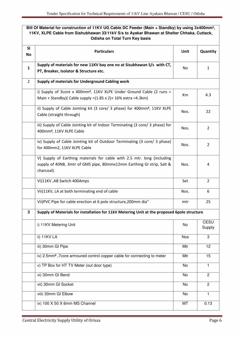
TECHNICAL SPECIFICATION OF 11KV CLASS PORCELAIN CLAD SWITCHGEAR
1.0 SCOPE:
The scope of this specification is for design, manufacture, testing, and supply of outdoor 11 KV
class porcelain clad switchgear suitable for installation for use in a 3-phase 50Hz, 11KV solidly
earthed system. The switchgear assembly shall consist of complete with all components such as
circuit breakers, control gear, instrument transformers, meters, relays, switches, indicating lamps,
test blocks, current transformers, voltage transformers etc. which are required in each panel for
satisfactory and efficient performance of the switchgear. The switchgear shall suit outdoor
installation.
2.0 APPLICABLE STANDARDS :
The switchgear shall confirm to the following standards namely BIS – Bureau of Indian
Standards and IEC – International Electro Technical Commission.
Sl No IS / IEC Nos Equipments & components.
1 IS 5 Paints, Finishing Exterior
2 IS 513 Cold rolled low carbon steel sheets and strips.
3 IS 641 Paints, Finishing interior White
4 IS 722 A.C. Electricity meters
5 IS 722 Parts(1)to(5) (7)to(9)
Direct acting indicating analogue electrical measuring Instruments
and their accessories.
6 IS 1730 Steel sheet and strip dimensions
7 IS 1951 PVC sleeving for electrical purpose.
8 IS 2419 Dimensions for panel mounted indicating instruments.
and electrical recording
9 IS 2516
/13118 Specification for alternating current Breakers
10 IS 2750
Parts I to IV Current Transformers
11 IS 2959 AC & DC Contractors
12 IS 3156
parts I to III Voltage Transformers
13 IS 3231 Electrical relays for power system protection
14 IS 3427 Metal enclosed switchgear and control gear
for voltages above 1000 V but not exceeding 11000 V

Tender Specification for Technical Requirements of 11kV Line Ayakara Bhawan / CESU / Odisha
Central Electricity Supply Utility of Orissa Page 11
3.0 NORMAL SERVICE CONDITIONS :
Generally as per (1) clause 2.1(a) to 9(e) of Is 13118 Clause – 2.
DEFINITIONS AND TERMINOLOGY :
As per
15 IS 3842
Parts I to XII
Application guide for Electrical relays for
protection and other relays.
16 IS 4146 Application guide for voltage Transformers
17 IS 4201 Application guide for current transformers
18 IS 477 Performance tests for protective schemes used in
protective of light gauge steel against corrosion
19 IS 4794
parts I to II Push button switches
20 IS 5608
Parts I to IV PVC wires and sheaths
21 IS 6236 Direct recording electrical measuring instruments
22 IS 6875 Control Switches
23 IS 7118 Recommendation for direction movement for
control device, operating electrical devices.
24 IS 8130 Conductors for insulated Electric cables.
25 IS 8197 Terminal markings of electrical measuring
instruments and accessories.
26 IS 8686 Static protective relays.
27 IS 9224
Parts I to II
Pictorial surface preparation standards for
painting of steel surfaces.
28 IS 9954 Code of practice for installation of switchgear
29 IS 10118 Code of practice for installation of switchgear
30 IS 10276 Edison screw lamp holders
31 IS 11431 Code of practice for packaging of electrical
I Indicating and recording instruments
32 IEC 56 High voltage alternating current circuit breakers1987
33 IEC 694 Common clauses for high voltage switchgear and
control gear standards.
34 IEC 687 Static watt-hour meters for class 0.25 and 0.5
35 IS 14697 Static transformer operated watt-hour and
VAR hour meters class 0.25 and 0.5

Tender Specification for Technical Requirements of 11kV Line Ayakara Bhawan / CESU / Odisha
Central Electricity Supply Utility of Orissa Page 12
Ref Nos Ref Clauses
i IS-3427 Clause- 2 and sub clauses there of for switch gear.
ii IEC-56 Clause - 3 and sub clauses there of for circuit breakers
iii IS-13118 Clause - 3 and sub clauses there of for circuit breakers
iv IS-2705 Part- I to IV clause-2 &sub clauses there of for current transformers.
v IS -3516 Part -I clause-2 &sub clauses there of for voltage transformers
4.0 DESIGN AND CONSTRUCTION:
4.1 GENERAL.
4.1.1 The Circuit breaker shall be provided with vacuum interrupters hermetically Sealed. The
vacuum bottles are to be mounted in side porcelain enclosure and Placed on a sheet metal
enclosure having main operating links. The mechanism is to be placed under this and
connected by a link, which transmits mechanical power to circuit breaker. The entire assembly
shall be mounted on an elevated structure to provide live point clearance as per IS 10118.
4.1.2 Control and relays shall be mounted in out door sheet steel KIOSK. The minimum thickness of
the galvanized steel sheet shall not be less than 3.5 mm for the base and load bearing
members and not less than 3.0 mm for the top cover, side sheets, doors and partitions.
Galvanized Sheet steel shall be cold rolled confirming to IS –513. The panel door shall be
provided with louvers and with translucent plastic covered windows directly opposite to the
close/open indicating lamps and spring status indicator. The panel door shall be hinged, swing
door provided with pad locking facility. Rear door shall also be hinged on one side and bolted
on the other side.
4.1.3 The design and construction shall be with the following features:
a) Compact and robust construction.
b) Dust protected and vermin proof
c) Safe and positive interlocks.
d) Easy interchangeability of identically rated components including breakers.
e) Extremely reliable operation.
f) All relays, instruments, and switches mounted on the instruments panel shall be
accommodated at a height in between 0.5 to 2.0 meters from ground level in the
outdoor control panel.
4.1.4 Auxiliary devices and circuits :
Generally as per clause 3.2.7 of IS 3427.

Tender Specification for Technical Requirements of 11kV Line Ayakara Bhawan / CESU / Odisha
Central Electricity Supply Utility of Orissa Page 13
4.2 INTERLOCKS : Generally as per clause 3.4(e) with mechanical interlocks of IS 3427.
4.3 EARTHING :
Generally as per 3.5 of IS 3427. However the earthing conductor shall be of copper flat shall
not be less than 25 X 6 mm. Earthing shall be suitable to receive 50 X 6 mm GI flat of station
earthing in the 2 bolts of M.12 size.
4.4 SWITCHGEAR COMPONENTS:
The following shall be components in the PC, VCBs.
� Vacuum interrupters mounted in porcelain enclosures
� Current transformer
� Instruments and protective relays selector switches
� Interconnections between breaker and instrument transformers
� Terminal connectors to receive ACSR Lynx conductor
� Control switches, indicating lamps, contactors and test terminal blocks
� Voltage transformer.
� Control cabling from instrument transformers secondary box to control and relay kiosk with
cable glands.
4.5 GENERAL ARRANGEMENT OF COMPONENTS: 4.6 Various switchgear components are to be arranged.
4.7 The interconnections are in scope of supply of the tenderer.
4.8 The following shall be provided in each panel as applicable a) Cubicle space heater with thermostat
b) View glass for breaker position indication
c) Names plates
d) Danger board
e) Operation counter for the breaker
f) Spring charging handle
5.0 GENERAL ARRANGEMENT OF THE SWITCHGEAR PANELS:
4.1 The kiosk where control equipments are housed shall be provided with a lean to drain water to
the rear of the panel. The proof shall be projecting on all sides so that rain water shall not
enter into the body of the panels.
4.2 The central annunciator panel shall be suitable for mounting indoor. Remote close / Trip
facility shall be provided on this panel itself for remote closing /opening of individual breakers.
6.0 SWITCHGEAR RATINGS:
6.1 CHARACTERISTICS :

Tender Specification for Technical Requirements of 11kV Line Ayakara Bhawan / CESU / Odisha
Central Electricity Supply Utility of Orissa Page 14
� Rated voltage as per clauses 4.2 if IS 3427 for nominal system voltage of 11 KV
� Rated insulation level 28KV / 75KV peak – for 11KV nominal system voltage.
� Rated frequency – 50Hz
� Rated normal current – 1250A for incomer /800A for feeder.
� Rated short – time current – 20 KA
� Rated Peak short – time current,. As per clause 4.7 of IS – 3427 and in conjunction
with sub-clauses (e) supra.
� Degrees of protection. Corresponding to IP 55 of Is-12063.
� The temperature rise limits for the various materials shall be as per table – V of IEC
694.
7.0 SWITCHGEAR COMPONENTS:
Rated values of the components forming part of the meal enclosed switchgear and control
gears are detailed here below individually against each component.
7.1 Circuit breakers :
a) Type : vacuum
b) Rated voltage 11KV rms.
c) Highest system voltage 12KV rms.
d) Frequency 50Hz
e) Number of poles – three
f) Class outdoor.
g) Power frequency withstand voltage: 258KV rms.
h) Impulse with stand voltage- 75KVP
i) Rated normal current –630 A.
j) Rated symmetrical breaking current- 25KA
k) Rated transient recovery voltage: as per clauses 4.102.2,4.102.3 of
IEC 56, table – II A for 12KV rated voltage.
l) Rated making current peak : 50 KVA
m) Short time withstand current – 25KA for 3 seconds.
n) Operating sequence : As per clause 4.104 (a) of IEC – 56 0-3min-co
o) Rated supply voltage of opening /closing devices with operating
limits.
6.1.1 Closing coil- 110V.DC – to operate satisfactorily between 85 to 110 % of rated voltage.
ii) Opening coil (shunt trip coil) – 110V DC to operate satisfactorily between 70 to 100% of rated Voltage
p) Rated voltage of auxiliary supplies.

Tender Specification for Technical Requirements of 11kV Line Ayakara Bhawan / CESU / Odisha
Central Electricity Supply Utility of Orissa Page 15
i) Space heater -AC 230V, S.Ph 50 Hz.
ii) Spring charging motor – AC 230V, S.Ph 50 Hz.
iii) Cubical illumination – AC 230V, S.Ph. 50 Hz.
q) Method of closing and opening – The breaker shall be capable of discharging the energy
stored in spring. These springs should be capable of being compressed or charged by an
AC motor. It should be possible to charge the springs manually by means of a spring
charging handle or lever. During manual charging of the springs an electromechanical
device shall be provided to prevent charging of the same by the motor. The springs should
also be capable of being charged even with the breaker in the closed position so as to
restore tension in the springs. Besides, there should be provision to automatically cut – off
power supply to the motor when the springs are fully charged and also to automatically
switch – on the power supply to the motor when the springs are fully discharged. There
shall also be provision to indicate springs status namely “FREE” / “Charged “ by means of
a mechanical lever at the panel. This shall be arranged through potential free auxiliary
contacts or limit switches. The mechanism shall be provided with an anti pumping device
to prevent closing impulses from being transmitted, to the closing coil when the breaker is
in the closed position.
r) Auxiliary Contacts : 8 No+8NC conforming to clause 5.4 of IEC 694.
s) Name Plates …. As per clause 5.9 of IEC 56. t) Requirements for simultaneity of poles – As per Clause 5.101 of IEC 56.
7.2 CURRENT TRANSFORMERS
7.2.1 The current transformers shall conform in all respects to IS – 2705 parts I to IV.The
arrangement of current transformers in porcelain clad switch gear is shown in sketch 1&2.
7.2.2 CTs shall be encapsulated resin cast or poly crate to suit outdoor instalation.
7.2.3 CT ratio changing is preferred on Secondary side.
7.2.4 Rating characteristics:
a. Nominal voltage : 11kV rms.
b. Highest system voltage : 12kV rms
c. Frequency : 50 Hz.
d. Power frequency withstand Voltage : 28kV rms
e. Impulse with stand voltage : 75kVp
f. Ratio and Cores : 3 cores 20-10/1-1-1A

Tender Specification for Technical Requirements of 11kV Line Ayakara Bhawan / CESU / Odisha
Central Electricity Supply Utility of Orissa Page 16
g. Accuracy class- burden
Core 1 (metering ) : 0.5/15VA
Core 2 (OCR,EFR &
REFR Protection) : 5 P20/15VA
Core 3 (differential
Protection) : PS/VK Min 300V
h. Instrument security factor : 5 at all ratios
i. Earthing : As per clause 4.3
of IS 2705 (part-1)
j. Short time current Rating
i. Thermal rating : 25 KA for 1 second
ii. Dynamic rating : As per clause 562 of IS2705 part-I
k. Terminal Marking : As per Clause 6.2 of IS 2705 part-I
l. Rating Plate : As per Clause 6.1 & 7.1 of 2705
7.3 METERING INSTRUMENTS:
7.3.1 Meters to be mounted shall conform with IS 1248 Parts (I to IX) and dimension shall conform
to IS-2419.
7.3.2 All meters shall be CT/VT Secondary operated instruments and shall be flush mounted with only the bezels projection.
7.3.3 All meters shall be wired at the back and shall be provided with tropicalised dials, to ensure freedom from warping, iscoloration or fading.
7.3.4 The lettering/Numbering on dials shall be in bold black on white dial background.
7.3.5 All meters shall be magnetically shielded.
7.3.6 All indicating analog meters shall be provided with a screw type zero adjuster for the needle with facility to operate from the front of the panel without having to remove the cover of the meter.
7.3.7 All meters shall be wired through test terminal blocks to facilitate independent calibration of meters.
7.3.8 TYPE RATING AND CHARACTERISTICS: A) AMMETER:
i) One No. to be provided. The ammeter shall be provided with a selector switch to read the current in each of the phases.
ii ) Moving Iron. iii) Size – 96*96 mm
Iv) Accuracy…….1.0
V) Scale 0 – 5 – 10 - 20

Tender Specification for Technical Requirements of 11kV Line Ayakara Bhawan / CESU / Odisha
Central Electricity Supply Utility of Orissa Page 17
B) Watt meter:
I. One number to be provided in each panel. II. Type: 3 phase3 wire two element dynamometer. III. Size 96 X 96 mm. IV. Accuracy class: 1.5. V. Range: 0-200 KWS
VI. Scale : 90 degrees and end suppressed
C) VAR Meter:
I. One number to be provided in each panel.
II. Type: 3 phase 3 wire two element dynamometer.
III. Size 96 X 96 mm.
IV. Accuracy class: 1.5.
V. Range: 0-200 KVAR
VI. Scale: 90 degrees and end suppressed
D) Electronic Tri vector Meter:
I. One number to be provided
II. It shall be static type 3 phase, 3 wire, 2 element, suitable for 1
amp CT & 110 volts phase to phase V.T secondaries. It must be
flush mounted type & tropicalised. It shall have separate registers
for recording kWHr & kVAHr consumption seperately, maximum
demand (with resetting facility), both for import and export modes.
III. The accuracy class shall be 0.5.
IV.The meter shall have legible LED/ LCD minimum 6 digit auto
cycle display and non volatile memory with out battery back up.
V.The meter shall have galvanically isolated optical.
VI.The meter shall be capable of storing the complete half hourly
data required for load analysis & energy audit for a period of 35
days
VII.communication port for down loading the data to an MRI or to
DCD or to a modem.
VIII.The meter shall have self diagnostic feature to check its circuits
for any malfunctioning.
7.4 Protective Relays:
The relays to be mounted in front of the panel Electornic draw out type, suitable for 3ph,
one amp CT secondary current , 110 volts ph to ph VT secondary, and 110 volts D.C.
auxiliary.

Tender Specification for Technical Requirements of 11kV Line Ayakara Bhawan / CESU / Odisha
Central Electricity Supply Utility of Orissa Page 18
The following relays are to be provided.
a) Electronic Relay: Combined unit for OCR & EFR for line side.
7.5 Control switches: 7.5.1 General :
The control switch shall contain two electrically independent double break contacts and shall
be moulded in a self – extinguishing plastic compound with inherent arc – quenching and high
insulating property enclosed moulding giving a high degree of dust protection. The back of
control switch is to be shrouded in transparent cover, automatic spring return to neutral switch
type to be provided. The switches shall be suitable for 20 Amps continuous rating and 110V
DC.
7.5.2 Requirement : a. One No. in each outgoing panel.
b. One No. for each outgoing breaker in the annunciator panel for remote operation.
7.6 SELECTOR SWITCHES (FOR AMMETER AND VOLTMETERS)
7.6.1 General : These shall be slow – break, quick-make, rotary type, stay put switches, and shall be suitable
for flush mounting. These switches shall be suitable for being operated by flush mounting.
These switches shall be suitable for being operated by a knob from the front face of the panel.
They shall be suitable for 10 Amps continuous rating and 415V AC. The ammeter selector
switches shall short – circuit the CT secondary before it is broken and remove the short circuit
after the ammeter is inserted in the circuit. All the switches shall have position indication plates
4 ways i.e., R, Y, B and OFF.
7.7 Indication lamps:
7.7.1 Indication lamps shall be integral LED module type 0.5 watts, suitable for 110 volts D.C.and
these shall be integral self contained LED indicator units which can be directly mounted in the
panel. The rated input voltage can be directly applied to the module input as all the controlling
circuitary is built is built in to the module body it self. These modules shallbe suitable for panel
cut outs of size 22.5mm dia with the use of crome plated standard mounting adopter / bezel
sets and colours RED, GREEN,ABMER/YELLOW, WHITE, & BLUE. The axial light intensity
should be min 40 milli candella.
7.7.2 COLOUR CODE FOR LAMPS:
� Breaker open : Green
� Breaker Closed : Red
� Auto trip : Amber
� Spring charged : Violet / Blue
� Trip Circuit Healthy : White
Tender Specification for Technical Requirements of 11kV Line Ayakara Bhawan / CESU / Odisha
Central Electricity Supply Utility of Orissa Page 19
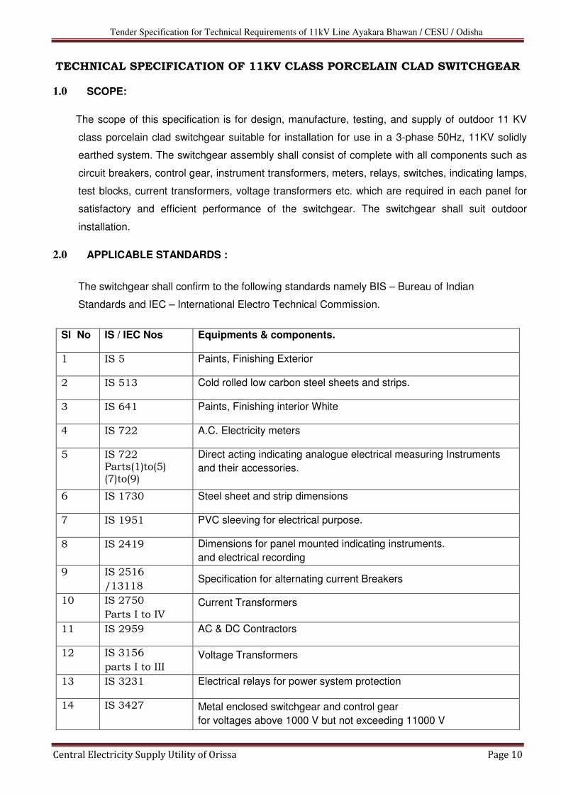
7.7.3 REQUIREMENT OF LAMPS
a) One set of green, amber and red lamps in each incomer and outgoing panels along with
spring status violet / Blue and trip circuit healthy white on command.
b) One set of green, red, amber, violet / blue and white lamps for indicating the status of each
incomer and outgoing breakers in the remote indoor annunciation panel
7.7.4 10% of the total of integral LED module type lamps for each panel shall be supplied as spare
without extra cost.
7.8 FUSES:
6.8.1 GENERAL:
All fuses shall be moulded bakelite complete with fuse bases, fuse carriage and HRC cartridge
fuses. All fuse fittings should be labeled by etching on an anodized plate with details of the
fuse rating and the circuit for which the fuse is provided.
6.8.2 RATING:
i. AC 115V for all supply fuses. ii. DC 110V for DC circuits
1.8.3 Rated Current : AS per clause 5.3 of IS 9224 (Part-I) 1979 (Preferred value of rated current 32
Amps)
6.8.4 REQUIREMENTS:
All AC and DC circuits shall be provided with suitable fuses and fuse links for each phase /
pole.
6.8.5 10% of the H.R.C fuse cartridge shall be supplied as spares without Extra cost.
7.9 WIRING:
7.9.1 GENERAL:
The wiring shall be done by using PVC-insulated 660 V annealed, stranded Copper
wire. The wires shall run straight and shall be given right angle bends wherever necessary so
as to give a pleasing appearance. The size of wiring in difference circuits shall not be less
than the sizes specified below:
a) Metering and Relay circuits : 2.5 Sq.mm connection from CT’s and VT’s
b) All terminal connections to the equipments and terminal blocks shall be
done by using Tin coated Copper lugs. All the outgoing wiring from the
panel shall be terminated on the terminal block mountd in the front of the
panel with suitable provision for connection to the interconnecting control
cable. The wiring shall conform to IS 375 with latest amendments if any.

Tender Specification for Technical Requirements of 11kV Line Ayakara Bhawan / CESU / Odisha
Central Electricity Supply Utility of Orissa Page 20
c) All wiring shall be provided with alphanumeric ferules at either ends as
per the wiring schedule.
d) All terminals shall be nut & stub type of brass coated with Nickle of size
M6.
7.10 TEST TERMINAL BLOCKS:
The Test terminal blocks required are for testing while in service and shall be of the 3 phase 4
wire, front adjustable, link type, projected, mounted with screwed cover and wired at the rear,
rated for 10 Amps, The wiring shall be so as to short circuit the CT phase to the star point and
it shall be possible to calibrate through external injection.
7.11 Galvanising
7.11.1 All the steel frame work and surface of the steel panels shall be fully galvanized to with stand
saline weather in the coastal areas.
7.11.2 Block No. shall be assigned for each compartment and the same shall be stencilized in white
paint on the inside of panel.
7.12 TERMINAL PAD / CONNECTORS: The Terminal Connectors for CTs and porcelain clad breakers shall suit to receive ACSR Lynx
of 10 mm dia minimum 4 bolt connection.
7.13 FOUNDATION BOLTS: Foundation bolts with 10% spares are in the scope of supply of the supplier.
7.14 AUXILARY DC SUPPLY : The auxiliary 110 V D.C. supply will be arranged from station battery panel.
7.15 AUXILIARY AC SUPPLY: The auxiliary A.C. supply at 3phase 415 volts will be arranged from the Biomass generating
unit 1 & 2
7.16 INDOOR TYPE COMBINED REMOTE CONTROL & ANNUNCIATOR PANEL.
7.16.1 General: Sloping desk type / free standing panel, with audio visual annunciator facia windows on the
inclined slope along with annunciator lamp test, accept and reset push buttons. All control
switches in the run of the mimic bus with indicating lamps mounted on the horizontal desk.
The base of the desk shall be provided with vermin – proof sheet metal cover and cable
gland, to receive the control cables from the outdoor panels. The annunciator shall be
electromechanical.

Tender Specification for Technical Requirements of 11kV Line Ayakara Bhawan / CESU / Odisha
Central Electricity Supply Utility of Orissa Page 21
7.16.2 Wiring: All wiring from the outdoor panel shall be terminated on the terminal blocks inside the
cubicle. The terminal block shall be Brass stud and nut type of size M6. The terminal blocks
shall be of moulded resin type provided with plastic shrouds. Sufficient spare terminals shall
be provided on the terminal blocks. Paint shade of annunciator panel shall be opaline green
of shade No. 275 of IS – 5
7.16.3 Annunication facia windows shall be with plastic facia sheet engraved with letters of 5 mm
size. The inscriptions shall be visible only when the facia is lighted. The lamps shall be
suitable for 110 V DC with an in – built resistor. The initiation of annunciation shall be
through NO-NC contracts of the relay.
A hooter suitable for 110V DC shall be installed in the annunciator panel for alarms
7.16.4 REQUIREMENT OF ENGRAVING IN THE ANNUNICIATOR DESK:
i. No. of Windows 5
OCR R Phase operated 1 >
OCR B phase operated 1 > Trip alarm
EFR operated 1 >
Deferential relay operated 1
DC fuse failure 1 > Non Trip
No. of windows spare 1
Master trip relays 1
ii. Breaker open indication lamp 1
iii. Breaker close indication lamp 1
iv. Spring free/charged indication lamp 2
v. Breaker auto trip 1
vi. Trip/Neutral/Close switch 1
8.0 TESTS:
8.1 TESTS ON SWITCH GEAR:
8.1.1 Type tests:
As per clause 8.1.1 – (a) to (e) and (h) and (j) of IS 3427 – 1969.

Tender Specification for Technical Requirements of 11kV Line Ayakara Bhawan / CESU / Odisha
Central Electricity Supply Utility of Orissa Page 22
8.1.2 Routine Tests:
As per clause 8.12 – (1), (b) & (e) of IS – 3427 – 1969.
9.1 TESTS ON CIRCUIT BREAKERS:
9.1.1 TYPE TESTS:
As per clause 6.0 of IS 13118.
9.1.2 ROUTINE TEST:
As per clause 7.0 of IS 13118.
9.2 TEST ON CURRENT TRANSFORMERS :
9.2.1 TYPE TEST :
a) As per clause 7.1.1(a) to (h) of IS 2705 (Part-I)-1981.
e) As per clause 8.1 of IS 2705 (Part-II)- 1981.
f) As per clause 8.2 of IS 2705(Part-III)-1981.
g) As per clause 8.3 of IS 2705(Part-III)-1981.
h) As per clause 6 of IS 2705(Part-iv).
9.3 TEST ON VOLTAGE TRANSFORMERS :
9.3.1 TYPE TESTS:
i) As per clause 6.1.1 of IS 3156(part-1)-1978.
a. As per clause 8.1 of IS 3156(part-II), 1978.
b. As per clause 9.1 of IS 3156(part-III)-1978.
9.3.2 ROUTINE TESTS:
i) As per clause 8.1.2 of IS 3156(part-I)-1978.
ii) As per clause 8.2 of IS 3156(part-II- 1978. As perclause 9.2 of IS 3156(part-III)-1978.
9.4 TESTS ON RELAYS:
9.4.1 Type tests and routine tests as per IS 3231 and IEC 255 shall be conducted.
9.4.2 TYPE TESTS:
Type test reports not older than 5 years on the date of bid opening, pertaining to all type tests
stipulated in IS 3231 and other tests conducted shall be furnished along with the bid
document.
9.4.3 All routine tests shall be carried out in the presence of the owner’s representative for which
sufficient advance intimation shall be given.
9.5 All instruments, relay, and other components shall be provided with name plates at their rear
and shall be supplied separately as dissembled components.
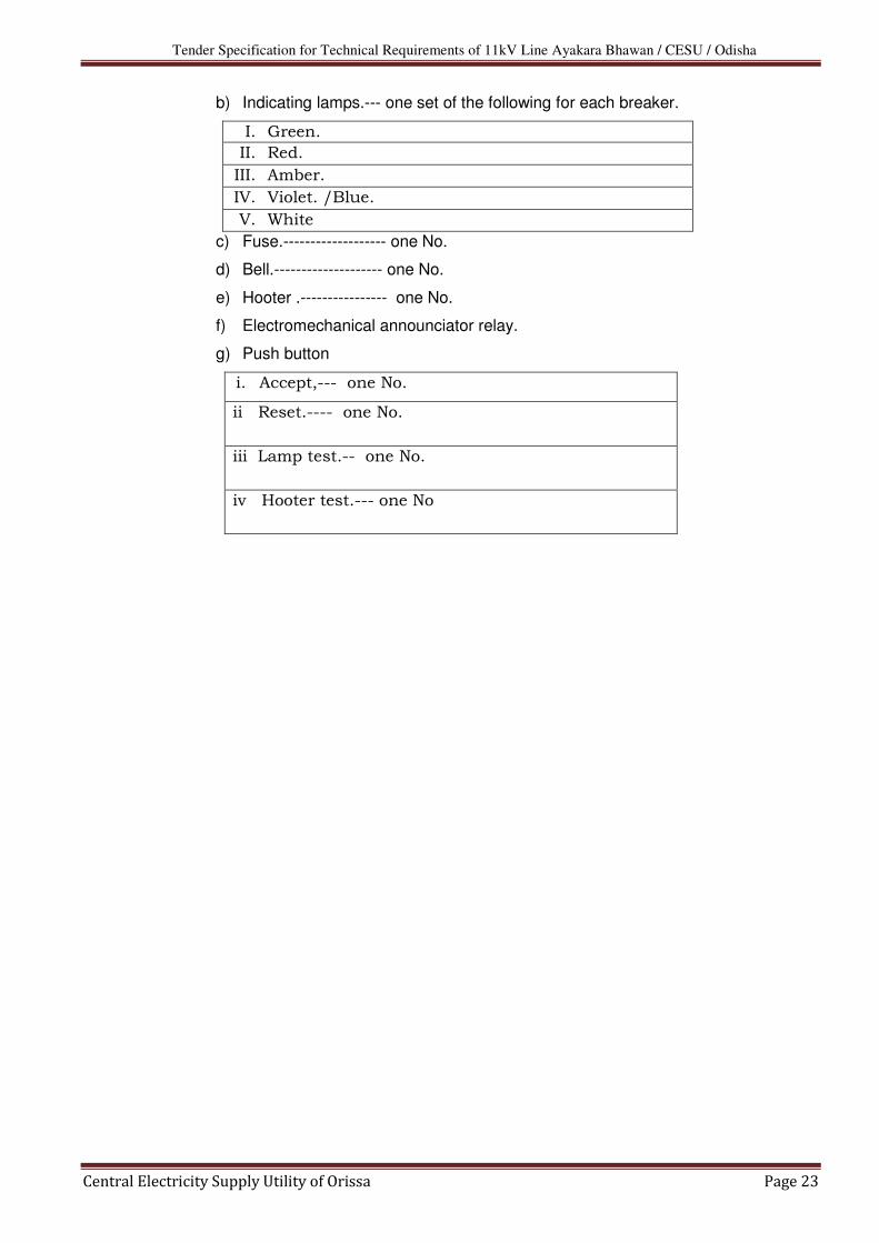
10.0 INDOOR COMBINED ANNOUNCIATOR AND REMOTE CONTROL PANEL:
a) Control Switch.---- one number for each breaker.
Tender Specification for Technical Requirements of 11kV Line Ayakara Bhawan / CESU / Odisha
Central Electricity Supply Utility of Orissa Page 23
b) Indicating lamps.--- one set of the following for each breaker.
I. Green.
II. Red.
III. Amber.
IV. Violet. /Blue.
V. White
c) Fuse.------------------- one No.
d) Bell.-------------------- one No.
e) Hooter .---------------- one No.
f) Electromechanical announciator relay.
g) Push button
i. Accept,--- one No.
ii Reset.---- one No.
iii Lamp test.-- one No.
iv Hooter test.--- one No

Tender Specification for Technical Requirements of 11kV Line Ayakara Bhawan / CESU / Odisha
Central Electricity Supply Utility of Orissa Page 24
Section-III
11kV UG Cable

Tender Specification for Technical Requirements of 11kV Line Ayakara Bhawan / CESU / Odisha
Central Electricity Supply Utility of Orissa Page 25
TECHNICAL SPECIFICATIONS FOR 11KV, XLPE INSULATED UG CABLE
1.0 SCOPE :
1.1 The scope of this specification covers the design, manufacture, stage inspection at works,
inspection and testing the finished cables 6.35 /11KV aluminum conductor. Three Core,
400 mm², XLPE insulated screened, underground cables at manufacturer’s works.
2.0 RATED VOLTAGE
2.1 The rated voltage of the cable shall be 11000 Volts AC with the highest system voltage of
12000 Volts between phases of the effectively earthed three phase-distribution system.
3.0 APPLICABLE STANDARDS:
3.1 Unless otherwise stipulated in the specifications, the latest version of the following
Standards shall be applicable.
a. IS 8130 – Conductors for Insulated electrical cables and flexible cords
b. IS 10810 (series) – Methods of tests for cables
c. IS 10418 – Drums for electrical cables.
d. IS 7098 (Part 2) – Cross – linked Polyethylene Insulation for Cables.
e. IS 3975 – Specification for mild steel wires, strips and tapes for armoring of
cables.
f. IS 5831 – Specification for PVC insulation sheath for electric cables.
Dimensions of protective coverings of cables
Part 1 – Elastomeric and thermoplastic insulated cables.
3.2 The Cables manufactured to any other Internal Standards like BSS, IEC or equivalent
standards not less stringent than Indian Standards are also acceptable. In such cases, the
Bidders shall enclose a copy of the equivalent international standard, in English language,
along with the bid.
4.0 CONSTRUCTION:
4.1 Conductor :- The conductor shall be composed of compacted circular aluminum
wires complying with IS 8130.
4.2 Insulation : - The insulation shall be cross linked polyethylene conforming to the following
requirements.
Sl.NO. Properties Requirements
1. Tensile Strength 12.5N/mm2, Min.
2. Elongation to break 200 percent, Min
3. Aging in air oven :
Treatment : Temperature
Duration
135+_3
0 C
7 Days
Tensile Strength variation : + 25 percent, Max
Elongation variation: + 25 percent, Max
4. Hot set :
a) Treatment : Temperature:
Time under load
Mechanical stress
200 + 30 C
15 min
20N/cm2

Tender Specification for Technical Requirements of 11kV Line Ayakara Bhawan / CESU / Odisha
Central Electricity Supply Utility of Orissa Page 26
b) Elongation under load 175 percent, Max
c) Permanent elongation (set) after cooling 15 percent, Max
5. Shrinkage:
a) Treatment : Temperature
Duration
130+ 30 C
1 hour
b) Shrinkage 4 percent, Max
6. Water absorption (Gavin metric) :
a) Treatment : Temperature
Duration
85+ 20 C
14 days
b) Water absorbed 1 mg / cm2, Max
7. Volume Resistivity
a) at 270 C
b) at 700 C
1 x 10¹⁴ ohm-cm, Min
1 x 10¹³ ohm-cm, Min
4.3 The screening shall consist of non-metallic semi conducting compound and copper tape,
shielded cores laid up with fillers, inner sheath of extruded PVC, Galvanized steel strip
Amour and PVC ST-2 overall sheath.
4.4 The cables should be suitable for use in solidly earthed system.
4.5 The 6.35/11KV underground cables shall be manufactured to the highest quality, best
workmanship with scientific material management and quality control. The bidder shall
furnish the quality plan, giving in detail the quality control procedure / management system.
4.6 The successful Bidder shall give sufficient advance notice to the purchaser of not less
than fifteen days to arrange for stage inspection and inspection of quality assurance
program during manufacture, at the works.
5.0 SYSTEM DETAILS
General Technical particulars
General Technical particulars
Sl No Particulars Values
1 Nominal system voltage (rms) (U) 11KV
2 Highest system voltage (rms) (Um) 12KV
3 Phase to Earth voltage (rms) (U0) 6.35 KV
4 Number of Phase 3
5 Frequency 50Hz
6 Variation in Frequency + / - 3%
7 Type of Earthing Solidly Earthed
8 Basic impulse insulation level (1.2/50 µS wave) 75 KV
9 Total relay & circuit breaker Operating time 15-20 cycles
10 One Minutes power frequency withstand voltage 28 KV rms

Tender Specification for Technical Requirements of 11kV Line Ayakara Bhawan / CESU / Odisha
Central Electricity Supply Utility of Orissa Page 27
6.0 INSTALLATION CONDITIONS :
6.1 The cables are laid directly buried in ground, in the bores formed by horizontal boring
method. The Nominal depth of laying is up to 2000 mm (from top, of ground to centre of
cable).However, in trenchless horizontal bore method, the bore can go upto a depth of a
maximum of 2 meter. Nature of soil is heterogeneous, sandy, Soil resistivity varies between
18 to 100 ohmmeter and the Thermal resistivity is around 1200 to 1500 C/ Cm/w.
7.0 CLIMATIC CONDITIONS :
7.1 The climatic conditions where these 11KV cables will be installed are as under :
Climatic conditions
Sl No Particulars Details
1 Location: Cuttack, Orissa
2 Altitude As is coastal area, altitude will Not exceed
100 M above MSL.
3 Max Daily average air temp : 45 0 C
4 Minimum ambient air temp : 10 0 C
5 Ground temperature at
depth of laying assumed :
350 (Max) 50 C (Min)
6 Isoceraunic level 45
7 Avg. annual rainfall : 2500 mm
8 Avg. number of rainy days
per annum:
90
9 Climate: Tropical moderately hot and humid.
likelihood of subsoil water at certain location
at the depth of burial of cables..
10 Soil : Normally wet
8.0 DESIGN CRITERIA :
8.1 The cables that are covered in these specifications are intended for use in the Coastal belt
of state of Orissa for Power distribution purposes, under the climatic conditions and
installation conditions described in the technical specification.
8.2 Any technical features, not specifically mentioned here, but is necessary, for the good
performance of the product, shall be incorporated in the design. Such features shall be
clearly brought out under Technical deviations schedules only, in the offer made by the
bidder, giving technical reasons, and justifying the need to incorporate these features.’
8.3 For continuous operation of the cables, at specified rating, the maximum conductor temperature shall be limited to the permissible value as per the relevant standard, generally not exceeding 90°C under normal operation and 250°C under short-circuit conditions.
8.4 The cables in service will be subject to daily load cycles, of two peaks during a day; morning peak and evening peak, with around 50% loading during the nights.
8.5 The materials used for outer sheaths shall be resistant to oils, acids and alkalis. 8.6 The cables shall have the mechanical strength required, during handling and laying. 8.7 The cables shall be designed to withstand the thermo-mechanical forces and electrical
stresses during normal operation and transient conditions. 8.8 The cables shall be designed to have a minimum useful life span of Thirty years.
Tender Specification for Technical Requirements of 11kV Line Ayakara Bhawan / CESU / Odisha
Central Electricity Supply Utility of Orissa Page 28
9.0 MANUFACTURE PROCESS:
9.1 Cross-linking of the insulation materials (pre compounded polyethylene) shall be conforming to IS :7098 (Part-II)
9.2 The conductor screen shall be extruded semi conducting compound. The insulation screen shall consist of the nonmetallic part, extrude semi conducting compound with non-magnetic metallic part. The XLPE insulation and the shield for conductor and insulation shall be extruded in one operation.
10.0 MATERIALS
10.1 Conductor: - The conductor shall be of standard construction. The material for
conductor shall consist of the plain aluminum of H2 or H4 grade as per clause – 3 of IS
8130 / 1984.
10.2 The Number of wires in the conductor, shall be not less than the appropriate minimum
number given in table – 2 of IS 8130 / 1984.
11.0 SCREENING :
11.1 The conductor screening shall be provided over the conductor by applying non-metallic
semi-conducting compound. The metallic screen shall withstand the operating temperature
of the cable and shall be compatible with the insulating material.
11.2 The insulation screen shall be applied over the insulation. The insulation screening
shall consist of two parts; namely metallic and non-metallic. The non-metallic part shall be
applied directly over the insulation of each core and shall consist of a semi conducting tape
and extruded semi conducting compound with a semi conducting coating. The metallic
part of the insulation screen shall consist of either tape, or braid, or concentric serving of
wires or a sheath; shall be non-magnetic and shall be applied over the non-metallic part.
12.0 CORE IDENTIFICATION:
12.1 The core identification for 3 core cables shall be provided, by suitable means, like, by application of colored stripes, or by numerals or by printing on the cores as per clause 13 of IS : 7098 – Part 2.
12.2 For identification of different coloring of XLPE insulation, or by using colored strips, red, yellow and blue colors respectively shall be used to identify the phase conductors.
13.0 LAYING UP OF CORES:
13.1 For multicore cables, the cores shall be laid together with a suitable right hand lay. The interstices at the center shall be filled with a non-hygroscopic material.
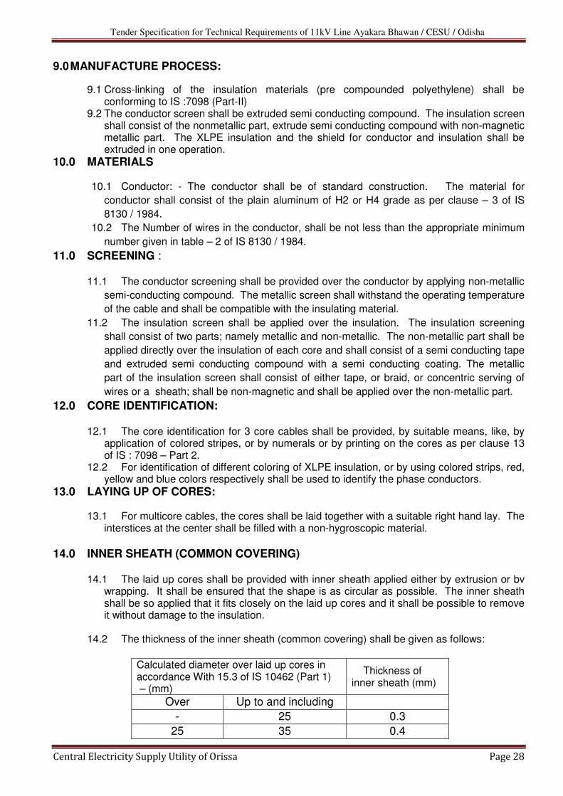
14.0 INNER SHEATH (COMMON COVERING)
14.1 The laid up cores shall be provided with inner sheath applied either by extrusion or bv
wrapping. It shall be ensured that the shape is as circular as possible. The inner sheath shall be so applied that it fits closely on the laid up cores and it shall be possible to remove it without damage to the insulation.
14.2 The thickness of the inner sheath (common covering) shall be given as follows:
Calculated diameter over laid up cores in accordance With 15.3 of IS 10462 (Part 1) – (mm)
Thickness of inner sheath (mm)
Over Up to and including - 25 0.3
25 35 0.4

Tender Specification for Technical Requirements of 11kV Line Ayakara Bhawan / CESU / Odisha
Central Electricity Supply Utility of Orissa Page 29
35 45 0.5
45 55 0.6
55 - 0.7
When one or more layers of binder tapes are applied over the laid up cores, the thickness
of such tapes shall not be construed as a part of inner sheath.
14.3 For multi core cables, the interstices at the center shall be filled with a non-hygroscopic
material. The interstices around the laid up cores shall be covered with PVC compound
type ST-2. This will form the Inner sheath for multi core-single core cables.
15.0 ARMOURING:
15.1 Armoring shall be applied over the inner sheath as closely as practicable. The Amour
shall be galvanized steel strip complying with the requirements of IS 3975. A binder tape
may be applied on the Amour. The direction of the lay of the amour shall be left hand. For
double armored cables, this requirement applies to the inner layer. The outer layer shall be
applied in the reverse direction to the inner layer, and there should be a separator of the
non hygroscopic material; such as plastic tape, bituminized cotton tape, rubber tape,
proofed tape between inner and outer layers of Amour.
15.2 The dimensions of galvanized steel strips shall be as below:
Calculated diameter over Amour [IS 10462 Part 1] (mm)
Nominal thickness of Steel Strip(mm)
Over Upto and including - 13 -
13 25 0.8
25 40 0.8
40 55 1.4
55 70 1.4
70 - 1.4
15.3 The joints in the strips shall be made by brazing or welding and the surface
irregularities removed. A joint in the strips shall not be less than 300 mm away from the
nearest joint in any other strip in the completed cable.
15.4 Bidders shall furnish the calculation / data sheet for the short circuit carrying capability
of the Armour.
16.0 OUTER SHEATH : 16.1 The outer sheath over the Armoring shall consist of poly vinyl chloride (PVC)
compound, conforming to the requirements of type ST-2 of IS 5831. Suitable additives
shall be added to give anti termite protection.
16.2 The minimum thickness of the PVC outer sheath shall not fall below the following value
by more than 0.2 mm + 0.2 ts
Calculated diameter under the outer sheath [IS 10462 Part 1] - mm
Nominal thickness of the Outer
sheath (ts) - mm
Over Upto and including - 15 1.8
15 25 2

Tender Specification for Technical Requirements of 11kV Line Ayakara Bhawan / CESU / Odisha
Central Electricity Supply Utility of Orissa Page 30
25 35 2.2
35 40 2,4
40 45 2.6
45 50 2.8
50 55 3
55 60 3.2
60 65 3.4
65 70 3.6
70 75 3.8
75 - 4
17.0 IDENTIFICATION :
17.1 The outer sheath shall have the following information embossed or indented on it; the
manufacturer’s name or trade mark, the voltage grade, the year of manufacture and the
letters “CESU”. The identification shall repeat every 300/350-mm along the length of the
cable.
17.2 Note: The outer sheath of the cable should be embossed with“CESU”.
18.0 INSPECTION AND QUALITY CONTROL :
18.1 The Bidder shall furnish a complete and detailed quality plan for the manufacturing
process of the cable. All raw materials shall conform to relevant applicable standards and
tested for compliance to quality and requirement. During the manufacturing process, at all
stages, inspections shall be made to check the physical and dimensional parameters, for
verification to compliance to the standards. The bidder shall arrange, for inspection by the
purchaser, during manufacture, if so desired by the purchaser, to verify the quality control
process of the Bidder.
19.0 TYPE TESTS :
19.1 The offered cables with same designs shall have been type tested and Test
certificates shall not be later than 5 years on the date of bid opening. Otherwise the
supplier / Turnkey contractor shall arrange for type testing at his own cost.. The
supplier /Turn Key contractor shall conduct all type tests as per IS : 7098 part-II
1985, with up to date amendments or equivalent International standard, and supplies
made only after approval of test reports from the purchaser.
19.2 All type tests if required, routine; acceptance test shall be conducted in the presence of
the purchaser / representative.
19.3 The supplier shall give 15 days advance notice for inspections, and witnessing of tests
by the purchaser or his representative.
19.4 The following type tests will be conducted on the cable if the type test
certificates are more than 5 years old
(a) Test on conductor.
(b) Test on Amour.
(c) Test for thickness of XLPE insulation and inner and outer sheaths
(d) Physical test on XLPE insulation.

Tender Specification for Technical Requirements of 11kV Line Ayakara Bhawan / CESU / Odisha
Central Electricity Supply Utility of Orissa Page 31
(e) Physical test for outer sheath
(f) Bleeding and blooming test for outer sheath
(g) Partial discharge test.
(h) Bending test
(i) Di-electric power factor test
i. As a function of voltage
As a function of temperature
(j) Insulation resistance (volume resistivity) test
(k) Heating cycle test
(l) Impulse withstand test
(m) High voltage test
(n) Flammability test
19.5 The following test shall be performed successfully on the same test sample of
completed cable, not less than 10 M in length between the test accessories:
I. Partial discharge test
II. Bending test followed by partial discharge test
III. Dielectric power factor as a function of voltage.
IV. Dielectric power factor as a function of temperature
V. Heating cycle test, followed by dielectric power factor as a function of voltage and
partial discharge tests.
VI. Impulse withstand test
VII. High voltage test.
20.0 ACCEPTANCE TEST:
20.1 The sampling plan for acceptance test shall be as per IS 7098 part-II, Appendix ‘A’
20.2 The following shall constitute the acceptance test.
a) Tensile test for aluminum
b) Wrapping test for aluminum
c) Conductor resistance test
d) Test for thickness of insulation
e) Test for thickness of inner and other sheath
f) Hot-set test for insulation
g) Tensile strength and elongation at break test for insulation and outer sheath.
h) Partial discharge test (on full drum length).
i) High voltage test.
j) Insulation resistance (volume resistivity test).
21.0 ROUTINE TEST :
21.1 The following shall constitute routine tests :
a) The following shall constitute routine tests:
b) Conductor resistance test
c) Partial discharge test on full drum length
d) High voltage test.
22.0 PACKING :
22.1 The cables, as per specified delivery lengths, shall be securely wound /packed in non-
returnable, well seasoned sturdy wooden drums, with strong reinforcement so as so to

Tender Specification for Technical Requirements of 11kV Line Ayakara Bhawan / CESU / Odisha
Central Electricity Supply Utility of Orissa Page 32
withstand rough handling during transport by rail, Roads etc., The packing should
withstand storage conditional in open yards. The cable drums shall conform to IS 10418
1982 or equivalent standard.
22.2 The drawings of the cable drums with full detail shall be furnished, and got approved
before dispatch.
23.0 SEALING OF CABLE ENDS ON DRUMS :
23.1 The cable ends shall be sealed properly so that Ingress of moisture is completely
prevented. The individual core endings shall be sealed effectively with water resistant
compound applied over the core ad provided with a heat shrinkable or push-on or Tapex or
cold shrinkable type cap of sufficient length with adequate cushion space so that the
conductor does not puncture the cap in case of movement of the core during unwinding or
laying. Before sealing, the semi conducting layer on the cores may be removed for about 2
mm at each end, to facilitate checking the insulation resistance from one end, without
removing the sealing cap at the other end.
23.2 The three cores should have an overall heat shrinkable or push-on or Tapex or cold
shrinkable type cap with adequate end clearance, and sufficient cushioning to prevent
puncturing of the overall sealing cap due to stretching of the cores. The sealing cap shall
have sufficient mechanical strength and shall prevent ingress of moisture into the cable.
The ends of single core cable shall also be sealed on the same lines to prevent entry of
moisture.
24.0 CABLE LENGTHS :
24.1 The cables shall be supplied in continuous lengths of 250M in case of 3 core cable with
tolerance of + or – 5% of drum length.
It is preferable to manufacture the cable to required lengths as required by the field
conditions to have minimum joints. The turn key contractor will furnish the required drum
lengths in advance
25.0 QUANTITY TOLERANCE
A +3% tolerance shall be allowed on the ordered quantity.
26.0 MARKING:
26.1 The packed cable drum shall carry the following information, clearly painted or stenciled
a) The letters CESU
b) Reference to Standard and ISI mark
c) Manufacturer’s Name or trade mark.
d) Type of cable & voltage grade
e) Number of cores
f) Nominal cross-sectional area of conductor.
g) Cable code
h) Length of cable on the drum
i) Direction of rotation
j) Gross weight
k) Country of Manufacture
l) Year of Manufacture

Tender Specification for Technical Requirements of 11kV Line Ayakara Bhawan / CESU / Odisha
Central Electricity Supply Utility of Orissa Page 33
m) Purchase order and date
n) Address of consignee
27.0 GUARANTEED TECHNICAL PARTICULARS:
Guaranteed technical particulars of the cables to be furnished with the Bid are enclosed.
28.0 DRAWING & LITERATURE
28.1 The following shall be furnished along with the tender a) Cross sectional drawings of the cables, giving dimensional details for each size of
cable.
b) An illustrated literature on the cable, giving technical technical information, on
current ratings, cable constants, short circuit ratings, derating factors, for different
types of installation, packing date, weights and other relevant information.

Tender Specification for Technical Requirements of 11kV Line Ayakara Bhawan / CESU / Odisha
Central Electricity Supply Utility of Orissa Page 34
GURANTEED TECHNICAL PARTICULARS TO BE
FURNISHED BY THE BIDDER
1. CABLES a) Manufacturer
b) Trade Name
2. Type of Cable
3. Applicable specification & Standards
4. Voltage Class
5. Whether suitable for extrusion technique is employed in the manufacture of conductor
screen
6. Whether triple extrusion technique is employed in the manufacture of conductor screen
7. Permissible voltage and frequency variation for satisfactory operation
8. Continuous Current Rating for standard conditions indicated in specifications:
c) Air (450 C Ambient)
d) In Ground (350 C)
e) In Duct
f) In Trench
9. De-rating factors for various laying conditions
10. Conductor
a) Material
b) Shape of conductor
c) Nominal area of cross section
d) Number of strands per core
e) Diameter of Wire (before compacting and stranding)
f) Diameter and size of conductor
11. Conductor Screening
a) Type
b) Material
c) Nominal thickness
d) Continuos working temperature
e) Maximum allowable temperature at the termination of short circuit
12. Insulation
a) Material
b) Thickness of Insulation
c) Thickness of Insulation between cores
d) Thickness of Insulation between cores and inner sheath
e) Tolerance of thickness in insulation
f) Diameter of core over insulation
13. Specific Insulation Resistance at 900C
14. Process of curing
15. Whether XLPE Insulation filled or unfilled
16. Insulation Screening:
a) Material Thickness
b) Thickness of semi conducting part
c) Thickness of metallic part
d) Size of copper tape
e) Whether overlapping provided

Tender Specification for Technical Requirements of 11kV Line Ayakara Bhawan / CESU / Odisha
Central Electricity Supply Utility of Orissa Page 35
f) Current carrying capacity for continuous rating
g) Current carrying capacity for short circuit rating for 1 minutes
h) Diameter of cable over screening
i) Whether insulation screen is removable without the application of heat
17. Inner Sheath
a) Material
b) Extruded
c) Minimum thickness
d) Diameter of cable over inner sheath
18. Armouring:
a) Material
b) Type of Armouring
c) Diameter of wire
d) Whether galvanized
e) Diameter of cable over Armouring
f) Current carrying capacity of Armor
19. Outer Sheath:
a) Material
b) Minimum thickness of sheath
c) Tolerance over thickness of sheath
d) Overall diameter of cable
20. Scheme for identification of cable
21. Allowable/attainable maximum conductor temperature when carrying rated current
continuously
22. Cable constants:
a) DC Resistance per core 200 C
b) AC Resistance per core at operating temperature
c) Reactance
d) Capacitance
e) Insulation Resistance at 270C
f) Loss tangent
g) Dielectric constant – Maximum cable charging current at normal operating voltage
23. Factory Tests (Enumerate in detail for each type of cable)
24. Is the offered cable guaranteed to safely withstand continuous conductor temperature at
900C and also safely withstand temperature upto 1300C for a duration of one hundred
hours per year.
25. Are the offered Three core cable guaranteed to perform satisfactorily under installation
conditions specified? If ‘Yes’ furnish relevant calculations in support including the following
data:
a) Induced voltage in the Amour when a 500 mtr long cable is carrying current
b) Induced voltage and the circulating current in the copper tape

Tender Specification for Technical Requirements of 11kV Line Ayakara Bhawan / CESU / Odisha
Central Electricity Supply Utility of Orissa Page 36
Section-IV
HT cable joints and terminals

Tender Specification for Technical Requirements of 11kV Line Ayakara Bhawan / CESU / Odisha
Central Electricity Supply Utility of Orissa Page 37
TECHNICAL SPECIFICATIONS FOR HEAT SHRINKABLE CABLE JOINT KITS FOR
CABLE TERMINATIONS AND JOINTS
1.0 GENERAL:
1.1.
he term heat shrink refers to extruded or moulded polymeric materials which are cross linked
to develop elastic memory and supplied in expanded or deformed size or shape.
2.0 QUALIFYING EXPERIENCE:
2.1. The kits should have satisfactory performance record in India in excess of 5 years supported
with proof of customers having had satisfactory use of these kits in excess of 5 years.
3.0 HEAT SHRINKABLE MATERIAL:
3.1. The heat shrinkable material component used in the joint shall have been produced in a
systematic procedure as follows:
a) The required materials shall be mixed and extruded into the required shape and then cross-
linked by irradiation or any other appropriate chemical process. The components are then
warmed and stretched by a predetermined amount and allowed to cool in the extruded
shape. The cross-linking shall create a memory and when heated again, the same shall
come back to its original shape at which it was cross-linked. Heat shrinkable tubes can be
reduced to 30% of its expanded dimension by heating.
b) The volume resistivity of the sleeves shall be 108 ohm-cm and the dielectric constant of
around 15 to 30. The limiting temperature shall not be less than 100°C for longer duration
and 250°C for one minute.
4.0 TYPE TEST REPORTS:
The Joints and terminations should have been subjected to all the type tests and type test
reports not later than 5 years on the day of Bid opening shall be furnished for verification.
5.0 ELECTRICAL CLEARANCES:
The electrical clearances required for a Indoor/Outdoor termination and a straight through
joint is shall be as per standards
6.0 COMPRESSION TYPE TUBULAR TERMINAL ENDS:
The materials used in the terminals shall be Aluminum of grade 19501 conforming to IS
5082 - Specifications for wrought aluminum and aluminum alloys bars, rods, tubes and
sections for electrical purposes. The finish inside the barrel shall either be suitably
roughened throughout the crimping length of terminal end or provided with suitable grease
based compound with abrasive action. Edges and corners shall be free from burrs and sharp
edges. The terminals shall meet the requirements of IS 8309 - Specification for Compression
type tubular terminal ends for aluminum conductors of insulated cables.

Tender Specification for Technical Requirements of 11kV Line Ayakara Bhawan / CESU / Odisha
Central Electricity Supply Utility of Orissa Page 38
7.0 JOINT KITS:
The requirements contained in a typical joint Kit are as follows:
a) Heat shrinkable or push-on or Tapex or cold shrinkable type clear
insulating tubes
b) Stress control tubing where necessary
c) Ferrule insulating tubing for joints.
d) Conductive cable break outs for terminations, non tracking, erosion and
e) Weather resistant tubing both outer / inner
f) Non tracking erosions and weather resistant outdoor sheds in case of
terminations
g) High permittivity mastic wedge Insulating mastic.
h) Aluminum crimping lugs of ISI specification.
i) Tinned copper braids
j) Wrap around mechanical protection for joints.
k) Cleaning solvents, abrasive strips.
l) Plumbing metal.
m) Binding wire etc. adequate in quantity and dimensions to meet the service
and test conditions.
The kit shall contain a leaflet consisting of detailed installation instructions and shall be
properly packed with shelf life of over 3 years.

Tender Specification for Technical Requirements of 11kV Line Ayakara Bhawan / CESU / Odisha
Central Electricity Supply Utility of Orissa Page 39
ANNEXURE - I
SPECIFICATIONS FOR MATERIAL PROPERTIES AND OTHER TECHNICAL REQUIREMENTS
FOR HEAT SHRINKABLE CABLE TERMINATIONS AND JOINTS SUITABLE FOR 11 kV
SCREENED CABLES/XLPE CABLES
1.0 GENERAL:
The term heat shrink refers to extruded or moulded polymeric materials which are cross
linked to develop elastic memory and supplied in expanded or deformed size or shape. The
subsequent heating results in shrinking down to original size and shape. The manufacturer of
kits besides stating the properties of each component of the kit as indicated below and as per
the detailed specifications given in Enclosures-I(A), I(B) & I(C) should also state the source of
origin of each component viz; whether locally manufactured or imported in raw material form
and processed. The manufacturing activity carried out on each component should be stated.
Also, in case the kit is assembled with components imported from two or more foreign
suppliers, the manufacturers should give documentary proof supported by the foreign
manufacturers confirming that the kit assembled utilizing components of different suppliers are
guaranteed by them.
2.0 QUALIFYING EXPERIENCE:
The kits should have satisfactory performance record in India in excess of 5 years supported
with proof of customers having had satisfactory use of these kits in excess of 5 years.
3.0 PERFORMANCE TESTING AT CPRI or any other authorized Govt.Laboratory.
The successful contractor/bidder should undertake the testing of termination and jointing kits
at Lab in the presence of CESU Engineers as per the performance type test sequence given
below. For this purpose, the kit shall be selected by CESU Engineers in the manufacturer’s
premises and sealed by the Engineer before taking it to Lab.
Typical atmospheric conditions during the tests
SL No. Particulars Details
1 Amb. Temperature Maximum 450 C
Minimum 100 C
2 Atmospheric pressure 963 to 987 m. bar
3 Relative Humidity 50 – 90 %

Tender Specification for Technical Requirements of 11kV Line Ayakara Bhawan / CESU / Odisha
Central Electricity Supply Utility of Orissa Page 40
Test sequence
Sl No Test Sequence Test Voltage Test results shall be as
follows
1
Impact a wedge shaped weight of 4 kg having a 90⁰
angle with a 2 mm radius shall be dropped freely 6
times from a height of 2.0M. On to the sample. The
drops shall be distributed over the length of the joint
and at right angles to the axis of the
joint,,,,,,,,,,,,,,,,,,,,,,,,,,,,,,,,,,,,,,,,,,,,,,,
.(Electricity Council Engg.C.81)
No visual damage
2 AC voltage withstand
(IEC Pub 60) 1 min 35 kV
Shall withstand
satisfactorily
Indoor -75 kV
3 Impulse voltage withstand
test (IEC Pub 60 & 230)
10 positive and 10
negative 1.2/50
micro seconds
between each
conductor & the
grounded sheath or
screen
Outdoor95 kV
-do-
4 Load Cycling
63 cycles, 5 hrs
heating, 3hrs
cooling
conductor
temperature
screened : 75⁰ C
15 kV -do-
5 Thermal short circuit
1 Sec. symmetrical
fault with sheath
temp. as per cable
Spec.
-do-
6 Load Cycling Repeat 15 kV -do-
7 A/C voltage withstand 4 hrs 24 kV -do-
Indoor -75 kV
8 Impulse voltage withstand Repeat
Outdoor95 kV
-do-
9 D/C voltage withstand 30 Min. 48 kV -do-
10 Humidity indoor termination
Conductivity 800
S/Cm., 100 hrs
spray rate 0.41/Cu.
M/h
7.5 kV -do-

Tender Specification for Technical Requirements of 11kV Line Ayakara Bhawan / CESU / Odisha
Central Electricity Supply Utility of Orissa Page 41
ENCLOSURE – I (A)
MATERIAL SPECIFICATION FOR HEAT SHRINKABLE TUBING
Requirement Test Test
Method Non-Tracking
Tubing
Stress
Control
Tubing
Ferrule insulating
tubing
Clear
insulating
tubing
Inner
Outer
tubing
for Joint
Tensile
Strength
ISO 37 8 N/mm²
Min.
14
N/mm²
Min.
10 N/mm²
Min.
12 N/mm²
Min.
14 MPa
Min.
Ultimate
Elongation
ISO 37 300 %
Min.
250 %
Min.
300 %
Min.
200 %
Min.
500 %
Min.
Accelerate
d Ageing
168 Hrs. at
120⁰C
ISO 188
Tensile
Strength
ISO 37
Min.
7.5 N/mm²
Min.
13
N/mm²
Min.
10 N/mm²
Min.
12 N/mm²
Min.
14 MPa
Min.
Ultimate Elongation
ISO 37 200 % Min.
130 % Min.
300 % Min.
200 % Min.
300 % Min.
Thermal
Endurance
IEC 216 110⁰ C
Min.
90⁰ C
Min.
105⁰ C
Min.
110⁰ C
Min.
120⁰ C
Min.
Electric
Strength
IEC 243
Wall Elec.
Thkn. Strn.
(Normal) KV/CM
Wall Elec.
Thkn. Strn.
(Normal) KV/CM
Wall Elec.
Thkn. Strn.
(Normal) KV/CM
100
kV/CM
Min.
3.0 100
mm. Min.
3.0 100
mm. Min.
*1.3
100 mm.
Min.
Volume
Resitivity
IEC 93 1 × 10⁸ OHM-CM
Min.
5 × 10 ¹⁰
OHM-CM
Min.
1 × 10 ¹³ OHM-CM
Min.
1 × 10 ¹⁶ OHM-
CM Min.
1 × 10 ¹²
OHM-CM
Min.
Dielectric
IEC 250
5.0
Max.
15.0
Min.
5.0
Max.
3.5
Max.
5.0
Max.
Tracking
and
erosion
resistance
ASTM
D2303
No tracking erosion
to top surface or
flame failure after:
1 HR at 2.5 kV
1 HR at 2.75 kV
1 HR at 3.0 kV
-
KA 3C
KA 1
11 Dynamic short circuit
(VDE 0278) 63 kA -do-
12 Salt frog outdoor terminations 224 Kg/m³ 7.5 kV -do-

Tender Specification for Technical Requirements of 11kV Line Ayakara Bhawan / CESU / Odisha
Central Electricity Supply Utility of Orissa Page 42
20 Mins at 3.25kV
Water
absorption
ISO/R 62
Procedure A
1 % Max. AFT. 14
days at (23 ± 2)⁰C
1 % Max.
AFT. 14
days at
(23 ± 2)⁰
C
1 % Max. AFT. 14
days at (23 ± 2)⁰C
0.5 % Max. AFT.
14 days at (23±
2)⁰ C
0.2 %
Max. AFT.
14 days at
(23 ± 2)⁰
C
Resistance
to liquids
ISO 1817
Transformer
oil to VDE
0370
immersion
& days at
(23 ± 2)⁰C
Tensile
Strength
ISO 37
5 N/mm²
Min.
13
N/mm²
Min.
7.5 N/mm²
Min.
- 14 MPa
Min.
-Ultimate
Elongation
ISO 37
250 %
Min.
250 %
Min.
250 %
Min.
- 300 %
Min.
MATERIAL SPECIFICATION FOR HEAT SHRINKABLE MOULDED PARTS
Requirement
Sl No Test Test Method
Sheds Conductive Break-outs
1 Tensile Strength ISO 37 8 N/mm² 9 N/mm²
2 Ultimate Elongation ISO 37 300 % Minimum. 230%
3 Accelerated Ageing
168 Hrs. at 120ºC ISO 188
4 Tensile Strength ISO 37 7.5 N/mm² Minimum. 9 N/mm²
Minimum.
5 Ultimate Elongation ISO 37 200 %
Minimum.
150 %
Minimum.
6 Thermal Endurance IEC 216 110ºC
Minimum.
105ºC
Minimum.
Wall Elec. Thkn.
Strn. (Normal) KV/CM -
7 Electric Strength IEC 243
<3.0 100 mm. Minimum.
8 Volume Resistivity IEC 93 1 × 10 ¹³ OHM-CM Minimum. 200 OHM-CM Max.

Tender Specification for Technical Requirements of 11kV Line Ayakara Bhawan / CESU / Odisha
Central Electricity Supply Utility of Orissa Page 43
ENCLOSURE- I(C)
MATERIAL SPECIFICATION FOR HEAT SHRINKABLE ADHESIVE/SEALANTS
Requirement
Test Test Method Black Insulator Mastic Sealant break-out and sheds
Softening
Point ASTM E28 (115 ± 10)⁰ C
Electric
Strength IEC 243 130 kV/CM Min. 80 kV/CM Min.
Volume
resistivity IEC 93
1 × 10 ¹⁴ OHM-CM
Min.
Water
absorption
ISO/R 62
Procedure A
1 % Max. AFT. 1 day
at (23 ± 2)⁰ C
1 % Max. AFT. 1 day at
(23 ± 2)⁰ C
Corrosive
effect 16 Hrs.
ASTM
D2671
Method-B
No corrosion
9 Dielectric constant IEC 250 5.0 Maximum. -
10 Tracking and erosion
resistance ASTM D2303
No tracking erosion to top
surface or flame failure after:
1 HR at 2.5 kV
1 HR at 2.75 kV
1 HR at 3.0 kV
20 Mins. at 3.25 kV
-
11 Water absorption ISO/R 62 Procedure A 1 % Max. AFTER. 14 days at
(23 ± 2)º C
1 % Max. AFTER. 14
days at (23 ± 2)ºC
12 Resistance to liquids ISO 1817
13 Transformer oil to VDE 0370 immersion & days at (23 ± 2)º
C
Tensile Strength ISO 37 5 N/mm² Minimum. 7.5 N/mm²
Minimum. 14
Ultimate Elongation ISO 37 250 %
Minimum.
150 %
Minimum.

Tender Specification for Technical Requirements of 11kV Line Ayakara Bhawan / CESU / Odisha
Central Electricity Supply Utility of Orissa Page 44
at 121⁰ C
Adhesive peel
strength
substrate 2/1
as detailed
in master
Spec.
-
Below- 30⁰ C
NTR/ NTR 25N/25 mm Min.
NTR/ CON 20N/25 mm Min.
NTR/ AL 20N/25 mm Min.
NTR/ Pb 20N/25 mm Min.
T.E.R.T ASTM
D2303 -
No tracking erosion to top surface or
flame failure after :
1 HR at 2.0 kV
1 HR at 2.5 kV
1 HR at 2.75 kV
ANNEXURE – I(D)
CLASSIFICATION OF SOIL STRATA
1.00 Ordinary Soil:
This shall comprise of vegetable or organic soil, turf, sand, sandy soil, silt, loam, clay, mud, red
earth, suade, peat, black cotton soil, soft shale, loose murrum, mud debris, concrete below
ground level, a mixture of all these and similar material which yields to the ordinary application
of pick, shovel, rake or other ordinary digging implement. Removal of gravel or any other
modular material having diameter in any one direction not exceeding 75 mm, such occurring
strata shall be deemed to be covered under this category.
2.00 Hard Soil:
This shall include :
1) Stiff heavy clay, hard shale or compact murrum requiring grifting tool or pick or both
and shovel closely applied.
2) Gravel, soft laterite, kankar and cobble stone having maximum diameter in any one
direction between 75 mm and 300 mm.
3) Soliding of road paths, etc., and hard core.
Tender Specification for Technical Requirements of 11kV Line Ayakara Bhawan / CESU / Odisha
Central Electricity Supply Utility of Orissa Page 45
4) Macadam surfaces such as water bound and bitumen/tar bound.
5) Lime concrete, stone masonry in lime/cement mortar below ground level.
6) Soft conglomerate, where the stones may be detached from the matrix with picks.
7) Generally any material which requires the close application of picks or sacrifiers to
loosen and not affording resistance to digging greater than hardest of any soil
mentioned in item (1) to (6) above.
3.00 Ordinary Rock:
1) Ordinary rock comprising of lime stone, sand stone, hard laterite, fissured rock,
conglomerate or other soft or disintegrated rock which may be quarried or split with
crow bars.
2) Unreinforced cement concrete which may be broken up with crow bars or picks and
stone masonry in cement mortar below ground level.
3) Boulders which do not require blasting having maximum diameter in any direction of
more than 300 mm found lying loose on the surface or embedded in river bed, soil,
talus slope wash and terrace material of dissimilar origin.
NOTE : Hard laterite does not require blasting. It is to be classified under
ordinary rock which does not require blasting.
4.00 Hard Rock:
This shall comprise:
1) Any rock or cement concrete or RCC for the excavation of which the use of mechanical
plant or blasting is required.
Section-V
Cable Laying Methodology

Tender Specification for Technical Requirements of 11kV Line Ayakara Bhawan / CESU / Odisha
Central Electricity Supply Utility of Orissa Page 46
CABLE LAYING
1.0. Notwithstanding anything stated in these specifications, CESU reserves the right to assess
the bidder’s capability to fulfill the scope of the bid, should the circumstances warrant such
assessment.
2.0. DESIGN – WORKMANSHIP AND INTERPRETATION OF CLAUSES :
2.1 The design and quality of goods supplied and the workmanship shall be in accordance
with the best engineering practice to ensure satisfactory performance of the system
throughout the service life.
2.2 The goods and accessories offered shall be complete in all respects. Any material and /
or component thought not specifically stated in this specification but is necessary for
trouble free and successful operation shall be deemed to be included. All such
components, accessories, etc., shall be supplied at no extra cost.

Tender Specification for Technical Requirements of 11kV Line Ayakara Bhawan / CESU / Odisha
Central Electricity Supply Utility of Orissa Page 47
2.3 The goods supplied shall be such that components, accessories of the same type shall
be interchangeable. Likewise similar or corresponding parts, components / accessories
shall also be interchangeable.
2.4 Wherever and whenever a material or article is specified or described by the name of a
particular brand, manufacturer, vendor, the specific item mentioned shall be understood
as establishing type, function, quality and not as limiting competition. However bidders
may offer other similar components / accessories provided they meet with the required
standards, design, duties and performance.
2.5 Goods and accessories so offered shall conform to type test and shall also be subjected
to acceptance and routine tests in accordance with the requirements stipulated in this
specification. The CESU reserves the right for repeating any or all of the type tests to be
conducted on the goods supplied.
3.0. STANDARDS
3.1. Except as modified by this specification all materials to be supplied shall conform to the
requirements of the latest editions of the following standards:
a) IS 1255 Code of practice for Installation and maintenance of power cables up to
33kV and including 11 KV rating
b) IS 7098 (Part 2 ) Cross – linked Polyethylene PVC sheathed cables.
c) IEC 332 Tests on erected cables
d) IEC 1329 Allied steel, tubes, tubular and other rough iron fittings.
e) IEC 2629 Recommended practice for hot dip galvanizing of iron & steel.
f) ASTM-D : 2671 Standard method of testing heat shrinkable or push on Tapex or
cold type tubing for electrical use.
g) ASTM-D 3111 Flexibility determination of hot melt adhesives by mandrel bend test
method.
h) IEC 60 High Voltage test
i) IS 3043 Code of practice for Earthing
j) IS 8309 Compression type tubular terminals for aluminum conductors of insulated
cable.
4.0. DEVIATION IN SPECIFICATION:
4.1. All deviations in specification shall be brought out by the bidder and detailed clause by
clause in appropriate annexure form.
4.2. Deviations brought out elsewhere or in any other format will not be considered and are
liable for rejection. The CESU in such an event shall also deem that the bidder has
conformed to the clauses in this specification scrupulously.

Tender Specification for Technical Requirements of 11kV Line Ayakara Bhawan / CESU / Odisha
Central Electricity Supply Utility of Orissa Page 48
4.3. Deviation in specification shall if possible be quoted with reference to standards. The
bidder shall then furnish an authentic English version of such standards.
5.0. LOCAL CONDITIONS :
5.1. It will be imperative on each bidder to fully inform himself of the local conditions and
factors which may have any effect on the execution of the supply and services covered
under these documents and specification.
5.2. It shall be understood and agreed that such factors will have been properly investigated
and considered in any bid that is submitted. The purchaser will entertain no claim for
financial adjustment to the contract awarded under these specifications and
documents. No change in the time schedule of the contract, or any financial
adjustment arising thereof that are based on incorrect information, or its effect on the
cost of the contract to the bidder shall be permitted by the Purchaser.
5.3. Bidders are advised to visit the various areas where the U.G. cables are access, road
/drain / footpath crossings to enable them to make proper costing and then quote
accordingly.
6.0. DETAILS OF WORK :
a) The scope of work involves Supply and laying, testing and commissioning of 11KV,
3 Core, 400 Sq.mm XLPE UG cable.
b) Laying of 3 core, 11 kV, 400 sq mm UG Cables by trenchless technology adopting
horizontal Boring (HDD) by machines with adequate drawing capacity.
6.1. The contract will be on the turnkey basis and all the required materials as per
specifications are to be procured by the contractor himself. The specifications for the
major equipment to be procured are as follows :
a) XLPE Cables of above size as per specifications enclosed.
b) Cable jointing termination and straight through kits as per specifications enclosed.
6.2. All the other materials like coarse and fine aggregate sand, joint markers, sealing,
route markers, cable support clamps, terminals and inline connectors, sealing
compounds etc., whether specifically mentioned or not in these specifications are
deemed to have been included in the scope of supply and installation. Similarly, the
contractor has to arrange for all the tools and plants required for the works at his own
cost.
7.0. SERVICE CONDITIONS :
7.1. The cables are being laid in the Cuttack district, Odisha, where temperature, humidity
effect is heavily experienced.
7.2. The climatic conditions are prone to wide variations in ambient temperature, humidity
etc., and the accessories offered shall be suitable for installation under the above
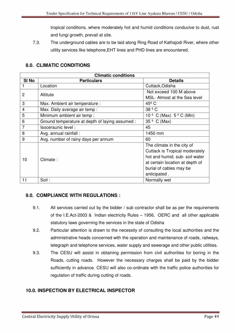
Tender Specification for Technical Requirements of 11kV Line Ayakara Bhawan / CESU / Odisha
Central Electricity Supply Utility of Orissa Page 49
tropical conditions, where moderately hot and humid conditions conducive to dust, rust
and fungi growth, prevail at site.
7.3. The underground cables are to be laid along Ring Road of Kathajodi River, where other
utility services like telephone,EHT lines and PHD lines are encountered.
8.0. CLIMATIC CONDITIONS
Climatic conditions Sl No Particulars Details
1 Location Cuttack,Odisha
2 Altitute Not exceed 100 M above
MSL- Almost at the Sea level
3 Max. Ambient air temperature : 45º C
4 Max. Daily average air temp : 38 º C
5 Minimum ambient air temp : 10 º C (Max) 5 º C (Min)
6 Ground temperature at depth of laying assumed : 35 º C (Max)
7 Isoceraunic level : 45
8 Avg. annual rainfall : 1450 mm
9 Avg. number of rainy days per annum 60
10 Climate :
The climate in the city of
Cuttack is Tropical moderately
hot and humid. sub- soil water
at certain location at depth of
burial of cables may be
anticipated .
11 Soil : Normally wet
9.0. COMPLIANCE WITH REGULATIONS :
9.1. All services carried out by the bidder / sub contractor shall be as per the requirements
of the I.E.Act-2003 & Indian electricity Rules – 1956, OERC and all other applicable
statutory laws governing the services in the state of Odisha
9.2. Particular attention is drawn to the necessity of consulting the local authorities and the
administrative heads concerned with the operation and maintenance of roads, railways,
telegraph and telephone services, water supply and sewerage and other public utilities.
9.3. The CESU will assist in obtaining permission from civil authorities for boring in the
Roads, cutting roads. However the necessary charges shall be paid by the bidder
sufficiently in advance. CESU will also co-ordinate with the traffic police authorities for
regulation of traffic during cutting of roads.
10.0. INSPECTION BY ELECTRICAL INSPECTOR

Tender Specification for Technical Requirements of 11kV Line Ayakara Bhawan / CESU / Odisha
Central Electricity Supply Utility of Orissa Page 50
10.1. All Electrical installations and equipments are to be inspected and approved by the
Chief Electrical Inspector to the Government of Odisha, before commissioning.
10.2. The Contractor will arrange for the payment of the necessary fees for inspection.
10.3. Any defects pointed out by the Electrical Inspector, shall be corrected or attended by
the bidder /subcontractor at his own cost and he shall pay, for subsequent inspection
charges to the Electrical Inspector, for obtaining approval.
11.0. INSTALLATION OF U.G. CABLES
11.1. Method Of Ug Cable Laying : Laying 11 kV HT UG cables at a depth not more than
3 Mtrs, by trenchless technology ,adopting horizontal boring using appropriate standard
machines. Boring & Drawing of cable including preparation at site
11.2. ROUTE PLANS: Tentative cable route plans will be furnished to the contractors,
indicating the roads road crossings, findings by excavating trial holes by the contractor /
sub contractor. The work should be taken upon only after CESU Engineers approve
the final route. The CESU reserves the right to change, alter deviate the route on
technical reasons.
11.3. TRIAL PITS : The bidder shall excavate trial pits, for alignment purpose at
appropriate distance apart as warranted by the local conditions, keep a record of the
findings and close the trial holes properly to avoid hindrance / accidents to pedestrian
traffic. The final route / alignment of the cables shall be decided based on the finding of
the trial holes. 11.4. It is the responsibility of the bidder to maintain as far as possible the required statutory
clearances from other utility services.
11.5. Any damage caused, inadvertently to any utility services shall be the sole responsibility
of the contractor.
12.0. STATUTORY NOTICES AND WAY LEAVES
12.1. The Contractor shall arrange the necessary way leaves from the concerned public
utility authorities and CESU shall give the required assistance to the contractor in
completing the project.
13.0. LAYING OF CABLES
13.1. 11 kV H.T 3 core HT UG cables: Laying 11 kV HT UG cables by trenchless technology by adopting horizontal boring at
a depth not more than 3 Mtrs using appropriate standard machines.
14.0. LAYING OUT THE CABLE :
14.1. 11 kV H.T 3 core HT UG cables:

Tender Specification for Technical Requirements of 11kV Line Ayakara Bhawan / CESU / Odisha
Central Electricity Supply Utility of Orissa Page 51
The cable shall be pulled / drawn smoothly in the bored holes by the horizontal boring
machine itself. The excavated cable trench shall be drained of all water and bed
surface shall be smooth, uniform and fairly hard before laying out the cable. The
cable shall be pulled in the trench only on cable rollers spaced out at uniform
intervals to prevent damage to cable. The laying out process shall be smooth and
steady, without subjecting the cable abnormal tension. The cable laid out shall be
smoothly and evenly transferred to the ground after providing sand cushion and shall
never be dropped. All the snake bends in the cable shall be straightened out.
14.2. Loop Cable : One complete loop of the cable has to be kept at each
termination point.
15.0. FLAKING
15.1. Wherever it is not possible to lay of the entire cable drum length, the cable should be
cut and properly sealed and if it is necessary to remove the cable from the drum, it
should be properly flaked. Such cable lengths should be properly stored at site. 16.0. CABLES AND OVER BRIDGES :
16.1. Wherever the cable route crosses bridges the cable shall be laid in the ducts, if provided,
by removing and replacing the R.C.C. covers and filled with sand cushion. 16.2. In the absence of the cable ducts over bridges, the cable shall be laid in suitable size
steel/G.I. pipes or as directed by the engineer-In-charge and the pipe covered by cement
concrete if necessary to protect from direct sunrays.
17.0. CABLE CROSSING OPEN DRAINS WITH LONG SPAN :
17.1. Wherever the cable to cross open drains with a long span, the cable shall be laid in
suitable size G.I. pipe, properly jointed with suitable collars. The GI pipe shall be firmly
supported on pillars, columns, or suitable support of R.C.C. foundation with stone masonry
in cement mortar 1:4 17.2. Wherever the U.G. cable has to cross the sewerage or water supply line the U.G. cable
has to be taken below them maintaining adequate clearance. Further wherever the U.G.
cable runs parallel to the telephone cable a separation distance of at east 300-mm shall be
maintained. 17.3. The cables shall be laid in stoneware pipe wherever the cable and trench crosses private
roads, gates, etc. In order to avoid inconvenience the stoneware pipe should be laid first
after excavation and excavated trench shall be back filled, compacted and surface properly
redone to restore that original condition.
18.0. CABLE AND JOINT MARKERS

Tender Specification for Technical Requirements of 11kV Line Ayakara Bhawan / CESU / Odisha
Central Electricity Supply Utility of Orissa Page 52
18.1. Permanent means of indicating the positions of joints on site should be provided. During
the course of permanent reinstatement cable and joint markers, should be laid directly
above the route of the cable and the position of the joint respectively. 18.2. Wherever it is not possible to place the marker directly over the cable route or joint the
marker should be suitably placed near the cable route or joint on which the distance of the
cable route or joint at right angles to and parallel to the marker should be clearly indicated. 18.3. The position of fixing the markers will be at the discretion of the Engineer-In-charge.
19.0. JOINTING OF CABLES
19.1. GENERAL: It shall be noted that the U.G. cables are of XLPE insulation and needs
special care in jointing. The cable jointer and his assistant shall have experience in
making joints / terminations. Jointing work should commence as soon as two or three
lengths of cables have been laid. All care should be taken to protect the factory-plumbed
cap/seal by laying the end solid in bitumen until such time as the jointing is commenced.
19.2. Jointing of cables in carriage ways, drives, under costly paving, under concrete or asphalt
surfaces and in proximity to telephone cables and water mains, should be avoided
whenever possible.
19.3. JOINT PITS: The joint pits should be sufficient dimensions as to allow jointers to work with
as much freedom of movement and comfort as cables proposed to be jointed. The sides
of the pit should be draped with tarpaulin sheet to prevent loose earth from falling on the
joint during the course of making. The pit should be well shored with timber, if necessary.
An overlap of about 1.0 mtr of the cables to be jointed may be kept, for allowance to
adjust the position of the joint. When two or more cables are laid together the joints shall
be arranged to be staggered by 2 to 2.5 mtr. 19.4. SUMP PITS: When jointing cables in water logged ground or under monsoon conditions,
a sump pit should be excavated at one end of the joint pit in such a position so that the
accumulating water can be pumped or bailed out by buckets without causing interference
to the jointing operation. 19.5. TENTS: A tent should be used in all circumstances wherever jointing work is carried out in
the open irrespective of the weather conditions. The tent should be so covered as to have
only one entrance and the back facing the direction of the wind. The tent cover should be
properly weighted or tied down on the sides.
19.6. MEASUREMENT OF INSULATION RESISTANCE: Before jointing is commenced the
insulation resistance of both sections of the cable to be jointed should be checked by
insulation resistance testing instrument. An insulation resistance – testing instrument of

Tender Specification for Technical Requirements of 11kV Line Ayakara Bhawan / CESU / Odisha
Central Electricity Supply Utility of Orissa Page 53
2.5/5 kV shall be used. The Insulation Resistance values, between phases and phase to
earth shall be recorded. The actual jointing operation shall start only after the approval of
the engineer in charge of works.
19.7. PRECAUTIONS BEFORE MAKING A JOINT OR CUTTING A CABLE. The cable end seals should not be opened until all necessary precautions have been
taken to prevent circumstances arising out of rainy/inclement weather conditions, which
might become uncontrollable. The cable seals should be examined to ascertain if they are
intact and also that the cable ends are not damaged, if the seals are found broken or the
lead sheath punctured, the cable ends should not be jointed until after due examination
and testing by the engineer-in-charge of the works.
19.8. PRECAUTIONS TO BE TAKEN ON LIVE CABLES IN SERVICE
Sometimes it becomes necessary that a H.V. cable, which is in service, be cut for making
a straight joint with a new cable. In such cases work on joint should start only after the in
service cable is properly identified, isolated, discharged, tested and effectively earthed.
Search coils interrupters or cable-identifying instruments should be used for this purpose.
19.9. IDENTIFICATION NUMBERS / COLOURS AND PHASING : The cables should be laid
and jointed number to number or colour to colour shown on the core identifying marks and
prevent cross jointing. In all cases, the cables should be tested and phased out, and
more particularly so when the cable terminates at Ring Main Unit / Sub-station. 19.10. MAKING A JOINT: The Heat shrinkable joints used shall be conforming to the
specification vide Sec-iv. Alternatively push-on or Tapex or cold shrinkable type can be
used with the approval of CESU. The contractor should furnish all the technical
particulars of these joints and obtain approval only in case they are found superior to the
heat shrinkable joints. Epoxy based joints are not permitted. Comprehensive jointing
instructions obtained from the manufacturer of joint kits shall be meticulously followed.
The connection of the earth wires should be done using flexible bonds connected to cable
sheath using clips or soldering. Aluminum conductor strands shall be joined be joined by
mechanical compression method, using suitable die and sleeve with a good quality tool.
The joints shall conform to specification as per IS 13573-1992.
19.11. TRANSITION JOINTS: Wherever straight through joints will have to be made with
existing cables under the following conditions, the contractor shall arrange such type of
joints and execute them with skilled jointers.
(1) Between cables having two different types of insulation viz., paper and XLPE (2) Between cables having two different types of conductor material, viz. copper
and aluminum.

Tender Specification for Technical Requirements of 11kV Line Ayakara Bhawan / CESU / Odisha
Central Electricity Supply Utility of Orissa Page 54
(3) Or a combination of the above
The transition joints shall conform to IS 13705 – Transition joints for cables for
working voltages from 11 KV upto and including 33 KV – performance
requirements and type tests.
19.12. CABLE TERMINATIONS: Cable terminations required are both indoor and outdoor type
and invariably be of heat shrinkable type conforming to the specifications vide Sec-iv. .
Alternatively push-on or Tapex or cold shrinkable type can be used with the approval of
CESU with appropriate sheds for rainwater in case of outdoor terminations. All the
technical particulars to establish the superiority in the performance of these joints shall be
furnished while seeking approval. The terminations shall conform to specifications as per
IS 13573 – 1992. The instructions furnished by the manufacturer of termination boxes/kits
should strictly be followed.
19.13. Whenever a cable raised from the trench to end in termination, to be finally connected to
an overhead line or transformer, the following instructions should be complied with –
(i) One coil to made and left in the ground for future needs
(ii) The rise of cable, immediately from the ground level should be enclosed in
suitable diameter GI pipe to height of 2 mt.
(iii) The balance portion of the cable should be neatly curved, in ‘S’ shape.
(iv) The cable and pipe should be properly fastened by using appropriate clamps
/support. The hardware of clamps shall be painted with red oxide and
enamel paint or galvanized.
(v) The lugs on the termination shall be compressed with a suitable compression
tool.
20.0. EARTHING AND BONDING
20.1. The metal sheath and Armour should be efficiently bonded and earthed at all terminals
to earth electrodes provided. The cross sectional area of the bond shall be such that the
resistance of each bond connection shall not exceed the combined resistance of an
equal length of the metal sheath and Armour of the cable.
21.0. TESTING AFTER LAYING AND JOINTING
21.1. All cables after laying and jointing works are completed should be tested systematically
and insulation and pressure tests should be made on all underground cables. 21.2. All test results should be recorded in tabular form in logbooks kept for the purpose 21.3. The cable cores should be tested for :-
(i) Continuity (ii) Absence of cross phasing (iii) Insulation resistance to earth; insulation resistance between conductors.

Tender Specification for Technical Requirements of 11kV Line Ayakara Bhawan / CESU / Odisha
Central Electricity Supply Utility of Orissa Page 55
22.0. H.V. TESTS
22.1. After the laying and jointing work is completed, a high voltage test should be applied to
the cable to ensure that the cable has not been damaged during or after the laying
operations and there is not defect in the joining
22.2. The high voltage tests should be as per IS 1255 or as per international standards. The
H.V. testing instruments shall be brought by the turn key contractor.
23.0. TESTING AND RECORD OF CABLE CONSTANTS :
23.1. When the cable is ready, just before commissioning, the cable constants viz, the
resistance, capacitance and inductance of each conductor should be determined and
recorded, along with frequency at which the values of capacitance and inductance are
determined.
24.0. GUARANTEE
24.1. All the cable joints / termination done by the contractor shall be guaranteed for 12
months from the date of energisation of the complete cable. In the event of failure during
the guarantee period, the restoration work shall be done free of cost by the contractor
within 24 hours of giving notice or else the expenditure incurred by CESU to re-do the
joint / termination will be recovered from the performance guarantee amount held with
the CESU.
25.0. CABLE RECORDS 25.1. Accurate neat plans / sketches, drawn to suitable scale (1 cm = 10M) should be
prepared and furnished by the contractor after the completion of each work.
25.2. All relevant information should be collected at site, during the progress of work and
preserved for preparation of drawings.
25.3. The following essential data should be incorporated on all drawings
a) Size, type of cable or cables.
b) Location of the cable in relation to prominent land mark property, Kerb-line etc., with
depths.
c) The cross section showing where cables are laid in piper or ducts, giving their sizes,
type and depths.
d) Position and type of all joints
e) Location of other cables which run alongside or across the cable route.
f) Position and depths of all pipers, ducts, etc., which are met as obstruction to the
cable route.
g) Accurate lengths from joint to joint
h) Manufacturers name and drum number of the cable, between sections / joint to joint.

Tender Specification for Technical Requirements of 11kV Line Ayakara Bhawan / CESU / Odisha
Central Electricity Supply Utility of Orissa Page 56
Two transparencies and six blue print copies of the cable records prepared as above shall be given to the CESU’s engineer as a part of the contract as soon as the cable is charged.
Section-VI
Lightning Arrestor

Tender Specification for Technical Requirements of 11kV Line Ayakara Bhawan / CESU / Odisha
Central Electricity Supply Utility of Orissa Page 57
TECHNICAL SPECIFICATION OF 11 KV LIGHTNING ARRESTOR
(VOLTAGE CLASS SURGE ARRESTORS)
The specification covers the design, manufacture, shop & laboratory testing before
despatch, supply delivery of 11 KV, Station class heavy duty, gapless metal oxide Surge
Arrestors, insulating base, clamps, complete fittings & accessories suitable for 33 KV
transformers/feeders including arrester's electrode earthing.
1.0 STANDARDS
The design, manufacture and performance of Surge Arrestors shall comply with IS: 3070
Part-3 and other specific requirement stipulated in the specification Unless otherwise,
specified, the equipment, material and processes shall conform to the latest applicable
Indian/International Standards as listed hereunder:
IS: 2071-1993 (Part-1) : Methods of High Voltage Testing General Definitions & Test Requirements.
IS: 2071-1974 (Part-2) : Test Procedures
IS: 2633-1986 : Methods for Testing uniformity of zinc coated Articles.
IS: 3070-1993 (Part-3) : Specification for surge arrestor for alternating current system Metal-Oxide lightening Arrestors without gaps.

Tender Specification for Technical Requirements of 11kV Line Ayakara Bhawan / CESU / Odisha
Central Electricity Supply Utility of Orissa Page 58
IS:4759-1996 : Specification for hot dip zinc coating on Structural Steel and other allied products.
IS: 5621-1980 : Hollow Insulators for use in Electrical Equipment.
IS: 6209-1982 : Methods of Partial discharge measurement.
IS: 6745-1980 : Methods for determination of mass of zinc coating on zinc coated iron and steel articles.
IEC:TC-37 : Test Procedures.
ANSI/IEEE-C.62.11(1982) : Metal Oxide, Surge Arrestor for A.C. Power Circuits.
IEE-99-4 : Surge Arrestors.
The equipment complying with any other internationally accepted standards shall also be
considered if it ensures performance equivalent to or superior to the India Standards.
2.0 GENERAL REQUIREMENT
2.1 The Metal Oxide gap less Surge Arrestor without any series or shunt gap shall be suitable for
protection of UG cable, associated equipment from voltage surges resulting from natural
disturbance like lightening as well as system disturbances.
2.2 The surge arrestor shall draw negligible current at operating voltage and at the same time
offer least resistance during the flow of surge current.
2.3 The surge arrestor shall consist of non-linear resistor elements placed in series and housed
in electrical grade porcelain housing/silicon polymeric of specified creepage distance.
2.4 The assembly shall be hermetically sealed with suitable rubber gaskets with effective sealing
system arrangement to prevent ingress of moisture.
2.5 The surge arrestor shall be provided with line suitable for cable for vertical and horizontal
take off. The earth terminals shall be provided of suitable size. The groundside terminal of
surge arrestor shall be connected with 50x6mm- galvanized strip, one end connected to
the surge arrestor and second end to a separate ground electrode (Electrode type of
earthing). The contractor shall also recommend the procedure which shall be followed in
providing the ear thing/system to the Surge Arrestor.
2.6 The surge arrestor shall not operate under power frequency and temporary over voltage
conditions but under surge conditions, the surge arrestor shall change over to the conducting
mode.
2.7 Surge arrestor shall have a suitable pressure relief system to avoid damage to
the porcelain/silicon polymeric housing and providing path for flow of rated fault currents
in the event of arrestor failure.
2.8 The reference current of the arrestor shall be high enough to eliminate the influence of
grading and stray capacitance on the measured reference voltage.

Tender Specification for Technical Requirements of 11kV Line Ayakara Bhawan / CESU / Odisha
Central Electricity Supply Utility of Orissa Page 59
2.9 The surge arrestor shall be thermally stable and the contractor shall furnish a copy of thermal
stability test with the bid.
2.10 The arrestors for 11 KV system shall be suitable for mounting on transformers as well as in
the yard. The supplier shall furnish the drawing indicating the dimensions, weight etc. of the
surge arrestors for the design of mounting brackets.
2.11 The arrestor shall be capable of handling terminal energy for high surges, external pollution
and transient over voltage and have low losses at operating voltage.
3.0 ARRESTOR HOUSING
3.1 The arrestor housing shall be made up of porcelain/silicon polymeric housing and shall be
homogenous, free from laminations, cavities and other flaws of imperfections that might
affect the mechanical and dielectric quality. The housing shall be uniform brown colour, free
from blisters, burrs and other similar defects.
Arrestors shall be complete with insulating cases, fasteners for stacking units together and
terminal connectors.
3.2 The housing shall be so coordinated that external flashover shall not occur due to application
of any impulse or switching surge voltage upto the maximum design value for arrestor. The
arrestors shall not fail due to contamination. The 11KV arrestors housing shall be designed
for pressure relief class as given in Technical Parameters of the specification.
3.3 Sealed housing shall exhibit no measurable leakage.
4.0 TESTS
4.1 Test on Surge Arrestors
The Surge Arrestors offered shall be type tested not earlier than 5 years before the date of
opening of this tender. The surge arrestors shall be subjected to routine and acceptance
tests in accordance with IS: 3070(Part3)-1993. In addition, the suitability of the Surge
Arrestors shall also be established for the following:
* Residual voltage test
* Reference voltage test
* Leakage current at M.C.O.V.
* P.D. Test
* Sealing test
* Thermal stability test
* Aging and Energy capability test
* Watt loss test
Each metal oxide block shall be tested for guaranteed specific energy capability in addition to
routine/acceptance test as per IEC/IS.
4.2 The maximum residual voltages corresponding to nominal discharge current of 10KA for
steep current, impulse residual voltage test, lightning impulse protection level and switching
impulse level shall generally conform to Annexure-K of IEC-99-4.
4.3 The bidder shall furnish the copies of the type tests and the characteristics curves
between the residual voltage and nominal discharge current of the offered surge arrestor and

Tender Specification for Technical Requirements of 11kV Line Ayakara Bhawan / CESU / Odisha
Central Electricity Supply Utility of Orissa Page 60
power frequency voltage V/s time characteristic of the surge arrestor subsequent to impulse
energy consumption as per clause 6.6 of IS: 3070 (Part-3) offered along with the bid.
4.4 The surge arrestors housing shall also be type tested and shall be subjected to routine
and acceptance tests in accordance with IS: 2071.
4.5 Galvanization Test
All Ferrous parts exposed to atmospheric condition shall have passed the type test and be
subjected to routine and acceptance test in accordance with IS: 2633 & IS: 6745.
5.0 NAME PLATE
5.1 The nameplate attached to the arrestors shall carry the following information: -
* Manufacturing Trade Mark
* Year of Manufacture
* Rated Voltage
* Continuous Operation Voltage
* Pressure relief rated current
* Name of Client-
* Purchase Order Number along with date.
6.0 INSPECTION
6.1 All tests and inspection shall be made in the manufacturer’s works unless
otherwise specifically agreed upon by the manufacturer and purchaser at the time of
placement of purchase order. The manufacturer shall afford to the inspector representing the
purchaser, al reasonable facilities, without charge to satisfy him that the material being
furnished is in accordance with these specifications. The purchaser reserves the right to get
an component/material being used by the manufacturer of the Surge Arrestor tested from
any recognized test house.
6.2 The inspection by the purchaser or his authorized representative shall not relieve
the contractor of his obligation of furnishing equipment in accordance with the specifications.
7.0 DRAWING AND INSTRUCTION MANUALS
Within 15 days of receipt of the order, the successful tenderer shall furnish to the
purchaser the following drawings and literature for approval:
a. Outline dimensional drawings of Surge Arrestor and all accessories. b.
Assembly drawings and weights of main component parts.
c. Instructions manual
d. Drawing showing details of pressure relief value
e. Volt-time characteristics of surge arrestors.
f. Detailed dimensional drawing of porcelain housing/ Silicon polymeric
i.e. internal diameter, external diameter, thickness, height profile,

Tender Specification for Technical Requirements of 11kV Line Ayakara Bhawan / CESU / Odisha
Central Electricity Supply Utility of Orissa Page 61
creepage distance, dry arching distance etc.
GURANTEED TECHNICAL PARTICULARS FOR
11 KV LIGHTNING ARRESTOR
(To be submitted along with offer)
Sl. No. Particulars Bidder’s Offer
1. Name of manufacturer.
2. Type Designation
3. Model (Drawing No.)
4. Applicable Standard
5. No. of units per Arrestors
6. Rated Voltage
7. Nominal discharge current 8/20
micro second wave (KA)
8. Maximum continuous operating Voltage
9. Insulation withstand voltage
power frequency.
10. Maximum Lightning Impulse
Residual voltage (8/20 micro
second wave

Tender Specification for Technical Requirements of 11kV Line Ayakara Bhawan / CESU / Odisha
Central Electricity Supply Utility of Orissa Page 62
11. Maximum steep current Impulse Residual voltage at 10 KA of micro second front time.
12. Maximum Switching Impulse Residual voltage 50 x 100 micro seconds at 500 Amps.
13. Current Impulse withstand capability.
i) Long duration discharge class.
ii) Minimum energy discharge capability
14. Protective Ratio
15. High current impulse withstand value (4 x10 Micro seconds)
16. Pressure relief class.
i) High current
ii) Low current
17. Reference current of the arresters Ambient
18. Current at M.C.O.V. (Maximum Continuous
i) Resistive Current IR
ii) Capacitive voltage IC
19. Temporary over voltage capability
i) 0.1 second
ii) 1.0 Second
iii) 10.0 Second
iv) 100 second
20 a) Total Creepage Distance
b) Protected Creepage Distance
21. Over all dimensions
i) Height
ii) Diameter
22. Cantilever strength KG-M
23. Mounting flange dimensions
24 Minimum Clearance
i) Between Arrestors
ii) Arrestor and adjoining - objects
Tender Specification for Technical Requirements of 11kV Line Ayakara Bhawan / CESU / Odisha
Central Electricity Supply Utility of Orissa Page 63
Section-VII
11kV AB Switch

Tender Specification for Technical Requirements of 11kV Line Ayakara Bhawan / CESU / Odisha
Central Electricity Supply Utility of Orissa Page 64
TECHNICAL SPECIFICATIONS FOR 11kV AB Switch
1.0 SCOPE:-
This specification provides for manufacture, testing at works and delivery For supply of
11KV AB switches. The 11KV AB switches shall conform to IS: 9920 (Part-I to IV)
2.0 AB SWITCHES:-
The 11KV Air Break Switches are required with two poles in each phase. The AB Switches
shall be supplied complete with phase coupling shaft, operating rod and operating handle. It
shall be manually gang operated and vertically break and horizontal mounting type.
2.0.1 The AB Switch shall be designed for a normal current rating of 400 Amps and for continuous
service at the system voltage specified as under:
11 KV AB Switch: 11KV + 10% continuous 50 C/s solidly grounded earthed neutral system.
The length of break in the air shall not be less than 400 mm for 11KV AB Switches.
2.0.2 The 11KV AB Switches are required with post insulators. The AB switches should be suitable
for mounting on the structure. The mounting structure will be arranged by the purchaser
separately. However, the AB Switches shall be supplied with base channel for mounting on
the structure which will be provided by the purchaser. The phase to phase spacing shall be
750mm in case of 11KV AB Switches.
3.0 POST INSULATORS:-
The complete set of three phase AB Switches shall have post insulators.
11KV AB Switches : 11KV Post Insulators

Tender Specification for Technical Requirements of 11kV Line Ayakara Bhawan / CESU / Odisha
Central Electricity Supply Utility of Orissa Page 65
The post insulators should conform to the latest applicable Indian standards IS: 2544
Specification for Porcelain Post insulator Polycon or of compact solid core or long rod
insulators are also acceptable. Creepage distance should be adequate for highly polluted
outdoor atmosphere in open atmosphere. The porcelain used for manufacture of AB
Switches should be homogeneous free from flaws or imperfections that might affect the
mechanical dielectric quality. They shall be thoroughly vitrified, tough and impervious to
moisture. The glazing of the porcelain shall be of uniform brown in colour, free from blisters,
burns and other similar defects. Insulators of the same rating and type shall be
interchangeable.
The porcelain and metal parts shall be assembled in such a manner that any thermal
expansion differential between the metal and porcelain parts through the range of
temperature variation shall not loose the parts or create undue internal stresses which may
affect the electrical or mechanical strength. Cap and base of the insulators shall be
interchangeable with each other. The cap and base shall be properly cemented with
insulators to give perfect grip. Excess cementing must be avoided.
The tenderers shall in variably enclose with the offer, the type test certificate from NABL
accredited testing laboratory and other relevant technical guaranteed particulars of insulators
offered by them. Please note that AB Swiches without type test certificates will not be
accepted.
4.0 Each 11KV Post Insulators should have technical particulars as detailed below:
11 KV
i Nominal system voltage kV (rms) 11
ii Highest system voltage kV (rms.) 12
iii Dry Power Frequency one kV minute withstand voltage (rms) in 35
iv Wet Power frequency one minute withstand voltage (rms) in KV 35
v Power Frequency puncture kV (rms) voltage
1.3 times the actual dry flashover voltage
vi Impulse withstand voltage kV (Peak) 75
vii Visible discharge voltage kV (rms) 9
viii Creepage distance in mm (minimum) 320
5.0 The rated insulation level of the AB Switches shall not be lower than the values specified below:-
Sl. No
Standard
declared voltage
Rated Voltage
of the AB Switches
Standard impulse with stand voltage (positive & negative polarity KV
(Peak)
One Minute power frequency withstand voltage kV (rms)
Across the
Isolating distance
To earth &
between poles
Across
the Isolating distance
To earth & between
poles

Tender Specification for Technical Requirements of 11kV Line Ayakara Bhawan / CESU / Odisha
Central Electricity Supply Utility of Orissa Page 66
i 11KV 12KV 85KV 75KV 32KV 28KV
6.0 TEMPERATURE RISE:-
The maximum temperature attained by any part of the equipment when in service at site
under continuous full load conditions and exposed to the direct rays of Sun shall not exceed
45 degree above ambient.
7.0 MAIN CONTACTS:-
AB Switches shall have heavy duty self-aligning type contacts made of hard drawn
electrolytic copper/brass. The various parts should be accordingly finished to ensure inter
changeability of similar components. The moving contacts of the switch shall be made from
hard drawn electrolytic copper brass. This contact shall have dimensions as per drawing
attached so as to withstand safely the highest short-circuit currents and over voltage that
may be encountered during service. The surface of the contact shall be rounded smooth and
silver-plated. In nut shell the male and female contact assemblies shall ensure.
(i) Electro-dynamic withstands ability during short circuits without any risk of
repulsion of contacts. (ii) Thermal withstands ability during short circuits.
(iii) Constant contact pressure even when the lower parts of the insulator stacks are subjected to tensile stresses due to linear expansion of connected bus bar of flexible conductors either because of temperature variations or strong winds.
(iv) Wiping action during closing and opening. (v) Fault alignment assuring closing of the switch without minute adjustments.
8.0 CONNECTORS:-
The connectors shall be made of hard drawn electrolytic copper or brass suitable for
Raccoon/Dog ACSR conductor for both 11KV AB Switches. The connector should be 4 -bolt
type.
9.0 OPERATING MECHANISM:-
All AB Switches shall have separate independent manual operation. They should be provided
with ON/OFF indicators and padlocking arrangements for locking in both the end positions to
avoid unintentional operation. The isolating distances should also be visible for the AB
Switches.
The AB Switch will be supplied with following accessories:
Sr. No
Item Size of 11KV AB Switch
i
Operating Rod (GI dia) Length 5.50 meter dia 25 mm
ii
Phase coupling square rod (GI) Length 1800 mm Size 25x25 mm
iii Hot dip galvanized Operating handle (GI) 1 No.
The AB Switches shall be capable to resist any chance of opening out when in closed
position. The operating Mechanism should be of robust constructions, easy to operate by
single person and to be located conveniently for local operation in the switchyard. The GI
pipe shall conform to ISS: 1239-68 and the vertical down rod should be provided with
adequate joint in the mid section to avoid bending or buckling. Additional leverage should be

Tender Specification for Technical Requirements of 11kV Line Ayakara Bhawan / CESU / Odisha
Central Electricity Supply Utility of Orissa Page 67
provided to maintain mechanical force with minimum efforts.
All iron parts should be hot dip galvanized. All brass parts should be silver plated and all nuts
and bolts should be hot dip galvanized.
10.0 ARCING HORNS:-
It shall be simple and replaceable type. They should be capable of interrupting line- charging
current. They shall be of first make and after break type.
11.0 BUSH:-
The design and construction of bush shall embody all the features required to withstand
climatic conditions specified so as to ensure dependable and effective operations
specified even after long periods of inaction of these Air Break Switches. They shall be made
from highly polished Bronze metal with adequate provision for periodic lubrication through
nipples and vent.
12.0 DESIGN, MATERIALS AND WORKMANSHIP:-
The successful tenderers shall assume full responsibility for co-ordination and adequate
design.
All materials used in the construction of the equipment shall be of the appropriate class, well
finished and of approved design and material. All similar parts should be accurately finished
and interchangeable.
Special attention shall be paid to tropical treatment to all the equipment, as it will be
subjected during service to extremely severe exposure to atmospheric moisture and to long
period of high ambient temperature. All current carrying parts shall be of non- ferrous metal
or alloys and shall be designed to limit sharp points/edges and similar sharp faces.
The firm should submit the following type test certificate along with the certified copy of the
drawing (from NABL Testing Lab). The type test should be from NABL accredited testing
laboratory & should not be older than 5 years from the date of opening of tender.
1. Test to prove capability of rated peak short circuit current and the rated short time current. The rated short time current should correspond to minimum of 10K Amp and the peak short circuit current should correspond to minimum of 25K Amps.
2. Lightning impulse voltage test with positive & negative polarity. 3. Power Frequency voltage dry test and wet test 4. Temperature rise test 5. Mill volt drop tests
13.0 Dimension of 11KV AB Switches in (Max.) Tolerance 5%.
Sr. Particulars 11KV AB Switch
i
Drawing No. EB/P-6/MPSEB/7 (revised)
dated 01.05.88 ii MS Channel 450x75x40
iii Creepage distance of
Post Insulator
320mm (Min)
iv Highest of Port shell 254 mm v Fixed contact assembly
i) Base 165x36x8
ii) Contact 70x30x6

Tender Specification for Technical Requirements of 11kV Line Ayakara Bhawan / CESU / Odisha
Central Electricity Supply Utility of Orissa Page 68
iii) GI cover 110x44
Spring 6 Nos. vi Moving contract assemble i Base Assembly 135x25x8 ii Moving 180x25x9 iii Bush Bronze Metal iv Thickness of Grooves 7
14.0 CONNECTORS:-
i Connector
(diamentions of each pad) 60x50x8
(Moving & fix both) 60x50x8
(Moving & fix both)
The bidder should provide AB Switches with terminal connectors, set of insulators,
mechanical inter works and arcing horns sets. The base channel for the mounting of AB
Switches shall also be included in the scope of AB Switches. The operating mechanisms
together with down pipe operating handle etc. are also included in the scope of supply.
15.0 ROUTINE TEST CERTIFICATE : -
The Routine test certificate should invariably be submitted in duplicate of each lot offered for
inspection as per ISS: 9920 (part-I to IV). The offers received without Routine test certificate
shall not be entertained.
16.0 ACCEPTANCE TEST : -
At the time of inspection following test shall be carried out: -
a. Physical verification and measurement of dimension.
b. Power frequency high voltage test.
c. Temperature rise test.
d. Mechanical endurance test / operation test.
e. Milli volt drop test.
f. Galvanising test as per ISS: 2633.
17.0 NAME PLATE: -
The name plate in the following design shall be fixed on each AB Switch.
i) Name of supplier :
ii) Name of purchaser : iii) Order No. and date : iv) Rating : v) serial number of unit :
The size of name plate shall be 2” x 1” for 11 kV AB Switch.

Tender Specification for Technical Requirements of 11kV Line Ayakara Bhawan / CESU / Odisha
Central Electricity Supply Utility of Orissa Page 69
Schedule of Guaranteed Technical Particulars for 11 KV AB Switches
No
Particulars
Requirement
To be specified by
the Bidder
1 Type / make To be indicated 2 Maximum permission continuous service
voltage (KV)
12 KV
3 Length of the Break/Phase (Min.) 400 mm 4 Phase to Phase Spacing 750 mm 5 Power Frequency withstand test voltage for
completely assembled switches
A) Against ground i Dry KV 28 KV
ii Wet KV 28 KV B) Across open contact
i Dry KV 32 KV ii Wet KV 32 KV
C) Between Phases i Dry KV 28 KV
ii Wet KV 28 KV

Tender Specification for Technical Requirements of 11kV Line Ayakara Bhawan / CESU / Odisha
Central Electricity Supply Utility of Orissa Page 70
6 Impulse withstand test voltage of completely
assembled switch without arcing horns with
1.2/50 micro second impulse wave KV (Peak)
85 KV
7 100% impulse flashover voltage of completely
assembled switch with arcing horns with
1.2/50 micro second impulse wave KV (Peak)
85 KV
8 Particulars of the main contacts i.e. fixed
contacts and moving contacts
a Type Spring loaded fixed &
knife type moving
contacts
b Material Hard drawn electrolytic
copper alloy
c Surface Treatment & Thickness of Silver
Coating Silver plated of thickness
of 5 micron
d Contact Pressure 25 KG 9 Continuous Current Rating, Amps 400 amps
10 Short Time Current Rating KA (rms) min. for
1 sec
16 KA
11 Rated Peak Short Circuit Current (KA Peak) 25 KA 12 No. of operations which the switch can
withstand without deterioration of contacts
2000
13 Type of Mounting Horizontal up right
mounting
14 Type & Material used in connector Brass/ Bronze strips 15 Location and Type of Bushing Bush bearing at rotating
insulator
16 Particulars of Post Insulators
i Make( ISI make) To be indicated
ii Type 11 KV Post insulator
type
iii Strength 10 KN
iv Weight 5 Kg (approx.) / unit
v No. of units per stack One
vi Height of stack mm 254 mm
viii Creepage distance mm 320 mm
ix One Minute Power Frequency Dry withstand
voltage KV (rms)
65 KV
x Power Frequency Flashover voltage KV (rms) 70 KV
xi Impulse flashover voltage KV (Peak) 85 KV
xii Impulse withstand voltage KV (Peak) 80 KV (peak)
xiii Puncture voltage (KV) 105 KV

Tender Specification for Technical Requirements of 11kV Line Ayakara Bhawan / CESU / Odisha
Central Electricity Supply Utility of Orissa Page 71

Tender Specification for Technical Requirements of 11kV Line Ayakara Bhawan / CESU / Odisha
Central Electricity Supply Utility of Orissa Page 72
Section-VIII
Proposed Route Map

Proposed 11kV UG Cable From Sishubawan 33/11kV S/S to Ayakar Bhawan near Shelter Chhaka
Shelter
Chhaka Proposed 11kV
XLPE UG Cable
Ayakar
Bhawan
Sishubhawan
33/11kV Sub-Station
CDA
Chhaka
Corporate
Bhawan Ram
ABIT Mandir
College Kathajodi River
Bidanasi
220/132/33kV
Grid S/S
Proposed 11kV UG Cable From Sishubawan
33/11kV S/S to
Ayakar Bhawan near Shelter Chhaka
DWG No: - 01
Client CENTRAL ELECTRICITY SUPPLY UTILITY OF ORISSA
Regd. Office: 2nd Floor, IDCO TOWER
Janpath, Bhubaneswar -751022

Tender Specification for Technical Requirements of 11kV Line Ayakara Bhawan / CESU / Odisha
Central Electricity Supply Utility of Orissa Page 74