Embed Size (px)
Citation preview
Updated Seismic Design Guidelinesfor Model Building Code of Mexico
Arturo Tena-Colunga,a)M.EERI, Ulises Mena-Hernández,b)
Luis Eduardo Pérez-Rocha,b) Javier Avilés,c) Mario Ordaz,d)
and Jorge Iván Vilarb)
The Manual of Civil Structures (MOC), a model design code in Mexico,has been in the process of being updated, and the new version of this code waspublished in 2008. A major update from the 1993 version was performed in thechapter for the seismic design of building structures. This paper summarizesthe most relevant changes of this building code and their relation to researchefforts conducted within Mexico and worldwide to improve the seismic designof building structures. One goal is to make the guidelines as transparent aspossible to users, so that the design process will be clearer to structuralengineers. �DOI: 10.1193/1.3240413�
INTRODUCTION
The previous version of the Manual of Civil Structures (MOC) was published in1993 (MOC-93 1993, Tena-Colunga 1999), so an in-depth review was mandatory in or-der to update the document for 2008. Like ASCE-7 (2005), MOC-2008 (2008) is a verycomprehensive code that specifically addresses the design of several structural systems(buildings, bridges, dams, power stations, industrial facilities, chimneys, silos, pipelines,tanks and deposits, vessels, inverted pendulums, retaining walls, etc.) to such hazards asearthquakes and winds. Modern technologies, such as base isolation and passive energydissipation, are now addressed, along with the use of modern materials like carbon fibersand composites. Specialized topics, including soil-structure interaction, the monitoringof structures, and the evaluation and rehabilitation of existing structures, are alsocovered.
The following sections summarize only some of the most important updated provi-sions that affect the seismic design of building structures. Some background in the basesand design philosophy of the previous seismic provisions of the MOC-93 code in Eng-lish can be found elsewhere (Tena-Colunga 1999).
SEISMIC ZONATION
One of the major changes in the MOC-2008 with respect to previous MOC-93 codeis the concept of the seismic zonation. In the MOC-93 code, Mexico was divided into
a) Departamento de Materiales, Universidad Autónoma Metropolitana, Av. San Pablo # 180, 02200 México, DFb) Instituto de Investigaciones Eléctricas, Calle Reforma 113, Col. Palmira, 62490 Cuernavaca, MEXICOc) Instituto Mexicano de Tecnologa del Agua, Paseo Cuauhnahuac 8532, 62550 Jiutepec, MEXICOd)
Departamento de Sismología, Instituto de Ingeniería, UNAM, Ciudad Universitaria, 04510 México, DF869Earthquake Spectra, Volume 25, No. 4, pages 869–898, November 2009; © 2009, Earthquake Engineering Research Institute
870 TENA-COLUNGA ET AL.
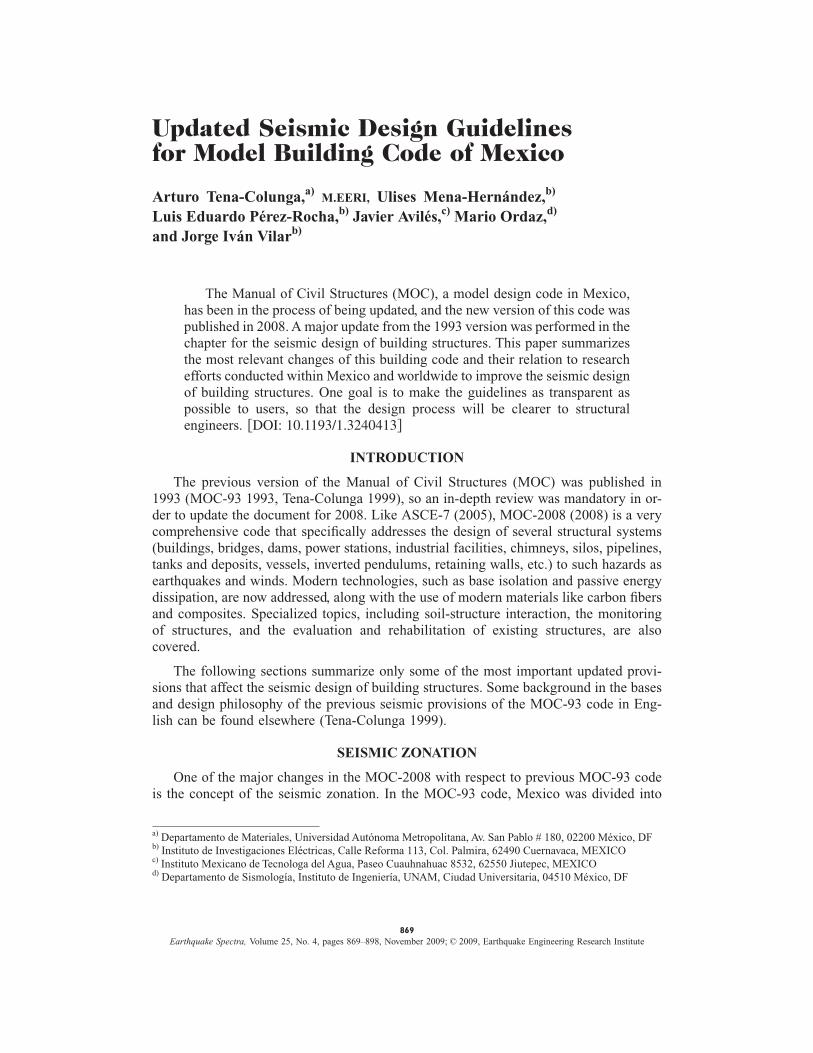
four seismic zones (A, B, C, and D; Figure 1), for which there were three different soilprofile types: I (firm soils), II (“transition” soils), and III (soft soils), as explained ingreater detail elsewhere (MOC-93 1993, Tena-Colunga 1999).
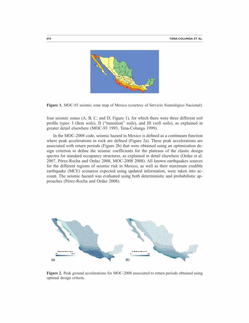
In the MOC-2008 code, seismic hazard in Mexico is defined as a continuum functionwhere peak accelerations in rock are defined (Figure 2a). These peak accelerations areassociated with return periods (Figure 2b) that were obtained using an optimization de-sign criterion to define the seismic coefficients for the plateaus of the elastic designspectra for standard occupancy structures, as explained in detail elsewhere (Ordaz et al.2007, Pérez-Rocha and Ordaz 2008, MOC-2008 2008). All known earthquakes sourcesfor the different regions of seismic risk in Mexico, as well as their maximum credibleearthquake (MCE) scenarios expected using updated information, were taken into ac-count. The seismic hazard was evaluated using both deterministic and probabilistic ap-proaches (Pérez-Rocha and Ordaz 2008).
Figure 1. MOC-93 seismic zone map of Mexico (courtesy of Servicio Sismológico Nacional).
Figure 2. Peak ground accelerations for MOC-2008 associated to return periods obtained using
optimal design criteria.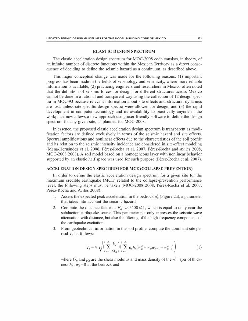
UPDATED SEISMIC DESIGN GUIDELINES FOR THE MODEL BUILDING CODE OF MEXICO 871
ELASTIC DESIGN SPECTRUM
The elastic acceleration design spectrum for MOC-2008 code consists, in theory, ofan infinite number of discrete functions within the Mexican Territory as a direct conse-quence of deciding to define the seismic hazard as a continuum, as described above.
This major conceptual change was made for the following reasons: (1) importantprogress has been made in the fields of seismology and seismicity, where more reliableinformation is available, (2) practicing engineers and researchers in Mexico often notedthat the definition of seismic forces for design for different structures across Mexicocannot be done in a rational and transparent way using the collection of 12 design spec-tra in MOC-93 because relevant information about site effects and structural dynamicsare lost, unless site-specific design spectra were allowed for design, and (3) the rapiddevelopment in computer technology and its availability to practically anyone in theworkplace now allows a new approach using user-friendly software to define the designspectrum for any given site, as planned for MOC-2008.
In essence, the proposed elastic acceleration design spectrum is transparent as modi-fication factors are defined exclusively in terms of the seismic hazard and site effects.Spectral amplifications and nonlinear effects due to the characteristics of the soil profileand its relation to the seismic intensity incidence are considered in site-effect modeling(Mena-Hernández et al. 2006, Pérez-Rocha et al. 2007, Pérez-Rocha and Avilés 2008,MOC-2008 2008). A soil model based on a homogeneous layer with nonlinear behaviorsupported by an elastic half space was used for such purpose (Pérez-Rocha et al. 2007).
ACCELERATION DESIGN SPECTRUM FOR MCE (COLLAPSE PREVENTION)
In order to define the elastic acceleration design spectrum for a given site for themaximum credible earthquake (MCE) related to the collapse-prevention performancelevel, the following steps must be taken (MOC-2008 2008, Pérez-Rocha et al. 2007,Pérez-Rocha and Avilés 2008):
1. Assess the expected peak acceleration in the bedrock a0r (Figure 2a), a parameter
that takes into account the seismic hazard.
2. Compute the distance factor as Fd=a0r /400�1, which is equal to unity near the
subduction earthquake source. This parameter not only expresses the seismic waveattenuation with distance, but also the filtering of the high-frequency components ofthe earthquake excitation.
3. From geotechnical information in the soil profile, compute the dominant site pe-riod Ts as follows:
Ts = 4���n=1
Nhn
Gn���
n=1
N
�nhn�wn2 + wnwn−1 + wn−1
2 �� �1�
where Gn and �n are the shear modulus and mass density of the nth layer of thick-ness hn; wo=0 at the bedrock and
872 TENA-COLUNGA ET AL.
wn =�i=1
n hi/Gi
�i=1N hi/Gi
; n = 1,2, . . . ,N �2�
is a static approximation for the fundamental mode of soil vibration. With Ts
known, the effective shear-wave velocity Vs=4Hs /Ts is computed over a depthHs of at least 30 m. This novel approach is found to yield more accurate resultsthan those obtained by using the average shear-wave velocity of surficial soils,which ignores the sequence of the layers in the soil deposit.
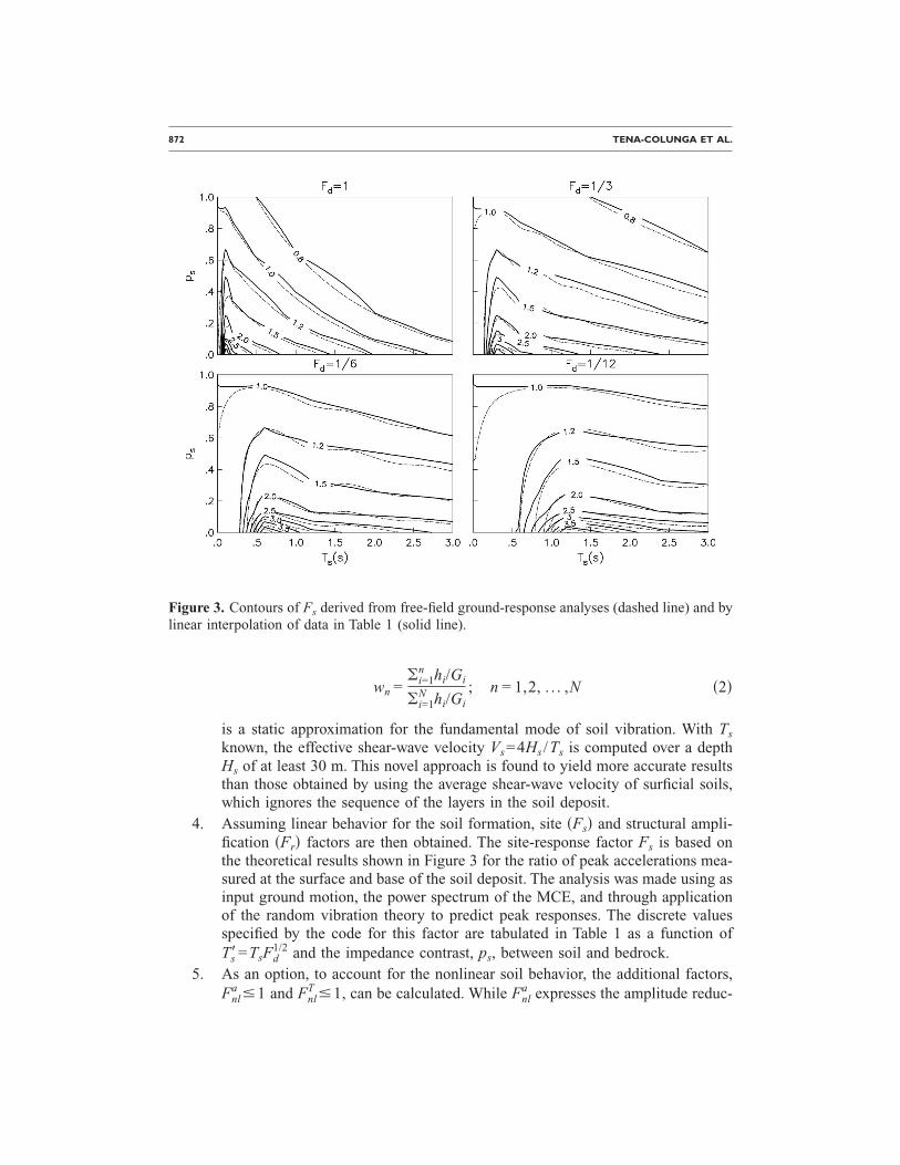
4. Assuming linear behavior for the soil formation, site �Fs� and structural ampli-fication �Fr� factors are then obtained. The site-response factor Fs is based onthe theoretical results shown in Figure 3 for the ratio of peak accelerations mea-sured at the surface and base of the soil deposit. The analysis was made using asinput ground motion, the power spectrum of the MCE, and through applicationof the random vibration theory to predict peak responses. The discrete valuesspecified by the code for this factor are tabulated in Table 1 as a function ofTs�=TsFd
1/2 and the impedance contrast, ps, between soil and bedrock.5. As an option, to account for the nonlinear soil behavior, the additional factors,
Fnla �1 and Fnl
T �1, can be calculated. While Fnla expresses the amplitude reduc-
Figure 3. Contours of Fs derived from free-field ground-response analyses (dashed line) and bylinear interpolation of data in Table 1 (solid line).
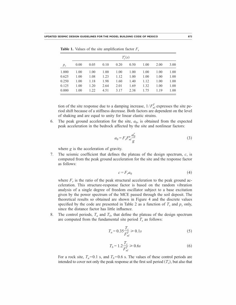
UPDATED SEISMIC DESIGN GUIDELINES FOR THE MODEL BUILDING CODE OF MEXICO 873
tion of the site response due to a damping increase, 1 /FnlT expresses the site pe-
riod shift because of a stiffness decrease. Both factors are dependent on the levelof shaking and are equal to unity for linear elastic strains.
6. The peak ground acceleration for the site, a0, is obtained from the expectedpeak acceleration in the bedrock affected by the site and nonlinear factors:
a0 = FsFnla a0
r
g�3�
where g is the acceleration of gravity.7. The seismic coefficient that defines the plateau of the design spectrum, c, is
computed from the peak ground acceleration for the site and the response factoras follows:
c = Fra0 �4�
where Fr is the ratio of the peak structural acceleration to the peak ground ac-celeration. This structure-response factor is based on the random vibrationanalysis of a single degree of freedom oscillator subject to a base excitationgiven by the power spectrum of the MCE passed through the soil deposit. Thetheoretical results so obtained are shown in Figure 4 and the discrete valuesspecified by the code are presented in Table 2 as a function of Ts and ps only,since the distance factor has little influence.
8. The control periods, Ta and Tb, that define the plateau of the design spectrumare computed from the fundamental site period Ts as follows:
Ta = 0.35Ts
FnlT � 0.1s �5�
Tb = 1.2Ts
FnlT � 0.6s �6�
For a rock site, Ta=0.1 s, and Tb=0.6 s. The values of these control periods areintended to cover not only the peak response at the first soil period �T �, but also that
Table 1. Values of the site amplification factor Fs
ps
Ts��s�
0.00 0.05 0.10 0.20 0.50 1.00 2.00 3.00
1.000 1.00 1.00 1.00 1.00 1.00 1.00 1.00 1.000.625 1.00 1.08 1.23 1.12 1.00 1.00 1.00 1.000.250 1.00 1.18 1.98 1.60 1.40 1.12 1.00 1.000.125 1.00 1.20 2.64 2.01 1.69 1.32 1.00 1.000.000 1.00 1.22 4.51 3.17 2.38 1.75 1.19 1.00
s
874 TENA-COLUNGA ET AL.
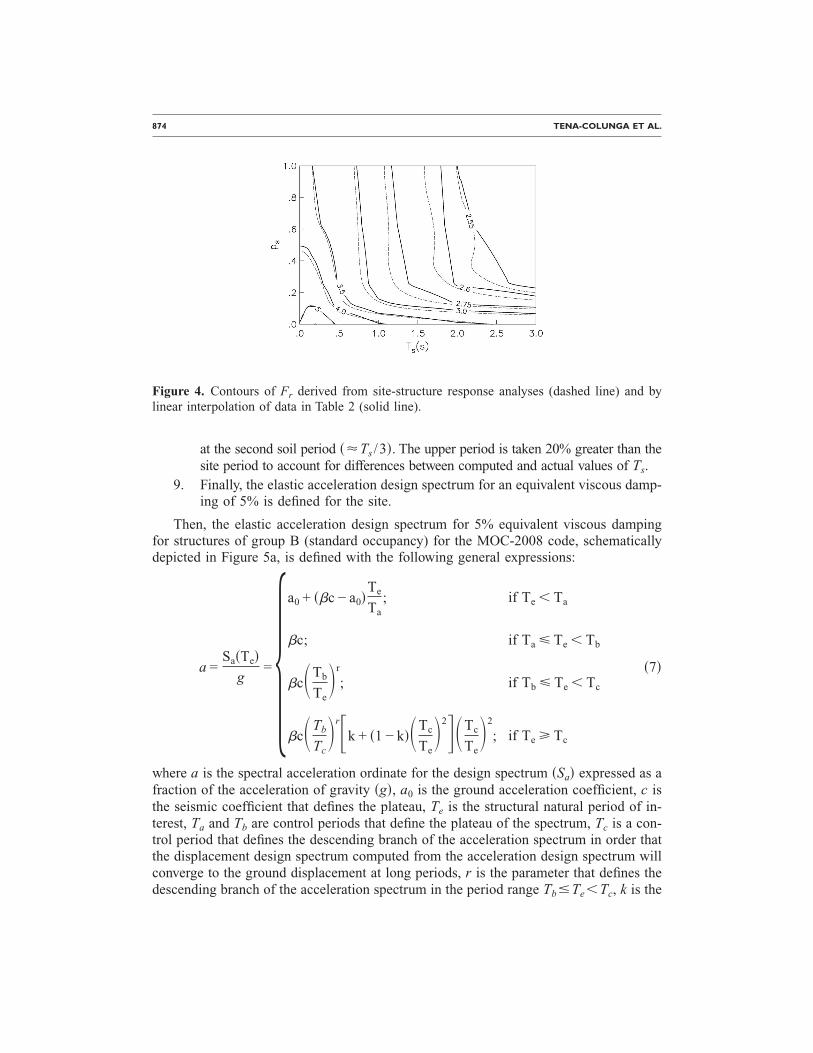
at the second soil period �Ts /3�. The upper period is taken 20% greater than thesite period to account for differences between computed and actual values of Ts.
9. Finally, the elastic acceleration design spectrum for an equivalent viscous damp-ing of 5% is defined for the site.
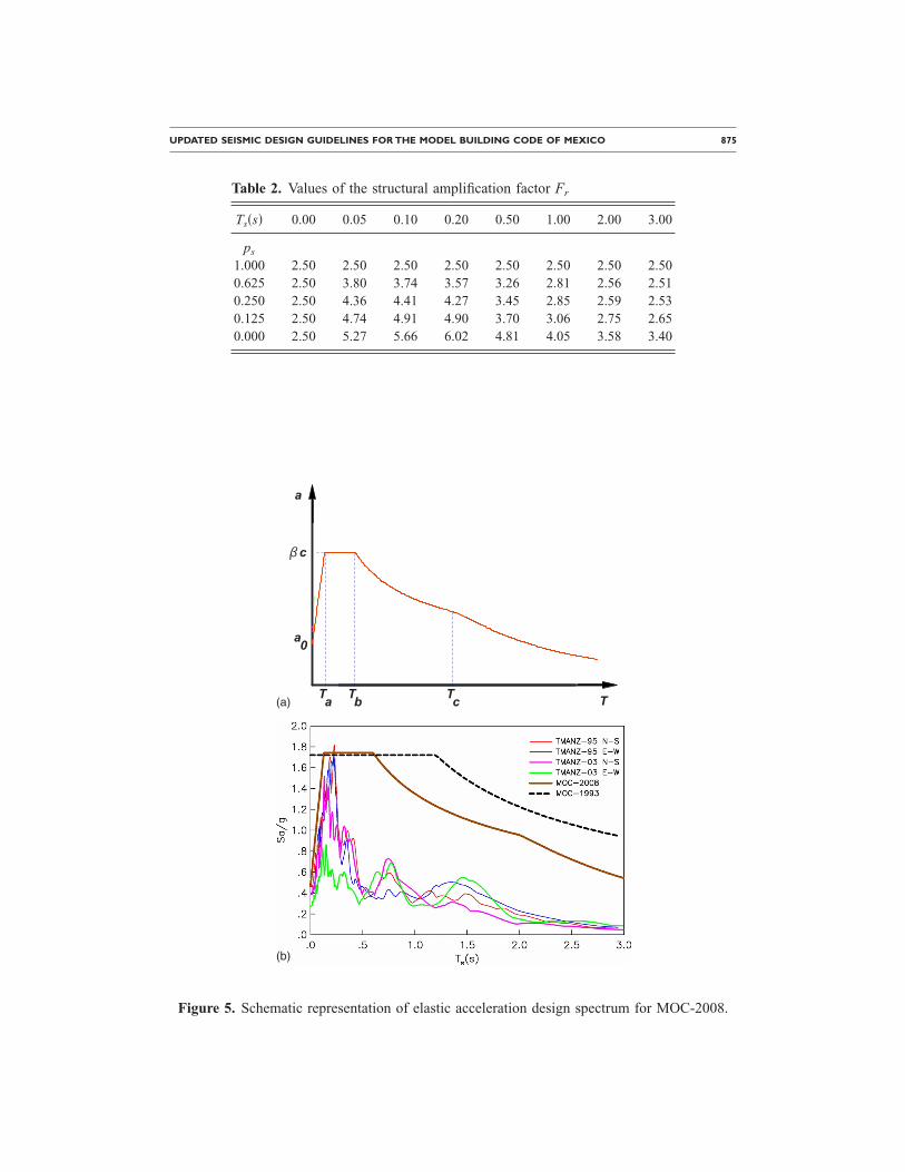
Then, the elastic acceleration design spectrum for 5% equivalent viscous dampingfor structures of group B (standard occupancy) for the MOC-2008 code, schematicallydepicted in Figure 5a, is defined with the following general expressions:
a =Sa�Te�
g=
a0 + ��c − a0�Te
Ta; if Te � Ta
�c; if Ta � Te � Tb
�c�Tb
Te�r
; if Tb � Te � Tc
�c�Tb
Tc�r�k + �1 − k��Tc
Te�2��Tc
Te�2
; if Te � Tc
�7�
where a is the spectral acceleration ordinate for the design spectrum �Sa� expressed as afraction of the acceleration of gravity �g�, a0 is the ground acceleration coefficient, c isthe seismic coefficient that defines the plateau, Te is the structural natural period of in-terest, Ta and Tb are control periods that define the plateau of the spectrum, Tc is a con-trol period that defines the descending branch of the acceleration spectrum in order thatthe displacement design spectrum computed from the acceleration design spectrum willconverge to the ground displacement at long periods, r is the parameter that defines thedescending branch of the acceleration spectrum in the period range Tb�Te�Tc, k is the
Figure 4. Contours of Fr derived from site-structure response analyses (dashed line) and bylinear interpolation of data in Table 2 (solid line).
UPDATED SEISMIC DESIGN GUIDELINES FOR THE MODEL BUILDING CODE OF MEXICO 875
Table 2. Values of the structural amplification factor Fr
Ts�s� 0.00 0.05 0.10 0.20 0.50 1.00 2.00 3.00
ps
1.000 2.50 2.50 2.50 2.50 2.50 2.50 2.50 2.500.625 2.50 3.80 3.74 3.57 3.26 2.81 2.56 2.510.250 2.50 4.36 4.41 4.27 3.45 2.85 2.59 2.530.125 2.50 4.74 4.91 4.90 3.70 3.06 2.75 2.650.000 2.50 5.27 5.66 6.02 4.81 4.05 3.58 3.40
T
a
Ta Tb Tc
a0
bbc
(a)
(b)
Figure 5. Schematic representation of elastic acceleration design spectrum for MOC-2008.
876 TENA-COLUNGA ET AL.
parameter that defines the descending branch of the acceleration spectrum when Te
�Tc and � is a damping factor. The control period Tc and the parameters r and k thatdefine the descending branch of the acceleration spectrum are defined as follows:
Tc = �2s if Tb � 2s
Tb if Tb � 2s� �8�
r = Ts; 0.5 � r � 1.0 �9�
k = �min�1.5,2 − Ts� if Ts � 1.65s
max�0.35,�/Fr� if Ts � 1.65s� �10�
where all terms have been already defined.
The damping factor � allow modifying the spectral ordinates for damping ratios dif-ferent from 5% to account primarily for soil-structure interaction effects and/or supple-mental damping and is defined by the following expressions:
� = �0.05
e�
where = 0.35 if Te � Tc
0.35�Te
Tc� if Te � Tc �11�
where e is the effective (target) damping of interest for the structural system. This pro-posal is based on a study conducted by Ruiz et al. (2008) for structural systems that maydevelop a reduced to moderate nonlinear response.
For important facilities (e.g., public schools and hospitals, structures in Group A),the spectral acceleration ordinates �a� given in Equation 7 should be multiplied by animportance factor I = 1.5. For essential facilities (for example, nuclear power plants,structures of group A+) an importance factor I ≥1.5 should be used depending on thehazard of the site (MOC-2008 2008).
The elastic design spectrum for the MCE obtained from MOC-2008 for ManzanilloPowerplant site (TMANZ) is compared in Figure 5b with the elastic design spectrumobtained from MOC-93 and with the elastic response spectra obtained for that site dur-ing the 9 October 1995 Manzanillo Earthquake �Mw=8.0� and the 21 January 2003Tecomán Earthquake �Mw=7.8�. One can observe that the design spectrum obtained withMOC-2008 is more realistic and less conservative for periods Te�0.7 s than the designspectrum previously defined by MOC-93.
ACCELERATION SPECTRUM FOR SERVICEABILITY LIMIT STATE
The acceleration design spectrum to check the serviceability of the damage state wasobtained using probabilistic cost-benefit analyses, where the fundamental period of thestructure is optimized by measuring damage through story drifts. Once the optimizedfundamental period �Tk� is obtained, the spectral acceleration required to reach the al-lowable story drift ��0� is assessed, as well as its corresponding return period.
It was found that, for practical purposes, the acceleration design spectrum to check
UPDATED SEISMIC DESIGN GUIDELINES FOR THE MODEL BUILDING CODE OF MEXICO 877
for the serviceability performance level can be obtained indirectly from the one definedfor the collapse prevention level divided by a factor of 5.5 and assuming linear behaviorfor the soil profile, therefore Fnl
a =FnlT =1.0. Then, a0, Ta and Tb are computed as:
a0 =Fsa0
r
5.5g�12�
Ta = 0.35Ts � 0.1s �13�
Tb = 1.2Ts � 0.6s �14�The remaining parameters used to define the acceleration design spectrum remain
unchanged. The described spectrum should be used to review damage prevention (linearbehavior) for the structural system for both essential and standard occupancy buildingstructures. The importance factor is neglected for important and essential facilities (noamplification for this concept).
DISPLACEMENT DESIGN SPECTRUM
Displacement design spectrum Sd�Te� is obtained indirectly from acceleration designspectrum based upon standard relation from structural dynamics:
Sd�Te� =Te
2
4�2Sa�Te� �15�
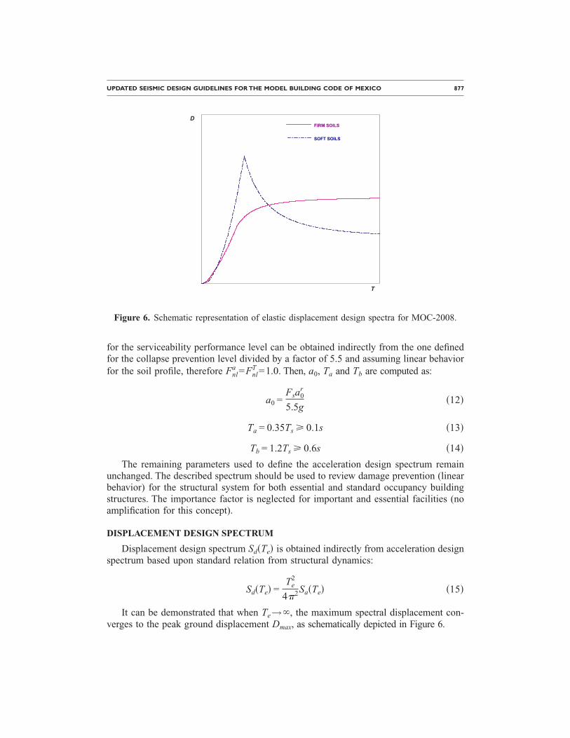
It can be demonstrated that when Te→ , the maximum spectral displacement con-verges to the peak ground displacement Dmax, as schematically depicted in Figure 6.
T
DFIRM SOILS
SOFT SOILS
Figure 6. Schematic representation of elastic displacement design spectra for MOC-2008.
878 TENA-COLUNGA ET AL.
When k�1, the maximum spectral displacement occurs when Te=Tc and is givenby:
Sdmax= �
cTc2
4�2�Tb
Tc�1/2
g �16�
If k�1 the maximum spectral displacement occurs when Te→ and converges tothe peak ground displacement Dmax, that it is independent of the damping coefficient �, andis given by:
Dmax = kcTc
2
4�2�Tb
Tc�1/2
g �17�
Therefore, from Equations 16 and 17 it is clear that the parameter k has a physicalmeaning as it is the ratio between the peak ground displacement and the maximum spec-tral displacement modified by the damping coefficient �:
k =Dmax
Sdmax/�
�18�
The shape of the displacement design spectrum depends on several parameters thatdefine the absence or presence of site effects, but three of them are particularly impor-tant: the k parameter, the site factor Fs and the fundamental site period Ts. For relativelyfirm to firm soils or rocks (Ts�0.8 s, Fs�1.5), design displacement spectrum convergesto the peak ground displacement in an asymptotic manner (“firm soils,” Figure 6), whereasfor relatively soft to very soft soils (Ts�1.3 s, Fs�1.5), design displacement spectrumreaches a peak value when Te=Tc and decay to converge to the ground displacement (“softsoils,” Figure 6).
REDUCTION OF ELASTIC RESPONSE PARAMETERS FOR DESIGN
For the sake of clarity in the design process, there is an important conceptual adjust-ment in the reduction of elastic response parameters for design in MOC-2008 with re-spect to that in MOC-93. In the earlier code, the elastic design spectra were reduced bydividing the spectral ordinates by a somewhat obscure reductive seismic force factor Q�that accounted for everything (ductility, redundancy, overstrength, etc.).
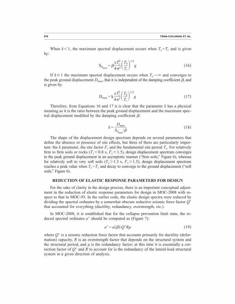
In MOC-2008, it is established that for the collapse prevention limit state, the re-duced spectral ordinates a� should be computed as (Figure 7):
a� = a���/Q�R� �19�
where Q� is a seismic reduction force factor that accounts primarily for ductility (defor-mation) capacity, R is an overstrength factor that depends on the structural system andthe structural period, and � is the redundancy factor; at this time it is essentially a cor-rection factor of Q� and R to account for is the redundancy of the lateral-load structuralsystem in a given direction of analysis.
UPDATED SEISMIC DESIGN GUIDELINES FOR THE MODEL BUILDING CODE OF MEXICO 879
For structural systems with stiffness and/or strength degrading characteristics undercyclic loading located in soft soils, the reduced spectral ordinates a� should be computedas
a� = a���Acd/Q�R� �20�
where Acd is a modification factor to account for stiffness and/or strength degradation insoft soils.
All these parameters are explained in greater detail below.
SEISMIC RESPONSE MODIFICATION FACTOR Q
The definition, requirements, and proposed values for the seismic response modifi-cation factor Q remain practically unchanged in MOC-2008. The values for Q estab-lished by all modern Mexican codes are 1, 1.5, 2, 3, and 4, and they depend on the se-lected structural system (Tena-Colunga 1999). For example, in order to use Q=3 or Q=4 for dual systems, the designer has to demonstrate that the dual system satisfies spe-cific requirements related to the strength and stiffness balances of frames with respect toshear walls and/or braced frames. The Q factors of Mexican codes account primarily forthe deformation capacity of the structural system and its relation with its displacementductility, redundancy and overstrength.
DUCTILITY REDUCTION FACTOR Q�
In the MOC-2008 code, the seismic reduction force factor Q� stands now only forthe approximate ductility deformation capacity of the selected structural system, givenin terms of the seismic response modification factor Q. For any given structural system,Q� should be computed as follows:
a
a0
bbc
TTa Tb Tc
Elastic
Inelastic
Q´Rp
a0Rp
Figure 7. Schematic representation of inelastic acceleration design spectrum for MOC-2008.
880 TENA-COLUNGA ET AL.
Q� =1 + �Q − 1���
k�Tc
Tb�rTe
Tc; if Te � Tb
1 + �Q − 1���
k�Tc
Te�rTe
Tc; if Tb � Te � Tc
1 + �Q − 1���p/k; if Te � Tc
�21�
where p is a factor to define the descendent curve of the inelastic response spectrumgiven by:
p = k + �1 − k��Tc
Te�2
�22�
and all remaining terms have already been defined.
Therefore, it can be observed from Equation 21 that the proposed Q� factor is notconstant and depends on the structural period Te and the site period Ts (in terms of pa-rameters Ta, Tc and k). In fact, the proposal for Q� mostly coincides with the proposalavailable in Appendix A of the seismic provisions for current Mexico’s Federal DistrictCode (NTCS-2004 2004). This proposal is based on the study of SDOF systems withelastoplastic hysteretic behavior (for example, Krawinkler and Rahnama 1992, Miranda1993, Miranda and Bertero 1994, Ordaz and Pérez-Rocha 1998), where Q� is the ratiobetween the minimum strength required to limit a structural system to an elastic re-sponse C�Te ,1� and the strength required for a structural system to limit its ductilitycapacity to a given Q value C�Te ,Q�, this is:
Q��Te,Q� =C�Te,1�C�Te,Q�
�23�
Ordaz and Pérez-Rocha (1998) showed that, in general terms, Q� depends on the ra-tio between the spectral displacement Sd�Te� and the peak ground displacement Dmax as:
Q��Te,Q� = 1 + �Q − 1��Sd�Te�Dmax
��
�24�
where � �0.5.
The proposed Equations 21 and 22 are a simplified version of Equation 24. A de-tailed explanation on how these expressions were derived are presented elsewhere(MOC-2008 2008) and briefly summarized here.
For Te=0, Q��Te ,Q�=1 independently of the proposed Q value. For the sake of sim-plicity, a linear variation is taken between Q�=1 for Te=0 and Q�=Qmax� for Te=Ta.Then, Qmax� is obtained when Sd�Te� is maximum that occurs when Te=Tc. Therefore, it canbe demonstrated from Equations 18 and 24 that if � = 0.5, then
Qmax� = 1 + �Q − 1����25�
k
UPDATED SEISMIC DESIGN GUIDELINES FOR THE MODEL BUILDING CODE OF MEXICO 881
The equation for the descending branch �Te�Tc� is obtained taking into consider-ation that, from basic structural dynamic principles, for long periods �Te→ � the asso-ciated elastic displacement spectrum converges to the peak ground displacement Dmax
and also Q� should converge to Q.
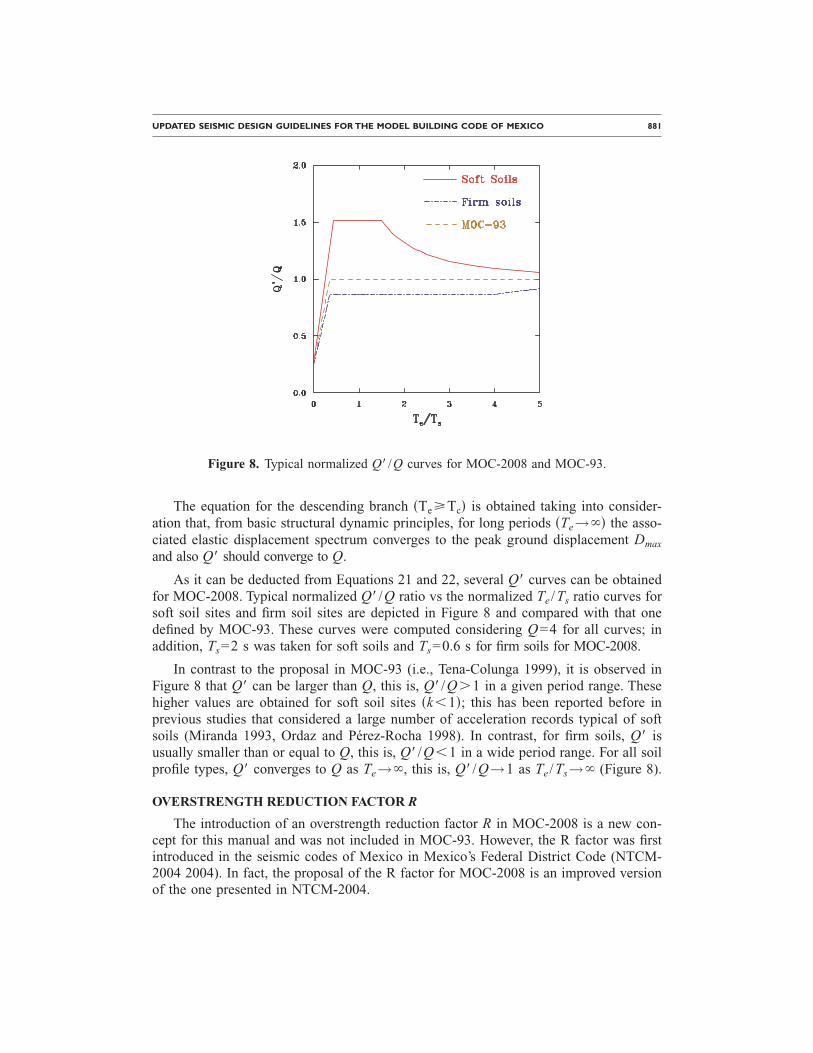
As it can be deducted from Equations 21 and 22, several Q� curves can be obtainedfor MOC-2008. Typical normalized Q� /Q ratio vs the normalized Te /Ts ratio curves forsoft soil sites and firm soil sites are depicted in Figure 8 and compared with that onedefined by MOC-93. These curves were computed considering Q=4 for all curves; inaddition, Ts=2 s was taken for soft soils and Ts=0.6 s for firm soils for MOC-2008.
In contrast to the proposal in MOC-93 (i.e., Tena-Colunga 1999), it is observed inFigure 8 that Q� can be larger than Q, this is, Q� /Q�1 in a given period range. Thesehigher values are obtained for soft soil sites �k�1�; this has been reported before inprevious studies that considered a large number of acceleration records typical of softsoils (Miranda 1993, Ordaz and Pérez-Rocha 1998). In contrast, for firm soils, Q� isusually smaller than or equal to Q, this is, Q� /Q�1 in a wide period range. For all soilprofile types, Q� converges to Q as Te→ , this is, Q� /Q→1 as Te /Ts→ (Figure 8).
OVERSTRENGTH REDUCTION FACTOR R
The introduction of an overstrength reduction factor R in MOC-2008 is a new con-cept for this manual and was not included in MOC-93. However, the R factor was firstintroduced in the seismic codes of Mexico in Mexico’s Federal District Code (NTCM-2004 2004). In fact, the proposal of the R factor for MOC-2008 is an improved versionof the one presented in NTCM-2004.
Figure 8. Typical normalized Q� /Q curves for MOC-2008 and MOC-93.
882 TENA-COLUNGA ET AL.
The proposal for R in MOC-2008 is given by the following equations:
R = �R0 + 0.5�1 − �Te/Ta�; if Te � Ta
R0; if Te � Ta� �26�
where R0 is an overstrength index value that depends on the structural system. For ex-ample, R0=2 for ordinary and intermediate moment-resisting frames, ordinary moment-resisting braced frames and confined masonry wall structures made with hollow units(ungrouted or partially grouted); R0=2.5 for special moment-resisting frames, intermediatemoment-resisting braced frames, and confined masonry wall structures made with solidunits; R0=3.0 is for dual systems built with special moment-resisting frame connections.
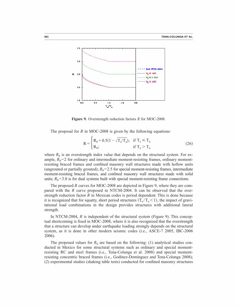
The proposed R curves for MOC-2008 are depicted in Figure 9, where they are com-pared with the R curve proposed in NTCM-2004. It can be observed that the over-strength reduction factor R in Mexican codes is period dependent. This is done becauseit is recognized that for squatty, short period structures �Te/Ta�1�, the impact of gravi-tational load combinations in the design provides structures with additional lateralstrength.
In NTCM-2004, R is independent of the structural system (Figure 9). This concep-tual shortcoming is fixed in MOC-2008, where it is also recognized that the overstrengththat a structure can develop under earthquake loading strongly depends on the structuralsystem, as it is done in other modern seismic codes (i.e., ASCE-7 2005, IBC-20062006).
The proposed values for R0 are based on the following: (1) analytical studies con-ducted in Mexico for some structural systems such as ordinary and special moment-resisting RC and steel frames (i.e., Tena-Colunga et al. 2008) and special moment-resisting concentric braced frames (i.e., Godínez-Domínguez and Tena-Colunga 2008);(2) experimental studies (shaking table tests) conducted for confined masonry structures
Figure 9. Overstrength reduction factors R for MOC-2008.
UPDATED SEISMIC DESIGN GUIDELINES FOR THE MODEL BUILDING CODE OF MEXICO 883
(i.e., Barragán et al. 2008); and (3) proposed values of NTCM-2004 and U.S. codes,such as ASCE 7-05 and IBC-2006. Of course, the current proposal for MOC-2008 hasroom for improvement as more reliable data regarding the assessment of overstrength fordifferent structural systems will be available in the future.
REDUNDANCY FACTOR �
The introduction of a redundancy factor � in MOC-2008 is a new concept for Mexi-can seismic design codes, not only for MOC-2008. The purpose of this “new” factor isto recognize directly that structural systems are able to develop more strength and in-crease their deformation capacity as they become more redundant. This fact is well-known by the structural engineering community worldwide. However, it seems someseismic codes have come up short before, by not recognizing that a more redundantstructural system under lateral loading should be allowed to be designed with higher re-ductions and that weakly-redundant systems should be penalized and be designed withsmaller reductions.
In MOC-2008, � is a factor that basically corrects the previous assessment of theoverstrength factor R, as most of the available studies where R has been computed havebeen mostly done in 2-D models with different degrees of redundancy. In addition, thisfactor takes into account unfavorable performances of weakly-redundant structures instrong earthquakes occurred worldwide in the last 30 years.
The proposed values for � in MOC-2008 are the following:
• � = 0.8 for structures with at least two earthquake-resistant parallel frames orlines of defense in the direction of analysis, if such frames are one-bay frames (orequivalent structural systems).
• � = 1 for structures with at least two earthquake-resistant parallel frames or linesof defense in the direction of analysis, if such frames have at least two bays (orequivalent structural systems).
• � = 1.25 for structures with at least three earthquake-resistant parallel frames orlines of defense in the direction of analysis, if such frames have at least threebays (or equivalent structural systems).
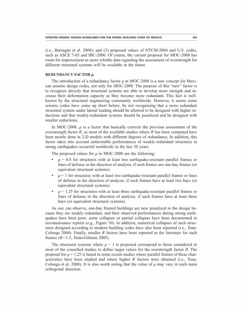
As one can observe, one-bay framed buildings are now penalized in the design be-cause they are weakly redundant, and their observed performances during strong earth-quakes have been poor; some collapses or partial collapses have been documented inreconnaissance reports (e.g., Figure 10). In addition, numerical collapses of such struc-tures designed according to modern building codes have also been reported (i.e., Tena-Colunga 2004). Finally, smaller R factors have been reported in the literature for suchframes (R=1.5, Terán-Gilmore 2005).
The structural systems where � = 1 is proposed correspond to those considered inmost of the consulted studies to define target values for the overstrength factor R. Theproposal for � = 1.25 is based in some recent studies where parallel frames of these char-acteristics have been studied and where higher R factors were obtained (i.e., Tena-Colunga et al. 2008). It is also worth noting that the value of � may vary in each main
orthogonal direction.
884 TENA-COLUNGA ET AL.
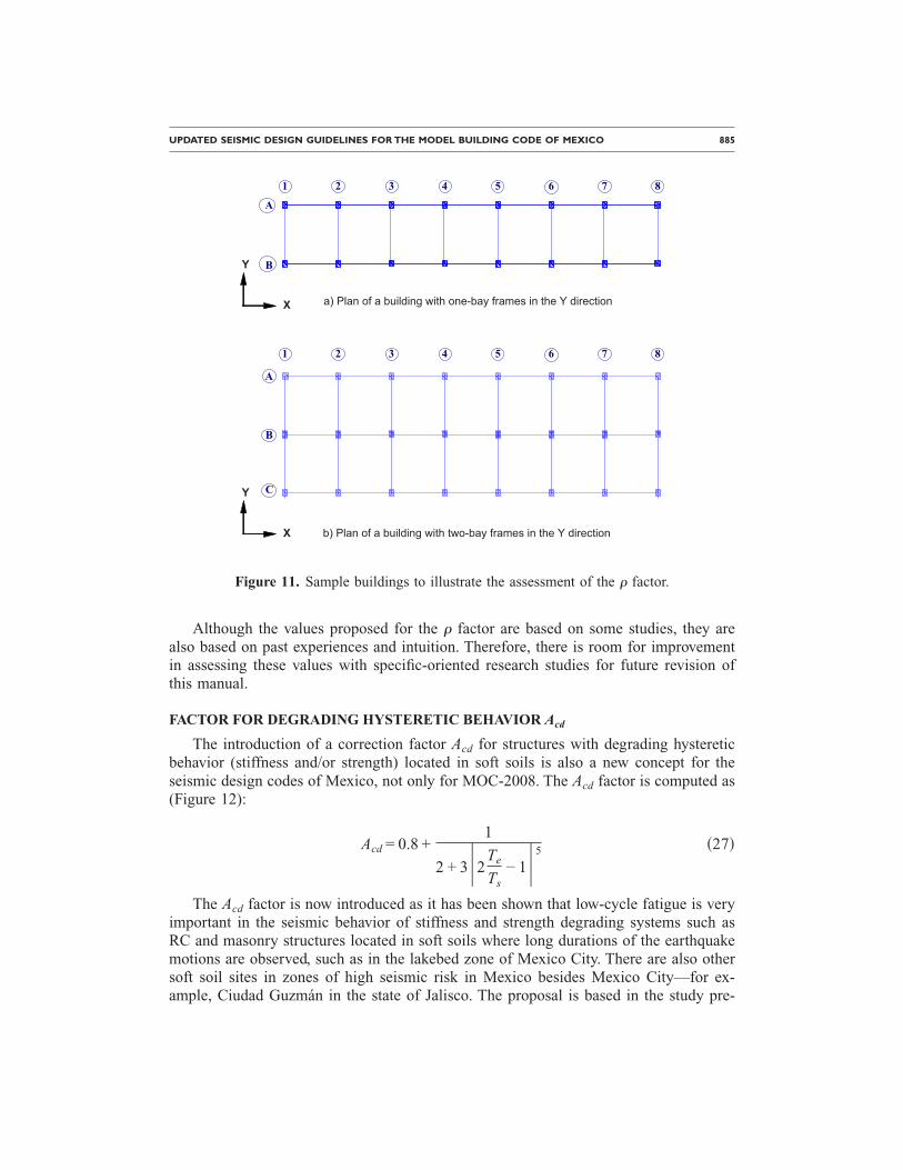
The assessment of the � factor for a given structure is straight-forward and it is il-lustrated with the buildings which plans are depicted in Figure 11. For the building plandepicted in Figure 11a, � = 0.8 should be taken in the Y direction as it has eight parallelone-bay frames, whereas in the X direction, � = 1 because it has two parallel seven-bayframes. In contrast, for the building plan depicted in Figure 11b, � = 1 should be takenin the Y direction as it has eight parallel two-bay frames, whereas in the X direction, �= 1.25 because it has three parallel seven-bay frames.
This simple example illustrates the philosophy behind the new � factor. A-priori,most engineers would agree that the building plan depicted in Figure 11b is more re-dundant than the building plan depicted in Figure 11a. Former Mexican codes did notrecognize directly this fact for their seismic design, now MOC-2008 does. It is hopedthat this approach would help structural engineers to promote the use of more redundantstructural systems in zones of high earthquake hazard and to limit or avoid the use ofweakly-redundant structures (i.e., Figure 10 and 11a).
Figure 10. One-bay framed building severely damaged during 1995 Kobe earthquake(http://www.eqe.com/publications/kobe/building.htm).
UPDATED SEISMIC DESIGN GUIDELINES FOR THE MODEL BUILDING CODE OF MEXICO 885
Although the values proposed for the � factor are based on some studies, they arealso based on past experiences and intuition. Therefore, there is room for improvementin assessing these values with specific-oriented research studies for future revision ofthis manual.
FACTOR FOR DEGRADING HYSTERETIC BEHAVIOR Acd
The introduction of a correction factor Acd for structures with degrading hystereticbehavior (stiffness and/or strength) located in soft soils is also a new concept for theseismic design codes of Mexico, not only for MOC-2008. The Acd factor is computed as(Figure 12):
Acd = 0.8 +1
2 + 3�2Te
Ts− 1�5 �27�
The Acd factor is now introduced as it has been shown that low-cycle fatigue is veryimportant in the seismic behavior of stiffness and strength degrading systems such asRC and masonry structures located in soft soils where long durations of the earthquakemotions are observed, such as in the lakebed zone of Mexico City. There are also othersoft soil sites in zones of high seismic risk in Mexico besides Mexico City—for ex-ample, Ciudad Guzmán in the state of Jalisco. The proposal is based in the study pre-
4 5 7 82 31 6
B
A
4 5 7 8
C
2 31 6
B
A
a) Plan of a building with one-bay frames in the Y directionX
Y
X
Y
b) Plan of a building with two-bay frames in the Y direction
Figure 11. Sample buildings to illustrate the assessment of the � factor.
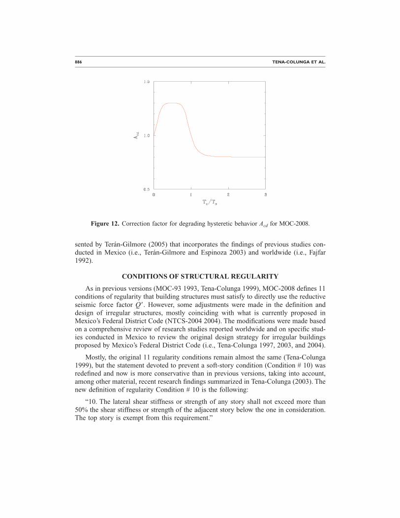
886 TENA-COLUNGA ET AL.
sented by Terán-Gilmore (2005) that incorporates the findings of previous studies con-ducted in Mexico (i.e., Terán-Gilmore and Espinoza 2003) and worldwide (i.e., Fajfar1992).
CONDITIONS OF STRUCTURAL REGULARITY
As in previous versions (MOC-93 1993, Tena-Colunga 1999), MOC-2008 defines 11conditions of regularity that building structures must satisfy to directly use the reductiveseismic force factor Q�. However, some adjustments were made in the definition anddesign of irregular structures, mostly coinciding with what is currently proposed inMexico’s Federal District Code (NTCS-2004 2004). The modifications were made basedon a comprehensive review of research studies reported worldwide and on specific stud-ies conducted in Mexico to review the original design strategy for irregular buildingsproposed by Mexico’s Federal District Code (i.e., Tena-Colunga 1997, 2003, and 2004).
Mostly, the original 11 regularity conditions remain almost the same (Tena-Colunga1999), but the statement devoted to prevent a soft-story condition (Condition # 10) wasredefined and now is more conservative than in previous versions, taking into account,among other material, recent research findings summarized in Tena-Colunga (2003). Thenew definition of regularity Condition # 10 is the following:
“10. The lateral shear stiffness or strength of any story shall not exceed more than50% the shear stiffness or strength of the adjacent story below the one in consideration.The top story is exempt from this requirement.”
Figure 12. Correction factor for degrading hysteretic behavior Acd for MOC-2008.
UPDATED SEISMIC DESIGN GUIDELINES FOR THE MODEL BUILDING CODE OF MEXICO 887
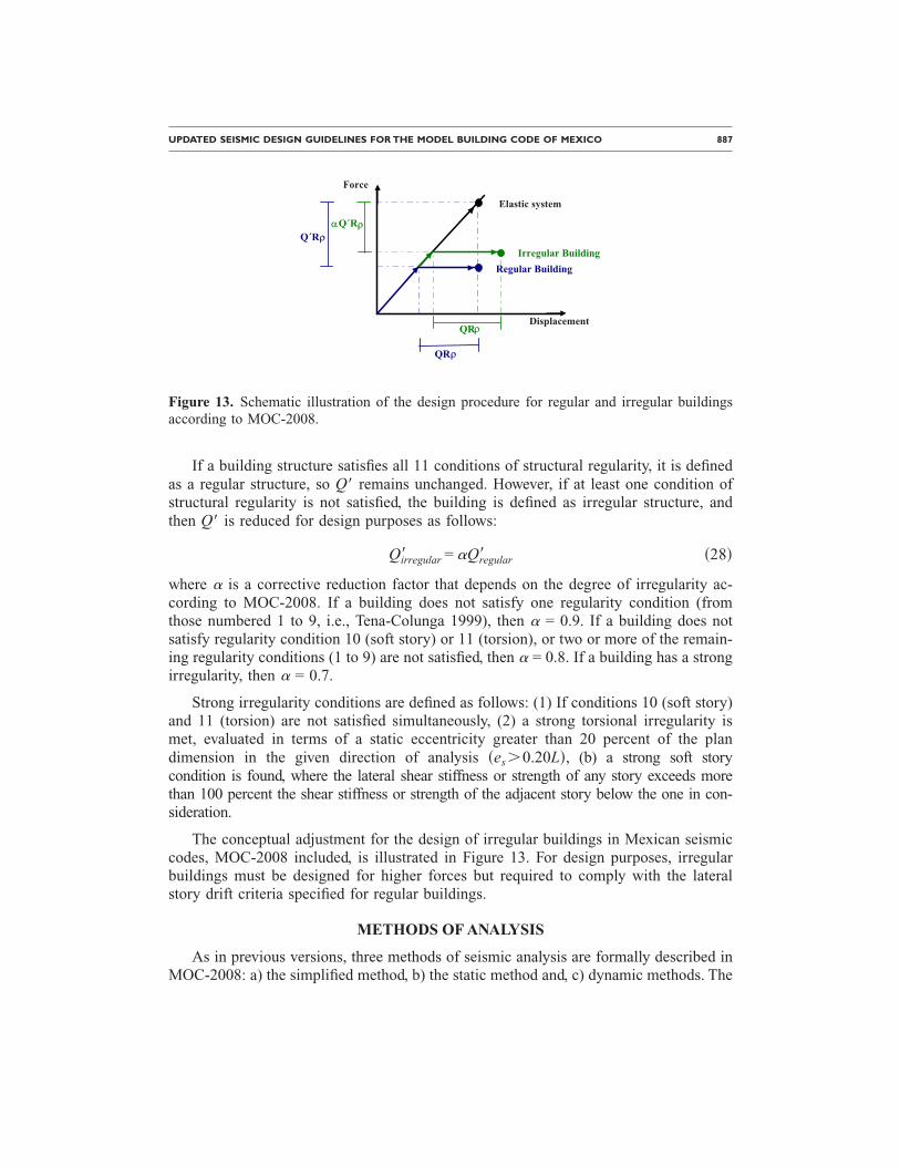
If a building structure satisfies all 11 conditions of structural regularity, it is definedas a regular structure, so Q� remains unchanged. However, if at least one condition ofstructural regularity is not satisfied, the building is defined as irregular structure, andthen Q� is reduced for design purposes as follows:
Qirregular� = �Qregular� �28�
where � is a corrective reduction factor that depends on the degree of irregularity ac-cording to MOC-2008. If a building does not satisfy one regularity condition (fromthose numbered 1 to 9, i.e., Tena-Colunga 1999), then � = 0.9. If a building does notsatisfy regularity condition 10 (soft story) or 11 (torsion), or two or more of the remain-ing regularity conditions (1 to 9) are not satisfied, then � = 0.8. If a building has a strongirregularity, then � = 0.7.
Strong irregularity conditions are defined as follows: (1) If conditions 10 (soft story)and 11 (torsion) are not satisfied simultaneously, (2) a strong torsional irregularity ismet, evaluated in terms of a static eccentricity greater than 20 percent of the plandimension in the given direction of analysis �es�0.20L�, (b) a strong soft storycondition is found, where the lateral shear stiffness or strength of any story exceeds morethan 100 percent the shear stiffness or strength of the adjacent story below the one in con-sideration.
The conceptual adjustment for the design of irregular buildings in Mexican seismiccodes, MOC-2008 included, is illustrated in Figure 13. For design purposes, irregularbuildings must be designed for higher forces but required to comply with the lateralstory drift criteria specified for regular buildings.
METHODS OF ANALYSIS
As in previous versions, three methods of seismic analysis are formally described inMOC-2008: a) the simplified method, b) the static method and, c) dynamic methods. The
Displacement
Force
Irregular BuildingRegular Building
Elastic system
Q´R� �Q´R�
QR�
QR�
Figure 13. Schematic illustration of the design procedure for regular and irregular buildingsaccording to MOC-2008.
888 TENA-COLUNGA ET AL.
general description of the methods is available in English language elsewhere (Tena-Colunga 1999). In the following sections the more important updates for each methodwill be briefly described.
SIMPLIFIED METHOD
The simplified method is allowed for low-rise (up to five stories or less than 13 m inheight), bearing-wall, shear-wall structures with no mass or stiffness eccentricities, dia-phragm flexibility, and/or slenderness effects, where seismic forces are determined usingreduced seismic coefficients specified according to the soil profile, the height of thestructure and the type of bearing wall used. Seismic forces are distributed among struc-tural elements according to their shear stiffnesses. A more detailed description of thesimplified method and its theoretical background is presented elsewhere (Tena-Colungaand Cano-Licona 2007).
The simplified method has been extensively reviewed recently and based upon theseparametric studies (i.e., Tena-Colunga and Cano-Licona 2007, Tena-Colunga and López-Blancas 2006), important adjustments were made. In particular, new, improved effectiveshear area factors FAE are proposed for two different limit states for the structure.
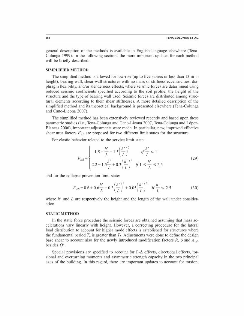
For elastic behavior related to the service limit state:
FAE = 1.5 +h�
L− 1.5�h�
L�2
ifh�
L� 1
2.2 − 1.5h�
L+ 0.3�h�
L�2
if 1 �h�
L� 2.5 �29�
and for the collapse prevention limit state:
FAE = 0.6 + 0.6h�
L− 0.3�h�
L�2
+ 0.05�h�
L�3
ifh�
L� 2.5 �30�
where h� and L are respectively the height and the length of the wall under consider-ation.
STATIC METHOD
In the static force procedure the seismic forces are obtained assuming that mass ac-celerations vary linearly with height. However, a correcting procedure for the lateralload distribution to account for higher mode effects is established for structures wherethe fundamental period Te is greater than Tb. Adjustments were done to define the designbase shear to account also for the newly introduced modification factors R, � and Acd,besides Q�.
Special provisions are specified to account for P-∆ effects, directional effects, tor-sional and overturning moments and asymmetric strength capacity in the two principalaxes of the building. In this regard, there are important updates to account for torsion,
UPDATED SEISMIC DESIGN GUIDELINES FOR THE MODEL BUILDING CODE OF MEXICO 889
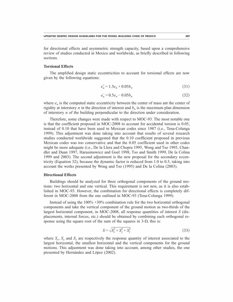
for directional effects and asymmetric strength capacity, based upon a comprehensivereview of studies conducted in Mexico and worldwide, as briefly described in followingsections.
Torsional Effects
The amplified design static eccentricities to account for torsional effects are nowgiven by the following equations:
en+ = 1.5en + 0.05bn �31�
en− = 0.5en − 0.05bn �32�
where en is the computed static eccentricity between the center of mass ant the center ofrigidity at interstory n in the direction of interest and bn is the maximum plan dimensionof interstory n of the building perpendicular to the direction under consideration.
Therefore, some changes were made with respect to MOC-93. The most notable oneis that the coefficient proposed in MOC-2008 to account for accidental torsion is 0.05,instead of 0.10 that have been used in Mexican codes since 1987 (i.e., Tena-Colunga1999). This adjustment was done taking into account that results of several researchstudies conducted worldwide suggested that the 0.10 coefficient proposed in previousMexican codes was too conservative and that the 0.05 coefficient used in other codesmight be more adequate (i.e., De la Llera and Chopra 1995, Wong and Tso 1995, Chan-dler and Duan 1997, Harasimowicz and Goel 1998, Tso and Smith 1999, De la Colina1999 and 2003). The second adjustment is the new proposal for the secondary eccen-tricity (Equation 32), because the dynamic factor is reduced from 1.0 to 0.5, taking intoaccount the works presented by Wong and Tso (1995) and De la Colina (2003).
Directional Effects
Buildings should be analyzed for three orthogonal components of the ground mo-tions: two horizontal and one vertical. This requirement is not new, as it is also estab-lished in MOC-93. However, the combination for directional effects is completely dif-ferent in MOC-2008 from the one outlined in MOC-93 (Tena-Colunga 1999).
Instead of using the 100% +30% combination rule for the two horizontal orthogonalcomponents and take the vertical component of the ground motion as two-thirds of thelargest horizontal component, in MOC-2008, all response quantities of interest S (dis-placements, internal forces, etc.) should be obtained by combining each orthogonal re-sponse using the square root of the sum of the squares in 3-D, this is:
S = �Sx2 + Sy
2 + Sz2 �33�
where Sx, Sy and Sz are respectively the response quantity of interest associated to thelargest horizontal, the smallest horizontal and the vertical components for the groundmotions. This adjustment was done taking into account, among other studies, the onepresented by Hernández and López (2002).
890 TENA-COLUNGA ET AL.
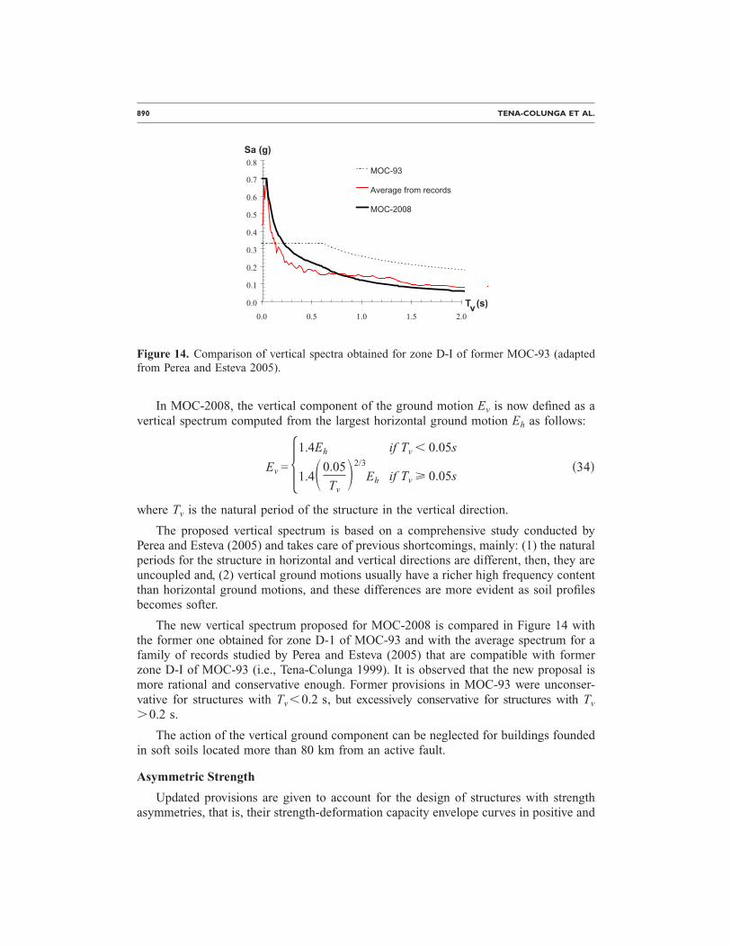
In MOC-2008, the vertical component of the ground motion Ev is now defined as avertical spectrum computed from the largest horizontal ground motion Eh as follows:
Ev = 1.4Eh if Tv � 0.05s
1.4�0.05
Tv�2/3
Eh if Tv � 0.05s �34�
where Tv is the natural period of the structure in the vertical direction.
The proposed vertical spectrum is based on a comprehensive study conducted byPerea and Esteva (2005) and takes care of previous shortcomings, mainly: (1) the naturalperiods for the structure in horizontal and vertical directions are different, then, they areuncoupled and, (2) vertical ground motions usually have a richer high frequency contentthan horizontal ground motions, and these differences are more evident as soil profilesbecomes softer.
The new vertical spectrum proposed for MOC-2008 is compared in Figure 14 withthe former one obtained for zone D-1 of MOC-93 and with the average spectrum for afamily of records studied by Perea and Esteva (2005) that are compatible with formerzone D-I of MOC-93 (i.e., Tena-Colunga 1999). It is observed that the new proposal ismore rational and conservative enough. Former provisions in MOC-93 were unconser-vative for structures with Tv�0.2 s, but excessively conservative for structures with Tv
�0.2 s.
The action of the vertical ground component can be neglected for buildings foundedin soft soils located more than 80 km from an active fault.
Asymmetric Strength
Updated provisions are given to account for the design of structures with strengthasymmetries, that is, their strength-deformation capacity envelope curves in positive and
0.0
0.1
0.2
0.3
0.4
0.5
0.6
0.7
0.8
0.0 0.5 1.0 1.5 2.0
MOC-93
Average from records
MOC-2008
Sa (g)
T (s)v
Figure 14. Comparison of vertical spectra obtained for zone D-I of former MOC-93 (adaptedfrom Perea and Esteva 2005).
UPDATED SEISMIC DESIGN GUIDELINES FOR THE MODEL BUILDING CODE OF MEXICO 891
negative directions are different. The new proposal is based in the study presented byTerán-Gilmore and Arroyo (2005) and provides improved equations for firm soils andsoft soil sites.
DYNAMIC METHOD
According to MOC-2008, the following options can be used for dynamic analysis:(1) response-spectrum analysis and (2) time-history analysis. The general recommenda-tions to use both methods remain practically unchanged from previous MOC-93 version(i.e., Tena-Colunga 1999). However, there are some fine adjustments for both proce-dures.
In the response spectrum analysis, accidental torsional effects are accounted in thedesign by translating ±0.05bn as the centers of mass at each level for each horizontal di-rection of analysis. This recommendation would require the use of four additional models toassess the impact of the modal coupling due to accidental torsion. As an option, one can usea single model if the line of action of the lateral forces obtained from the response spectrumanalysis is translated ±0.05bn at each level, this is, a static torque is applied as an approxi-mation of the modal coupling due to accidental torsion. In addition, SRSS or CQC combi-nation procedures are specified; however, it is clearly stated that SRSS method can only beused if the natural periods for the building in each given direction differ in 10% or more.
For time-history analysis, it is clearly specified that the acceleration ground motionsto include in the analyses must be fully compatible with the seismic hazard for the siteof interest, as outlined in an specialized section of the manual. At least four representa-tive trios of representative ground motions should be included in the analyses. The non-linear characteristics of the structural system and their associated uncertainties shall betaken into account.
For either option of dynamic analysis, the corresponding design base shear shall notbe less than 80% of the base shear determined by the static force procedure.
REVIEW OF LIMIT STATES
In MOC-2008, four limit states have to be reviewed for seismic loading: (1) storydrift limits for the service earthquake, (2) story drift limits for collapse prevention underthe maximum credible earthquake (MCE), (3) glass gaps under the MCE and, (4) build-ing separations under the MCE.
The recommendations for glass gaps and buildings separations (i.e., Tena-Colunga1999) remain unchanged from the previous code.
The review of drift limits for the service earthquake is new in MOC-2008, but not inMexican codes, as this review is specified in NTCS-2004. In fact, the proposal in MOC-2008 is based upon what it is defined in NTCS-2004. For the service earthquake, build-ings should remain elastic, so the proposed story drift limits are �ser�0.002 if non-structural elements are not properly separated from the structural system and �ser�0.004 ifnon-structural elements are properly separated from the structural system.
For the collapse prevention state, story drifts are obtained from the displacements
892 TENA-COLUNGA ET AL.
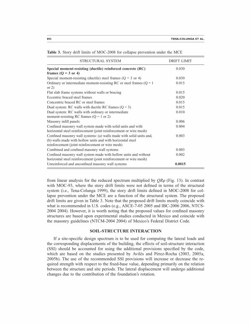
from linear analysis for the reduced spectrum multiplied by QR� (Fig. 13). In contrastwith MOC-93, where the story drift limits were not defined in terms of the structuralsystem (i.e., Tena-Colunga 1999), the story drift limits defined in MOC-2008 for col-lapse prevention under the MCE are a function of the structural system. The proposeddrift limits are given in Table 3. Note that the proposed drift limits mostly coincide withwhat is recommended in U.S. codes (e.g., ASCE-7-05 2005 and IBC-2006 2006, NTCS-2004 2004). However, it is worth noting that the proposed values for confined masonrystructures are based upon experimental studies conducted in Mexico and coincide withthe masonry guidelines (NTCM-2004 2004) of Mexico’s Federal District Code.
SOIL-STRUCTURE INTERACTION
If a site-specific design spectrum is to be used for computing the lateral loads andthe corresponding displacements of the building, the effects of soil-structure interaction(SSI) should be accounted for using the additional provisions specified by the code,which are based on the studies presented by Avilés and Pérez-Rocha (2003, 2005a,2005b). The use of the recommended SSI provisions will increase or decrease the re-quired strength with respect to the fixed-base value, depending primarily on the relationbetween the structure and site periods. The lateral displacement will undergo additionalchanges due to the contribution of the foundation’s rotation.
Table 3. Story drift limits of MOC-2008 for collapse prevention under the MCE
STRUCTURAL SYSTEM DRIFT LIMIT
Special moment-resisting (ductile) reinforced concrete (RC)frames (Q = 3 or 4)
0.030
Special moment-resisting (ductile) steel frames (Q = 3 or 4) 0.030Ordinary or intermediate moment-resisting RC or steel frames (Q = 1or 2)
0.015
Flat slab frame systems without walls or bracing 0.015Eccentric braced steel frames 0.020Concentric braced RC or steel frames 0.015Dual system: RC walls with ductile RC frames (Q = 3) 0.015Dual system: RC walls with ordinary or intermediatemoment-resisting RC frames (Q = 1 or 2)
0.010
Masonry infill panels 0.006Confined masonry wall system made with solid units and withhorizontal steel reinforcement (joint reinforcement or wire mesh)
0.004
Confined masonry wall systems: (a) walls made with solid units and,(b) walls made with hollow units and with horizontal steelreinforcement (joint reinforcement or wire mesh)
0.003
Combined and confined masonry wall systems 0.003Confined masonry wall system made with hollow units and withouthorizontal steel reinforcement (joint reinforcement or wire mesh)
0.002
Unreinforced and unconfined masonry wall systems 0.0015
UPDATED SEISMIC DESIGN GUIDELINES FOR THE MODEL BUILDING CODE OF MEXICO 893
The base-shear coefficients a� and a� with and without SSI are computed in the fol-lowing way:
a� =a�Te, e�
R�Te�Q��Te,Q��35�
a� =a�Te,e�
R�Te�Q��Te,Q��36�
The two coefficients a� and a� are used to emphasize the fact that the former should
be evaluated for the effective, period Te, damping e and ductility Q of the system,whereas the latter should be evaluated for the fixed-base values of Te, e and Q. Specificexpressions are given in the code to compute the effective parameters of the system. No-tice that the overstrength reduction factor R is independent of SSI.
MODIFIED BASE SHEAR
The recommended SSI provisions may be used either with the static analysis proce-dure or with the modal analysis procedure. In the first case, the base shear modified bySSI can be determined as follows:
V0 = a�W0 − �a� − a��We �37�
where W0 is the total weight of the structure and We=0.7W0. This expression is similar tothat used in the ATC and FEMA codes, except that it incorporates the effects of SSI on thestructural ductility, a subject ignored so far in all building codes worldwide.
The interaction factor V0 /V0, with V0=a�W0 being the fixed-base shear, should beused to modify the design earthquake forces computed without SSI to obtain the corre-sponding forces with SSI. In view of many uncertainties in the model and its parameters,
the value of V0 /V0 cannot be taken less than 0.75, nor greater than 1.25. In general, theformer condition occurs when the structure period is longer than the site period, whilethe latter when the structure period is shorter than the site period.
As it is common practice, the effects of SSI are accounted for only on the funda-mental mode of vibration. Thus, when applying the modal analysis procedure, the baseshear associated to the first mode can be modified by SSI as follows:
V1 = a�W1 �38�
where W1 is the effective weight of the structure when vibrating in its fixed-base funda-mental mode. The contribution of the higher modes and the combination of the modalresponses are performed as for structures fixed at their base.
894 TENA-COLUNGA ET AL.
MODIFIED LATERAL DISPLACEMENT
In terms of the ratio V0 /V0, the displacement of the structure relative to the groundcan be expressed as
Xm =Vo
KeQ +
Vo�He + D�2
Kr=
Vo
Vo�Xe + �He + D�
Mo
Kr� �39�
where Xe= �V0 /Ke�Q is the lateral displacement and M0=V0�He+D� the overturningmoment of the fixed-base structure, with Ke being the lateral stiffness of the structure,He its effective height and D the foundation depth; Kr is the rocking stiffness of thefoundation.
CONCLUDING REMARKS
This paper summarizes the most relevant changes in the seismic provisions for build-ings of the Manual for Civil Structures (MOC-2008), a model design code in Mexico,and their relations to research efforts conducted within Mexico and worldwide to im-prove the seismic design of building structures. One goal was to make the guidelines astransparent as possible to users, so that the design process will be clearer and enrichingto structural engineers.
In the MOC-2008 code, seismic hazard in Mexico is defined as a continuum functionwhere peak accelerations in rock are defined. These peak accelerations are associatedwith return periods obtained using an optimization design criterion to define the seismiccoefficients for the plateaus of the elastic design spectra for standard occupancy struc-tures. All known earthquakes sources for the different regions of seismic risk of Mexicoand their maximum credible earthquake (MCE) scenarios expected to use updated in-formation were taken into account. The seismic hazard was evaluated using both deter-ministic and probabilistic approaches.
As a result, the proposed design spectrum consists in an infinite number of discretefunctions within Mexico, and it is proposed in such a way that is both acceleration anddisplacement compatible, this is, for long periods, the displacement design spectrumconverges to the expected peak ground displacement, whereas for a zero period, the ac-celeration design spectrum converges to the expected peak ground acceleration.
Seismic reduction force factors for displacement ductility �Q�� were reviewed andmodified. Overstrength �R� and redundancy (�) reduction factors are now included, andthey depend on the structural system. The new guidelines also include a proposal formodifying the spectral ordinates for reinforced concrete structures in soft soils due tostiffness and/or strength degradation in their hysteretic behavior because of low-cyclefatigue. The design of buildings with structural irregularities was reviewed and updatedand a more stringent design is now set for structures with soft story and torsional irregu-larities. New rules for the combination of vertical and horizontal ground motions are
UPDATED SEISMIC DESIGN GUIDELINES FOR THE MODEL BUILDING CODE OF MEXICO 895
proposed. A new vertical spectrum is defined. All methods of analysis were reviewedand updated, incorporating new findings from recent research studies. Design drift limitswere reviewed and now they depend on the structural system. Recommendations to ac-count for soil-structure interaction were also reviewed and updated to incorporate newresearch findings, for example, the effects of SSI on the structural ductility, a subjectignored to date in most building codes worldwide.
As a result, MOC-2008 is a much-improved seismic code. Steps have been taken tomake MOC-2008 seismic guidelines as conceptually transparent as possible in order to(a) clearly state the parameters that were taken into account to assess the earthquake haz-ard and define the elastic design spectrum and (b) define the sources that can be ac-counted for reducing the design spectrum for the collapse prevention limit state.
Extensive commentary on the recommendations available in MOC-2008 have beenprovided, with illustrations and in-depth references to the research studies that were con-sulted in updating the code. It is also recognized in this discussion that seismic codesshould continuously evolve, so there is always room for improvement.
It is expected that the new MOC-2008 guidelines will help improve the seismicsafety of new buildings in Mexico.
ACKNOWLEDGMENTS
The update of the seismic provisions of MOC-2008 has been made with the financialsupport of several research grants by Comisión Federal de Electricidad (CFE) to Insti-tuto de Investigaciones Electricas (IIE), a support that the authors gratefully acknowl-edge. Many people have been working on the updated guidelines for MOC-2008, but theauthors especially thank the invaluable input of Jaime de la Colina regarding the im-proved torsional provisions for the static method of analysis, Sonia Ruiz for the updatedformulas that account for additional damping, Carlos Reyes for the design spectrum tocheck the serviceability damage state, and Amador Terán-Gilmore for the correction fac-tor for structures with degrading hysteretic behavior.
REFERENCES
American Society of Civil Engineers (ASCE-7), 2005. Minimum design loads for buildings andother structures, ASCE Standard ASCE/SEI 7-05, American Society of Civil Engineers,ISBN 0-7844-0809-2.
Avilés, J., and Pérez-Rocha, L. E., 2003. Soil-structure interaction in yielding systems, Earth-quake Eng. Struct. Dyn. 32, 1749–1771.
––—, 2005a. Influence of foundation flexibility on Rµ and Cµ factors, J. Struct. Eng. 131, 221–230.
––—, 2005b. Design concepts for yielding structures on flexible foundation, Eng. Struct. 27,443–454.
Barragán, R., Arias, J. G., and Alcocer, S. M., 2008. Variation of dynamic properties of Mexi-can low-cost housing buildings with level of seismic motion, Proceedings, 14th World Con-ference on Earthquake Engineering, Beijing, China, Paper 12-01-0092, CD-ROM, October.
896 TENA-COLUNGA ET AL.
Chandler, A. M., and Duan, X. N., 1997. Performance of asymmetric code-designed buildingsfor serviceability and ultimate limit states, Earthquake Eng. Struct. Dyn. 26, 717–735.
De la Colina, J., 1999. Effects of torsion factors on simple non-linear systems using fully-bidirectional analyses, Earthquake Eng. Struct. Dyn. 28, 691–706.
––—, 2003. Assessment of design recommendations for torsionally unbalanced multistorybuildings, Earthquake Spectra 19, 47–66.
De la Llera, J. C., and Chopra, A. K., 1995. Estimation of accidental torsion effects for seismicdesign of buildings, J. Struct. Eng. 121(1), 102–114.
Fajfar, P., 1992. Equivalent ductility factors taking into account low-cycle fatigue, EarthquakeEng. Struct. Dyn. 21, 837–848.
Godínez-Domínguez, E. A., and Tena-Colunga, A., 2008. Behavior of moment resisting rein-forced concrete concentric braced frames (RC-MRCBFS) in seismic zones, Proceedings,14th World Conference on Earthquake Engineering, Beijing, China, Paper 05-03-0059, CD-ROM, October.
Harasimowicz, A. P., and Goel, R. K., 1998. Seismic code analysis of multi-storey asymmetricbuildings, Earthquake Eng. Struct. Dyn. 27, 173–185.
Hernández, J., and López, O., 2002. Evaluación de reglas de combinación ante dos compo-nentes sísmicas horizontales y una vertical, Boletín Técnico IMME 40(3), (in Spanish).
IBC-2006, 2006. International Building Code, 2006 Edition, International Code Council,ISBN-13:978-1-58001-302-4.
Krawinkler, H., and Rahnama, M., 1992. Effects of soils on design spectra, Proceedings 10thWorld Conference on Earthquake Engineering, 10, Madrid 5841–5846.
Mena-Hernández, U., Pérez-Rocha, L. E., and Avilés, J., 2006. Espectros de diseño sísmicopara el territorio mexicano, Proceedings, XV Congreso Nacional de Ingeniería Estructural,Puerto Vallarta, Mexico, CD-ROM, November (in Spanish).
Miranda, E., 1993. Site-dependent strength reduction factors, J. Struct. Eng. 119, 3503–3519.Miranda, E., and Bertero, V. V., 1994. Evaluation of strength reduction factors for earthquake-
resistant design, Earthquake Spectra 10, 357–379.MOC-93, 1993. Manual de diseño de obras civiles. Diseño por sismo, Instituto de Investiga-
ciones Eléctricas, Comisión Federal de Electricidad (in Spanish).MOC-2008, 2008. Manual de diseño de obras civiles. Diseño por sismo. Recomendaciones y
Comentarios, Instituto de Investigaciones Eléctricas, Comisión Federal de Electricidad, De-cember (in Spanish).
NTCS-2004, 2004. Normas técnicas complementarias para diseño por sismo, Reglamento deConstrucciones para el Distrito Federal, Gaceta Oficial del Departamento del Distrito Fed-eral (in Spanish).
NTCM-2004, 2004. Normas técnicas complementarias para diseño y construcción de estruc-turas de mampostería, Reglamento de Construcciones para el Distrito Federal, Gaceta Ofi-cial del Departamento del Distrito Federal (in Spanish).
Ordaz, M., and Pérez-Rocha, L. E., 1998. Estimation of strength-reduction factors for elasto-plastic systems: a new approach, Earthquake Eng. Struct. Dyn. 27, 889–901.
Ordaz, M., Pérez-Rocha, L. E., and Alemán, J. D., 2007. Definición de sismos máximos para eldiseño sísmico de estructuras, Proceedings, XVI Congreso Nacional de Ingeniería Sísmica,Ixtapa, Mexico, CD-ROM, November (in Spanish).
UPDATED SEISMIC DESIGN GUIDELINES FOR THE MODEL BUILDING CODE OF MEXICO 897
Perea, T., and Esteva, L., 2005. Componente vertical de registros sísmicos en México y suefecto en la respuesta sísmica no lineal de edificios, Revista de Ingeniería Sísmica, SMIS 72,45–79 (in Spanish).
Pérez-Rocha, L. E., Avilés, J., and Mena, E., 2007. Recomendaciones para tomar en cuenta losefectos de sitio en la construcción de espectros de diseño sísmico, Proceedings, XVI Con-greso Nacional de Ingeniería Sísmica, Ixtapa, Mexico, CD-ROM, November (in Spanish).
Pérez-Rocha, L. E., and Avilés, J., 2008. Procedure to account for non-linear effects in empiri-cal transfer functions, Proceedings, 14th World Conference on Earthquake Engineering,Beijing, China, Paper 14-0183, CD-ROM, October.
Pérez-Rocha, L. E., and Ordaz, M., 2008. Maxima earthquakes for seismic design of structures,Proceedings, 14th World Conference on Earthquake Engineering, Beijing, China, Paper 03-01-0030, CD-ROM, October.
Ruiz, S. E., Toxqui, J. P. H., and Rivera, J. L., 2008. Design spectra reduction coefficients forsystems with seismic energy dissipating devices located on firm ground, 14th World Confer-ence on Earthquake Engineering, Beijing, China, Paper 05-06-0036, CDROM, October.
Tena-Colunga, A., 1997. Revisión de los factores de comportamiento sísmico para el diseño porsismo de estructuras esbeltas y/o con piso débil, Report FJBS/CIS-97/03, Centro de Inves-tigación Sísmica, AC, Fundación Javier Barros Sierra, AC, October (in Spanish).
––—, 1999. International seismic zone tabulation proposed by the 1997 UBC code: Observa-tions for Mexico, Earthquake Spectra 15, 331–360.
––—, 2003. Dynamic response of buildings with soft first story designed according to the seis-mic guidelines of a modern building code, Proceedings, Response of Structures to ExtremeLoading XL-2003, Toronto, Canada, Paper No. 190 (15–06), CD-ROM, August.
––—, 2004. Evaluation of the seismic response of slender, setback RC moment-resisting framebuildings designed according to the seismic guidelines of a modern building code, Proceed-ings, 13th World Conference on Earthquake Engineering, Vancouver, Canada, Paper No.2027, CD-ROM, August.
Tena-Colunga, A., and López-Blancas, A., 2006. Revisión de la excentricidad límite del métodosimplificado de análisis de estructuras de mampostería del RCDF vigente, Proceedings, XVCongreso Nacional de Ingeniería Estructural, Puerto Vallarta, CDROM, pp. 1–22, Novem-ber (in Spanish).
Tena-Colunga, A., and Cano-Licona, J., 2007. Improvements for the simplified method for theseismic analysis of masonry shear-wall structures advocated in Mexican codes, Proceedings,Tenth North American Masonry Conference (10NAMC), Saint Louis, Missouri, CD-ROM,June.
Tena-Colunga, A., Correa-Arizmendi, H., Luna-Arroyo, J. L., and Gatica-Avilés, G., 2008.Seismic behavior of code-designed medium rise special moment-resisting frame RC build-ings in soft soils of Mexico City, Eng. Struct. 30, 3681–3707 doi:
Terán-Gilmore, A., and Espinoza, M. A., 2003. Resistencia de diseño para sistemas simples queexhiben degradación de rigidez y resistencia, Proceedings, XIV Congreso Nacional de Ing-eniería Sísmica, León-Guanajuato, CDROM, Paper IV-07, November (in Spanish).
Terán-Gilmore, A., 2005. Consideraciones para establecer la resistencia lateral de diseño deestructuras ubicadas en la zona del lago del D. F., Proceedings, XV Congreso Nacional deIngeniería Sísmica, México, DF, CDROM, Paper No. VI-01, September (in Spanish).
898 TENA-COLUNGA ET AL.
Terán-Gilmore, A., and Arroyo, D., 2005. Planteamiento de factores de amplificación de resist-encia para estructuras con asimetría en fluencia, Revista de Ingeniería Sísmica, SMIS 72,81–106 (in Spanish).
Tso, W. K., and Smith, R. S. H., 1999. Re-evaluation of seismic torsional provisions, Earth-quake Eng. Struct. Dyn. 28, 899–917.
Wong, C. M., and Tso, W. K., 1995. Evaluation of seismic torsional provisions in UniformBuilding Code, J. Struct. Eng. 121, 1436–1442.
(Received 21 January 2008; accepted 4 April 2009�