Embed Size (px)
Citation preview
LeCroy Corporation Ten Minute Tutorial – Basic Edge Trigger page | 1 of 9
Basic Edge Trigger TEN MINUTE TUTORIAL
February 6, 2012
Summary
Triggering synchronizes the acquisition of the
oscilloscope to the waveform being acquired so that
the resulting waveform display appears stable on the
screen. The most basic trigger is the edge trigger.
Oscilloscopes require a trigger, usually derived from
or synchronous with the waveform being acquired.
The function of the trigger is to allow the acquired
waveform to be displayed stably. The edge trigger
is the traditional default trigger type. Other, more
complex triggers, called SmartTriggers in LeCroy
oscilloscopes, are available for more difficult
triggering applications. In this tutorial we will look at
the operation of basic edge triggers and the
associated holdoff features.
Equipment Requirements
A LeCroy Zi series oscilloscope.
1 passive Probe
1 coaxial cable
Displays shown in the tutorial are based on the
following initial setup on a WaveRunner 6 Zi scope:
1. Recall the default setup: File pull down
> Recall Setup> Recall Default.
2. Verify that the input coupling on channel
1 is DC 1 MΩ: Touch or click the
channel 1 annotation box>touch or click
on the coupling field >select DC 1MΩ.
3. Set the channel 2 input coupling to DC
50Ω: Touch or click the channel 2
annotation box to bring up the C2 dialog
box>touch or click on the coupling field
>select DC 50Ω.
4. Connect the passive probe to the
channel 1 input of the oscilloscope and
connect the probe tip to the Cal output
test point. The associated probe ground
lead should be connected to the
adjacent ground lug.
LeCroy Corporation Ten Minute Tutorial – Basic Edge Trigger page | 2 of 9
5. Connect the coaxial cable from the channel 2 input on the oscilloscope to the AUX output connector
on the scope’s lower front panel.
6. Use the Utilities pull down menu to select the FastEdge signal to be output from the Aux output
connector. Utilities > Utilities Setup> Aux Output (tab)> Use Aux Output For>FastEdge.
7. In the Aux Output tab of the Utilities Setup set the frequency of the calibration output to 1 MHz using
Use Calibration Output For>Frequency > 1 MHz.
8. Auto setup the scope by pressing the Scope Setup button on the front panel and selecting AutoSetup
from the fly out menu.
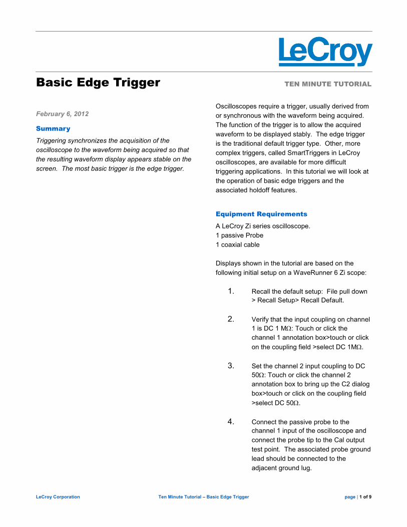
9. The scope display should appear as shown in Figure 1.
10. Press the Normal button in the front panel trigger control group.
This completes the initial setup.
Figure 1: The initial setup of the oscilloscope showing the 1 MHz cal signal in channel 1
and the 5 MHz FastEdge signal in channel 2
Basic Edge Triggering
With edge triggering the scope is triggered when the source trace crosses the trigger threshold level with the user
specified slope (positive or negative).
Turn off channel 2 by using the front panel push button labeled 2 or by touching the C2 trace annotation box to
display the C2 dialog box and then un-checking the Trace On check box.
Bring up the Trigger Setup dialog box by pressing the Trigger Setup button on the front panel or by touching the
Trigger Annotation box. The Trigger dialog box should be setup similar to Figure 2.
LeCroy Corporation Ten Minute Tutorial – Basic Edge Trigger page | 3 of 9
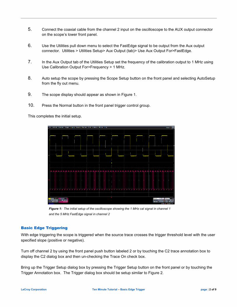
Figure 2: The Trigger dialog box
The Trigger dialog box is used to control the trigger setup. On the left hand side there is a selection for the trigger
type. By default the Edge trigger type is selected. The other trigger types are specialized SmartTriggers which
are discussed in other tutorials. We will be using only edge trigger in this tutorial.
The current scope settings are using channel 1 (C1) as the source of the trigger with a trigger threshold level of
nominally 494 mV and a positive slope. These settings are summarized in the trigger icon on the right side of the
dialog box and in the trigger annotation box.
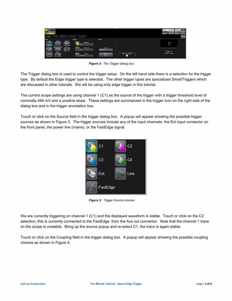
Touch or click on the Source field in the trigger dialog box. A popup will appear showing the possible trigger
sources as shown in Figure 3. The trigger sources include any of the input channels, the Ext input connector on
the front panel, the power line (mains), or the FastEdge signal.
Figure 3: Trigger Source choices
We are currently triggering on channel 1 (C1) and the displayed waveform is stable. Touch or click on the C2
selection, this is currently connected to the FastEdge from the Aux out connector. Note that the channel 1 trace
on the scope is unstable. Bring up the source popup and re-select C1, the trace is again stable.
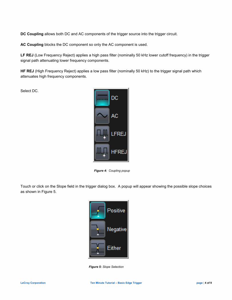
Touch or click on the Coupling field in the trigger dialog box. A popup will appear showing the possible coupling
choices as shown in Figure 4.
LeCroy Corporation Ten Minute Tutorial – Basic Edge Trigger page | 4 of 9
DC Coupling allows both DC and AC components of the trigger source into the trigger circuit.
AC Coupling blocks the DC component so only the AC component is used.
LF REJ (Low Frequency Reject) applies a high pass filter (nominally 50 kHz lower cutoff frequency) in the trigger
signal path attenuating lower frequency components.
HF REJ (High Frequency Reject) applies a low pass filter (nominally 50 kHz) to the trigger signal path which
attenuates high frequency components.
Select DC.
Figure 4: Coupling popup
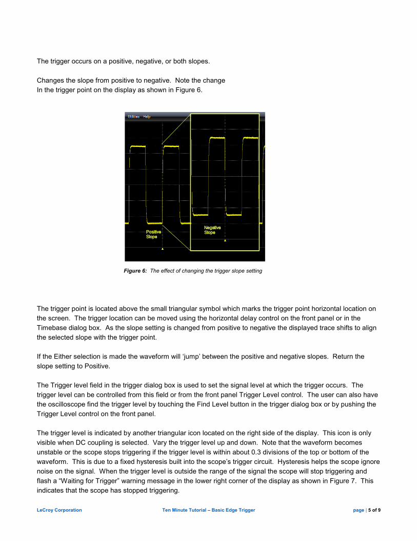
Touch or click on the Slope field in the trigger dialog box. A popup will appear showing the possible slope choices
as shown in Figure 5.
Figure 5: Slope Selection
LeCroy Corporation Ten Minute Tutorial – Basic Edge Trigger page | 5 of 9
The trigger occurs on a positive, negative, or both slopes.
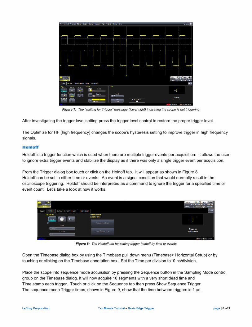
Changes the slope from positive to negative. Note the change
In the trigger point on the display as shown in Figure 6.
Figure 6: The effect of changing the trigger slope setting
The trigger point is located above the small triangular symbol which marks the trigger point horizontal location on
the screen. The trigger location can be moved using the horizontal delay control on the front panel or in the
Timebase dialog box. As the slope setting is changed from positive to negative the displayed trace shifts to align
the selected slope with the trigger point.
If the Either selection is made the waveform will ‘jump’ between the positive and negative slopes. Return the
slope setting to Positive.
The Trigger level field in the trigger dialog box is used to set the signal level at which the trigger occurs. The
trigger level can be controlled from this field or from the front panel Trigger Level control. The user can also have
the oscilloscope find the trigger level by touching the Find Level button in the trigger dialog box or by pushing the
Trigger Level control on the front panel.
The trigger level is indicated by another triangular icon located on the right side of the display. This icon is only
visible when DC coupling is selected. Vary the trigger level up and down. Note that the waveform becomes
unstable or the scope stops triggering if the trigger level is within about 0.3 divisions of the top or bottom of the
waveform. This is due to a fixed hysteresis built into the scope’s trigger circuit. Hysteresis helps the scope ignore
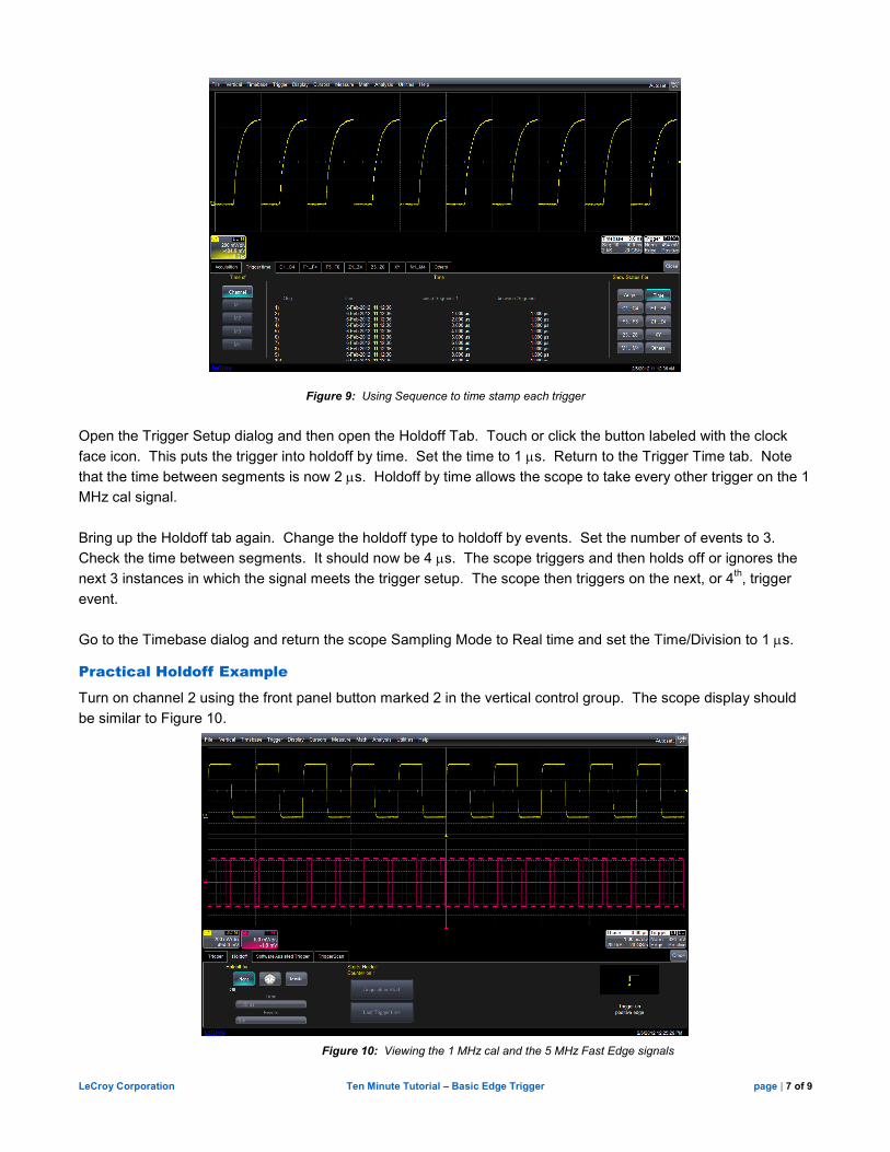
noise on the signal. When the trigger level is outside the range of the signal the scope will stop triggering and
flash a “Waiting for Trigger” warning message in the lower right corner of the display as shown in Figure 7. This
indicates that the scope has stopped triggering.
LeCroy Corporation Ten Minute Tutorial – Basic Edge Trigger page | 6 of 9
Figure 7: The “waiting for Trigger” message (lower right) indicating the scope is not triggering
After investigating the trigger level setting press the trigger level control to restore the proper trigger level.
The Optimize for HF (high frequency) changes the scope’s hysteresis setting to improve trigger in high frequency
signals.
Holdoff
Holdoff is a trigger function which is used when there are multiple trigger events per acquisition. It allows the user
to ignore extra trigger events and stabilize the display as if there was only a single trigger event per acquisition.
From the Trigger dialog box touch or click on the Holdoff tab. It will appear as shown in Figure 8.
Holdoff can be set in either time or events. An event is a signal condition that would normally result in the
oscilloscope triggering. Holdoff should be interpreted as a command to ignore the trigger for a specified time or
event count. Let’s take a look at how it works.
Figure 8: The Holdoff tab for setting trigger holdoff by time or events
Open the Timebase dialog box by using the Timebase pull down menu (Timebase> Horizontal Setup) or by
touching or clicking on the Timebase annotation box. Set the Time per division to10 ns/division.
Place the scope into sequence mode acquisition by pressing the Sequence button in the Sampling Mode control
group on the Timebase dialog. It will now acquire 10 segments with a very short dead time and
Time stamp each trigger. Touch or click on the Sequence tab then press Show Sequence Trigger.
The sequence mode Trigger times, shown in Figure 9, show that the time between triggers is 1 µs.
LeCroy Corporation Ten Minute Tutorial – Basic Edge Trigger page | 7 of 9
Figure 9: Using Sequence to time stamp each trigger
Open the Trigger Setup dialog and then open the Holdoff Tab. Touch or click the button labeled with the clock
face icon. This puts the trigger into holdoff by time. Set the time to 1 µs. Return to the Trigger Time tab. Note
that the time between segments is now 2 µs. Holdoff by time allows the scope to take every other trigger on the 1
MHz cal signal.
Bring up the Holdoff tab again. Change the holdoff type to holdoff by events. Set the number of events to 3.
Check the time between segments. It should now be 4 µs. The scope triggers and then holds off or ignores the
next 3 instances in which the signal meets the trigger setup. The scope then triggers on the next, or 4th, trigger
event.
Go to the Timebase dialog and return the scope Sampling Mode to Real time and set the Time/Division to 1 µs.
Practical Holdoff Example
Turn on channel 2 using the front panel button marked 2 in the vertical control group. The scope display should
be similar to Figure 10.
Figure 10: Viewing the 1 MHz cal and the 5 MHz Fast Edge signals
LeCroy Corporation Ten Minute Tutorial – Basic Edge Trigger page | 8 of 9
Channel 1 is acquiring the 1 MHz cal signal and channel 2 displays the 5 MHz FastEdge signal. In the current
configuration the scope is triggering on the 1 MHz signal in channel 1. Since the signal on channel 2 is
harmonically related to the trigger it also appears stable.
Change the trigger source to be channel 2. The trace on channel 2 will be stable but that on channel 1 is now
unstable. This happens because there are five times as many possible trigger events on channel 2 for every one
on channel 1 so when the scope triggers the waveform on channel 1 can be in any of five different phases and it
appears to be unstable.
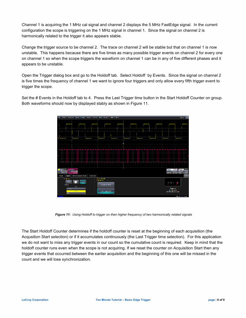
Open the Trigger dialog box and go to the Holdoff tab. Select Holdoff by Events. Since the signal on channel 2
is five times the frequency of channel 1 we want to ignore four triggers and only allow every fifth trigger event to
trigger the scope.
Set the # Events in the Holdoff tab to 4. Press the Last Trigger time button in the Start Holdoff Counter on group.
Both waveforms should now by displayed stably as shown in Figure 11.
Figure 11: Using Holdoff to trigger on then higher frequency of two harmonically related signals
The Start Holdoff Counter determines if the holdoff counter is reset at the beginning of each acquisition (the
Acqusition Start selection) or if it accumulates continuously (the Last Trigger time selection). For this application
we do not want to miss any trigger events in our count so the cumulative count is required. Keep in mind that the
holdoff counter runs even when the scope is not acquiring. If we reset the counter on Acquisition Start then any
trigger events that occurred between the earlier acquisition and the beginning of this one will be missed in the
count and we will lose synchronization.
LeCroy Corporation Ten Minute Tutorial – Basic Edge Trigger page | 9 of 9
This is a simple use of holdoff. In general, holdoff can be used in several different applications:
1. When there are multiple trigger events in a signal.
2. Triggering on the higher frequency of two harmonically related signals (e.g. output of a PLL frequency
multiplier while looking at both the output and input.
3. Trigger at a fixed time delay. (e.g. trigger a scope every 10 seconds for a data logging application).
4. Trigger on the clock repetition of a pseudo random process with a known, fixed number of states
As you have seen Holdoff greatly improves the versatility of the basic edge trigger.
This completes this tutorial.