Embed Size (px)
Citation preview
20 Commercial St Branford, CT 06405
Phone: (203) 208-0806 Fax: (203) 488-4820
December 18, 2014
Connecticut Siting Council Ten Franklin Square New Britain, CT 06051 Attn: Ms. Melanie Bachman, Executive Director
Re: Notice of Exempt Modification Application 585 South Main Street Naugatuck, CT 06770 Dear Ms. Bachman,
On behalf of New Cingular Wireless PCS, LLC ("AT&T"), enclosed for filing are an original and two (2) copies of
AT&T’s Notice of Exempt Modification for Proposed Modifications to an Existing Telecommunications Facility located at
the above-referenced site. I also enclose herewith a check in the amount of $625.00 representing the fee for the Notice of Exempt
Modification.
If you have any questions, please feel free to contact me.
Thank you, By: _______________________________________________ Name: David Weisman Vertical Development LLC 20 Commercial Street Branford, CT 06405 Phone – 401-743-9011 Fax – 401-633-6202 [email protected] CC: Robert A. Mezzo, Mayor The Office LLC
Naugatuck Town Hall 585 South Main Street 229 Church Street Naugatuck, CT 06770 Naugatuck, CT 06770 Attn.: Owner
[email protected] (electronic copy)
CT2166‐Naugatuck CSC Cover Letter
Notice of Exempt Modification
585 South Main Street Naugatuck, CT 06770
New Cingular Wireless PCS, LLC ("AT&T") submits this Notice of Exempt
Modification to the Connecticut Siting Council ("Council") pursuant to Sections
16-50j-73 and 16-50j-72(b) of the Regulations of Connecticut State Agencies
(“Regulations”) in connection with AT&T’s planned modification of antennas
and associated equipment on an existing 49’ monopole located at 585 South
Main Street, in the Town of Naugatuck, Connecticut. More particularly, AT&T
plans to upgrade this site by adding LTE technology to its facilities. The
proposed modifications will not increase the tower height, cause a significant
adverse change or alteration in the physical or environmental characteristics of
the site, extend the boundaries of the tower site, increase noise levels at the
tower site boundary by six (6) decibels, add radio frequency sending or
receiving capability which increases the total radio frequency electromagnetic
radiation power density measured at the tower site boundary to or above the
standard adopted by the Federal Communications Commission pursuant to
Section 704 of the Telecommunications Act of 1996, as amended, and the State
Department of Energy and Environmental Protection, pursuant to Section 22a-
162 of the Connecticut General Statutes, or impair the structural integrity of
the facility, as determined in a certification provided by a professional engineer
licensed in Connecticut.
To better meet the growing voice and data demands of its wireless
customers, AT&T is upgrading their network nationwide to include LTE
technology, which will provide faster service and better overall performance.
Pursuant to the LTE technology upgrade at this site, AT&T will add panel
antennas, install RRHs, and install related equipment to its equipment area
within the fenced tower compound.
CT2166 – 585 South Main St., Naugatuck December 19, 2014
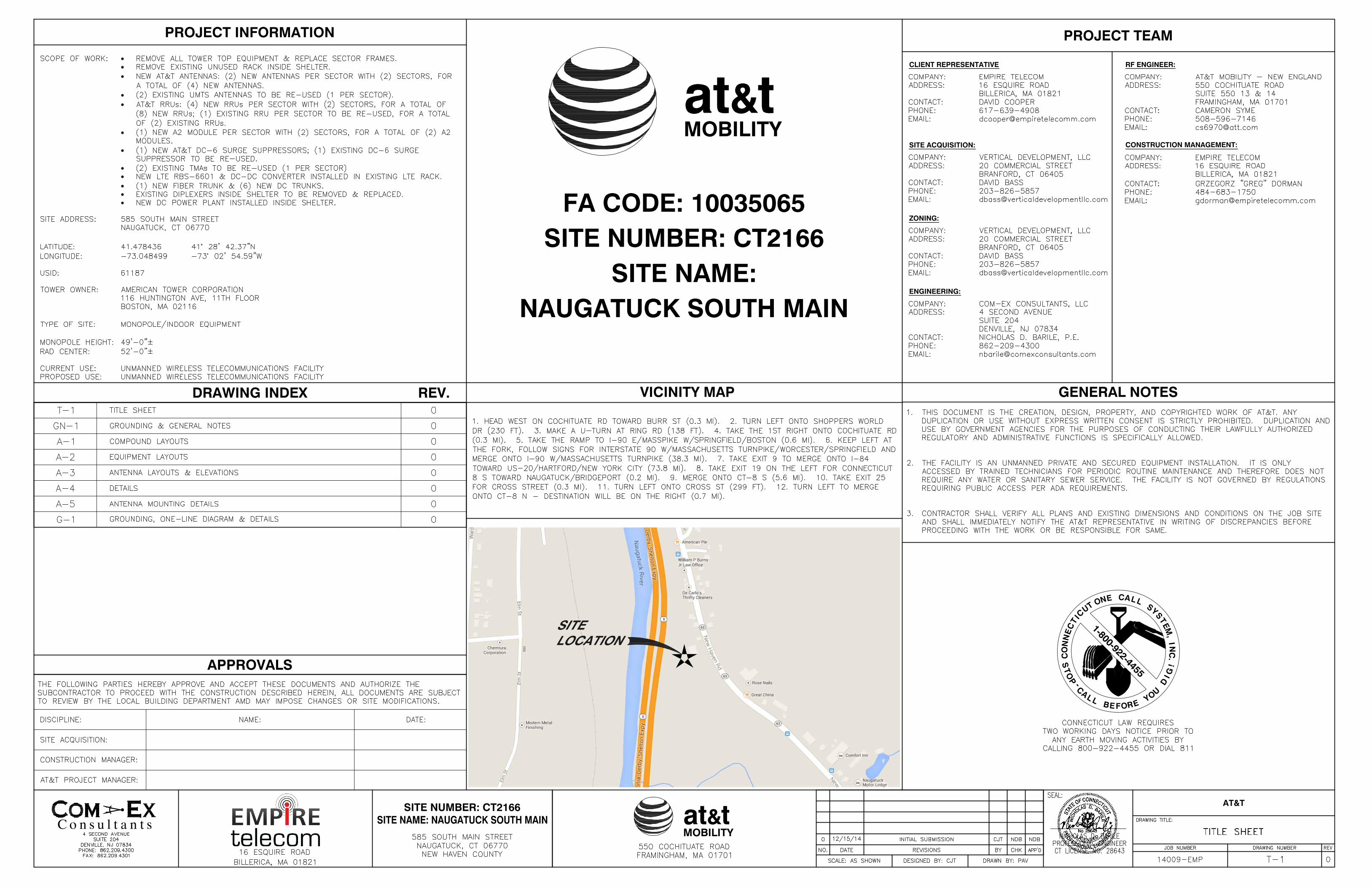
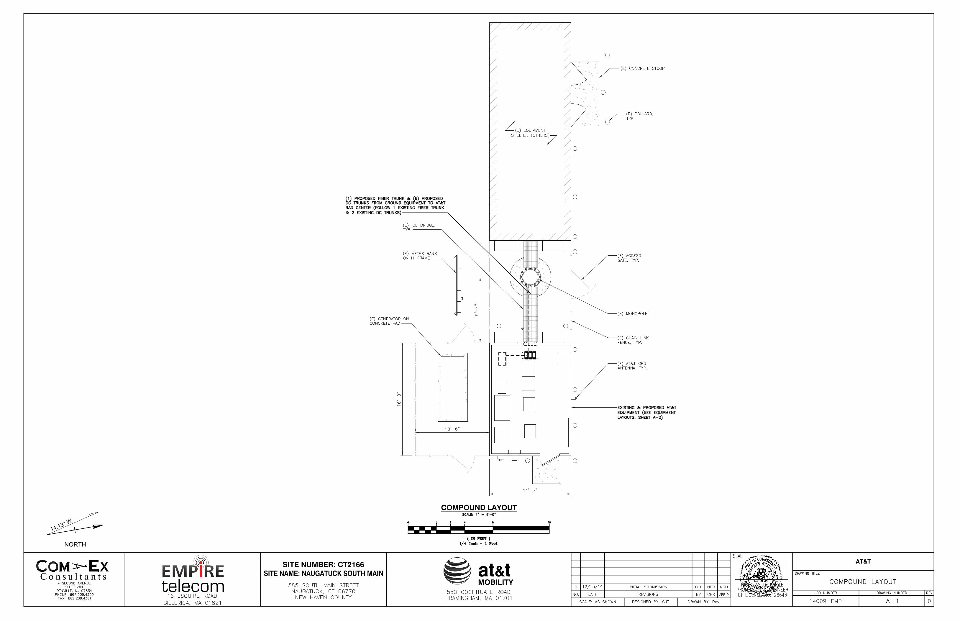
The existing 49’ monopole located at 585 South Main Street, in the Town
of Naugatuck, Connecticut (lat. 41° 28’ 42.37”, long. -73° 2’ 54.60”) is owned by
American Tower Corporation, a Delaware corporation. AT&T’s existing facility
is located within the Landlord’s existing fenced compound. AT&T currently has
six (6) panel antennas (two (2) per sector) with a centerline of 52’ installed on
the tower. AT&T's base station equipment is located adjacent to the base of the
tower within the fenced compound. A site plan depicting this is attached.
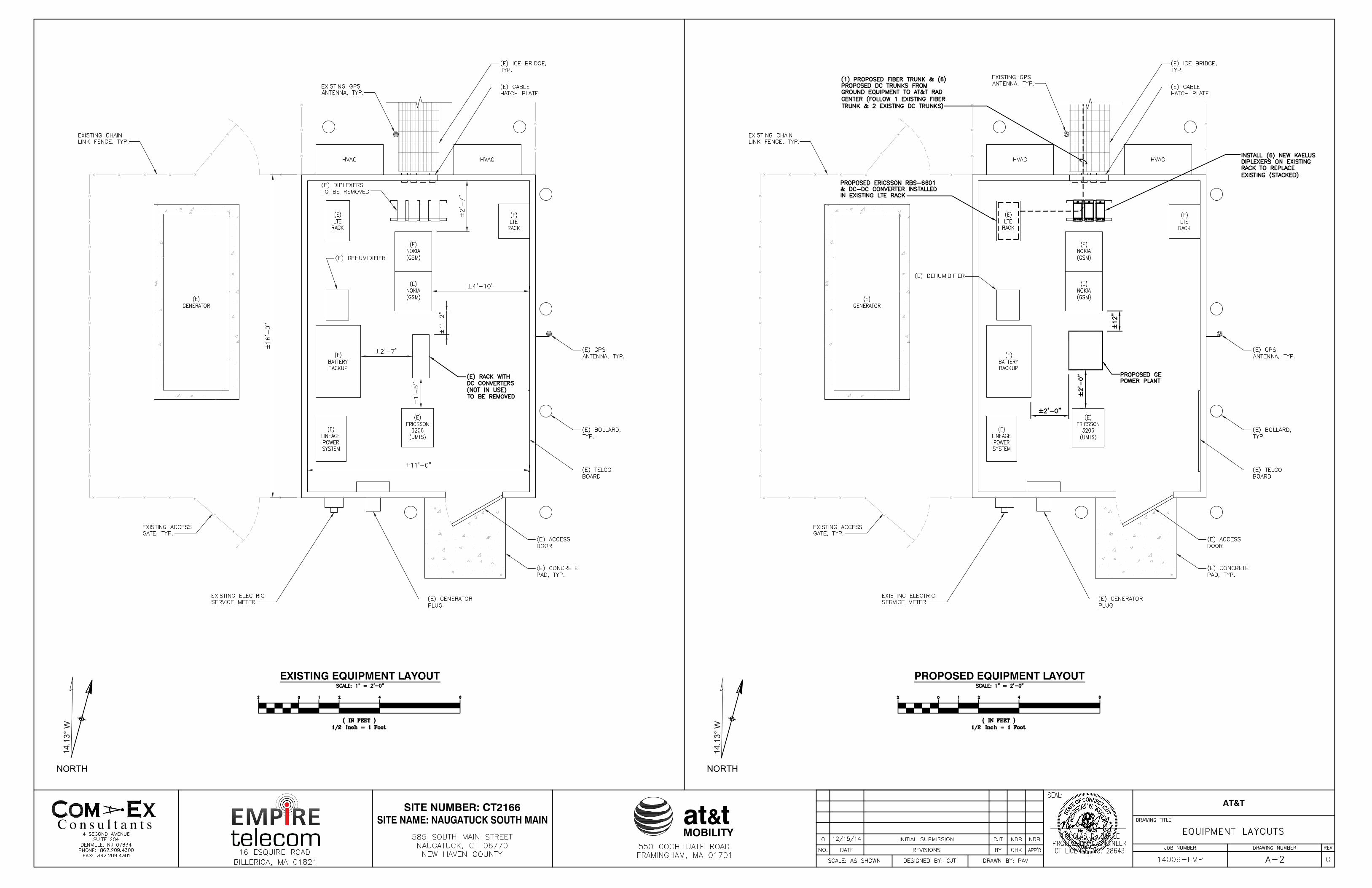
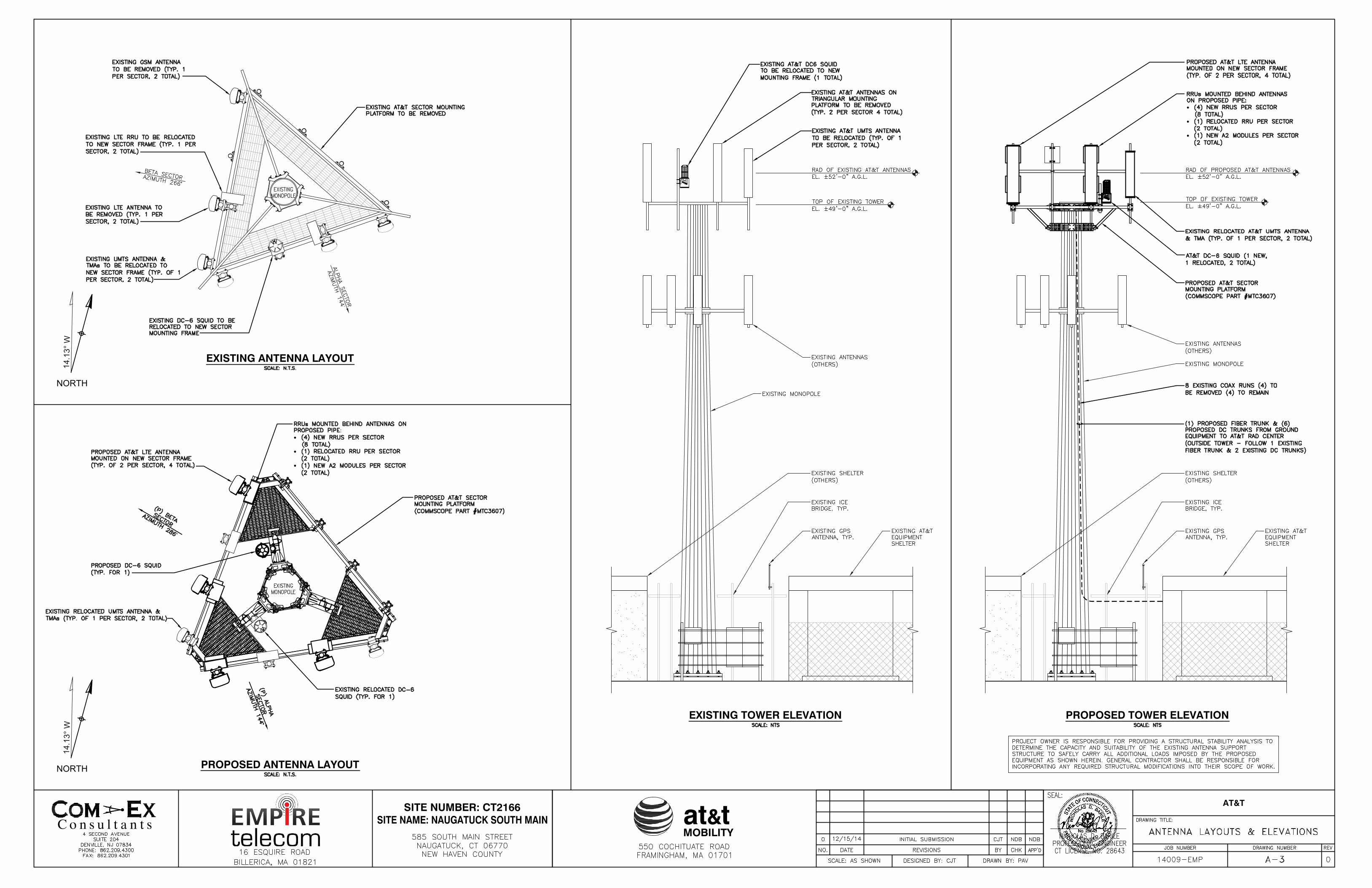
AT&T plans to remove all existing equipment and install a new
Commscope MTC3607 platform mount. AT&T will relocate to the new platform
two (2) existing Powerwave 7777.00 panel antennas (one (1) per sector), two (2)
TMAs, two (2) Ericsson RRUS-11 (one (1) per sector) which will be connected
and located behind the Powerwave 7777.00 panel antennas, one (1) DC-6
Surge Suppressors.
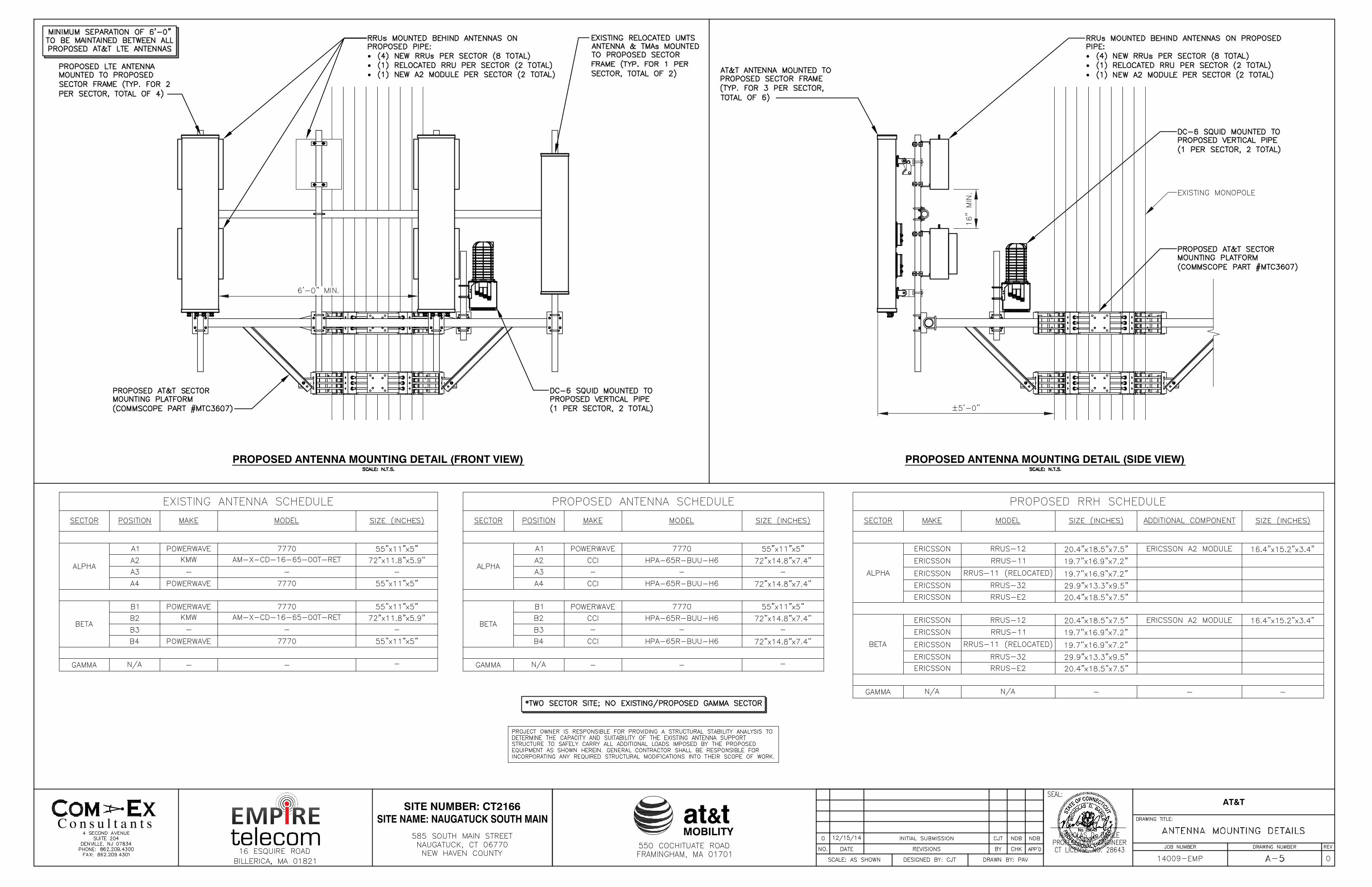
AT&T plans to add to the new platform four (4) CCI OPA-65R-LCUU-H6
panel antennas (2 per sector), four (4) Powerwave Allgon CM1007-DBXBC-003
Diplexers, (2) RRUS-12 (1 per sector), two (2) Ericsson A2 modules (1) per
sector (attached behind each respective RRU-12), two (2) additional RRUS-11 (1
per sector), two (2) RRUS-32 (1 per sector), and two (2) RRUS-E2 (1 per sector)
and will add one (1) new Raycap DC-6 Surge Suppressor. The height of the
tower will not be increased and all antennas, surge suppressors, and RRHs will
be installed at the 52’ centerline.
Within the existing equipment shelter AT&T also plans to install a new
DC-DC Converter and Ericsson RBS 6601 in an existing LTE Rack, remove and
replace an existing rack with a new GE Power Plant, remove existing diplexers
on an existing rack and replace them with six (6) new Kaelus Diplexers. Finally,
AT&T will be removing four (4) existing coax runs (leaving four (4) coax runs)
and adding one (1) fiber trunk and six (6) DC Trunks from the ground
equipment to the AT&T Rad Center outside the tower following one (1) existing
fiber trunk and two (2) existing DC Trunks. The compound’s boundaries will
not need to be extended. The proposed modifications will not cause a
significant adverse change or alteration in the physical or environmental
CT2166 – 585 South Main St., Naugatuck December 19, 2014
characteristics of the site, since it is already a telecommunications installation
and the modifications will be compatible with this. Other than brief,
construction-related noise, these modifications will not increase noise levels at
the tower site boundary by six (6) decibels.
The proposed modifications will not add radio frequency sending or
receiving capability which increases the total radio frequency electromagnetic
radiation power density measured at the tower site boundary to or above the
standard adopted by the Federal Communications Commission pursuant to
Section 704 of the Telecommunications Act of 1996, as amended, and the State
Department of Energy and Environmental Protection, pursuant to Section 22a-
162 of the Connecticut General Statutes. A radio frequency emissions analysis
prepared by EBI Consulting concludes that the proposed final configuration
(including other carriers on the tower) will emit 54.87% of the allowable FCC
established general public limits sampled at the ground level (see page 1 and
the 6th page of Radio Frequency Emissions Analysis Report Evaluation of
Human Exposure Potential to Non-Ionizing Emissions (the “MPE” Assessment)
dated December 11, 2014). Emissions values for additional carriers were
based upon values listed in Connecticut Siting Council active database (see the
2nd and 6 page of the MPE Assessment dated December 11, 2014). The
information used in the report was analyzed as a percentage of current
Maximum Permissible Exposure (%MPE) as listed in the FCC OET Bulletin 65
Edition 97-01 and ANSI/IEEE Std C95.1 (see the 2nd page of the MPE
Assessment.
The proposed modifications will not impair the structural integrity of the
facility. On AT&T’s behalf, American Tower Corporation commissioned Semaan
Engineering Solutions to perform a structural analysis of the tower to verify
that it can support the proposed loading. The structure and foundation were
found to meet the specified TIA requirements and deemed adequate to support
the existing and proposed loading, and was rated at 66% (see page 1 of the
Structural Analysis Report dated November 25, 2014.)
CT2166 – 585 South Main St., Naugatuck December 19, 2014
CT2166 – 585 South Main St., Naugatuck December 19, 2014
In conclusion, AT&T’s proposed modifications do not constitute a
modification subject to the Council’s review because AT&T will not change the
height of the tower, will not extend the boundaries of the compound, will not
cause a significant adverse change or alteration in the physical or
environmental characteristics of the site, will not increase the noise levels at
the site, will not increase the total radio frequency electromagnetic radiation
power density at the site to levels above applicable standards, and will not
impair the structural integrity of the facility. Therefore, AT&T respectfully
requests that the Council acknowledge that this Notice of Exempt Modification
meets the Council’s exemption criteria.
at&tMOBILITY
SITE NUMBER: CT2166 AT&T
VICINITY MAP
PROJECT TEAMPROJECT INFORMATION
at&tMOBILITY
FA CODE: 10035065SITE NUMBER: CT2166
SITE NAME:
DRAWING INDEX REV.
APPROVALS
GENERAL NOTES
NAUGATUCK SOUTH MAIN
CLIENT REPRESENTATIVE
SITE ACQUISITION:
ZONING:
ENGINEERING:
RF ENGINEER:
CONSTRUCTION MANAGEMENT:
at&tMOBILITY
SITE NUMBER: CT2166 AT&T
at&tMOBILITY
SITE NUMBER: CT2166 AT&T
COMPOUND LAYOUT
NORTH
1
4
.
1
3
°
W
at&tMOBILITY
SITE NUMBER: CT2166 AT&T
EXISTING EQUIPMENT LAYOUT PROPOSED EQUIPMENT LAYOUT
NORTH
14.13° W
NORTH
14.13° W
at&tMOBILITY
SITE NUMBER: CT2166 AT&T
EXISTING ANTENNA LAYOUT
PROPOSED ANTENNA LAYOUT
EXISTING TOWER ELEVATION PROPOSED TOWER ELEVATION
NORTH
14.13° W
NORTH
14.13° W
at&tMOBILITY
SITE NUMBER: CT2166 AT&T
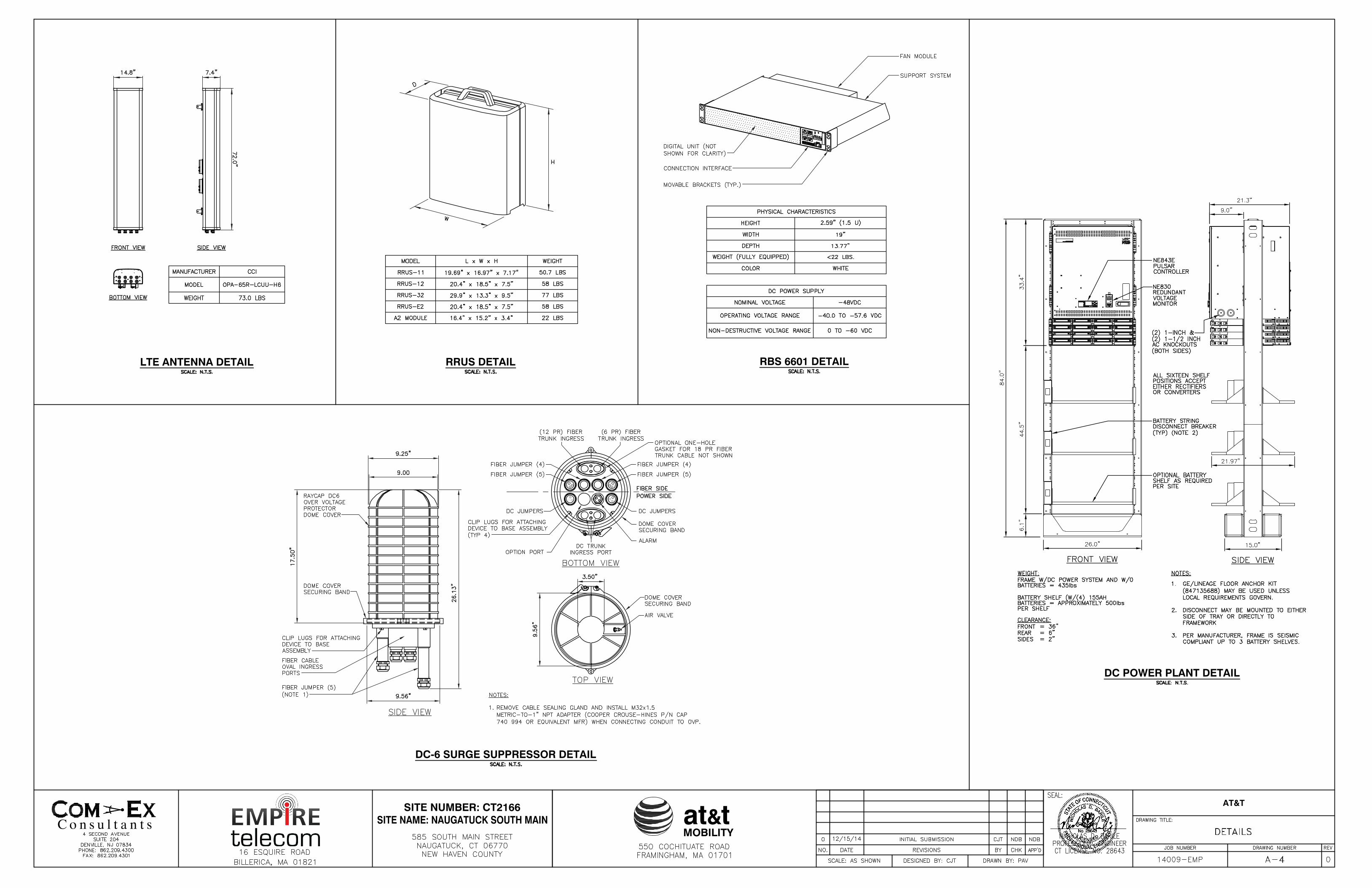
LTE ANTENNA DETAIL RRUS DETAIL
DC-6 SURGE SUPPRESSOR DETAIL
RBS 6601 DETAIL
DC POWER PLANT DETAIL
at&tMOBILITY
SITE NUMBER: CT2166 AT&T
PROPOSED ANTENNA MOUNTING DETAIL (FRONT VIEW) PROPOSED ANTENNA MOUNTING DETAIL (SIDE VIEW)
at&tMOBILITY
SITE NUMBER: CT2166 AT&T
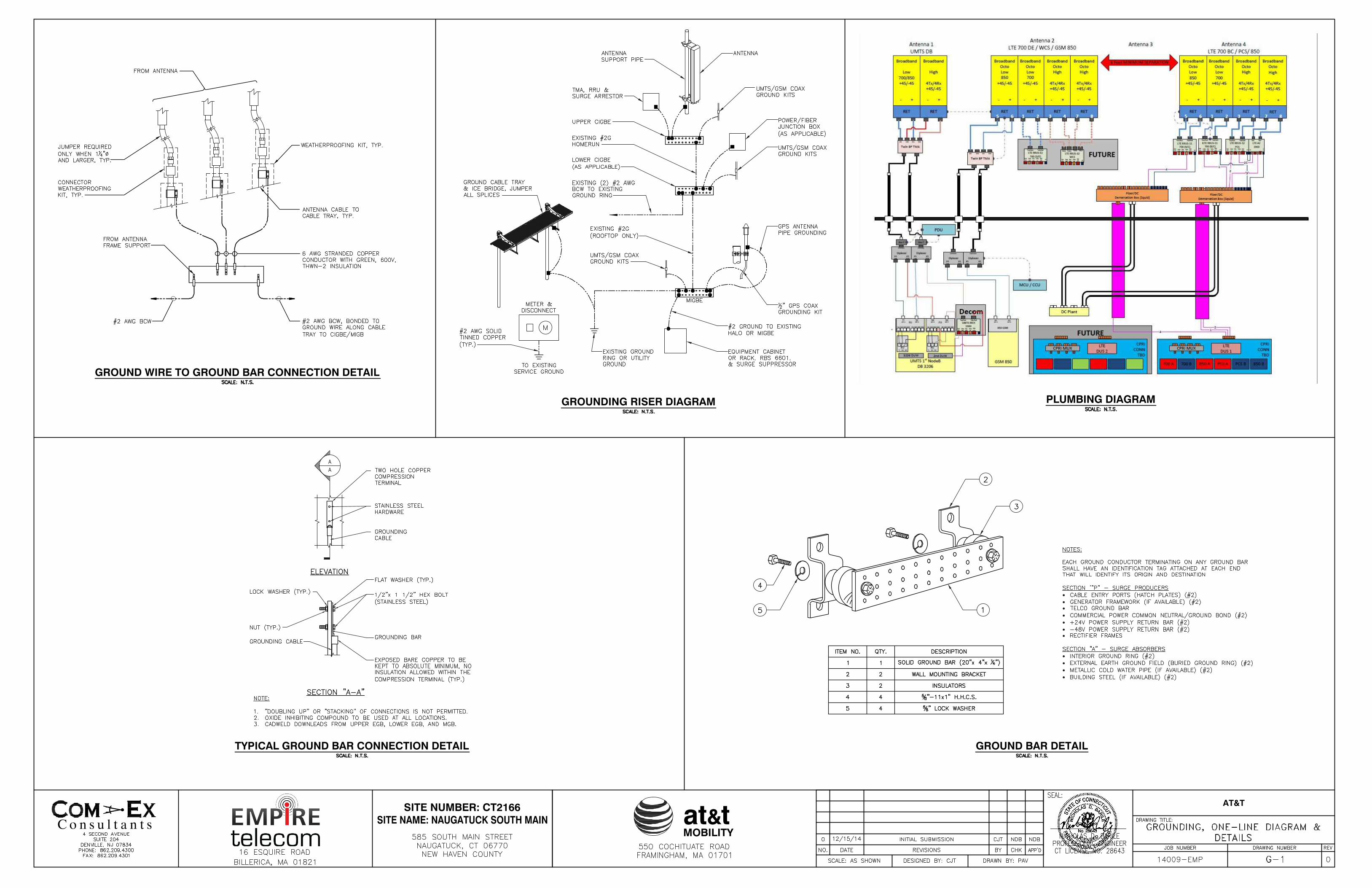
PLUMBING DIAGRAM
GROUND WIRE TO GROUND BAR CONNECTION DETAIL
GROUND BAR DETAIL
GROUNDING RISER DIAGRAM
TYPICAL GROUND BAR CONNECTION DETAIL
Semaan Engineering Solutions Holdings s 1079 N 205th St s Elkhorn, NE 68022 s 402-289-1888
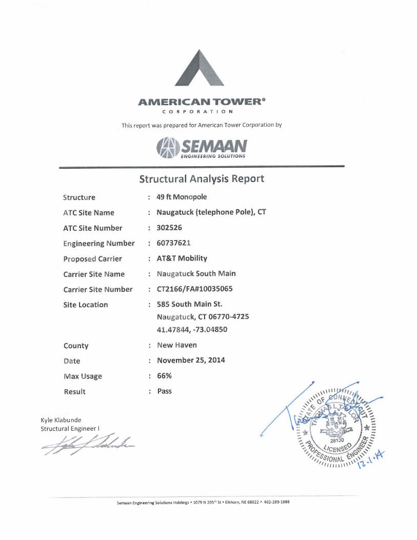
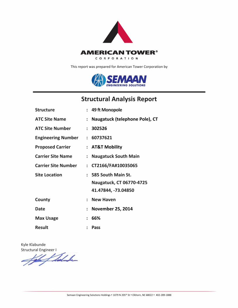
This report was prepared for American Tower Corporation by
Structural Analysis ReportStructure : 49 ft Monopole
ATC Site Name : Naugatuck (telephone Pole), CT
ATC Site Number : 302526
Engineering Number : 60737621
Proposed Carrier : AT&T Mobility
Carrier Site Name : Naugatuck South Main
Carrier Site Number : CT2166/FA#10035065
Site Location : 585 South Main St. Naugatuck, CT 06770-4725 41.47844, -73.04850
County : New Haven
Date : November 25, 2014
Max Usage : 66%
Result : Pass
Kyle KlabundeStructural Engineer I
Eng. Number 60737621November 25, 2014
Semaan Engineering Solutions Holdings s 1079 N 205th St s Elkhorn, NE 68022 s 402-289-1888
Table of Contents
Introduction .................................................................................................................................... 1
Supporting Documents .................................................................................................................... 1
Analysis ........................................................................................................................................... 1
Conclusion....................................................................................................................................... 1
Existing and Reserved Equipment..................................................................................................... 2
Equipment to be Removed............................................................................................................... 2
Proposed Equipment ....................................................................................................................... 2
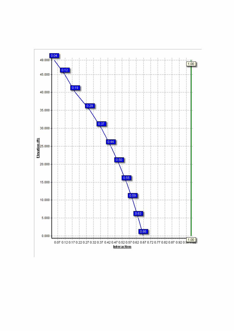
Structure Usages .............................................................................................................................. 3
Foundations ..................................................................................................................................... 3
Deflection, Twist, and Sway............................................................................................................... 3
Standard Conditions ......................................................................................................................... 4
Calculations ......................................................................................................................... Attached
Eng. Number 60737621November 25, 2014
Page 1
Semaan Engineering Solutions Holdings s 1079 N 205th St s Elkhorn, NE 68022 s 402-289-1888
Introduction
The purpose of this report is to summarize results of a structural analysis performed on the 49 ft monopole to reflect the change in loading by AT&T Mobility.
Supporting Documents
Tower Drawings EEI Job #11696, dated January 22, 2001Foundation Drawing EEI Job #11696, dated June 5, 2003Geotechnical Report CET Project #07729-76, dated March 28, 2003Modifications N/A
Analysis
The tower was analyzed using American Tower Corporation’s tower analysis software. This program considers an elastic three-dimensional model and second-order effects per ANSI/TIA-222.
Basic Wind Speed: 100 mph (3-Second Gust)Basic Wind Speed w/ Ice: 50 mph (3-Second Gust) w/ 3/4" radial ice concurrentCode: ANSI/TIA-222-G / 2003 IBC w/ 2005 CT Supplement & 2009 CT AmendmentStructure Class: IIExposure Category: BTopographic Category: 1
Conclusion
Based on the analysis results, the structure meets the requirements per the applicable codes listed above. The tower and foundation can support the equipment as described in this report.
If you have any questions or require additional information, please contact American Tower via email at [email protected]. Please include the American Tower site name, site number, and engineering number in the subject line for any questions.
Eng. Number 60737621November 25, 2014
Page 2
Semaan Engineering Solutions Holdings s 1079 N 205th St s Elkhorn, NE 68022 s 402-289-1888
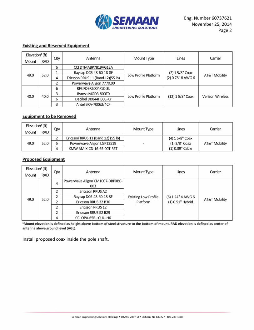
Existing and Reserved Equipment
Elevation¹ (ft)Mount RAD
Qty Antenna Mount Type Lines Carrier
6 CCI DTMABP7819VG12A1 Raycap DC6-48-60-18-8F4 Ericsson RRUS 11 (Band 12)(55 lb)
49.0 52.0
2 Powerwave Allgon 7770.00
Low Profile Platform (2) 1 5/8" Coax(2) 0.78" 8 AWG 6 AT&T Mobility
6 RFS FD9R6004/1C-3L3 Rymsa MGD3-800T06 Decibel DB844H80E-XY
40.0 40.0
3 Antel BXA-70063/4CF
Low Profile Platform (12) 1 5/8" Coax Verizon Wireless
Equipment to be Removed
Elevation¹ (ft)Mount RAD
Qty Antenna Mount Type Lines Carrier
2 Ericsson RRUS 11 (Band 12) (55 lb)5 Powerwave Allgon LGP1351949.0 52.04 KMW AM-X-CD-16-65-00T-RET
-(4) 1 5/8" Coax(1) 3/8" Coax
(1) 0.39" CableAT&T Mobility
Proposed Equipment
Elevation¹ (ft)Mount RAD
Qty Antenna Mount Type Lines Carrier
4 Powerwave Allgon CM1007-DBPXBC-003
2 Ericsson RRUS A22 Raycap DC6-48-60-18-8F2 Ericsson RRUS 32 B302 Ericsson RRUS 122 Ericsson RRUS E2 B29
49.0 52.0
4 CCI OPA-65R-LCUU-H6
Existing Low Profile Platform
(6) 1.24" 4 AWG 6(1) 0.51" Hybrid AT&T Mobility
1Mount elevation is defined as height above bottom of steel structure to the bottom of mount, RAD elevation is defined as center of antenna above ground level (AGL).
Install proposed coax inside the pole shaft.
Eng. Number 60737621November 25, 2014
Page 3
Semaan Engineering Solutions Holdings s 1079 N 205th St s Elkhorn, NE 68022 s 402-289-1888
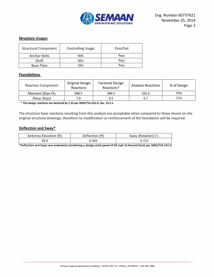
Structure Usages
Structural Component Controlling Usage Pass/Fail
Anchor Bolts 46% PassShaft 66% Pass
Base Plate 59% Pass
Foundations
Reaction Component Original Design Reactions
Factored Design Reactions* Analysis Reactions % of Design
Moment (Kips-Ft) 288.5 389.5 291.6 75%Shear (Kips) 7.0 9.5 6.7 71%
* The design reactions are factored by 1.35 per ANSI/TIA-222-G, Sec. 15.5.1
The structure base reactions resulting from this analysis are acceptable when compared to those shown on the original structure drawings, therefore no modification or reinforcement of the foundation will be required.
Deflection and Sway*
Antenna Elevation (ft) Deflection (ft) Sway (Rotation) (°)49.0 0.369 -0.722
*Deflection and Sway was evaluated considering a design wind speed of 60 mph (3-Second Gust) per ANSI/TIA-222-G
Semaan Engineering Solutions Holdings s 1079 N 205th St s Elkhorn, NE 68022 s 402-289-1888
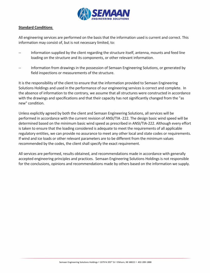
Standard Conditions
All engineering services are performed on the basis that the information used is current and correct. This information may consist of, but is not necessary limited, to:
-- Information supplied by the client regarding the structure itself, antenna, mounts and feed line loading on the structure and its components, or other relevant information.
-- Information from drawings in the possession of Semaan Engineering Solutions, or generated by field inspections or measurements of the structure.
It is the responsibility of the client to ensure that the information provided to Semaan Engineering Solutions Holdings and used in the performance of our engineering services is correct and complete. In the absence of information to the contrary, we assume that all structures were constructed in accordance with the drawings and specifications and that their capacity has not significantly changed from the "as new" condition.
Unless explicitly agreed by both the client and Semaan Engineering Solutions, all services will be performed in accordance with the current revision of ANSI/TIA -222. The design basic wind speed will be determined based on the minimum basic wind speed as prescribed in ANSI/TIA-222. Although every effort is taken to ensure that the loading considered is adequate to meet the requirements of all applicable regulatory entities, we can provide no assurance to meet any other local and state codes or requirements. If wind and ice loads or other relevant parameters are to be different from the minimum values recommended by the codes, the client shall specify the exact requirement.
All services are performed, results obtained, and recommendations made in accordance with generally accepted engineering principles and practices. Semaan Engineering Solutions Holdings is not responsible for the conclusions, opinions and recommendations made by others based on the information we supply.
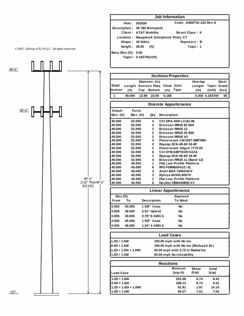
Job Information
Pole :
Description :
Location :
Height :
Client :
Shape :
302526
49' EEI Monopole
AT&T Mobility
Naugatuck (telephone Pole), CT
18 Sides
49.00
Taper: 0.183700(in/ft)
(ft)
0.00© 2007 - 2014 by ATC IP LLC. All rights reserv ed.
Base Elev (ft):
Code: ANSI/TIA-222 Rev G
Exposure :
Struct Class :
Topo :
II
B
1
Sections Properties
Section (ft)LengthShaft
Diam eter (in)Accross Flats
(in)TopThick Length
(in)
Overlap SteelGrade(ksi)Bottom
JointType
Taper(in/ft)
1 49.000 13.99 23.00 0.188 0.000 650.183700
Discrete Appurtenance
Attach(ft) DescriptionQtyElev
ForceElev (ft)
49.000 CCI OPA-65R-LCUU-H6452.00049.000 Ericsson RRUS E2 B29252.00049.000 Ericsson RRUS 12252.00049.000 Ericsson RRUS 32 B30252.00049.000 Ericsson RRUS A2252.00049.000 Pow erw ave CM1007-DBPXBC-452.00049.000 Raycap DC6-48-60-18-8F252.00049.000 Pow erw ave Allgon 7770.00252.00049.000 CCI DTMABP7819VG12A652.00049.000 Raycap DC6-48-60-18-8F152.00049.000 Ericsson RRUS 11 (Band 12)452.00049.000 Flat Low Profile Platform149.00040.000 RFS FD9R6004/1C-3L640.00040.000 Antel BXA-70063/4CF340.00040.000 Rym sa MGD3-800T0340.00040.000 Flat Low Profile Platform140.00040.000 Decibel DB844H80E-XY640.000
Linear AppurtenanceElev (ft)
From DescriptionToExposedTo Wind
0.000 40.000 1 5/8" Coax No
0.000 49.000 0.51" Hybrid No
0.000 49.000 0.78" 8 AWG 6 No
0.000 49.000 1 5/8" Coax No
0.000 49.000 1.24" 4 AWG 6 No
Load Cases
1.2D + 1.6W 100.00 m ph w ith No Ice
0.9D + 1.6W 100.00 m ph w ith No Ice (Reduced DL)
1.2D + 1.0Di + 1.0Wi 50.00 m ph w ith 0.75 in Radial Ice
1.0D + 1.0W 60.00 m ph Serviceability
Mom ent Shear AxialLoad Case
Reactions
(kip)(kip)(kip-ft)
1.2D + 1.6W 291.58 6.74 8.430.9D + 1.6W 289.13 6.73 6.311.2D + 1.0Di + 1.0Wi 81.91 1.87 14.141.0D + 1.0W 65.27 1.51 7.04
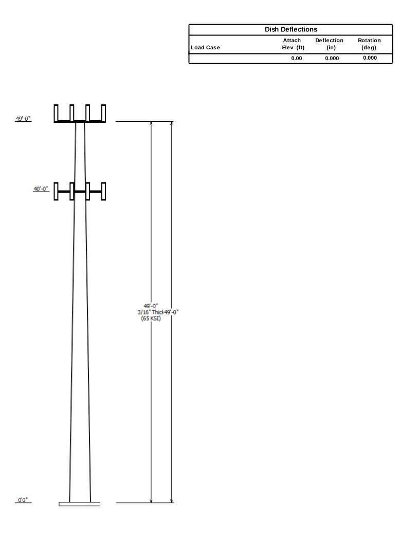
Dish Deflections
AttachElev (ft)Load Case
RotationDeflection(deg)(in)
0.00 0.000 0.000
Pole :11/25/2014 5:05:58 PM
Code:
1Page:
302526Location : Naugatuck (telephone Pole), CT
Height : 49.00 (ft)
Shape : 18 Sides
(in)23.00Base Dia :Base Elev : 0.000 (ft)(in)13.99Top Dia :
Taper : 0.183700 (in/ft) © 2007 - 2014 by ATC IP LLC. All rights reserv ed.
ANSI/TIA-222 Rev GStruct Class : II
BExposure Category :1Topographic Category :
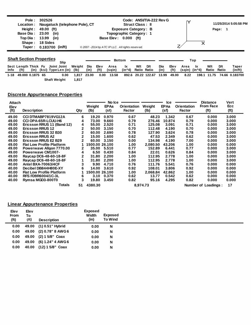
Bottom Slip
TaperD/tW/tIxAreaElevDiaD/tW/tIxAreaElevDiaWeightJointJointFyThickLengthSectRatioRatio(in^4)(sqin)(ft)(in)(lb)Len (in)Type(ksi)(in)(ft)Info (in/ft)RatioRatio(in^4)(sqin)(ft)(in)
Top Shaft Section Properties
49.000 650.1875 23.001-18 0.00 13.991,817 49.000.00 13.58 892.6 8.22 198.120.22 122.67 74.6611.75 0.183700
Shaft Weight 1,817
(ft)OrientationEPAaWeight
No Ice Ice
(lb) (sf) Factor
Discrete Appurtenance Properties
Elev(ft) Description
Weight(lb) (sf)
EPAa OrientationFactor
DistanceFrom Face
(ft)
VertEcc
Qty
Attach
CCI DTMABP7819VG12A49.00 19.20 0.970 0.67 0.67 3.0000.0006 48.23 1.342CCI OPA-65R-LCUU-H649.00 73.00 9.660 0.79 0.79 3.0000.0004 276.46 10.874Ericsson RRUS 11 (Band 12)49.00 55.00 2.520 0.71 0.71 3.0000.0004 125.08 3.091Ericsson RRUS 1249.00 50.00 3.150 0.70 0.70 3.0000.0002 112.48 4.190Ericsson RRUS 32 B3049.00 60.00 2.690 0.78 0.78 3.0000.0002 127.90 3.624Ericsson RRUS A249.00 15.00 1.600 0.62 0.62 3.0000.0002 47.53 2.349Ericsson RRUS E2 B2949.00 60.00 3.150 0.00 7.00 3.0000.0002 134.98 4.190Flat Low Profile Platform49.00 1500.00 26.100 1.00 1.00 0.0000.0001 2,080.50 43.206Powerwave Allgon 7770.0049.00 35.00 5.510 0.77 0.77 3.0000.0002 152.89 6.441Powerwave CM1007-49.00 6.50 0.430 0.84 0.84 3.0000.0004 22.01 0.626Raycap DC6-48-60-18-8F49.00 31.80 2.200 1.00 1.00 3.0000.0002 112.95 2.778Raycap DC6-48-60-18-8F49.00 31.80 2.200 1.00 1.00 3.0000.0001 112.95 2.778Antel BXA-70063/4CF40.00 9.90 4.710 0.76 0.76 0.0000.0003 111.76 5.541Decibel DB844H80E-XY40.00 14.00 3.610 0.92 0.92 0.0000.0006 108.01 3.806Flat Low Profile Platform40.00 1500.00 26.100 1.00 1.00 0.0000.0001 2,068.84 42.862RFS FD9R6004/1C-3L40.00 3.10 0.370 0.62 0.62 0.0000.0006 13.77 0.542Rymsa MGD3-800T040.00 19.80 3.450 0.82 0.82 0.0000.0003 95.16 4.295
4380.30 17Number of Loadings :Totals 51 8,974.73
(ft)(ft)
Linear Appurtenance Properties
DescriptionFrom
ElevTo
Elev
To WindExposed
ExposedWidth
(in)
0.00 N0.00 49.00 (1) 0.51" Hybrid
0.00 N0.00 49.00 (2) 0.78" 8 AWG 6
0.00 N0.00 49.00 (2) 1 5/8" Coax
0.00 N0.00 49.00 (6) 1.24" 4 AWG 6
0.00 N0.00 40.00 (12) 1 5/8" Coax
Pole :11/25/2014 5:05:58 PM
Code:
2Page:
302526Location : Naugatuck (telephone Pole), CT
Height : 49.00 (ft)
Shape : 18 Sides
(in)23.00Base Dia :Base Elev : 0.000 (ft)(in)13.99Top Dia :
Taper : 0.183700 (in/ft) © 2007 - 2014 by ATC IP LLC. All rights reserv ed.
ANSI/TIA-222 Rev GStruct Class : II
BExposure Category :1Topographic Category :
(lb)Weight
Description (in)Thick Dia
(in)Area(in^2)
Ix(in^4)
W/tRatio Ratio
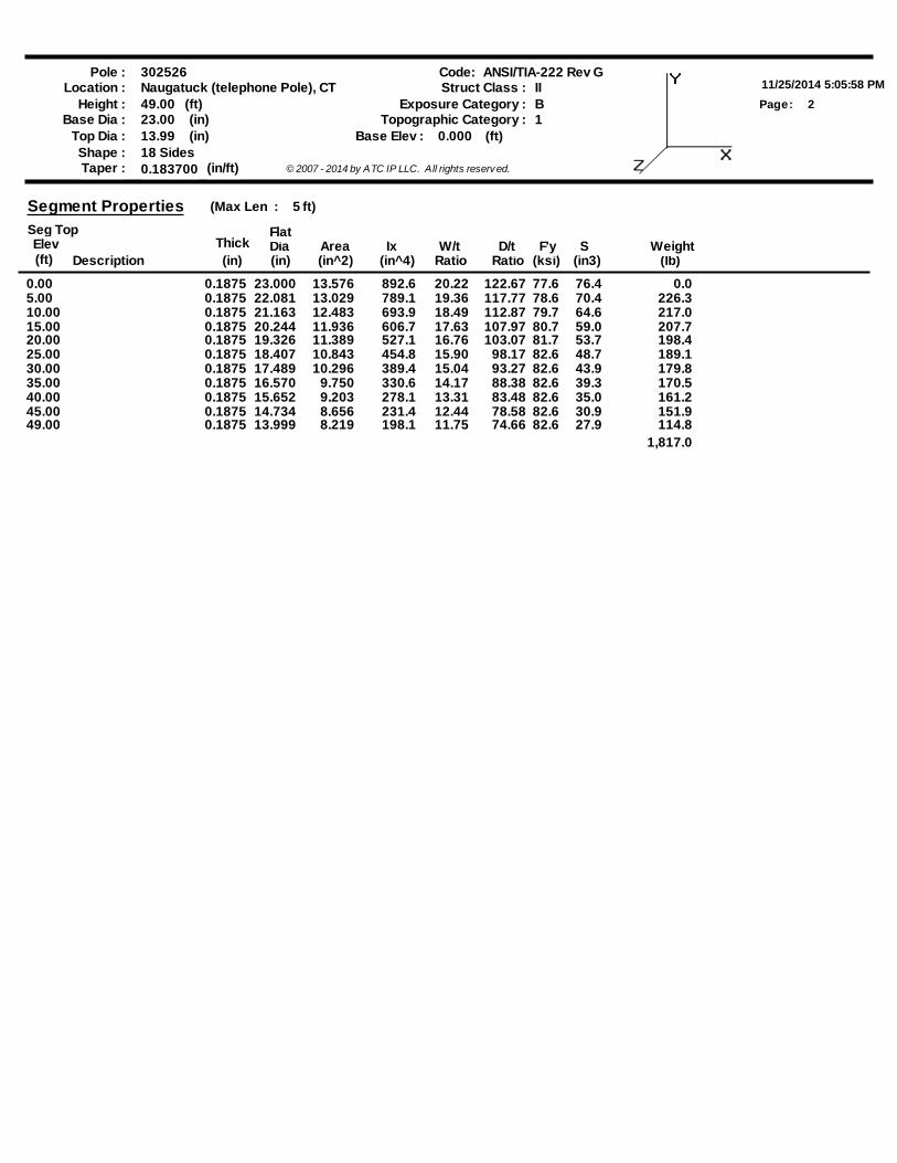
Segment Properties (Max Len : 5 ft)
Seg TopElev(ft) (ksi) (in3)
D/t F'y SFlat
0.00 0.1875 23.000 122.6720.22892.613.576 0.077.6 76.45.00 0.1875 22.081 117.7719.36789.113.029 226.378.6 70.410.00 0.1875 21.163 112.8718.49693.912.483 217.079.7 64.615.00 0.1875 20.244 107.9717.63606.711.936 207.780.7 59.020.00 0.1875 19.326 103.0716.76527.111.389 198.481.7 53.725.00 0.1875 18.407 98.1715.90454.810.843 189.182.6 48.730.00 0.1875 17.489 93.2715.04389.410.296 179.882.6 43.935.00 0.1875 16.570 88.3814.17330.69.750 170.582.6 39.340.00 0.1875 15.652 83.4813.31278.19.203 161.282.6 35.045.00 0.1875 14.734 78.5812.44231.48.656 151.982.6 30.949.00 0.1875 13.999 74.6611.75198.18.219 114.882.6 27.9
1,817.0
Pole :11/25/2014 5:05:58 PM
Code:
3Page:
302526Location : Naugatuck (telephone Pole), CT
Height : 49.00 (ft)
Shape : 18 Sides
(in)23.00Base Dia :Base Elev : 0.000 (ft)(in)13.99Top Dia :
Taper : 0.183700 (in/ft) © 2007 - 2014 by ATC IP LLC. All rights reserv ed.
ANSI/TIA-222 Rev GStruct Class : II
BExposure Category :1Topographic Category :
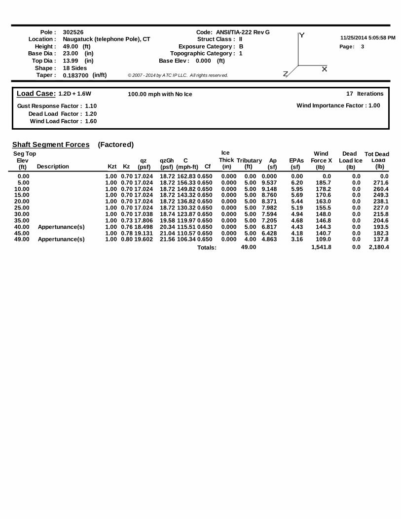
Load Case: 1.2D + 1.6W
Gust Response Factor : 1.10Dead Load Factor : 1.20Wind Load Factor : 1.60
17 Iterations
Wind Importance Factor : 1.00
100.00 mph with No Ice
DescriptionElev
Seg Top
(lb)Tributary
(ft)(mph-ft)(ft) Kzqz
(psf)C
CfAp(sf)
EPAs(sf) (lb)
WindLoad
(lb)
Shaft Segment Forces
Force XDead
Load IceqzGh(psf)
Tot Dead
Kzt
Ice
(in)Thick
(Factored)
0.00 1.00 0.70 17.024 18.72 162.83 0.650 0.000 0.00 0.000 0.00 0.0 0.0 0.0 5.00 1.00 0.70 17.024 18.72 156.33 0.650 0.000 5.00 9.537 6.20 185.7 0.0 271.6
10.00 1.00 0.70 17.024 18.72 149.82 0.650 0.000 5.00 9.148 5.95 178.2 0.0 260.4 15.00 1.00 0.70 17.024 18.72 143.32 0.650 0.000 5.00 8.760 5.69 170.6 0.0 249.3 20.00 1.00 0.70 17.024 18.72 136.82 0.650 0.000 5.00 8.371 5.44 163.0 0.0 238.1 25.00 1.00 0.70 17.024 18.72 130.32 0.650 0.000 5.00 7.982 5.19 155.5 0.0 227.0 30.00 1.00 0.70 17.038 18.74 123.87 0.650 0.000 5.00 7.594 4.94 148.0 0.0 215.8 35.00 1.00 0.73 17.806 19.58 119.97 0.650 0.000 5.00 7.205 4.68 146.8 0.0 204.6 40.00 Appertunance(s) 1.00 0.76 18.498 20.34 115.51 0.650 0.000 5.00 6.817 4.43 144.3 0.0 193.5 45.00 1.00 0.78 19.131 21.04 110.57 0.650 0.000 5.00 6.428 4.18 140.7 0.0 182.3 49.00 Appertunance(s) 1.00 0.80 19.602 21.56 106.34 0.650 0.000 4.00 4.863 3.16 109.0 0.0 137.8
Totals: 49.00 1,541.8 0.0 2,180.4
Pole :11/25/2014 5:05:58 PM
Code:
4Page:
302526Location : Naugatuck (telephone Pole), CT
Height : 49.00 (ft)
Shape : 18 Sides
(in)23.00Base Dia :Base Elev : 0.000 (ft)(in)13.99Top Dia :
Taper : 0.183700 (in/ft) © 2007 - 2014 by ATC IP LLC. All rights reserv ed.
ANSI/TIA-222 Rev GStruct Class : II
BExposure Category :1Topographic Category :
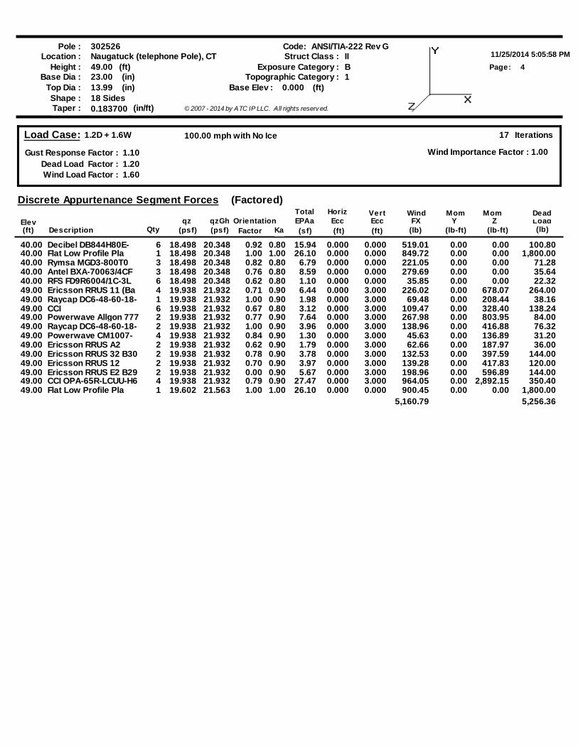
Load Case: 1.2D + 1.6W
Gust Response Factor : 1.10Dead Load Factor : 1.20Wind Load Factor : 1.60
17 Iterations
Wind Importance Factor : 1.00
100.00 mph with No Ice
(psf)
Discrete Appurtenance Segment Forces
Elev(ft) Description (sf)
EPAaFactor (ft)
VertEcc(ft)
WindFX
(lb)Load(lb)
qz(psf) (lb-ft)
Mom
(lb-ft)Y
MomZOrientation
HorizEcc
Qty
TotalqzGh
(Factored)Dead
Ka
40.00 Decibel DB844H80E- 6 18.498 20.348 0.92 15.94 0.000 0.000 519.01 0.00 0.00 100.800.8040.00 Flat Low Profile Pla 1 18.498 20.348 1.00 26.10 0.000 0.000 849.72 0.00 0.00 1,800.001.0040.00 Rymsa MGD3-800T0 3 18.498 20.348 0.82 6.79 0.000 0.000 221.05 0.00 0.00 71.280.8040.00 Antel BXA-70063/4CF 3 18.498 20.348 0.76 8.59 0.000 0.000 279.69 0.00 0.00 35.640.8040.00 RFS FD9R6004/1C-3L 6 18.498 20.348 0.62 1.10 0.000 0.000 35.85 0.00 0.00 22.320.8049.00 Ericsson RRUS 11 (Ba 4 19.938 21.932 0.71 6.44 0.000 3.000 226.02 0.00 678.07 264.000.9049.00 Raycap DC6-48-60-18- 1 19.938 21.932 1.00 1.98 0.000 3.000 69.48 0.00 208.44 38.160.9049.00 CCI 6 19.938 21.932 0.67 3.12 0.000 3.000 109.47 0.00 328.40 138.240.8049.00 Powerwave Allgon 777 2 19.938 21.932 0.77 7.64 0.000 3.000 267.98 0.00 803.95 84.000.9049.00 Raycap DC6-48-60-18- 2 19.938 21.932 1.00 3.96 0.000 3.000 138.96 0.00 416.88 76.320.9049.00 Powerwave CM1007- 4 19.938 21.932 0.84 1.30 0.000 3.000 45.63 0.00 136.89 31.200.9049.00 Ericsson RRUS A2 2 19.938 21.932 0.62 1.79 0.000 3.000 62.66 0.00 187.97 36.000.9049.00 Ericsson RRUS 32 B30 2 19.938 21.932 0.78 3.78 0.000 3.000 132.53 0.00 397.59 144.000.9049.00 Ericsson RRUS 12 2 19.938 21.932 0.70 3.97 0.000 3.000 139.28 0.00 417.83 120.000.9049.00 Ericsson RRUS E2 B29 2 19.938 21.932 0.00 5.67 0.000 3.000 198.96 0.00 596.89 144.000.9049.00 CCI OPA-65R-LCUU-H6 4 19.938 21.932 0.79 27.47 0.000 3.000 964.05 0.00 2,892.15 350.400.9049.00 Flat Low Profile Pla 1 19.602 21.563 1.00 26.10 0.000 0.000 900.45 0.00 0.00 1,800.001.00
5,160.79 5,256.36
Pole :11/25/2014 5:05:58 PM
Code:
5Page:
302526Location : Naugatuck (telephone Pole), CT
Height : 49.00 (ft)
Shape : 18 Sides
(in)23.00Base Dia :Base Elev : 0.000 (ft)(in)13.99Top Dia :
Taper : 0.183700 (in/ft) © 2007 - 2014 by ATC IP LLC. All rights reserv ed.
ANSI/TIA-222 Rev GStruct Class : II
BExposure Category :1Topographic Category :
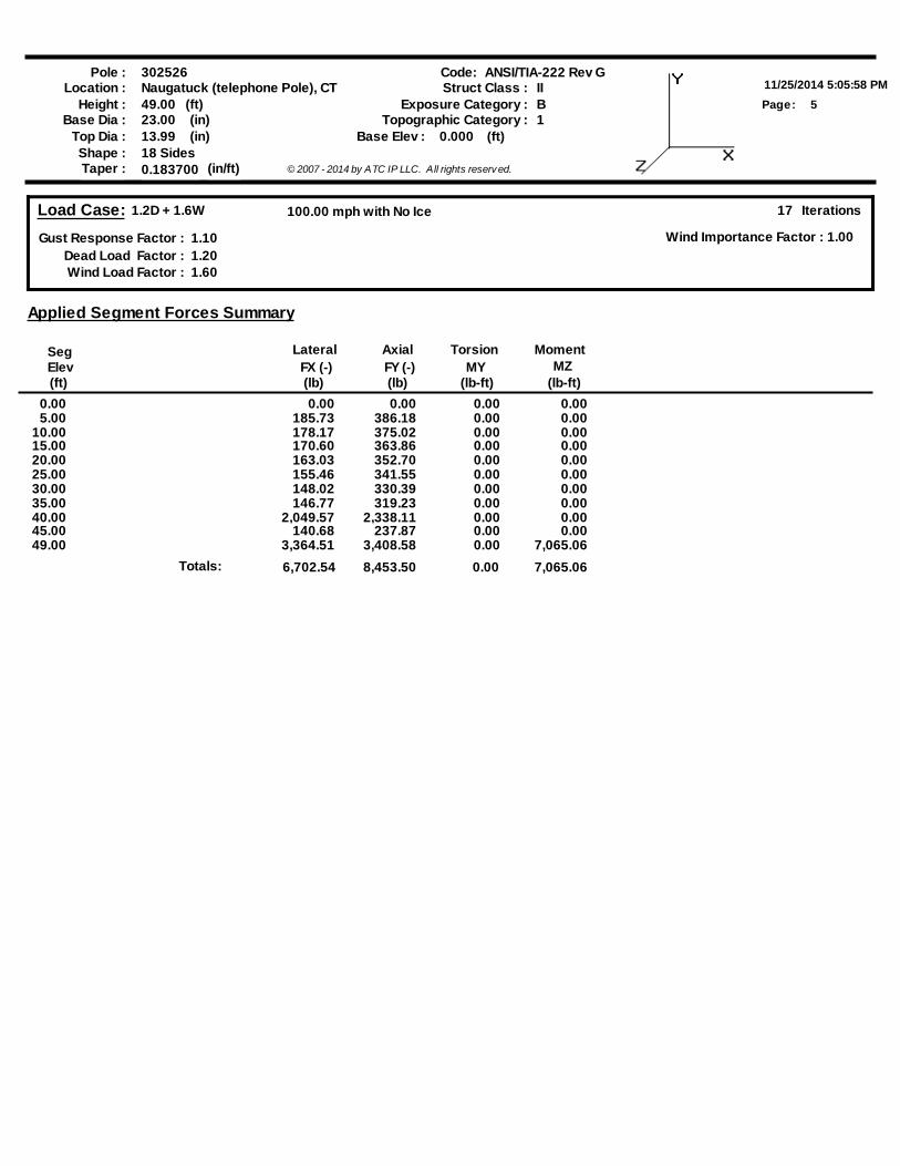
Load Case: 1.2D + 1.6W
Gust Response Factor : 1.10Dead Load Factor : 1.20Wind Load Factor : 1.60
17 Iterations
Wind Importance Factor : 1.00
100.00 mph with No Ice
SegElev(ft)
FX (-)(lb) (lb)
FY (-) MY(lb-ft) (lb-ft)
MZ
Applied Segment Forces Summary
Lateral Axial MomentTorsion
0.00 0.00 0.00 0.00 0.005.00 185.73 386.18 0.00 0.00
10.00 178.17 375.02 0.00 0.0015.00 170.60 363.86 0.00 0.0020.00 163.03 352.70 0.00 0.0025.00 155.46 341.55 0.00 0.0030.00 148.02 330.39 0.00 0.0035.00 146.77 319.23 0.00 0.0040.00 2,049.57 2,338.11 0.00 0.0045.00 140.68 237.87 0.00 0.0049.00 3,364.51 3,408.58 0.00 7,065.06
Totals: 6,702.54 8,453.50 0.00 7,065.06

Pole :11/25/2014 5:05:58 PM
Code:
6Page:
302526Location : Naugatuck (telephone Pole), CT
Height : 49.00 (ft)
Shape : 18 Sides
(in)23.00Base Dia :Base Elev : 0.000 (ft)(in)13.99Top Dia :
Taper : 0.183700 (in/ft) © 2007 - 2014 by ATC IP LLC. All rights reserv ed.
ANSI/TIA-222 Rev GStruct Class : II
BExposure Category :1Topographic Category :
Load Case: 1.2D + 1.6W
Gust Response Factor : 1.10Dead Load Factor : 1.20Wind Load Factor : 1.60
17 Iterations
Wind Importance Factor : 1.00
100.00 mph with No Ice
Calculated Forces
SegElev(ft)
Pn(kips)
Vn(kips)
Tn(ft-kips)
Mn(ft-kips)
PuFY (-)(kips)
VuFX (-)(kips)
MuMX
(ft-kips)MY
(ft-kips) (ft-kips)MZ
Tu Mu
RatioDeflect
(in)
TotalRotation
(deg)(ft-kips)MomentResultant phi phi phi phi
0.00 -8.43 -6.74 -291.580.00 0.00 291.58 948.37 474.19 444.99888.66 0.00 0.00 0.6645.00 -7.99 -6.61 -257.910.00 0.00 257.91 922.10 461.05 415.10828.97 0.24 -0.44 0.630
10.00 -7.57 -6.48 -224.860.00 0.00 224.86 894.83 447.42 385.78770.42 0.93 -0.87 0.59215.00 -7.16 -6.36 -192.440.00 0.00 192.44 866.56 433.28 357.09713.12 2.08 -1.30 0.54720.00 -6.77 -6.24 -160.640.00 0.00 160.64 837.29 418.65 329.08657.19 3.66 -1.71 0.49625.00 -6.39 -6.11 -129.470.00 0.00 129.47 805.56 402.78 301.27601.65 5.67 -2.11 0.43830.00 -6.04 -5.98 -98.920.00 0.00 98.92 764.96 382.48 271.51542.22 8.08 -2.46 0.37235.00 -5.70 -5.85 -69.000.00 0.00 69.00 724.35 362.17 243.30485.89 10.83 -2.77 0.29240.00 -3.45 -3.70 -39.750.00 0.00 39.75 683.74 341.87 216.64432.64 13.86 -3.00 0.18945.00 -3.22 -3.55 -21.260.00 0.00 21.26 643.13 321.56 191.53382.49 17.10 -3.16 0.11649.00 0.00 -3.36 -7.070.00 0.00 7.07 610.64 305.32 172.55344.59 19.78 -3.23 0.041
Pole :11/25/2014 5:05:58 PM
Code:
7Page:
302526Location : Naugatuck (telephone Pole), CT
Height : 49.00 (ft)
Shape : 18 Sides
(in)23.00Base Dia :Base Elev : 0.000 (ft)(in)13.99Top Dia :
Taper : 0.183700 (in/ft) © 2007 - 2014 by ATC IP LLC. All rights reserv ed.
ANSI/TIA-222 Rev GStruct Class : II
BExposure Category :1Topographic Category :
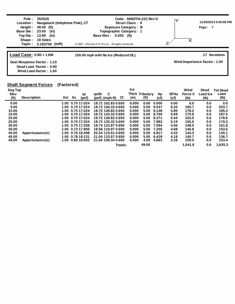
Load Case: 0.9D + 1.6W
Gust Response Factor : 1.10Dead Load Factor : 0.90Wind Load Factor : 1.60
17 Iterations
Wind Importance Factor : 1.00
100.00 mph with No Ice (Reduced DL)
DescriptionElev
Seg Top
(lb)Tributary
(ft)(mph-ft)(ft) Kzqz
(psf)C
CfAp(sf)
EPAs(sf) (lb)
WindLoad
(lb)
Shaft Segment Forces
Force XDead
Load IceqzGh(psf)
Tot Dead
Kzt
Ice
(in)Thick
(Factored)
0.00 1.00 0.70 17.024 18.72 162.83 0.650 0.000 0.00 0.000 0.00 0.0 0.0 0.0 5.00 1.00 0.70 17.024 18.72 156.33 0.650 0.000 5.00 9.537 6.20 185.7 0.0 203.7
10.00 1.00 0.70 17.024 18.72 149.82 0.650 0.000 5.00 9.148 5.95 178.2 0.0 195.3 15.00 1.00 0.70 17.024 18.72 143.32 0.650 0.000 5.00 8.760 5.69 170.6 0.0 187.0 20.00 1.00 0.70 17.024 18.72 136.82 0.650 0.000 5.00 8.371 5.44 163.0 0.0 178.6 25.00 1.00 0.70 17.024 18.72 130.32 0.650 0.000 5.00 7.982 5.19 155.5 0.0 170.2 30.00 1.00 0.70 17.038 18.74 123.87 0.650 0.000 5.00 7.594 4.94 148.0 0.0 161.8 35.00 1.00 0.73 17.806 19.58 119.97 0.650 0.000 5.00 7.205 4.68 146.8 0.0 153.5 40.00 Appertunance(s) 1.00 0.76 18.498 20.34 115.51 0.650 0.000 5.00 6.817 4.43 144.3 0.0 145.1 45.00 1.00 0.78 19.131 21.04 110.57 0.650 0.000 5.00 6.428 4.18 140.7 0.0 136.7 49.00 Appertunance(s) 1.00 0.80 19.602 21.56 106.34 0.650 0.000 4.00 4.863 3.16 109.0 0.0 103.4
Totals: 49.00 1,541.8 0.0 1,635.3
Pole :11/25/2014 5:05:58 PM
Code:
8Page:
302526Location : Naugatuck (telephone Pole), CT
Height : 49.00 (ft)
Shape : 18 Sides
(in)23.00Base Dia :Base Elev : 0.000 (ft)(in)13.99Top Dia :
Taper : 0.183700 (in/ft) © 2007 - 2014 by ATC IP LLC. All rights reserv ed.
ANSI/TIA-222 Rev GStruct Class : II
BExposure Category :1Topographic Category :
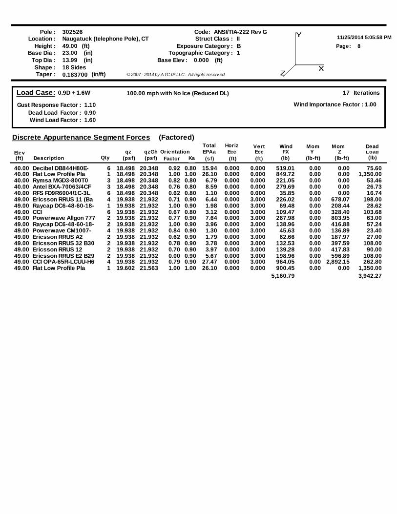
Load Case: 0.9D + 1.6W
Gust Response Factor : 1.10Dead Load Factor : 0.90Wind Load Factor : 1.60
17 Iterations
Wind Importance Factor : 1.00
100.00 mph with No Ice (Reduced DL)
(psf)
Discrete Appurtenance Segment Forces
Elev(ft) Description (sf)
EPAaFactor (ft)
VertEcc(ft)
WindFX
(lb)Load(lb)
qz(psf) (lb-ft)
Mom
(lb-ft)Y
MomZOrientation
HorizEcc
Qty
TotalqzGh
(Factored)Dead
Ka
40.00 Decibel DB844H80E- 6 18.498 20.348 0.92 15.94 0.000 0.000 519.01 0.00 0.00 75.600.8040.00 Flat Low Profile Pla 1 18.498 20.348 1.00 26.10 0.000 0.000 849.72 0.00 0.00 1,350.001.0040.00 Rymsa MGD3-800T0 3 18.498 20.348 0.82 6.79 0.000 0.000 221.05 0.00 0.00 53.460.8040.00 Antel BXA-70063/4CF 3 18.498 20.348 0.76 8.59 0.000 0.000 279.69 0.00 0.00 26.730.8040.00 RFS FD9R6004/1C-3L 6 18.498 20.348 0.62 1.10 0.000 0.000 35.85 0.00 0.00 16.740.8049.00 Ericsson RRUS 11 (Ba 4 19.938 21.932 0.71 6.44 0.000 3.000 226.02 0.00 678.07 198.000.9049.00 Raycap DC6-48-60-18- 1 19.938 21.932 1.00 1.98 0.000 3.000 69.48 0.00 208.44 28.620.9049.00 CCI 6 19.938 21.932 0.67 3.12 0.000 3.000 109.47 0.00 328.40 103.680.8049.00 Powerwave Allgon 777 2 19.938 21.932 0.77 7.64 0.000 3.000 267.98 0.00 803.95 63.000.9049.00 Raycap DC6-48-60-18- 2 19.938 21.932 1.00 3.96 0.000 3.000 138.96 0.00 416.88 57.240.9049.00 Powerwave CM1007- 4 19.938 21.932 0.84 1.30 0.000 3.000 45.63 0.00 136.89 23.400.9049.00 Ericsson RRUS A2 2 19.938 21.932 0.62 1.79 0.000 3.000 62.66 0.00 187.97 27.000.9049.00 Ericsson RRUS 32 B30 2 19.938 21.932 0.78 3.78 0.000 3.000 132.53 0.00 397.59 108.000.9049.00 Ericsson RRUS 12 2 19.938 21.932 0.70 3.97 0.000 3.000 139.28 0.00 417.83 90.000.9049.00 Ericsson RRUS E2 B29 2 19.938 21.932 0.00 5.67 0.000 3.000 198.96 0.00 596.89 108.000.9049.00 CCI OPA-65R-LCUU-H6 4 19.938 21.932 0.79 27.47 0.000 3.000 964.05 0.00 2,892.15 262.800.9049.00 Flat Low Profile Pla 1 19.602 21.563 1.00 26.10 0.000 0.000 900.45 0.00 0.00 1,350.001.00
5,160.79 3,942.27

Pole :11/25/2014 5:05:58 PM
Code:
9Page:
302526Location : Naugatuck (telephone Pole), CT
Height : 49.00 (ft)
Shape : 18 Sides
(in)23.00Base Dia :Base Elev : 0.000 (ft)(in)13.99Top Dia :
Taper : 0.183700 (in/ft) © 2007 - 2014 by ATC IP LLC. All rights reserv ed.
ANSI/TIA-222 Rev GStruct Class : II
BExposure Category :1Topographic Category :
Load Case: 0.9D + 1.6W
Gust Response Factor : 1.10Dead Load Factor : 0.90Wind Load Factor : 1.60
17 Iterations
Wind Importance Factor : 1.00
100.00 mph with No Ice (Reduced DL)
SegElev(ft)
FX (-)(lb) (lb)
FY (-) MY(lb-ft) (lb-ft)
MZ
Applied Segment Forces Summary
Lateral Axial MomentTorsion
0.00 0.00 0.00 0.00 0.005.00 185.73 289.64 0.00 0.00
10.00 178.17 281.27 0.00 0.0015.00 170.60 272.90 0.00 0.0020.00 163.03 264.53 0.00 0.0025.00 155.46 256.16 0.00 0.0030.00 148.02 247.79 0.00 0.0035.00 146.77 239.42 0.00 0.0040.00 2,049.57 1,753.58 0.00 0.0045.00 140.68 178.40 0.00 0.0049.00 3,364.51 2,556.44 0.00 7,065.06
Totals: 6,702.54 6,340.12 0.00 7,065.06
Pole :11/25/2014 5:05:58 PM
Code:
10Page:
302526Location : Naugatuck (telephone Pole), CT
Height : 49.00 (ft)
Shape : 18 Sides
(in)23.00Base Dia :Base Elev : 0.000 (ft)(in)13.99Top Dia :
Taper : 0.183700 (in/ft) © 2007 - 2014 by ATC IP LLC. All rights reserv ed.
ANSI/TIA-222 Rev GStruct Class : II
BExposure Category :1Topographic Category :
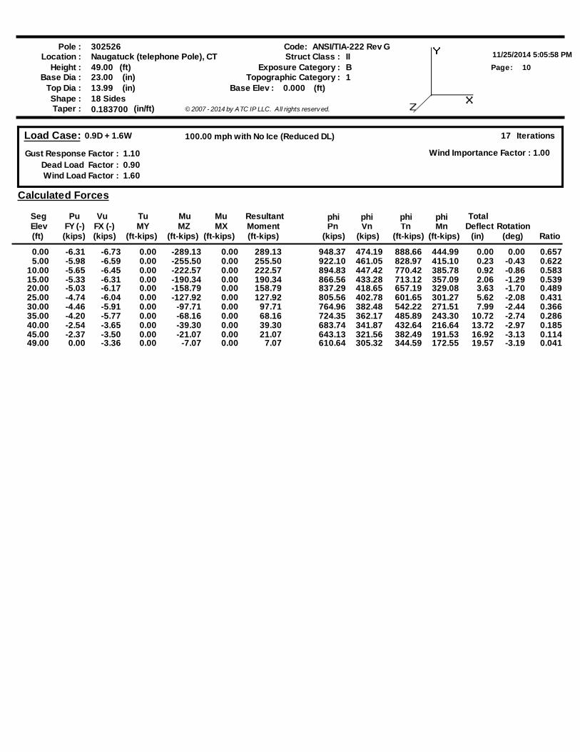
Load Case: 0.9D + 1.6W
Gust Response Factor : 1.10Dead Load Factor : 0.90Wind Load Factor : 1.60
17 Iterations
Wind Importance Factor : 1.00
100.00 mph with No Ice (Reduced DL)
Calculated Forces
SegElev(ft)
Pn(kips)
Vn(kips)
Tn(ft-kips)
Mn(ft-kips)
PuFY (-)(kips)
VuFX (-)(kips)
MuMX
(ft-kips)MY
(ft-kips) (ft-kips)MZ
Tu Mu
RatioDeflect
(in)
TotalRotation
(deg)(ft-kips)MomentResultant phi phi phi phi
0.00 -6.31 -6.73 -289.130.00 0.00 289.13 948.37 474.19 444.99888.66 0.00 0.00 0.6575.00 -5.98 -6.59 -255.500.00 0.00 255.50 922.10 461.05 415.10828.97 0.23 -0.43 0.622
10.00 -5.65 -6.45 -222.570.00 0.00 222.57 894.83 447.42 385.78770.42 0.92 -0.86 0.58315.00 -5.33 -6.31 -190.340.00 0.00 190.34 866.56 433.28 357.09713.12 2.06 -1.29 0.53920.00 -5.03 -6.17 -158.790.00 0.00 158.79 837.29 418.65 329.08657.19 3.63 -1.70 0.48925.00 -4.74 -6.04 -127.920.00 0.00 127.92 805.56 402.78 301.27601.65 5.62 -2.08 0.43130.00 -4.46 -5.91 -97.710.00 0.00 97.71 764.96 382.48 271.51542.22 7.99 -2.44 0.36635.00 -4.20 -5.77 -68.160.00 0.00 68.16 724.35 362.17 243.30485.89 10.72 -2.74 0.28640.00 -2.54 -3.65 -39.300.00 0.00 39.30 683.74 341.87 216.64432.64 13.72 -2.97 0.18545.00 -2.37 -3.50 -21.070.00 0.00 21.07 643.13 321.56 191.53382.49 16.92 -3.13 0.11449.00 0.00 -3.36 -7.070.00 0.00 7.07 610.64 305.32 172.55344.59 19.57 -3.19 0.041
Pole :11/25/2014 5:05:58 PM
Code:
11Page:
302526Location : Naugatuck (telephone Pole), CT
Height : 49.00 (ft)
Shape : 18 Sides
(in)23.00Base Dia :Base Elev : 0.000 (ft)(in)13.99Top Dia :
Taper : 0.183700 (in/ft) © 2007 - 2014 by ATC IP LLC. All rights reserv ed.
ANSI/TIA-222 Rev GStruct Class : II
BExposure Category :1Topographic Category :
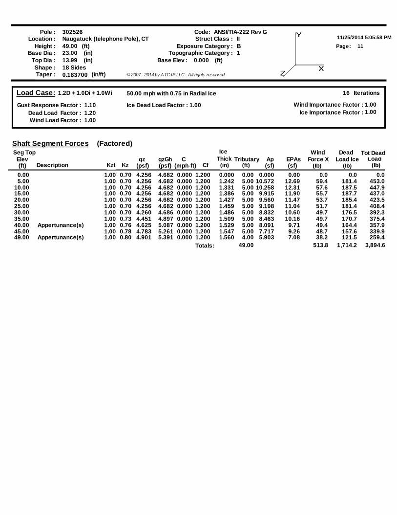
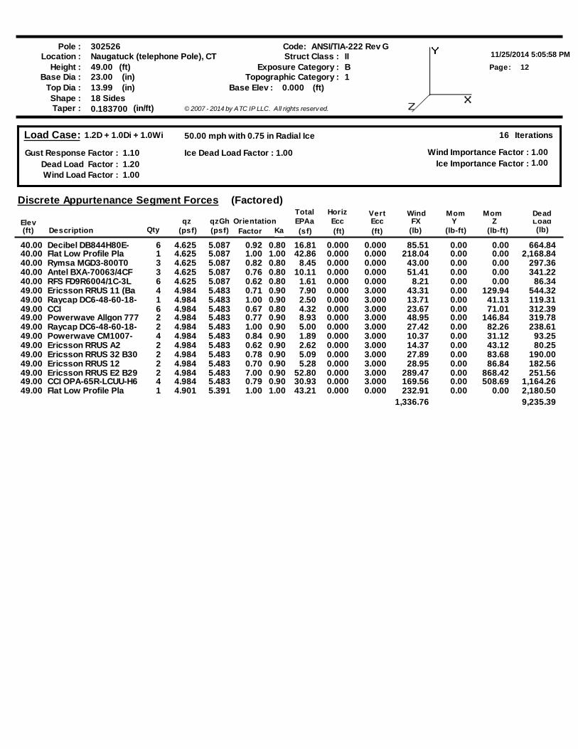
Load Case: 1.2D + 1.0Di + 1.0Wi
Gust Response Factor : 1.10Dead Load Factor : 1.20Wind Load Factor : 1.00
16 Iterations
Wind Importance Factor :Ice Importance Factor :
1.001.00
Ice Dead Load Factor : 1.00
50.00 mph with 0.75 in Radial Ice
DescriptionElev
Seg Top
(lb)Tributary
(ft)(mph-ft)(ft) Kzqz
(psf)C
CfAp(sf)
EPAs(sf) (lb)
WindLoad
(lb)
Shaft Segment Forces
Force XDead
Load IceqzGh(psf)
Tot Dead
Kzt
Ice
(in)Thick
(Factored)
0.00 1.00 0.70 4.256 4.682 0.000 1.200 0.000 0.00 0.000 0.00 0.0 0.0 0.0 5.00 1.00 0.70 4.256 4.682 0.000 1.200 1.242 5.00 10.572 12.69 59.4 181.4 453.0
10.00 1.00 0.70 4.256 4.682 0.000 1.200 1.331 5.00 10.258 12.31 57.6 187.5 447.9 15.00 1.00 0.70 4.256 4.682 0.000 1.200 1.386 5.00 9.915 11.90 55.7 187.7 437.0 20.00 1.00 0.70 4.256 4.682 0.000 1.200 1.427 5.00 9.560 11.47 53.7 185.4 423.5 25.00 1.00 0.70 4.256 4.682 0.000 1.200 1.459 5.00 9.198 11.04 51.7 181.4 408.4 30.00 1.00 0.70 4.260 4.686 0.000 1.200 1.486 5.00 8.832 10.60 49.7 176.5 392.3 35.00 1.00 0.73 4.451 4.897 0.000 1.200 1.509 5.00 8.463 10.16 49.7 170.7 375.4 40.00 Appertunance(s) 1.00 0.76 4.625 5.087 0.000 1.200 1.529 5.00 8.091 9.71 49.4 164.4 357.9 45.00 1.00 0.78 4.783 5.261 0.000 1.200 1.547 5.00 7.717 9.26 48.7 157.6 339.9 49.00 Appertunance(s) 1.00 0.80 4.901 5.391 0.000 1.200 1.560 4.00 5.903 7.08 38.2 121.5 259.4
Totals: 49.00 513.8 1,714.2 3,894.6
Pole :11/25/2014 5:05:58 PM
Code:
12Page:
302526Location : Naugatuck (telephone Pole), CT
Height : 49.00 (ft)
Shape : 18 Sides
(in)23.00Base Dia :Base Elev : 0.000 (ft)(in)13.99Top Dia :
Taper : 0.183700 (in/ft) © 2007 - 2014 by ATC IP LLC. All rights reserv ed.
ANSI/TIA-222 Rev GStruct Class : II
BExposure Category :1Topographic Category :
Load Case: 1.2D + 1.0Di + 1.0Wi
Gust Response Factor : 1.10Dead Load Factor : 1.20Wind Load Factor : 1.00
16 Iterations
Wind Importance Factor :Ice Importance Factor :
1.001.00
Ice Dead Load Factor : 1.00
50.00 mph with 0.75 in Radial Ice
(psf)
Discrete Appurtenance Segment Forces
Elev(ft) Description (sf)
EPAaFactor (ft)
VertEcc(ft)
WindFX
(lb)Load(lb)
qz(psf) (lb-ft)
Mom
(lb-ft)Y
MomZOrientation
HorizEcc
Qty
TotalqzGh
(Factored)Dead
Ka
40.00 Decibel DB844H80E- 6 4.625 5.087 0.92 16.81 0.000 0.000 85.51 0.00 0.00 664.840.8040.00 Flat Low Profile Pla 1 4.625 5.087 1.00 42.86 0.000 0.000 218.04 0.00 0.00 2,168.841.0040.00 Rymsa MGD3-800T0 3 4.625 5.087 0.82 8.45 0.000 0.000 43.00 0.00 0.00 297.360.8040.00 Antel BXA-70063/4CF 3 4.625 5.087 0.76 10.11 0.000 0.000 51.41 0.00 0.00 341.220.8040.00 RFS FD9R6004/1C-3L 6 4.625 5.087 0.62 1.61 0.000 0.000 8.21 0.00 0.00 86.340.8049.00 Ericsson RRUS 11 (Ba 4 4.984 5.483 0.71 7.90 0.000 3.000 43.31 0.00 129.94 544.320.9049.00 Raycap DC6-48-60-18- 1 4.984 5.483 1.00 2.50 0.000 3.000 13.71 0.00 41.13 119.310.9049.00 CCI 6 4.984 5.483 0.67 4.32 0.000 3.000 23.67 0.00 71.01 312.390.8049.00 Powerwave Allgon 777 2 4.984 5.483 0.77 8.93 0.000 3.000 48.95 0.00 146.84 319.780.9049.00 Raycap DC6-48-60-18- 2 4.984 5.483 1.00 5.00 0.000 3.000 27.42 0.00 82.26 238.610.9049.00 Powerwave CM1007- 4 4.984 5.483 0.84 1.89 0.000 3.000 10.37 0.00 31.12 93.250.9049.00 Ericsson RRUS A2 2 4.984 5.483 0.62 2.62 0.000 3.000 14.37 0.00 43.12 80.250.9049.00 Ericsson RRUS 32 B30 2 4.984 5.483 0.78 5.09 0.000 3.000 27.89 0.00 83.68 190.000.9049.00 Ericsson RRUS 12 2 4.984 5.483 0.70 5.28 0.000 3.000 28.95 0.00 86.84 182.560.9049.00 Ericsson RRUS E2 B29 2 4.984 5.483 7.00 52.80 0.000 3.000 289.47 0.00 868.42 251.560.9049.00 CCI OPA-65R-LCUU-H6 4 4.984 5.483 0.79 30.93 0.000 3.000 169.56 0.00 508.69 1,164.260.9049.00 Flat Low Profile Pla 1 4.901 5.391 1.00 43.21 0.000 0.000 232.91 0.00 0.00 2,180.501.00
1,336.76 9,235.39
Pole :11/25/2014 5:05:58 PM
Code:
13Page:
302526Location : Naugatuck (telephone Pole), CT
Height : 49.00 (ft)
Shape : 18 Sides
(in)23.00Base Dia :Base Elev : 0.000 (ft)(in)13.99Top Dia :
Taper : 0.183700 (in/ft) © 2007 - 2014 by ATC IP LLC. All rights reserv ed.
ANSI/TIA-222 Rev GStruct Class : II
BExposure Category :1Topographic Category :
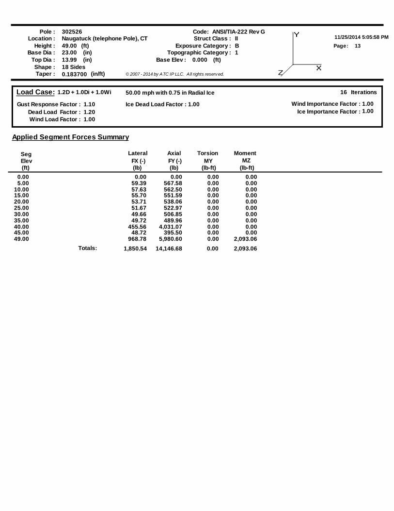
Load Case: 1.2D + 1.0Di + 1.0Wi
Gust Response Factor : 1.10Dead Load Factor : 1.20Wind Load Factor : 1.00
16 Iterations
Wind Importance Factor :Ice Importance Factor :
1.001.00
Ice Dead Load Factor : 1.00
50.00 mph with 0.75 in Radial Ice
SegElev(ft)
FX (-)(lb) (lb)
FY (-) MY(lb-ft) (lb-ft)
MZ
Applied Segment Forces Summary
Lateral Axial MomentTorsion
0.00 0.00 0.00 0.00 0.005.00 59.39 567.58 0.00 0.00
10.00 57.63 562.50 0.00 0.0015.00 55.70 551.59 0.00 0.0020.00 53.71 538.06 0.00 0.0025.00 51.67 522.97 0.00 0.0030.00 49.66 506.85 0.00 0.0035.00 49.72 489.96 0.00 0.0040.00 455.56 4,031.07 0.00 0.0045.00 48.72 395.50 0.00 0.0049.00 968.78 5,980.60 0.00 2,093.06
Totals: 1,850.54 14,146.68 0.00 2,093.06

Pole :11/25/2014 5:05:58 PM
Code:
14Page:
302526Location : Naugatuck (telephone Pole), CT
Height : 49.00 (ft)
Shape : 18 Sides
(in)23.00Base Dia :Base Elev : 0.000 (ft)(in)13.99Top Dia :
Taper : 0.183700 (in/ft) © 2007 - 2014 by ATC IP LLC. All rights reserv ed.
ANSI/TIA-222 Rev GStruct Class : II
BExposure Category :1Topographic Category :
Load Case: 1.2D + 1.0Di + 1.0Wi
Gust Response Factor : 1.10Dead Load Factor : 1.20Wind Load Factor : 1.00
16 Iterations
Wind Importance Factor :Ice Importance Factor :
1.001.00
Ice Dead Load Factor : 1.00
50.00 mph with 0.75 in Radial Ice
Calculated Forces
SegElev(ft)
Pn(kips)
Vn(kips)
Tn(ft-kips)
Mn(ft-kips)
PuFY (-)(kips)
VuFX (-)(kips)
MuMX
(ft-kips)MY
(ft-kips) (ft-kips)MZ
Tu Mu
RatioDeflect
(in)
TotalRotation
(deg)(ft-kips)MomentResultant phi phi phi phi
0.00 -14.14 -1.87 -81.910.00 0.00 81.91 948.37 474.19 444.99888.66 0.00 0.00 0.1995.00 -13.57 -1.83 -72.580.00 0.00 72.58 922.10 461.05 415.10828.97 0.07 -0.12 0.190
10.00 -13.01 -1.80 -63.410.00 0.00 63.41 894.83 447.42 385.78770.42 0.26 -0.25 0.17915.00 -12.45 -1.77 -54.390.00 0.00 54.39 866.56 433.28 357.09713.12 0.58 -0.37 0.16720.00 -11.91 -1.74 -45.540.00 0.00 45.54 837.29 418.65 329.08657.19 1.03 -0.48 0.15325.00 -11.39 -1.70 -36.860.00 0.00 36.86 805.56 402.78 301.27601.65 1.60 -0.59 0.13630.00 -10.88 -1.66 -28.350.00 0.00 28.35 764.96 382.48 271.51542.22 2.28 -0.70 0.11935.00 -10.38 -1.62 -20.030.00 0.00 20.03 724.35 362.17 243.30485.89 3.06 -0.79 0.09740.00 -6.36 -1.12 -11.920.00 0.00 11.92 683.74 341.87 216.64432.64 3.92 -0.85 0.06445.00 -5.96 -1.06 -6.350.00 0.00 6.35 643.13 321.56 191.53382.49 4.84 -0.90 0.04249.00 0.00 -0.97 -2.090.00 0.00 2.09 610.64 305.32 172.55344.59 5.61 -0.92 0.012
Pole :11/25/2014 5:05:58 PM
Code:
15Page:
302526Location : Naugatuck (telephone Pole), CT
Height : 49.00 (ft)
Shape : 18 Sides
(in)23.00Base Dia :Base Elev : 0.000 (ft)(in)13.99Top Dia :
Taper : 0.183700 (in/ft) © 2007 - 2014 by ATC IP LLC. All rights reserv ed.
ANSI/TIA-222 Rev GStruct Class : II
BExposure Category :1Topographic Category :
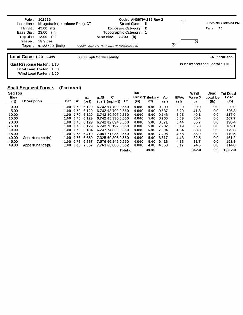
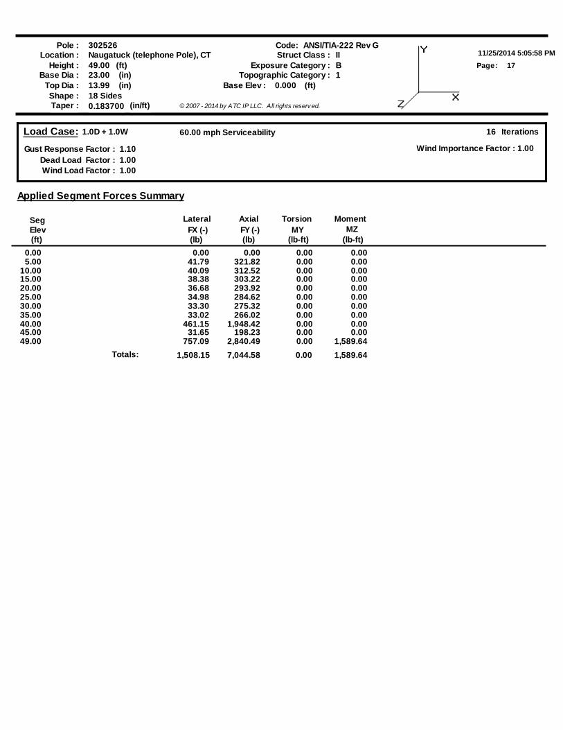
Load Case: 1.0D + 1.0W
Gust Response Factor : 1.10Dead Load Factor : 1.00Wind Load Factor : 1.00
16 Iterations
Wind Importance Factor : 1.00
60.00 mph Serviceability
DescriptionElev
Seg Top
(lb)Tributary
(ft)(mph-ft)(ft) Kzqz
(psf)C
CfAp(sf)
EPAs(sf) (lb)
WindLoad
(lb)
Shaft Segment Forces
Force XDead
Load IceqzGh(psf)
Tot Dead
Kzt
Ice
(in)Thick
(Factored)
0.00 1.00 0.70 6.129 6.742 97.700 0.650 0.000 0.00 0.000 0.00 0.0 0.0 0.0 5.00 1.00 0.70 6.129 6.742 93.799 0.650 0.000 5.00 9.537 6.20 41.8 0.0 226.3
10.00 1.00 0.70 6.129 6.742 89.897 0.650 0.000 5.00 9.148 5.95 40.1 0.0 217.0 15.00 1.00 0.70 6.129 6.742 85.995 0.650 0.000 5.00 8.760 5.69 38.4 0.0 207.7 20.00 1.00 0.70 6.129 6.742 82.094 0.650 0.000 5.00 8.371 5.44 36.7 0.0 198.4 25.00 1.00 0.70 6.129 6.742 78.192 0.650 0.000 5.00 7.982 5.19 35.0 0.0 189.1 30.00 1.00 0.70 6.134 6.747 74.322 0.650 0.000 5.00 7.594 4.94 33.3 0.0 179.8 35.00 1.00 0.73 6.410 7.051 71.986 0.650 0.000 5.00 7.205 4.68 33.0 0.0 170.5 40.00 Appertunance(s) 1.00 0.76 6.659 7.325 69.306 0.650 0.000 5.00 6.817 4.43 32.5 0.0 161.2 45.00 1.00 0.78 6.887 7.576 66.346 0.650 0.000 5.00 6.428 4.18 31.7 0.0 151.9 49.00 Appertunance(s) 1.00 0.80 7.057 7.763 63.808 0.652 0.000 4.00 4.863 3.17 24.6 0.0 114.8
Totals: 49.00 347.0 0.0 1,817.0
Pole :11/25/2014 5:05:58 PM
Code:
16Page:
302526Location : Naugatuck (telephone Pole), CT
Height : 49.00 (ft)
Shape : 18 Sides
(in)23.00Base Dia :Base Elev : 0.000 (ft)(in)13.99Top Dia :
Taper : 0.183700 (in/ft) © 2007 - 2014 by ATC IP LLC. All rights reserv ed.
ANSI/TIA-222 Rev GStruct Class : II
BExposure Category :1Topographic Category :
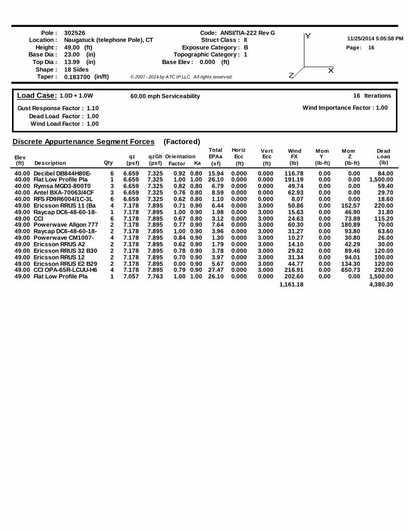
Load Case: 1.0D + 1.0W
Gust Response Factor : 1.10Dead Load Factor : 1.00Wind Load Factor : 1.00
16 Iterations
Wind Importance Factor : 1.00
60.00 mph Serviceability
(psf)
Discrete Appurtenance Segment Forces
Elev(ft) Description (sf)
EPAaFactor (ft)
VertEcc(ft)
WindFX
(lb)Load(lb)
qz(psf) (lb-ft)
Mom
(lb-ft)Y
MomZOrientation
HorizEcc
Qty
TotalqzGh
(Factored)Dead
Ka
40.00 Decibel DB844H80E- 6 6.659 7.325 0.92 15.94 0.000 0.000 116.78 0.00 0.00 84.000.8040.00 Flat Low Profile Pla 1 6.659 7.325 1.00 26.10 0.000 0.000 191.19 0.00 0.00 1,500.001.0040.00 Rymsa MGD3-800T0 3 6.659 7.325 0.82 6.79 0.000 0.000 49.74 0.00 0.00 59.400.8040.00 Antel BXA-70063/4CF 3 6.659 7.325 0.76 8.59 0.000 0.000 62.93 0.00 0.00 29.700.8040.00 RFS FD9R6004/1C-3L 6 6.659 7.325 0.62 1.10 0.000 0.000 8.07 0.00 0.00 18.600.8049.00 Ericsson RRUS 11 (Ba 4 7.178 7.895 0.71 6.44 0.000 3.000 50.86 0.00 152.57 220.000.9049.00 Raycap DC6-48-60-18- 1 7.178 7.895 1.00 1.98 0.000 3.000 15.63 0.00 46.90 31.800.9049.00 CCI 6 7.178 7.895 0.67 3.12 0.000 3.000 24.63 0.00 73.89 115.200.8049.00 Powerwave Allgon 777 2 7.178 7.895 0.77 7.64 0.000 3.000 60.30 0.00 180.89 70.000.9049.00 Raycap DC6-48-60-18- 2 7.178 7.895 1.00 3.96 0.000 3.000 31.27 0.00 93.80 63.600.9049.00 Powerwave CM1007- 4 7.178 7.895 0.84 1.30 0.000 3.000 10.27 0.00 30.80 26.000.9049.00 Ericsson RRUS A2 2 7.178 7.895 0.62 1.79 0.000 3.000 14.10 0.00 42.29 30.000.9049.00 Ericsson RRUS 32 B30 2 7.178 7.895 0.78 3.78 0.000 3.000 29.82 0.00 89.46 120.000.9049.00 Ericsson RRUS 12 2 7.178 7.895 0.70 3.97 0.000 3.000 31.34 0.00 94.01 100.000.9049.00 Ericsson RRUS E2 B29 2 7.178 7.895 0.00 5.67 0.000 3.000 44.77 0.00 134.30 120.000.9049.00 CCI OPA-65R-LCUU-H6 4 7.178 7.895 0.79 27.47 0.000 3.000 216.91 0.00 650.73 292.000.9049.00 Flat Low Profile Pla 1 7.057 7.763 1.00 26.10 0.000 0.000 202.60 0.00 0.00 1,500.001.00
1,161.18 4,380.30
Pole :11/25/2014 5:05:58 PM
Code:
17Page:
302526Location : Naugatuck (telephone Pole), CT
Height : 49.00 (ft)
Shape : 18 Sides
(in)23.00Base Dia :Base Elev : 0.000 (ft)(in)13.99Top Dia :
Taper : 0.183700 (in/ft) © 2007 - 2014 by ATC IP LLC. All rights reserv ed.
ANSI/TIA-222 Rev GStruct Class : II
BExposure Category :1Topographic Category :
Load Case: 1.0D + 1.0W
Gust Response Factor : 1.10Dead Load Factor : 1.00Wind Load Factor : 1.00
16 Iterations
Wind Importance Factor : 1.00
60.00 mph Serviceability
SegElev(ft)
FX (-)(lb) (lb)
FY (-) MY(lb-ft) (lb-ft)
MZ
Applied Segment Forces Summary
Lateral Axial MomentTorsion
0.00 0.00 0.00 0.00 0.005.00 41.79 321.82 0.00 0.00
10.00 40.09 312.52 0.00 0.0015.00 38.38 303.22 0.00 0.0020.00 36.68 293.92 0.00 0.0025.00 34.98 284.62 0.00 0.0030.00 33.30 275.32 0.00 0.0035.00 33.02 266.02 0.00 0.0040.00 461.15 1,948.42 0.00 0.0045.00 31.65 198.23 0.00 0.0049.00 757.09 2,840.49 0.00 1,589.64
Totals: 1,508.15 7,044.58 0.00 1,589.64
Pole :11/25/2014 5:05:58 PM
Code:
18Page:
302526Location : Naugatuck (telephone Pole), CT
Height : 49.00 (ft)
Shape : 18 Sides
(in)23.00Base Dia :Base Elev : 0.000 (ft)(in)13.99Top Dia :
Taper : 0.183700 (in/ft) © 2007 - 2014 by ATC IP LLC. All rights reserv ed.
ANSI/TIA-222 Rev GStruct Class : II
BExposure Category :1Topographic Category :
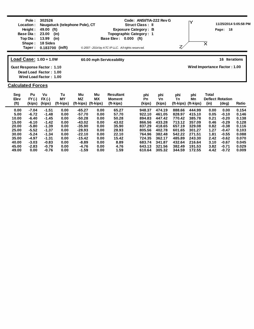
Load Case: 1.0D + 1.0W
Gust Response Factor : 1.10Dead Load Factor : 1.00Wind Load Factor : 1.00
16 Iterations
Wind Importance Factor : 1.00
60.00 mph Serviceability
Calculated Forces
SegElev(ft)
Pn(kips)
Vn(kips)
Tn(ft-kips)
Mn(ft-kips)
PuFY (-)(kips)
VuFX (-)(kips)
MuMX
(ft-kips)MY
(ft-kips) (ft-kips)MZ
Tu Mu
RatioDeflect
(in)
TotalRotation
(deg)(ft-kips)MomentResultant phi phi phi phi
0.00 -7.04 -1.51 -65.270.00 0.00 65.27 948.37 474.19 444.99888.66 0.00 0.00 0.1545.00 -6.72 -1.48 -57.700.00 0.00 57.70 922.10 461.05 415.10828.97 0.05 -0.10 0.146
10.00 -6.40 -1.45 -50.280.00 0.00 50.28 894.83 447.42 385.78770.42 0.21 -0.20 0.13815.00 -6.10 -1.42 -43.020.00 0.00 43.02 866.56 433.28 357.09713.12 0.46 -0.29 0.12820.00 -5.80 -1.39 -35.900.00 0.00 35.90 837.29 418.65 329.08657.19 0.82 -0.38 0.11625.00 -5.52 -1.37 -28.930.00 0.00 28.93 805.56 402.78 301.27601.65 1.27 -0.47 0.10330.00 -5.24 -1.34 -22.100.00 0.00 22.10 764.96 382.48 271.51542.22 1.81 -0.55 0.08835.00 -4.97 -1.31 -15.420.00 0.00 15.42 724.35 362.17 243.30485.89 2.42 -0.62 0.07040.00 -3.03 -0.83 -8.890.00 0.00 8.89 683.74 341.87 216.64432.64 3.10 -0.67 0.04545.00 -2.83 -0.79 -4.760.00 0.00 4.76 643.13 321.56 191.53382.49 3.82 -0.71 0.02949.00 0.00 -0.76 -1.590.00 0.00 1.59 610.64 305.32 172.55344.59 4.42 -0.72 0.009
Pole :11/25/2014 5:05:58 PM
Code:
19Page:
302526Location : Naugatuck (telephone Pole), CT
Height : 49.00 (ft)
Shape : 18 Sides
(in)23.00Base Dia :Base Elev : 0.000 (ft)(in)13.99Top Dia :
Taper : 0.183700 (in/ft) © 2007 - 2014 by ATC IP LLC. All rights reserv ed.
ANSI/TIA-222 Rev GStruct Class : II
BExposure Category :1Topographic Category :
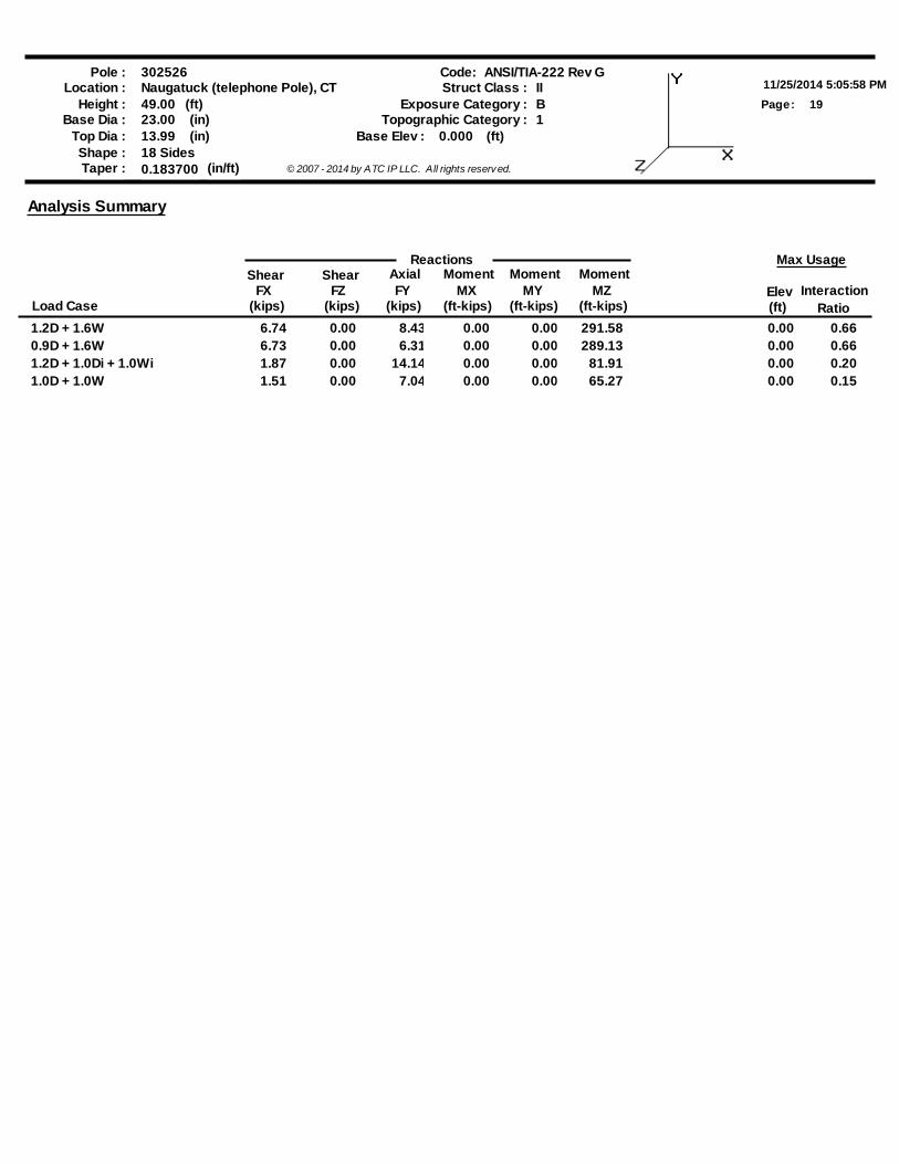
Analysis Summary
Load Case (kips)FZ
Shear Reactions
AxialFY
(kips) (ft-kips)MX
MomentElev(ft) Ratio
Interaction
Max UsageShear
FX(kips)
MomentMZ
(ft-kips)
MomentMY
(ft-kips)
1.2D + 1.6W 6.74 0.00 8.43 0.00 0.00 291.58 0.00 0.660.9D + 1.6W 6.73 0.00 6.31 0.00 0.00 289.13 0.00 0.661.2D + 1.0Di + 1.0Wi 1.87 0.00 14.14 0.00 0.00 81.91 0.00 0.201.0D + 1.0W 1.51 0.00 7.04 0.00 0.00 65.27 0.00 0.15
Pole :11/25/2014 5:05:58 PM
Code:
20Page:
302526Location : Naugatuck (telephone Pole), CT
Height : 49.00 (ft)
Shape : 18 Sides
(in)23.00Base Dia :Base Elev : 0.000 (ft)(in)13.99Top Dia :
Taper : 0.183700 (in/ft) © 2007 - 2014 by ATC IP LLC. All rights reserv ed.
ANSI/TIA-222 Rev GStruct Class : II
BExposure Category :1Topographic Category :
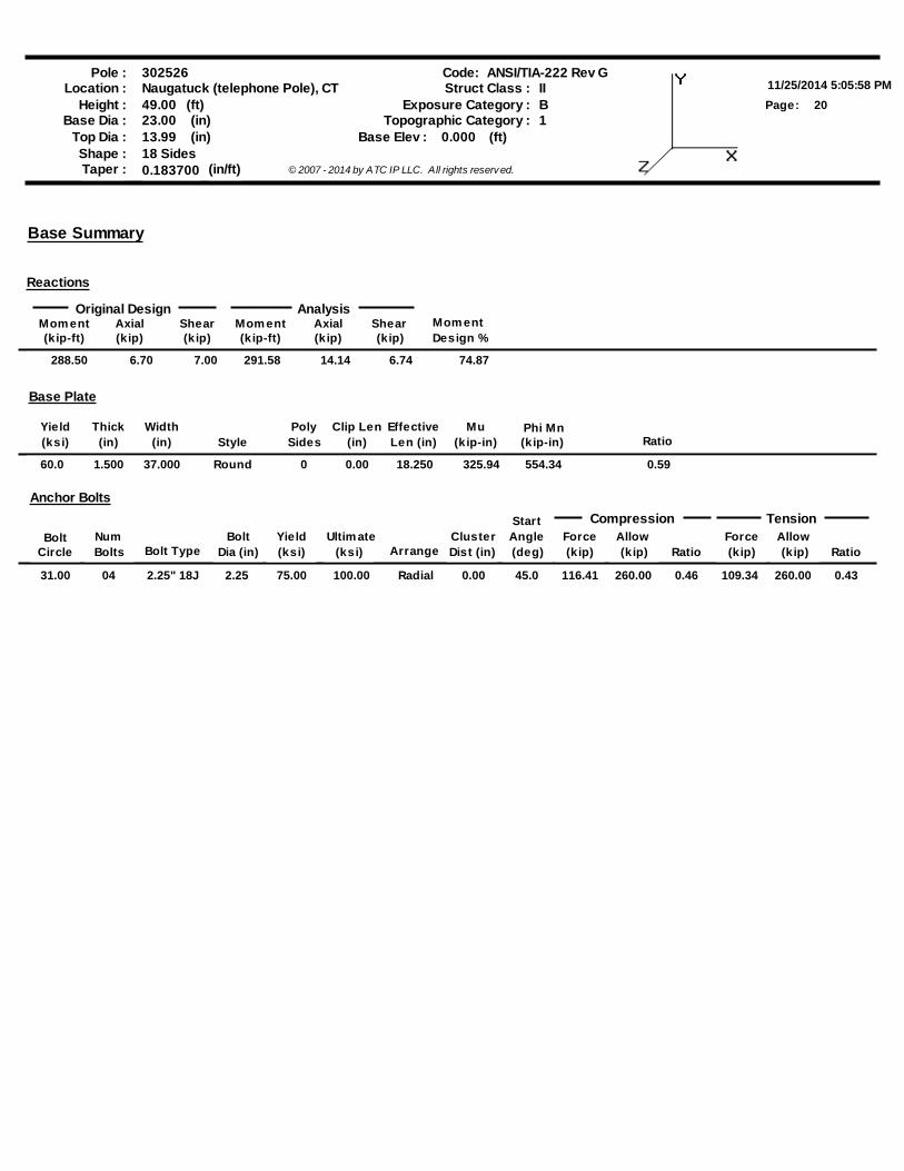
Base Summary
Reactions
Original Design AnalysisMom ent(kip-ft)
Axial(kip)
Shear(kip)
Mom ent(kip-ft)
Axial(kip)
Shear(kip)
Mom entDesign %
288.50 6.70 7.00 291.58 14.14 6.74 74.87
Phi MnRatio
Base Plate
Yield Thick WidthStyle
Poly Clip Len Effective(ksi) (in) (in) (in) Len (in)Sides
Mu(kip-in) (kip-in)
60.0 1.500 37.000 Round 0 0.00 18.250 325.94 554.34 0.59
Anchor Bolts
Bolt NumBolt Type
Bolt Yield Ultim ateArrange
ClusterStart
Force AllowRatio Ratio
TensionCompression
Circle Bolts Dia (in) (ksi)(ksi) (ksi) Dist (in)Angle(deg) (kip) (kip)
Force(kip)
Allow(kip)
31.00 04 2.25" 18J 2.25 75.00 100.00 Radial 0.00 45.0 116.41 260.00 0.46 109.34 260.00 0.43

EBI Consulting environmental | engineering | due diligence
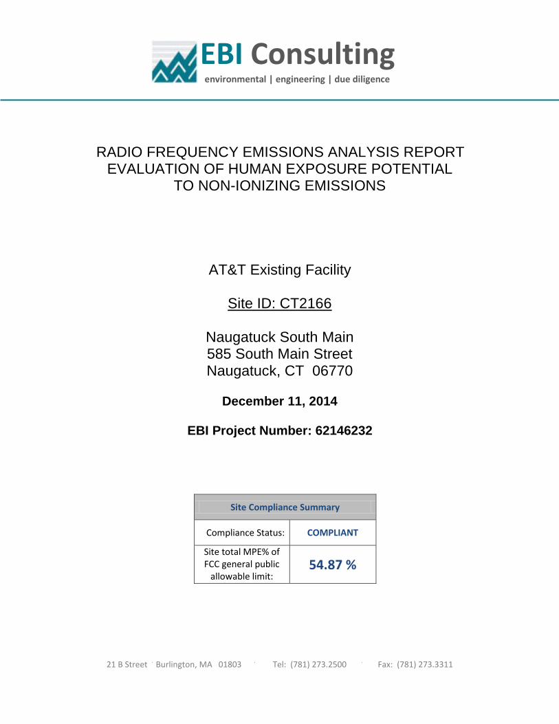
RRRADIO FREQUENCY EMISSIONS ANALYSIS REPORT EVALUATION OF HUMAN EXPOSURE POTENTIAL
TO NON-IONIZING EMISSIONS
AT&T Existing Facility
Site ID: CT2166
Naugatuck South Main 585 South Main Street Naugatuck, CT 06770
December 11, 2014
EBI Project Number: 62146232
Site Compliance Summary
Compliance Status: COMPLIANT
Site total MPE% of FCC general public
allowable limit: 54.87 %
21 B Street . Burlington, MA 01803 . Tel: (781) 273.2500 . Fax: (781) 273.3311
EBI Consulting environmental | engineering | due diligence December 11, 2014
AT&T Mobility – New England Attn: Cameron Syme 550 Cochituate Road Suite 550 – 13&14 Framingham, MA 01701
Emissions Analysis for Site: CT2166 – Naugatuck South Main
EBI Consulting was directed to analyze the proposed AT&T facility located at 585 South Main Street, Naugatuck, CT, for the purpose of determining whether the emissions from the Proposed AT&T Antenna Installation located on this property are within specified federal limits.
All information used in this report was analyzed as a percentage of current Maximum Permissible Exposure (% MPE) as listed in the FCC OET Bulletin 65 Edition 97-01and ANSI/IEEE Std C95.1. The FCC regulates Maximum Permissible Exposure in units of microwatts per square centimeter (µW/cm2). The number of µW/cm2 calculated at each sample point is called the power density. The exposure limit for power density varies depending upon the frequencies being utilized. Wireless Carriers and Paging Services use different frequency bands each with different exposure limits, therefore it is necessary to report results and limits in terms of percent MPE rather than power density.
All results were compared to the FCC (Federal Communications Commission) radio frequency exposure rules, 47 CFR 1.1307(b)(1) – (b)(3), to determine compliance with the Maximum Permissible Exposure (MPE) limits for General Population/Uncontrolled environments as defined below.
General population/uncontrolled exposure limits apply to situations in which the general public may be exposed or in which persons who are exposed as a consequence of their employment may not be made fully aware of the potential for exposure or cannot exercise control over their exposure. Therefore, members of the general public would always be considered under this category when exposure is not employment related, for example, in the case of a telecommunications tower that exposes persons in a nearby residential area.
Public exposure to radio frequencies is regulated and enforced in units of microwatts per square centimeter (μW/cm2). The general population exposure limits for the 700 MHz and 800 MHz Bands are 467 μW/cm2 and 567 μW/cm2 respectively. The general population exposure limit for the PCS and AWS bands is 1000 μW/cm2. Because each carrier will be using different frequency bands, and each frequency band has different exposure limits, it is necessary to report percent of MPE rather than power density.
21 B Street . Burlington, MA 01803 . Tel: (781) 273.2500 . Fax: (781) 273.3311
EBI Consulting environmental | engineering | due diligence Occupational/controlled exposure limits apply to situations in which persons are exposed as a consequence of their employment and in which those persons who are exposed have been made fully aware of the potential for exposure and can exercise control over their exposure. Occupational/controlled exposure limits also apply where exposure is of a transient nature as a result of incidental passage through a location where exposure levels may be above general population/uncontrolled limits (see below), as long as the exposed person has been made fully aware of the potential for exposure and can exercise control over his or her exposure by leaving the area or by some other appropriate means.
Additional details can be found in FCC OET 65.
CALCULATIONS
Calculations were done for the proposed AT&T Wireless antenna facility located at 585 South Main Street, Naugatuck, CT, using the equipment information listed below. All calculations were performed per the specifications under FCC OET 65. Since AT&T is proposing highly focused directional panel antennas, which project most of the emitted energy out toward the horizon, all calculations were performed assuming a lobe representing the maximum gain of the antenna per the antenna manufactures supplied specifications, minus 10 dB, was focused at the base of the tower. For this report the sample point is the top of a 6 foot person standing at the base of the tower.
For all calculations, all equipment was calculated using the following assumptions:
1) 2 GSM channels (850 MHz) were considered for each sector of the proposed installation. These Channels have a transmit power of 30 Watts per Channel.
2) 2 UMTS channels (PCS Band - 1900 MHz) were considered for each sector of the proposed
installation. These Channels have a transmit power of 30 Watts per Channel. 3) 2 UMTS channels (850 MHz) were considered for each sector of the proposed installation.
These Channels have a transmit power of 30 Watts per Channel. 4) 1 LTE channel (850 MHz) was considered for each sector of the proposed installation. This
channel has a transmit power of 60 Watts. 5) 1 LTE channel (PCS Band – 1900 MHz) was considered for each sector of the proposed
installation. This channel has a transmit power of 60 Watts. 6) 1 LTE channel (700 MHz Band) was considered for each sector of the proposed installation.
This channel has a transmit power of 60 Watts.
21 B Street . Burlington, MA 01803 . Tel: (781) 273.2500 . Fax: (781) 273.3311
EBI Consulting environmental | engineering | due diligence
7) All radios at the proposed installation were considered to be running at full power and were uncombined in their RF transmissions paths per carrier prescribed configuration. Per FCC OET Bulletin No. 65 - Edition 97-01 recommendations to achieve the maximum anticipated value at each sample point, all power levels emitting from the proposed antenna installation are increased by a factor of 2.56 to account for possible in-phase reflections from the surrounding environment. This is rarely the case, and if so, is never continuous.
8) For the following calculations the sample point was the top of a six foot person standing at
the base of the tower. The maximum gain of the antenna per the antenna manufactures supplied specifications minus 10 dB was used in this direction. This value is a very conservative estimate as gain reductions for these particular antennas are typically much higher in this direction.
9) The antennas used in this modeling are the Powerwave 7770 for 850 MHz and 1900 MHz (PCS) channels and the CCI OPA-65R-LCUU-H6 for 700 MHz, 850 MHz, 1900 MHz and 2300 MHz channels. This is based on feedback from the carrier with regards to anticipated antenna selection. The Powerwave 7770 has a maximum gain of 13.4 dBd for 850 MHz and 13.4 dBd for 1900 MHz at its main lobe. The CCI OPA-65R-LCUU-H6 has a maximum gain of 12.7 dBd for 700 MHz, 12.7 dBd for 850 MHz, 14.8 dBd for 1900 MHz and 15.3 dBd for 2300 MHz at its main lobe. The maximum gain of the antenna per the antenna manufactures supplied specifications, minus 10 dB, was used for all calculations. This value is a very conservative estimate as gain reductions for these particular antennas are typically much higher in this direction.
10) The antenna mounting height centerlines of the proposed antennas are 52 feet above ground
level (AGL).There are only two sectors for this AT&T facility. 11) Emissions values for additional carriers were taken from the Connecticut Siting Council
active database. Values in this database are provided by the individual carriers themselves.
All calculations were done with respect to uncontrolled / general public threshold limits.
21 B Street . Burlington, MA 01803 . Tel: (781) 273.2500 . Fax: (781) 273.3311
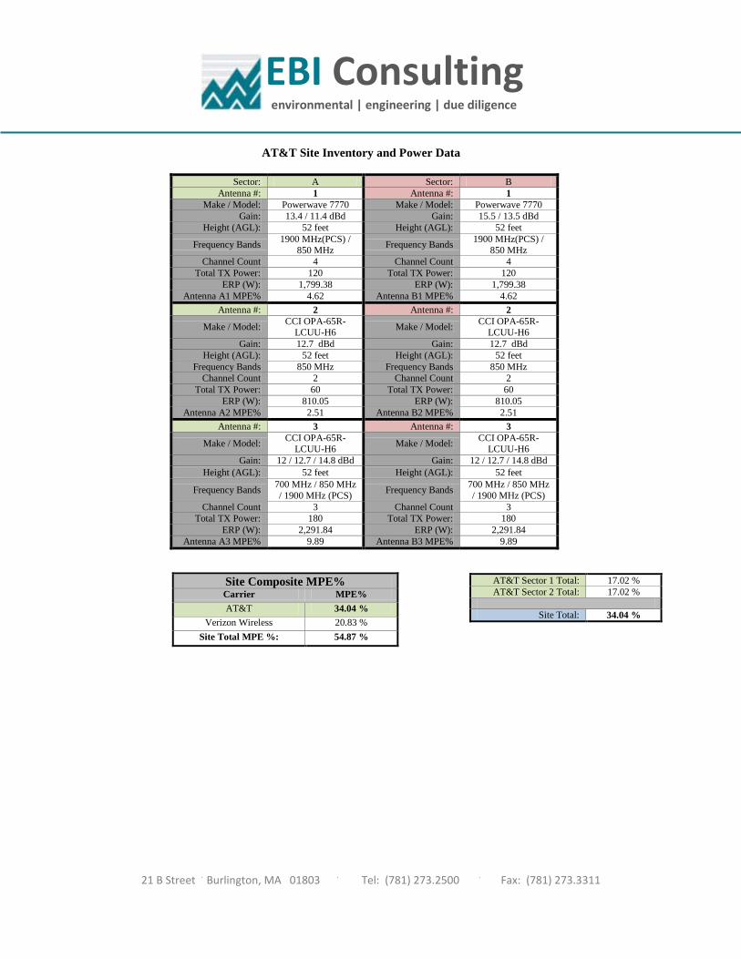
EBI Consulting environmental | engineering | due diligence AT&T Site Inventory and Power Data
Sector: A Sector: B Antenna #: 1 Antenna #: 1
Make / Model: Powerwave 7770 Make / Model: Powerwave 7770 Gain: 13.4 / 11.4 dBd Gain: 15.5 / 13.5 dBd
Height (AGL): 52 feet Height (AGL): 52 feet
Frequency Bands 1900 MHz(PCS) / 850 MHz Frequency Bands 1900 MHz(PCS) /
850 MHz Channel Count 4 Channel Count 4
Total TX Power: 120 Total TX Power: 120 ERP (W): 1,799.38 ERP (W): 1,799.38
Antenna A1 MPE% 4.62 Antenna B1 MPE% 4.62 Antenna #: 2 Antenna #: 2
Make / Model: CCI OPA-65R-LCUU-H6 Make / Model: CCI OPA-65R-
LCUU-H6 Gain: 12.7 dBd Gain: 12.7 dBd
Height (AGL): 52 feet Height (AGL): 52 feet Frequency Bands 850 MHz Frequency Bands 850 MHz
Channel Count 2 Channel Count 2 Total TX Power: 60 Total TX Power: 60
ERP (W): 810.05 ERP (W): 810.05 Antenna A2 MPE% 2.51 Antenna B2 MPE% 2.51
Antenna #: 3 Antenna #: 3
Make / Model: CCI OPA-65R-LCUU-H6 Make / Model: CCI OPA-65R-
LCUU-H6 Gain: 12 / 12.7 / 14.8 dBd Gain: 12 / 12.7 / 14.8 dBd
Height (AGL): 52 feet Height (AGL): 52 feet
Frequency Bands 700 MHz / 850 MHz / 1900 MHz (PCS) Frequency Bands 700 MHz / 850 MHz
/ 1900 MHz (PCS) Channel Count 3 Channel Count 3
Total TX Power: 180 Total TX Power: 180 ERP (W): 2,291.84 ERP (W): 2,291.84
Antenna A3 MPE% 9.89 Antenna B3 MPE% 9.89
Site Composite MPE% Carrier MPE% AT&T 34.04 %
Verizon Wireless 20.83 % Site Total MPE %: 54.87 %
AT&T Sector 1 Total: 17.02 % AT&T Sector 2 Total: 17.02 %
Site Total: 34.04 %
21 B Street . Burlington, MA 01803 . Tel: (781) 273.2500 . Fax: (781) 273.3311
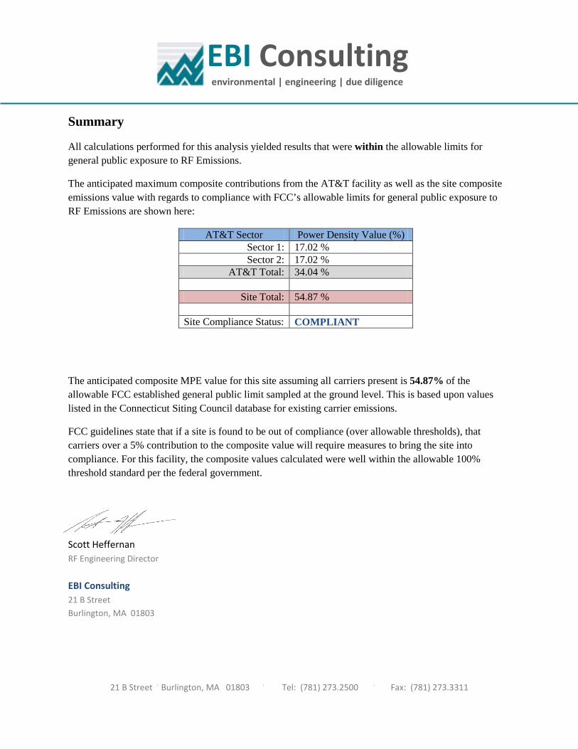
EBI Consulting environmental | engineering | due diligence Summary
All calculations performed for this analysis yielded results that were within the allowable limits for general public exposure to RF Emissions.
The anticipated maximum composite contributions from the AT&T facility as well as the site composite emissions value with regards to compliance with FCC’s allowable limits for general public exposure to RF Emissions are shown here:
AT&T Sector Power Density Value (%) Sector 1: 17.02 % Sector 2: 17.02 %
AT&T Total: 34.04 %
Site Total: 54.87 %
Site Compliance Status: COMPLIANT
The anticipated composite MPE value for this site assuming all carriers present is 54.87% of the allowable FCC established general public limit sampled at the ground level. This is based upon values listed in the Connecticut Siting Council database for existing carrier emissions.
FCC guidelines state that if a site is found to be out of compliance (over allowable thresholds), that carriers over a 5% contribution to the composite value will require measures to bring the site into compliance. For this facility, the composite values calculated were well within the allowable 100% threshold standard per the federal government.
Scott Heffernan RF Engineering Director EBI Consulting 21 B Street Burlington, MA 01803
21 B Street . Burlington, MA 01803 . Tel: (781) 273.2500 . Fax: (781) 273.3311