Embed Size (px)
Citation preview

TH Analog ATEX / IECEx / CEC / NEC / KCs / EAC Ex certified / Japanese approval / Safety SIL 2 capableOperation Manual
Temposonics®
Magnetostrictive Linear Position Sensors

2
Temposonics® TH Analog ATEX / IECEx / CEC / NEC / KCs / EAC Ex certified / Japanese approval / Safety SIL 2 capableOperation Manual
Table of contents
1. Introduction .......................................................................................................................................................31.1 Purpose and use of this manual ....................................................................................................................................................................31.2 Used symbols and warnings .........................................................................................................................................................................3
2. Safety instructions ...............................................................................................................................................32.1 Intended use ..................................................................................................................................................................................................32.2 Forseeable misuse .........................................................................................................................................................................................42.3 Installation, commissioning and operation ....................................................................................................................................................42.4 Safety instructions for use in explosion-hazardous areas .............................................................................................................................52.5 Warranty........................................................................................................................................................................................................62.6 Return ...........................................................................................................................................................................................................6
3. Identification......................................................................................................................................................73.1 Order code of Temposonics® TH ....................................................................................................................................................................73.2 Nameplate (example) ....................................................................................................................................................................................93.3 Approvals ......................................................................................................................................................................................................93.4 Scope of delivery ...........................................................................................................................................................................................9
4. Product description and commissioning ................................................................................................................... 104.1 Functionality and system design .................................................................................................................................................................104.2 Styles and installation of Temposonics® TH ................................................................................................................................................114.3 Magnet installation ......................................................................................................................................................................................174.4 Electrical connection ...................................................................................................................................................................................194.5 Frequently ordered accessories ..................................................................................................................................................................25
5. Operation........................................................................................................................................................ 285.1 Getting started .............................................................................................................................................................................................285.2 Programming and configuration .................................................................................................................................................................28
6. Maintenance and troubleshooting .......................................................................................................................... 356.1 Error conditions, troubleshooting ................................................................................................................................................................356.2 Maintenance ................................................................................................................................................................................................356.3 Repair ..........................................................................................................................................................................................................356.4 List of spare parts .......................................................................................................................................................................................356.5 Transport and storage .................................................................................................................................................................................35
7. Removal from service / dismantling ........................................................................................................................ 358. Technical data Temposonics® TH SIL 2 ..................................................................................................................... 369. Technical data Temposonics® TH standard ................................................................................................................ 3910. Declaration of conformity of standard version ........................................................................................................... 4111. Declaration of conformity of SIL 2 version ............................................................................................................... 4212. Appendix ....................................................................................................................................................... 43
3
Temposonics® TH Analog ATEX / IECEx / CEC / NEC / KCs / EAC Ex certified / Japanese approval / Safety SIL 2 capableOperation Manual
1/ The term qualified technical personnel characterizes persons who: • are familiar with the safety concepts of automation technology applicable to the particular project • are competent in the field of electromagnetic compatibility (EMC)
• have received adequate training for commissioning and service operations • are familiar with the operation of the device and know the information required for correct operation provided in the product documentation
1. Introduction
1.1 Purpose and use of this manual
Before starting the operation of Temposonics® position sensors, read this documentation thoroughly and follow the safety information. For further details on SIL 2 refer to MTS Sensors SIL 2 safety manual (part number: 551504). Keep the manual for future reference!
The content of this technical documentation and of its appendix is intended to provide information on mounting, installation and com-missioning by qualified automation personnel 1 or instructed service technicians who are familiar with the project planning and dealing with Temposonics® sensors.
1.2 Used symbols and warnings
Warnings are intended for your personal safety and for avoidance of damage to the described product or connected devices. In this doc-umentation, safety information and warnings to avoid dangers that might affect the life and health of operating or service personnel or cause material damage are highlighted by the preceding pictogram, which is defined below.
Symbol Meaning
NOTICE This symbol is used to point to situationsthat may lead to material damage, but not to personal injury.
2. Safety instructions
2.1 Intended use
This product must be used only for the applications defined under item 1 to item 4 and only in conjunction with the third-party devices and components recommended or approved by MTS Sensors. As a prerequisite of proper and safe operation, the product requires correct transport, storage, mounting and commissioning and must be operat-ed with utmost care.
1. The sensor systems of all Temposonics® series are intended exclusively for measurement tasks encountered in industrial, commercial and laboratory applications. The sensors are consid-ered as system accessories and must be connected to suitable evaluation electronics, e.g. a PLC, IPC, indicator or other electron-ic control unit.
2. The sensor’s surface temperature class is T4. 3. The EU-Type Examination Certificates and Certificates of Compli-
ance have to be taken into account including any special condition defined therein.
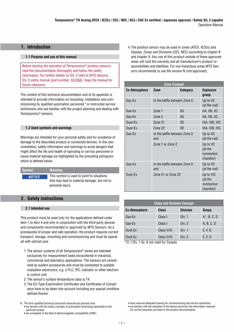
4. The position sensor may be used in zones (ATEX, IECEx) and Classes, Zones and Divisions (CEC, NEC) according to chapter 8 and chapter 9. Any use of this product outside of these approved areas will void the warranty and all manufacturer’s product re-sponsibilities and liabilities. For non-hazardous areas MTS Sen-sors recommends to use the version N (not approved).
Class and Division Concept
Ex-Atmosphere Class Division Group
Gas-Ex Class I Div. 1 A*, B, C, D
Gas-Ex Class I Div. 2 A, B, C, D
Dust-Ex Class II/III Div. 1 E, F, G
Dust-Ex Class II/III Div. 2 E, F, G*Cl. I Div. 1 Gr. A not valid for Canada
Zone Concept
Ex-Atmosphere Zone Category Explosion group
Gas-Ex In the baffle between Zone 0 Up to IIC (at the rod)
Gas-Ex Zone 1 2G IIA, IIB, IIC
Gas-Ex Zone 2 3G IIA, IIB, IIC
Dust-Ex Zone 21 2D IIIA, IIIB, IIIC
Dust-Ex Zone 22 3D IIIA, IIIB, IIIC
Gas-Ex In the baffle between Zone 0and
Up to IIC (at the rod)
Zone 1 or Zone 2 Up to IIC (at the connection chamber)
Gas-Ex In the baffle between Zone 0and
Up to IIC (at the rod)
Dust-Ex Zone 21 or Zone 22 Up to IIIC (at the connection chamber)
4
Temposonics® TH Analog ATEX / IECEx / CEC / NEC / KCs / EAC Ex certified / Japanese approval / Safety SIL 2 capableOperation Manual
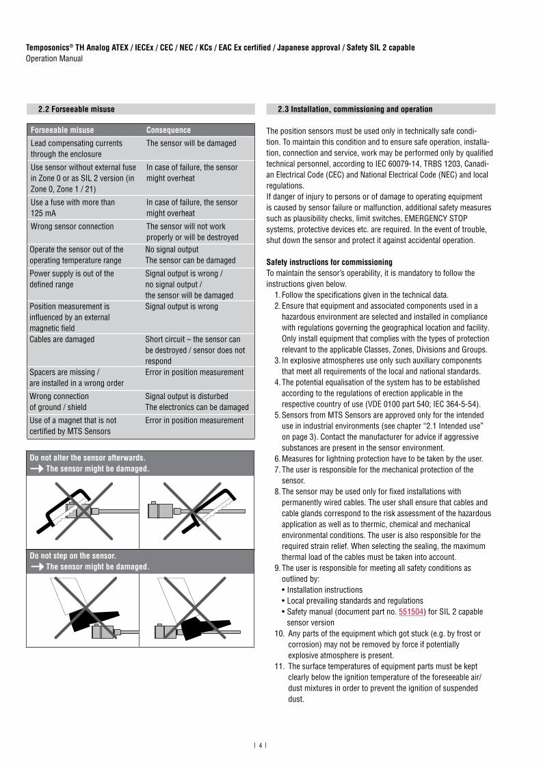
2.2 Forseeable misuse
Forseeable misuse Consequence
Lead compensating currents through the enclosure
The sensor will be damaged
Use sensor without external fuse in Zone 0 or as SIL 2 version (in Zone 0, Zone 1 / 21)
In case of failure, the sensor might overheat
Use a fuse with more than 125 mA
In case of failure, the sensor might overheat
Wrong sensor connection The sensor will not work properly or will be destroyed
Operate the sensor out of theoperating temperature range
No signal outputThe sensor can be damaged
Power supply is out of the defined range
Signal output is wrong / no signal output / the sensor will be damaged
Position measurement is influenced by an external magnetic field
Signal output is wrong
Cables are damaged Short circuit – the sensor can be destroyed / sensor does not respond
Spacers are missing / are installed in a wrong order
Error in position measurement
Wrong connection of ground / shield
Signal output is disturbedThe electronics can be damaged
Use of a magnet that is not certified by MTS Sensors
Error in position measurement
Do not step on the sensor. The sensor might be damaged.
Do not alter the sensor afterwards. The sensor might be damaged.
2.3 Installation, commissioning and operation
The position sensors must be used only in technically safe condi-tion. To maintain this condition and to ensure safe operation, installa-tion, connection and service, work may be performed only by qualified technical personnel, according to IEC 60079-14, TRBS 1203, Canadi-an Electrical Code (CEC) and National Electrical Code (NEC) and local regulations. If danger of injury to persons or of damage to operating equipmentis caused by sensor failure or malfunction, additional safety measuressuch as plausibility checks, limit switches, EMERGENCY STOPsystems, protective devices etc. are required. In the event of trouble,shut down the sensor and protect it against accidental operation.
Safety instructions for commissioningTo maintain the sensor’s operability, it is mandatory to follow the instructions given below.
1. Follow the specifications given in the technical data. 2. Ensure that equipment and associated components used in a
hazardous environment are selected and installed in compliance with regulations governing the geographical location and facility. Only install equipment that complies with the types of protection relevant to the applicable Classes, Zones, Divisions and Groups.
3. In explosive atmospheres use only such auxiliary components that meet all requirements of the local and national standards.
4. The potential equalisation of the system has to be established according to the regulations of erection applicable in the respective country of use (VDE 0100 part 540; IEC 364-5-54).
5. Sensors from MTS Sensors are approved only for the intended use in industrial environments (see chapter “2.1 Intended use” on page 3). Contact the manufacturer for advice if aggressive substances are present in the sensor environment.
6. Measures for lightning protection have to be taken by the user. 7. The user is responsible for the mechanical protection of the
sensor. 8. The sensor may be used only for fixed installations with
permanently wired cables. The user shall ensure that cables and cable glands correspond to the risk assessment of the hazardous application as well as to thermic, chemical and mechanical environmental conditions. The user is also responsible for the required strain relief. When selecting the sealing, the maximum thermal load of the cables must be taken into account.
9. The user is responsible for meeting all safety conditions as outlined by:• Installation instructions• Local prevailing standards and regulations• Safety manual (document part no. 551504) for SIL 2 capable
sensor version 10. Any parts of the equipment which got stuck (e.g. by frost or
corrosion) may not be removed by force if potentially explosive atmosphere is present.
11. The surface temperatures of equipment parts must be kept clearly below the ignition temperature of the foreseeable air/ dust mixtures in order to prevent the ignition of suspended dust.

5
Temposonics® TH Analog ATEX / IECEx / CEC / NEC / KCs / EAC Ex certified / Japanese approval / Safety SIL 2 capableOperation Manual
How to ensure safe commissioning 1. Protect the sensor against mechanical damage during
installation and operation. 2. Do not use damaged products and secure them against uninten-
tional commissioning. Mark damaged products as being defective.
3. Prevent electrostatic charges. 4. Do not use the sensor in cathodic systems for corrosion
protection. Do not allow parasitic currents on the sensor housing. 5. Switch off the supply voltage prior to disconnecting or
connecting the connectors. 6. Connect the sensor very carefully and pay attention to the
polarity of connections, power supply as well as to the shape and duration of control pulses.
7. Cable entry temperature and branching point temperature may reach 104 °C (219 °F) and 116 °C (241 °F) respectively. Select suitable cable and entry device.
8. For field wiring, use cables suitable for the service temperature range of −40 °C (−40 °F) to +116 °C (241 °F).
9. Do not open when energized. Open the sensor only as shown in Fig. 7 on page 13.
10. A seal shall be installed within 18" of the enclosure (for NEC / CEC only).
11. Use only approved power supplies of Category II according to IEC 61010-1.
12. Ensure that the specified permissible limit values of the sensor for operating voltage, environmental conditions, etc. are met.
13. Make sure that:• the sensor and associated components were installed
according to the instructions• the sensor enclosure is clean• all screws (only those of quality 6.8, A2-50 or A4-50 are
allowed) are tightened according to specified fastening torque in Fig. 7
• the cable glands certified according to the required hazardous area classification and IP protection are tightened according to the manufacture’s specifications
• surfaces limiting the joint shall not be machined or painted subsequently (flameproof enclosure)
• surfaces limiting the joint have not been provided with a seal (flameproof enclosure)
• the magnet does not grind on the rod. This could cause damage to the magnet and the sensor rod. If there is contact between the moving magnet (including the magnet holder) and the sensor rod, make sure that the maximum speed of the moving magnet is less or equal 1 m/s.
14. Ground the sensor via one of the two ground lugs. Both the sensor and the moving magnet including magnet holder must be connected to protective ground (PE) to avoid electrostatic discharge (ESD).
15. Before applying power, ensure that nobody’s safety is jeopardized by starting machines.
16. Check the function of the sensor regularly and provide documentation of the checks (see chapter “6.2 Maintenance” on page 35).
2.4 Safety instructions for use in explosion-hazardous areas
The sensor has been designed for operation inside explosion-hazard-ed areas. It has been tested and left the factory in a condition in which it is safe to operate. Relevant regulations and standards have been observed. According to the marking (ATEX, IECEx, CEC, NEC, KCs, EAC Ex, Japanese approval) the sensor is approved only for operation in defined hazardous areas (see chapter “2.1 Intended use” on page 3). The SIL 2 version cannot be adjusted by the customer.
When do you need an external fuse?
How to install a T-Series sensor in Zone 0 according to the guide-lines (ATEX, IECEx, CEC, NEC, EAC Ex, KCs Japanese approval)
1. Install an external fuse in compliance with IEC 127 outside the Ex-atmosphere. Connect it upstream to the equipment. Current: 125 mA
2. Install the sensor housing in Zone 1, Zone 2, Zone 21 or Zone 22. Only the rod section (for version D, G, and E) can extend into Zone 0.
3. Follow the safety regulations detailed in IEC/EN 60079-26, ANSI/ISA 60079-26 (12.00.03), ANSI/ISA/IEC/EN 60079-10-1 and JNIOSH-TR-46-2 to ensure isolation between Zone 0 and Zone 1.
4. When installing the TH sensor in the boundary wall for Zone 0, the corresponding requirements in ANSI/ISA/IEC/EN 60079-26 and ANSI/ISA/IEC/EN 60079-10-1 have to be noticed. Thereby the screw-in thread is to be sealed gas tightly (IP67) according to ANSI/ISA/IEC/EN 60079-26 and ANSI/ISA/IEC/EN 60079-10-1.
Zone / Div. T-Series standard sensor T-Series SIL 2 sensor
Zone 0 (rod only)
External fuse required External fuse required
Zone 1 / 21 No additional fuse External fuse required
Zone 2 / 22 No additional fuse No additional fuse
Div. 1 External fuse recommended
External fuse recommended

6
Temposonics® TH Analog ATEX / IECEx / CEC / NEC / KCs / EAC Ex certified / Japanese approval / Safety SIL 2 capableOperation Manual
2.5 Warranty
MTS Sensors grants a warranty period for the Temposonics®
position sensors and supplied accessories relating to materialdefects and faults that occur despite correct use in accordance withthe intended application 2. The MTS Sensors obligation is limited torepair or replacement of any defective part of the unit. No warrantycan be provided for defects that are due to improper use or aboveaverage stress of the product, as well as for wear parts. Under nocircumstances will MTS Sensors accept liability in the event of offenseagainst the warranty rules, no matter if these have been assured orexpected, even in case of fault or negligence of the company.MTS Sensors explicitly excludes any further warranties. Neitherthe company’s representatives, agents, dealers nor employees areauthorized to increase or change the scope of warranty.
2.6 Return
For diagnostic purposes, the sensor can be returned to MTS Sensors.Any shipment cost is the responsibility of the sender 2. For a corre-sponding form, see chapter “12. Appendix” on page 43.
2/ See also applicable MTS Sensors terms of sales and delivery on www.mtssensors.com

7
Temposonics® TH Analog ATEX / IECEx / CEC / NEC / KCs / EAC Ex certified / Japanese approval / Safety SIL 2 capableOperation Manual
3. Identification
3.1 Order code of Temposonics® TH
T H 1 N
a b c d e f g h i
a Sensor model
T H Rod
b Design
Enclosure Type 3:TH rod sensor with housing material stainless steel 1.4305 (AISI 303) and rod material stainless steel 1.4306 (AISI 304L)
M Threaded flange with flat-face (M18×1.5-6g)
N Threaded flange with raised-face (M18×1.5-6g)
S Threaded flange with flat-face (¾"-16 UNF-3A)
T Threaded flange with raised-face (¾"-16 UNF-3A)
Enclosure Type 3X:TH rod sensor with housing material stainless steel 1.4404 (AISI 316L) and rod material stainless steel 1.4404 (AISI 316L)
F Threaded flange with flat-face (¾"-16 UNF-3A)
G Threaded flange with raised-face (¾"-16 UNF-3A)
W Threaded flange with flat-face (M18×1.5-6g)
d Connection type
C 0 1 Side connection with thread ½"-14 NPT (All versions)
C 1 0 Top connection with thread ½"-14 NPT (All versions)
M 0 1 Side connection with thread M16×1.5-6H (Version E & N)
M 1 0 Top connection with thread M16×1.5-6H(Version E & N)
N 0 1 Side connection with thread M20×1.5-6H (All versions)
N 1 0 Top connection with thread M20×1.5-6H(All versions)
N F 1 Side connection with thread M20×1.5-6H (Version E & N)Note: Not available for SIL 2 version!
See next pagee
*/ Non standard stroke lengths are available; must be encoded in 5 mm / 0.1 in. increments
c Stroke length
X X X X M 0025…1500 mm (SIL 2)
X X X X U 001.0…060.0 in. (SIL 2).
Standard stroke length (mm)* Ordering steps
25 … 500 mm 5 mm
500 … 750 mm 10 mm
750…1000 mm 25 mm
1000…1500 mm 50 mm
Standard stroke length (in.)* Ordering steps
1 …20 in. 0.2 in.
20 …30 in. 0.4 in.
30 …40 in. 1.0 in.
40 …60 in. 2.0 in.
1 2 3 4 5 6 7 8 9 10 11 12 13 14 15 16 17 18
c Stroke length (continued)
X X X X M 0025…7620 mm (standard)
X X X X U 001.0…300.0 in. (standard).
Standard stroke length (mm)* Ordering steps
25 … 500 mm 5 mm
500 … 750 mm 10 mm
750…1000 mm 25 mm
1000…2500 mm 50 mm
2500…5000 mm 100 mm
5000…7620 mm 250 mm
Standard stroke length (in.)* Ordering steps
1 … 20 in. 0.2 in.
20 … 30 in. 0.4 in.
30 … 40 in. 1.0 in.
40…100 in. 2.0 in.
100…200 in. 4.0 in.
200…300 in. 10.0 in.

8
Temposonics® TH Analog ATEX / IECEx / CEC / NEC / KCs / EAC Ex certified / Japanese approval / Safety SIL 2 capableOperation Manual
NOTICE
Use magnets of the same type (e.g. 2 ring magnets with part no. 201 542-2 ) for multi-position measurement.
e Operating voltage
1 +24 VDC (−15 / +20 %)
fVersion (see chapter 8 and chapter 9 for further information)
D Ex db and Ex tb (A/F 55)
E Ex db eb and Ex tb (A/F 55)US & CA approval: Ex nA /NI (for Zone 2 and 22)(Note: US & CA approval is only available for SIL 2 version)
G Ex db and Ex tb (A/F 60)US & CA approvals: Explosionproof (XP) (Note: Group A is not available for Canada)
N Not approved
g Functional safety type
N Not approved
S SIL 2 (with certificate and manual)
h Additional option type
N None
i Output
1 output with 1 position magnet Output 1 (position magnet 1) (Available outputs for SIL 2: A01 and A11)
A 0 1 4…20 mA
A 1 1 20…4 mA
A 2 1 0…20 mA
A 3 1 20…0 mA
2 outputs with 1 position magnetOutput 1 (position magnet 1) + output 2 (position magnet 1)Notice: Not available for SIL 2 version!
A 0 3 4…20 mA 20…4 mA
2 outputs with 2 position magnetsOutput 1 (position magnet 1) + output 2 (position magnet 2) Notice: Not available for SIL 2 version!
A 0 2 4…20 mA 4…20 mA
A 1 2 20…4 mA 20…4 mA
A 2 2 0…20 mA 0…20 mA
A 3 2 20…0 mA 20…0 mA

9
Temposonics® TH Analog ATEX / IECEx / CEC / NEC / KCs / EAC Ex certified / Japanese approval / Safety SIL 2 capableOperation Manual
3.2 Nameplate (example)
3.3 Approvals
See chapter “8. Technical data Temposonics® TH SIL 2” on page 36 ff and chapter “9. Technical data Temposonics® TH standard” on page 39 ff..
3.4 Scope of delivery
TH (rod sensor):• Sensor
Fig. 1: Example of a nameplate of a TH sensor (SIL 2 version)
Fig. 2: Example of a nameplate of a TH sensor (standard version)
Fig. 3: Label for japanese approval
NOTICE
For a detailed overview of the certifications, see www.mtssensors.com
CML 17JPN1072X
MTS Sensors
労(平29年7月)検
THN0080MC011DSNA11In: 24 VDC 100 mA YofC: 26/2018Out: 20-4 mAEnclosure type 3 S/N: 18260255
CML ATEX1090XIECEx CML 16.0039X
II 1/2G Ex db IIC T4 Ga/Gb II 1G/2D Ex tb IIIC T130 °C Ga/Db
18-KA4BO-0247X 18-KA4BO-0248X
−40 °C ≤ Ta ≤ 85 °C IP66 / IP67
Датчик серии Т ОС ВО ЗАО ТИБР№TC RU С-DE.ГБ08.B.01976Ga/Gb Ex db IIC T4 XDa/Db Ex tb IIIC T130 °C X
THN0080MC011ESNA11In: 24 VDC 100 mA YofC: 26/2018Out: 20-4 mAEnclosure type 3 S/N: 18260255
CML ATEX1090XIECEx CML 16.0039X
II 1/2G Ex db eb IIC T4 Ga/Gb II 1G/2D Ex tb IIIC T130 °C Ga/Db
18-KA4BO-0249X 18-KA4BO-0250XClass I, Div. 2, Groups A, B, C, D T4Class II/III, Div. 2, Groups E, F, G T130 °CEx nA / AEx nA IIC T4 Gc Ex tc / AEx tc IIIC T130 °C Dc
−40 °C ≤ Ta ≤ 80 °C IP66 / IP67
Датчик серии Т ОС ВО ЗАО ТИБР№TC RU С-DE.ГБ08.B.01976Ga/Gb Ex db eb IIC T4 XDa/Db Ex tb IIIC T130 °C X
THN0080MC011GSNA11In: 24 VDC 100 mA YofC: 26/2018Out: 20-4 mAEnclosure type 3 S/N: 18260255
CML ATEX1090XIECEx CML 16.0039X
II 1/2G Ex db IIC T4 Ga/Gb II 1G/2D Ex tb IIIC T 130 °C Ga/Db
18-KA4BO-0247X 18-KA4BO-0248XClass I, Div. 1, Groups A, B, C, D T4Class II/III, Div. 1, Groups E, F, G T130 °CClass I, Zone 0/1 AEx d / Ex d IIC T4Class II/III, Zone 21 AEx tb / Ex tb IIIC T130 °CGroup A is not approved for Canada
−40 °C ≤ Ta ≤ 85 °C IP66 / IP67
Датчик серии Т ОС ВО ЗАО ТИБР№TC RU С-DE.ГБ08.B.01976Ga/Gb Ex db IIC T4 XDa/Db Ex tb IIIC T130 °C X
Variant with flameproof connection chamberVersion D
Variant with increased safety connection chamberVersion E
Variant with flameproof / explosionproofconnection chamberVersion G
THN0080MC011DNNA11In: 24 VDC 100 mA YofC: 26/2018Out: 20-4 mAEnclosure type 3 S/N: 18260255
CML ATEX1090XIECEx CML 16.0039X
II 1/2G Ex db IIC T4 Ga/Gb II 1G/2D Ex tb IIIC T130 °C Ga/Db
18-KA4BO-0247X 18-KA4BO-0248X
−40 °C ≤ Ta ≤ 75 °C IP66 / IP67
Датчик серии Т ОС ВО ЗАО ТИБР№TC RU С-DE.ГБ08.B.01976Ga/Gb Ex db IIC T4 XDa/Db Ex tb IIIC T130 °C X
THN0080MC011ENNA11In: 24 VDC 100 mA YofC: 26/2018Out: 20-4 mAEnclosure type 3 S/N: 18260255
CML ATEX1090XIECEx CML 16.0039X
II 1/2G Ex db eb IIC T4 Ga/Gb II 1G/2D Ex tb IIIC T130 °C Ga/Db
18-KA4BO-0249X 18-KA4BO-0250X
Датчик серии Т ОС ВО ЗАО ТИБР№TC RU С-DE.ГБ08.B.01976Ga/Gb Ex db eb IIC T4 XDa/Db Ex tb IIIC T130 °C X
−40 °C ≤ Ta ≤ 75 °C IP66 / IP67
THN0080MC011GNNA11In: 24 VDC 100 mA YofC: 26/2018Out: 20-4 mAEnclosure type 3 S/N: 18260255
CML ATEX1090XIECEx CML 16.0039X
II 1/2G Ex db IIC T4 Ga/Gb II 1G/2D Ex tb IIIC T 130 °C Ga/Db
18-KA4BO-0247X 18-KA4BO-0248XClass I, Div. 1, Groups A, B, C, D T4Class II/III, Div. 1, Groups E, F, G T130 °CClass I, Zone 0/1 AEx d / Ex d IIC T4Class II/III, Zone 21 AEx tb / Ex tb IIIC T130 °CGroup A is not approved for Canada
−40 °C ≤ Ta ≤ 75 °C IP66 / IP67
Датчик серии Т ОС ВО ЗАО ТИБР№TC RU С-DE.ГБ08.B.01976Ga/Gb Ex db IIC T4 XDa/Db Ex tb IIIC T130 °C X
Variant with flameproof connection chamberVersion D
Variant with increased safety connection chamberVersion E
Variant with flameproof / explosionproofconnection chamberVersion G

10
Temposonics® TH Analog ATEX / IECEx / CEC / NEC / KCs / EAC Ex certified / Japanese approval / Safety SIL 2 capableOperation Manual
4.1 Functionality and system design
Product designation• Position sensor Temposonics® T-Series
Sensor model• Temposonics® TH (rod sensor)
Stroke length• Stroke length SIL 2 version: 25…1500 mm (1…60 in.)• Stroke length standard version: 25…7620 mm (1…300 in.)
Output signal• Analog
ApplicationTemposonics® position sensors are used for measurement and conver-sion of the length (position) variable in the fields of automated systems and mechanical engineering. The T-Series sensors are designed for installation in a raised or flat-face flanged hydraulic cylinder, for use as an open-air position sensor or as a liquid level sensor with the addition of a float.
Principle of operation and system constructionThe absolute, linear position sensors provided by MTS Sensorsrely on the company’s proprietary Temposonics® magnetostrictivetechnology, which can determine position with a high level ofprecision and robustness. Each Temposonics® position sensorconsists of a ferromagnetic waveguide, a position magnet, a strainpulse converter and supporting electronics. The magnet, connectedto the object in motion in the application, generates a magnetic fieldat its location on the waveguide. A short current pulse is applied tothe waveguide. This creates a momentary radial magnetic field andtorsional strain on the waveguide. The momentary interaction of themagnetic fields releases a torsional strain pulse that propagates thelength of the waveguide. When the ultrasonic wave reaches the end ofthe waveguide it is converted into an electrical signal. Since the speedof the ultrasonic wave in the waveguide is precisely known, the timerequired to receive the return signal can be converted into a linearposition measurement with both high accuracy and repeatability.
Fig. 4: Time-of-flight based magnetostrictive position sensing principle
4. Product description and commissioning
T-Series modelsThe T-Series is available in four variations, three of which are hazardous classifications: • Flameproof housing with flameproof connection chamber (version D) • Flameproof (explosionproof) housing with flameproof (explosion-
proof) connection chamber (version G)• Flameproof housing with increased safety connection chamber
(version E) • Non-hazardous (version N)
All of these variations are available in two types of hardware / software, SIL 2 compliant and standard, both in 4…20 mA and 20…4 mA out-put. The sensor assembly is offered in 1.4305 (AISI 303) stainless steel and in 1.4404 (AISI 316L). Associated with hazardous rating the sensor meets IP66 / IP67. For non-hazardous environments the sensor meets IP66, IP67, IP68, IP69K and NEMA 4X.
5
Sensing element (Waveguide)
Position magnet (Magnetic fi eld) Torsional strain pulse converter
4
Current pulsegenerates magnetic fi eld
Interaction with position magnet fi eld generates torsional strainpulse Torsional strain
pulse propagatesStrain pulse detected by converter
Time-of-fl ight converted into position
1
2
3

11
Temposonics® TH Analog ATEX / IECEx / CEC / NEC / KCs / EAC Ex certified / Japanese approval / Safety SIL 2 capableOperation Manual
Fig. 5: Temposonics® TH with ring magnet
4.2 Styles and installation of Temposonics® TH
Threaded flange with raised-face
Version D & G
2.5(0.1)
(2.01)
Null zone51
Sensor electronics housing132.5(5.22)
Mag
net
Ø 10
± 0
.13
(Ø 0
.39
± 0.
01)
Refer to “Table 1” for “TH rod sensor threaded flange type references”
A
BC
Version D77 (3.03)
83.8 (3.29)55 (2.17)
Version G82 (3.23)
89.2 (3.51)60 (2.36)
A
B
C
Version D: A/F 55Version G: A/F 60
See order code section “d” for connection types
M18×1.5-6g:Ø 23.8 ± 0.2 (Ø 0.94 ± 0.01)¾"-16 UNF-3A:Ø 25.4 ± 0.2 (Ø 1 ± 0.01)
22.5(0.89)
Stroke lengthStandard: 25…7620 (1…300)
SIL 2: 25…1500 (1…60)
Dead zone63.5 (2.5) /66* (2.6)*
* Stroke length > 5000 mm (196.9 in.)
on page 12
Version E & N
2.5(0.1)
83.8(3.29)
73(2
.87) 55
(2.1
7)
Null zone51
(2.01)
Sensor electronics housing112.5(4.43)
Mag
net
Ø 10
± 0
.13
(Ø 0
.39
± 0.
01)
Refer to “Table 1” for“TH rod sensor threaded flange type references”
A/F 55
See order code section “d” for connection types
M18×1.5-6g:Ø 23.8 ± 0.2 (Ø 0.94 ± 0.01)¾"-16 UNF-3A:Ø 25.4 ± 0.2 (Ø 1 ± 0.01)
22.5(0.89)
Stroke lengthStandard: 25…7620 (1…300)
SIL 2: 25…1500 (1…60)
Dead zone63.5 (2.5) / 66* (2.6)*
* Stroke length > 5000 mm (196.9 in.)
Threaded flange with flat-face
Version D & G Null zone51
(2.01)
Sensor electronics housing132.5(5.22)
83.8(3.29)
55
(2.1
7)
73
(2.8
7)
Sensor electronics housing112.5(4.43)
Null zone51
(2.01)
Refer to “Table 1” for“TH rod sensor threaded flange type references”
Refer to “Table 1” for“TH rod sensor threaded flange type references”
Ø 10
± 0
.13
(Ø 0
.39
± 0.
01)
Ø 10
± 0
.13
(Ø 0
.39
± 0.
01)
A
BC
Version D77 (3.03)
83.8 (3.29)55 (2.17)
Version G82 (3.23)
89.2 (3.51)60 (2.36)
A
B
C
Version D: A/F 55Version G: A/F 60
A/F 55
Mag
net
Mag
net
See order code section “d” for connection types
See order code section “d” for connection types
22.5(0.89)
22.5(0.89)
Stroke lengthStandard: 25…7620 (1…300)
SIL 2: 25…1500 (1…60)
Stroke lengthStandard: 25…7620 (1…300)
SIL 2: 25…1500 (1…60)
Dead zone63.5 (2.5) /66* (2.6)*
Dead zone63.5 (2.5) /66* (2.6)*
* Stroke length > 5000 mm (196.9 in.)
* Stroke length > 5000 mm (196.9 in.)
on page 12
Version E & N
Null zone51
(2.01)
Sensor electronics housing132.5(5.22)
83.8(3.29)
55
(2.1
7)
73
(2.8
7)
Sensor electronics housing112.5(4.43)
Null zone51
(2.01)
Refer to “Table 1” for“TH rod sensor threaded flange type references”
Refer to “Table 1” for“TH rod sensor threaded flange type references”
Ø 10
± 0
.13
(Ø 0
.39
± 0.
01)
Ø 10
± 0
.13
(Ø 0
.39
± 0.
01)
A
BC
Version D77 (3.03)
83.8 (3.29)55 (2.17)
Version G82 (3.23)
89.2 (3.51)60 (2.36)
A
B
C
Version D: A/F 55Version G: A/F 60
A/F 55
Mag
net
Mag
net
See order code section “d” for connection types
See order code section “d” for connection types
22.5(0.89)
22.5(0.89)
Stroke lengthStandard: 25…7620 (1…300)
SIL 2: 25…1500 (1…60)
Stroke lengthStandard: 25…7620 (1…300)
SIL 2: 25…1500 (1…60)
Dead zone63.5 (2.5) /66* (2.6)*
Dead zone63.5 (2.5) /66* (2.6)*
* Stroke length > 5000 mm (196.9 in.)
* Stroke length > 5000 mm (196.9 in.)
on page 12
on page 12
Controlling design dimensions are in millimeters and measurements in ( ) are in inches

12
Temposonics® TH Analog ATEX / IECEx / CEC / NEC / KCs / EAC Ex certified / Japanese approval / Safety SIL 2 capableOperation Manual
Table 1: TH rod sensor threaded flange type references
Fig. 6: Temposonics® TH connection options
Threaded flange type
Description Threaded flange
F Threaded flange with flat-faceStainless steel 1.4404 (AISI 316L) ¾"-16 UNF-3A
G Threaded flange with raised-faceStainless steel 1.4404 (AISI 316L) ¾"-16 UNF-3A
MThreaded flange with flat-faceStainless steel 1.4305 (AISI 303)
M18×1.5-6g
N Threaded flange with raised-face Stainless steel 1.4305 (AISI 303) M18×1.5-6g
SThreaded flange with flat-faceStainless steel 1.4305 (AISI 303)
¾"-16 UNF-3A
TThreaded flange with raised-faceStainless steel 1.4305 (AISI 303)
¾"-16 UNF-3A
W Threaded flange with flat-faceStainless steel 1.4404 (AISI 316L) M18×1.5-6g
Side connection C01 / N01 / NF1 (with adapter) / M01 (without adapter)
Mag
net
Connection length22 mm (0.87 in.) for version D & G18 mm (0.7 in.) for version E & N
Side connectionC01 / N01:Connector on 6 different positions at 60° eachNF1:Connector on 4 different positions at 60° each
Top connection C10 / N10 (with adapter) / M10 (without adapter)
Top connectionTop connection
Mag
net
Connection length22 mm (0.87 in.) for version D & G18 mm (0.7 in.) for version E & N

13
Temposonics® TH Analog ATEX / IECEx / CEC / NEC / KCs / EAC Ex certified / Japanese approval / Safety SIL 2 capableOperation Manual
Fig. 7: Temposonics® TH exploded view drawing
NOTICE
Connect cable to sensorSee page 22 ff. for more details.
Change orientation of cable bushing (C01, M01, N01, NF1) Loosen the five hexagonal screws M4 (A/F 3) and remove the upper lid (Fig. 7). Then loosen the six hexagonal screws M4 (A/F 3) of the connection adapter (Fig. 7). Change the orientation of the connector on six different positions at 60° each. Note the example on page 22 ff..
Part Fastening torque
1 Screw M4×10 1.2 Nm
2 Screw M4×40 1.2 Nm
3 Earthing connection: M5×8 for mounting 2.5 Nm
Version D & G
3
Connection adapter
2
1
O-ring
Upper lid
Version E & N
3
Connection adapter
2
1
Upper lid
O-ring

14
Temposonics® TH Analog ATEX / IECEx / CEC / NEC / KCs / EAC Ex certified / Japanese approval / Safety SIL 2 capableOperation Manual
Fig. 8: Temposonics® TH Zone classification
NOTICE
Seal sensor according to ingress protection IP67 between Zone 0 and Zone 1.
Version D & G (example: Threaded fl ange with raised-face) Flameproof (explosionproof) housing with fl ameproof (explosionproof) connection chamber Version D: ATEX / IECEx / EAC Ex / Japanese ApprovalVersion G: ATEX / IECEx / CEC / NEC / EAC Ex / Japanese Approval
Zone 1 Zone 0
Mag
net
Version E (example: Threaded fl ange with raised-face)Flameproof housing with increased safety connection chamber SIL 2: ATEX / IECEx / CEC / NEC / EAC Ex / Japanese ApprovalStandard: ATEX / IECEx / EAC Ex / Japanese Approval
Zone 1 Zone 0
Mag
net

15
Temposonics® TH Analog ATEX / IECEx / CEC / NEC / KCs / EAC Ex certified / Japanese approval / Safety SIL 2 capableOperation Manual
Fig. 9: Connection options
Fig. 10: SIL 2 identification
Connection options for version D & G Connection options for version E & N
C01 C10 C01 C10
½"-14 NPT½"-14 NPT ½"-14 NPT½"-14 NPT½"-14 NPT½"-14 NPT ½"-14 NPT½"-14 NPT
Side connection with thread ½"-14 NPT
Top connection with thread ½"-14 NPT
Side connection with thread ½"-14 NPT
Top connection with thread ½"-14 NPT
N01 N10 M01 M10
M20×1.5-6H M20×1.5-6HM16×1.5-6H M16×1.5-6H
Side connection with thread M20×1.5-6H
Top connection with thread M20×1.5-6H
Side connection with thread M16×1.5-6H
Top connection with thread M16×1.5-6H
N01 N10
M20×1.5-6H M20×1.5-6H
Side connection with thread M20×1.5-6H
Top connection with thread M20×1.5-6H
NF1
M20×1.5-6H
Side connectionwith thread M20×1.5-6H
16
Temposonics® TH Analog ATEX / IECEx / CEC / NEC / KCs / EAC Ex certified / Japanese approval / Safety SIL 2 capableOperation Manual
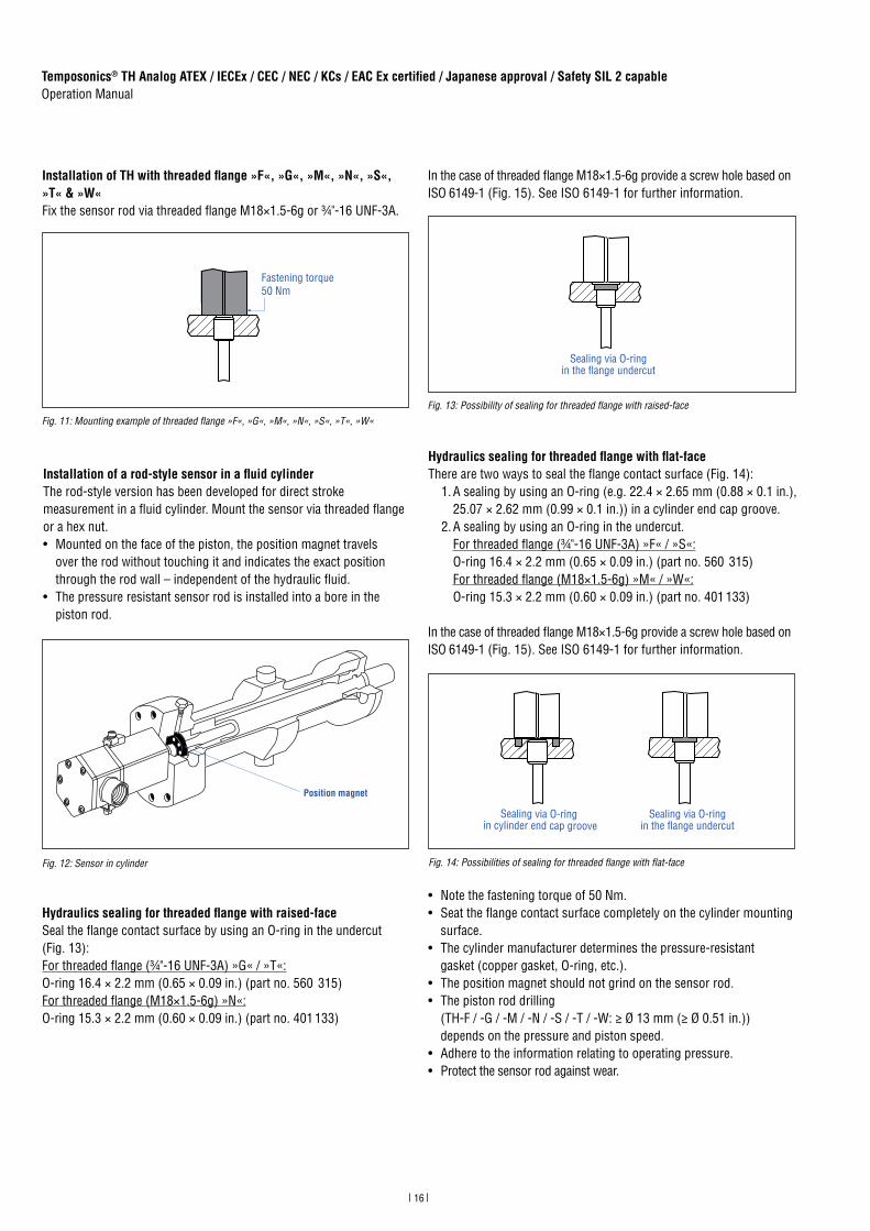
Installation of TH with threaded flange »F«, »G«, »M«, »N«, »S«, »T« & »W« Fix the sensor rod via threaded flange M18×1.5-6g or ¾"-16 UNF-3A.
Fig. 11: Mounting example of threaded flange »F«, »G«, »M«, »N«, »S«, »T«, »W«
Installation of a rod-style sensor in a fluid cylinderThe rod-style version has been developed for direct stroke measurement in a fluid cylinder. Mount the sensor via threaded flange or a hex nut. • Mounted on the face of the piston, the position magnet travels
over the rod without touching it and indicates the exact position through the rod wall – independent of the hydraulic fluid.
• The pressure resistant sensor rod is installed into a bore in the piston rod.
Fig. 12: Sensor in cylinder
Hydraulics sealing for threaded flange with raised-faceSeal the flange contact surface by using an O-ring in the undercut (Fig. 13): For threaded flange (¾"-16 UNF-3A) »G« / »T«: O-ring 16.4 × 2.2 mm (0.65 × 0.09 in.) (part no. 560 315) For threaded flange (M18×1.5-6g) »N«: O-ring 15.3 × 2.2 mm (0.60 × 0.09 in.) (part no. 401 133)
In the case of threaded flange M18×1.5-6g provide a screw hole based on ISO 6149-1 (Fig. 15). See ISO 6149-1 for further information.
Fig. 13: Possibility of sealing for threaded flange with raised-face
Hydraulics sealing for threaded flange with flat-faceThere are two ways to seal the flange contact surface (Fig. 14):
1. A sealing by using an O-ring (e.g. 22.4 × 2.65 mm (0.88 × 0.1 in.), 25.07 × 2.62 mm (0.99 × 0.1 in.)) in a cylinder end cap groove.
2. A sealing by using an O-ring in the undercut. For threaded flange (¾"-16 UNF-3A) »F« / »S«: O-ring 16.4 × 2.2 mm (0.65 × 0.09 in.) (part no. 560 315) For threaded flange (M18×1.5-6g) »M« / »W«: O-ring 15.3 × 2.2 mm (0.60 × 0.09 in.) (part no. 401 133)
In the case of threaded flange M18×1.5-6g provide a screw hole based on ISO 6149-1 (Fig. 15). See ISO 6149-1 for further information.
Fig. 14: Possibilities of sealing for threaded flange with flat-face
• Note the fastening torque of 50 Nm.• Seat the flange contact surface completely on the cylinder mounting
surface.• The cylinder manufacturer determines the pressure-resistant
gasket (copper gasket, O-ring, etc.).• The position magnet should not grind on the sensor rod.• The piston rod drilling
(TH-F / -G / -M / -N / -S / -T / -W: ≥ Ø 13 mm (≥ Ø 0.51 in.)) depends on the pressure and piston speed.
• Adhere to the information relating to operating pressure.• Protect the sensor rod against wear.
Fastening torque50 Nm
Position magnet
Sealing via O-ringin the flange undercut
Sealing via O-ringin the flange undercut
Sealing via O-ring in cylinder end cap groove

17
Temposonics® TH Analog ATEX / IECEx / CEC / NEC / KCs / EAC Ex certified / Japanese approval / Safety SIL 2 capableOperation Manual
Fig. 15: Notice for metric threaded flange M18×1.5-6g based on DIN ISO 6149-1
Controlling design dimensions are in millimeters
Notice for metric threaded flanges
Thread(d1×P)
d2 d3 d4 d5
+0.10
L1
+0.40
L2 L3 L4 Z°
±1°
TH-M / -N / -WM18×1.5-6g 65 13 24.5 19.8 2.4 28.5 2 26 15°
Ød5
Ra 3.2
Ra 3.2
Pitch diameter
A
A
Thread (d1 × P)
Ød3(Reference)
A
Ød2
Ød4(Gauging)
This dimension applies when tap drill cannot pass throughentire boss.
≤ R0
.4
R0.3
R0.1
Z°
45° ±
5°
L 3
L 1
L 2 L 4
A0.1 A0.2
4.3 Magnet installation
NOTICE
Mount ring magnets and U-magnets concentrically.Do not exceed the maximum acceptable gap (Fig. 17).
Typical use of magnets
Mounting ring magnets & U-magnetsInstall the magnet using non-magnetic material for mounting device, screws, spacers etc.. The magnet must not grind on the sensor rod. Alignment errors are compensated via the air gap.• Permissible surface pressure: Max. 40 N/mm2
• Fastening torque for M4 screws: 1 Nm; use washers, if necessary• Minimum distance between position magnet and any magnetic
material has to be 15 mm (0.6 in.) (Fig. 18). • If no other option exists and magnetic material is used, observe the
specified dimensions (Fig. 18).
Magnet Benefits
Ring magnets • Rotationally symmetrical magnetic field
U-magnets • Height tolerances can be compensated
Floats • For liquid level measurement
Fig. 16: Typical use of magnets
Magnet mounting with magnetic materialWhen using magnetic material the dimensions of Fig. 18 must be observed.A. If the position magnet aligns with the drilled piston rodB. If the position magnet is secured into the drilled piston rod using
a snap ring (circlip) of magnetic material, install another non-magnetic spacer (e.g. part no. 400 633) between the magnet and the snap ring (circlip).
Fig. 18: Installation with magnetic material
Controlling design dimensions are in millimeters and measurements in ( ) are in inches
Fig. 17: Mounting of U-magnet (part no. 251 416-2 or part no. 201 553)
M4 1
2
Air gap
Concentric mountingof U-magnet
Part no. 201 553:3 ±1 (0.12 ±0.04)
Part no. 251 416-2:1.75 ±1 (0.07 ±0.04)
U-magnet
Non-magnetic mounting plate and fasteners
1
2
Magnet Magnet
1
2
3 3
A B
Magneticmaterial
1 Null zone (see Fig. 20)
2 Distance between position magnet and any magnetic material (≥ 15 mm (≥ 0.6 in.))
3 Non-magnetic spacer (≥ 5 mm (≥ 0.2 in.)) – Recommendation: 8 mm (0.31 in.)

18
Temposonics® TH Analog ATEX / IECEx / CEC / NEC / KCs / EAC Ex certified / Japanese approval / Safety SIL 2 capableOperation Manual
NOTICE
On all sensors, the areas left and right of the active stroke length are provided for null and dead zone (see “4.2 Styles and installation of Temposonics® TH” on page 11). These zones should not be used for measurement, however the active stroke length can be exceeded.
Controlling design dimensions are in millimeters and measurements in ( ) are in inches
Sensors with stroke lengths ≥ 1 meter (3.3 ft.) Support horizontally installed sensors with a stroke length from 1 meter (3.3 ft.) mechanically at the rod end. Without the use of a support, rod and posi tion magnet may be damaged. A false measurement result is also possi ble. Longer rods require evenly distributed mechanical support over the entire length (e.g. part no. 561 481). Use an U-magnet (Fig. 19) for measurement.
Start and end positions of the position magnetsConsider the start and end positions of the position magnets during the installation. To ensure that the entire stroke length is electrically usable, the position magnet must be mechanically mounted as follows.
Mounting floatsA stop collar is ordered separately with a float. The stop collar con-sists of material, which is below the specific gravity of the fluid. It is designed to keep the float out of the dead zone. The placement of the stop collar is dependent on the float and placement of the magnet within the float. If your application requires measuring to the bottom of your vessel, ask MTS Sensors about our low lift-off float option which can measure less than 25 mm (1 in.) of liquid.
Multi-position measurementThe minimum distance between the magnets is 75 mm (3 in.).
NOTICE
Use magnets of the same type (e.g. two ring magnets with part no. 201 542-2) for multi-position measurement.
Fig. 19: Example of sensor support (part no. 561 481)
Fig. 20: Start and end positions of magnets
Fig. 21: Minimum distance for multi-position measurement
Fig. 22: Liquid level measurement
U-magnet
Sensor rod
Non-magnetic fixing clip
TH with ring magnet & U-magnet
Reference edge of mounting
Start position51 (2.01)
End position63.5 / 66* (2.5 / 2.6*)
* Stroke length > 5000 mm (196.9 in.)
Activemeasuring range
Dead zone
Measuring rangeA
B
C Float
D Stop collar
B
A
C
D
TH with ring magnet & U-magnet
≥ 75 (≥ 3)
19
Temposonics® TH Analog ATEX / IECEx / CEC / NEC / KCs / EAC Ex certified / Japanese approval / Safety SIL 2 capableOperation Manual
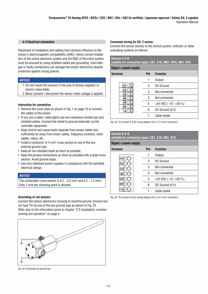
4.4 Electrical connection
Placement of installation and cabling have decisive influence on thesensor‘s electromagnetic compatibility (EMC). Hence correct installa-tion of this active electronic system and the EMC of the entire system must be ensured by using shielded cables and grounding. Overvolta-ges or faulty connections can damage the sensor electronics despite protection against wrong polarity.
Instruction for connection• Remove the cover plate as shown in Fig. 7 on page 13 to connect
the cables to the sensor.• If you use a cable / cable gland use low-resistance twisted pair and
shielded cables. Connect the shield to ground externally via the controller equipment.
• Keep control and signal leads separate from power cables and sufficiently far away from motor cables, frequency inverters, valve cables, relays, etc..
• Install a conductor of 4 mm2 cross section to one of the two external ground lugs.• Keep all non-shielded leads as short as possible.• Keep the ground connections as short as possible with a large cross
section. Avoid ground loops.• Use only stabilized power supplies in compliance with the specified
electrical ratings.
NOTICE
1. Do not mount the sensors in the area of strong magnetic or electric noise fields.
2. Never connect / disconnect the sensor when voltage is applied.
NOTICE
The contactable cross section is 0.2…2.5 mm² and 0.2…1.5 mm². Only 1 wire per clamping point is allowed.
Connector wiring for SIL 2 sensorConnect the sensor directly to the control system, indicator or other evaluating systems as follows:
Version E & Nsuitable for connection types: C01, C10, M01, M10, N01, N10
Signal + power supply
Terminal Pin Function
1 Output
2 DC Ground
3 Not connected
4 Not connected
5 +24 VDC (−15 / +20 %)
6 DC Ground (0 V)
7 Cable shield
Version D & Gsuitable for connection types: C01, C10, N01, N10
Signal + power supply
Terminal Pin Function
1 Output
2 DC Ground
3 Not connected
4 Not connected
5 +24 VDC (−15 / +20 %)
6 DC Ground (0 V)
7 Cable shield
Grounding of rod sensorsConnect the sensor electronics housing to machine ground. Ground sen-sor type TH via one of the two ground lugs as shown in Fig. 23. Refer also to the information given in chapter “2.3 Installation, commis-sioning and operation” on page 4.
Fig. 23: Grounding via ground lug
Fig. 24: TH (version E & N) wiring diagram SIL 2 (1.5 mm2 conductor)
Fig. 25: TH (version D & G) wiring diagram SIL 2 (2.5 mm2 conductor)
20
Temposonics® TH Analog ATEX / IECEx / CEC / NEC / KCs / EAC Ex certified / Japanese approval / Safety SIL 2 capableOperation Manual
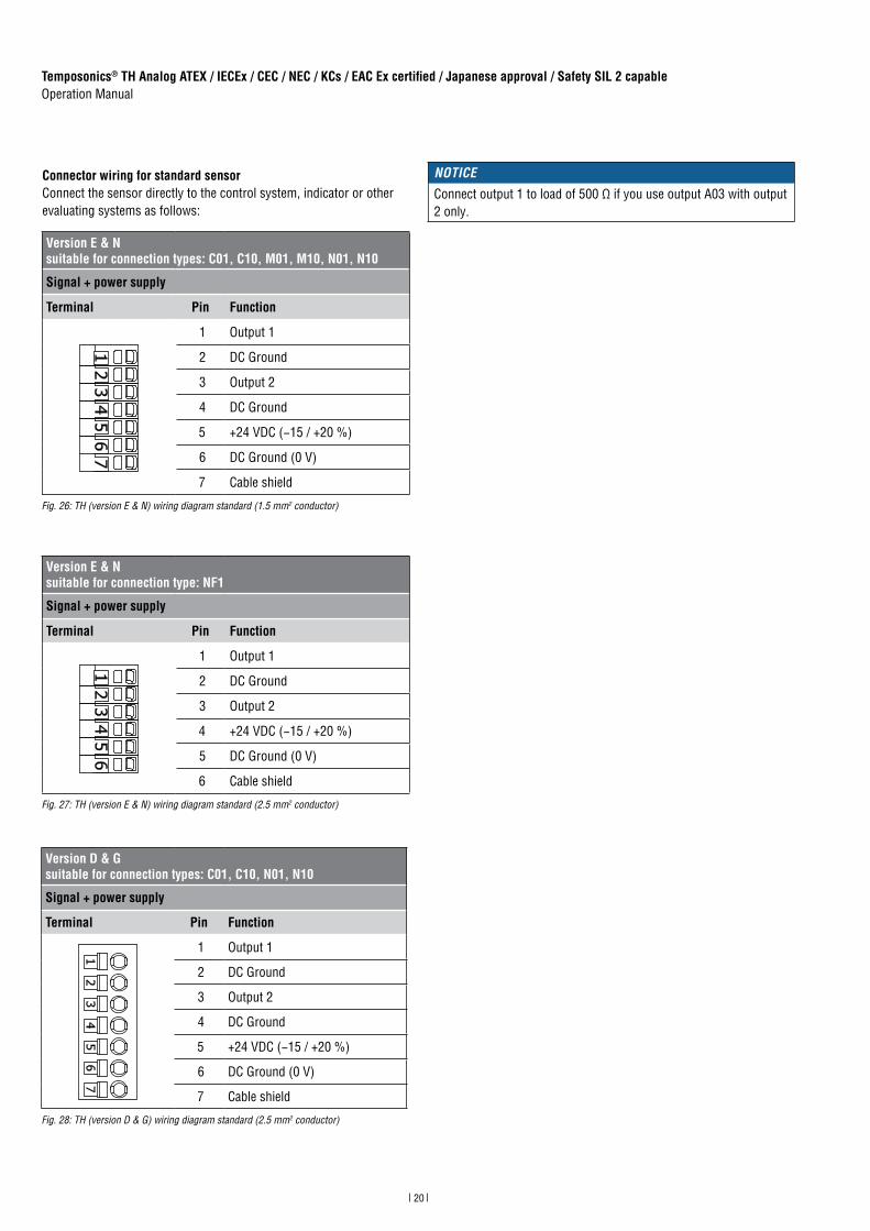
Connector wiring for standard sensorConnect the sensor directly to the control system, indicator or other evaluating systems as follows:
Version E & Nsuitable for connection types: C01, C10, M01, M10, N01, N10
Signal + power supply
Terminal Pin Function
1 Output 1
2 DC Ground
3 Output 2
4 DC Ground
5 +24 VDC (−15 / +20 %)
6 DC Ground (0 V)
7 Cable shield
Version E & Nsuitable for connection type: NF1
Signal + power supply
Terminal Pin Function
1 Output 1
2 DC Ground
3 Output 2
4 +24 VDC (−15 / +20 %)
5 DC Ground (0 V)
6 Cable shield
Fig. 26: TH (version E & N) wiring diagram standard (1.5 mm2 conductor)
Fig. 27: TH (version E & N) wiring diagram standard (2.5 mm2 conductor)
Version D & Gsuitable for connection types: C01, C10, N01, N10
Signal + power supply
Terminal Pin Function
1 Output 1
2 DC Ground
3 Output 2
4 DC Ground
5 +24 VDC (−15 / +20 %)
6 DC Ground (0 V)
7 Cable shield
Fig. 28: TH (version D & G) wiring diagram standard (2.5 mm2 conductor)
NOTICE
Connect output 1 to load of 500 Ω if you use output A03 with output 2 only.

21
Temposonics® TH Analog ATEX / IECEx / CEC / NEC / KCs / EAC Ex certified / Japanese approval / Safety SIL 2 capableOperation Manual
Fig. 29: Installation wiring diagram for side connection and top connection (example: Side connection)
Output
DC Ground
Not connected
Not connected
+24 VDC (−15 / +20 %)
DC Ground (0 V)
Hazardous areaNon-hazardous area
GroundExternal fuse
Ground
Note chapter 2.4 on page 5

22
Temposonics® TH Analog ATEX / IECEx / CEC / NEC / KCs / EAC Ex certified / Japanese approval / Safety SIL 2 capableOperation Manual
Cable connection (only for versions E and N)
Recommended tools
Electric torque screwdriver 3 mm (0.12 in.), fastening torque 1.2 Nm
Torque wrenchtorque depending on cable gland
Slotted screwdriver2.0 × 40 mm (0.08 × 1.57 in.)
Crimping toolfor ferrules with max. 2.5 mm2
1Strip the cable for 60 mm (2.36 in.).
2Install the shrink hose and the ferrules (max. 1.5 mm2 or max. 2.5 mm2 depending on connection).
Step 1: Preparing of cable
Length of shrink hose:20 mm (0.79 in.)
Length of shrink hose:40 mm (1.57 in.)
The following two options present how to connect the cable to the T-Series sensor:
Option 1: Cable connection via disassembly of connection adapter (see page 23)Option 2: Cable connection without disassembly of connection adapter (see page 24)
The figures are examples. Variations are possible, e.g. different cable colors
NOTICE
The example “Cable connection” is only valid for version E and N of the TH sensor. Refer to the corresponding installation requirements and local regulations, if you like to connect a cable to the TH sensor versions D and G.
23
Temposonics® TH Analog ATEX / IECEx / CEC / NEC / KCs / EAC Ex certified / Japanese approval / Safety SIL 2 capableOperation Manual
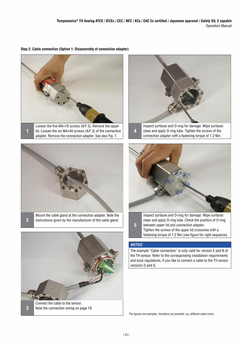
Step 2: Cable connection (Option 1: Disassembly of connection adapter)
2Mount the cable gland at the connection adapter. Note the instructions given by the manufacturer of the cable gland.
1Loosen the five M4×10 screws (A/F 3). Remove the upper lid. Loosen the six M4×40 screws (A/F 3) of the connection adapter. Remove the connection adapter. See also Fig. 7.
5
Inspect surfaces and O-ring for damage. Wipe surfaces clean and apply O-ring lube. Check the position of O-ring between upper lid and connection adapter.Tighten the screws of the upper lid crosswise with a fastening torque of 1.2 Nm (see figure for right sequence).
1
2
3
4
5
3Connect the cable to the sensor. Note the connection wiring on page 19.
4Inspect surfaces and O-ring for damage. Wipe surfaces clean and apply O-ring lube. Tighten the screws of the connection adapter with a fastening torque of 1.2 Nm.
The figures are examples. Variations are possible, e.g. different cable colors
NOTICE
The example “Cable connection” is only valid for version E and N of the TH sensor. Refer to the corresponding installation requirements and local regulations, if you like to connect a cable to the TH sensor versions D and G.

24
Temposonics® TH Analog ATEX / IECEx / CEC / NEC / KCs / EAC Ex certified / Japanese approval / Safety SIL 2 capableOperation Manual
Step 2: Cable connection (Option 2: Without disassembly of connection adapter)
1Loosen the five M4×10 screws (A/F 3).
2Mount the cable and cable gland. Note the instructions given by the manufacturer of the cable gland.
3Connect the cable to the sensor. Note the connection wiring on page 19.
4
Inspect surfaces and O-ring for damage. Wipe surfaces clean and apply O-ring lube. Check the position of O-ring between upper lid and connection adapter.Tighten the screws of the upper lid crosswise with a fastening torque of 1.2 Nm (see figure for right sequence).
1
2
3
4
5
The figures are examples. Variations are possible, e.g. different cable colors
NOTICE
The example “Cable connection” is only valid for version E and N of the TH sensor. Refer to the corresponding installation requirements and local regulations, if you like to connect a cable to the TH sensor versions D and G.
25
Temposonics® TH Analog ATEX / IECEx / CEC / NEC / KCs / EAC Ex certified / Japanese approval / Safety SIL 2 capableOperation Manual
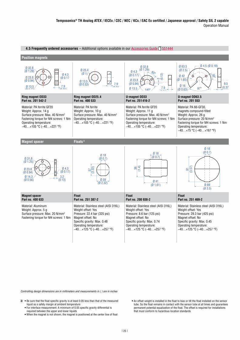
4.5 Frequently ordered accessories
3/ • Be sure that the float specific gravity is at least 0.05 less than that of the measured liquid as a safety margin at ambient temperature • For interface measurement: A minimum of 0.05 specific gravity differential is required between the upper and lower liquids • When the magnet is not shown, the magnet is positioned at the center line of float
• An offset weight is installed in the float to bias or tilt the float installed on the sensor tube. So the float remains in contact with the sensor tube at all times and guarantees permanent potential equalization of the float. The offset is required for installations that must conform to hazardous location standards
Position magnets
Ø 32.8(Ø 1.29)
Ø 23.8(Ø 0.94)
Ø 13.5(Ø 0.53)
Ø 4.3(Ø 0.17)
7.9(0.31)
Ø 25.4(Ø 1)
Ø 13.5(Ø 0.53) 7.9
(0.31)
Ø 32.8(Ø 1.29)
Ø 23.8(Ø 0.94)
Ø 13.5(Ø 0.53)
Ø 4.3(Ø 0.17)
60°
140°
3 (0.1
2)
7.9(0.31)
Ø 4.5 (Ø 0.18)Ø 63.5(Ø 2.5)
Ø 42(Ø 1.65)
Ø 16(Ø 0.63) 97°
30°
9.5(0.37)
Ring magnet OD33Part no. 201 542-2
Ring magnet OD25.4Part no. 400 533
U-magnet OD33Part no. 251 416-2
U-magnet OD63.5Part no. 201 553
Material: PA ferrite GF20Weight: Approx. 14 gSurface pressure: Max. 40 N/mm2
Fastening torque for M4 screws: 1 NmOperating temperature: −40…+105 °C (−40…+221 °F)
Material: PA ferriteWeight: Approx. 10 gSurface pressure: Max. 40 N/mm2
Operating temperature: −40…+105 °C (−40…+221 °F)
Material: PA ferrite GF20Weight: Approx. 11 gSurface pressure: Max. 40 N/mm2
Fastening torque for M4 screws: 1 NmOperating temperature: −40…+105 °C (−40…+221 °F)
Material: PA 66-GF30, magnets compound-fi lledWeight: Approx. 26 gSurface pressure: 20 N/mm2
Fastening torque for M4 screws: 1 NmOperating temperature:−40…+75 °C (−40…+167 °F)
Magnet spacer Floats 3
Ø 14.3(Ø 0.56)
Ø 23.8(Ø 0.94)
Ø 31.8(Ø 1.25)
Ø 4.3(Ø 0.17)
3.2(0.13)
Ø 18(Ø 0.7)
57(2
.22)
Ø 59(Ø 2.32)
Ø 18(Ø 0.7)
Ø 41(Ø 1.61)
36 (1.4
)
Ø 18(Ø 0.7)
Ø 89(Ø 3.5)
91(3
.57)
Magnet spacerPart no. 400 633
FloatPart no. 251 387-2
FloatPart no. 200 938-2
FloatPart no. 251 469-2
Material: Aluminum Weight: Approx. 5 gSurface pressure: Max. 20 N/mm2
Fastening torque for M4 screws: 1 Nm
Material: Stainless steel (AISI 316L)Weight offset: YesPressure: 22.4 bar (325 psi)Magnet offset: NoSpecifi c gravity: Max. 0.48Operating temperature: −40…+125 °C (−40…+257 °F)
Material: Stainless steel (AISI 316L)Weight offset: YesPressure: 8.6 bar (125 psi)Magnet offset: NoSpecifi c gravity: Max. 0.74Operating temperature: −40…+125 °C (−40…+257 °F)
Material: Stainless steel (AISI 316L)Weight offset: YesPressure: 29.3 bar (425 psi)Magnet offset: NoSpecifi c gravity: Max. 0.45Operating temperature: −40…+125 °C (−40…+257 °F)
– Additional options available in our Accessories Guide 551444
Controlling design dimensions are in millimeters and measurements in ( ) are in inches

26
Temposonics® TH Analog ATEX / IECEx / CEC / NEC / KCs / EAC Ex certified / Japanese approval / Safety SIL 2 capableOperation Manual
4/ • Be sure that the float specific gravity is at least 0.05 less than that of the measured liquid as a safety margin at ambient temperature • For interface measurement: A minimum of 0.05 specific gravity differential is required between the upper and lower liquids • When the magnet is not shown, the magnet is positioned at the center line of float
• An offset weight is installed in the float to bias or tilt the float installed on the sensor tube. So the float remains in contact with the sensor tube at all times and guarantees permanent potential equalization of the float. The offset is required for installations that must conform to hazardous location standards
Controlling design dimensions are in millimeters and measurements in ( ) are in inches
Float 4
Ø 18(Ø 0.7)
50(1
.96)
Ø 47(Ø 1.83)
54(2
.11)
Ø 18(Ø 0.7)
31
(1.2
2)
27(1
.06)
Ø 47(Ø 1.83)
Ø 18(Ø 0.7)
Ø 47(Ø 1.85)
77(3
.01)
Ø 18(Ø 0.7)
Ø 47(Ø 1.85)
77(3
.01)
FloatPart no. 201 605-2
FloatPart no. 201 606-2
FloatPart no. 251 982-2
FloatPart no. 251 983-2
Material: Stainless steel 1.4571 (AISI 316 Ti)Weight offset: YesPressure: 4 bar (60 psi)Magnet offset: YesSpecifi c gravity: Max. 0.6Operating temperature: −40…+125 °C (−40…+257 °F)
Material: Stainless steel 1.4571 (AISI 316 Ti)Weight offset: YesPressure: 4 bar (60 psi)Magnet offset: YesSpecifi c gravity: 0.93 ± 0.01Operating temperature:−40…+125 °C (−40…+257 °F)
Material: Stainless steel (AISI 316L)Weight offset: YesPressure: 29.3 bar (425 psi)Magnet offset: NoSpecifi c gravity: 0.93 ± 0.01Operating temperature: −40…+125 °C (−40…+257 °F)
Material: Stainless steel (AISI 316L)Weight offset: YesPressure: 29.3 bar (425 psi)Magnet offset: NoSpecifi c gravity: 1.06 ± 0.01Operating temperature: −40…+125 °C (−40…+257 °F)
Standard float that can be expedited Standard float that can be expedited
Float 4 Collar Optional installation hardware
Ø 18(Ø 0.7)
Ø 47(Ø 1.85)
77(3
.01)
4(0.16)
Ø 27(Ø 1.06) Ø 10
(Ø 0.39) 5
(0.2)
9(0.35)
8-32 threads
8(0.31)
20 (0
.79)
60 (2.36)16 (0.63)
12 (0
.47)
3.2 (0.13)
Ø 3.2 (Ø 0.13)M3 fastening screws (6×)
FloatPart no. 251 981-2
StoppkragenArtikelnr. 560 777
Fixing clip for rod with Ø 10 mmPart no. 561 481
Material: Stainless steel (AISI 316L)Weight offset: YesPressure: 29.3 bar (425 psi)Magnet offset: No Specifi c gravity: Max. 0.67Operating temperature: −40…+125 °C (−40…+257 °F)
Provides end of stroke stops for fl oatMaterial: Stainless steel 1.4301 (AISI 304)Weight: Approx. 30 gHex key 7⁄64" required
Application: Used to secure sensor rods (Ø 10 mm (Ø 0.39 in.)) when using an U-magnet or block magnetMaterial: Brass, non-magnetic

27
Temposonics® TH Analog ATEX / IECEx / CEC / NEC / KCs / EAC Ex certified / Japanese approval / Safety SIL 2 capableOperation Manual
Manuals, Software & 3D Models available at: www.mtssensors.com
Controlling design dimensions are in millimeters and measurements in ( ) are in inches
O-rings
Ø 15.3(Ø 0.6)
Ø 2.2(Ø 0.09)
Ø 16.4(Ø 0.65)
Ø 2.2(Ø 0.09)
O-ring for threaded fl ange M18×1.5-6gPart no. 401 133
O-ring for threaded fl ange ¾"-16 UNF-3APart no. 560 315
Material: Fluoroelastomer Durometer: 75 ± 5 Shore AOperating temperature:−40…+204 °C (−40…+400 °F)
Material: Fluoroelastomer Durometer: 75 ± 5 Shore AOperating temperature:−40…+204 °C (−40…+400 °F)
Programming tools (for standard version, SIL 2 version cannot be programmed)
Hand programmer for analog outputPart no. 253 124
Programming kit Part no. 253 134-1
Cabinet programmer for analog outputPart no. 253 408
Easy teach-in-setups of stroke lengthand direction on desired zero / spanpositions. For sensors with 1 magnet.
Kit includes: 1 × interface converter box, 1 × power supply 1 × cable (60 cm) with M16 female connector (6 pin), straight – D-sub female connector (9 pin), straight1 × cable (60 cm) with 3 × terminal clamp – D-sub female connector (9 pin), straight
For sensors with 1 or 2 magnets.
Software is available at:www.mtssensors.com
Features snap-in mounting on standard DIN rail (35 mm). This programmer can be permanently mounted in a control cabinet and includes a program / run switch. For sensors with 1 magnet.

28
Temposonics® TH Analog ATEX / IECEx / CEC / NEC / KCs / EAC Ex certified / Japanese approval / Safety SIL 2 capableOperation Manual
5. Operation
5.1 Getting started
The sensor is factory-set to its order sizes and adjusted, i.e. the requi-red output signal corresponds exactly to the selected stroke length.
Example: Output 4…20 mA = 0…100 % stroke length
NOTICE If necessary, the TH analog standard sensors can be re-adjusted using the service tools described below. To install the connection cable, the sensor’s upper lid needs to be removed as shown in Fig. 7 on page 13. It is not possible to configure the T-Series SIL 2 sensors.
5.2 Programming and configuration
Analog interfaceThe analog sensor can be directly connected to a controller. Its elect-ronics generates a position signal output proportional to the start and end of the active measuring range.
Step 1: Connect hand programmerStep 2: Adjust measuring range
NOTICE
Observe during commissioning 1. Before switching on for the first time, check carefully to ensure
the sensor has been connected correctly. 2. Ensure that the sensor control system cannot react in an
uncontrolled way when switching on. 3. Ensure that the sensor is ready and in operation mode after
switching on. 4. Check the pre-set span start and end values of the measuring
range (see section 4.2 Styles and installation of Temposonics® TH) and correct them via the customer’s control system, if necessary or via the MTS Sensors service tools. The operation of the service tools is described in detail on the following pages.
NOTICE The programming tools are not approved for use in a hazardous environment.
NOTICE The T-Series (only standard version) can be configured with the programming tools listed below. The T-Series SIL 2 rated sen-sor is not a field programmable device. All sensor parameters are fac-tory-set and not adjustable by the end user.
5.2.1 Analog hand programmer, part no. 253 124
Connect the hand programmer directly to the sensor. When measuring with one magnet it is possible to change the start and end positions as well as the measuring direction via simple teach-in process, see also “5.2.4 Setting examples for programming tools” on page 34. After that, the changed parameters are stored in the sensor. Move the mag-net to the desired null and span positions (minimum distance between setpoints: 25 mm (1 in.)) and push the corresponding 0 % respectively 100 % buttons on the programmer. The individual steps are explained in the following section.
Connect the hand programmer to the power supply and to the sensoraccording to Fig. 32.MTS Sensors programming tools
Temposonics® sensors can be adapted to modified measurement tasks very easily from outside via the connecting leads – without opening the sensor. Various MTS Sensors programming tools from the list of ac-cessories (see page 27) are available for this purpose.
Fig. 30: Analog interface
Fig. 31: Active measuring range
Fig. 32: Connect hand programmer (see connection wiring Fig. 26 / Fig. 27 / Fig. 28 on page 20)
Pin 1, GY
When acitvated power supply, the green LED lights up permanently.
Version E & N, 2.5 mm2 Version E & N, 1.5 mm2
Version D & G, 2.5 mm2
Pin 3, YE
Pin 5, BNPin 6, WH
24 VDC0 VDC
0 %
100 %
Start24 VDC
0 V / GND
Pin 5, BN Pin 1, GYPin 3, YEPin 6, WH
Start
0 %100 %
1
2
3
4
5
6
Pin 1, GY
76
Pin 3, YE
Pin 4, BNPin 5, WH
0 %
100 %
Start24 VDC
0 V / GND
1
2
3
4
5
Active measuring rangeStroke length
0 % 100 %Magnet positionOutput 1: Position
x: Position0Active measuring range
y: mA

29
Temposonics® TH Analog ATEX / IECEx / CEC / NEC / KCs / EAC Ex certified / Japanese approval / Safety SIL 2 capableOperation Manual
Step 1: Connect hand programmerStep 2: Adjust measuring range
1. Activate the programming mode:• Press “Start” button and “100 %” button simultaneously• Release “Start” button first, wait 1 second and release
“100 %” button
2. Set start point (0 % output) (Fig. 34):• Set the position magnet on start position• Press and release the “0 %” button
NOTICE
You can only adapt magnet 1 via hand programmer. In order tochange the settings of magnet 1 you have to connect both outputs(output 1 and output 2).
Fig. 33: Adjust measuring range
Fig. 34: Determine start and end position
3. Set end point (100 % output) (Fig. 34):• Set the position magnet on end position• Press and release the “100 %” button
4. Back to normal function (operation mode):• Press “Start” button• Connect the sensor to control unit
Start
0 % 100 %
24 VDC
Sensor
LED
Output 1 Output 2
Output from order code
Start posi-tion (0 % output)
End positi-on (100 % output)
Start posi-tion (0 % output)
End positi-on (100 % output)
A01 4 mA 20 mA — —
A11 20 mA 4 mA — —
A21 0 mA 20 mA — —
A31 20 mA 0 mA — —
A03 4 mA 20 mA 20 mA 4 mA
A02 4 mA 20 mA 4 mA * 20 mA *
A12 20 mA 4 mA 20 mA * 4 mA *
A22 0 mA 20 mA 0 mA * 20 mA *
A32 20 mA 0 mA 20 mA * 0 mA *
* When using the analog hand programmer only the start and end positions of magnet 1 (output 1) are adjusted. The settings of magnet 2 (output 2) are not affected.

30
Temposonics® TH Analog ATEX / IECEx / CEC / NEC / KCs / EAC Ex certified / Japanese approval / Safety SIL 2 capableOperation Manual
1. Activate programming mode:• Slide switch to “Program”• Press “Start” button and “100 %” button simultaneously• Release “Start” button first, wait 1 second and release “100 %”
button• Green “Programming mode” LED on cabinet programmer flashes
(programming mode reached)
Point 2 – 4 on the next page
5.2.2 Analog cabinet programmer, part no. 253 408
Install the built-in programming unit firmly in the control cabinet. It ispossible to change the start and end positions as well as the measur-ing direction via simple teach in process, see also “5.2.4 Setting exam-ples for programming tools” on page 34. After that, the changedparameters are stored in the sensor. Move the position magnet to thedesired start or end position and push the corresponding “0 %” or“100 %” button on the hand programmer. The minimum distance be-tween the new setpoints is 25 mm (1 in.). The individual steps are ex-plained in the following section.
The cabinet programmer is designed for mounting on standard 35 mm(1.38 in.) rails according to DIN EN 60715 / 50022. Install the cabinetprogrammer between sensor and controller e.g. in a control cabinet.Using the cabinet programmer the sensor can be easily re-programmedas needed with no additional tools.
Sensor 1 Sensor 2
Step 1: Install cabinet programmerStep 2: Connect cabinet programmerStep 3: Adjust measuring range
Step 1: Install cabinet programmerStep 2: Connect cabinet programmerStep 3: Adjust measuring range
Fig. 35: Active measuring range
Fig. 36: Dimensions: 10 × 55 × 31 mm (0.39 × 2.17 × 1.22 in.); material: Aluminum, side caps PA 6.6 FR; connection type: Spring terminals, max. 1,5 mm 2; ingress protection: IP20
Fig. 37: Connect cabinet programmer (see connection wiring Fig. 26 / Fig. 27 / Fig. 28 on page 20)
Connect the cabinet programmer to the controller, to the power supplyand to the sensor according to Fig. 37.
Step 1: Install cabinet programmerStep 2: Connect cabinet programmerStep 3: Adjust measuring range
Pin 1 (Output 1) Pin 2 (DC Ground)Pin 3 (Output 2)Pin 4 (DC Ground)Pin 5 (+24 VDC)Pin 6 (DC Ground 0 V)
Pin 7 (PE-Protective Earth Ground
Pin 1 (Output 1) Pin 2 (DC Ground)Pin 3 (Output 2 )Pin 4 (+24 VDC)Pin 5 (DC Ground 0 V)Pin 6 (PE-Protective Earth Ground)
1
2
3
4
5
6
Version E & N, 1.5 mm2
Version D & G, 2.5 mm2Version E & N, 2.5 mm2
—
PLC
SENS
OR
Program /Run
Start
0 % 100 %
Programming mode
24 VDC
123456
Analog input module
Power supply
Active measuring rangeStroke length
0 % 100 %Magnet positionOutput 1: Position
PLC
SENS
OR
Program /Run
Start
0 % 100 %
Programming mode
24 VDC
PLC
SENS
OR
Program /Run
Start
0 % 100 %
Programming mode
24 VDC

31
Temposonics® TH Analog ATEX / IECEx / CEC / NEC / KCs / EAC Ex certified / Japanese approval / Safety SIL 2 capableOperation Manual
Fig. 38: Determine start and end position
2. Set start position (0 % output) (Fig. 38):• Set the position magnet to start position• Press and release the “0 %” button
3. Set end position (100 % output) (Fig. 38):• Set the position magnet to end position• Press and release the “100 %” button
4. Back to normal function (operation mode):• Press and release the “Start” button• LED “Programming mode” stops flashing• Slide switch to “Run”• Green LED “24 VDC” shows normal function
Output 1 Output 2
Output from order code
Start posi-tion (0 % output)
End positi-on (100 % output)
Start posi-tion (0 % output)
End positi-on (100 % output)
A01 4 mA 20 mA — —
A11 20 mA 4 mA — —
A21 0 mA 20 mA — —
A31 20 mA 0 mA — —
A03 4 mA 20 mA 20 mA 4 mA
A02 4 mA 20 mA 4 mA * 20 mA *
A12 20 mA 4 mA 20 mA * 4 mA *
A22 0 mA 20 mA 0 mA * 20 mA *
A32 20 mA 0 mA 20 mA * 0 mA *
* When using the analog hand programmer only the start and end positions of magnet 1 (output 1) are adjusted. The settings of magnet 2 (output 2) are not affected.

32
Temposonics® TH Analog ATEX / IECEx / CEC / NEC / KCs / EAC Ex certified / Japanese approval / Safety SIL 2 capableOperation Manual
5.2.3 Programming kit, part no. 253 134-1 (EU) / 253 309-1 (US)
The PC programmer is a hardware converter between sensor andserial PC interface. It can be used for adjusting sensor parameters viacomputer and the MTS Sensors programming software, see also „5.2.4 Setting examples for programming tools“ on page 34. The software for reading and adjusting the sensors requires a Windows computer with a free USB port. You can adjust the following parame-ters:• Start- / end-position of magnet (minimum distance between new setpoints: 25 mm (1 in.))• Output assignment to the measured values• Output signal if errors occur (e.g. no magnet)
Fig. 39: Active measuring range
Step 1: Connect PC programmerStep 2: Install softwareStep 3: Start program
• Connect the PC programmer with the sensor via the corresponding adapter cable
• Connect the PC programmer to a USB port of the computer• Connect the power supply via connector. The outer contact of the
connector is 0 V (ground), the inner contact is 24 VDC
Fig. 40: Connect programmer (with spring terminal)
Step 1: Connect PC programmerStep 2: Install softwareStep 3: Start program
Download current software version from www.mtssensors.com. Copy AnalogConfigurator.exe to your computer and start the program. The program now displays a list of available COMs. A free COM port is se-lected. The COM port, which was chosen, is displayed in the Device Manager. If a connection fails, it could be a missing driver. In this case, download and install the USB serial converter driver from www.mtssensors.com.
Step 1: Connect PC programmerStep 2: Install software Step 3: Start program
After starting the program, the user interface of the connected sensorwith its adjustable parameters will open (Fig. 41). The following ex-ample illustrates the configuration of a sensor with two magnets.
NOTICE
Never connect / disconnect the sensor when voltage is applied.
Active measuring rangeStroke length
0 % 100 %Magnet positionOutput 1: Position
Output1 0 V24 VDC
WHBNGY
spring terminal
USB converter
33
Temposonics® TH Analog ATEX / IECEx / CEC / NEC / KCs / EAC Ex certified / Japanese approval / Safety SIL 2 capableOperation Manual
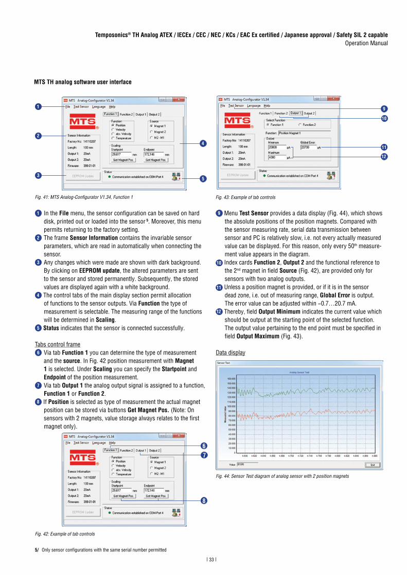
1 In the File menu, the sensor configuration can be saved on hard disk, printed out or loaded into the sensor 5. Moreover, this menu permits returning to the factory setting.
2 The frame Sensor Information contains the invariable sensor parameters, which are read in automatically when connecting the sensor.
3 Any changes which were made are shown with dark background. By clicking on EEPROM update, the altered parameters are sent to the sensor and stored permanently. Subsequently, the stored values are displayed again with a white background.
4 The control tabs of the main display section permit allocation of functions to the sensor outputs. Via Function the type of measurement is selectable. The measuring range of the functions will be determined in Scaling.
5 Status indicates that the sensor is connected successfully.
Tabs control frame6 Via tab Function 1 you can determine the type of measurement
and the source. In Fig. 42 position measurement with Magnet 1 is selected. Under Scaling you can specify the Startpoint and Endpoint of the position measurement.
7 Via tab Output 1 the analog output signal is assigned to a function, Function 1 or Function 2.
8 If Position is selected as type of measurement the actual magnet position can be stored via buttons Get Magnet Pos. (Note: On sensors with 2 magnets, value storage always relates to the first magnet only).
9 Menu Test Sensor provides a data display (Fig. 44), which shows the absolute positions of the position magnets. Compared with the sensor measuring rate, serial data transmission between sensor and PC is relatively slow, i.e. not every actually measured value can be displayed. For this reason, only every 50th measure- ment value appears in the diagram.10 Index cards Function 2, Output 2 and the functional reference to the 2nd magnet in field Source (Fig. 42), are provided only for sensors with two analog outputs.11 Unless a position magnet is provided, or if it is in the sensor dead zone, i.e. out of measuring range, Global Error is output. The error value can be adjusted within −0.7…20.7 mA.12 Thereby, field Output Minimum indicates the current value which should be output at the starting point of the selected function. The output value pertaining to the end point must be specified in field Output Maximum (Fig. 43).
Data display
5/ Only sensor configurations with the same serial number permitted
Fig. 41: MTS Analog-Configurator V1.34, Function 1
Fig. 42: Example of tab controls
Fig. 43: Example of tab controls
Fig. 44: Sensor Test diagram of analog sensor with 2 position magnets
MTS TH analog software user interface
5
2
1
4
3
11
9
10
12
6
8
7

34
Temposonics® TH Analog ATEX / IECEx / CEC / NEC / KCs / EAC Ex certified / Japanese approval / Safety SIL 2 capableOperation Manual
Fig. 45: Set start- and endpoint
5.2.4 Setting examples for programming tools
The sensor‘s measuring range can be repositioned using the toolsdescribed above within the active measuring range at any time.
NOTICE
Independent of the measuring direction, the location of the setpoints in the factory settings is always: SP1 (set point 1) at sensor electronics housing and SP2 (set point 2) at rod end (Fig. 45).
Fig. 46: Start- and endpoint, set the direction
0 %SP1
100 %SP2
100 %SP2
4 mA
20 mA
20 mA
0 %SP1
4 mA
Active measuring range
20.7 mA*
Default settingOutput: 4…20 mA
20.7 mA*
New field settingOutput: 4…20 mA
0 %SP1 Active
measuring range
Active measuring range
100 %SP2
0 %SP1
4 mA
4 mA
20 mA20.7 mA*
Default settingOutput: 4…20 mA
100 %SP2
20.7 mA*
20 mA
* default error message
* default error message
New field settingOutput: 4…20 mA
0 %SP1
100 %SP2
100 %SP2
4 mA
20 mA
20 mA
0 %SP1
4 mA
Active measuring range
20.7 mA*
Default settingOutput: 4…20 mA
20.7 mA*
New field settingOutput: 4…20 mA
0 %SP1 Active
measuring range
Active measuring range
100 %SP2
0 %SP1
4 mA
4 mA
20 mA20.7 mA*
Default settingOutput: 4…20 mA
100 %SP2
20.7 mA*
20 mA
* default error message
* default error message
New field settingOutput: 4…20 mA

35
Temposonics® TH Analog ATEX / IECEx / CEC / NEC / KCs / EAC Ex certified / Japanese approval / Safety SIL 2 capableOperation Manual
6. Maintenance and troubleshooting
6.1 Error conditions, troubleshooting
Error condition Status
Magnet error Error value at outputStandard version:Current output: 20.7 mA (default error message)SIL 2 version:Current output: < 3.6 mA (close to 0 mA)
6.2 Maintenance
The required inspections need to be performed by qualified person-nel according to IEC 60079-17 / TRBS 1203. These inspections should include at least a visual inspection of the housing, associated elec-trical equipment entrance points, retention hardware and equipment grounding. Inside the Ex-atmosphere the equipment has to be cleaned regularly. The user determines the intervals for checking according to the environmental conditions present at the place of operation. After maintenance and repair, all protective devices removed for this purpo-se must be refitted.
NOTICE
Perform maintenance work that requires a dismantling of the system only in an Ex-free atmosphere. If this is not possible take protective measures in compliance with local regulations.
Maintenance: Defines a combination of any actions carried out to re-tain an item in, or restore it to, conditions in which it is able to meet the requirements of the relevant specification and perform its required functions.
Fig. 47: Schedule of inspection
Type of inspection
Visual inspectionevery 3 months
Close inspectionevery 6 months
Detailed inspectionevery 12 months
Visual inspection of the sensor for intactness, removal ofdust deposits
Check of electrical system for intactness and functionality
Check of entire system
User’s responsibility
Inspection: Defines an activity with the purpose of checking a product carefully, aiming at a reliable statement of the condition of the product. The inspection is carried out without dismantling, or, if necessary, with partial dismantling, and supplemented by other measures, e.g. measu-rements.Visual inspection: Optical inspection of product aims at the recognition of visible defects like missing bolts without using auxiliary equipment and tools.Close inspection: Defines an inspection which encompasses those as-pects covered by a visual inspection and, in addition, identifies those defects, such as loose bolts, which will be apparent only by the use of access equipment, for example steps, where necessary, and tools.Detailed inspection: Defines an inspection which encompasses those aspects covered by a close inspection and, in addition, identifies those defects, such as loose terminations, which will only be apparent byopening the enclosure, and / or using, where necessary, tools and test equipment.
6.3 Repair
Repairs of the sensor may only be performed by MTS Sensors ora repair facility explicitly authorized by MTS Sensors. Repairs of the fla-meproof joints must be made by the manufacturer in compliance with the constructive specifications. Repairs must not be made on the basis of values specified in tables 1 and 2 of IEC/EN 60079-1.
6.4 List of spare parts
No spare parts are available for this sensor.
6.5 Transport and storage
Note the storage temperature of the sensor, which is from −40…+93 °C (−40…+199.4 °F).
7. Removal from service / dismantling
The product contains electronic components and must be disposed of in accordance with the local regulations.

36
Temposonics® TH Analog ATEX / IECEx / CEC / NEC / KCs / EAC Ex certified / Japanese approval / Safety SIL 2 capableOperation Manual
8. Technical data Temposonics® TH SIL 2
Output
Current 4…20 mA, 20…4 mA (minimum / maximum load 0 / 500 Ω)
Measured value Position
Measurement parameters
Resolution 16 bit; 0.0015 % (minimum 1 µm) 6
Cycle time 2.0 ms
Linearity 7 < ±0.01 % F.S. (minimum ±50 µm)
Repeatability < ±0.001 % F.S. (minimum ±2.5 µm) typical
Hysteresis < 4 µm typical
Temperature coefficient < 30 ppm/K typical
Operating conditions
Operating temperature Version E: −40…+80 °C (−40…+176 °F)Version D, G: −40…+85 °C (−40…+185 °F)
Humidity 90 % relative humidity, no condensation
Ingress protection Version D, G and E: IP66 / IP67 (if properly connected by means that support IP66 / IP67 (pipe, gland, etc.))Version N: IP66, IP67, IP68, IP69K, NEMA 4X, depending on cable gland
Shock test 100 g (single shock), IEC standard 60068-2-27
Vibration test 15 g / 10…2000 Hz, IEC standard 60068-2-6 (resonance frequencies excluded)
EMC test Electromagnetic emission according to IEC/EN 61326-1 (Class B)Electromagnetic immunity according to IEC/EN 61326-3-2 (Class B)The sensor meets the requirements of the EU directives and is marked with
Operating pressure 350 bar static (5076 psi static)
Magnet movement velocity 8 Any
Design / Material
Sensor electronics housing Stainless steel 1.4305 (AISI 303); option: Stainless steel 1.4404 (AISI 316L)
Flange See “Table 1: TH rod sensor threaded flange type references” on page 12
Sensor rod Stainless steel 1.4306 (AISI 304L); option: Stainless steel 1.4404 (AISI 316L)
Stroke length 25…1500 mm (1…60 in.)
Mechanical mounting
Mounting position Any orientation
Mounting instruction Please consult the technical drawings on page 11
Electrical connection
Connection type T-Series terminal
Operating voltage +24 VDC (−15 / +20 %)
Ripple ≤ 0.28 VPP
Current consumption 100 mA typical
Dielectric strength 700 VDC (DC ground to machine ground)
Polarity protection Up to −30 VDC
Overvoltage protection Up to 36 VDC
6/ The internal digital value is transferred via a 16 bit D/A converter into a proportional, analog current signal
7/ With position magnet # 201 542-2
8/ If there is contact between the moving magnet (including the magnet holder) and the sensor rod, make sure that the maximum speed of the moving magnet is ≤ 1 m/s (Safety requirement due to ESD [Electro Static Discharge])

37
Temposonics® TH Analog ATEX / IECEx / CEC / NEC / KCs / EAC Ex certified / Japanese approval / Safety SIL 2 capableOperation Manual
Certifications
Certifi cation required Version E Version D Version G Version N
IECEx / ATEX(IECEx: Global market;
ATEX: Europe)
Ex db eb IIC T4 Ga/GbEx tb IIIC T130°C Ga/DbZone 0/1, Zone 21−40 °C ≤ Ta ≤ 80 °C
Ex db IIC T4 Ga/GbEx tb IIIC T130°C Ga/DbZone 0/1, Zone 21−40 °C ≤ Ta ≤ 85 °C
Ex db IIC T4 Ga/GbEx tb IIIC T130°C Ga/DbZone 0/1, Zone 21−40 °C ≤ Ta ≤ 85 °C
No hazardous area approval
NEC(USA)
Non-incendive Class I Div. 2 Groups A, B, C, D T4Class II/III Div. 2 Groups E, F, G −40 °C ≤ Ta ≤ 80 °C Non-sparkingClass I Zone 2 AEx nA IIC T4 GcClass II/III Zone 22 AEx tc IIIC T130°C Dc−40 °C ≤ Ta ≤ 80 °C
—
ExplosionproofClass I Div. 1 Groups A, B, C, D T4Class II/III Div. 1 Groups E, F, G T130°C−40 °C ≤ Ta ≤ 85 °C
FlameproofClass I Zone 0/1 AEx d IIC T4Class II/III Zone 21 AEx tb IIIC T130°C−40 °C ≤ Ta ≤ 85 °C
No hazardous area approval
CEC(Canada)
Non-incendive Class I Div. 2 Groups A, B, C, D T4Class II/III Div. 2 Groups E, F, G −40 °C ≤ Ta ≤ 80 °C
Non-sparkingClass I Zone 2 Ex nA IIC T4 GcClass II/III Zone 22 Ex tc IIIC T130°C Dc−40 °C ≤ Ta ≤ 80 °C
—
ExplosionproofClass I Div. 1 Groups B, C, D T4Class II/III Div. 1 Groups E, F, G T130°C−40 °C ≤ Ta ≤ 85 °C
FlameproofClass I Zone 0/1 Ex d IIC T4 Ga/GbClass II/III Zone 21 Ex tb IIIC T130°C Db−40 °C ≤ Ta ≤ 85 °C
No hazardous area approval
EAC Ex(Russian market)
Ga/Gb Ex db eb IIC T4 XDa/Db Ex tb IIIC T130°C XZone 0/1, Zone 21−40 °C ≤ Ta ≤ 80 °C
Ga/Gb Ex db IIC T4 XDa/Db Ex tb IIIC T130°C XZone 0/1, Zone 21−40 °C ≤ Ta ≤ 85 °C
Ga/Gb Ex db IIC T4 XDa/Db Ex tb IIIC T130°C XZone 0/1, Zone 21−40 °C ≤ Ta ≤ 85 °C
No hazardous area approval
Japanese approval Ex d e IIC T4 Ga/GbEx t IIIC T130°C DbZone 0/1, Zone 21−40 °C ≤ Ta ≤ 80 °C
Ex d IIC T4 Ga/GbEx t IIIC T130°C DbZone 0/1, Zone 21−40 °C ≤ Ta ≤ 85 °C
Ex d IIC T4 Ga/GbEx t IIIC T130°C DbZone 0/1, Zone 21−40 °C ≤ Ta ≤ 85 °C
No hazardous area approval
KCs(Korea)
Ex d e IIC T4Ex tb IIIC T130°CZone 0/1; Zone 21 −40 °C ≤ Ta ≤ 80 °C
Ex d IIC T4Ex tb IIIC T130°CZone 0/1; Zone 21−40 °C ≤ Ta ≤ 85 °C
Ex d IIC T4Ex tb IIIC T130°CZone 0/1, Zone 21−40 °C ≤ Ta ≤ 85 °C
No hazardous area approval
Fig. 48: Certifications TH SIL 2

38
Temposonics® TH Analog ATEX / IECEx / CEC / NEC / KCs / EAC Ex certified / Japanese approval / Safety SIL 2 capableOperation Manual
Device @ 1 % accuracy
λSD λSU λDD λDU SFF
T-Series @ 60 °C
0 100 802 62 93.6 %
T-Series @ 80 °C
0 283 2266 175 93.6 %
T-Series @ 85 °C
0 400 3205 248 93.6 %
Safety values for maximum operating temperature
SIL 2 sensor parameter
T-Series (SIL 2: Analog Safety) IEC 61508
Safety Level SIL 2
Device type B
MTTFd 100 years @ 60 °C 44 years @ 80 °C
PFDavg 3.49E-04 @ 60 °C 9.85E-04 @ 80 °C
Diagnostic Response Time (Fail Detection Time)
25 ms (max) 1 sec for CRC fault detection
% of SIL 2 range for PFD 3.5 % @ 60 °C9.9 % @ 80 °C
Hardware Fault Tolerance (HFT) 0
Useful lifetime 50 years @ 60 °C 18 years @ 80 °C
Device @ 1 % accuracy(60 °C / 80 °C / 85 °C)
SFF 93.6 %
Fig. 49: Sensor parameter TH SIL 2
Fig. 50: Safety values TH SIL 2

39
Temposonics® TH Analog ATEX / IECEx / CEC / NEC / KCs / EAC Ex certified / Japanese approval / Safety SIL 2 capableOperation Manual
9. Technical data Temposonics® TH standard
Output
Current 4(0)…20 mA, 20…4(0) mA (minimum / maximum load: 0 / 500 Ω)
Measured value Position
Measurement parameters
Resolution 16 bit; 0.0015 % (minimum 1 µm) 9
Cycle time 0.5 ms up to 1200 mm stroke length1.0 ms up to 2400 mm stroke length2.0 ms up to 4800 mm stroke length5.0 ms up to 7620 mm stroke length
Linearity 10 < ±0.01 % F.S. (minimum ±50 µm)
Repeatability < ±0.001 % F.S. (minimum ±2.5 µm) typical
Hysteresis < 4 µm typical
Temperature coefficient < 30 ppm/K typical
Operating conditions
Operating temperature −40…+75 °C (−40…+167 °F)
Humidity 90 % relative humidity, no condensation
Ingress protection Version D, G, and E: IP66 / IP67 (if properly connected by means that support IP66 / IP67 (pipe, gland, etc.))Version N: IP66, IP67, IP68, IP69K, NEMA 4X, depending on cable gland
Shock test 100 g (single shock), IEC standard 60068-2-27
Vibration test 15 g / 10…2000 Hz, IEC standard 60068-2-6 (excluding resonant frequencies)
EMC test Electromagnetic emission according to IEC/EN 55011 +A1 Class BElectromagnetic immunity according to IEC/EN 61000-6-2The sensor meets the requirements of the EU directives and is marked with
Operating pressure 350 bar static (5076 psi static)
Magnet movement velocity 11 Any
Design / Material
Sensor electronics housing Stainless steel 1.4305 (AISI 303); option: Stainless steel 1.4404 (AISI 316L)
Flange See “Table 1: TH rod sensor threaded flange type references” on page 12
Sensor rod Stainless steel 1.4306 (AISI 304L); option: Stainless steel 1.4404 (AISI 316L)
Stroke length 25…7620 mm (1…300 in.)
Mechanical mounting
Mounting position Any orientation
Mounting instruction Please consult the technical drawings on page 11
Electrical connection
Connection type T-Series terminal
Operating voltage +24 VDC (−15 / +20 %)
Ripple ≤ 0.28 VPP
Current consumption 100 mA typical
Dielectric strength 700 VDC (DC ground to machine ground)
Polarity protection Up to −30 VDC
Overvoltage protection Up to 36 VDC
9/ The internal digital value is transferred via a 16 bit D/A converter into a proportional, analog current signal
10/ With position magnet # 201 542-2
11/ If there is contact between the moving magnet (including the magnet holder) and the sensor rod, make sure that the maximum speed of the moving magnet is ≤ 1 m/s (Safety requirement due to ESD [Electro Static Discharge])

40
Temposonics® TH Analog ATEX / IECEx / CEC / NEC / KCs / EAC Ex certified / Japanese approval / Safety SIL 2 capableOperation Manual
Certifications
Certifi cation required Version E Version D Version G Version N
IECEx / ATEX(IECEx: Global market;
ATEX: Europe)
Ex db eb IIC T4 Ga/GbEx tb IIIC T130°C Ga/DbZone 0/1, Zone 21−40 °C ≤ Ta ≤ 75 °C
Ex db IIC T4 Ga/GbEx tb IIIC T130°C Ga/DbZone 0/1, Zone 21−40 °C ≤ Ta ≤ 75 °C
Ex db IIC T4 Ga/GbEx tb IIIC T130°C Ga/DbZone 0/1, Zone 21−40 °C ≤ Ta ≤ 75 °C
No hazardous area approval
NEC(USA)
— —
ExplosionproofClass I Div. 1 Groups A, B, C, D T4Class II/III Div. 1 Groups E, F, G T130°C−40 °C ≤ Ta ≤ 75 °C
FlameproofClass I Zone 0/1 AEx d IIC T4Class II/III Zone 21 AEx tb IIIC T130°C−40 °C ≤ Ta ≤ 75 °C
No hazardous area approval
CEC(Canada)
— —
ExplosionproofClass I Div. 1 Groups B, C, D T4Class II/III Div. 1 Groups E, F, G T130°C−40 °C ≤ Ta ≤ 75 °C
FlameproofClass I Zone 0/1 Ex d IIC T4 Ga/GbClass II/III Zone 21 Ex tb IIIC T130°C Db−40 °C ≤ Ta ≤ 75 °C
No hazardous area approval
EAC Ex(Russian market)
Ga/Gb Ex db eb IIC T4 XDa/Db Ex tb IIIC T130°C XZone 0/1, Zone 21−40 °C ≤ Ta ≤ 75 °C
Ga/Gb Ex db IIC T4 XDa/Db Ex tb IIIC T130°C XZone 0/1, Zone 21−40 °C ≤ Ta ≤ 75 °C
Ga/Gb Ex db IIC T4 XDa/Db Ex tb IIIC T130°C XZone 0/1, Zone 21−40 °C ≤ Ta ≤ 75 °C
No hazardous area approval
Japanese approval Ex d e IIC T4 Ga/GbEx t IIIC T130°C DbZone 0/1, Zone 21−40 °C ≤ Ta ≤ 75 °C
Ex d IIC T4 Ga/GbEx t IIIC T130°C DbZone 0/1, Zone 21−40 °C ≤ Ta ≤ 75 °C
Ex d IIC T4 Ga/GbEx t IIIC T130°C DbZone 0/1, Zone 21−40 °C ≤ Ta ≤ 75 °C
No hazardous area approval
KCs(Korea)
Ex d e IIC T4Ex tb IIIC T130°CZone 0/1; Zone 21−40 °C ≤ Ta ≤ 75 °C
Ex d IIC T4Ex tb IIIC T130°CZone 0/1; Zone 21−40 °C ≤ Ta ≤ 75 °C
Ex d IIC T4Ex tb IIIC T130°CZone 0/1; Zone 21−40 °C ≤ Ta ≤ 75 °C
No hazardous area approval
Fig. 51: Certifications TH standard

41
10. Declaration of conformity of standard version
Page 1 of 1
Handelsregister: Amtsgericht Iserlohn HRA 3314 • Geschäftsführer: Dr.-Ing. Thomas Grahl, David Thomas Hore MTS Sensor Technologie ist ein Unternehmen der MTS Systems Corporation, Minneapolis, USA
EU Declaration of ConformityEU-KonformitätserklärungDéclaration UE de Conformité
MTS Sensor Technologie GmbH & Co. KG, Auf dem Schueffel 9, 58513 Luedenscheid, Germany
declares as manufacturer in sole responsibility that the position sensor typeerklärt als Hersteller in alleiniger Verantwortung, dass der Positionssensor Typdéclare en qualité de fabricant sous sa seule responsabilité que les capteurs position de type
Temposonics TH-x-xxxxx-xxx-1-D-N-N-AxxTH-x-xxxxx-xxx-1-G-N-N-AxxTH-x-xxxxx-xxx-1-E-N-N-Axx
comply with the regulations of the following European Directives:den Vorschriften folgender Europäischen Richtlinien entsprechen:sont conformes aux prescriptions des directives européennes suivantes:
2014/34/EU Equipment and protective systems for use in potentially explosive atmospheresGeräte und Schutzsysteme zur Verwendung in explosionsgefährdeten BereichenAppareils et systèmes de protection à être utilisés en atmosphères explosibles
2014/30/EU Electromagnetic CompatibilityElektromagnetische VerträglichkeitCompatibilité électromagnétique
2011/65/EU Restriction of the use of hazardous substances in electrical and electronic equipmentBeschränkung der Verwendung gefährlicher Stoffe in Elektro- und ElektronikgerätenLimitation de l’utilisation de substances dangereuses dans les équipements électriques et électroniques
Applied harmonized standards / Angewandte harmonisierte Normen / Normes harmonisées appliquées:
EN 60079-0:2012+A11:2013, EN 60079-1:2014, EN 60079-7:2015, EN 60079-26:2015, EN 60079-31:2014EN 61000-6-2:2005+AC:2005, EN 61000-6-3:2007+A1:2011+AC:2012, EN 55011:2009+A1:2010 Class B
EC type examination certificate:EG-Baumusterprüfbescheinigung: CML ATEX 1090 XCertificat de l’examen CE:issued by / ausgestellt durch / exposé par: Certification Management Limited
Ellesmere Port CH65 4LZ, United Kingdom (2503)
Notified body for quality assurance control: Certification Management LimitedBenannte Stelle für Qualitätsüberwachung: Ellesmere Port CH65 4LZ, United KingdomOrganisme notifié pour l’assurance qualité:Ident number / Kennnummer / Numéro d’identification: 2503
Marking / Kennzeichnung / Marquage: e II 1/2G Ex db IIC T4 Ga/Gb resp.e II 1/2G Ex db eb IIC T4 Ga/Gb resp.e II 1G/2D Ex tb IIIC T130°C Ga/Db
Luedenscheid, 2018-10-01
MTS Sensor Technologie GmbH & Co. KG
____________________________________Dr.-Ing. Eugen Davidoff
Approvals ManagerEx Authorized Representative
EC15.001H

42
Page 1 of 1
Handelsregister: Amtsgericht Iserlohn HRA 3314 • Geschäftsführer: Dr.-Ing. Thomas Grahl, David Thomas Hore MTS Sensor Technologie ist ein Unternehmen der MTS Systems Corporation, Minneapolis, USA
EU Declaration of ConformityEU-KonformitätserklärungDéclaration UE de Conformité
MTS Sensor Technologie GmbH & Co. KG, Auf dem Schueffel 9, 58513 Luedenscheid, Germany
declares as manufacturer in sole responsibility that the position sensor typeerklärt als Hersteller in alleiniger Verantwortung, dass der Positionssensor Typdéclare en qualité de fabricant sous sa seule responsabilité que les capteurs position de type
Temposonics TH-x-xxxxx-xxx-1-D-S-N-AxxTH-x-xxxxx-xxx-1-G-S-N-AxxTH-x-xxxxx-xxx-1-E-S-N-Axx
comply with the regulations of the following European Directives:den Vorschriften folgender Europäischen Richtlinien entsprechen:sont conformes aux prescriptions des directives européennes suivantes:
2014/34/EU Equipment and protective systems for use in potentially explosive atmospheresGeräte und Schutzsysteme zur Verwendung in explosionsgefährdeten BereichenAppareils et systèmes de protection à être utilisés en atmosphères explosibles
2014/30/EU Electromagnetic CompatibilityElektromagnetische VerträglichkeitCompatibilité électromagnétique
2011/65/EU Restriction of the use of hazardous substances in electrical and electronic equipmentBeschränkung der Verwendung gefährlicher Stoffe in Elektro- und ElektronikgerätenLimitation de l’utilisation de substances dangereuses dans les équipements électriques et électroniques
Applied harmonized standards / Angewandte harmonisierte Normen / Normes harmonisées appliquées:
EN 60079-0:2012+A11:2013, EN 60079-1:2014, EN 60079-7:2015, EN 60079-26:2015, EN 60079-31:2014EN 61326-1:2013, EN 61326-3-2:2008
EC type examination certificate:EG-Baumusterprüfbescheinigung: CML ATEX 1090 XCertificat de l’examen CE:issued by / ausgestellt durch / exposé par: Certification Management Limited
Ellesmere Port CH65 4LZ, United Kingdom (2503)
Notified body for quality assurance control: Certification Management LimitedBenannte Stelle für Qualitätsüberwachung: Ellesmere Port CH65 4LZ, United KingdomOrganisme notifié pour l’assurance qualité:Ident number / Kennnummer / Numéro d’identification: 2503
Marking / Kennzeichnung / Marquage: e II 1/2G Ex db IIC T4 Ga/Gb resp.e II 1/2G Ex db e IIC T4 Ga/Gb resp.e II 1G/2D Ex tb IIIC T130°C Ga/Db
Luedenscheid, 2017-10-04
MTS Sensor Technologie GmbH & Co. KG
____________________________________Dr.-Ing. Eugen Davidoff
Approvals ManagerEx Authorized Representative
EC15.002G
11. Declaration of conformity of SIL 2 version

43
12. Appendix
Safety Declaration
Dear Customer,If you return one or several sensors for checking or repair, we need you to sign a safety declaration. The purpose of this declaration is to ensure that the returned items do not contain residues of harmful substances and / or that people handling these items will not be in danger.
MTS Sensors order number: _______________________________
Serial number(s): ___________________________________
Sensor type(s): _________________________________________
Sensor length: _________________________________________
The sensor has been in contact with the following materials:
In the event of suspected penetration of substances into the sensor, consult MTS Sensors to determine measures to be taken before shipment.
Don’t specify chemical formulas.Please include safety data sheets of the substances, if applicable.
Short description of malfunction:
Corporate information
Company: _______________________________________________
Address: _______________________________________________
_______________________________________________
Contact partner
Name: _______________________________________________
Phone: _______________________________________________
E-Mail: _______________________________________________
We hereby certify that the measuring equipment has been cleaned and neutralized. Equipment handling is safe. Personnel exposure to health risks during transport and repair is excluded.
DateSignatureStamp
Tel. + 49 - 23 51- 95 87 0Fax. + 49 - 23 51- 5 64 [email protected]
GERMANYMTS Sensor Technologie GmbH & Co.KG Auf dem Schüffel 9 58513 Lüdenscheid, Germany
USAMTS Systems CorporationSensors Division3001 Sheldon DriveCary, N.C. 27513, USA
Tel. +1 919 677-0100Fax +1 919 [email protected]

UNITED STATESMTS Systems Corporation
Sensors Division
3001 Sheldon DriveCary, N.C. 27513Phone: +1 919 677-0100E-mail: [email protected]
GERMANYMTS Sensor Technologie
GmbH & Co. KG
Auf dem Schüffel 958513 LüdenscheidPhone: +49 2351 9587-0E-mail: [email protected]
ITALYBranch Offi ce
Phone: +39 030 988 3819E-mail: [email protected]
FRANCEBranch Offi ce
Phone: +33 1 58 4390-28E-mail: [email protected]
GREAT BRITAIN Branch Offi ce
Phone: +44 79 44 15 03 00E-mail: [email protected]
CHINABranch Offi ce
Phone: +86 21 6485 5800 E-mail: [email protected]
JAPANBranch Offi ce
Phone: +81 3 6416 1063E-mail: [email protected]
www.mtssensors.comMTS, Temposonics and Level Plus are registered trademarks of MTS Systems Corporation in the United States; MTS SENSORS and the MTS SENSORS logo are trademarks of MTS Systems Corporation within the United States. These trademarks may be protected in other countries. All other trademarks are the property of their respective owners. Copyright © 2018 MTS Systems Corporation. No license of any intellectual property rights is granted. MTS reserves the right to change the information within this document, change product designs, or withdraw products from availability for purchase without notice. Typographic and graphics errors or omissions are unintentional and subject to correction. Visit www.mtssensors.com for the latest product information.
Reg.-No. 003095-QM08
Document Part Number 551513 Revision F (EN) 10/2018