Embed Size (px)
Citation preview

TEMPORARY RESTORATIONS ON CAMLOG® AND CONELOG® IMPLANTS
TEMPORARY ABUTMENTS FOR CROWN AND BRIDGE RESTORATIONS
Titelblatt_ProvisorischesAbutment.indd 1 19.01.2016 13:59:28

1
TEMPORARY ABUTMENTS FOR CROWN AND BRIDGE RESTORATIONS
GENERAL SYSTEM INFORMATION 2
CAMLOG® AND CONELOG® TEMPORARY ABUTMENTSPRODUCT DESCRIPTION 3CAMLOG® TEMPORARY ABUTMENTS, PEEK 4CAMLOG® TEMPORARY ABUTMENTS, TITANIUM ALLOY 5CONELOG® TEMPORARY ABUTMENTS, TITANIUM ALLOY 6REQUIRED INSTRUMENTS / LAB ANALOGS / SCREWS 7
APPLICATION 8IMPRESSION TAKING AND CAST FABRICATION 8FABRICATION OF TEMPORARY RESTORATIONS 9CAMLOG® TEMPORARY ABUTMENTS, PEEK 9CAMLOG® AND CONELOG® TEMPORARY ABUTMENTS, TITANIUM ALLOY 11
ARTICLE LIST 13
MATERIAL 16
FURTHER DOCUMENTATION 17
TABLE OF CONTENTS

2
TEMPORARY ABUTMENTS FOR CROWN AND BRIDGE RESTORATIONS
GENERAL
SYSTEM INFORMATION
CAMLOG® AND CONELOG® IMPLANT SYSTEMSCAMLOG® and CONELOG® Implant systems have been developed based on long-standing clinical and laboratory experience. The two systems are user-friendly and consistently prosthetical-oriented.
All CAMLOG® and CONELOG® products are always manufactured using the most state-of-the-art technology. Both implant systems are continuously being developed by the company’s research and development team in col-laboration with clinics, universities and dental technicians and therefore stay abreast of the latest technology.
The CAMLOG® Implant System is very well-documented scientifically. Stud-ies support this with respect to a great many parameters including the im-plant surface, time of implantation and/or implant loading, primary stabil-ity, connection design or type of superstructure. The long-term results of the CAMLOG® Implant System are convincing.
IMPORTANT NOTEThe descriptions that follow are not adequate to permit immediate use of the CAMLOG® and CONELOG® Implant System. Instruction by a sur-geon experienced in using one of the two systems is strongly recom-mended. CAMLOG® and CONELOG® products should only be used by dentists, doctors, surgeons and dental technicians who have been trained in using the system. Appropriate courses and training sessions are regularly offered by CAMLOG. Methodological errors in treatment can result in loss of the implant and significant loss of peri-implant bone.
IMPORTANT NOTE• The abutments may not be modified at the implant-abutment connection.• Further important information on the CAMLOG® and CONELOG® products is described in the instruction manuals and must be observed.
COLOR-CODING OF THE SURGICAL AND PROSTHETICAL CAMLOG® AND CONELOG® PRODUCTS
COLOR DIAMETER
gray 3.3 mm
yellow 3.8 mm
red 4.3 mm
blue 5.0 mm
green 6.0 mm

3
TEMPORARY ABUTMENTS FOR CROWN AND BRIDGE RESTORATIONS
CAMLOG® Temporary abutments CONELOG® Temporary abutmentsPEEK TITANIUM ALLOY TITANIUM ALLOY
CAMLOG® AND CONELOG®
TEMPORARY ABUTMENTSPRODUCT DESCRIPTION
Various abutments are available for the CAMLOG® and the CONELOG® Im-plant systems for temporary prosthetic restorations. CAMLOG® and CONELOG® Temporary abutments made of titanium alloy (Ti6Al4V ELI) are available in crown and bridge versions.
As an option, temporary restoration on CAMLOG® Implants can also be performed with temporary abutments made of PEEK (poly ether ether ketone).
The abutments are for use as immediate restorations and, if required, can also be used for long-term temporary restorations in the maxilla and mandible. The benefits of immediate implantation with non-functional immediate res-toration consist in preservation of the structures of the periodontal or peri- implant tissue. After an adequate healing phase (osseointegration) for the implant and maturing of the peri-implant soft tissue, a new impression is taken for the final restoration.
All CAMLOG® and CONELOG® Temporary abutments are supplied with an abutment screw and can be shortened individually (extraorally). Options for fabricating a prosthetic restoration are either directly on the patient (chair-side) or on the working model in the laboratory (lab-side).
To fabricate a bridge restoration, the temporary abutments, bridge (titanium alloy) can be primarily splinted. All temporary abutments can be veneered directly with plastic.
Single crowns and secondary cementa-ble bridge frame-works (Passive-Fit)
Single crowns Single crownsBridge restorations(with CAMLOG® marking)
Bridge restorations(with CONELOG® marking)

4
TEMPORARY ABUTMENTS FOR CROWN AND BRIDGE RESTORATIONS
OPTION PLATFORM SWITCHINGThe Platform Switching option is possible with CAMLOG® Temporary abut-ments PS. To make appropriate soft-tissue management possible for plat-form switching, healing caps PS are used for healing. This requires the sub-sequent use of the temporary abutment PS for platform switching. Like the healing caps PS, these are also tapered in the apical area making it possible to adapt soft tissue over the CAMLOG® Implant shoulder.
NOTEFabrication of a temporary restoration with a CAMLOG® Temporary abutment PEEK or a CAMLOG® Temporary abutment PS PEEK is identi-cal in terms of handling.
Apical tapering
ART. NO. K2208.3800 K2208.4300 K2208.5000 K2208.6000
Implant Ø in mm 3.8 4.3 5.0 6.0Prosthetic height in mm 12.0 12.0 12.0 12.0
CAMLOG® Temporary abutment PS, with Tube-in-Tube® Implant-abutment connection, PEEK, incl. CAMLOG® Abutment screw
IMPORTANT NOTETo avoid tissue injury with temporary restorations, only temporary abut-ments PS for Platform Switching may be used in conjunction with the prior use of healing caps PS!
ART. NO. K2241.3800 K2241.4300 K2241.5000 K2241.6000
Implant Ø in mm 3.8 4.3 5.0 6.0Prosthetic height in mm 12.0 12.0 12.0 12.0
CAMLOG® TEMPORARY ABUTMENTS, PEEK
TEMPORARY RESTORATIONSCAMLOG® Temporary abutments, PEEK, are available with a Tube-in-Tube® Implant-abutment connection for positioning/as antirotational mechanism for the use of immediate restorations. They can also be used for long-term temporary restorations up to a maximum of 6 months as needed.
CAMLOG® Temporary abutment, with Tube-in-Tube® Implant-abutment connection, PEEK, incl. CAMLOG® Abutment screw
PS: Platform Switching
5
TEMPORARY ABUTMENTS FOR CROWN AND BRIDGE RESTORATIONS
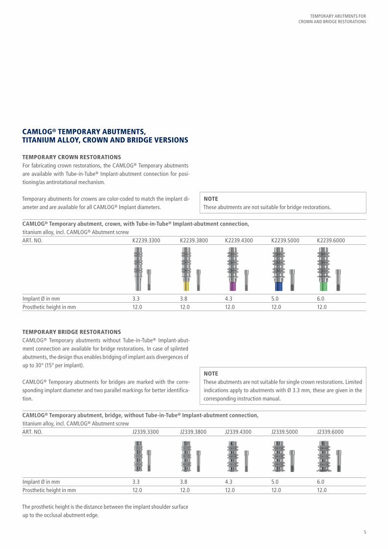
CAMLOG® TEMPORARY ABUTMENTS, TITANIUM ALLOY, CROWN AND BRIDGE VERSIONS
TEMPORARY CROWN RESTORATIONSFor fabricating crown restorations, the CAMLOG® Temporary abutments are available with Tube-in-Tube® Implant-abutment connection for posi-tioning/as antirotational mechanism.
Temporary abutments for crowns are color-coded to match the implant di-ameter and are available for all CAMLOG® Implant diameters.
TEMPORARY BRIDGE RESTORATIONSCAMLOG® Temporary abutments without Tube-in-Tube® Implant-abut-ment connection are available for bridge restorations. In case of splinted abutments, the design thus enables bridging of implant axis divergences of up to 30° (15° per implant).
CAMLOG® Temporary abutments for bridges are marked with the corre-sponding implant diameter and two parallel markings for better identifica-tion.
The prosthetic height is the distance between the implant shoulder surface up to the occlusal abutment edge.
CAMLOG® Temporary abutment, crown, with Tube-in-Tube® Implant-abutment connection, titanium alloy, incl. CAMLOG® Abutment screwART. NO. K2239.3300 K2239.3800 K2239.4300 K2239.5000 K2239.6000
Implant Ø in mm 3.3 3.8 4.3 5.0 6.0Prosthetic height in mm 12.0 12.0 12.0 12.0 12.0
CAMLOG® Temporary abutment, bridge, without Tube-in-Tube® Implant-abutment connection, titanium alloy, incl. CAMLOG® Abutment screwART. NO. J2339.3300 J2339.3800 J2339.4300 J2339.5000 J2339.6000
Implant Ø in mm 3.3 3.8 4.3 5.0 6.0Prosthetic height in mm 12.0 12.0 12.0 12.0 12.0
NOTEThese abutments are not suitable for bridge restorations.
NOTEThese abutments are not suitable for single crown restorations. Limited indications apply to abutments with Ø 3.3 mm, these are given in the corresponding instruction manual.
6
TEMPORARY ABUTMENTS FOR CROWN AND BRIDGE RESTORATIONS
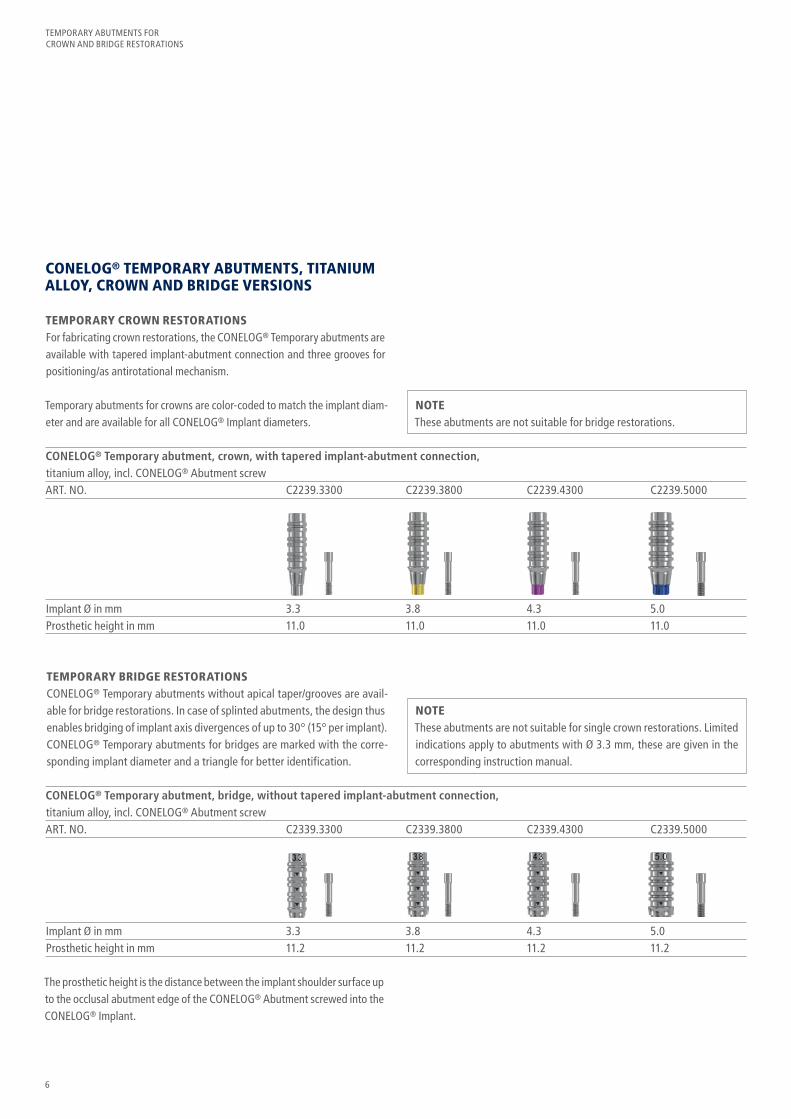
TEMPORARY BRIDGE RESTORATIONSCONELOG® Temporary abutments without apical taper/grooves are avail-able for bridge restorations. In case of splinted abutments, the design thus enables bridging of implant axis divergences of up to 30° (15° per implant). CONELOG® Temporary abutments for bridges are marked with the corre-sponding implant diameter and a triangle for better identification.
CONELOG® Temporary abutment, crown, with tapered implant-abutment connection, titanium alloy, incl. CONELOG® Abutment screwART. NO. C2239.3300 C2239.3800 C2239.4300 C2239.5000
Implant Ø in mm 3.3 3.8 4.3 5.0Prosthetic height in mm 11.0 11.0 11.0 11.0
CONELOG® TEMPORARY ABUTMENTS, TITANIUM ALLOY, CROWN AND BRIDGE VERSIONS
TEMPORARY CROWN RESTORATIONSFor fabricating crown restorations, the CONELOG® Temporary abutments are available with tapered implant-abutment connection and three grooves for positioning/as antirotational mechanism.
Temporary abutments for crowns are color-coded to match the implant diam-eter and are available for all CONELOG® Implant diameters.
NOTEThese abutments are not suitable for single crown restorations. Limited indications apply to abutments with Ø 3.3 mm, these are given in the corresponding instruction manual.
NOTEThese abutments are not suitable for bridge restorations.
CONELOG® Temporary abutment, bridge, without tapered implant-abutment connection, titanium alloy, incl. CONELOG® Abutment screwART. NO. C2339.3300 C2339.3800 C2339.4300 C2339.5000
Implant Ø in mm 3.3 3.8 4.3 5.0Prosthetic height in mm 11.2 11.2 11.2 11.2
The prosthetic height is the distance between the implant shoulder surface up to the occlusal abutment edge of the CONELOG® Abutment screwed into the CONELOG® Implant.
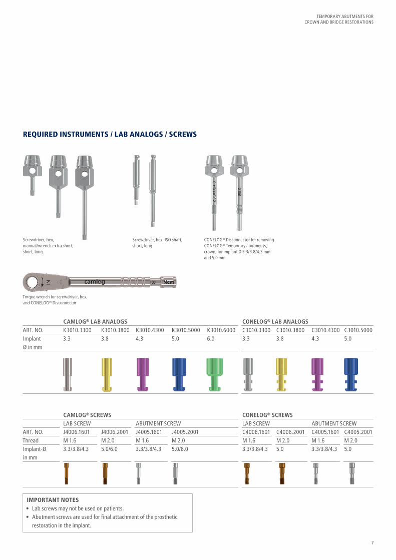
CAMLOG® SCREWS CONELOG® SCREWS LAB SCREW ABUTMENT SCREW LAB SCREW ABUTMENT SCREWART. NO. J4006.1601 J4006.2001 J4005.1601 J4005.2001 C4006.1601 C4006.2001 C4005.1601 C4005.2001Thread M 1.6 M 2.0 M 1.6 M 2.0 M 1.6 M 2.0 M 1.6 M 2.0Implant-Ø 3.3/3.8/4.3 5.0/6.0 3.3/3.8/4.3 5.0/6.0 3.3/3.8/4.3 5.0 3.3/3.8/4.3 5.0 in mm
IMPORTANT NOTES• Lab screws may not be used on patients.• Abutment screws are used for final attachment of the prosthetic restoration in the implant.
7
TEMPORARY ABUTMENTS FOR CROWN AND BRIDGE RESTORATIONS
REQUIRED INSTRUMENTS / LAB ANALOGS / SCREWS
Screwdriver, hex, ISO shaft, short, long
CONELOG® Disconnector for removing CONELOG® Temporary abutments, crown, for implant Ø 3.3/3.8/4.3 mm and 5.0 mm
Screwdriver, hex, manual/wrench extra short, short, long
CAMLOG® LAB ANALOGS CONELOG® LAB ANALOGSART. NO. K3010.3300 K3010.3800 K3010.4300 K3010.5000 K3010.6000 C3010.3300 C3010.3800 C3010.4300 C3010.5000Implant 3.3 3.8 4.3 5.0 6.0 3.3 3.8 4.3 5.0 Ø in mm
Torque wrench for screwdriver, hex, and CONELOG® Disconnector
8
TEMPORARY ABUTMENTS FOR CROWN AND BRIDGE RESTORATIONS
APPLICATION
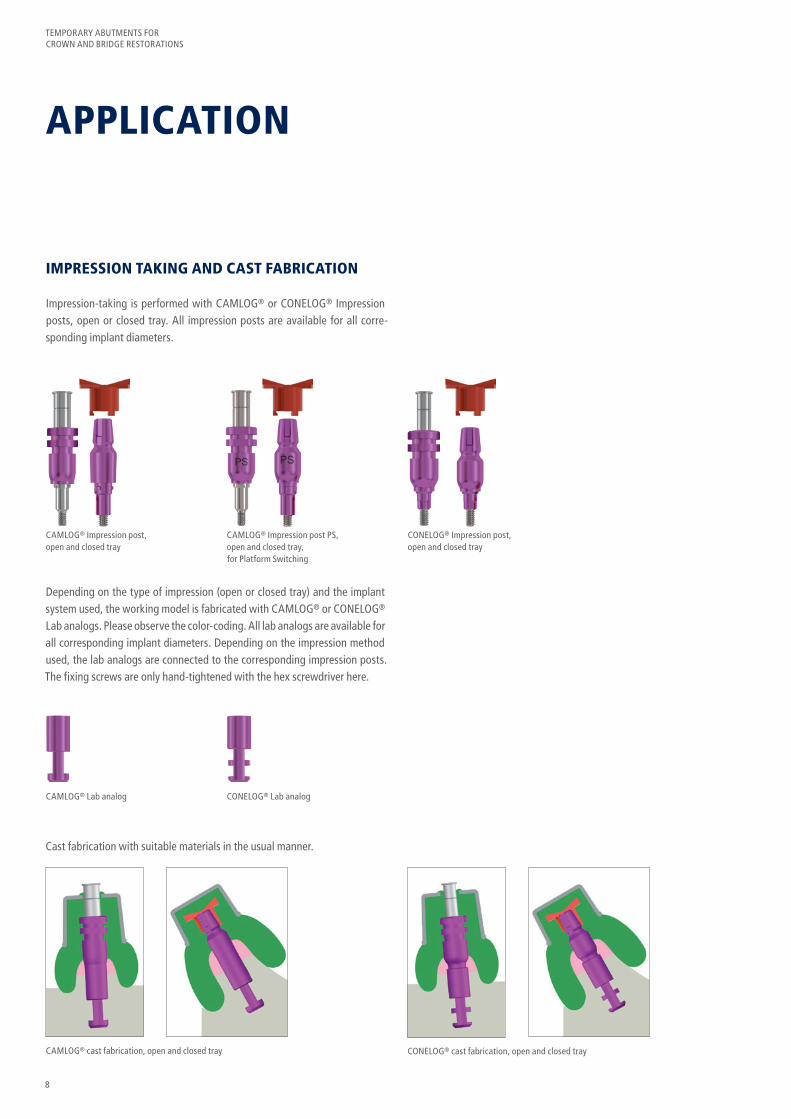
IMPRESSION TAKING AND CAST FABRICATION
Impression-taking is performed with CAMLOG® or CONELOG® Impression posts, open or closed tray. All impression posts are available for all corre-sponding implant diameters.
Depending on the type of impression (open or closed tray) and the implant system used, the working model is fabricated with CAMLOG® or CONELOG® Lab analogs. Please observe the color-coding. All lab analogs are available for all corresponding implant diameters. Depending on the impression method used, the lab analogs are connected to the corresponding impression posts. The fixing screws are only hand-tightened with the hex screwdriver here.
Cast fabrication with suitable materials in the usual manner.
CAMLOG® Impression post, open and closed tray
CAMLOG® Lab analog
CAMLOG® cast fabrication, open and closed tray CONELOG® cast fabrication, open and closed tray
CONELOG® Lab analog
CAMLOG® Impression post PS, open and closed tray, for Platform Switching
CONELOG® Impression post, open and closed tray
9
TEMPORARY ABUTMENTS FOR CROWN AND BRIDGE RESTORATIONS
FABRICATION OF TEMPORARY RESTORATIONS
CAMLOG® TEMPORARY ABUTMENTS, PEEK
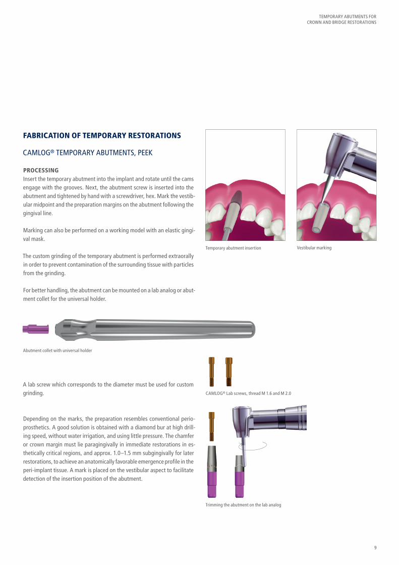
PROCESSINGInsert the temporary abutment into the implant and rotate until the cams engage with the grooves. Next, the abutment screw is inserted into the abutment and tightened by hand with a screwdriver, hex. Mark the vestib-ular midpoint and the preparation margins on the abutment following the gingival line.
Marking can also be performed on a working model with an elastic gingi-val mask.
The custom grinding of the temporary abutment is performed extraorally in order to prevent contamination of the surrounding tissue with particles from the grinding.
For better handling, the abutment can be mounted on a lab analog or abut-ment collet for the universal holder.
A lab screw which corresponds to the diameter must be used for custom grinding.
Depending on the marks, the preparation resembles conventional perio-prosthetics. A good solution is obtained with a diamond bur at high drill-ing speed, without water irrigation, and using little pressure. The chamfer or crown margin must lie paragingivally in immediate restorations in es-thetically critical regions, and approx. 1.0–1.5 mm subgingivally for later restorations, to achieve an anatomically favorable emergence profile in the peri-implant tissue. A mark is placed on the vestibular aspect to facilitate detection of the insertion position of the abutment.
Temporary abutment insertion
CAMLOG® Lab screws, thread M 1.6 and M 2.0
Trimming the abutment on the lab analog
Abutment collet with universal holder
Vestibular marking
10
TEMPORARY ABUTMENTS FOR CROWN AND BRIDGE RESTORATIONS
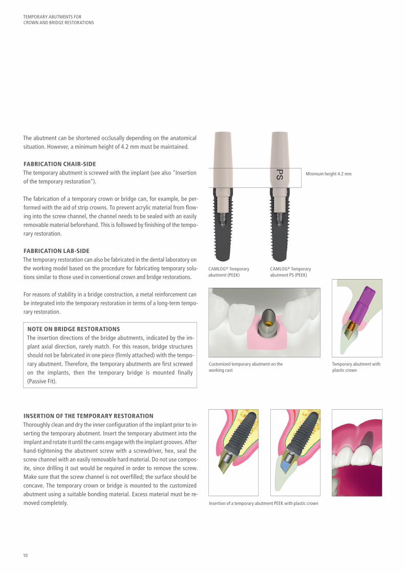
The abutment can be shortened occlusally depending on the anatomical situation. However, a minimum height of 4.2 mm must be maintained.
FABRICATION CHAIR-SIDEThe temporary abutment is screwed with the implant (see also "Insertion of the temporary restoration").
The fabrication of a temporary crown or bridge can, for example, be per-formed with the aid of strip crowns. To prevent acrylic material from flow-ing into the screw channel, the channel needs to be sealed with an easily removable material beforehand. This is followed by finishing of the tempo-rary restoration.
FABRICATION LAB-SIDEThe temporary restoration can also be fabricated in the dental laboratory on the working model based on the procedure for fabricating temporary solu-tions similar to those used in conventional crown and bridge restorations.
For reasons of stability in a bridge construction, a metal reinforcement can be integrated into the temporary restoration in terms of a long-term tempo-rary restoration.
NOTE ON BRIDGE RESTORATIONSThe insertion directions of the bridge abutments, indicated by the im-plant axial direction, rarely match. For this reason, bridge structures should not be fabricated in one piece (firmly attached) with the tempo-rary abutment. Therefore, the temporary abutments are first screwed on the implants, then the temporary bridge is mounted finally (Passive Fit).
Minimum height 4.2 mm
CAMLOG® Temporary abutment (PEEK)
Customized temporary abutment on the working cast
Temporary abutment with plastic crown
CAMLOG® Temporary abutment PS (PEEK)
INSERTION OF THE TEMPORARY RESTORATIONThoroughly clean and dry the inner configuration of the implant prior to in-serting the temporary abutment. Insert the temporary abutment into the implant and rotate it until the cams engage with the implant grooves. After hand-tightening the abutment screw with a screwdriver, hex, seal the screw channel with an easily removable hard material. Do not use compos-ite, since drilling it out would be required in order to remove the screw. Make sure that the screw channel is not overfilled; the surface should be concave. The temporary crown or bridge is mounted to the customized abutment using a suitable bonding material. Excess material must be re-moved completely. Insertion of a temporary abutment PEEK with plastic crown
11
TEMPORARY ABUTMENTS FOR CROWN AND BRIDGE RESTORATIONS
CAMLOG® AND CONELOG® TEMPORARY ABUTMENTS, TITANIUM ALLOY, CROWN AND BRIDGE VERSIONS
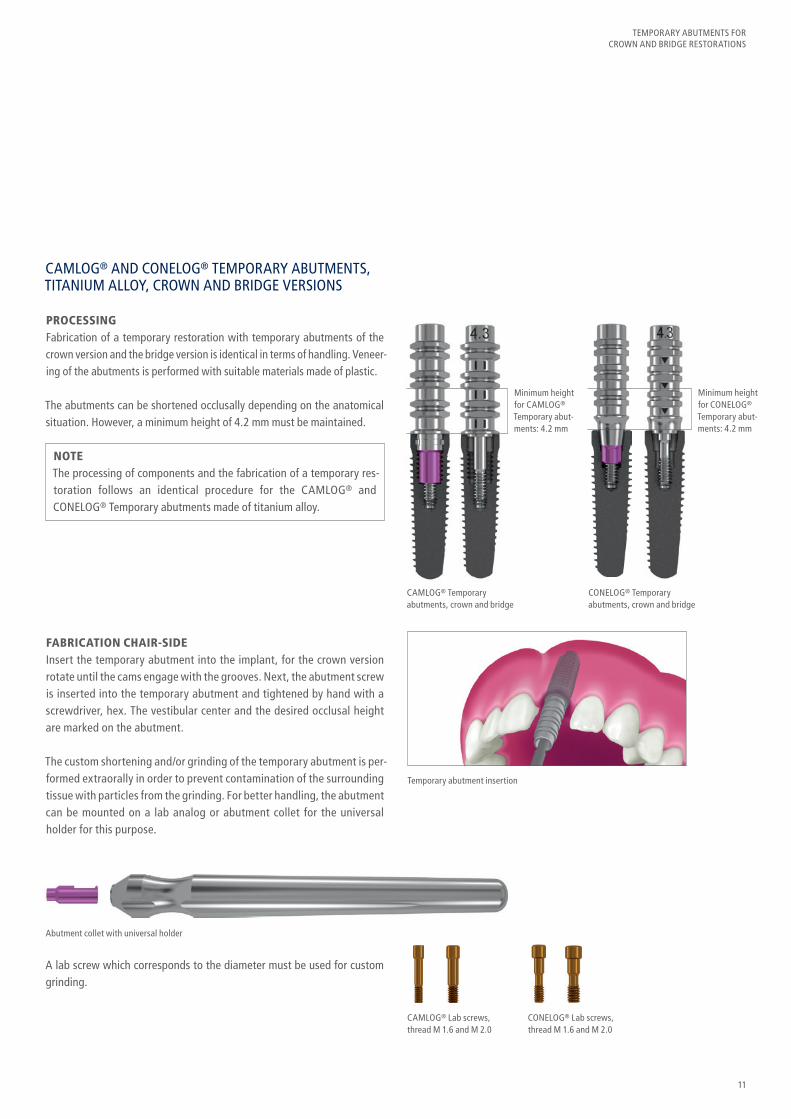
PROCESSINGFabrication of a temporary restoration with temporary abutments of the crown version and the bridge version is identical in terms of handling. Veneer-ing of the abutments is performed with suitable materials made of plastic.
The abutments can be shortened occlusally depending on the anatomical situation. However, a minimum height of 4.2 mm must be maintained.
Minimum height for CAMLOG® Temporary abut-ments: 4.2 mm
Minimum height for CONELOG® Temporary abut-ments: 4.2 mm
CAMLOG® Temporary abutments, crown and bridge
CONELOG® Temporary abutments, crown and bridge
NOTEThe processing of components and the fabrication of a temporary res-toration follows an identical procedure for the CAMLOG® and CONELOG® Temporary abutments made of titanium alloy.
FABRICATION CHAIR-SIDEInsert the temporary abutment into the implant, for the crown version rotate until the cams engage with the grooves. Next, the abutment screw is inserted into the temporary abutment and tightened by hand with a screwdriver, hex. The vestibular center and the desired occlusal height are marked on the abutment.
The custom shortening and/or grinding of the temporary abutment is per-formed extraorally in order to prevent contamination of the surrounding tissue with particles from the grinding. For better handling, the abutment can be mounted on a lab analog or abutment collet for the universal holder for this purpose.
Temporary abutment insertion
Abutment collet with universal holder
CAMLOG® Lab screws, thread M 1.6 and M 2.0
CONELOG® Lab screws, thread M 1.6 and M 2.0
A lab screw which corresponds to the diameter must be used for custom grinding.

12
TEMPORARY ABUTMENTS FOR CROWN AND BRIDGE RESTORATIONS
OPTIONALFor fixation of the long-term temporary restoration, the tightening torque is 20 Ncm after a successful healing phase of the implant. Retighten with the same torque after approx. 5 minutes to reach the maximum screw tension. These values apply to all temporary abut-ments made of titanium alloy.
After customizing and covering with opaque, the temporary abutment is inserted into the implant and screw-retained with an abutment screw. The fabrication of a temporary crown or bridge can, for example, be per-formed with the aid of strip crowns. To prevent acrylic material from flow-ing into the screw channel, the channel needs to be sealed with an easily removable material beforehand.
To loosen the temporary restoration again, the screw channel of the abut-ment must be opened for the screwdriver after the plastic has hardened. The temporary restoration is then shaped and the abutment, including the abutment screw, inserted back into the implant and the screw tight-ened accordingly.
FABRICATION LAB-SIDEThe temporary restoration can also be fabricated in the dental laboratory on the working model based on the procedure for fabricating temporary solutions similar to those used in conventional crown and bridge resto-rations. For reasons of stability in a bridge construction, a metal rein-forcement can be integrated into the temporary restoration in terms of a long-term temporary restoration.
INSERTION OF TEMPORARY RESTORATIONThoroughly clean and dry the inner configuration of the implant prior to inserting the temporary abutment. Insert the temporary abutment into the implant, for the crown version rotate until the cams engage with the grooves. After tightening the abutment screw manually with a screw-driver, hex, the screw head is sealed with an easily removable material (e.g. gutta-percha). The screw canal must be sealed for esthetic and hy-gienic reasons with a removable material (e.g. composite).
Customized temporary abutment on the working cast
Insertion of a temporary single-tooth restoration veneered directly with plastic
13
TEMPORARY ABUTMENTS FOR CROWN AND BRIDGE RESTORATIONS
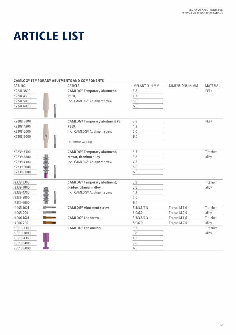
CAMLOG® TEMPORARY ABUTMENTS AND COMPONENTSART. NO. ARTICLE IMPLANT Ø IN MM DIMENSIONS IN MM MATERIAL
ARTICLE LIST
3.84.35.06.0
3.84.35.06.0
3.33.84.35.06.0
3.33.84.35.06.03.3/3.8/4.35.0/6.03.3/3.8/4.35.0/6.03.33.84.35.06.0
Thread M 1.6Thread M 2.0 Thread M 1.6Thread M 2.0
PEEK
PEEK
Titanium alloy
Titanium alloy
Titanium alloy Titanium alloy Titanium alloy
CAMLOG® Temporary abutment, PEEK,incl. CAMLOG® Abutment screw
CAMLOG® Temporary abutment PS, PEEK,incl. CAMLOG® Abutment screw
PS: Platform Switching
CAMLOG® Temporary abutment, crown, titanium alloyincl. CAMLOG® Abutment screw
CAMLOG® Temporary abutment, bridge, titanium alloyincl. CAMLOG® Abutment screw
CAMLOG® Abutment screw
CAMLOG® Lab screw
CAMLOG® Lab analog
K2241.3800K2241.4300K2241.5000K2241.6000
K2208.3800K2208.4300K2208.5000K2208.6000
K2239.3300K2239.3800K2239.4300K2239.5000K2239.6000
J2339.3300J2339.3800J2339.4300J2339.5000J2339.6000J4005.1601J4005.2001J4006.1601J4006.2001K3010.3300K3010.3800K3010.4300K3010.5000K3010.6000

14
TEMPORARY ABUTMENTS FOR CROWN AND BRIDGE RESTORATIONS
CONELOG® TEMPORARY ABUTMENTS AND COMPONENTSART. NO. ARTICLE IMPLANT Ø IN MM DIMENSIONS IN MM MATERIAL
3.33.84.35.0 3.33.84.35.0 3.3/3.8/4.35.0 3.3/3.8/4.35.0 3.33.84.35.0
Thread M 1.6Thread M 2.0Thread M 1.6Thread M 2.0
Titanium alloy
Titanium alloy
Titanium alloyTitanium alloyTitanium alloy
CONELOG® Temporary abutment, crown, titanium alloyincl. CONELOG® Abutment screw
CONELOG® Temporary abutment, bridge, titanium alloyincl. CONELOG® Abutment screw
CONELOG® Abutment screw
CONELOG® Lab screw
CONELOG® Lab analog
C2239.3300C2239.3800C2239.4300C2239.5000
C2339.3300C2339.3800C2339.4300C2339.5000C4005.1601C4005.2001C4006.1601C4006.2001C3010.3300C3010.3800C3010.4300C3010.5000
15
TEMPORARY ABUTMENTS FOR CROWN AND BRIDGE RESTORATIONS
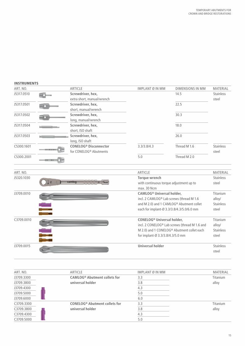
INSTRUMENTSART. NO. ARTICLE IMPLANT Ø IN MM DIMENSIONS IN MM MATERIAL
ART. NO. ARTICLE IMPLANT Ø IN MM MATERIAL
ART. NO. ARTICLE MATERIAL
Torque wrenchwith continuous torque adjustment up to max. 30 NcmCAMLOG® Universal holder,incl. 2 CAMLOG® Lab screws (thread M 1.6 and M 2.0) and 1 CAMLOG® Abutment collet each for implant-Ø 3.3/3.8/4.3/5.0/6.0 mm
CONELOG® Universal holder,incl. 2 CONELOG® Lab screws (thread M 1.6 and M 2.0) and 1 CONELOG® Abutment collet each for implant-Ø 3.3/3.8/4.3/5.0 mm
Universal holder
3.3/3.8/4.3
5.0
3.33.84.35.06.03.33.84.35.0
14.5
22.5
30.3
18.0
26.0
Thread M 1.6
Thread M 2.0
Stainless steel
Stainless steel
Titanium alloy
Titanium alloy
Stainless steel
Titanium alloy/ Stainless steel
Titanium alloy/Stainless steel
Stainless steel
J5317.0510
J5317.0501
J5317.0502
J5317.0504
J5317.0503
C5300.1601
C5300.2001
J3709.3300J3709.3800J3709.4300J3709.5000J3709.6000C3709.3300C3709.3800C3709.4300C3709.5000
J5320.1030
J3709.0010
C3709.0010
J3709.0015
Screwdriver, hex, extra short, manual/wrenchScrewdriver, hex, short, manual/wrenchScrewdriver, hex, long, manual/wrenchScrewdriver, hex, short, ISO shaftScrewdriver, hex, long, ISO shaftCONELOG® Disconnector for CONELOG® Abutments
CAMLOG® Abutment collets for universal holder
CONELOG® Abutment collets for universal holder
16
TEMPORARY ABUTMENTS FOR CROWN AND BRIDGE RESTORATIONS
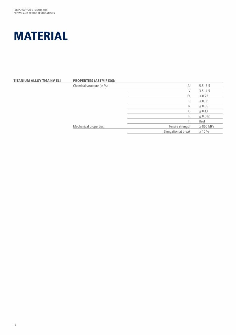
MATERIAL
TITANIUM ALLOY Ti6AI4V ELI PROPERTIES (ASTM F136): Chemical structure (in %): AI 5.5–6.5 V 3.5–4.5 Fe ≤ 0.25 C ≤ 0.08 N ≤ 0.05 O ≤ 0.13 H ≤ 0.012 Ti Rest Mechanical properties: Tensile strength ≥ 860 MPa Elongation at break ≥ 10 %
17
TEMPORARY ABUTMENTS FOR CROWN AND BRIDGE RESTORATIONS
FURTHER DOCUMENTATION
Further information on the products is available in the following documentations:
• CAMLOG® and CONELOG® Product catalog• Work instructions• Instruction manuals• Preparation instructions
The documents are available from the local CAMLOG representative. See also:http://ifu.camlog.comwww.camlog.com
TRADEMARKS AND COPYRIGHT Protected trade names (trademarks) are not specially indicated. The ab-sence of such indication does not mean that it is not a trademarked name. The publication including all its parts is protected by copyright. Any exploitation beyond the narrow limits of the copyright act is not permissi-ble without the approval of CAMLOG Biotechnologies AG and is subject to legal sanctions.

HEADQUARTERSCAMLOG Biotechnologies AG | Margarethenstrasse 38 | CH-4053 Basel Phone +41 61 565 41 00 | Fax +41 61 565 41 01 | [email protected] | www.camlog.com
Manufacturer of CAMLOG®/CONELOG® Products: ALTATEC GmbH, Maybachstraße 5, D-71299 Wimsheim
+E21
9J80
0002
031E
+$00
0006
9101
EP
Art
. No.
J800
0.02
03 R
ev. 0
01/
2016