Embed Size (px)
Citation preview

2009 Chevrolet Aveo | Aveo, Wave, G3, Barina (VIN S/T) Service Manual | Engine | Engine Controls and Fuel - 1.2L | Specifications | Document ID: 1591851
Temperature Versus Resistance
°C °F ECT Ohms IAT Ohms
Temperature vs Resistance Values (Approximate)
100 212 177 187
90 194 241 246
80 176 332 327
70 158 467 441
60 140 667 603
50 122 973 837
45 113 1188 991
40 104 1459 1180
35 95 1802 1412
30 86 2238 1700
25 77 2796 2055
20 68 3520 2500
15 59 4450 3055
10 50 5670 3760
5 41 7280 4651
0 32 9420 5800
-5 23 12300 7273
-10 14 16180 9200
-15 5 21450 9200
-20 -4 28680 15080
-30 -22 52700 25600
-40 -40 100700 45300
© 2010 General Motors Corporation. All rights reserved.
Page 1 of 1Document ID: 1591851
7/6/2010http://localhost:9001/si/showDoc.do?docSyskey=1591851&pubCellSyskey=123972&pubO...
2009 Chevrolet Aveo | Aveo, Wave, G3, Barina (VIN S/T) Service Manual | Engine | Engine Controls and Fuel - 1.2L | Specifications | Document ID: 839729
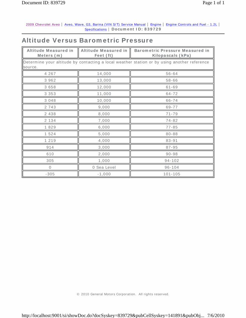
Altitude Versus Barometric Pressure
Altitude Measured in Meters (m)
Altitude Measured in Feet (ft)
Barometric Pressure Measured in Kilopascals (kPa)
Determine your altitude by contacting a local weather station or by using another reference source.
4 267 14,000 56-64
3 962 13,000 58-66
3 658 12,000 61-69
3 353 11,000 64-72
3 048 10,000 66-74
2 743 9,000 69-77
2 438 8,000 71-79
2 134 7,000 74-82
1 829 6,000 77-85
1 524 5,000 80-88
1 219 4,000 83-91
914 3,000 87-95
610 2,000 90-98
305 1,000 94-102
0 0 Sea Level 96-104
-305 -1,000 101-105
© 2010 General Motors Corporation. All rights reserved.
Page 1 of 1Document ID: 839729
7/6/2010http://localhost:9001/si/showDoc.do?docSyskey=839729&pubCellSyskey=141891&pubObj...

2009 Chevrolet Aveo | Aveo, Wave, G3, Barina (VIN S/T) Service Manual | Engine | Engine Controls and Fuel - 1.2L | Specifications | Document ID: 2038770
Ignition System Specifications
Application
Specification
Metric English
Ignition Sequence 1-3-4-2 1-3-4-2
Ignition Timing 4°- 5° (BTDC)
Ignition Type Direct Ignition System
Spark Plug Gap 0.8-0.9 mm 0.031-0.035 in
Spark Plug Maker Selim Tech
Spark Plug Type RA7YC
© 2010 General Motors Corporation. All rights reserved.
Page 1 of 1Document ID: 2038770
7/6/2010http://localhost:9001/si/showDoc.do?docSyskey=2038770&pubCellSyskey=123973&pubO...

2009 Chevrolet Aveo | Aveo, Wave, G3, Barina (VIN S/T) Service Manual | Engine | Engine Controls and Fuel - 1.2L | Specifications | Document ID: 2089328
Fastener Tightening Specifications
Application
Specifications
Metric English
Accessory Mounting Bracket Bolts 37 N·m 27 lb ft
Camshaft Position Sensor Bolt 12 N·m 106 lb in
Crankshaft Position (CKP) Sensor Bolt 6.5 N·m 58 lb in
Engine Control Module (ECM) Nuts 7 N·m 62 lb in
Engine Coolant Temperature Sensor 17.5 N·m 13 lb ft
Evaporative Emission Canister Bracket Retaining Bolt 8 N·m 71 lb in
Evaporative Emission Canister Flange Bolt 20 N·m 16 lb ft
Evaporative Emission Canister Purge Solenoid Bracket Bolt 5 N·m 44 lb in
Evaporative Emission Vent Solenoid Bolt 8.5 N·m 75 lb in
Exhaust Gas Recirculation Retaining Bolts 30 N·m 22 lb ft
Exhaust Gas Recirculation Retaining Bolts 22 N·m 16 lb ft
Exhaust Gas Recirculation Retaining Nuts 10 N·m 89 lb in
Fuel Filter Bracket Bolt 4 N·m 35 lb in
Fuel Pressure Regulator Retaining Screw 12 N·m 106 lb in
Fuel Pump Retaining Bolts 4 N·m 35 lb in
Fuel Tank Retaining Bolts 20 N·m 15 lb ft
Fuel Rail Bolt 25 N·m 18 lb ft
Heated Oxygen Sensor (HO2S) 42 N·m 31 lb ft
Idle Air Control Valve Retaining Bolts 3 N·m 27 lb in
Ignition Coil Bolt 10 N·m 89 lb in
Knock Sensor (KS) Bolt 20 N·m 15 lb ft
Map Sensor Retaining Bolts 10 N·m 89 lb in
Oil Pressure Switch Fitting 30 N·m 22 lb ft
Spark Plug Cover Bolts 3 N·m 27 lb in
Throttle Body Nuts 10.5 N·m 93 lb in
Throttle Position Sensor Retaining Bolts 3 N·m 24 lb in
© 2010 General Motors Corporation. All rights reserved.
Page 1 of 1Document ID: 2089328
7/6/2010http://localhost:9001/si/showDoc.do?docSyskey=2089328&pubCellSyskey=123974&pubO...

2009 Chevrolet Aveo | Aveo, Wave, G3, Barina (VIN S/T) Service Manual | Engine | Engine Controls and Fuel - 1.2L | Repair Instructions | Document ID: 2042877
Engine Control Module Replacement
Removal Procedure
Warning: Refer to Battery Disconnect Warning in the Preface section.
1. Disconnect the negative battery cable. 2. Pull the ECM connector lever. 3. Disconnect the ECM connector (1).
© 2010 General Motors Corporation. All rights reserved.
Page 1 of 3Document ID: 2042877
7/6/2010http://localhost:9001/si/showDoc.do?docSyskey=2042877&pubCellSyskey=124114&pubO...

4. Remove the ECM bracket retaining nuts (2). 5. Remove the ECM (1).
Installation Procedure
1. Install the ECM (1).
Caution: Refer to Fastener Caution in the Preface section.
2. Install the ECM bracket retaining nuts (2) and tighten to 7 N·m (62 lb in).
3. Connect the ECM connector (1). 4. Push the ECM connector lever.
Page 2 of 3Document ID: 2042877
7/6/2010http://localhost:9001/si/showDoc.do?docSyskey=2042877&pubCellSyskey=124114&pubO...
5. Connect the negative battery cable.
Page 3 of 3Document ID: 2042877
7/6/2010http://localhost:9001/si/showDoc.do?docSyskey=2042877&pubCellSyskey=124114&pubO...
2009 Chevrolet Aveo | Aveo, Wave, G3, Barina (VIN S/T) Service Manual | Engine | Engine Controls and Fuel - 1.2L | Repair Instructions | Document ID: 2092666
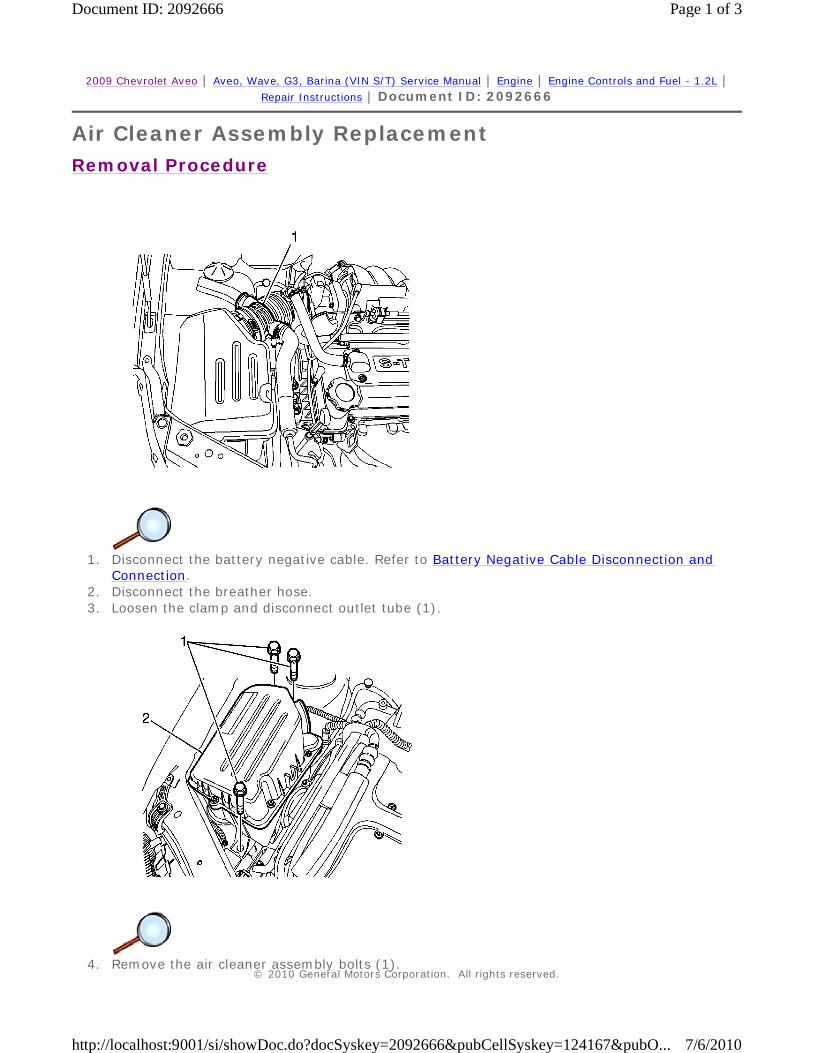
Air Cleaner Assembly Replacement
Removal Procedure
1. Disconnect the battery negative cable. Refer to Battery Negative Cable Disconnection and
Connection. 2. Disconnect the breather hose. 3. Loosen the clamp and disconnect outlet tube (1).
4. Remove the air cleaner assembly bolts (1).
© 2010 General Motors Corporation. All rights reserved.
Page 1 of 3Document ID: 2092666
7/6/2010http://localhost:9001/si/showDoc.do?docSyskey=2092666&pubCellSyskey=124167&pubO...

5. Remove the air cleaner assembly (2).
Installation Procedure
1. Install the air cleaner assembly (2).
Caution: Refer to Fastener Caution in the Preface section.
2. Install the air cleaner assembly bolts (1) and tighten to 6 N·m (4.4 lb ft).
3. Connect the air cleaner outlet tube (1) and tighten the clamp. 4. Connect the breather hose. 5. Connect the battery negative cable. Refer to Battery Negative Cable Disconnection and
Page 2 of 3Document ID: 2092666
7/6/2010http://localhost:9001/si/showDoc.do?docSyskey=2092666&pubCellSyskey=124167&pubO...

Connection.
Page 3 of 3Document ID: 2092666
7/6/2010http://localhost:9001/si/showDoc.do?docSyskey=2092666&pubCellSyskey=124167&pubO...

2009 Chevrolet Aveo | Aveo, Wave, G3, Barina (VIN S/T) Service Manual | Engine | Engine Controls and Fuel - 1.2L | Repair Instructions | Document ID: 2042852
Throttle Position Sensor Replacement
Removal Procedure
Warning: Refer to Battery Disconnect Warning in the Preface section.
1. Disconnect the battery negative cable. Refer to Battery Negative Cable Disconnection and Connection.
2. Remove the air cleaner assembly. Refer to Air Cleaner Assembly Replacement 3. Disconnect the throttle position sensor (TPS) connector
4. Remove the TPS retaining bolts (1). 5. Remove the TPS (2).
Installation Procedure
© 2010 General Motors Corporation. All rights reserved.
Page 1 of 2Document ID: 2042852
7/6/2010http://localhost:9001/si/showDoc.do?docSyskey=2042852&pubCellSyskey=124122&pubO...

1. Install the TPS (2).
Caution: Refer to Fastener Caution in the Preface section.
2. Install the TPS retaining bolts (1) and tighten to 2.7 N·m (23.9 lb in). 3. Connect the TPS connector. 4. Install the air cleaner assembly. Refer to Air Cleaner Assembly Replacement 5. Connect the battery negative cable. Refer to Battery Negative Cable Disconnection and
Connection.
Page 2 of 2Document ID: 2042852
7/6/2010http://localhost:9001/si/showDoc.do?docSyskey=2042852&pubCellSyskey=124122&pubO...

2009 Chevrolet Aveo | Aveo, Wave, G3, Barina (VIN S/T) Service Manual | Engine | Engine Controls and Fuel - 1.2L | Repair Instructions | Document ID: 2042850
Engine Coolant Temperature Sensor Replacement
Removal Procedure
Note: Use care when handling the ECT sensor. Damage to the sensor will affect the proper operation of the fuel injection system.
1. Relieve the coolant system pressure and remove the coolant. Refer to Cooling System Draining and Filling
Warning: Refer to Battery Disconnect Warning in the Preface section.
2. Disconnect the battery negative cable. Refer to Battery Negative Cable Disconnection and Connection.
3. Disconnect the engine coolant temperature (ECT) sensor connector (1). 4. Carefully remove the ECT sensor (2).
Installation Procedure
Caution: Refer to Fastener Caution in the Preface section.
© 2010 General Motors Corporation. All rights reserved.
Page 1 of 2Document ID: 2042850
7/6/2010http://localhost:9001/si/showDoc.do?docSyskey=2042850&pubCellSyskey=124115&pubO...

1. Install the ECT sensor (2) and tighten to 17.5 N·m (12.9 lb ft). 2. Connect the engine coolant temperature (ECT) sensor connector (1). 3. Connect the battery negative cable. Refer to Battery Negative Cable Disconnection and
Connection. 4. Fill the cooling system. Refer to Cooling System Draining and Filling.
Page 2 of 2Document ID: 2042850
7/6/2010http://localhost:9001/si/showDoc.do?docSyskey=2042850&pubCellSyskey=124115&pubO...

2009 Chevrolet Aveo | Aveo, Wave, G3, Barina (VIN S/T) Service Manual | Engine | Engine Controls and Fuel - 1.2L | Repair Instructions | Document ID: 2042861
Manifold Absolute Pressure Sensor Replacement
Removal Procedure
Warning: Refer to Battery Disconnect Warning in the Preface section.
1. Disconnect the negative battery cable. 2. Disconnect the T-MAP sensor connector. 3. Remove the T-MAP sensor retaining bolt. 4. Remove the T-MAP sensor (1).
Installation Procedure
© 2010 General Motors Corporation. All rights reserved.
Page 1 of 2Document ID: 2042861
7/6/2010http://localhost:9001/si/showDoc.do?docSyskey=2042861&pubCellSyskey=124118&pubO...

1. Install the T-MAP sensor (1).
Caution: Refer to Fastener Caution in the Preface section.
2. Install the T-MAP sensor retaining bolt and tighten to 10 N·m (89 lb in). 3. Connect the T-MAP sensor connector. 4. Connect the negative battery cable.
Page 2 of 2Document ID: 2042861
7/6/2010http://localhost:9001/si/showDoc.do?docSyskey=2042861&pubCellSyskey=124118&pubO...

2009 Chevrolet Aveo | Aveo, Wave, G3, Barina (VIN S/T) Service Manual | Engine | Engine Controls and Fuel - 1.2L | Repair Instructions | Document ID: 2042858
Heated Oxygen Sensor Replacement - Sensor 1
Special Tools
EN-48259 Oxygen Sensor Remover/Installer
Removal Procedure
Warning: Refer to Battery Disconnect Warning in the Preface section.
1. Disconnect the battery negative cable. Refer to Battery Negative Cable Disconnection and
Connection.
Caution: Refer to Heated Oxygen and Oxygen Sensor Caution in the Preface section.
2. Disconnect the front heated oxygen sensor (HO2S1) connector.
Caution: Refer to Heated Oxygen and Oxygen Sensor Caution in the Preface section.
3. Carefully remove the HO2S1 (1) by using EN-48259 from the exhaust manifold.
Installation Procedure
© 2010 General Motors Corporation. All rights reserved.
Page 1 of 2Document ID: 2042858
7/6/2010http://localhost:9001/si/showDoc.do?docSyskey=2042858&pubCellSyskey=124119&pubO...

Note: A special anti-seize compound is used on the oxygen sensor threads. This compound consists of a liquid graphite and glass beads. The graphite will burn away, but the glass beads will remain, making the sensor easier to remove. New or service sensors will already have the compound applied to the threads. If a sensor is removed from any engine and if for any reason it is to be reinstalled, the threads must have anti-seize compound applied before reinstallation.
1. Coat the threads of the HO2S1 with an anti-seize compound, if needed.
Caution: Refer to Fastener Caution in the Preface section.
2. Install the HO2S1 (1) into the exhaust manifold and tighten to 42 N·m (31 lb ft). 3. Connect the HO2S1 connector. 4. Connect the battery negative cable. Refer to Battery Negative Cable Disconnection and
Connection.
Page 2 of 2Document ID: 2042858
7/6/2010http://localhost:9001/si/showDoc.do?docSyskey=2042858&pubCellSyskey=124119&pubO...

2009 Chevrolet Aveo | Aveo, Wave, G3, Barina (VIN S/T) Service Manual | Engine | Engine Controls and Fuel - 1.2L | Repair Instructions | Document ID: 2042860
Heated Oxygen Sensor Replacement - Sensor 2
Special Tools
EN-48259 Oxygen Sensor Remover/Installer
Removal Procedure
Warning: Refer to Battery Disconnect Warning in the Preface section.
1. Disconnect the battery negative cable. Refer to Battery Negative Cable Disconnection and
Connection.
Caution: Refer to Heated Oxygen and Oxygen Sensor Caution in the Preface section.
2. Disconnect the electrical connector.
Caution: Refer to Heated Oxygen and Oxygen Sensor Caution in the Preface section.
3. Carefully remove the HO2S2 (1) by using the EN-48259 .
Installation Procedure
© 2010 General Motors Corporation. All rights reserved.
Page 1 of 2Document ID: 2042860
7/6/2010http://localhost:9001/si/showDoc.do?docSyskey=2042860&pubCellSyskey=124120&pubO...

Note: A special anti-seize compound is used on the oxygen sensor threads. This compound consists of a liquid graphite and glass beads. The graphite will burn away, but the glass beads will remain, making the sensor easier to remove. New or service sensors will already have the compound applied to the threads. If a sensor is removed from any engine and if for any reason it is to be reinstalled, the threads must have anti-seize compound applied before reinstallation.
1. Coat the threads of the HO2S2 with an anti-seize compound, if needed.
Caution: Refer to Fastener Caution in the Preface section.
2. Install the HO2S2 (1) into the exhaust front pipe and tighten the oxygen sensor to 42 N·m (31 lb ft).
3. Connect the HO2S2 connector. 4. Connect the battery negative cable. Refer to Battery Negative Cable Disconnection and
Connection.
Page 2 of 2Document ID: 2042860
7/6/2010http://localhost:9001/si/showDoc.do?docSyskey=2042860&pubCellSyskey=124120&pubO...
2009 Chevrolet Aveo | Aveo, Wave, G3, Barina (VIN S/T) Service Manual | Engine | Engine Controls and Fuel - 1.2L | Repair Instructions | Document ID: 2042867
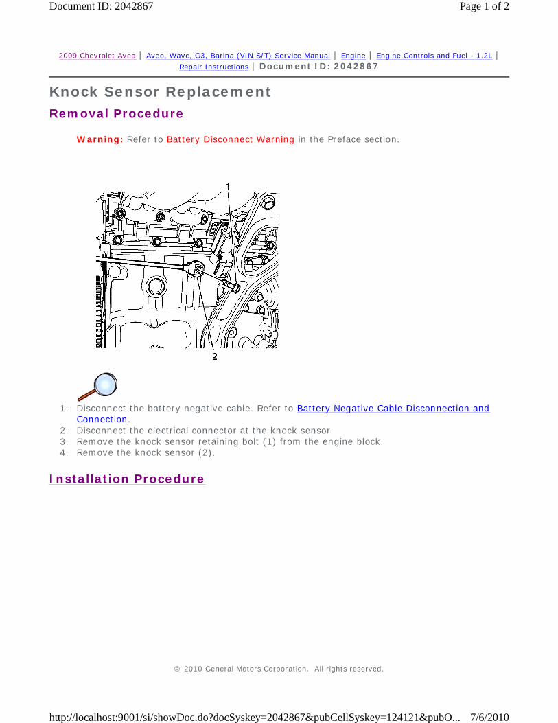
Knock Sensor Replacement
Removal Procedure
Warning: Refer to Battery Disconnect Warning in the Preface section.
1. Disconnect the battery negative cable. Refer to Battery Negative Cable Disconnection and
Connection. 2. Disconnect the electrical connector at the knock sensor. 3. Remove the knock sensor retaining bolt (1) from the engine block. 4. Remove the knock sensor (2).
Installation Procedure
© 2010 General Motors Corporation. All rights reserved.
Page 1 of 2Document ID: 2042867
7/6/2010http://localhost:9001/si/showDoc.do?docSyskey=2042867&pubCellSyskey=124121&pubO...

1. Install the knock sensor (2).
Caution: Refer to Fastener Caution in the Preface section.
2. Install the knock sensor retaining bolt (1) and tighten to 20 N·m (15 lb ft). 3. Connect the electrical connector at the knock sensor. 4. Connect the battery negative cable. Refer to Battery Negative Cable Disconnection and
Connection.
Page 2 of 2Document ID: 2042867
7/6/2010http://localhost:9001/si/showDoc.do?docSyskey=2042867&pubCellSyskey=124121&pubO...

2009 Chevrolet Aveo | Aveo, Wave, G3, Barina (VIN S/T) Service Manual | Engine | Engine Controls and Fuel - 1.2L | Repair Instructions | Document ID: 2042857
Throttle Body Assembly Replacement
Removal Procedure
Warning: Refer to Battery Disconnect Warning in the Preface section.
1. Disconnect the battery negative cable. Refer to Battery Negative Cable Disconnection and
Connection. 2. Remove the air cleaner assembly. Refer to Air Cleaner Assembly Replacement 3. Disconnect the throttle cable (2). 4. Disconnect the throttle position sensor (TPS) and IACV connectors (1). 5. Disconnect the coolant inlet and outlet hose.
© 2010 General Motors Corporation. All rights reserved.
Page 1 of 3Document ID: 2042857
7/6/2010http://localhost:9001/si/showDoc.do?docSyskey=2042857&pubCellSyskey=124128&pubO...

Note: Cover the entrance of the intake manifold after removing the throttle body to prevent any dirt from entering.
6. Remove the throttle body retaining bolts (3) and nuts (1). 7. Remove the throttle body (2) with the gasket.
Installation Procedure
1. Install the throttle body (2) with the NEW throttle body gasket.
Caution: Refer to Fastener Caution in the Preface section.
2. Install the throttle body retaining bolts (3) and nuts (1) and tighten to 10.5 N·m (7.7 lb ft).
Page 2 of 3Document ID: 2042857
7/6/2010http://localhost:9001/si/showDoc.do?docSyskey=2042857&pubCellSyskey=124128&pubO...
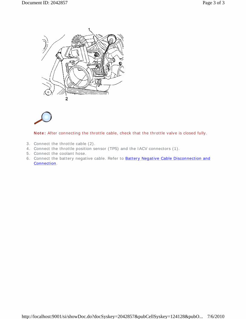
Note: After connecting the throttle cable, check that the throttle valve is closed fully.
3. Connect the throttle cable (2). 4. Connect the throttle position sensor (TPS) and the IACV connectors (1). 5. Connect the coolant hose. 6. Connect the battery negative cable. Refer to Battery Negative Cable Disconnection and
Connection.
Page 3 of 3Document ID: 2042857
7/6/2010http://localhost:9001/si/showDoc.do?docSyskey=2042857&pubCellSyskey=124128&pubO...
2009 Chevrolet Aveo | Aveo, Wave, G3, Barina (VIN S/T) Service Manual | Engine | Engine Controls and Fuel - 1.2L | Repair Instructions | Document ID: 2042854
Idle Air Control Valve Replacement
Removal Procedure
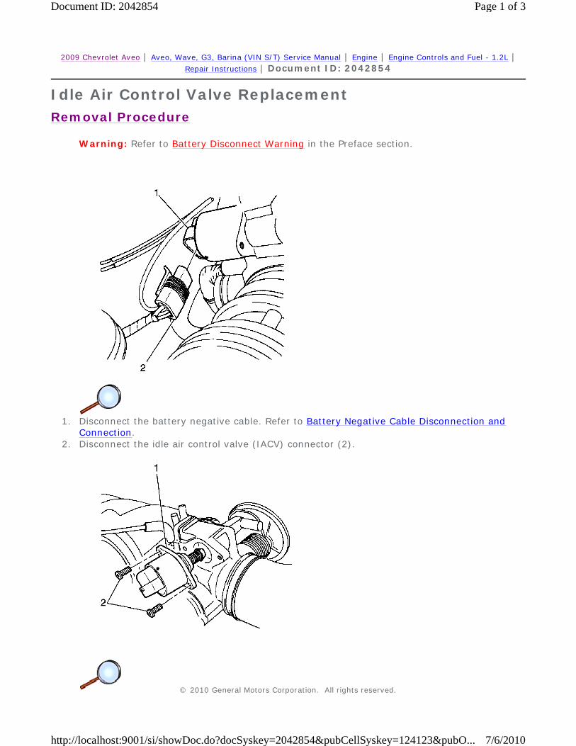
Warning: Refer to Battery Disconnect Warning in the Preface section.
1. Disconnect the battery negative cable. Refer to Battery Negative Cable Disconnection and
Connection. 2. Disconnect the idle air control valve (IACV) connector (2).
© 2010 General Motors Corporation. All rights reserved.
Page 1 of 3Document ID: 2042854
7/6/2010http://localhost:9001/si/showDoc.do?docSyskey=2042854&pubCellSyskey=124123&pubO...

Note: Clean the IAC valve O-ring seal area, the pintle valve seat and the air passage with a suitable fuel system cleaner. Do not use methyl ethyl ketone.
3. Remove the IACV retaining bolts (2). 4. Remove the IACV (1).
Installation Procedure
Note: If installing a new IAC valve, be sure to replace it with an identical part. On IACV that have been in service, do not push on the valve pintle. The force required to move the pintle may damage the threads on the worm drive.
1. Install the new O-ring seal with the IACV (1).
Caution: Refer to Fastener Caution in the Preface section.
2. Install the IACV retaining bolts (2) and tighten to 3 N·m (27 lb in).
Page 2 of 3Document ID: 2042854
7/6/2010http://localhost:9001/si/showDoc.do?docSyskey=2042854&pubCellSyskey=124123&pubO...
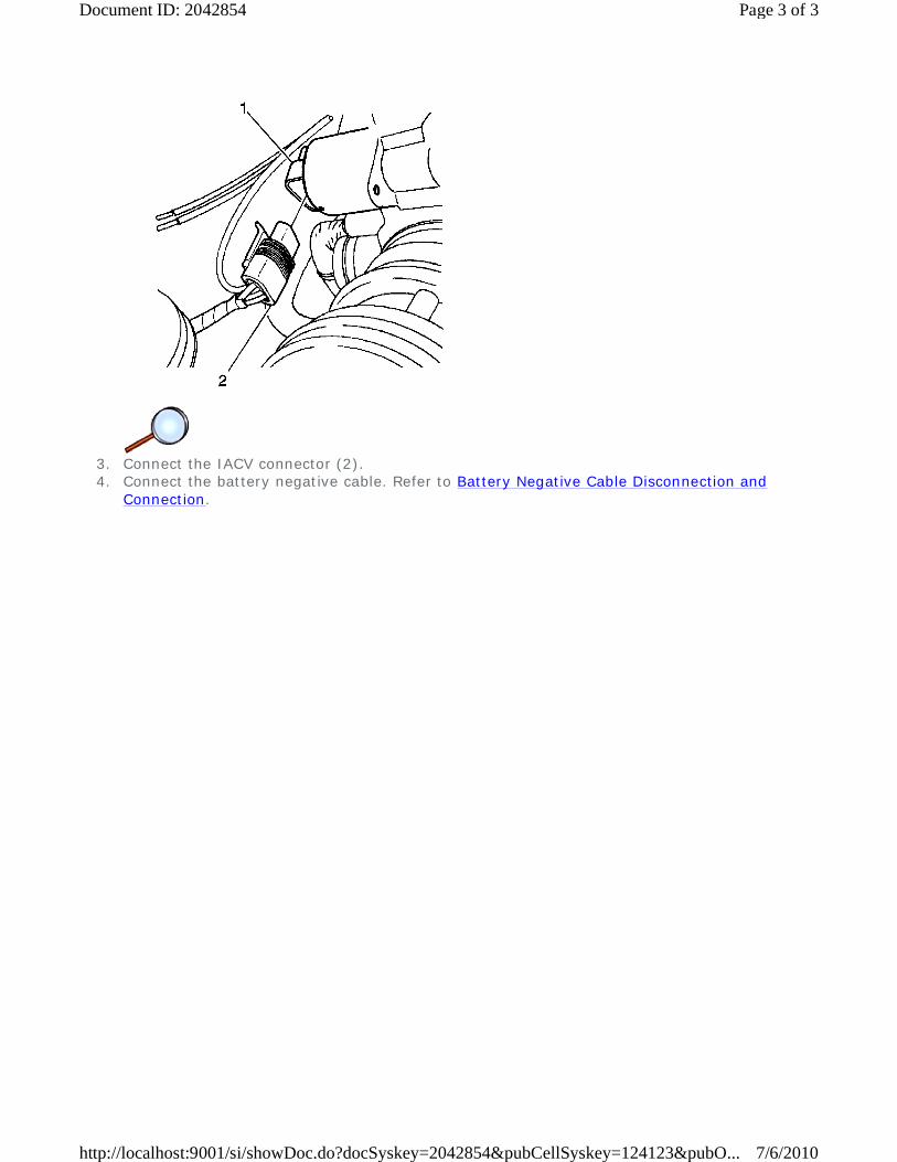
3. Connect the IACV connector (2). 4. Connect the battery negative cable. Refer to Battery Negative Cable Disconnection and
Connection.
Page 3 of 3Document ID: 2042854
7/6/2010http://localhost:9001/si/showDoc.do?docSyskey=2042854&pubCellSyskey=124123&pubO...

2009 Chevrolet Aveo | Aveo, Wave, G3, Barina (VIN S/T) Service Manual | Engine | Engine Controls and Fuel - 1.2L | Repair Instructions | Document ID: 2092555
Fuel Pressure Relief Caution: Refer to Fuel Pressure Caution in the Preface section.
1. Remove the fuel cap. 2. Remove the fuel pump fuse (1) from the engine fuse block. 3. Start the engine and allow the engine to stall. 4. Crank the engine for an additional 10 seconds.
© 2010 General Motors Corporation. All rights reserved.
Page 1 of 1Document ID: 2092555
7/6/2010http://localhost:9001/si/showDoc.do?docSyskey=2092555&pubCellSyskey=124130&pubO...

2009 Chevrolet Aveo | Aveo, Wave, G3, Barina (VIN S/T) Service Manual | Engine | Engine Controls and Fuel - 1.2L | Repair Instructions | Document ID: 2042844
Fuel Pressure Gage Installation and Removal
Special Tools
DW100-010 Fuel Pressure Gage
Caution: Refer to Fuel Pressure Caution in the Preface section.
1. Relieve the fuel pressure. Refer to Fuel Pressure Relief. 2. Remove the air cleaner assembly. Refer to Air Cleaner Assembly Replacement 3. Install the DW100-010 . 4. Measure the fuel pressure.
Fuel Pressure Specification 380 kPa (battery voltage: 13.2V)
© 2010 General Motors Corporation. All rights reserved.
Page 1 of 1Document ID: 2042844
7/6/2010http://localhost:9001/si/showDoc.do?docSyskey=2042844&pubCellSyskey=124131&pubO...

2009 Chevrolet Aveo | Aveo, Wave, G3, Barina (VIN S/T) Service Manual | Engine | Engine Controls and Fuel - 1.2L | Repair Instructions | Document ID: 2092598
Fuel Filter Replacement
Removal Procedure
Caution: Refer to Fuel Pressure Caution in the Preface section.
1. Relieve the fuel pressure. Refer to Fuel Pressure Relief.
Warning: Refer to Battery Disconnect Warning in the Preface section.
2. Disconnect the battery negative cable. Refer to Battery Negative Cable Disconnection and Connection.
3. Disconnect the inlet/outlet fuel lines by moving the line connector lock forward and pulling the hose off of the fuel filter tube.
4. Remove the fuel filter bracket bolts (1). 5. Remove the fuel filter (2).
Installation Procedure
© 2010 General Motors Corporation. All rights reserved.
Page 1 of 2Document ID: 2092598
7/6/2010http://localhost:9001/si/showDoc.do?docSyskey=2092598&pubCellSyskey=124133&pubO...

1. Install the fuel filter (2). 2. Install the fuel filter bracket bolts (1). 3. Connect the inlet/outlet quick connector lines. 4. Connect the battery negative cable. Refer to Battery Negative Cable Disconnection and
Connection.
Page 2 of 2Document ID: 2092598
7/6/2010http://localhost:9001/si/showDoc.do?docSyskey=2092598&pubCellSyskey=124133&pubO...

2009 Chevrolet Aveo | Aveo, Wave, G3, Barina (VIN S/T) Service Manual | Engine | Engine Controls and Fuel - 1.2L | Repair Instructions | Document ID: 2051915
Fuel Tank Draining Warning: Gasoline or gasoline vapors are highly flammable. A fire could occur if an ignition source is present. Never drain or store gasoline or diesel fuel in an open container, due to the possibility of fire or explosion. Have a dry chemical (Class B) fire extinguisher nearby.
1. Loosen the fuel filler cap. 2. Remove the fuel sender assembly. Refer to Fuel Sender Assembly Replacement. 3. Use a hand operated pump device in order to drain the fuel through the fuel sender assembly
opening on the fuel tank.
Note: If you are removing the fuel tank do not connect the fuel or vapor lines. Do not connect the electrical connectors or install the access panel.
4. Install the fuel sender assembly to the fuel tank. Refer to Fuel Sender Assembly Replacement.
5. Tighten the fuel filler cap.
© 2010 General Motors Corporation. All rights reserved.
Page 1 of 1Document ID: 2051915
7/6/2010http://localhost:9001/si/showDoc.do?docSyskey=2051915&pubCellSyskey=124134&pubO...

2009 Chevrolet Aveo | Aveo, Wave, G3, Barina (VIN S/T) Service Manual | Engine | Engine Controls and Fuel - 1.2L | Repair Instructions | Document ID: 2042845
Fuel Tank Replacement
Removal Procedure
Caution: Refer to Fuel Pressure Caution in the Preface section.
1. Relieve the fuel pressure. Refer to Fuel Pressure Relief.
Warning: Refer to Battery Disconnect Warning in the Preface section.
2. Disconnect the battery negative cable. Refer to Battery Negative Cable Disconnection and Connection.
3. Drain the fuel tank. 4. Disconnect the parking brake cable retainer clamps (1) and the support along the fuel tank to
provide clearance for the tank.
© 2010 General Motors Corporation. All rights reserved.
Page 1 of 4Document ID: 2042845
7/6/2010http://localhost:9001/si/showDoc.do?docSyskey=2042845&pubCellSyskey=124135&pubO...

5. Remove the fuel tank filler tube clamp at the fuel tank. 6. Disconnect the fuel tank filler tube (2). 7. Disconnect the fuel tank filler tube at the fuel tank. 8. Disconnect the canister vapor tube at control valve vapor tube (1).
9. Disconnect the fuel pump harness connector at the right rear corner of the fuel tank.
10. Disconnect the fuel inlet line (1) near the right front of the fuel tank. 11. Disconnect the wiring harness clips and the fuel line clips as needed.
Page 2 of 4Document ID: 2042845
7/6/2010http://localhost:9001/si/showDoc.do?docSyskey=2042845&pubCellSyskey=124135&pubO...

12. Support the fuel tank. 13. Remove the fuel tank retaining bolts (1). 14. Carefully lower the fuel tank (2). 15. Remove the fuel tank (2). 16. Transfer any parts as needed.
Installation Procedure
1. Raise the fuel tank (2) into position.
Caution: Refer to Fastener Caution in the Preface section.
Page 3 of 4Document ID: 2042845
7/6/2010http://localhost:9001/si/showDoc.do?docSyskey=2042845&pubCellSyskey=124135&pubO...

2. Install the fuel tank mounting bolts (1) and tighten to 20 N·m (15 lb ft).
3. Connect the fuel outlet line. 4. Connect the wiring harness clips and the fuel line clips as needed. 5. Connect the fuel pump electrical connector. 6. Connect the fuel vapor line. 7. Connect the fuel tank filler tube (2) and fuel tank vent tube (1). 8. Install the fuel tank filler tube clamp at the fuel tank.
9. Install the parking brake cable retainer clamps (1) and the support and tighten to 10 N·m
(89 lb in). 10. Connect the battery negative cable. Refer to Battery Negative Cable Disconnection and
Connection. 11. Fill the fuel tank. 12. Perform a leak check of the fuel tank and the fuel line connections.
Page 4 of 4Document ID: 2042845
7/6/2010http://localhost:9001/si/showDoc.do?docSyskey=2042845&pubCellSyskey=124135&pubO...

2009 Chevrolet Aveo | Aveo, Wave, G3, Barina (VIN S/T) Service Manual | Engine | Engine Controls and Fuel - 1.2L | Repair Instructions | Document ID: 2043566
Fuel Sender Assembly Replacement
Special Tools
EN-49090 Remover/Installer - Fuel Pump Lock Ring
Removal Procedure
Caution: Refer to Fuel Pressure Caution in the Preface section.
1. Relieve the fuel pressure.
Warning: Refer to Battery Disconnect Warning in the Preface section.
2. Disconnect the battery negative cable. Refer to Battery Negative Cable Disconnection and Connection.
3. Remove the rear seat. Refer to Rear Seat Replacement. 4. Remove the fuel pump access cover (1).
© 2010 General Motors Corporation. All rights reserved.
Page 1 of 5Document ID: 2043566
7/6/2010http://localhost:9001/si/showDoc.do?docSyskey=2043566&pubCellSyskey=124139&pubO...

5. Disconnect the electrical connectors (2) at the fuel pump assembly. 6. Disconnect the fuel outlet line (1).
7. Remove the fuel pump lock ring by using EN-49090. 8. Remove the fuel pump. 9. Disconnect the insulator.
Page 2 of 5Document ID: 2043566
7/6/2010http://localhost:9001/si/showDoc.do?docSyskey=2043566&pubCellSyskey=124139&pubO...
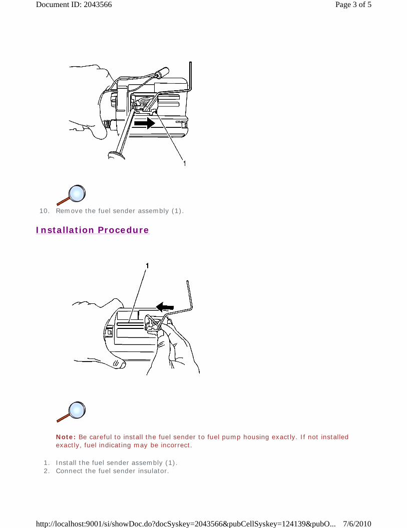
10. Remove the fuel sender assembly (1).
Installation Procedure
Note: Be careful to install the fuel sender to fuel pump housing exactly. If not installed exactly, fuel indicating may be incorrect.
1. Install the fuel sender assembly (1). 2. Connect the fuel sender insulator.
Page 3 of 5Document ID: 2043566
7/6/2010http://localhost:9001/si/showDoc.do?docSyskey=2043566&pubCellSyskey=124139&pubO...

3. Install the fuel pump to fuel tank. 4. Install the fuel pump lock ring by using EN-49090.
5. Connect the electrical connectors (2) at the fuel pump assembly. 6. Connect the fuel outlet lines (1).
Page 4 of 5Document ID: 2043566
7/6/2010http://localhost:9001/si/showDoc.do?docSyskey=2043566&pubCellSyskey=124139&pubO...

7. Install the fuel pump access cover (1). 8. Connect the battery negative cable. Refer to Battery Negative Cable Disconnection and
Connection. 9. Perform an operational check of the fuel pump.
10. Install the rear seat. Refer to Rear Seat Replacement.
Page 5 of 5Document ID: 2043566
7/6/2010http://localhost:9001/si/showDoc.do?docSyskey=2043566&pubCellSyskey=124139&pubO...

2009 Chevrolet Aveo | Aveo, Wave, G3, Barina (VIN S/T) Service Manual | Engine | Engine Controls and Fuel - 1.2L | Repair Instructions | Document ID: 2043567
Fuel Pump Replacement
Special Tools
EN-49090 Remover/Installer - Fuel Pump Lock Ring
Removal Procedure
Caution: Refer to Fuel Pressure Caution in the Preface section.
1. Relieve the fuel pressure. Refer to Fuel Pressure Relief
Warning: Refer to Battery Disconnect Warning in the Preface section.
2. Disconnect the battery negative cable. Refer to Battery Negative Cable Disconnection and Connection.
3. Remove the rear seat. Refer to Rear Seat Replacement 4. Remove the fuel pump access cover (1).
© 2010 General Motors Corporation. All rights reserved.
Page 1 of 5Document ID: 2043567
7/6/2010http://localhost:9001/si/showDoc.do?docSyskey=2043567&pubCellSyskey=124140&pubO...

5. Disconnect the electrical connectors (2) at the fuel pump assembly. 6. Disconnect the fuel outlet lines (1).
7. Remove the fuel pump lock ring by using EN-49090. 8. Remove the fuel pump. 9. Disconnect the insulator.
Page 2 of 5Document ID: 2043567
7/6/2010http://localhost:9001/si/showDoc.do?docSyskey=2043567&pubCellSyskey=124140&pubO...

10. Remove the fuel sender assembly (1).
Installation Procedure
Note: Be careful to install the fuel sender to fuel pump housing exactly. If not installed exactly, fuel indicating may be incorrect.
1. Install the fuel sender assembly (1). 2. Connect the fuel sender insulator.
Page 3 of 5Document ID: 2043567
7/6/2010http://localhost:9001/si/showDoc.do?docSyskey=2043567&pubCellSyskey=124140&pubO...
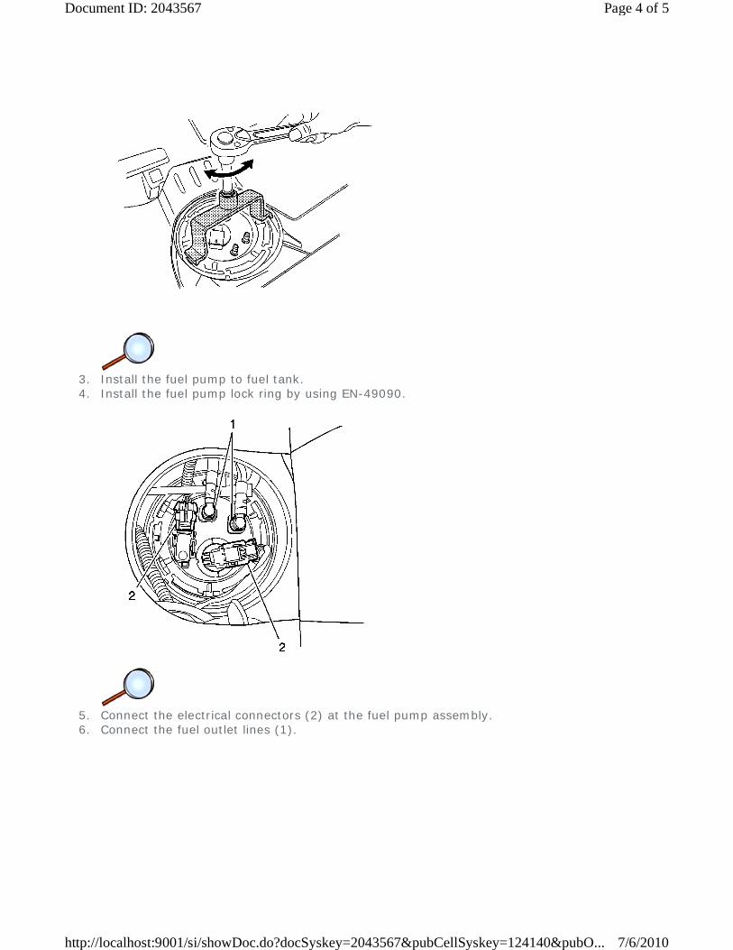
3. Install the fuel pump to fuel tank. 4. Install the fuel pump lock ring by using EN-49090.
5. Connect the electrical connectors (2) at the fuel pump assembly. 6. Connect the fuel outlet lines (1).
Page 4 of 5Document ID: 2043567
7/6/2010http://localhost:9001/si/showDoc.do?docSyskey=2043567&pubCellSyskey=124140&pubO...

7. Install the fuel pump access cover (1). 8. Connect the battery negative cable. Refer to Battery Negative Cable Disconnection and
Connection. 9. Perform an operational check of the fuel pump.
10. Install the rear seat. Refer to Rear Seat Replacement.
Page 5 of 5Document ID: 2043567
7/6/2010http://localhost:9001/si/showDoc.do?docSyskey=2043567&pubCellSyskey=124140&pubO...
2009 Chevrolet Aveo | Aveo, Wave, G3, Barina (VIN S/T) Service Manual | Engine | Engine Controls and Fuel - 1.2L | Repair Instructions | Document ID: 2042847
Fuel Injection Fuel Rail Assembly Replacement
Removal Procedure
Warning: Refer to Battery Disconnect Warning in the Preface section.
1. Disconnect the battery negative cable. Refer to Battery Negative Cable Disconnection and Connection.
Caution: Refer to Fuel Pressure Caution in the Preface section.
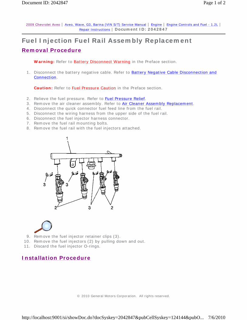
2. Relieve the fuel pressure. Refer to Fuel Pressure Relief. 3. Remove the air cleaner assembly. Refer to Air Cleaner Assembly Replacement. 4. Disconnect the quick connector fuel feed line from the fuel rail. 5. Disconnect the wiring harness from the upper side of the fuel rail. 6. Disconnect the fuel injector harness connector. 7. Remove the fuel rail mounting bolts. 8. Remove the fuel rail with the fuel injectors attached.
9. Remove the fuel injector retainer clips (3).
10. Remove the fuel injectors (2) by pulling down and out. 11. Discard the fuel injector O-rings.
Installation Procedure
© 2010 General Motors Corporation. All rights reserved.
Page 1 of 2Document ID: 2042847
7/6/2010http://localhost:9001/si/showDoc.do?docSyskey=2042847&pubCellSyskey=124144&pubO...

Note: Different injectors are calibrated for different flow rates. When ordering new fuel injectors, be certain to order the identical part number that is inscribed on the old injector.
1. Install the new O-rings on the fuel injectors (2). 2. Install the retainer clip (3) after installing injectors on the fuel rail (1). 3. Install the fuel rail and injector assembly to the intake manifold.
Caution: Refer to Fastener Caution in the Preface section.
4. Install the fuel rail retaining bolts and tighten to 10 N·m (7.3 lb ft). 5. Connect the fuel injector harness connectors. 6. Connect the harness on the upper side of the fuel rail. 7. Connect the quick connector fuel feed line on the fuel rail. 8. Install the air cleaner assembly. Refer to Air Cleaner Assembly Replacement 9. Connect the battery negative cable. Refer to Battery Negative Cable Disconnection and
Connection.
Page 2 of 2Document ID: 2042847
7/6/2010http://localhost:9001/si/showDoc.do?docSyskey=2042847&pubCellSyskey=124144&pubO...

2009 Chevrolet Aveo | Aveo, Wave, G3, Barina (VIN S/T) Service Manual | Engine | Engine Controls and Fuel - 1.2L | Repair Instructions | Document ID: 2042871
Evaporative Emission Canister Replacement
Removal Procedure
1. Remove the EVAP canister vent solenoid valve. 2. Disconnect the inlet and outlet hose from the EVAP canister. 3. Remove the EVAP canister bracket retaining bolt. 4. Remove the EVAP canister (1).
Installation Procedure
© 2010 General Motors Corporation. All rights reserved.
Page 1 of 2Document ID: 2042871
7/6/2010http://localhost:9001/si/showDoc.do?docSyskey=2042871&pubCellSyskey=124150&pubO...

1. Install the EVAP canister (1).
Caution: Refer to Fastener Caution in the Preface section.
2. Install the EVAP canister bracket retaining bolt and tighten to 8 N·m (71 lb in). 3. Connect the inlet and outlet hose to the EVAP canister. 4. Install the EVAP canister vent solenoid valve.
Page 2 of 2Document ID: 2042871
7/6/2010http://localhost:9001/si/showDoc.do?docSyskey=2042871&pubCellSyskey=124150&pubO...
2009 Chevrolet Aveo | Aveo, Wave, G3, Barina (VIN S/T) Service Manual | Engine | Engine Controls and Fuel - 1.2L | Repair Instructions | Document ID: 2042872
Evaporative Emission Canister Purge Solenoid Valve Replacement
Removal Procedure
Warning: Refer to Battery Disconnect Warning in the Preface section.
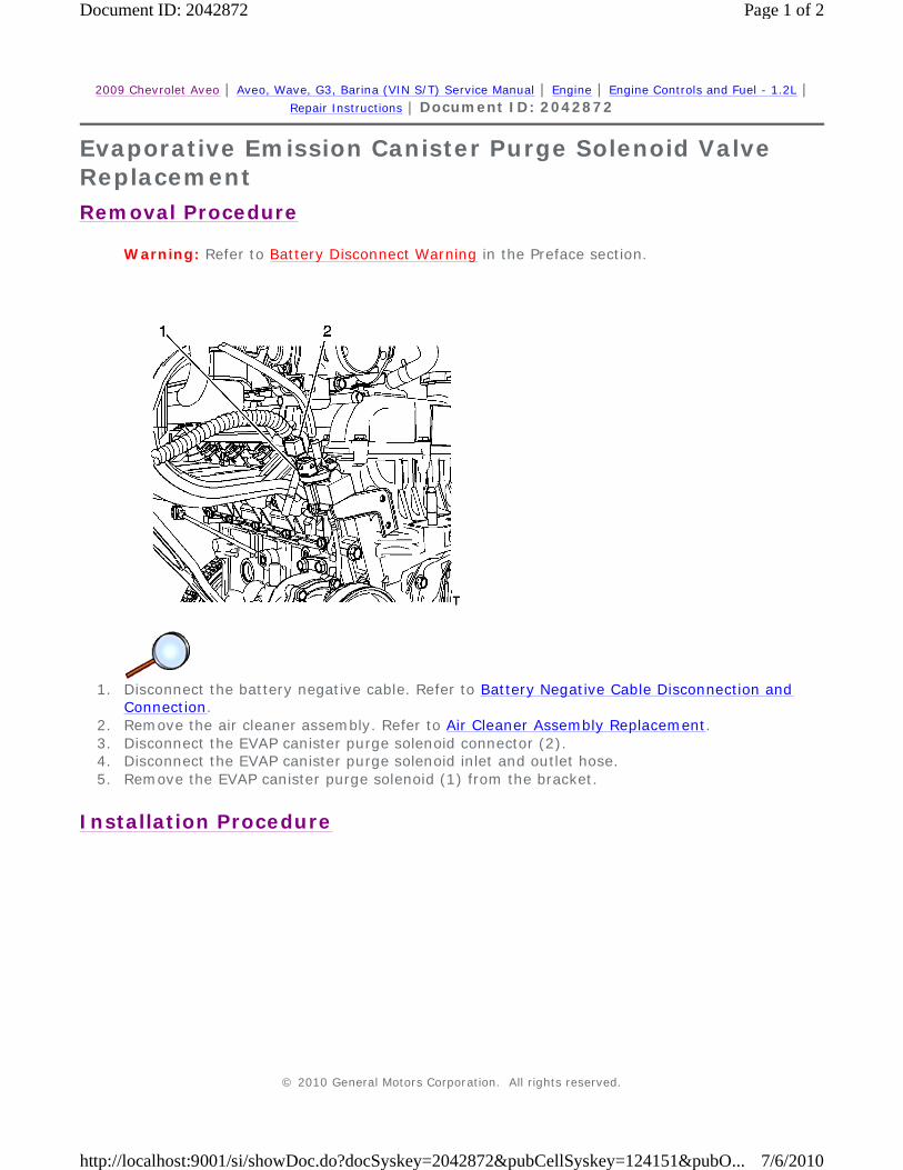
1. Disconnect the battery negative cable. Refer to Battery Negative Cable Disconnection and
Connection. 2. Remove the air cleaner assembly. Refer to Air Cleaner Assembly Replacement. 3. Disconnect the EVAP canister purge solenoid connector (2). 4. Disconnect the EVAP canister purge solenoid inlet and outlet hose. 5. Remove the EVAP canister purge solenoid (1) from the bracket.
Installation Procedure
© 2010 General Motors Corporation. All rights reserved.
Page 1 of 2Document ID: 2042872
7/6/2010http://localhost:9001/si/showDoc.do?docSyskey=2042872&pubCellSyskey=124151&pubO...

1. Install the EVAP canister purge solenoid (1) to the bracket. 2. Connect the EVAP canister purge solenoid inlet and outlet hose. 3. Connect the EVAP canister purge solenoid connector (2). 4. Install the air cleaner assembly. Refer to Air Cleaner Assembly Replacement. 5. Connect the battery negative cable. Refer to Battery Negative Cable Disconnection and
Connection.
Page 2 of 2Document ID: 2042872
7/6/2010http://localhost:9001/si/showDoc.do?docSyskey=2042872&pubCellSyskey=124151&pubO...
2009 Chevrolet Aveo | Aveo, Wave, G3, Barina (VIN S/T) Service Manual | Engine | Engine Controls and Fuel - 1.2L | Repair Instructions | Document ID: 2092652
Evaporative Emission Canister Vent Solenoid Valve Replacement
Removal Procedure
Warning: Refer to Battery Disconnect Warning in the Preface section.
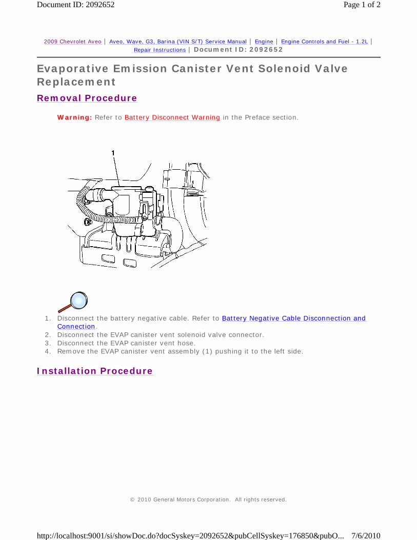
1. Disconnect the battery negative cable. Refer to Battery Negative Cable Disconnection and
Connection. 2. Disconnect the EVAP canister vent solenoid valve connector. 3. Disconnect the EVAP canister vent hose. 4. Remove the EVAP canister vent assembly (1) pushing it to the left side.
Installation Procedure
© 2010 General Motors Corporation. All rights reserved.
Page 1 of 2Document ID: 2092652
7/6/2010http://localhost:9001/si/showDoc.do?docSyskey=2092652&pubCellSyskey=176850&pubO...

1. Install the EVAP canister vent assembly (1) pushing it to the right side. 2. Connect the EVAP canister vent hose. 3. Connect the EVAP canister vent solenoid valve connector. 4. Connect the battery negative cable. Refer to Battery Negative Cable Disconnection and
Connection.
Page 2 of 2Document ID: 2092652
7/6/2010http://localhost:9001/si/showDoc.do?docSyskey=2092652&pubCellSyskey=176850&pubO...
2009 Chevrolet Aveo | Aveo, Wave, G3, Barina (VIN S/T) Service Manual | Engine | Engine Controls and Fuel - 1.2L | Repair Instructions | Document ID: 2042849
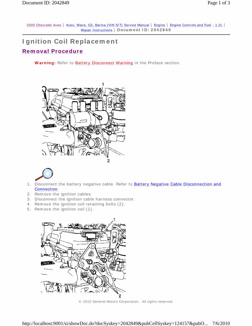
Ignition Coil Replacement
Removal Procedure
Warning: Refer to Battery Disconnect Warning in the Preface section.
1. Disconnect the battery negative cable. Refer to Battery Negative Cable Disconnection and
Connection. 2. Remove the ignition cables. 3. Disconnect the ignition cable harness connector. 4. Remove the ignition coil retaining bolts (2). 5. Remove the ignition coil (1).
© 2010 General Motors Corporation. All rights reserved.
Page 1 of 3Document ID: 2042849
7/6/2010http://localhost:9001/si/showDoc.do?docSyskey=2042849&pubCellSyskey=124157&pubO...

6. Remove the ignition coil bracket retaining bolts (2). 7. Remove the ignition coil bracket (1).
Installation Procedure
1. Install the ignition coil bracket (1).
Caution: Refer to Fastener Caution in the Preface section.
2. Install the ignition coil bracket retaining bolts (2) and tighten to 10 N·m (7.3 lb ft).
Page 2 of 3Document ID: 2042849
7/6/2010http://localhost:9001/si/showDoc.do?docSyskey=2042849&pubCellSyskey=124157&pubO...

3. Install the ignition coil (1). 4. Install the ignition coil retaining bolts (2) and tighten to 10 N·m (7.3 lb ft). 5. Connect the ignition coil harness connector. 6. Connect the ignition cables. 7. Connect the battery negative cable. Refer to Battery Negative Cable Disconnection and
Connection.
Page 3 of 3Document ID: 2042849
7/6/2010http://localhost:9001/si/showDoc.do?docSyskey=2042849&pubCellSyskey=124157&pubO...

2009 Chevrolet Aveo | Aveo, Wave, G3, Barina (VIN S/T) Service Manual | Engine | Engine Controls and Fuel - 1.2L | Repair Instructions | Document ID: 959727
Spark Plug Wire Inspection Spark plug wire integrity is vital for proper engine operation. A thorough inspection will be necessary to accurately identify conditions that may affect engine operation. Inspect for the following conditions:
1. Correct routing of the spark plug wires. Incorrect routing may cause cross-firing. 2. Any signs of cracks or splits in the wires. 3. Inspect each boot for the following conditions:
If corrosion, carbon tracking, or arcing are indicated on a spark plug wire boot or on a terminal, replace the wire and the component connected to the wire.
• Tearing
• Piercing
• Arcing
• Carbon tracking
• Corroded terminal
© 2010 General Motors Corporation. All rights reserved.
Page 1 of 1Document ID: 959727
7/6/2010http://localhost:9001/si/showDoc.do?docSyskey=959727&pubCellSyskey=124158&pubObj...

2009 Chevrolet Aveo | Aveo, Wave, G3, Barina (VIN S/T) Service Manual | Engine | Engine Controls and Fuel - 1.2L | Repair Instructions | Document ID: 1554721
Spark Plug Wire Replacement
Removal Procedure
1. Turn OFF the ignition. 2. Disconnect the spark plug wire at each spark plug.
3. Disconnect the spark plug wire from the coil.
Installation Procedure
1. Install the spark plug wire on the coil. 2. Install the spark plug wire at each spark plug. 3. Inspect the wires for proper installation:
• Twist each spark plug boot 1/2 turn before removing.
• Pull only on the boot or use a tool designed for this purpose in order to remove the wire from each spark plug.
• Twist each spark plug boot 1/2 turn before removing.
• Pull only on the boot or use a tool designed for this purpose in order to remove the wires from the coil.
• Push down on each boot in order to inspect the seating.
• Reinstall any loose boot.
• Wire routing must be kept intact during service and followed exactly when wires have been disconnected or when replacement of the wires is necessary. Failure to route the wires correctly can lead to radio interference and crossfire of the plugs, or shorting of the leads to the ground.
• Any time the spark plug wires or boots are installed on the spark plugs, new dielectric grease needs to be applied inside the boot.
© 2010 General Motors Corporation. All rights reserved.
Page 1 of 1Document ID: 1554721
7/6/2010http://localhost:9001/si/showDoc.do?docSyskey=1554721&pubCellSyskey=124159&pubO...
2009 Chevrolet Aveo | Aveo, Wave, G3, Barina (VIN S/T) Service Manual | Engine | Engine Controls and Fuel - 1.2L | Repair Instructions | Document ID: 1456106
Spark Plug Inspection
Spark Plug Usage
Spark Plug Inspection
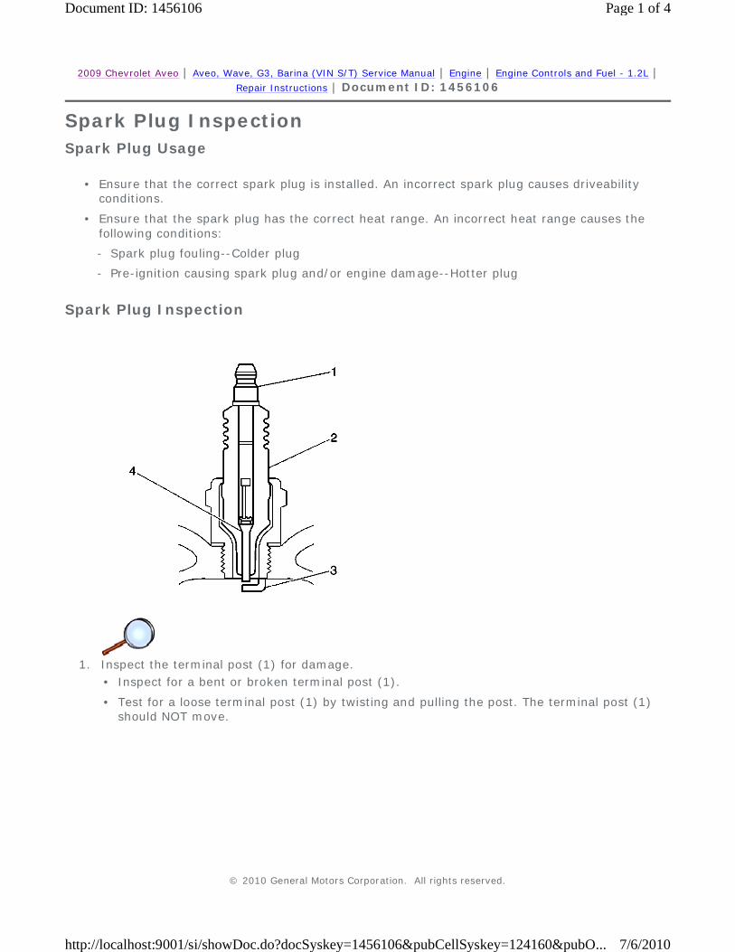
1. Inspect the terminal post (1) for damage.
• Ensure that the correct spark plug is installed. An incorrect spark plug causes driveability conditions.
• Ensure that the spark plug has the correct heat range. An incorrect heat range causes the following conditions:
- Spark plug fouling--Colder plug
- Pre-ignition causing spark plug and/or engine damage--Hotter plug
• Inspect for a bent or broken terminal post (1).
• Test for a loose terminal post (1) by twisting and pulling the post. The terminal post (1) should NOT move.
© 2010 General Motors Corporation. All rights reserved.
Page 1 of 4Document ID: 1456106
7/6/2010http://localhost:9001/si/showDoc.do?docSyskey=1456106&pubCellSyskey=124160&pubO...
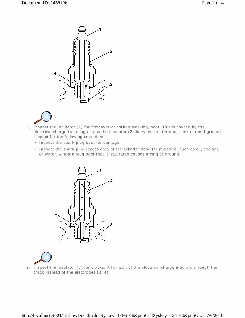
2. Inspect the insulator (2) for flashover or carbon tracking, soot. This is caused by the
electrical charge traveling across the insulator (2) between the terminal post (1) and ground. Inspect for the following conditions:
3. Inspect the insulator (2) for cracks. All or part of the electrical charge may arc through the
crack instead of the electrodes (3, 4).
• Inspect the spark plug boot for damage.
• Inspect the spark plug recess area of the cylinder head for moisture, such as oil, coolant, or water. A spark plug boot that is saturated causes arcing to ground.
Page 2 of 4Document ID: 1456106
7/6/2010http://localhost:9001/si/showDoc.do?docSyskey=1456106&pubCellSyskey=124160&pubO...

4. Inspect (3) for evidence of improper arcing.
5. Inspect the spark plug recess area of the cylinder head for debris. Dirty or damaged threads can cause the spark plug not to seat correctly during installation.
Spark Plug Visual Inspection
• Measure the gap between the center electrode (4) and the side electrode (3) terminals. An excessively wide electrode gap can prevent correct spark plug operation.
• Inspect for the correct spark plug torque. Insufficient torque can prevent correct spark plug operation. An over torqued spark plug, causes the insulator (2) to crack.
• Inspect for signs of tracking that occurred near the insulator tip instead of the center electrode (4).
• Inspect for a broken or worn side electrode (3).
• Inspect for a broken, worn, or loose center electrode (4) by shaking the spark plug.
- A rattling sound indicates internal damage.
- A loose center electrode (4) reduces the spark intensity.
• Inspect for bridged electrodes (3, 4). Deposits on the electrodes (3, 4) reduce or eliminates the gap.
• Inspect for worn or missing platinum pads on the electrodes (3, 4), if equipped.
• Inspect for excessive fouling.
• Normal operation--Brown to grayish-tan with small amounts of white powdery deposits are normal combustion by-products from fuels with additives.
• Carbon fouled--Dry, fluffy black carbon, or soot caused by the following conditions:
- Rich fuel mixtures
• Leaking fuel injectors
• Excessive fuel pressure
• Restricted air filter element
• Incorrect combustion
Page 3 of 4Document ID: 1456106
7/6/2010http://localhost:9001/si/showDoc.do?docSyskey=1456106&pubCellSyskey=124160&pubO...

- Reduced ignition system voltage output
• Weak coils
• Worn ignition wires
• Incorrect spark plug gap
-
Excessive idling or slow speeds under light loads can keep spark plug temperatures so low that normal combustion deposits may not burn off.
• Deposit fouling--Oil, coolant, or additives that include substances such as silicone, very white coating, reduces the spark intensity. Most powdery deposits will not effect spark intensity unless they form into a glazing over the electrode.
Page 4 of 4Document ID: 1456106
7/6/2010http://localhost:9001/si/showDoc.do?docSyskey=1456106&pubCellSyskey=124160&pubO...

2009 Chevrolet Aveo | Aveo, Wave, G3, Barina (VIN S/T) Service Manual | Engine | Engine Controls and Fuel - 1.2L | Repair Instructions | Document ID: 2137012
Spark Plug Replacement
Removal Procedure
Caution: Observe the following service precautions:
1. Turn OFF the ignition.
2. Remove the spark plug wires from the spark plugs. Refer to Spark Plug Wire Replacement. 3. Remove the spark plugs from the engine.
Installation Procedure
Caution: It is important to check the gap of all new and reconditioned spark plugs before installation. Pre-set gaps may have changed during handling. Use a round wire feeler gauge to be sure of an accurate check, particularly on used plugs. Installing plugs with the wrong gap can cause poor engine performance and may even damage the engine.
1. Gap the spark plugs to the specifications.
• Allow the engine to cool before removing the spark plugs. Attempting to remove spark plugs from a hot engine can cause the spark plugs to seize. This can damage the cylinder head threads.
• Clean the spark plug recess area before removing the spark plug. Failure to do so can result in engine damage due to dirt or foreign material entering the cylinder head, or in contamination of the cylinder head threads. Contaminated threads may prevent proper seating of the new spark plug.
• Use only the spark plugs specified for use in the vehicle. Do not install spark plugs that are either hotter or colder than those specified for the vehicle. Installing spark plugs of another type can severely damage the engine.
© 2010 General Motors Corporation. All rights reserved.
Page 1 of 2Document ID: 2137012
7/6/2010http://localhost:9001/si/showDoc.do?docSyskey=2137012&pubCellSyskey=124161&pubO...

Caution: Refer to Fastener Caution in the Preface section.
Caution: Be sure plug threads smoothly into cylinder head and is fully seated. Use a thread chaser if necessary to clean threads in cylinder head. Cross-threading or failing to fully seat spark plug can cause overheating of plug, exhaust blow-by, or thread damage. Follow the recommended torque specifications carefully. Over or under-tightening can also cause severe damage to engine or spark plug.
2. Install the spark plugs to the engine.
Tighten Tighten the spark plugs to 25 N·m (18 lb ft).
3. Install the spark plug wires to the spark plugs. Refer to Spark Plug Wire Replacement.
Page 2 of 2Document ID: 2137012
7/6/2010http://localhost:9001/si/showDoc.do?docSyskey=2137012&pubCellSyskey=124161&pubO...

2009 Chevrolet Aveo | Aveo, Wave, G3, Barina (VIN S/T) Service Manual | Engine | Engine Controls and Fuel - 1.2L | Repair Instructions | Document ID: 2042876
Crankshaft Position Sensor Replacement
Removal Procedure
Warning: Refer to Battery Disconnect Warning in the Preface section.
1. Disconnect the battery negative cable. Refer to Battery Negative Cable Disconnection and
Connection. 2. Disconnect the crankshaft position (CKP) sensor connector (1). 3. Remove the CKP sensor retaining bolt. 4. Remove the CKP sensor.
Installation Procedure
© 2010 General Motors Corporation. All rights reserved.
Page 1 of 2Document ID: 2042876
7/6/2010http://localhost:9001/si/showDoc.do?docSyskey=2042876&pubCellSyskey=124162&pubO...
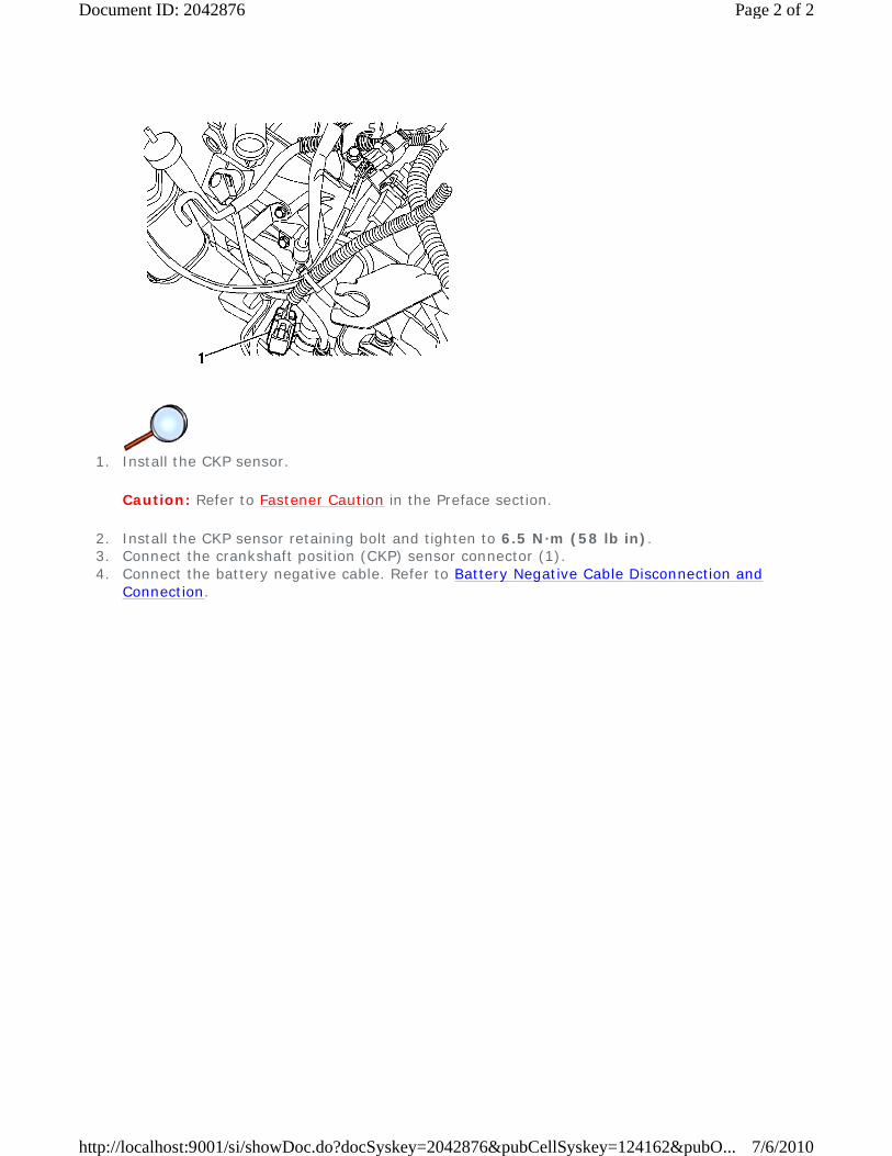
1. Install the CKP sensor.
Caution: Refer to Fastener Caution in the Preface section.
2. Install the CKP sensor retaining bolt and tighten to 6.5 N·m (58 lb in). 3. Connect the crankshaft position (CKP) sensor connector (1). 4. Connect the battery negative cable. Refer to Battery Negative Cable Disconnection and
Connection.
Page 2 of 2Document ID: 2042876
7/6/2010http://localhost:9001/si/showDoc.do?docSyskey=2042876&pubCellSyskey=124162&pubO...

2009 Chevrolet Aveo | Aveo, Wave, G3, Barina (VIN S/T) Service Manual | Engine | Engine Controls and Fuel - 1.2L | Repair Instructions | Document ID: 2042875
Camshaft Position Sensor Replacement
Removal Procedure
Note: A small amount of engine oil may be lost after removal of the camshaft position sensor.
1. Remove the ignition coil. 2. Disconnect the sensor electrical connector (1). 3. Remove the camshaft position (CMP) sensor bolt (3) and sensor (2).
Installation Procedure
Caution: Refer to Fastener Caution in the Preface section.
© 2010 General Motors Corporation. All rights reserved.
Page 1 of 2Document ID: 2042875
7/6/2010http://localhost:9001/si/showDoc.do?docSyskey=2042875&pubCellSyskey=124163&pubO...

1. Install the CMP sensor (2) and bolts (3) and tighten to 12 N·m (106 lb in). 2. Connect the sensor electrical connector (1). 3. Install the ignition coil.
Page 2 of 2Document ID: 2042875
7/6/2010http://localhost:9001/si/showDoc.do?docSyskey=2042875&pubCellSyskey=124163&pubO...
2009 Chevrolet Aveo | Aveo, Wave, G3, Barina (VIN S/T) Service Manual | Engine | Engine Controls and Fuel - 1.2L | Repair Instructions | Document ID: 2097943
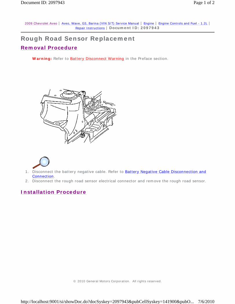
Rough Road Sensor Replacement
Removal Procedure
Warning: Refer to Battery Disconnect Warning in the Preface section.
1. Disconnect the battery negative cable. Refer to Battery Negative Cable Disconnection and
Connection. 2. Disconnect the rough road sensor electrical connector and remove the rough road sensor.
Installation Procedure
© 2010 General Motors Corporation. All rights reserved.
Page 1 of 2Document ID: 2097943
7/6/2010http://localhost:9001/si/showDoc.do?docSyskey=2097943&pubCellSyskey=141900&pubO...

1. Install the rough road sensor and connect the electrical connector. 2. Connect the battery negative cable. Refer to Battery Negative Cable Disconnection and
Connection.
Page 2 of 2Document ID: 2097943
7/6/2010http://localhost:9001/si/showDoc.do?docSyskey=2097943&pubCellSyskey=141900&pubO...
2009 Chevrolet Aveo | Aveo, Wave, G3, Barina (VIN S/T) Service Manual | Engine | Engine Controls and Fuel - 1.2L | Repair Instructions | Document ID: 2042862
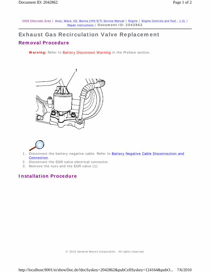
Exhaust Gas Recirculation Valve Replacement
Removal Procedure
Warning: Refer to Battery Disconnect Warning in the Preface section.
1. Disconnect the battery negative cable. Refer to Battery Negative Cable Disconnection and
Connection. 2. Disconnect the EGR valve electrical connector. 3. Remove the nuts and the EGR valve (1)
Installation Procedure
© 2010 General Motors Corporation. All rights reserved.
Page 1 of 2Document ID: 2042862
7/6/2010http://localhost:9001/si/showDoc.do?docSyskey=2042862&pubCellSyskey=124164&pubO...

1. Clean the mating surface. 2. Install a new EGR valve gasket.
Caution: Refer to Fastener Caution in the Preface section.
3. Install the EGR valve (1) with the retaining nuts and tighten to 30 N·m (22 lb ft). 4. Connect the EGR valve electrical connector. 5. Connect the battery negative cable. Refer to Battery Negative Cable Disconnection and
Connection.
Page 2 of 2Document ID: 2042862
7/6/2010http://localhost:9001/si/showDoc.do?docSyskey=2042862&pubCellSyskey=124164&pubO...
2009 Chevrolet Aveo | Aveo, Wave, G3, Barina (VIN S/T) Service Manual | Engine | Engine Controls and Fuel - 1.2L | Repair Instructions | Document ID: 2042866
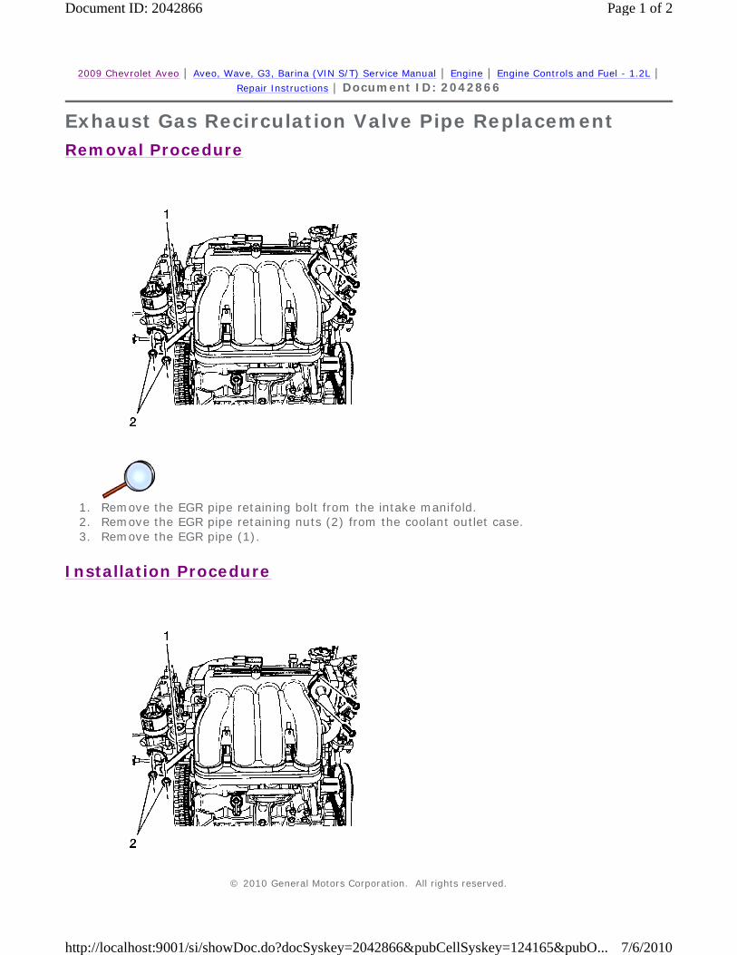
Exhaust Gas Recirculation Valve Pipe Replacement
Removal Procedure
1. Remove the EGR pipe retaining bolt from the intake manifold. 2. Remove the EGR pipe retaining nuts (2) from the coolant outlet case. 3. Remove the EGR pipe (1).
Installation Procedure
© 2010 General Motors Corporation. All rights reserved.
Page 1 of 2Document ID: 2042866
7/6/2010http://localhost:9001/si/showDoc.do?docSyskey=2042866&pubCellSyskey=124165&pubO...

1. Install the EGR pipe (1). 2. Install and tighten the EGR pipe retaining nuts (2) from the coolant outlet case.
Caution: Refer to Fastener Caution in the Preface section.
3. Install and tighten the EGR pipe retaining bolt from the intake manifold.
• Tighten the exhaust gas recirculation pipe retaining nuts to 10 N·m (89 lb in).
• Tighten the exhaust gas recirculation pipe retaining bolts to 22 N·m (16.2 lb in).
Page 2 of 2Document ID: 2042866
7/6/2010http://localhost:9001/si/showDoc.do?docSyskey=2042866&pubCellSyskey=124165&pubO...

2009 Chevrolet Aveo | Aveo, Wave, G3, Barina (VIN S/T) Service Manual | Engine | Engine Controls and Fuel - 1.2L | Repair Instructions | Document ID: 2044852
Air Cleaner Element Replacement
Removal Procedure
1. Remove the air filter upper housing. 2. Remove the air filter element (1).
Installation Procedure
1. Install the air filter element (1).
Caution: Refer to Fastener Caution in the Preface section.
© 2010 General Motors Corporation. All rights reserved.
Page 1 of 2Document ID: 2044852
7/6/2010http://localhost:9001/si/showDoc.do?docSyskey=2044852&pubCellSyskey=124166&pubO...

2. Replace the air filter upper housing bolts and tighten to 2 N·m (1.5 lb ft).
Page 2 of 2Document ID: 2044852
7/6/2010http://localhost:9001/si/showDoc.do?docSyskey=2044852&pubCellSyskey=124166&pubO...

2009 Chevrolet Aveo | Aveo, Wave, G3, Barina (VIN S/T) Service Manual | Engine | Engine Controls and Fuel - 1.2L | Repair Instructions | Document ID: 1551575
Idle Learn The Idle Learn Procedure listed below must be performed whenever the following occurs:
1. Turn the ignition ON. 2. Turn the ignition OFF for 15 seconds. 3. Turn the ignition ON for 5 seconds. 4. Turn the ignition OFF for 15 seconds. 5. Start the engine in park/neutral. 6. Allow the engine to run until the engine coolant temperature is greater than 85°C (185°F). 7. Turn the A/C ON for 10 seconds, if equipped. 8. If the vehicle is equipped with an automatic transaxle, apply the parking brake. While
pressing the brake pedal, place the transaxle in drive (D) for 10 seconds. 9. Turn the A/C OFF for 10 seconds, if equipped.
10. If the vehicle is equipped with an automatic transaxle, while pressing the brake pedal, place the transaxle in park/neutral.
11. Turn the ignition OFF. The idle learn procedure is complete.
• The throttle body assembly is replaced
• The throttle body is cleaned
• The engine control module (ECM) is replaced
• The idle air control valve (IAC) is replaced
• Power disconnection (battery cable, ECM fuse, etc.) (Delphi ECM only)
© 2010 General Motors Corporation. All rights reserved.
Page 1 of 1Document ID: 1551575
7/6/2010http://localhost:9001/si/showDoc.do?docSyskey=1551575&pubCellSyskey=141899&pubO...