Embed Size (px)
Citation preview

© Festo Didactic 88461-00 85
In this exercise, you will become familiar with plate heat exchangers. You will set up a cooling and a heating loop passing through the same brazed plate heat exchanger and record the temperatures at all four ports to investigate the behavior of such a process.
The Discussion of this exercise covers the following points:
Description of a brazed plate heat exchanger
Typical applications
Characteristics of the brazed plate heat exchanger
Using the brazed plate heat exchanger
Description of a brazed plate heat exchanger
A brazed plate heat exchanger is a compact type of exchanger made of a series of thin, usually corrugated plates which, once joined, are designed to create cavities in which the process fluids flow. Each plate has four corner ports (one inlet and one outlet for each of the two fluids). When the plates are assembled, the ports line up to give access to the cavities. For each cavity, a pair of gaskets or restrictions blocks the access to one of the two fluids and lets the other one flow from the inlet to the outlet. By alternating the fluid admitted in each cavity between fluid 1 and fluid 2, one obtains a disposition similar to the one shown in Figure 2-39, where the heat exchanger is in the counterflow configuration. The alternating layers of cold and warm fluids separated by a thin and thermally conductive wall allows for a very good heat transfer between the fluids.
Figure 2-39. A brazed plate heat exchanger.
Once the stainless steel plates are assembled, they are brazed together to ensure the exchanger is completely sealed. The brazing process is similar to soldering, but the filling metal, usually copper, is melted at higher
Heat Exchangers (Optional Exercise)
Exercise 2-4
EXERCISE OBJECTIVE
DISCUSSION OUTLINE
DISCUSSION
Ex. 2-4 – Heat Exchangers (Optional Exercise) Discussion
86 © Festo Didactic 88461-00
temperatures (above 450°C [842°F]). Consequently, in this type of heat exchanger, the number of plates and the characteristics are determined during the design phase and remain fixed once built.
A plate heat exchanger is typically very efficient but causes important pressure drops to the fluids traveling through it. This can be a limiting factor for some processes.
Typical applications
Brazed plate heat exchangers are designed for high-temperature and high pressure applications. Since they cannot be opened, they are restricted to applications where fouling is negligible.
Characteristics of the brazed plate heat exchanger
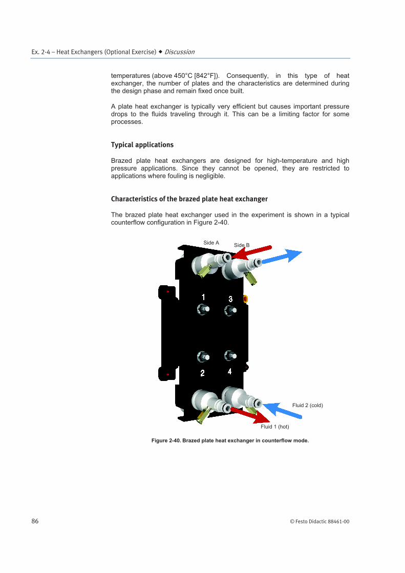
The brazed plate heat exchanger used in the experiment is shown in a typical counterflow configuration in Figure 2-40.
Figure 2-40. Brazed plate heat exchanger in counterflow mode.
Side A Side B
Fluid 1 (hot)
Fluid 2 (cold)

Ex. 2-4 – Heat Exchangers (Optional Exercise) Procedure Outline
© Festo Didactic 88461-00 87
Table 2-14 presents a summary of the main characteristics of the brazed plate heat exchanger:
Table 2-14. Brazed plate heat exchanger characteristics.
Characteristic Value
Nominal surface (A) 0.21 m2 (2.3 ft
2)
Number of plates 8
Number of channels (Side A) 4
Number of channels (Side B) 3
Using the brazed plate heat exchanger
To ensure an efficient heat transfer, as well as to extend the useful life of the brazed plate heat exchanger, some precautions must be taken. Be sure to:
Fasten the heat exchanger properly to the work surface and remember
that ports 1 and 2 are linked, as are ports 3 and 4.
The heat exchanger should be used in a counterflow configuration as it is
more efficient than a parallel-flow configuration.
Each side has two hose connectors that are used as the inlet port and outlet port for the hot or cold water. It does not matter which port is chosen for the inlet port or outlet port. The important thing is that the inlet and outlet connections must be made to ensure that the hot water and cold water circulate in a counter-current manner through the plate heat exchanger, as shown in Figure 2-40. If, for example, the hot water enters the exchanger through connector 1 and leaves through connector 2, then the cold water must enter the exchanger through connector 4 and leave through connector 3.
Each hose connector of the plate heat exchanger is equipped with a pressure port. The temperature at a pressure port can be measured by connecting a thermocouple probe to the port.
The Procedure is divided into the following sections:
Introduction
Set up and connectionsPreliminary setup. Calibration of the temperature transmitters. Purging air from the components downstream of the column. Activating the water loops.
Operation of the water heating/cooling systemHeat exchanger calculations.
Ending the exercise
PROCEDURE OUTLINE

Ex. 2-4 – Heat Exchangers (Optional Exercise) Procedure
88 © Festo Didactic 88461-00
Introduction
In certain situations, the temperature of a fluid must be kept at a given temperature. For example, a process may require a precise temperature in order for a chemical reaction to take place. This experiment simulates the case in which a fluid in a column produces heat via an exothermic reaction. This fluid needs to be kept at an optimal temperature using a heat exchanger in which a cooling fluid circulates.
Set up and connections
Preliminary setup
1. Connect the system as shown in Figure 2-41, Figure 2-42, Figure 2-43, and Figure 2-44. Do not perform the connections shown in blue in Figure 2-44 yet; this would compromise the calibration procedure performed later.
To ensure that the flows of the hot and cool water loops operate in counterflow mode in the heat exchanger, connect the outlet of the heating unit to connector 1 of the heat exchanger, and connector 2 to the top of the column, as shown in Figure 2-43. Also, connect the outlet of the cooling unit to connector 4 of the heat exchanger, and connector 3 to the pump of the cooling loop.
The controllers FC1 and FC2 will regulate the drive of the pumping units remotely. If you prefer, you can also control the pumps locally with the drive keypads.
The heating unit and cooling unit will be controlled manually. Because of this, no temperature controller (TC) appears next to these units in Figure 2-43.
Connect the thermocouple probes of transmitters TT1, TT2, TT3, and TT4 to the pressure ports on connectors 1, 2, 3, and 4 of the heat exchanger, respectively.
PROCEDURE

Ex. 2-4 – Heat Exchangers (Optional Exercise) Procedure
© Festo Didactic 88461-00 89
Figure 2-41. Heat exchanger setup Heating loop highlighted.
1 - Column 5 - Heat exchanger
2 - Heating unit 6 - Cooling unit
3 - Power supply 7 - Thermocouple temperature transmitter module
4 - Rotameters
Pump 2
Pump 1
Back view

Ex. 2-4 – Heat Exchangers (Optional Exercise) Procedure
90 © Festo Didactic 88461-00
Figure 2-42. Heat exchanger setup Cooling loop highlighted.
1 - Column 5 - Heat exchanger
2 - Heating unit 6 - Cooling unit
3 - Power supply 7 - Thermocouple temperature transmitter module
4 - Rotameters
Pump 2
Pump 1
Back view

Ex. 2-4 – Heat Exchangers (Optional Exercise) Procedure
© Festo Didactic 88461-00 91
Figure 2-43. Flow diagram - Heat exchanger setup.
Pump 1 Pump 2
Hot side Cold side

Ex. 2-4 – Heat Exchangers (Optional Exercise) Procedure
92 © Festo Didactic 88461-00
Figure 2-44. Wiring diagram - Heat exchanger setup.
LVProSim
Figure 2-44 shows how to connect the computer running LVProSim to the pumps and thermocouple temperature transmitter module via the I/O interface. With this setup the two pumps are controlled using the software.
To control the pumps speed using LVProSim, connect each of the variable-speed drives to an output of the I/O interface. With this configuration, you can modify the speed of a pump by changing the output signal manually in the appropriate PID controller section of LVProSim.

Ex. 2-4 – Heat Exchangers (Optional Exercise) Procedure
© Festo Didactic 88461-00 93
2. Adjust the equipment to the settings shown in Table 2-15.
Table 2-15. Equipment settings.
Equipment Knob or switch Setting
Heating unit S1 2
Manual control knob Fully counterclockwise
Cooling unit
S1 2
Manual control knob Fully counterclockwise
S2
All four thermocouple
temperature transmitters
INPUT CAL. SOURCE
CALIBRATION VARIABLE
ZERO MAX.
SPAN MAX.
3. If you control the pumps remotely, make sure controllers FC1 and FC2 are in the manual mode. Set the output of these controllers to 0% (4 mA).
4. Turn on the power supply. This powers up the I/O interface, the cooling unit, and the thermocouple temperature transmitter module. Leave both pumping units and the heating unit turned off.
Never power up the heating unit in the absence of water flow through this unit. Failure to
do so might cause the heating unit to wear out prematurely.
Calibration of the temperature transmitters
5. Calibrate the output of each of the four thermocouple temperature transmitters so that the output signal goes from 0% to 100% (4 mA to 20 mA) when the probe temperature simulated by the calibration source is increased from 25°C to 55°C (77°F to 131°F).
a Use the method outlined in steps 8 through 12 of Ex. 2-1 for the calibration of the outputs of the transmitters using the calibration source.
6. Once the four thermocouple temperature transmitters are calibrated, set the INPUT switch of each transmitter to THERMOCOUPLE.
Connect the 4-20 mA output of transmitters TT1, TT2, TT3, and TT4 to inputs 1, 2, 3 and 4, respectively, of the I/O interface (blue connections in Figure 2-44).

Ex. 2-4 – Heat Exchangers (Optional Exercise) Procedure
94 © Festo Didactic 88461-00
Purging air from the components downstream of the column
7. On the column, make sure the cap is tightened firmly and the plugs are in place.
8. Make sure the reservoir of each pumping unit is filled with about 12 liters (3.2 gal) of water. Make sure the baffle plate is properly installed at the bottom of each reservoir.
a You must add algaecide and rust inhibitor to the water when you fill the reservoirs. Refer to step 19 of Ex. 2-1 for precise quantities.
9. On pumping unit 1, adjust valves HV1 through HV3 using Table 2-16.
Table 2-16. Valves settings.
Valve Position
HV1 Open
HV2 Closed
HV3 Fully clockwise15
10. Turn on pumping unit 1. Adjust the parameters of the drive to either local or remote mode depending on the way you want to control the speed of the drive.
Leave pumping unit 2 and the heating unit turned off.
11. Press the Run button on the drive keypad of pumping unit 1 to start the pump.
12. Set the variable-speed drive of pumping unit 1 to maximum speed.
13. Allow the level of the water to rise in the pressurized column until it stabilizes at some intermediate level. This forces air out of the components downstream of the column.
Activating the water loops
14. On pumping unit 1, close valve HV1. Then set valve HV3 for directing the full return flow to the pump inlet (turn handle fully counterclockwise).
15. Open valve HV2 in order to decrease the water level in the column to 7.5 cm (3 in), then close this valve.
15
To direct the full reservoir flow to the pump inlet

Ex. 2-4 – Heat Exchangers (Optional Exercise) Procedure
© Festo Didactic 88461-00 95
16. Remove the cap to depressurize the column.
17. Adjust the variable-speed drive of pumping unit 1 until you have a flow rate of about 3 L/min (0.75 gal/min).
The first loop (with the heating unit turned off for now) is in operation. You will now activate the second loop (with the cooling unit).
18. On pumping unit 2, adjust valves HV1 through HV3 (identified as HV4 through HV6, respectively, in Figure 2-43) using Table 2-17.
Table 2-17. Valves settings.
Valve Position
HV1 Open
HV2 Closed
HV3 Fully clockwise
19. Turn on pumping unit 2. Adjust the parameters of the drive to either local or remote mode depending on the way you want to control the speed of the drive.
20. Press the Run button on the drive keypad of pumping unit 2 to start the pump.
21. Set the variable-speed drive of the pumping unit for maximum speed. Wait 30 seconds.
22. On pumping unit 2, close valve HV1. Then set valve HV3 for directing the full return flow to the pump inlet (turn handle fully counterclockwise).
23. Adjust the variable-speed drive of pumping unit 2 until you have a flow rate of about 3 L/min (0.75 gal/min).
Both loops are now in operation.
Ex. 2-4 – Heat Exchangers (Optional Exercise) Procedure
96 © Festo Didactic 88461-00
Operation of the water heating/cooling system
24. Plot the output signal of each thermocouple temperature transmitter (TT1 through TT4) on the trend recorder. See below for detailed instructions.
LVProSim
Figure 2-44 shows how to connect the computer running LVProSim to the pumps and temperature transmitter. Follow the steps below to plot the four transmitter output signals in the software. Configure each thermocouple to read a temperature between 25°C and 55°C (77°F and 131°F).
For each channel, press the Set Channels icon in the LVProSim menu bar and, in the Set Channels window, configure the four channels as detailed below.
• Enter the name you want to give to the channel in the Label section. • Select Temperature as the type of measured variable. • Select Celsius (or Fahrenheit) as the measurement unit. • Enter 25°C (77°F) in the Minimum value field and 55°C (131°F) in the
Maximum value field. These values correspond to 4 mA and 20 mA signals respectively.
From the Settings menu, change the sampling interval to 1000 ms. Add all four channels to the curves list and press the play button in the menu bar to start recording data.
25. On the cooling unit, turn the manual control knob fully clockwise to make the fans rotate at maximum speed.
26. Turn on the heating unit. Turn the manual control knob fully clockwise to apply the maximum electrical power to the heating element.
27. Allow the signals from the four temperature transmitters, TT1 through TT4, to increase and stabilize, which may require around 40 minutes.
28. Save the data to plot the results after the experiment.
29. When the signals from temperature transmitters TT1 through TT4 are stable on the trend recorder, the process is in a state of thermal equilibrium.
Record the temperatures measured by the thermocouples at equilibrium in the table below.

Ex. 2-4 – Heat Exchangers (Optional Exercise) Procedure
© Festo Didactic 88461-00 97
Table 2-18. Temperatures measured by TT1 through TT4 at equilibrium.
Transmitter Temperature
TT1 (hot side inlet)
TT2 (hot side outlet)
TT3 (cold side outlet)
TT4 (cold side inlet)
30. On the cooling unit, turn the manual control knob fully counterclockwise.
31. On the heating unit, turn the manual control knob fully counterclockwise. Turn off the heating unit.
32. Set the variable-speed drive of pumping unit 1 and 2 to minimum speed. Turn off the pumping units.
Heat exchanger calculations
33. Based on the temperatures recorded in Table 2-18, calculate the temperature decrease between the inlet and outlet of the hot side of the heat exchanger:
Temperature decrease = TT1 – TT2:
34. Based on the temperatures recorded in Table 2-18, calculate the temperature increase between the inlet and outlet of the cold side of the heat exchanger:
Temperature increase = TT3 – TT4:
35. In theory, at equilibrium, the thermal energy lost by the water flowing through the hot side of the heat exchanger is all gained by the water flowing through the cold side of the heat exchanger.
This implies that the decrease in temperature on the hot side of the heat exchanger (TT1 – TT2) should equal the increase in temperature on the cold side of the heat exchanger (TT3 – TT4), if the flow rates on both sides are equal.
Ex. 2-4 – Heat Exchangers (Optional Exercise) Conclusion
98 © Festo Didactic 88461-00
According to the results you obtained in step 33 and step 34, is the decrease in temperature measured on the hot side of the heat exchanger equal to the increase in temperature measured on the cold side? Why?
Ending the exercise
36. On each pumping unit, open valves HV1 and HV2 completely to empty the water loops.
37. Disconnect all leads from the training system. Remove from the work surface the power supply, the temperature transmitter, and any electrical equipment not included in the water loops.
38. Disconnect the hoses. Return all leads, hoses, and components to their storage location.
Hot water may remain in the hoses and components. The training system is not
equipped with dripless connectors, so be careful not to allow water to enter the
electrical components and their terminals upon disconnection of the hoses.
39. Wipe off any water from the floor and the Process Control Training System.
In this exercise, you familiarized yourself with heat exchangers of the plate type. You learned that this type of heat exchanger consists of thin plates that are pressed together and arranged in such a way as to make the hotter and the cooler fluids flow in a counter-current manner through alternating passages.
You set up a water heating/cooling system that uses a heating loop and a cooling loop connected through the medium of a brazed-plate heat exchanger. You observed that, in the heat exchanger, part of the thermal energy contained in the heated water is transferred to the water circulated by the cooling loop. In industrial systems, this allows excessive heat from the heating loop to be dumped into the cooling loop and permits achievement of a balanced operating condition.
CONCLUSION

Ex. 2-4 – Heat Exchangers (Optional Exercise) Review Questions
© Festo Didactic 88461-00 99
1. Describe a brazed plate heat exchanger.
2. For a heat exchanger, which is more efficient: parallel flow or counterflow?
3. Explain why a temperature gradient (difference) between the two process fluids is important for heat exchangers?
4. What is the main condition (assuming the heat exchange occurs without loss) for the decrease in water temperature measured on the hot side to be equal to the increase in water temperature measured on the cold side of the exchanger?
5. What would be the effect on the measured temperatures of injecting colder water into the reservoir of the second pumping unit into the cooling water loop?
REVIEW QUESTIONS