Embed Size (px)
Citation preview
1
New Product
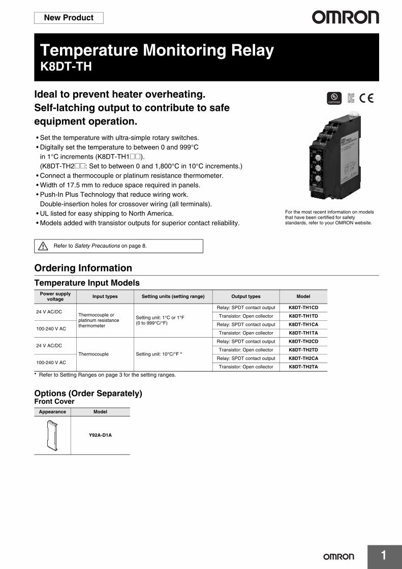
Temperature Monitoring RelayK8DT-TH
Ideal to prevent heater overheating.Self-latching output to contribute to safe equipment operation.
• Set the temperature with ultra-simple rotary switches.• Digitally set the temperature to between 0 and 999°C
in 1°C increments (K8DT-TH1@@).(K8DT-TH2@@: Set to between 0 and 1,800°C in 10°C increments.)
• Connect a thermocouple or platinum resistance thermometer.• Width of 17.5 mm to reduce space required in panels.• Push-In Plus Technology that reduce wiring work.
Double-insertion holes for crossover wiring (all terminals).• UL listed for easy shipping to North America.• Models added with transistor outputs for superior contact reliability.
Ordering InformationTemperature Input Models
* Refer to Setting Ranges on page 3 for the setting ranges.
Options (Order Separately)Front Cover
For the most recent information on models that have been certified for safety standards, refer to your OMRON website.
Refer to Safety Precautions on page 8.
Power supply voltage Input types Setting units (setting range) Output types Model
24 V AC/DCThermocouple or platinum resistance thermometer
Setting unit: 1°C or 1°F (0 to 999°C/°F)
Relay: SPDT contact output K8DT-TH1CD
Transistor: Open collector K8DT-TH1TD
100-240 V ACRelay: SPDT contact output K8DT-TH1CA
Transistor: Open collector K8DT-TH1TA
24 V AC/DC
Thermocouple Setting unit: 10°C/°F *
Relay: SPDT contact output K8DT-TH2CD
Transistor: Open collector K8DT-TH2TD
100-240 V ACRelay: SPDT contact output K8DT-TH2CA
Transistor: Open collector K8DT-TH2TA
Appearance Model
Y92A-D1A
K8DT-TH
2
Ratings and SpecificationsRatings Specifications
* Industrial Electromagnetic Environment (EN/IEC 61326-1, Table 2)
Power supply voltage
K8DT-TH@@D: 24 VAC 50/60 Hz or 24 VDCK8DT-TH@@A: 100 to 240 VAC 50/60 Hz
Allowable voltage range 85% to 110% of power supply voltage
Power consumption
24 VAC or 24 VDC: 2.1 VA max. or 1.2 W max.100 to 240 VAC: 3.1 VA max.
Rated insulation voltage 253 VAC
Sensor inputs
K8DT-TH1 Thermocouple: K, J, T, E; Platinum-resistance thermometer: Pt100, Pt1000
K8DT-TH2 Thermocouple: K, J, T, E, B, R, S, PL II
Setting method Set of three rotary DIP switches
Indicators Power (PWR): Green, Alarm (ALM): Red
Output form Relay: SPDT contact outputTransistor: Open collector
Output relay ratings
Rated load5 A at 250 VAC (Resistive load)5 A at 30 VDC (Resistive load)1 A at 250 VAC (Inductive load)0.2 A at 48 VDC (Inductive load)
Minimum load: 5 VDC, 10 mA (reference values)Mechanical life: 10 million operations min.Electrical life: 5 A at 250 VAC or 30 VDC: 50,000
operations3 A at 250 VAC/30 VDC: 100,000 operations
Transistor output ratings
Contact form: SPST-NO (Open collector)Rated voltage: 24 VDC (maximum voltage: 26.4 VDC)Maximum current: 50 mA DC
Ambient operating temperature 20 to 60°C (with no condensation or icing)
Storage temperature 25 to 65°C (with no condensation or icing)
Ambient operating humidity 25% to 85% RH (with no condensation)
Storage humidity 25% to 85% RH (with no condensation)
Altitude 2,000 m max.
Applicable wires Stranded wires, solid wires, or ferrules
Applicable wire size 0.25 to 1.5 mm2 (AWG24 to AWG16)
Wire insertion force 8 N max. for AWG20 wire
Screwdriver insertion force 15 N max.
Wire stripping length 8 mm
Ferrule length 8 mm
Current capacity 10 A (per pole)
Number of insertions 50 times
Case color N1.5
Case material PC, UL 94 V-0
Weight Approx. 100 g
Mounting Mounts to DIN Track, or screw mounting
Dimensions 17.5 90 90 mm (WDH)
Measurement accuracy
K8DT-TH1@@: ±1% of the setting range or ±4 °C, whichever is larger.K8DT-TH2@@: ±1% of the setting range (±1%FS).
Hysteresis width 2°C
Sampling cycle 100 ms
Applicable standards
Approved standards
EN 61010-1Installation environment: Overvoltage category II, pollution level 2
EMC EN 61326-1 *
Safety standards
UL 61010-1 (Listing)Korean Radio Waves Act (Act 10564)
Insulation resistance
20 M min.Between all external terminals and the caseBetween all power supply terminals and all input terminalsBetween all power supply terminals and all output terminalsBetween all input terminals and all output terminals
Dielectric strength
3,000 VAC for 1 minBetween all external terminals and the caseBetween all power supply terminals and all input terminalsBetween all power supply terminals and all output terminalsBetween all input terminals and all output terminals
Impulse withstand voltage
6 kV (between live terminals and exposed, non-charged metal parts)
Noise immunity
Square-wave noise of 1 s/100 ns pulse width with 1-ns rise time100 to 240 VAC: 1,500 V power supply terminal common/normal mode24 VAC: 1,500 V power supply terminal common/normal mode24 VDC: 480 V power supply terminal common
Vibration resistanceVibration of 10 to 55 Hz with a 0.35-mm half amplitude and acceleration of 50 m/s2 for 5 min with 10 sweeps each in X, Y, and Z directions
Shock resistance 100 m/s2, 3 times each in 6 directions along 3 axes
Degree of protection Terminals: IP20
K8DT-TH
3
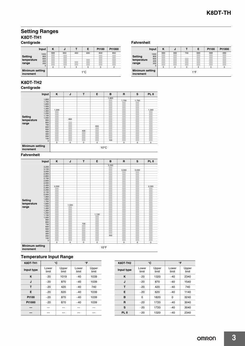
Setting RangesK8DT-TH1Centigrade Fahrenheit
K8DT-TH2Centigrade
Fahrenheit
Temperature Input Range
Input K J T E Pt100 Pt1000
Setting temperaturerange
1000800600400200
0
999 850 400 600 850 850
? ? ?
0 0 0 0 0 0
Minimum setting increment 1°C
Input K J T E Pt100 Pt1000
Setting temperaturerange
1000800600400200
0
999 999 700 999 999 999? ?
? ? ?
0 0 0 0 0 0
Minimum setting increment 1°F
Input K J T E B R S PL II
Setting temperaturerange
1,8001,7001,6001,5001,4001,3001,2001,1001,000
900800700600500400300200100
0
1,8001,700 1,700
1,300 1,300
850
600
400
1000 0 0 0 0 0 0
Minimum setting increment 10°C
Input K J T E B R S PL II
Setting temperaturerange
3,2003,1003,0002,9002,8002,7002,6002,5002,4002,3002,2002,1002,0001,9001,8001,7001,6001,5001,4001,3001,2001,1001,000
900800700600500400300200100
0
3,200
3,000 3,000
2,300 2,300
1,500
1,100
700
300
0 0 0 0 0 0 0
Minimum setting increment 10°F
K8DT-TH1 °C °F K8DT-TH2 °C °F
Input type Lower limit
Upper limit
Lower limit
Upper limit Input type Lower
limitUpper limit
Lower limit
Upper limit
K 20 1019 40 1039 K 20 1320 40 2340
J 20 870 40 1039 J 20 870 40 1540
T 20 420 40 740 T 20 420 40 740
E 20 620 40 1039 E 20 620 40 1140
Pt100 20 870 40 1039 B 0 1820 0 3240
Pt1000 20 870 40 1039 R 20 1720 40 3040
--- --- --- --- --- S 20 1720 40 3040
--- --- --- --- --- PL II 20 1320 40 2340
K8DT-TH
4
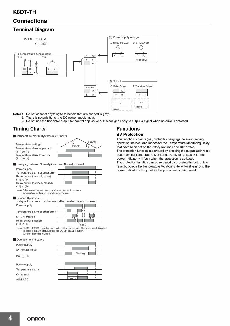
ConnectionsTerminal Diagram
Note: 1. Do not connect anything to terminals that are shaded in gray.2. There is no polarity for the DC power supply input.3. Do not use the transistor output for control applications. It is designed only to output a signal when an error is detected.
Timing Charts FunctionsSV ProtectionThis function protects (i.e., prohibits changing) the alarm setting, operating method, and modes for the Temperature Monitoring Relay that have been set on the rotary switches and DIP switch.The protection function is activated by pressing the output latch reset button on the Temperature Monitoring Relay for at least 5 s. The power indicator will flash when the protection is activated.The protection function can be released by pressing the output latch reset button on the Temperature Monitoring Relay for at least 5 s. The power indicator will light while the protection is being reset.
(1) Temperature sensor inputTH1 TH2
K8DT-TH1 C A(1) (2)(3)
B
B B
A A
B B
B
A1
B
14
A2
A
11
12
B
DIP SW
InsideInside
(2) Output
C: Relay Output T: Transistor Output
14 11
12
14 11
(3) Power supply voltage
A: 100 to 240 VAC D: 24 VAC/VDC
(No polarity)
A1 A2 A1 A2
Relay output (normally closed) (11) to (14)
Relay output (normally open) (11) to (14)
Temperature alarm or other errorPower supply
Relay output (latched) (11) to (14)
LATCH_RESET
Temperature alarm or other error
Power supply
PWR_LED
SV Protect Mode
Power supply
ALM_LED
Temperature alarm
Power supply
Other error
Temperature alarm lower limit (11) to (14)
Temperature alarm upper limit (11) to (14)
Temperature settings
Note: Other errors: sensor open circuit error, sensor input error, temperature setting error, and memory error.
0.02 s
2°C (°F)
2°C (°F)
Flashing
Flashing
Note: If LATCH_RESET is enabled, alarm status will be retained even if the power supply is cycled.To clear the alarm status, press the LATCH_RESET button.(Default: Latching enabled.)
Temperature Alarm: Hysteresis: 2°C or 2°F
Changing between Normally Open and Normally Closed
Latched Operation: Relay outputs remain latched even after the alarm or error is reset.
Operation of Indicators
K8DT-TH
5
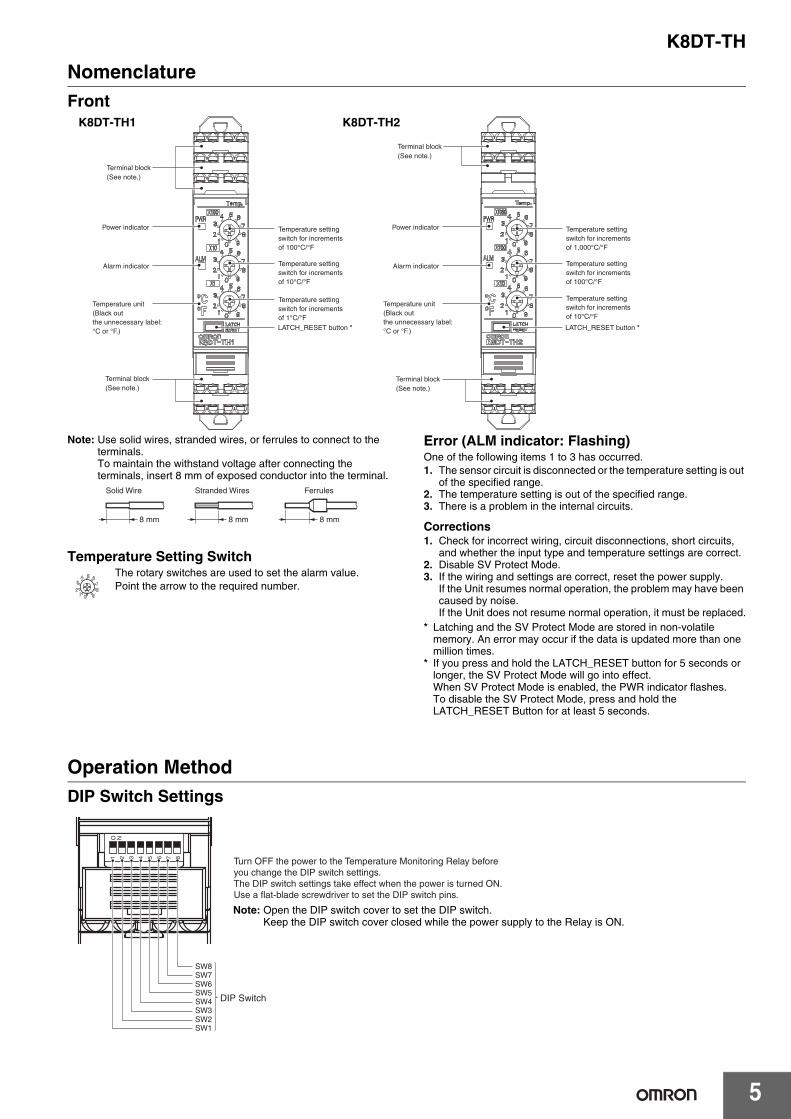
NomenclatureFront
Note: Use solid wires, stranded wires, or ferrules to connect to the terminals.To maintain the withstand voltage after connecting the terminals, insert 8 mm of exposed conductor into the terminal.
Temperature Setting SwitchThe rotary switches are used to set the alarm value.Point the arrow to the required number.
Error (ALM indicator: Flashing)One of the following items 1 to 3 has occurred.1. The sensor circuit is disconnected or the temperature setting is out
of the specified range.2. The temperature setting is out of the specified range.3. There is a problem in the internal circuits.
Corrections1. Check for incorrect wiring, circuit disconnections, short circuits,
and whether the input type and temperature settings are correct.2. Disable SV Protect Mode.3. If the wiring and settings are correct, reset the power supply.
If the Unit resumes normal operation, the problem may have been caused by noise.If the Unit does not resume normal operation, it must be replaced.
* Latching and the SV Protect Mode are stored in non-volatile memory. An error may occur if the data is updated more than one million times.
* If you press and hold the LATCH_RESET button for 5 seconds or longer, the SV Protect Mode will go into effect.When SV Protect Mode is enabled, the PWR indicator flashes.To disable the SV Protect Mode, press and hold the LATCH_RESET Button for at least 5 seconds.
Operation MethodDIP Switch Settings
Temperature unit(Black out the unnecessary label: °C or °F.)
Temperature setting switch for increments of 100°C/°F
Temperature setting switch for increments of 10°C/°F
Temperature setting switch for increments of 1°C/°FLATCH_RESET button *
Power indicator
Alarm indicator
Terminal block(See note.)
Terminal block(See note.)
Temperature unit(Black out the unnecessary label: °C or °F.)
Temperature setting switch for increments of 1,000°C/°F
Temperature setting switch for increments of 100°C/°F
Temperature setting switch for increments of 10°C/°F
LATCH_RESET button *
Power indicator
Alarm indicator
Terminal block(See note.)
Terminal block(See note.)
K8DT-TH1 K8DT-TH2
8 mm 8 mm
Solid Wire
8 mm
Stranded Wires Ferrules
O N1 2 3 4 5 6 7 8
SW3
DIP Switch
SW2SW1
SW4
SW7SW6SW5
SW8
Turn OFF the power to the Temperature Monitoring Relay before you change the DIP switch settings. The DIP switch settings take effect when the power is turned ON.Use a flat-blade screwdriver to set the DIP switch pins.
Note: Open the DIP switch cover to set the DIP switch.Keep the DIP switch cover closed while the power supply to the Relay is ON.
K8DT-TH
6
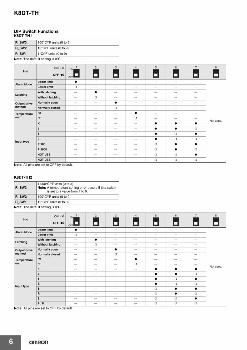
DIP Switch FunctionsK8DT-TH1
Note: The default setting is 0°C.
Note: All pins are set to OFF by default.
K8DT-TH2
Note: The default setting is 0°C.
Note: All pins are set to OFF by default.
R_SW3 100°C/°F units (0 to 9)
R_SW2 10°C/°F units (0 to 9)
R_SW1 1°C/°F units (0 to 9)
PINON ❍
OFF ●
Alarm ModeUpper limit ● --- --- --- --- --- ---
Not used.
Lower limit ❍ --- --- --- --- --- ---
LatchingWith latching --- ● --- --- --- --- ---
Without latching --- ❍ --- --- --- --- ---
Output drive method
Normally open --- --- ● --- --- --- ---
Normally closed --- --- ❍ --- --- --- ---
Temperature unit
°C --- --- --- ● --- --- ---
°F --- --- --- ❍ --- --- ---
Input type
K --- --- --- --- ● ● ●
J --- --- --- --- ● ● ❍
T --- --- --- --- ● ❍ ●
E --- --- --- --- ● ❍ ❍
Pt100 --- --- --- --- ❍ ● ●
Pt1000 --- --- --- --- ❍ ● ❍
NOT USE --- --- --- --- ❍ ❍ ●
NOT USE --- --- --- --- ❍ ❍ ❍
R_SW31,000°C/°F units (0 to 3)Note: A temperature setting error occurs if this switch
is set to a value from 4 to 9.
R_SW2 100°C/°F units (0 to 9)
R_SW1 10°C/°F units (0 to 9)
PINON ❍
OFF ●
Alarm ModeUpper limit ● --- --- --- --- --- ---
Not used.
Lower limit ❍ --- --- --- --- --- ---
LatchingWith latching --- ● --- --- --- --- ---
Without latching --- ❍ --- --- --- --- ---
Output drive method
Normally open --- --- ● --- --- --- ---
Normally closed --- --- ❍ --- --- --- ---
Temperature unit
°C --- --- --- ● --- --- ---
°F --- --- --- ❍ --- --- ---
Input type
K --- --- --- --- ● ● ●
J --- --- --- --- ● ● ❍
T --- --- --- --- ● ❍ ●
E --- --- --- --- ● ❍ ❍
B --- --- --- --- ❍ ● ●
R --- --- --- --- ❍ ● ❍
S --- --- --- --- ❍ ❍ ●
PL II --- --- --- --- ❍ ❍ ❍
1ON
OFF
2 3 4 5 6 7 8
1ON
OFF
2 3 4 5 6 7 8
K8DT-TH
7
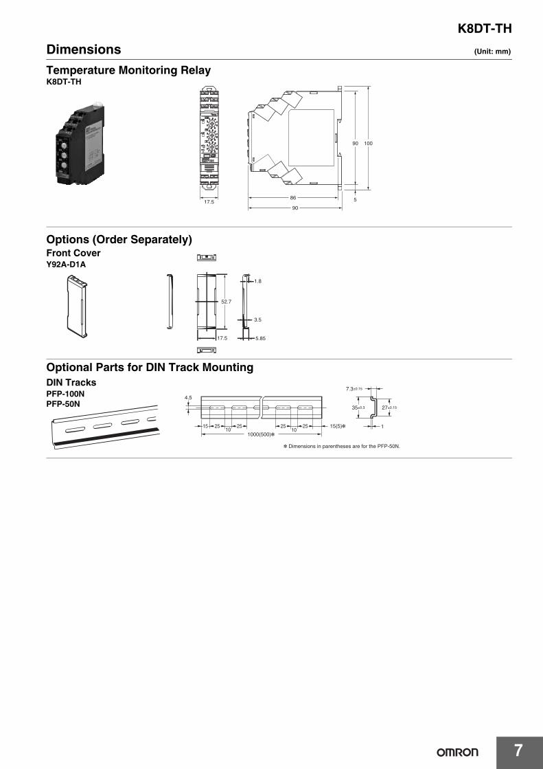
Dimensions (Unit: mm)
Optional Parts for DIN Track Mounting
17.5
90
86
90
5
100
Temperature Monitoring RelayK8DT-TH
Options (Order Separately)Front CoverY92A-D1A
52.7
3.5
1.8
17.5 5.85
DIN TracksPFP-100NPFP-50N
* Dimensions in parentheses are for the PFP-50N.
4.5
15 25 2510 10
1000(500)*25 25 15(5)*
35±0.3
7.3±0.15
27±0.15
1
K8DT-TH
8
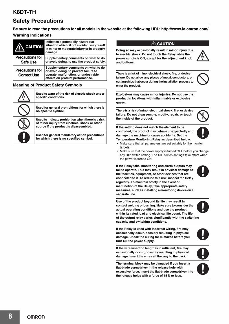
Safety PrecautionsBe sure to read the precautions for all models in the website at the following URL: http://www.ia.omron.com/.
Warning Indications
Meaning of Product Safety Symbols
!CAUTION
Doing so may occasionally result in minor injury due to electric shock. Do not touch the Relay while the power supply is ON, except for the adjustment knob and buttons.
There is a risk of minor electrical shock, fire, or device failure. Do not allow any pieces of metal, conductors, or cutting chips that occur during the installation process to enter the product.
Explosions may cause minor injuries. Do not use the product in locations with inflammable or explosive gases.
There is a risk of minor electrical shock, fire, or device failure. Do not disassemble, modify, repair, or touch the inside of the product.
If the setting does not match the element to be controlled, the product may behave unexpectedly and damage the machine or cause accidents. Set the Temperature Monitoring Relay as described below.• Make sure that all parameters are set suitably for the monitor
targets.• Make sure that the power supply is turned OFF before you change
any DIP switch setting. The DIP switch settings take effect when the power is turned ON.
If the Relay fails, monitoring and alarm outputs may fail to operate. This may result in physical damage to the facilities, equipment, or other devices that are connected to it. To reduce this risk, inspect the Relay regularly. To maintain safety in the event of malfunction of the Relay, take appropriate safety measures, such as installing a monitoring device on a separate line.
Use of the product beyond its life may result in contact welding or burning. Make sure to consider the actual operating conditions and use the product within its rated load and electrical life count. The life of the output relay varies significantly with the switching capacity and switching conditions.
If the Relay is used with incorrect wiring, fire may occasionally occur, possibly resulting in physical damage. Check the wiring for mistakes before you turn ON the power supply.
If the wire insertion length is insufficient, fire may occasionally occur, possibly resulting in physical damage. Insert the wires all the way to the back.
The terminal block may be damaged if you insert a flat-blade screwdriver in the release hole with excessive force. Insert the flat-blade screwdriver into the release holes with a force of 15 N or less.
CAUTIONIndicates a potentially hazardous situation which, if not avoided, may result in minor or moderate injury or in property damage.
Precautions for Safe Use
Supplementary comments on what to do or avoid doing, to use the product safely.
Precautions for Correct Use
Supplementary comments on what to do or avoid doing, to prevent failure to operate, malfunction, or undesirable effects on product performance.
Used to warn of the risk of electric shock under specific conditions.
Used for general prohibitions for which there is no specific symbol.
Used to indicate prohibition when there is a risk of minor injury from electrical shock or other source if the product is disassembled.
Used for general mandatory action precautions for which there is no specified symbol.
K8DT-TH
9
1. Do not use or store the product in the following locations.• Locations subject to water or oil• Locations subject to direct radiant heating equipment• Outdoor locations or under direct sunlight• Locations subject to dust or corrosive gases (sulfurizing gases,
ammonia gases, etc.)• Locations subject to rapid temperature changes• Locations prone to icing and dew condensation• Locations subject to vibration and large shocks• Locations subject to wind and rain• Locations subject to direct radiant heating equipment• Locations subject to static electricity or noise• Locations subject to insects or small animals
2. Use and store the product in a location where the ambient temperature and humidity are within the specified ranges. If applicable, provide forced cooling.
3. Check terminal polarity when wiring and wire all connections correctly. The power supply terminals do not have polarity.
4. Do not wire the input and output terminals incorrectly.5. Make sure the power supply voltage and loads are within the
specifications and ratings for the product.6. Make sure the type of the thermocouple matches the input type
that the Temperature Monitoring Relay is designed for.7. If you need to extend the length of the lead wires on the
thermocouple, make sure to match the type of thermocouple and always use compensating conductors.
8. Point the arrows on the rotary switches to the required numbers. Do not set a switch midway between two positions. Malfunction could result from an improper setting.
9. To extend the lead wires on the platinum resistance thermometer, use lead wires with a low resistance (5 or less per wire), and make the resistance equal on all three lead wires.
10.Make sure the ferrule terminals for wiring are of the specified size.11.The stripping length is 8 mm. Insert the wires all the way to the back.12.Do not connect anything to terminals that are not being used.13.Use a power supply that will reach the rated voltage within 1
second after the power is turned ON.14.After you turn ON the power, it takes 2 seconds for the outputs of
the Temperature Monitoring Relay to stabilize. Take this time into account when you design the control panel.
15.Allow at least 30 minutes for the product to warm up. During this time, the correct temperature will not be detected and the output may malfunction.
16.Keep wiring separate from high voltages and power lines that draw large currents. Do not place product wiring in parallel with or in the same path as high-voltage or high-current lines.
17.Do not install the product near equipment that generates high frequencies or surges.
18.The product may cause incoming radio wave interference. Do not use the product near radio wave receivers.
19.Install an external switch or circuit breaker and label it clearly so that the operator can quickly turn OFF the power supply.
20.When discarding the product, properly dispose of it as industrial waste.
21.Make sure the indicators operate correctly. Depending on the application environment, the indicators may deteriorate prematurely and become difficult to see.
22.The maximum terminal temperature is 80°C. Use wires with a temperature resistance of at least 80°C.
23.Do not use the product if it is accidentally dropped. The internal components may be damaged.
24.Be sure you understand the contents of this catalog and handle the product according to the instructions provided.
25.Do not install the product in any way that would place a load on it.26.When using the product, remember that the power supply
terminals carry a high voltage.27.The product must be handled only by trained electrician.28.Prior to operation, check the wiring before you supply power to the
product.29.Do not install the product immediately next to heat sources.30.Perform periodic maintenance.31.Do not wire anything to the release holes.32.When you insert a flat-blade screwdriver into a release hole, do not
tilt or twist the screwdriver. The terminal block may be damaged.33. Insert a flat-blade screwdriver into the release holes at an angle. The
terminal block may be damaged if the screwdriver is inserted straight in.34.Do not allow the flat-blade screwdriver to fall when you are holding
it in a release hole.
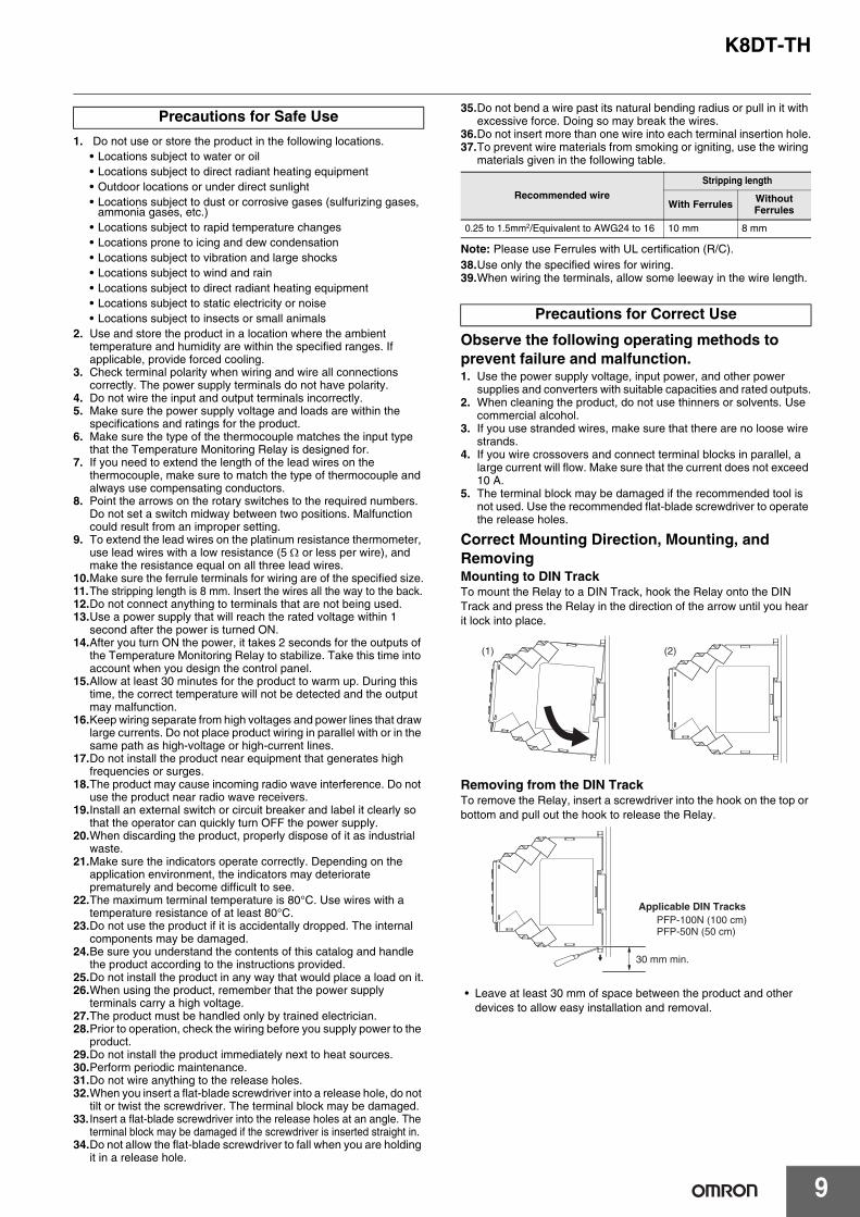
35.Do not bend a wire past its natural bending radius or pull in it with excessive force. Doing so may break the wires.
36.Do not insert more than one wire into each terminal insertion hole.37.To prevent wire materials from smoking or igniting, use the wiring
materials given in the following table.
Note: Please use Ferrules with UL certification (R/C).38.Use only the specified wires for wiring.39.When wiring the terminals, allow some leeway in the wire length.
Observe the following operating methods to prevent failure and malfunction.1. Use the power supply voltage, input power, and other power
supplies and converters with suitable capacities and rated outputs.2. When cleaning the product, do not use thinners or solvents. Use
commercial alcohol.3. If you use stranded wires, make sure that there are no loose wire
strands.4. If you wire crossovers and connect terminal blocks in parallel, a
large current will flow. Make sure that the current does not exceed 10 A.
5. The terminal block may be damaged if the recommended tool is not used. Use the recommended flat-blade screwdriver to operate the release holes.
Correct Mounting Direction, Mounting, and RemovingMounting to DIN TrackTo mount the Relay to a DIN Track, hook the Relay onto the DIN Track and press the Relay in the direction of the arrow until you hear it lock into place.
Removing from the DIN TrackTo remove the Relay, insert a screwdriver into the hook on the top or bottom and pull out the hook to release the Relay.
• Leave at least 30 mm of space between the product and other devices to allow easy installation and removal.
Precautions for Safe Use
Recommended wireStripping length
With Ferrules Without Ferrules
0.25 to 1.5mm2/Equivalent to AWG24 to 16 10 mm 8 mm
Precautions for Correct Use
(1) (2)
PFP-100N (100 cm)PFP-50N (50 cm)
Applicable DIN Tracks
30 mm min.
K8DT-TH
10
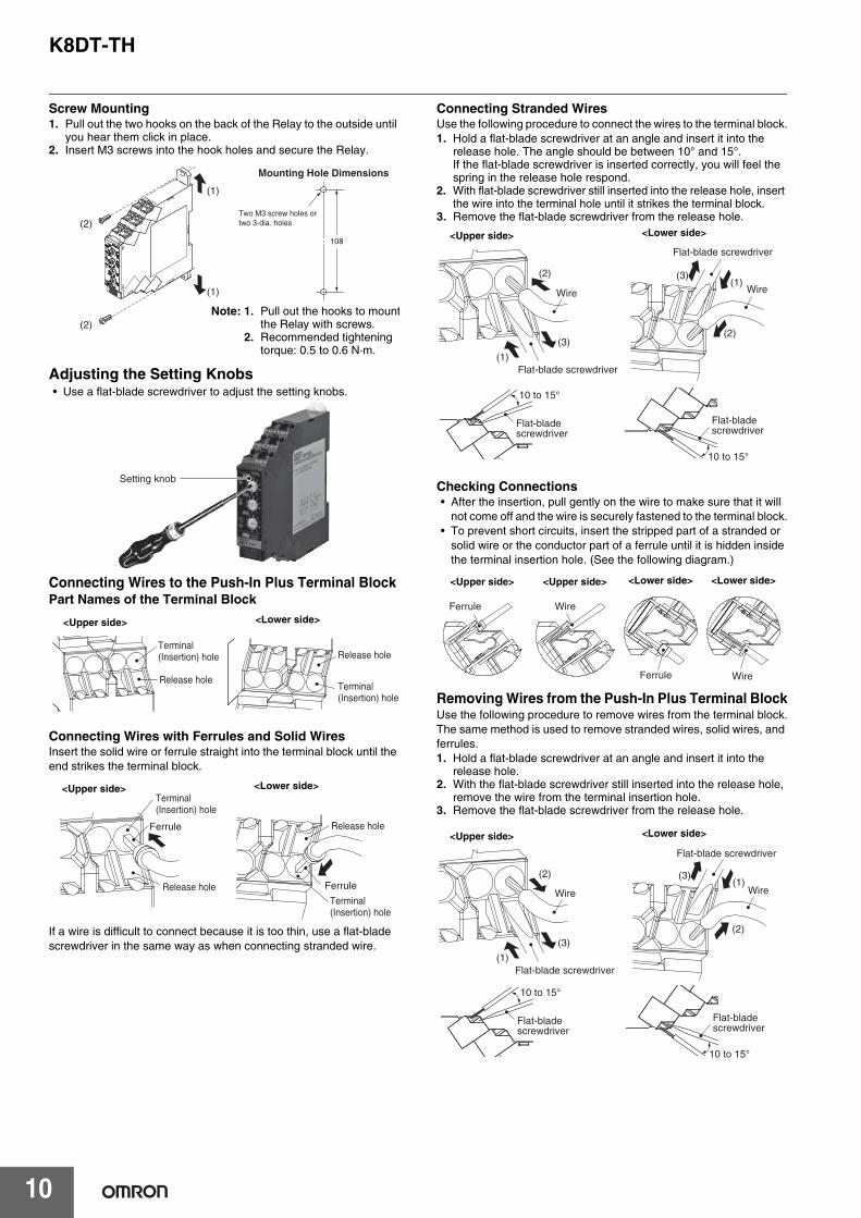
Screw Mounting1. Pull out the two hooks on the back of the Relay to the outside until
you hear them click in place.2. Insert M3 screws into the hook holes and secure the Relay.
Adjusting the Setting Knobs• Use a flat-blade screwdriver to adjust the setting knobs.
Connecting Wires to the Push-In Plus Terminal BlockPart Names of the Terminal Block
Connecting Wires with Ferrules and Solid WiresInsert the solid wire or ferrule straight into the terminal block until the end strikes the terminal block.
If a wire is difficult to connect because it is too thin, use a flat-blade screwdriver in the same way as when connecting stranded wire.
Connecting Stranded WiresUse the following procedure to connect the wires to the terminal block.1. Hold a flat-blade screwdriver at an angle and insert it into the
release hole. The angle should be between 10° and 15°.If the flat-blade screwdriver is inserted correctly, you will feel the spring in the release hole respond.
2. With flat-blade screwdriver still inserted into the release hole, insert the wire into the terminal hole until it strikes the terminal block.
3. Remove the flat-blade screwdriver from the release hole.
Checking Connections• After the insertion, pull gently on the wire to make sure that it will
not come off and the wire is securely fastened to the terminal block.• To prevent short circuits, insert the stripped part of a stranded or
solid wire or the conductor part of a ferrule until it is hidden inside the terminal insertion hole. (See the following diagram.)
Removing Wires from the Push-In Plus Terminal BlockUse the following procedure to remove wires from the terminal block.The same method is used to remove stranded wires, solid wires, and ferrules.1. Hold a flat-blade screwdriver at an angle and insert it into the
release hole.2. With the flat-blade screwdriver still inserted into the release hole,
remove the wire from the terminal insertion hole.3. Remove the flat-blade screwdriver from the release hole.
(1)
(1)
(2)
(2)
Two M3 screw holes ortwo 3-dia. holes
108
Mounting Hole Dimensions
Note: 1. Pull out the hooks to mountthe Relay with screws.
2. Recommended tightening torque: 0.5 to 0.6 N·m.
Setting knob
Release hole
Terminal (Insertion) hole Release hole
Terminal (Insertion) hole
<Upper side> <Lower side>
Ferrule
Release hole
Terminal (Insertion) hole
Ferrule
Release hole
Terminal (Insertion) hole
<Upper side> <Lower side>
Wire
Flat-blade screwdriver(1)
(3)
(2)
Wire
Flat-blade screwdriver
(1)
(2)
(3)
10 to 15°
10 to 15°
Flat-blade screwdriver
Flat-blade screwdriver
<Upper side> <Lower side>
Ferrule
Ferrule
<Upper side> <Lower side>
Wire
<Lower side>
Wire
<Upper side>
Wire
Flat-blade screwdriver(1)
(3)
(2)
Wire
Flat-blade screwdriver
(1)
(2)
(3)
10 to 15°
10 to 15°
Flat-blade screwdriver
Flat-blade screwdriver
<Upper side> <Lower side>
K8DT-TH
11
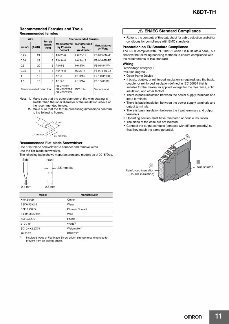
Recommended Ferrules and ToolsRecommended ferrules
Note: 1. Make sure that the outer diameter of the wire coating is smaller than the inner diameter of the insulation sleeve of the recommended ferrule.
2. Make sure that the ferrule processing dimensions conform to the following figures.
Recommended Flat-blade ScrewdriverUse a flat-blade screwdriver to connect and remove wires.Use the flat-blade screwdriver.The following table shows manufacturers and models as of 2015/Dec.
• Refer to the contents of this datasheet for cable selection and other conditions for compliance with EMC standards.
Precaution on EN Standard ComplianceThe K8DT complies with EN 61010-1 when it is built into a panel, but observe the following handling methods to ensure compliance with the requirements of this standard.
WiringOvervoltage category IIPollution degree 2• Open-frame Device• If basic, double, or reinforced insulation is required, use the basic,
double, or reinforced insulation defined in IEC 60664 that is suitable for the maximum applied voltage for the clearance, solid insulation, and other factors.
• There is basic insulation between the power supply terminals and input terminals.
• There is basic insulation between the power supply terminals and output terminals.
• There is basic insulation between the input terminals and output terminals.
• Operating section must have reinforced or double insulation.• The sides of the case are not isolated.• Connect the output contacts (contacts with different polarity) so
that they reach the same potential.
WireFerrulelength (mm)
Recommended ferrules
(mm2) (AWG)Manufactured
by Phoenix Contact
Manufactured by
Weidmuller
Manufactured by Wago
0.25 24 8 AI0.25-8 H0.25/12 FE-0.25-8N-YE
0.34 22 8 AI0.34-8 H0.34/12 FE-0.34-8N-TQ
0.5 20 8 AI0.5-8 H0.5/14 FE-0.5-8N-WH
0.75 18 8 AI0.75-8 H0.75/14 FE-0.75-8N-GY
1 18 8 AI1-8 H1.0/14 FE-1.0-8N-RD
1.5 16 8 AI1.5-8 H1.5/14 FE-1.5-8N-BK
Recommended crimp toolCRIMPFOX6CRIMPFOX6T-FCRIMPFOX10S
PZ6 roto Variocrimp4
Model Manufacturer
XW4Z-00B Omron
ESD0.40X2.5 Wera
SZF 0.4X2.5 Phoenix Contact
0.4X2.5X75 302 Wiha
AEF.2.5X75 Facom
210-719 Wago*1
*1. Insulated types of Flat-blade Screw driver, strongly recommended to prevent from an electric shock.
SDI 0.4X2.5X75 Weidmuller*1
98 20 25 KNIPEX*1
8 mm
2.1 mm max.2.7 mm max.
Side
0.4 mm
2.5 mm dia.
2.5 mm
Front
EN/IEC Standard Compliance
Not isolatedReinforced insulation
(Double insulation)

MEMO
12
Terms and Conditions AgreementRead and understand this catalog.
Please read and understand this catalog before purchasing the products. Please consult your OMRON representative if you have any questions or comments.
Warranties.(a) Exclusive Warranty. Omron’s exclusive warranty is that the Products will be free from defects in materials and workmanship
for a period of twelve months from the date of sale by Omron (or such other period expressed in writing by Omron). Omron disclaims all other warranties, express or implied.
(b) Limitations. OMRON MAKES NO WARRANTY OR REPRESENTATION, EXPRESS OR IMPLIED, ABOUT NON-INFRINGEMENT, MERCHANTABILITY OR FITNESS FOR A PARTICULAR PURPOSE OF THE PRODUCTS. BUYER ACKNOWLEDGES THAT IT ALONE HAS DETERMINED THAT THE PRODUCTS WILL SUITABLY MEET THE REQUIREMENTS OF THEIR INTENDED USE.
Omron further disclaims all warranties and responsibility of any type for claims or expenses based on infringement by the Products or otherwise of any intellectual property right. (c) Buyer Remedy. Omron’s sole obligation hereunder shall be, at Omron’s election, to (i) replace (in the form originally shipped with Buyer responsible for labor charges for removal or replacement thereof) the non-complying Product, (ii) repair the non-complying Product, or (iii) repay or credit Buyer an amount equal to the purchase price of the non-complying Product; provided that in no event shall Omron be responsible for warranty, repair, indemnity or any other claims or expenses regarding the Products unless Omron’s analysis confirms that the Products were properly handled, stored, installed and maintained and not subject to contamination, abuse, misuse or inappropriate modification. Return of any Products by Buyer must be approved in writing by Omron before shipment. Omron Companies shall not be liable for the suitability or unsuitability or the results from the use of Products in combination with any electrical or electronic components, circuits, system assemblies or any other materials or substances or environments. Any advice, recommendations or information given orally or in writing, are not to be construed as an amendment or addition to the above warranty.
See http://www.omron.com/global/ or contact your Omron representative for published information.
Limitation on Liability; Etc.OMRON COMPANIES SHALL NOT BE LIABLE FOR SPECIAL, INDIRECT, INCIDENTAL, OR CONSEQUENTIAL DAMAGES, LOSS OF PROFITS OR PRODUCTION OR COMMERCIAL LOSS IN ANY WAY CONNECTED WITH THE PRODUCTS, WHETHER SUCH CLAIM IS BASED IN CONTRACT, WARRANTY, NEGLIGENCE OR STRICT LIABILITY.
Further, in no event shall liability of Omron Companies exceed the individual price of the Product on which liability is asserted.
Suitability of Use.Omron Companies shall not be responsible for conformity with any standards, codes or regulations which apply to the combination of the Product in the Buyer’s application or use of the Product. At Buyer’s request, Omron will provide applicable third party certification documents identifying ratings and limitations of use which apply to the Product. This information by itself is not sufficient for a complete determination of the suitability of the Product in combination with the end product, machine, system, or other application or use. Buyer shall be solely responsible for determining appropriateness of the particular Product with respect to Buyer’s application, product or system. Buyer shall take application responsibility in all cases.
NEVER USE THE PRODUCT FOR AN APPLICATION INVOLVING SERIOUS RISK TO LIFE OR PROPERTY OR IN LARGE QUANTITIES WITHOUT ENSURING THAT THE SYSTEM AS A WHOLE HAS BEEN DESIGNED TO ADDRESS THE RISKS, AND THAT THE OMRON PRODUCT(S) IS PROPERLY RATED AND INSTALLED FOR THE INTENDED USE WITHIN THE OVERALL EQUIPMENT OR SYSTEM.
Programmable Products.Omron Companies shall not be responsible for the user’s programming of a programmable Product, or any consequence thereof.
Performance Data.Data presented in Omron Company websites, catalogs and other materials is provided as a guide for the user in determining suitability and does not constitute a warranty. It may represent the result of Omron’s test conditions, and the user must correlate it to actual application requirements. Actual performance is subject to the Omron’s Warranty and Limitations of Liability.
Change in Specifications.Product specifications and accessories may be changed at any time based on improvements and other reasons. It is our practice to change part numbers when published ratings or features are changed, or when significant construction changes are made. However, some specifications of the Product may be changed without any notice. When in doubt, special part numbers may be assigned to fix or establish key specifications for your application. Please consult with your Omron’s representative at any time to confirm actual specifications of purchased Product.
Errors and Omissions.Information presented by Omron Companies has been checked and is believed to be accurate; however, no responsibility is assumed for clerical, typographical or proofreading errors or omissions.

Authorized Distributor:
In the interest of product improvement, specifications are subject to change without notice.
Cat. No. N209-E1-01-X 0316(0316)
© OMRON Corporation 2016 All Rights Reserved.
OMRON Corporation Industrial Automation Company
OMRON ELECTRONICS LLC2895 Greenspoint Parkway, Suite 200 Hoffman Estates, IL 60169 U.S.A.Tel: (1) 847-843-7900/Fax: (1) 847-843-7787
Regional HeadquartersOMRON EUROPE B.V.Wegalaan 67-69, 2132 JD HoofddorpThe NetherlandsTel: (31)2356-81-300/Fax: (31)2356-81-388
Contact: www.ia.omron.comKyoto, JAPAN
OMRON ASIA PACIFIC PTE. LTD.No. 438A Alexandra Road # 05-05/08 (Lobby 2), Alexandra Technopark, Singapore 119967Tel: (65) 6835-3011/Fax: (65) 6835-2711
OMRON (CHINA) CO., LTD.Room 2211, Bank of China Tower, 200 Yin Cheng Zhong Road, PuDong New Area, Shanghai, 200120, ChinaTel: (86) 21-5037-2222/Fax: (86) 21-5037-2200