Embed Size (px)
Citation preview
at SciVerse ScienceDirect
Applied Thermal Engineering 45-46 (2012) 33e41
Contents lists available
Applied Thermal Engineering
journal homepage: www.elsevier .com/locate/apthermeng
Temperature fields and residual stress distributions in dissimilar steelbutt welds between carbon and stainless steels
Chin-Hyung Lee, Kyong-Ho Chang*
Department of Civil and Environmental Engineering, Chung-Ang University, 221 Heukseok-dong, Dongjak-ku, Seoul 156-756, Republic of Korea
a r t i c l e i n f o
Article history:Received 24 October 2011Accepted 3 April 2012Available online 9 April 2012
Keywords:Dissimilar steel weldsTemperature fieldsWelding residual stressesFinite element simulationThermal and mechanical properties
* Corresponding author. Tel.: þ82 2 820 5337; fax:E-mail address: [email protected] (K.-H. Cha
1359-4311/$ e see front matter � 2012 Elsevier Ltd.doi:10.1016/j.applthermaleng.2012.04.007
a b s t r a c t
Dissimilar steel welds between carbon and stainless steels are necessary for the efficient utilization ofstainless steels in construction. The structural integrity assessment of welded structures requiresconsideration of weld-induced residual stresses. Therefore, it is of critical importance to estimate themagnitude and distribution of residual stresses in the dissimilar steel welded joints. Simulation toolsbased on finite element (FE) method are very useful to predict welding residual stresses. However, thenumerical reproduction of residual stresses in dissimilar steel welds is generally more challenging thanthat of residual stresses in similar steel welds because of the differences in thermo-physical andmechanical properties of the materials to be joined. In the present work, three-dimensional FE simu-lation of dissimilar steel welding process was carried out to identify temperature fields and residualstress states in dissimilar steel butt-welded joints between carbon and stainless steels. The thermo-mechanical FE model used as well as the simulation methodology is detailed, and the results are dis-cussed. The simulated results demonstrated that welding residual stresses in the dissimilar steel buttwelds are by no means of the same magnitude or distribution as those in corresponding similar steel buttwelds.
� 2012 Elsevier Ltd. All rights reserved.
1. Introduction
Traditionally, stainless steels have been regarded as an extrav-agant solution to structural engineering problems due to the highinitial material cost. However, the emergence of structural stainlesssteel design codes and a better understanding of the additionalbenefits of stainless steels are bringing more interest into the usefor conventional structural engineering applications includingconstruction [1]. To achieve efficient utilization of stainless steelsfor civil structures, it is necessary to employ dissimilar steel weldsbetween stainless and carbon steels. The steels employed arelocation dependent in the same structure for effective andeconomical utilization of the special properties of each steel.Dissimilar steel welded joints are also widely used in theconstruction of vessels and heat exchangers for several industrialapplications [2e5].
Welding is a reliable and efficient metal joining process in theproduction of many engineering and structural components. Theadvantage of welding as joining process includes high joint effi-ciency, simple set up and low fabrication cost. Welding process
þ82 2 823 5339.ng).
All rights reserved.
consists of melting and solidification of weld metal and base metalin localized fusion zone by a transient thermal heat source. Due tothe localized heating and subsequent cooling, highly non-uniformtemperature distributions occur across the welded joints andbase metal; thus they finally result in inevitable residual stressesthere. These stresses may lead to cracking just after welding andsometimes later, during the intended service life. Particularly,tensile residual stresses near the weld area generally have delete-rious effects causing stress raising, fatigue failure and brittle frac-ture [6]. Therefore, accurate estimation of weld-induced residualstresses would be of big help to assure the sound design and safetyof the structure. However, accurate prediction of welding residualstresses is very difficult because of the complexity of weldingprocess which includes localized heating, temperature dependenceof material properties and moving heat source, etc. Accordingly,finite element (FE) simulation has become a popular tool for theprediction of welding residual stresses [7e12].
The numerical reproduction of residual stresses in dissimilarsteel welds is generally more challenging than that of residualstresses in similar steel welds because of the differences in thephysical, mechanical and metallurgical properties of the materialsto be joined. Over the last two decades or so, there have beensignificant research activities on the FE simulation focusing onwelding residual stresses in dissimilar steel welded joints [13e17].
Nomenclature
bi body forcec specific heatct parameter to reflect stress increment due to the
dependence of physical and mechanical materialproperties on temperature
E Young’s modulush temperature-dependent heat transfer coefficienthc convection coefficientI arc currentKx, Ky, Kz thermal conductivityQ rate of moving heat generation per unit volume.Q(t) heat flux distributionQA heat input from the welding arcQM energy induced by high temperature melt dropletsr(t) radial coordinate with the origin at the arc center on
the surface of work piecer0 arc beam radius
T temperatureT0 room temperatureU arc voltageVp considered weld pool volumeε emissivitydεij total strain incrementdεeij elastic strain increment
dεpij plastic strain increment
dεthij thermal strain increment
dT temperature incrementds stress incrementh arc efficiency factors StefaneBoltzmann constantsij stress tensorr densityn Poisson’s ratio[Dd] elasticeplastic material matrix
C.-H. Lee, K.-H. Chang / Applied Thermal Engineering 45-46 (2012) 33e4134
Nevertheless, most of them are confined to circumferential weldingwith emphasis on pressurized pipe components, and few analyseshave been made on traditional structural members. Therefore,investigation on the magnitude and distribution of weldingresidual stresses in dissimilar steel butt welds is needed. Actually,del Coz Diazet al. [18] performed thermal stress analyses in order tocompare distortionmodes andmagnitudes of two different kinds ofstainless steel butt welds. However, in their study, residual stressdistributions in dissimilar steel butt welds were not reported.Sedek et al. [19] measured longitudinal residual stresses in butt-welded joints of dissimilar steels by trepanning and comparedwith the stresses in similar steel joints. But they only provided verylimited information and detailed descriptions on the distribution ofresidual stresses in dissimilar steel butt welds could not be pre-sented accordingly. Lee and Chang [20,21] evaluated residualstresses in similar and dissimilar steel butt welds by an FE method.However, they employed different kinds of carbon steels thatshared similar thermal and mechanical properties except for theyield and tensile strengths, and thus residual stresses in dissimilarsteel butt welds between carbon and stainless steels which inessence have different thermal and mechanical properties are stillunknown.
In this study, an attempt was made to predict welding temper-ature fields and residual stresses, especially the longitudinalresidual stresses which are in general most harmful to the integrityof the structure among the stress components, in dissimilar steelbutt-welded joints between carbon and stainless steels usingthree-dimensional (3-D) thermo-mechanical FE analysis method.Moreover, residual stress states in similar steel butt welds wereexamined for comparison.
2. FE simulation of the welding process
Welding process simulation consists in principle of a thermalanalysis, in which the temperature and phase evolution are deter-mined as a function of time, followed by a mechanical analysiswhich employs the temperature history obtained from the thermalanalysis. Since the thermal field has a strong influence on the stressfield with little inverse influence, sequentially coupled analysisworks very well. Therefore, in this study, the welding process wassimulated using sequentially coupled 3-D thermo-mechanical FEformulation based on the in-house FE-code (FE-WELDSOL) writtenby Fortran language [22].
2.1. Thermal analysis
Thermal analysis solves for the transient temperature fieldand its history associated with the heat flow of welding. Thespatial and temporal temperature distribution during weldingsatisfies the following governing partial differential equation forthe three-dimensional transient heat conduction with internalheat generation and considering r, K and c as functions oftemperature only.
v
vx
�Kx
vTvx
�þ v
vy
�Ky
vTvy
�þ v
vz
�Kz
vTvz
�þ Q ¼ rc
vTvt
(1)
According to the nature of arc welding, the heat input to thework piece can be divided into two portions. One is the heat of thewelding arc, and the other is that of the melt droplets. The heat ofthewelding arc is modeled by a surface heat sourcewith a Gaussiandistribution, and that of the melt droplets is modeled by a volu-metric heat source with uniform density. At any time t, heat fluxdistribution at the surface of the work piece within the r0 is definedby the following equation:
QðtÞ ¼ 3QA
pr20exp
���rðtÞr0
�2�(2)
where
QA ¼ hIU � QM (3)
On the other hands, the heat from themelt droplets is applied asa volumetric heat source with the distributed heat flux (DFLUX)working on individual elements in the fusion zone.
DFLUX ¼ QM
Vp(4)
where Vp can be obtained by calculating the volume fraction of theelements in currently being welded zone. The heat of the weldingarc is assumed to be 40% of the total heat input, and the heat of themelt droplets 60% of the total heat input [23]. The arc efficiencyfactor is assumed as 0.85 for the FCA (flux cored arc) weldingprocess and 0.7 for the GTA (gas tungsten arc) welding process,respectively, used in the present analyses. The heat fluxwas appliedduring the time variation that corresponded to the approach andpassing of the welding torch.

C.-H. Lee, K.-H. Chang / Applied Thermal Engineering 45-46 (2012) 33e41 35
As for the boundary conditions during the thermal analysis, bothradiation and convectionwere taken into consideration. During thethermal cycle, radiation heat losses are dominant in and around theweld pool; whereas, away from the weld pool convection heatlosses are dominant. This is modeled by defining the h. Twodifferent heat transfer coefficients are considered here. One is forthe carbon steel [24]:
h ¼εs�ðT þ 273Þ4�ðT0 þ 273Þ4
�ðT � T0Þ
þ hc (5)
where T0 ¼ 20 �C and s ¼ 5.67 � 10�8 J/(m2K4s). The hc is estimatedusing engineering formulas for natural convection to be 15 W/(m2K) and the ε is defined to be 0.2 [6], respectively. The other forthe stainless steel [25,26]:
h ¼�0:0668 T
W=m2 +C
0 < T < 500
0:231 T � 82:1W=m2 +C
T>500+C
(6)
To account for the heat effects relevant to the molten metal ofthe weld pool, two methodologies were used: (1) the liquid-to-solid phase transformation effects of the weld pool were modeledby taking into account the latent heat of fusion, and (2) an artifi-cially increased thermal conductivity, which is three times largerthan the value at room temperature, was assumed for temperaturesabove themelting point, to allow for its convective stirring effect, assuggested in [6,27]. The latent heat, the heat energy that the systemstores and releases during the phase transformation, was accoun-ted for assuming the value 270 J/g between the solidus temperature1450 �C and the liquidus temperature1500 �C for the carbon steel[6] and 260 J/g between the solidus temperature 1340 �C andthe liquidus temperature1390 �C for the stainless steel [27],respectively.
2.2. Mechanical (stress) analysis
The subsequent mechanical analysis involves the use of thetemperature histories computed by the preceding thermal analysisfor each time increment as an input (thermal loading) for thecalculation of transient and residual thermal stress distributions.
Two basic sets of equations relating to the mechanical analysis,the equilibrium equation and the constitutive equation, are asfollowings.
� Equilibrium equation:
sij;j þ rbi ¼ 0 (7)
where sij is symmetrical, i.e. sij ¼ sji.
� Constitutive equation:
During the welding process, because solid-state phase trans-formation has an insignificant effect on residual stresses in themildcarbon steel used in this study [20,21] and does not occur in theaustenitic stainless steel [26], addictive strain decomposition isused to decompose the differential form of the total strain intothree components as follows:
dεij ¼ dεeij þ dεpij þ dεthij (8)
The elastic strain increment is calculated using the isotropicHook’s law with temperature-dependent Young’s modulus andPoisson’s ratio. The thermal strain increment is computed using thecoefficient of thermal expansion. For the plastic strain increment,
a rate-independent elasticeplastic constitutive equation is consid-ered with the Von Mises yield criterion, temperature-dependentmechanical properties and linear isotropic hardening rule. Theincremental form of stressestrain relation can be written as
fdsg ¼ ½Dd�fdεg � fctgdT (9)
where [Dd] is divided into ½Ded� for the elastic range and ½Dp
d� for theplastic range. A large strain formulation is employed in thecontinuum mechanics.
In the thermal and mechanical analyses, element birth anddeath technique with respect to a group of elements representingweld metal deposition is used to simulate the weld filler variationwith time. Although the FE mesh is generated prior to the perfor-mance of the FE analysis, the parameters governing the behavior ofthe FE model in both the thermal and mechanical analyses arealtered so that the FE elements simulate the welding procedure. Inthe thermal analysis, the FE elements which correspond to theweldmetal before being laid down are given a value for thermalconductivity equivalent to that of air. At the time of application ofweld metal deposition, the thermal conductivity is made to changefrom air value to that of thematerial used. Themechanical aspect ofthe technique is to change the stiffness of the FE elements in wel-ded zone. The FE elements which the welding torch has not yetapproached, a severely reduced material stiffness is assigned [11].When the welding torch arrives at the elements, they recover theirstiffness and temperature-dependent mechanical properties of thematerial are assigned with no record of strain history.
Since the thermal elasticeplastic analysis is a nonlinearproblem, the incremental calculation technique was employed insolving the problem. The full NewtoneRaphson iterative solutiontechnique [28] was used for obtaining the solution.
2.3. Verification
In order to confirm the accuracy of the FE analysis method usedin this investigation, a specimen of double ‘V’ butt joint welding ofa thick-wall plate has been constructed, with a length, width andthickness of L ¼ 600 mm, W ¼ 400 mm, t ¼ 25 mm, respectively.The base material is a mild carbon steel (SM400) and the weldmetal used is DW-100 electrode of 1.2 mm in diameter. Details onthe preparation of the specimen are given in [21]. Residual stressmeasurements were carried out on the two axis electrical straingauge with 2 mm length (KYOWA KFG-2-120-D16-16 T-F7 modelfor residual stress measurement) employing the layering tech-nique. Measuring stresses by strain gauges using the layeringtechnique can obtain the residual stresses on the surface of thestructure to be evaluated. First, strain gauges are attached on thesurface of the specimen as shown in Fig. 1. The periphery of theattached strain gauges is cut into small hexahedron with about10 mm sides, and about 3 mm thickness. Residual stresses in thesmall pieces are released by cutting the specimen, and longitudinalreleased strain εx and transverse released strain εy are measured. Itshould be noted that, in the experiment, the released strainmeasurement of each sliced specimen was performed five timesand the final released strain was determined to be the mean of thethreemeasurements excluding theminimum andmaximumvaluesin order to minimize the error in the experimental result. Longi-tudinal residual stress sx can then be obtained from the followingequation using the measured strains.
sx ¼ � E1� n2
εx þ nεy
(10)
3-D thermo-mechanical FE analysis for the experimental modelusing the FE method explained above was also carried out

Fig. 2. Comparison of the FE result with the experiment: (a) carbon steel welds, (b)stainless steel welds.
Fig. 1. A photograph of the strain gauge instrumentation.
C.-H. Lee, K.-H. Chang / Applied Thermal Engineering 45-46 (2012) 33e4136
employing the same welding conditions and process parameters asthose used in the fabrication of the specimen. The material prop-erties at high temperatures are presented in Section 2.4 and thesedata were used for the FE simulation of the butt joint weldingprocess. Fig. 2(a) portrays the longitudinal residual stresses ata cross-section of the weld piece perpendicular to the weldingdirection. The hollow symbols represent the results of the experi-mental value measured by strain gauges, the solid curve the FEanalysis results calculated along the experimental measurementlocations. The comparison shows that the predicted trend is inexcellent agreement with the measured results.
For the stainless steel welds, residual stress distributionscalculated by the FE method are compared with experimentalresults taken by Seyyedian et al. [29]. Their investigation hasmeasured residual stress distributions in SUS304 stainless steelbutt welds constructed with single-pass welding using the hole-drilling method. The specific details can be found in elsewhere[29]. Fig. 2(b) shows the comparison of the longitudinal residualstresses calculated by the FE method and the experimentalmeasurements. It can be seen that the overall trends between theFE predictions and the experimental results agree reasonably well.Therefore, the FE analysis method used here is considered appro-priate for analyzing welding residual stresses in dissimilar steelbutt welds between carbon and stainless steels.
Fig. 3. Analysis model: (a) Dimensions of analysis model and shape of butt-weldedjoints, (b) 3-D FE model.
2.4. FE model
FE thermal simulation of dissimilar steel butt joint welding wascarried out using the sequentially coupled thermo-mechanical FEanalysis method. Two 400 mm � 150 mm � 6 mm plates witha single V-groove joint between them, as shown in Fig. 3(a), wereassumed to be welded by single-pass. For comparison, FE analysisof thermal stress distributions in similar steel butt welds was alsoperformed employing the same weld geometry. The base materials
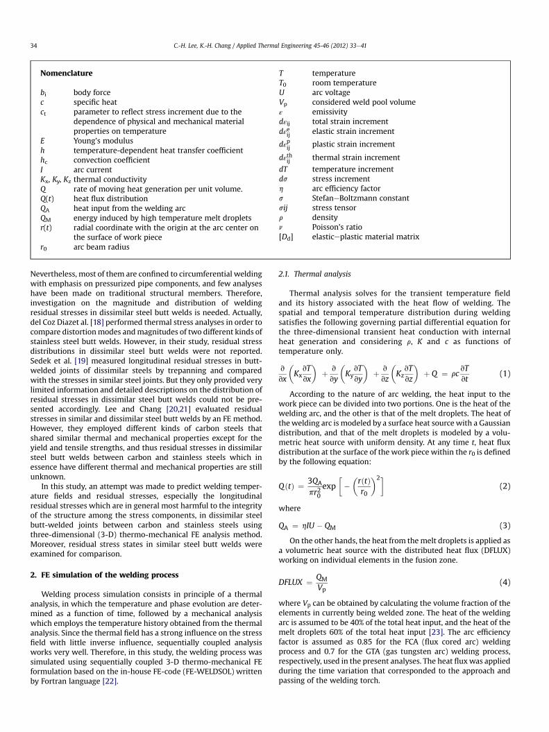
Table 1Welding conditions and process parameters.
Base Metal Welding process Current (A) Voltage (V) Speed (mm/s)
SM400 FCA 250 30 2.0SUS304 and dissimilar steels GTA 230 22 1.3
Fig. 4. Temperature-dependent thermo-physical constants of the materials: (a) SM400steel, (b) SUS304 steel.
Fig. 5. Temperature-dependent thermo-mechanical properties of SM400 steel andcorresponding weld metal.
C.-H. Lee, K.-H. Chang / Applied Thermal Engineering 45-46 (2012) 33e41 37
chosen for this study are SM400 carbon steel and SUS304austenitic stainless steel which have similar yield stress. SM400carbon steel joints were welded with DW-100 electrode of carbonsteel welding consumable, whilst SUS304 stainless steel joints anddissimilar steel joints were made using Y308L autenitic stainlesssteel weld filler [17,19]. Detailed information on the base materialsand weld metals is described in [21,26]. Practical welding condi-tions were adopted and the welding parameters chosen for thisanalysis are listed in Table 1 [30,31]. The 3-D FE mesh model usedin the simulation is shown in Fig. 3(b) with eight-noded iso-parametric solid elements. Four layers are used to discretize thecomputational domain. A fine grid is adopted in the weld regionand its vicinity in order to apply heat flux more accurately whenthe moving heat source passes the area at specific time steps andto capture the anticipated high stress gradients at the interfacebetween stainless steel filler and carbon steel base metal. Elementsize increases progressively with distance from the weld center-line. Mesh sensitivity study has been conducted to examine thedependence of FE mesh size on the accuracy of the analysis results.As a result, the present FE mesh with the smallest element size of0.5 mm (transverse) � 1.5 mm (thickness) � 25.0 mm (longitu-dinal) is considered to give sufficiently accurate results usinga reasonable amount of computer time and memory. Both theplates were included in the computational domain due to thedissymmetry of thermal and mechanical properties between thematerials used in the welding of dissimilar steels. In order tofacilitate data mapping between thermal and mechanical models,the same FE mesh refinement was used except for the elementtype and applied boundary conditions. For the thermal model, theelement type is one which has single degree of freedom,temperature, on its each node. For structural model, the elementtype is the other with three translational degrees of freedom ateach node. As the plate was not clamped during welding, noboundary conditions except those to prevent rigid body motion ofthe weld piece were applied.
In the FE simulation, temperature-dependent thermo-physical(e.g., thermal conductivity, specific heat and density) andmechanical properties (e.g., Young’s modulus, thermal expansioncoefficient, Poisson’s ratio and yield stress) of the base metals andweld materials were incorporated. Fig. 4(a) shows the physicalproperties at high temperatures of SM400 steel [20]. For SUS304steel, the thermal material properties are tabulated in Deng andMurakawa [26] and are shown in Fig. 4(b). It should be noted thatthe units in Fig. 4(a) and (b) are organized so that they can beshown on one graph for clarity. For the weld metals, temperature-dependent physical properties are assumed to be the same as thoseof corresponding base materials, respectively. Temperature-dependent thermo-mechanical properties of the base materialsare shown in Figs. 5 and 6, respectively [20,26]. Both the yield stressand elastic modulus are reduced to 5.0 MPa and 5.0 GPa, respec-tively, at the melting temperature to simulate low strength at hightemperatures [32]. For the weld metals, only the yield stress isdifferent from that of the corresponding base material as shown inthe figures, the other properties are almost the same as the cor-responding base metal. The physical and mechanical properties areassigned to the corresponding locations of the dissimilar steel butt-welded joints (base materials and weld metal).
The work hardening behavior induced by the thermal cyclicloading during welding in and around the welded joints should becarefully taken into account when a numerical method is utilized toaccurately predict welding residual stresses. A linear strain hard-ening of the carbon steel and corresponding weld metal wasassumed with the rate of 500 MPa for the temperature range20e700 �C and 20 MPa for the temperatures above 1000 �C [6]. Alinear transition between the hardening rate at 700 �C and that at1000 �C was assumed. For the stainless steel and its weld metal,temperature-dependent strain hardening rules were also used. Thestrain hardening rates of the base metal and the weld metal at hightemperatures are measured and given in [27], respectively. Fig. 7shows the temperature-dependent strain hardening rates of thecarbon and stainless steels.
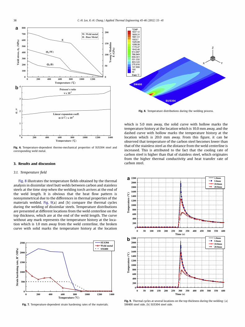
Fig. 6. Temperature-dependent thermo-mechanical properties of SUS304 steel andcorresponding weld metal.
Fig. 8. Temperature distributions during the welding process.
0
200
400
600
800
1000
1200
1400
1600
1800
2000
2200
0 50 100 150 200 250 300 350 400 450 500 550 600
Tem
pera
ture
(ºC
)
1.0mm5.0mm10.0mm20.0mm
a
C.-H. Lee, K.-H. Chang / Applied Thermal Engineering 45-46 (2012) 33e4138
3. Results and discussion
3.1. Temperature field
Fig. 8 illustrates the temperature fields obtained by the thermalanalysis in dissimilar steel butt welds between carbon and stainlesssteels at the time step when the welding torch arrives at the end ofthe weld length. It is obvious that the heat flow pattern isnonsymmetrical due to the differences in thermal properties of thematerials welded. Fig. 9(a) and (b) compare the thermal cyclesduring the welding of dissimilar steels. Temperature distributionsare presented at different locations from the weld centerline on thetop thickness, which are at the end of the weld length. The curvewithout any mark represents the temperature history at the loca-tion which is 1.0 mm away from the weld centerline, the brokencurve with solid marks the temperature history at the location
0
500
1000
1500
2000
2500
0 200 400 600 800 1000 1200 1400Temperature (oC)
Stra
in h
arde
ning
rat
e, H
' (M
Pa)
SUS304Weld metalSM400
Fig. 7. Temperature-dependent strain hardening rates of the materials.
which is 5.0 mm away, the solid curve with hollow marks thetemperature history at the locationwhich is 10.0 mm away, and thedashed curve with hollow marks the temperature history at thelocation which is 20.0 mm away. From this figure, it can beobserved that temperature of the carbon steel becomes lower thanthat of the stainless steel as the distance from theweld centerline isincreased. This is attributed to the fact that the cooling rate ofcarbon steel is higher than that of stainless steel, which originatesfrom the higher thermal conductivity and heat transfer rate ofcarbon steel.
Time (s)
0
200
400
600
800
1000
1200
1400
1600
1800
2000
2200
0 50 100 150 200 250 300 350 400 450 500 550 600Time (s)
Tem
pera
ture
(ºC
)
1.0mm5.0mm10.0mm20.0mm
b
Fig. 9. Thermal cycles at several locations on the top thickness during the welding: (a)SM400 steel side, (b) SUS304 steel side.
C.-H. Lee, K.-H. Chang / Applied Thermal Engineering 45-46 (2012) 33e41 39
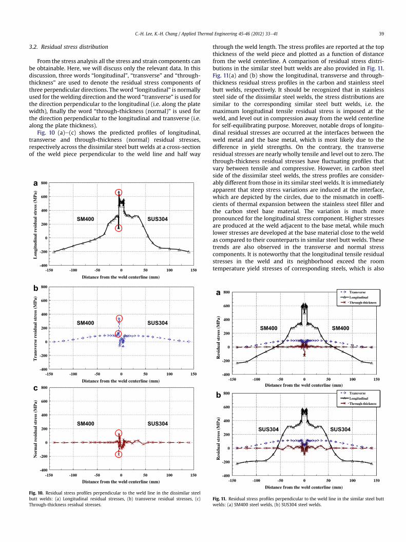
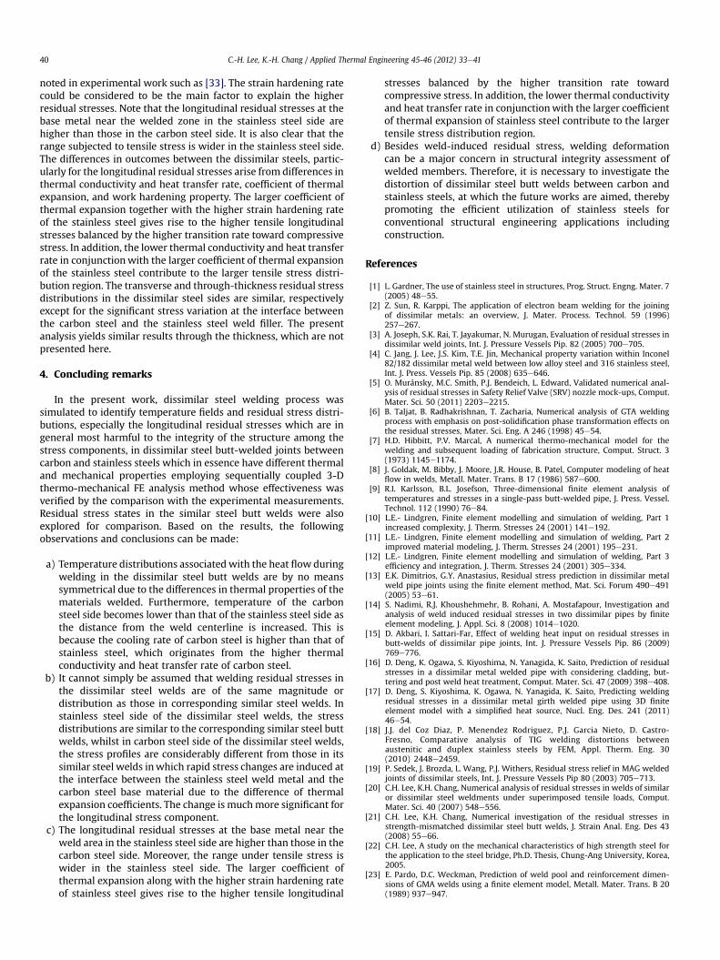
3.2. Residual stress distribution
From the stress analysis all the stress and strain components canbe obtainable. Here, we will discuss only the relevant data. In thisdiscussion, three words “longitudinal”, “transverse” and “through-thickness” are used to denote the residual stress components ofthree perpendicular directions. Theword “longitudinal” is normallyused for thewelding direction and theword “transverse” is used forthe direction perpendicular to the longitudinal (i.e. along the platewidth), finally the word “through-thickness (normal)” is used forthe direction perpendicular to the longitudinal and transverse (i.e.along the plate thickness).
Fig. 10 (a)e(c) shows the predicted profiles of longitudinal,transverse and through-thickness (normal) residual stresses,respectively across the dissimilar steel butt welds at a cross-sectionof the weld piece perpendicular to the weld line and half way
-400
-200
0
200
400
600
800
-150 -100 -50 0 50 100 150
Distance from the weld centerline (mm)
Lon
gitu
dina
l res
idua
l str
ess
(MP
a)
SUS304SM400
-400
-200
0
200
400
600
800
-150 -100 -50 0 50 100 150
Distance from the weld centerline (mm)
Tra
nsve
rse
resi
dual
str
ess
(MP
a)
SUS304SM400
-400
-200
0
200
400
600
800
-150 -100 -50 0 50 100 150
Distance from the weld centerline (mm)
Nor
mal
res
idua
l str
ess
(MP
a)
SUS304SM400
a
b
c
Fig. 10. Residual stress profiles perpendicular to the weld line in the dissimilar steelbutt welds: (a) Longitudinal residual stresses, (b) transverse residual stresses, (c)Through-thickness residual stresses.
through the weld length. The stress profiles are reported at the topthickness of the weld piece and plotted as a function of distancefrom the weld centerline. A comparison of residual stress distri-butions in the similar steel butt welds are also provided in Fig. 11.Fig. 11(a) and (b) show the longitudinal, transverse and through-thickness residual stress profiles in the carbon and stainless steelbutt welds, respectively. It should be recognized that in stainlesssteel side of the dissimilar steel welds, the stress distributions aresimilar to the corresponding similar steel butt welds, i.e. themaximum longitudinal tensile residual stress is imposed at theweld, and level out in compression away from the weld centerlinefor self-equilibrating purpose. Moreover, notable drops of longitu-dinal residual stresses are occurred at the interfaces between theweld metal and the base metal, which is most likely due to thedifference in yield strengths. On the contrary, the transverseresidual stresses are nearly wholly tensile and level out to zero. Thethrough-thickness residual stresses have fluctuating profiles thatvary between tensile and compressive. However, in carbon steelside of the dissimilar steel welds, the stress profiles are consider-ably different from those in its similar steel welds. It is immediatelyapparent that steep stress variations are induced at the interface,which are depicted by the circles, due to the mismatch in coeffi-cients of thermal expansion between the stainless steel filler andthe carbon steel base material. The variation is much morepronounced for the longitudinal stress component. Higher stressesare produced at the weld adjacent to the base metal, while muchlower stresses are developed at the base material close to the weldas compared to their counterparts in similar steel butt welds. Thesetrends are also observed in the transverse and normal stresscomponents. It is noteworthy that the longitudinal tensile residualstresses in the weld and its neighborhood exceed the roomtemperature yield stresses of corresponding steels, which is also
Fig. 11. Residual stress profiles perpendicular to the weld line in the similar steel buttwelds: (a) SM400 steel welds, (b) SUS304 steel welds.
C.-H. Lee, K.-H. Chang / Applied Thermal Engineering 45-46 (2012) 33e4140
noted in experimental work such as [33]. The strain hardening ratecould be considered to be the main factor to explain the higherresidual stresses. Note that the longitudinal residual stresses at thebase metal near the welded zone in the stainless steel side arehigher than those in the carbon steel side. It is also clear that therange subjected to tensile stress is wider in the stainless steel side.The differences in outcomes between the dissimilar steels, partic-ularly for the longitudinal residual stresses arise from differences inthermal conductivity and heat transfer rate, coefficient of thermalexpansion, and work hardening property. The larger coefficient ofthermal expansion together with the higher strain hardening rateof the stainless steel gives rise to the higher tensile longitudinalstresses balanced by the higher transition rate toward compressivestress. In addition, the lower thermal conductivity and heat transferrate in conjunctionwith the larger coefficient of thermal expansionof the stainless steel contribute to the larger tensile stress distri-bution region. The transverse and through-thickness residual stressdistributions in the dissimilar steel sides are similar, respectivelyexcept for the significant stress variation at the interface betweenthe carbon steel and the stainless steel weld filler. The presentanalysis yields similar results through the thickness, which are notpresented here.
4. Concluding remarks
In the present work, dissimilar steel welding process wassimulated to identify temperature fields and residual stress distri-butions, especially the longitudinal residual stresses which are ingeneral most harmful to the integrity of the structure among thestress components, in dissimilar steel butt-welded joints betweencarbon and stainless steels which in essence have different thermaland mechanical properties employing sequentially coupled 3-Dthermo-mechanical FE analysis method whose effectiveness wasverified by the comparison with the experimental measurements.Residual stress states in the similar steel butt welds were alsoexplored for comparison. Based on the results, the followingobservations and conclusions can be made:
a) Temperature distributions associatedwith the heat flow duringwelding in the dissimilar steel butt welds are by no meanssymmetrical due to the differences in thermal properties of thematerials welded. Furthermore, temperature of the carbonsteel side becomes lower than that of the stainless steel side asthe distance from the weld centerline is increased. This isbecause the cooling rate of carbon steel is higher than that ofstainless steel, which originates from the higher thermalconductivity and heat transfer rate of carbon steel.
b) It cannot simply be assumed that welding residual stresses inthe dissimilar steel welds are of the same magnitude ordistribution as those in corresponding similar steel welds. Instainless steel side of the dissimilar steel welds, the stressdistributions are similar to the corresponding similar steel buttwelds, whilst in carbon steel side of the dissimilar steel welds,the stress profiles are considerably different from those in itssimilar steel welds inwhich rapid stress changes are induced atthe interface between the stainless steel weld metal and thecarbon steel base material due to the difference of thermalexpansion coefficients. The change is muchmore significant forthe longitudinal stress component.
c) The longitudinal residual stresses at the base metal near theweld area in the stainless steel side are higher than those in thecarbon steel side. Moreover, the range under tensile stress iswider in the stainless steel side. The larger coefficient ofthermal expansion along with the higher strain hardening rateof stainless steel gives rise to the higher tensile longitudinal
stresses balanced by the higher transition rate towardcompressive stress. In addition, the lower thermal conductivityand heat transfer rate in conjunctionwith the larger coefficientof thermal expansion of stainless steel contribute to the largertensile stress distribution region.
d) Besides weld-induced residual stress, welding deformationcan be a major concern in structural integrity assessment ofwelded members. Therefore, it is necessary to investigate thedistortion of dissimilar steel butt welds between carbon andstainless steels, at which the future works are aimed, therebypromoting the efficient utilization of stainless steels forconventional structural engineering applications includingconstruction.
References
[1] L. Gardner, The use of stainless steel in structures, Prog. Struct. Engng. Mater. 7(2005) 48e55.
[2] Z. Sun, R. Karppi, The application of electron beam welding for the joiningof dissimilar metals: an overview, J. Mater. Process. Technol. 59 (1996)257e267.
[3] A. Joseph, S.K. Rai, T. Jayakumar, N. Murugan, Evaluation of residual stresses indissimilar weld joints, Int. J. Pressure Vessels Pip. 82 (2005) 700e705.
[4] C. Jang, J. Lee, J.S. Kim, T.E. Jin, Mechanical property variation within Inconel82/182 dissimilar metal weld between low alloy steel and 316 stainless steel,Int. J. Press. Vessels Pip. 85 (2008) 635e646.
[5] O. Muránsky, M.C. Smith, P.J. Bendeich, L. Edward, Validated numerical anal-ysis of residual stresses in Safety Relief Valve (SRV) nozzle mock-ups, Comput.Mater. Sci. 50 (2011) 2203e2215.
[6] B. Taljat, B. Radhakrishnan, T. Zacharia, Numerical analysis of GTA weldingprocess with emphasis on post-solidification phase transformation effects onthe residual stresses, Mater. Sci. Eng. A 246 (1998) 45e54.
[7] H.D. Hibbitt, P.V. Marcal, A numerical thermo-mechanical model for thewelding and subsequent loading of fabrication structure, Comput. Struct. 3(1973) 1145e1174.
[8] J. Goldak, M. Bibby, J. Moore, J.R. House, B. Patel, Computer modeling of heatflow in welds, Metall. Mater. Trans. B 17 (1986) 587e600.
[9] R.I. Karlsson, B.L. Josefson, Three-dimensional finite element analysis oftemperatures and stresses in a single-pass butt-welded pipe, J. Press. Vessel.Technol. 112 (1990) 76e84.
[10] L.E.- Lindgren, Finite element modelling and simulation of welding, Part 1increased complexity, J. Therm. Stresses 24 (2001) 141e192.
[11] L.E.- Lindgren, Finite element modelling and simulation of welding, Part 2improved material modeling, J. Therm. Stresses 24 (2001) 195e231.
[12] L.E.- Lindgren, Finite element modelling and simulation of welding, Part 3efficiency and integration, J. Therm. Stresses 24 (2001) 305e334.
[13] E.K. Dimitrios, G.Y. Anastasius, Residual stress prediction in dissimilar metalweld pipe joints using the finite element method, Mat. Sci. Forum 490e491(2005) 53e61.
[14] S. Nadimi, R.J. Khoushehmehr, B. Rohani, A. Mostafapour, Investigation andanalysis of weld induced residual stresses in two dissimilar pipes by finiteelement modeling, J. Appl. Sci. 8 (2008) 1014e1020.
[15] D. Akbari, I. Sattari-Far, Effect of welding heat input on residual stresses inbutt-welds of dissimilar pipe joints, Int. J. Pressure Vessels Pip. 86 (2009)769e776.
[16] D. Deng, K. Ogawa, S. Kiyoshima, N. Yanagida, K. Saito, Prediction of residualstresses in a dissimilar metal welded pipe with considering cladding, but-tering and post weld heat treatment, Comput. Mater. Sci. 47 (2009) 398e408.
[17] D. Deng, S. Kiyoshima, K. Ogawa, N. Yanagida, K. Saito, Predicting weldingresidual stresses in a dissimilar metal girth welded pipe using 3D finiteelement model with a simplified heat source, Nucl. Eng. Des. 241 (2011)46e54.
[18] J.J. del Coz Diaz, P. Menendez Rodriguez, P.J. Garcia Nieto, D. Castro-Fresno, Comparative analysis of TIG welding distortions betweenaustenitic and duplex stainless steels by FEM, Appl. Therm. Eng. 30(2010) 2448e2459.
[19] P. Sedek, J. Brozda, L. Wang, P.J. Withers, Residual stress relief in MAG weldedjoints of dissimilar steels, Int. J. Pressure Vessels Pip 80 (2003) 705e713.
[20] C.H. Lee, K.H. Chang, Numerical analysis of residual stresses in welds of similaror dissimilar steel weldments under superimposed tensile loads, Comput.Mater. Sci. 40 (2007) 548e556.
[21] C.H. Lee, K.H. Chang, Numerical investigation of the residual stresses instrength-mismatched dissimilar steel butt welds, J. Strain Anal. Eng. Des 43(2008) 55e66.
[22] C.H. Lee, A study on the mechanical characteristics of high strength steel forthe application to the steel bridge, Ph.D. Thesis, Chung-Ang University, Korea,2005.
[23] E. Pardo, D.C. Weckman, Prediction of weld pool and reinforcement dimen-sions of GMA welds using a finite element model, Metall. Mater. Trans. B 20(1989) 937e947.

C.-H. Lee, K.-H. Chang / Applied Thermal Engineering 45-46 (2012) 33e41 41
[24] M. Abid, M. Siddique, Numerical simulation to study the effect of tack weldsand root gap on welding deformations and residual stresses of a pipe-flangejoint, Int. J. Press. Vessels Pip 82 (2005) 860e871.
[25] B. Brickstad, B.L. Josefson, A parametric study of residual stresses in multi-pass butt-welded stainless steel pipes, Int. J. Pressure Vessels Pip 75 (1998)11e25.
[26] D. Deng, H. Murakawa, Numerical simulation of temperature field andresidual stress in multi-pass welds in stainless steel pipe and comparisonwith experimental measurements, Comput. Mater. Sci. 37 (2006)269e277.
[27] D. Deng, H. Murakawa, W. Liang, Numerical and experimental investigationson welding residual stress in multi-pass butt-welded austenitic stainless steelpipe, Comput. Mater. Sci. 42 (2008) 234e244.
[28] K.J. Bathe, Finite Element Procedures, Prentice Hall, 1996.[29] M. Seyyedian, S.H. Amini, M. Haghpanahi, Study on the Effect of Thickness on
Residual Stresses in Butt Welding of SUS304 Plates, IIW ICAWAT, Singapore,2009, 195e200.
[30] S.H. Lee, K.H. Chang, Prediction of stress and deformation by 2D and 3D-FEManalysis and its accuracy, J. COSEIK 17 (2004) 365e375.
[31] I. Sattari-Far, Y. Javadi, Influence of welding sequence on welding distortionsin pipes, Int. J. Pressure Vessels Pip 85 (2008) 265e274.
[32] Z. Barsoum, Residual stress analysis and fatigue of multi-pass welded tubularstructures, Eng. Fail. Anal. 15 (2008) 863e874.
[33] A. Paradowska, J.W.H. Price, R. Ibrahim, T. Finlayson, A neutron diffractionstudy of residual stress due to welding, J. Mater. Process. Technol. 164-165(2005) 1099e1105.