Embed Size (px)
Citation preview
General rights Copyright and moral rights for the publications made accessible in the public portal are retained by the authors and/or other copyright owners and it is a condition of accessing publications that users recognise and abide by the legal requirements associated with these rights.
Users may download and print one copy of any publication from the public portal for the purpose of private study or research.
You may not further distribute the material or use it for any profit-making activity or commercial gain
You may freely distribute the URL identifying the publication in the public portal If you believe that this document breaches copyright please contact us providing details, and we will remove access to the work immediately and investigate your claim.
Downloaded from orbit.dtu.dk on: Mar 11, 2020
Temperature effects of Mach-Zehnder interferometer using a liquid crystal-filled fiber
Ho, Bo-Yan; Su, Hsien-Pin; Tseng, Yu-Pei; Wu, Shin-Tson; Hwang, Shug-June
Published in:Optics Express
Link to article, DOI:10.1364/OE.23.033588
Publication date:2015
Document VersionPublisher's PDF, also known as Version of record
Link back to DTU Orbit
Citation (APA):Ho, B-Y., Su, H-P., Tseng, Y-P., Wu, S-T., & Hwang, S-J. (2015). Temperature effects of Mach-Zehnderinterferometer using a liquid crystal-filled fiber. Optics Express, 23(26), 33588-33596.https://doi.org/10.1364/OE.23.033588
Temperature effects of Mach-Zehnder interferometer using a liquid crystal-filled fiber Bo-Yan Ho,1 Hsien-Pin Su,1 Yu-Pei Tseng,2 Shin-Tson Wu,3 and Shug-June Hwang1,3,*
1Department of Electro-Optical Engineering, National United University, Maio-Li, 360, Taiwan 2Department of Photonics Engineering, Technical University of Denmark, Roskilde, 4000, Denmark
3College of Optics and Photonics, University of Central Florida, Orlando, Florida 32816, USA *[email protected]
Abstract: We demonstrated a simple and cost-effective method to fabricate all fiber Mach–Zehnder interferometer (MZI) based on cascading a short section of liquid crystal (LC)-filled hollow-optic fiber (HOF) between two single mode fibers by using automatically splicing technique. The transmission spectra of the proposed MZI with different LC-infiltrated length were measured and the temperature-induced wavelength shifts of the interference fringes were recorded. Both blue shift and red shift were observed, depending the temperature range. Based on our experimental results, interference fringe was observed with a maximum interferometric contrast over 35dB. The temperature-induced resonant wavelength blue-shifts 70.4 nm for the MZI with an LC length of 9.79 mm and the wavelength temperature sensitivity of −1.55 nm/°C is easily achieved as the temperature increases from 25°C to 77°C.
©2015 Optical Society of America
OCIS codes: (060.2280) Fiber design and fabrication; (230.3720) Liquid-crystal devices; (230.3990) Micro-optical devices.
References and links
1. P. Antunes, A. M. Rocha, H. Lima, H. Varum, and P. S. André, “Thin bonding wires temperature measurementusing optical fiber sensors,” Measurement 44(3), 554–558 (2011).
2. É. Pinet, “Pressure measurement with fiber-optic sensors: commercial technologies and applications,” Proc. SPIE 7753, 775304 (2011).
3. H. Ahmad, M. Yasin, K. Thambiratnam, and S. W. Harun, “Fiber optic displacement sensor for micro-thickness measurement,” Sensor Rev. 32(3), 230–235 (2012).
4. Y. Cao, H. Liu, Z. Tong, and S. Yuan, “Simultaneous measurement of temperature and microdisplacement based on a Mach–Zehnder interferometer cascaded with a fiber Bragg grating,” Opt. Eng. 54(6), 066101 (2015).
5. J. Yang, L. Jiang, S. Wang, Q. Chen, B. Li, and H. Xiao, “Highly sensitive refractive index optical fiber sensors fabricated by a femtosecond laser,” IEEE Photonics J. 3(6), 1189–1197 (2011).
6. Q. Shi, B. Peng, D. Chen, S. Fu, and H. Dai, “A new refractive index sensor based on Mach-Zehnder interferometer fabricated by two cascaded single-mode fiber corners,” Proc. SPIE 9274, 92741C (2014).
7. S. Zhang, W. Zhang, P. Geng, and L. Wang, “A Mach–Zehnder interferometer constructed using lateral offset and a long period fiber grating for two-dimensional bending vector sensing,” J. Opt. 16(1), 015501 (2014).
8. J. H. Lim, H. S. Jang, K. S. Lee, J. C. Kim, and B. H. Lee, “Mach-Zehnder interferometer formed in a photonic crystal fiber based on a pair of long-period fiber gratings,” Opt. Lett. 29(4), 346–348 (2004).
9. J. Yang, L. Jiang, S. Wang, B. Li, M. Wang, H. Xiao, Y. Lu, and H. Tsai, “High sensitivity of taper-based Mach-Zehnder interferometer embedded in a thinned optical fiber for refractive index sensing,” Appl. Opt. 50(28),5503–5507 (2011).
10. R. Yang, Y. S. Yu, Y. Xue, C. Chen, Q. D. Chen, and H. B. Sun, “Single S-tapered fiber Mach-Zehnder interferometers,” Opt. Lett. 36(23), 4482–4484 (2011).
11. P. Lu, J. Harris, Y. Xu, Y. Lu, L. Chen, and X. Bao, “Simultaneous refractive index and temperature measurements using a tapered bend-resistant fiber interferometer,” Opt. Lett. 37(22), 4567–4569 (2012).
12. J. Zhou, C. Liao, Y. Wang, G. Yin, X. Zhong, K. Yang, B. Sun, G. Wang, and Z. Li, “Simultaneousmeasurement of strain and temperature by employing fiber Mach-Zehnder interferometer,” Opt. Express 22(2),1680–1686 (2014).
13. W. Ding, Y. Jiang, R. Gao, Z. Wang, and Y. Liu, “An in-line photonic crystal fibre-based Mach–Zehnder interferometer with temperature compensation,” Meas. Sci. Technol. 25(10), 107002 (2014).
14. W. Talataisong, D. N. Wang, R. Chitaree, C. R. Liao, and C. Wang, “Fiber in-line Mach-Zehnder interferometer based on an inner air-cavity for high-pressure sensing,” Opt. Lett. 40(7), 1220–1222 (2015).
15. M. Park, S. Lee, W. Ha, D.-K. Kim, W. Shin, I.-B. Sohn, and K. Oh, “Ultracompact intrinsic micro air-cavity fiber mach–zehnder interferometer,” IEEE Photonics Technol. Lett. 21(15), 1027–1029 (2009).
#250490 Received 21 Sep 2015; revised 17 Nov 2015; accepted 14 Dec 2015; published 21 Dec 2015 © 2015 OSA 28 Dec 2015 | Vol. 23, No. 26 | DOI:10.1364/OE.23.033588 | OPTICS EXPRESS 33588
16. D. K. Yang and S. T. Wu, Fundamentals of Liquid Crystal Devices, 2nd ed. (Wiley, 2014). 17. F. Du, Y.-Q. Lu, and S.-T. Wu, “Electrically tunable liquid-crystal photonic crystal fiber,” Appl. Phys. Lett.
85(12), 2181–2183 (2004). 18. A. Lorenz, R. Schuhmann, and H. S. Kitzerow, “Infiltrated photonic crystal fiber: experiments and liquid crystal
scattering model,” Opt. Express 18(4), 3519–3530 (2010). 19. G. Zito and S. Pissadakis, “Holographic polymer-dispersed liquid crystal Bragg grating integrated inside a solid
core photonic crystal fiber,” Opt. Lett. 38(17), 3253–3256 (2013). 20. K. R. Khan, S. Bidnyk, and T. J. Hall, “Tunable all optical switch implemented in a liquid crystal filled dual-core
photonic crystal fiber,” Prog. Electromag. Res. M 22, 179–189 (2012). 21. T. Alkeskjold, J. Lægsgaard, A. Bjarklev, D. Hermann, A. Anawati, J. Broeng, J. Li, and S. T. Wu, “All-optical
modulation in dye-doped nematic liquid crystal photonic bandgap fibers,” Opt. Express 12(24), 5857–5871 (2004).
22. J. Li, S. Gauzia, and S.-T. Wu, “High temperature-gradient refractive index liquid crystals,” Opt. Express 12(9), 2002–2010 (2004).
23. J. I. S. Handbook, 33 Glass, Japanese Stand. Assoc., Tokyo, Japan, 2010. 24. S. Weiss and G. Ahlers, “Nematic–isotropic phase transition in turbulent thermal convection,” J. Fluid Mech.
737, 308–328 (2013).
1. Introduction
Fiber-optic devices exhibit several inherent advantages, such as compact size, simple fabrication, and immunity to electromagnetic interference. Thus, they are attractive for various sensing applications, including temperature [1], strain [2], displacement [3,4], and refractive index [5,6]. Among many promising photonic devices, fiber -based Mach–Zehnder interferometer (MZI) stands out because of its simplicity, compactness, relative simple fabrication and high resolution. To achieve a MZI device in a single fiber, a relative phase difference of two beams originated from the same laser light is essential, which can be realized by allowing the two beams traveling in different paths. There are many ways to realize an in- fiber MZI. A common method is to induce and recombine the core mode and cladding modes of a SMF by using double fiber corners [6], long-period fiber grating (LPFG) [7,8], optical fiber taper [9–11], misalign spliced joint [12], microstructure collapsing on a photonic crystal fiber [13], imbedded micro air-cavity in fiber [14,15], etc. However, these techniques require complicated process or expensive fabrication apparatus, which knowingly limit their practical applications. Moreover, the sensitivity of the reported MZIs is not yet completely satisfactory with respect to an external field, e.g. temperature, electric field, or magnetic field.
Liquid crystal (LC) is a useful electro-optic medium and has been widely used in display and photonic devices [16] because its refractive index can be changed by the temperature or by a relatively low voltage. Several potentially useful photonic devices combining LCs and fiber technologies have been proposed [17–22].
In this paper, we experimentally demonstrate a compact all-fiber MZI device by splicing a section of LC-filled hollow optic fiber (HOF) between two single mode fibers (SMFs), in which two ultra-abrupt tapers near the spliced joints are constructed by a fusion splicer. The two tapering sections excite the cladding modes of a hollow core fiber at the first SMF-HOF interface, and combine the interfering signal of the core mode and cladding modes into the lead-out SMF. The interference properties of the proposed MZI were measured by the optical spectrum analyzer (OSA), and its thermal-optic properties were experimentally studied and discussed. The transmission spectrum of such a MZI fiber can be thermally tuned by controlling the device temperature. A unique feature of LC is that its temperature dependent refractive index is quite large and the temperature gradient can be negative, zero, or positive, depending on the operating temperature. Using our LC-infiltrated MZI, we have achieved a temperature sensitivity/tuning capability of ~−1.55 nm/°C in the temperature range between 25°C and 77°C. This sensitivity is about 30X higher than that of previously developed MZIs with a misalignment-spliced joint (51 pm/°C) [12] and micro air-cavity (44.1 pm/°C) [15]. Thus, our LC-based MZI has potential applications as a high wavelength-tunable photonic device or a high sensitivity temperature sensor.
#250490 Received 21 Sep 2015; revised 17 Nov 2015; accepted 14 Dec 2015; published 21 Dec 2015 © 2015 OSA 28 Dec 2015 | Vol. 23, No. 26 | DOI:10.1364/OE.23.033588 | OPTICS EXPRESS 33589
2. Operation principle
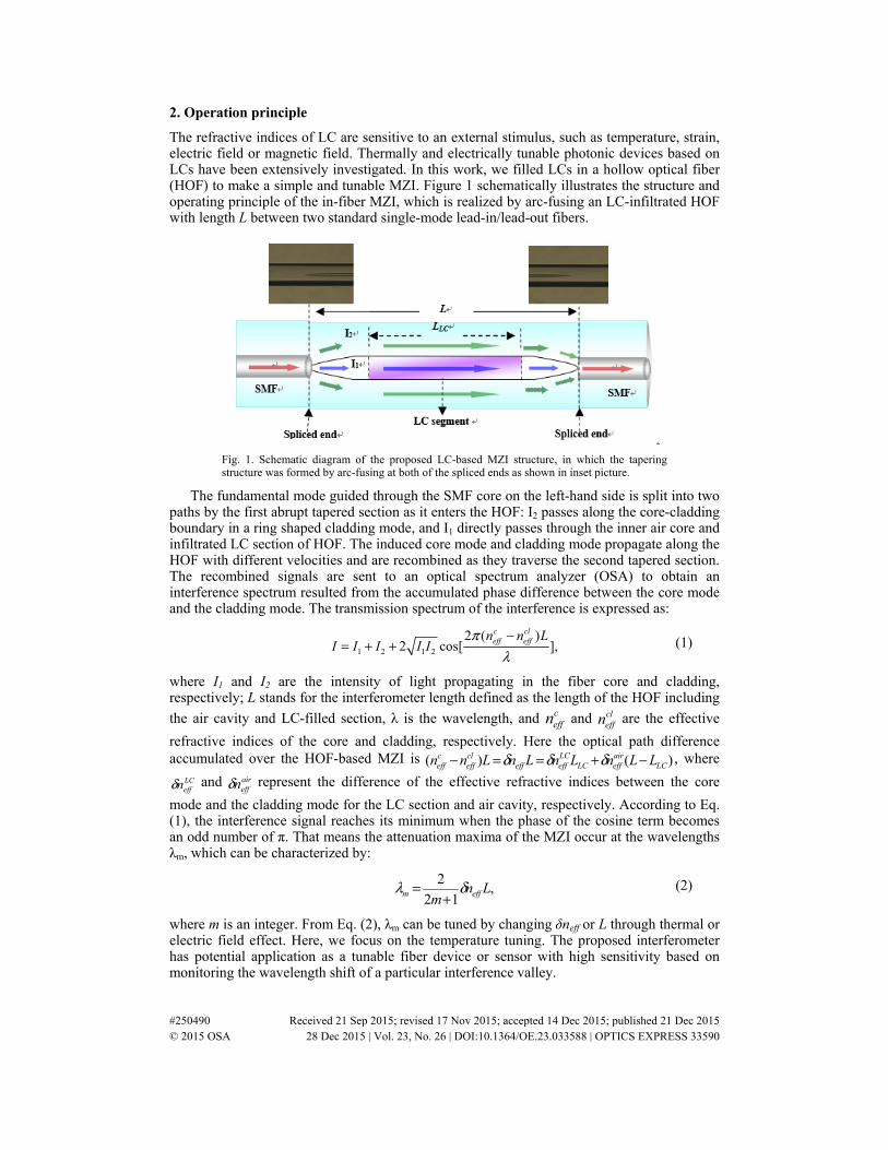
The refractive indices of LC are sensitive to an external stimulus, such as temperature, strain, electric field or magnetic field. Thermally and electrically tunable photonic devices based on LCs have been extensively investigated. In this work, we filled LCs in a hollow optical fiber (HOF) to make a simple and tunable MZI. Figure 1 schematically illustrates the structure and operating principle of the in-fiber MZI, which is realized by arc-fusing an LC-infiltrated HOF with length L between two standard single-mode lead-in/lead-out fibers.
Fig. 1. Schematic diagram of the proposed LC-based MZI structure, in which the tapering structure was formed by arc-fusing at both of the spliced ends as shown in inset picture.
The fundamental mode guided through the SMF core on the left-hand side is split into two paths by the first abrupt tapered section as it enters the HOF: I2 passes along the core-cladding boundary in a ring shaped cladding mode, and I1 directly passes through the inner air core and infiltrated LC section of HOF. The induced core mode and cladding mode propagate along the HOF with different velocities and are recombined as they traverse the second tapered section. The recombined signals are sent to an optical spectrum analyzer (OSA) to obtain an interference spectrum resulted from the accumulated phase difference between the core mode and the cladding mode. The transmission spectrum of the interference is expressed as:
1 2 1 2
2 ( )2 cos[ ],
c cleff effn n L
I I I I Iπ
λ−
= + + (1)
where I1 and I2 are the intensity of light propagating in the fiber core and cladding, respectively; L stands for the interferometer length defined as the length of the HOF including
the air cavity and LC-filled section, λ is the wavelength, and ceffn and cl
effn are the effective
refractive indices of the core and cladding, respectively. Here the optical path difference accumulated over the HOF-based MZI is )()( LC
aireffLC
LCeffeff
cleff
ceff LLnLnLnLnn −+==− δδδ , where
LCeffnδ and air
effnδ represent the difference of the effective refractive indices between the core
mode and the cladding mode for the LC section and air cavity, respectively. According to Eq. (1), the interference signal reaches its minimum when the phase of the cosine term becomes an odd number of π. That means the attenuation maxima of the MZI occur at the wavelengths λm, which can be characterized by:
,12
2Ln
m effm δλ+
= (2)
where m is an integer. From Eq. (2), λm can be tuned by changing δneff or L through thermal or electric field effect. Here, we focus on the temperature tuning. The proposed interferometer has potential application as a tunable fiber device or sensor with high sensitivity based on monitoring the wavelength shift of a particular interference valley.
#250490 Received 21 Sep 2015; revised 17 Nov 2015; accepted 14 Dec 2015; published 21 Dec 2015 © 2015 OSA 28 Dec 2015 | Vol. 23, No. 26 | DOI:10.1364/OE.23.033588 | OPTICS EXPRESS 33590
To investigate the thermal-optic tuning or sensing capability of the LC-based MZI, we measured the spectral shift induced by the temperature. Since the refractive index of LC molecules in the hollow core is much more sensitive to the temperature than that of the air cavity, the sensitivity of attenuation peak wavelength with respect to the temperature change can be approximated from Eq. (2) as
,)()(
12
2
∂−∂+
∂∂+
∂∂
+=
∂∂
T
LLn
T
Ln
T
nL
mTLCair
effLCLC
eff
LCeff
LCm δδ
δλ (3)
where T is the temperature, and Tn LCeff ∂∂ )(δ and TLLC ∂∂ )( are the thermal-optic effect and
thermal expansion property of the LC fiber material, respectively. From Eq. (3), it is clear that the temperature sensitivity of MZI is mainly contributed by the difference of the thermo-optic dependence of the fiber LC-core, silica cladding, and thermal expansion coefficient of the air cavity and LC segments. Because the effective refractive index of LC core ( LC
effn ) is much
more sensitive than that of silica cladding ( cleffn ), the thermo-optic effect of the LC fiber is
primarily governed by the temperature gradient of refractive index of LC material, i.e. TnTn LC
effLCeff ∂∂≈∂∂ )()(δ .
3. Experimental
To make an LC-based fiber, we used a hollow optical fiber TSP010150 (Polymicro). The inner and outer diameters of the HOF measured by SEM were 8.5 μm and 125 μm, respectively. The employed liquid crystal was RDP-98995 (DIC Corp.) with refractive index no = 1.484 and ne = 1.575 at λ = 589 nm and 25°C, and its clearing temperature Tc is 90.5°C. We infiltrated the LC into the hollow fiber for a desired length by capillary flow. After finishing the infiltration of LC sector, the two end faces of the HOF were spliced to two SMFs by using a commercial fusion splicer. By adjusting the fusion-splicing condition, one can easily collapse air hole at both splicing ends of the HOF, and then an abrupt tapering structure can be achieved near two spliced joints as the inset photos show in Fig. 1. As mentioned above, the tapered sections function as a beam splitter and combiner, which induce the cladding modes at the front end and recombine the core-mode light and the cladding-mode light into the second SMF to generate the interference signals.
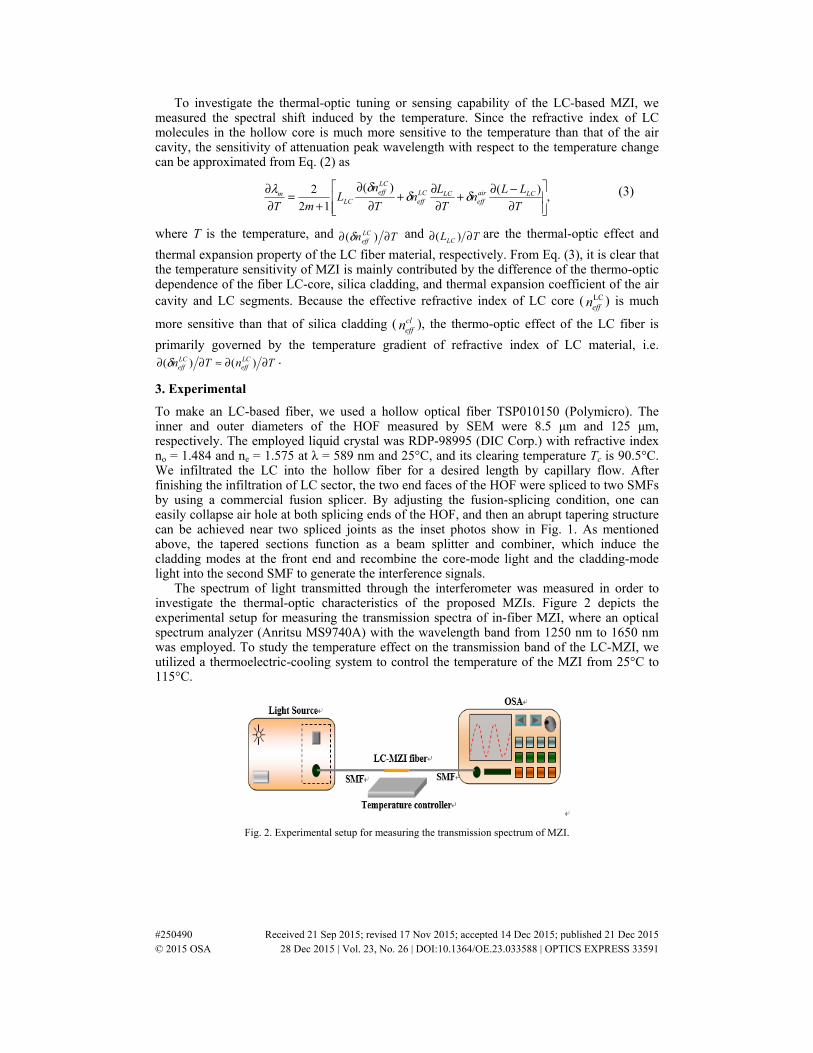
The spectrum of light transmitted through the interferometer was measured in order to investigate the thermal-optic characteristics of the proposed MZIs. Figure 2 depicts the experimental setup for measuring the transmission spectra of in-fiber MZI, where an optical spectrum analyzer (Anritsu MS9740A) with the wavelength band from 1250 nm to 1650 nm was employed. To study the temperature effect on the transmission band of the LC-MZI, we utilized a thermoelectric-cooling system to control the temperature of the MZI from 25°C to 115°C.
Fig. 2. Experimental setup for measuring the transmission spectrum of MZI.
#250490 Received 21 Sep 2015; revised 17 Nov 2015; accepted 14 Dec 2015; published 21 Dec 2015 © 2015 OSA 28 Dec 2015 | Vol. 23, No. 26 | DOI:10.1364/OE.23.033588 | OPTICS EXPRESS 33591
4. Device characterization
4.1 MZI properties
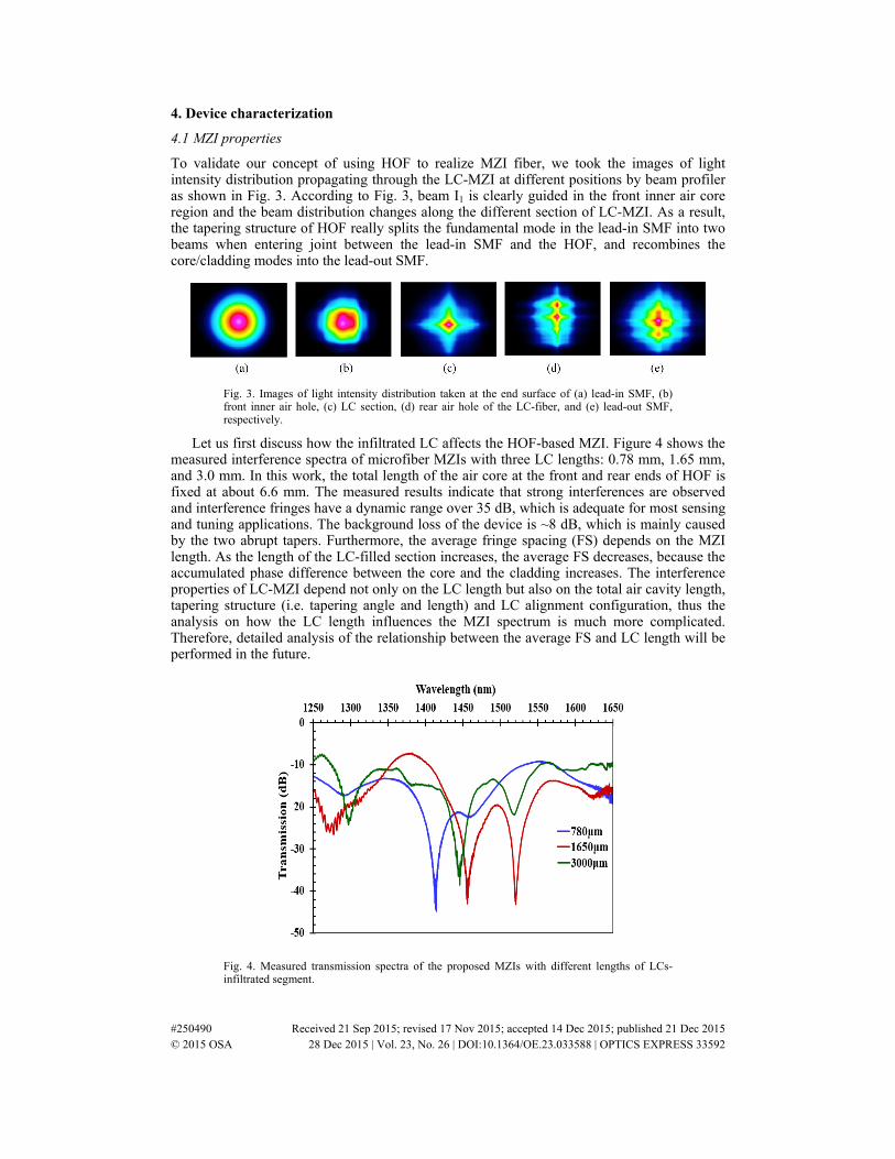
To validate our concept of using HOF to realize MZI fiber, we took the images of light intensity distribution propagating through the LC-MZI at different positions by beam profiler as shown in Fig. 3. According to Fig. 3, beam I1 is clearly guided in the front inner air core region and the beam distribution changes along the different section of LC-MZI. As a result, the tapering structure of HOF really splits the fundamental mode in the lead-in SMF into two beams when entering joint between the lead-in SMF and the HOF, and recombines the core/cladding modes into the lead-out SMF.
Fig. 3. Images of light intensity distribution taken at the end surface of (a) lead-in SMF, (b) front inner air hole, (c) LC section, (d) rear air hole of the LC-fiber, and (e) lead-out SMF, respectively.
Let us first discuss how the infiltrated LC affects the HOF-based MZI. Figure 4 shows the measured interference spectra of microfiber MZIs with three LC lengths: 0.78 mm, 1.65 mm, and 3.0 mm. In this work, the total length of the air core at the front and rear ends of HOF is fixed at about 6.6 mm. The measured results indicate that strong interferences are observed and interference fringes have a dynamic range over 35 dB, which is adequate for most sensing and tuning applications. The background loss of the device is ~8 dB, which is mainly caused by the two abrupt tapers. Furthermore, the average fringe spacing (FS) depends on the MZI length. As the length of the LC-filled section increases, the average FS decreases, because the accumulated phase difference between the core and the cladding increases. The interference properties of LC-MZI depend not only on the LC length but also on the total air cavity length, tapering structure (i.e. tapering angle and length) and LC alignment configuration, thus the analysis on how the LC length influences the MZI spectrum is much more complicated. Therefore, detailed analysis of the relationship between the average FS and LC length will be performed in the future.
Fig. 4. Measured transmission spectra of the proposed MZIs with different lengths of LCs-infiltrated segment.
#250490 Received 21 Sep 2015; revised 17 Nov 2015; accepted 14 Dec 2015; published 21 Dec 2015 © 2015 OSA 28 Dec 2015 | Vol. 23, No. 26 | DOI:10.1364/OE.23.033588 | OPTICS EXPRESS 33592
4.2 Thermal characteristics
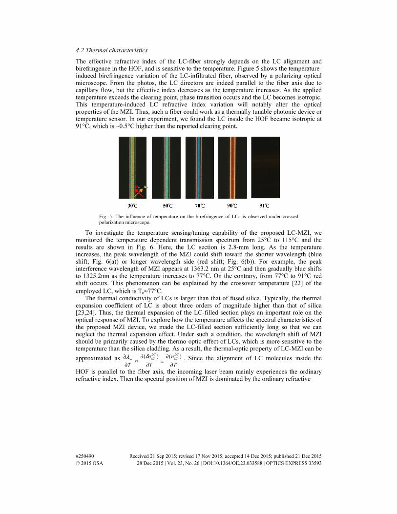
The effective refractive index of the LC-fiber strongly depends on the LC alignment and birefringence in the HOF, and is sensitive to the temperature. Figure 5 shows the temperature-induced birefringence variation of the LC-infiltrated fiber, observed by a polarizing optical microscope. From the photos, the LC directors are indeed parallel to the fiber axis due to capillary flow, but the effective index decreases as the temperature increases. As the applied temperature exceeds the clearing point, phase transition occurs and the LC becomes isotropic. This temperature-induced LC refractive index variation will notably alter the optical properties of the MZI. Thus, such a fiber could work as a thermally tunable photonic device or temperature sensor. In our experiment, we found the LC inside the HOF became isotropic at 91°C, which is ~0.5°C higher than the reported clearing point.
Fig. 5. The influence of temperature on the birefringence of LCs is observed under crossed polarization microscope.
To investigate the temperature sensing/tuning capability of the proposed LC-MZI, we monitored the temperature dependent transmission spectrum from 25°C to 115°C and the results are shown in Fig. 6. Here, the LC section is 2.8-mm long. As the temperature increases, the peak wavelength of the MZI could shift toward the shorter wavelength (blue shift; Fig. 6(a)) or longer wavelength side (red shift; Fig. 6(b)). For example, the peak interference wavelength of MZI appears at 1363.2 nm at 25°C and then gradually blue shifts to 1325.2nm as the temperature increases to 77°C. On the contrary, from 77°C to 91°C red shift occurs. This phenomenon can be explained by the crossover temperature [22] of the employed LC, which is To≈77°C.
The thermal conductivity of LCs is larger than that of fused silica. Typically, the thermal expansion coefficient of LC is about three orders of magnitude higher than that of silica [23,24]. Thus, the thermal expansion of the LC-filled section plays an important role on the optical response of MZI. To explore how the temperature affects the spectral characteristics of the proposed MZI device, we made the LC-filled section sufficiently long so that we can neglect the thermal expansion effect. Under such a condition, the wavelength shift of MZI should be primarily caused by the thermo-optic effect of LCs, which is more sensitive to the temperature than the silica cladding. As a result, the thermal-optic property of LC-MZI can be
approximated as T
n
T
n
T
LCeff
LCeffm
∂∂
≅∂
∂∝
∂∂ )()(δλ . Since the alignment of LC molecules inside the
HOF is parallel to the fiber axis, the incoming laser beam mainly experiences the ordinary refractive index. Then the spectral position of MZI is dominated by the ordinary refractive
#250490 Received 21 Sep 2015; revised 17 Nov 2015; accepted 14 Dec 2015; published 21 Dec 2015 © 2015 OSA 28 Dec 2015 | Vol. 23, No. 26 | DOI:10.1364/OE.23.033588 | OPTICS EXPRESS 33593
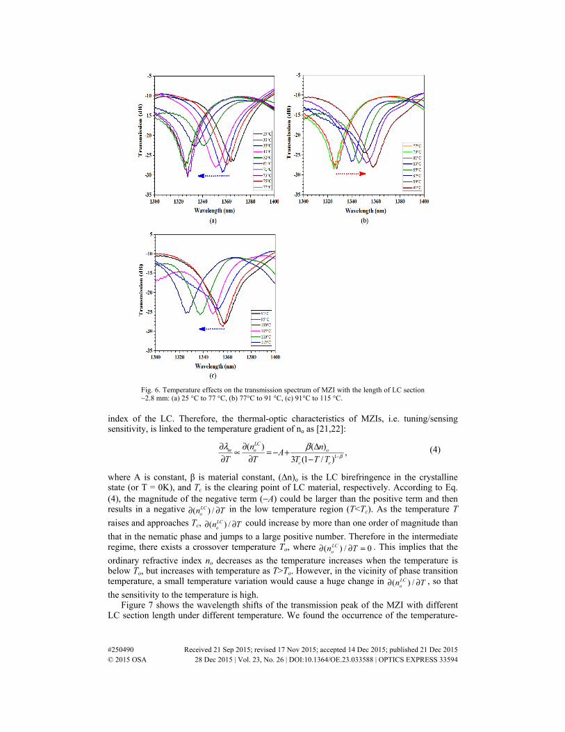
Fig. 6. Temperature effects on the transmission spectrum of MZI with the length of LC section ~2.8 mm: (a) 25 °C to 77 °C, (b) 77°C to 91 °C, (c) 91°C to 115 °C.
index of the LC. Therefore, the thermal-optic characteristics of MZIs, i.e. tuning/sensing sensitivity, is linked to the temperature gradient of no as [21,22]:
1
( ) ( ),
3 (1 / )
LCm o o
c c
n nA
T T T T T βλ β
−
∂ ∂ Δ∝ = − +∂ ∂ −
(4)
where A is constant, β is material constant, (Δn)o is the LC birefringence in the crystalline state (or T = 0K), and Tc is the clearing point of LC material, respectively. According to Eq. (4), the magnitude of the negative term (−A) could be larger than the positive term and then results in a negative ( ) /LC
on T∂ ∂ in the low temperature region (T<Tc). As the temperature T
raises and approaches Tc, ( ) /LCon T∂ ∂ could increase by more than one order of magnitude than
that in the nematic phase and jumps to a large positive number. Therefore in the intermediate regime, there exists a crossover temperature To, where ( ) / 0LC
on T∂ ∂ = . This implies that the
ordinary refractive index no decreases as the temperature increases when the temperature is below To, but increases with temperature as T>To. However, in the vicinity of phase transition temperature, a small temperature variation would cause a huge change in ( ) /LC
on T∂ ∂ , so that
the sensitivity to the temperature is high. Figure 7 shows the wavelength shifts of the transmission peak of the MZI with different
LC section length under different temperature. We found the occurrence of the temperature-
#250490 Received 21 Sep 2015; revised 17 Nov 2015; accepted 14 Dec 2015; published 21 Dec 2015 © 2015 OSA 28 Dec 2015 | Vol. 23, No. 26 | DOI:10.1364/OE.23.033588 | OPTICS EXPRESS 33594
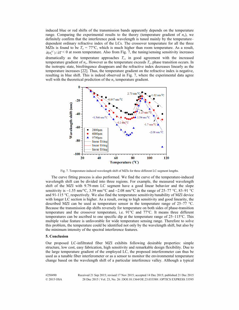
induced blue or red shifts of the transmission bands apparently depends on the temperature range. Comparing the experimental results to the theory (temperature gradient of no), we definitely confirm that the interference peak wavelength is tuned mainly by the temperature–dependent ordinary refractive index of the LCs. The crossover temperature for all the three MZIs is found to be To = 77°C, which is much higher than room temperature. As a result,
( ) /LCon T∂ ∂ < 0 at room temperature. Also from Fig. 7, the tuning/sensing sensitivity increases
dramatically as the temperature approaches Tc, in good agreement with the increased temperature gradient of no. However as the temperature exceeds Tc, phase transition occurs. In the isotropic state, birefringence disappears and the refractive index decreases linearly as the temperature increases [22]. Thus, the temperature gradient on the refractive index is negative, resulting in blue shift. This is indeed observed in Fig. 7, where the experimental data agree well with the theoretical prediction of the no temperature gradient.
Fig. 7. Temperature-induced wavelength shift of MZIs for three different LC-segment lengths.
The curve fitting process is also performed. We find the curve of the temperature-induced wavelength shift can be divided into three regions. For example, the measured wavelength shift of the MZI with 9.79-mm LC segment have a good linear behavior and the slope sensitivity is −1.55 nm/°C, 3.59 nm/°C and −2.08 nm/°C in the range of 25–77 °C, 83–91 °C and 91-115 °C, respectively. We also find the temperature sensitivity/tunability of MZI device with longer LC section is higher. As a result, owing to high sensitivity and good linearity, the described MZI can be used as temperature sensor in the temperature range of 25–77 °C. Because the transmission dip shifts reversely for temperature on both sides of phase-transition temperature and the crossover temperature, i.e. 91°C and 77°C. It means three different temperatures can be ascribed to one specific dip at the temperature range of 25–115°C. This multiple value feature is unfavorable for wide temperature sensing range. Therefore to solve this problem, the temperature could be identified not only by the wavelength shift, but also by the minimum intensity of the spectral interference features.
5. Conclusion
Our proposed LC-infiltrated fiber MZI exhibits following desirable properties: simple structure, low cost, easy fabrication, high sensitivity and remarkable design flexibility. Due to the large temperature gradient of the employed LC, the proposed interferometer can thus be used as a tunable fiber interferometer or as a sensor to monitor the environmental temperature change based on the wavelength shift of a particular interference valley. Although a typical
#250490 Received 21 Sep 2015; revised 17 Nov 2015; accepted 14 Dec 2015; published 21 Dec 2015 © 2015 OSA 28 Dec 2015 | Vol. 23, No. 26 | DOI:10.1364/OE.23.033588 | OPTICS EXPRESS 33595
fusion splice has a certain tensile strength and will not break during normal handling, the mechanical strength of the splicing points is a critical issue. To protect the splicing joint, we could use a heat shrink tubing, silicone gel and/or mechanical crimp protector. The proposed compact LC-MZI can also be used as a sensor to detect the bending, strain, and refractive index of an object.
Acknowledgments
The authors are indebted to the financial support from Ministry of Science and Technology of Taiwan under contract No. MOST 103-2221-E-239 −003, Giantplus Tech. Company for providing the liquid crystal material, and technical assistance from Prof. Nan-Kung Chen of the National United University, Taiwan.
#250490 Received 21 Sep 2015; revised 17 Nov 2015; accepted 14 Dec 2015; published 21 Dec 2015 © 2015 OSA 28 Dec 2015 | Vol. 23, No. 26 | DOI:10.1364/OE.23.033588 | OPTICS EXPRESS 33596