Embed Size (px)
Citation preview

Read carefully before installation, commissioning and operation
Temperature Difference Controller TDC 3
Installation and operating instructions
TDC 3Temperature-Difference-Controller

ContentA.1 EC declaration of conformity 3A.2 General instructions 3A.3 Explanation of symbols 3A.4 EC declaration of conformity 4A.5 Warranty and liability 4
B.1 Specifi cations 5B.2 About the controller 6B.3 Scope of supply 6B.4 Disposal and pollutants 6B.5 Hydraulic variants 7
C.1 Wall installation 8C.2 Electrical connection 9C.3 Installing the temperature sensors 10
D Terminal connection diagrams 11
E.1 Display and input 21E.2 Commissioning help 22E.3 Free commissioning 22E.4 Menu sequence and menu structure 23
1. Measurement values 24
2. Statistics 252.1 Operating hours 252.2 Average temperature difference ∆T 252.3 Heat output 252.4 Graphic overview 252.5 Message log 252.6 Reset/clear 25
3. Display mode 263.1 Schematic 263.2 Overview 263.3 Alternating 264. Operating modes 274.1 Automatic 274.2 Manual 274.3 Off 274.4 Fill system 27
5. Settings 285.1 Tmin S1 285.2 Tmin S2 285.3 Tmin S3 285.4 Tmax S2 295.5 Tmax S3 295.6 ∆T R1 295.7 ∆T R2 305.8 Tset S3 305.9 Hysteresis 305.10 Priority sensor 315.11 T priority 315.12 Loading time 315.13 Increase 315.14 Thermostat periods 315.15 „Party Function“ 325.16 Energy saving mode 325.17 TecoS3 32
6. Protective functions 346.1 Seizing protection 346.2 Frost protection 346.3 System protection 356.4 Collector protection 356.4.1 Cooling functions 366.5 Col.- Alarm 366.6 Recooling 366.7 Anti-Legionella 37
7. Special functions 387.1 Program selections 387.2 Time & date 387.3 Sensor calibration 387.4 Commissioning 397.5 Factory settings 397.6 Expansions 397.7 Heat quantity 397.8 Start aid function 407.9 Speed control 417.9.1 Variant 417.9.2 Purging time 427.9.3 Sweep time 427.9.4 Max. speed 427.9.5 Min. speed 427.9.6 Setpoint 42
8. Menu lock 43
10. Language 43
9. Service values 44
Z.1. Malfunctions with error messages 45Z.2 Replacing the fuse 46Z.3 Maintenance 46

3
Safety instructions
By affi xing the CE mark to the unit the manufacturer declares that the Temperature-Difference-Controller 3, hereinafter refererred to as TDC 3 , conforms to the following relevant safety regulations:- EC low voltage directive 73/23/EEC, as amended by 93/68/EEC- EC electromagnetic compatibility directive 89/336/EEC version 92/31/EEC version 93/68/EECConformity has been verifi ed and the corresponding documentation and the EC decla-ration of conformity are kept on fi le by the manufacturer.
A.1 EC declaration of conformity
These installation and operating instructions contain basic instructions and important information regarding safety, installation, commissioning, maintenance and the optimal use of the unit. Therefore these instructions must be read completely and understood by the installation technician/specialist and by the system user before installation, com-missioning and operation of the unit. The valid accident prevention regulations, VDE regulations, the regulations of the lo-cal power utility, the applicable DIN-EN standards and the installation and operating instruction of the additional system components must also be observed. The controller does not under any circumstances replace any safety devices to be provided by the customer!Installation, electrical connection, commissioning and maintenance of the unit may only be carried out by specialists who possess the appropriate training.For the user: Make sure that the specialist gives you detailed information on the func-tion and operation of the controller. Always keep these instructions in the vicinity of the controller.
A.2 General instructions
Danger
Caution
A.3 Explanation of symbols
Failure to observe these instructions can result in danger to life from electric voltage.
Danger
Failure to observe these instructions can result in serious damage to health such as scalding, or even life-threatening injuries.
Caution
Failure to observe these instructions can result in destruction of the unit or the system, or damage to the environment.
Information which is especially important for the function and optimal use of the unit and the system.
It is essential that you read this!

4
Safety instructions
A.4 Changes to the unit
The controller has been manufactured and tested with regard to high quality and safety requirements. The unit is subject to the statutory guarantee period of two years from the date of sale.
The warranty and liability shall not include, however, any injury to persons or material damage that is attributable to one or more of the following causes:
- Failure to observe these installation and operating instructions- Improper installation, commissioning, maintenance and operation- Improperly executed repairs- Unauthorised structural changes to the unit- Installation of additional components that have not been tested together with the unit- Any damage resulting from continued use of the unit despite an obvious defect- Failure to use original spare parts and accessories- Use of the device for other than its intended purpose- Operation above or below the limit values listed in the specifi cations- Force majeure
A.5 Warranty and liability
- Changes, additions to or conversion of the unit are not permitted without the writ-ten permission from the manufacturer
- It is likewise forbidden to install additional components that have not been tested together with the unit
- If it becomes clear that safe operation of the unit is no longer possible, for exam-ple because of damage to the housing, then turn the controller off immediately
- Any parts of the unit or accessories that are not in perfect condition must be exchanged immediately
- Use only original spare parts and accessories from the manufacturer.- Markings made on the unit at the factory must not be altered, removed or made
illegible- Only the settings actually described in these instructions may be made on the
controller
Changes to the unit can compromise the safety and function of the unit or the entire system.Danger

5
Electrical specifi cations:Mains voltage 230VAC +/- 10%Mains frequency 50...60HzPower consumption 2VASwitched power Electronic relay R1 min.20W...max.120W for AC3 Mechanical relay R2 460VA for AC1 / 185W for AC3Internal fuse 2A slow-blow 250VProtection category IP40Protection class IISensor inputs 3 x Pt1000Measuring range -40°C up to 300°C
Permissible ambient conditions:Ambient temperature for controller operation 0°C...40°C for transport/storage 0°C...60°CAir humidity for controller operation max. 85% rel. humidity at 25°C for transport/storage no moisture condensation permitted
Other specifi cations and dimensionsHousing design 2-part, ABS plasticInstallation methods Wall installation, optionally panel installationOverall dimensions 163mm x 110mm x 52mmAperture installationdimensions 157mm x 106mm x 31mmDisplay Fully graphical display, 128 x 64 dotsLight diode MulticolourOperation 4 entry keys
Temperature sensors: (may not be included in the scope of supply)Collector or boiler sensor Pt1000, e.g. immersion sensor TT/S2 up to 180°CStorage tank sensor Pt1000, e.g. immersion sensor TT/P4 up to 95°CPipe-mounted sensor Pt1000, e.g. pipe-mounted sensor TR/P4 up to 95°CSensor leads 2x0.75mm² extendable up to 30m max.
Temperature resistance table for Pt1000 sensors
B.1 Specifi cations
°C 0 10 20 30 40 50 60 70 80 90 100Ω 1000 1039 1077 1116 1155 1194 1232 1270 1308 1347 1385
Description of controller

6
The Temperature Difference Controller TDC 3 facilitates effi cient use and function control of your solar or heating system. The device is impressive most of all for its functionality and simple, almost self-explanatory operation. For each step in the input process the individual entry keys are assigned to appropriate functions and explained. The controller menu contains headwords for the measured values and settings, as well as help texts or clearly-structured graphics.The TDC 3 can be used as a temperature difference controller for the various system variants illustrated and explained under B.5.Important characteristics of the TDC 3:- Depiction of graphics and texts in a lighted display- Simple viewing of the current measurement values- Analysis and monitoring of the system by means of statistical graphics,etc.- Extensive setting menus with explanations- Menu block can be activated to prevent unintentional setting changes- Resetting to previously selected values or factory settings- A wide range of additional functions are available.
B.2 About the controller
Description of controller
- Temperature Difference Controller TDC 3- 3 screws 3,5x35mm and 3 plugs 6mm for wall installation- 6 strain relief clips with 12 screws, replacement fuse 2A slow-blow- Installation and operating instructions TDC 3Optionally contained depending on design/order:- 2-3 PT1000 temperature sensors and immersion sleevesAdditionally available:- Pt1000 temperature sensor, immersion sleeves, overvoltage protection,- Various additional functions by means of supplementary circuit boards
B.3 Scope of supply
B.4 Disposal and pollutantsThe unit conforms to the European RoHS directive 2002/95/EC for the restriction of the use of certain hazardous substances in electrical and electronic equipment.
Caution
The unit must not under any circumstances be disposed of with ordinary household refuse. Dispose of the unit only at appropriate collection points or ship it back to the seller or manufacturer.

7
Description of controller
B.5 Hydraulic variants
Caution
The following illustrations should be viewed only as schematic dia-grams showing the respective hydraulic systems, and do not claim to be complete. The controller does not replace safety devices under any circumstances. Depending on the specifi c application, additional system components and safety components may be mandatory, such as check valves, non-return valves, safety temperature limiters, scalding protec-tors, etc., and must therefore be provided.
1 4
7
10
14
18
13
17
2
5 8
11
15
19
3
6
9 12
16
20(ΔT-controller) (2xΔT-controller)
ΔT 2xΔT

8
C.1.1
C.1.2
Caution
C.1 Wall installationInstall the controller only in dry areas and under the ambient conditions de-scribed under B.1 “Specifi cations”. Carry out the following steps 1-8.
1. Unscrew cover screw completely
2. Carefully pull upper part of housing from lower part.
3. Set upper part of housing aside, being sure not to touch the electronics when doing so.
4. Hold the lower part of the housing up to the selected position and mark the 3 mounting holes. Make sure that the wall surface is as even as possible so that the housing does not become distorted when it is screwed on.
5. Using a drill and size 6 bit, drill 3 holes at the points marked on the wall and push in the plugs.
6. Insert the upper screw and screw it in slightly.
7. Fit the upper part of the housing and insert the other two screws.
8. Align the housing and tighten the three screws.
Installation

9
Installation
C.2 Electrical connection
Danger
Before working on the unit, switch off the power supply and secure it against being switched on again! Check for the absence of power!Electrical connections may only be made by a specialist and in compli-ance with the applicable regulations.Do not use the controller if the housing shows visible damage.
Caution
Low-voltage cables such as temperature sensor cables must be routed separately from mains voltage cables. Feed temperature sensor cables only into the left-hand side of the unit, and mains voltage cables only into the right-hand side.
Caution
The customer must provide an all-pole disconnecting device, e.g. a heating emergency switch.
Caution
The cables being connected to the unit must not be stripped by more than 55mm, and the cable jacket must reach into the housing just to the other side of the strain relief.
Relay R1 is only suitable for standard pumps (20-120VA) which are speed-controlled viathe controller. The internal wiring of the controller is such that residual currents fl ow over relay R1 even in the rest condi-tion. Therefore under no circumstances may valves, contactors or other consumers with low power consumption be operated on this output.
Caution
With hydraulic variant D1 „Solar+storage“ relays R1 and R2 are swit-ched on simultaneously to allow the connection of another load at R2.Caution

10
1.Select necessary program/hydraulics (Fig. B5 resp. D.1 - D.20)
2.Open controller as described under C.1.
3.Strip cables by 55mmmax., insert, fi t the strain relief devices, strip the last 8-9mm of the wires (Fig. C.2.1)
4.Open the terminals using a suitable screwdriver (Fig. C.2.1) and make electri-cal connections on the controller (s. D.1 - D.20)
5.Refi t upper part of housing and fasten with screw.
6.Switch on mains voltage and place con-troller in operation.
C.2.1
Installation
C.3 Installing the temperature sensors
The temperature sensor cables must be routed separately from mains voltage cables, and must not, for example, be routed in the same cable duct!
The controller operates with Pt1000 temperature sensors which are accurate to the degree, thus ensuring optimal control of system functions.
If desired the sensor cables can be extended to a maximum of 30m using a ca-ble with a cross-section of at least 0.75mm². Make sure that there is no contact resistance!Position the sensor precisely in the area to be measured!Only use immersion, pipe-mounted or fl at-mounted sensor suitable for the spe-cifi c area of application with the appropriate permissible temperature range.
Caution
Caution

11
Installation
Low voltage max. 12VAC/DC connection in the left-hand terminal compartment!Terminal: Connection for:S1 (2x) Sensor 1 collectorS2 (2x) Sensor 2 storage tank lowS3 (2x) Sensor 3 storage tank topThe polarity of the sensors is freely se-lectable.Mains voltages 230VAC 50-60Hz Con-nection in the right-hand terminal com-partment! Terminal: Connection for:L Mains phase conductor LN Mains neutral conductor NR1 Pump L (speed)N Pump NR2 Thermostat function L N Thermostat function NThe PE protective conductor must be con-nected to the PE metal terminal block!
Low voltage max. 12VAC/DC connection in the left-hand terminal compartment!Terminal: Connection for:S1 (2x) Sensor 1 collectorS2 (2x) Sensor 2 storage tankS3 (2x) Sensor 3 (optional)The polarity of the sensors is freely se-lectable.Mains voltages 230VAC 50-60Hz Con-nection in the right-hand terminal com-partment!Terminal: Connection for:L Mains phase conductor LN Mains neutral conductor NR1 Pump L (speed)N Pump NR2 Pump L (no speed)N Pump NThe PE protective conductor must be con-nected to the PE metal terminal block!
D Terminal connection diagramsD.1 Solar with storage tank
Sensor sidemax. 12V
Sensor sidemax. 12V
Caution
Caution
Mains side230VAC22222Danger
Mains side230VAC22222Danger
D.2 Solar + Thermostat
Caution
Relay R1: For speed control of standard pumps, minimum load 20VA
Relay R1: For speed control of standard pumps, minimum load 20VA
Relay R1 and R2 are both switched on in this variant, so e.g. a pump can be con-nected to R2.

12
Actuating direction of valve:R2 on/valve on = path through the storage tank
Installation
Low voltage max. 12VAC/DC connection in the left-hand terminal compartment!Terminal: Connection for:S1 (2x) Sensor 1 collectorS2 (2x) Sensor 2 storage tank S3 (2x) Sensor 3 heating circuit returnThe polarity of the sensors is freely se-lectable.Mains voltages 230VAC 50-60Hz Con-nection in the right-hand terminal com-partment!Terminal: Connection for:L Mains phase conductor LN Mains neutral conductor NR1 Pump L (speed)N Pump NR2 Valve LN Valve NThe PE protective conductor must be connected to the PE metal terminal block!
Low voltage max. 12VAC/DC connection in the left-hand terminal compartment!Terminal: Connection for:S1 (2x) Sensor 1 collectorS2 (2x) Sensor 2 storage tankS3 (2x) Sensor 3 forward fl owThe polarity of the sensors is freely se-lectable.Mains voltages 230VAC 50-60Hz Con-nection in the right-hand terminal com-partment!Terminal: Connection for:L Mains phase conductor LN Mains neutral conductor NR1 Pump L (speed)N Pump NR2 Phase valve LN Bypass valve NThe PE protective conductor must be connected to the PE metal terminal block!
D.3 Solar with bypassSensor sidemax. 12V
Sensor sidemax. 12V
Caution
Caution
Mains side230VAC22222Danger
Mains side230VAC22222Danger
D.4 Solar with return lift
Caution
Relay R1: For speed control of standard pumps, minimum load 20VA
Relay R1: For speed control of standard pumps, minimum load 20VA
Actuating direction of valve:R2 on/valve on = bypass without storage tank charging

13
Installation
Low voltage max. 12VAC/DC connection in the left-hand terminal compartment!Terminal: Connection for:S1 (2x) Sensor 1 collectorS2 (2x) Sensor 2 storage tankS3 (2x) Sensor 3 forward fl owThe polarity of the sensors is freely se-lectable.Mains voltages 230VAC 50-60Hz Con-nection in the right-hand terminal com-partment!Terminal: Connection for:L Mains phase conductor LN Mains neutral conductor NR1 Pump, secondary L (speed)N Pump, secondary NR2 Pump, primary LN Pump, primary NThe PE protective conductor must be connected to the PE metal terminal block!
Low voltage max. 12VAC/DC connection in the left-hand terminal compartment!Terminal: Connection for:S1 (2x) Sensor 1 collectorS2 (2x) Sensor 2 storage tank lowS3 (2x) Sensor 3 storage tank topThe polarity of the sensors is freely se-lectable.Mains voltages 230VAC 50-60Hz Con-nection in the right-hand terminal com-partment!Terminal: Connection for:L Mains phase conductor LN Mains neutral conductor NR1 Pump L (speed)N Pump NR2 Zone valve LN Zone valve NThe PE protective conductor must be connected to the PE metal terminal block!
D.5 Solar with 2 zone storage tanksSensor sidemax. 12V
Sensor sidemax. 12V
Caution
Caution
Mains side230VAC22222Danger
Mains side230VAC22222Danger
D.6 Solar with ext. heat exchanger
Caution
Relay R1: For speed control of standard pumps, minimum load 20VA
Relay R1: For speed control of standard pumps, minimum load 20VA
Actuating direction of valve:R2 on/valve on = charge to sensor 3 (storage tank above)

14
Installation
Low voltage max. 12VAC/DC connection in the left-hand terminal compartment!Terminal: Connection for:S1 (2x) Sensor 1 collector 1S2 (2x) Sensor 2 storage tankS3 (2x) Sensor 3 collector 2The polarity of the sensors is freely se-lectable.Mains voltages 230VAC 50-60Hz Con-nection in the right-hand terminal com-partment!Terminal: Connection for:L Mains phase conductor LN Mains neutral conductor NR1 Pump (coll. 1) L (speed)N Pump (coll. 1) NR2 Pump (coll. 2) LN Pump (coll. 2) NThe PE protective conductor must be connected to the PE metal terminal block!
Low voltage max. 12VAC/DC connection in the left-hand terminal compartment!Terminal: Connection for:S1 (2x) Sensor 1 collector 1S2 (2x) Sensor 2 storage tankS3 (2x) Sensor 3 collector 2The polarity of the sensors is freely se-lectable.Mains voltages 230VAC 50-60Hz Con-nection in the right-hand terminal com-partment!Terminal: Connection for:L Mains phase conductor LN Mains neutral conductor NR1 Pump L (speed)N Pump NR2 Change-over valve LN Change-over valve NThe PE protective conductor must be connected to the PE metal terminal block!
D.7 Solar 2 coll. (east/west)Sensor sidemax. 12V
Sensor sidemax. 12V
Caution
Caution
Mains side230VAC22222Danger
Mains side230VAC22222Danger
D.8 Solar 2 coll. 2 pumps
Caution
Relay R1: For speed control of standard pumps, minimum load 20VA
Relay R1: For speed control of standard pumps, minimum load 20VA
Actuating direction of valve:R2 on/valve on = collector with fl ow through sensor 3

15
Installation
Low voltage max. 12VAC/DC connection in the left-hand terminal compartment!Terminal: Connection for:S1 (2x) Sensor 1 collectorS2 (2x) Sensor 2 storage tank 1S3 (2x) Sensor 3 storage tank 2The polarity of the sensors is freely se-lectable.Mains voltages 230VAC 50-60Hz Con-nection in the right-hand terminal com-partment!Terminal: Connection for:L Mains phase conductor LN Mains neutral conductor NR1 Pump (St.1) L (speed)N Pump (storage tank 1) NR2 Pump (storage tank 2) LN Pump (storage tank 2) NThe PE protective conductor must be connected to the PE metal terminal block!
Low voltage max. 12VAC/DC connection in the left-hand terminal compartment!Terminal: Connection for:S1 (2x) Sensor 1 collectorS2 (2x) Sensor 2 storage tank 1S3 (2x) Sensor 3 storage tank 2The polarity of the sensors is freely se-lectable.Mains voltages 230VAC 50-60Hz Con-nection in the right-hand terminal com-partment!Terminal: Connection for:L Mains phase conductor LN Mains neutral conductor NR1 Pump L (speed)N Pump NR2 Change-over valve LN Change-over valve NThe PE protective conductor must be connected to the PE metal terminal block!
D.9 Solar 2 Storage tank/valveSensor sidemax. 12V
Sensor sidemax. 12V
Caution
Caution
Mains side230VAC22222Danger
Mains side230VAC22222Danger
D.10 Solar 2 storage tank/2 pu.
Caution
Relay R1: For speed control of standard pumps, minimum load 20VA
Relay R1: For speed control of standard pumps, minimum load 20VA
Actuating direction of valve:R2 on/valve on = charge to sensor 3 (storage tank 2)
16
Installation
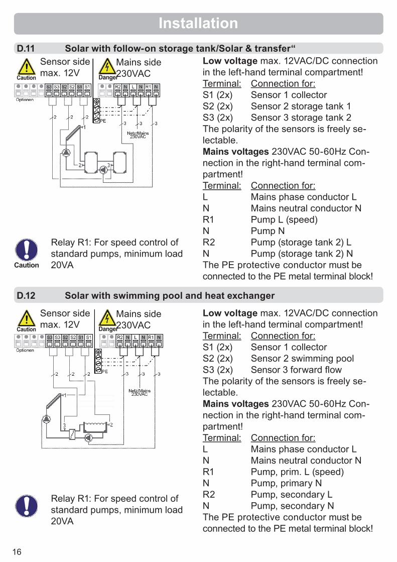
Low voltage max. 12VAC/DC connection in the left-hand terminal compartment!Terminal: Connection for:S1 (2x) Sensor 1 collectorS2 (2x) Sensor 2 storage tank 1S3 (2x) Sensor 3 storage tank 2The polarity of the sensors is freely se-lectable.Mains voltages 230VAC 50-60Hz Con-nection in the right-hand terminal com-partment!Terminal: Connection for:L Mains phase conductor LN Mains neutral conductor NR1 Pump L (speed)N Pump NR2 Pump (storage tank 2) LN Pump (storage tank 2) NThe PE protective conductor must be connected to the PE metal terminal block!
D.11 Solar with follow-on storage tank/Solar & transfer“Sensor sidemax. 12VCaution
Mains side230VAC22222Danger
Caution
Relay R1: For speed control of standard pumps, minimum load 20VA
Low voltage max. 12VAC/DC connection in the left-hand terminal compartment!Terminal: Connection for:S1 (2x) Sensor 1 collectorS2 (2x) Sensor 2 swimming poolS3 (2x) Sensor 3 forward fl owThe polarity of the sensors is freely se-lectable.Mains voltages 230VAC 50-60Hz Con-nection in the right-hand terminal com-partment!Terminal: Connection for:L Mains phase conductor LN Mains neutral conductor NR1 Pump, prim. L (speed)N Pump, primary NR2 Pump, secondary LN Pump, secondary NThe PE protective conductor must be connected to the PE metal terminal block!
Sensor sidemax. 12VCaution
Mains side230VAC22222Danger
D.12 Solar with swimming pool and heat exchanger
Relay R1: For speed control of standard pumps, minimum load 20VA

17
Installation
Low voltage max. 12VAC/DC connection in the left-hand terminal compartment!Terminal: Connection for:S1 (2x) Sensor 1 collectorS2 (2x) Sensor 2 storage tankS3 (2x) Sensor 3 swimming poolThe polarity of the sensors is freely se-lectable.Mains voltages 230VAC 50-60Hz Con-nection in the right-hand terminal com-partment!Terminal: Connection for:L Mains phase conductor LN Mains neutral conductor NR1 Pump L (speed)N Pump NR2 Pump (sec.)+valve LN Pump (sec.)+valve NThe PE protective conductor must be connected to the PE metal terminal block!
Low voltage max. 12VAC/DC connection in the left-hand terminal compartment!Terminal: Connection for:S1 (2x) Sensor 1 collectorS2 (2x) Sensor 2 storage tankS3 (2x) Sensor 3 (optional)The polarity of the sensors is freely se-lectable.Mains voltages 230VAC 50-60Hz Con-nection in the right-hand terminal com-partment!Terminal: Connection for:L Mains phase conductor LN Mains neutral conductor NR1 Pump L (speed)N Pump NR2 Air cooler LN Air cooler NThe PE protective conductor must be connected to the PE metal terminal block!
D.13 Solar storage tank/poolSensor sidemax. 12V
Sensor sidemax. 12V
Caution
Caution
Mains side230VAC22222Danger
Mains side230VAC22222Danger
Caution
Caution
Relay R1: For speed control of standard pumps, minimum load 20VA
Relay R1: For speed control of standard pumps, minimum load 20VA
Actuating direction of valve:R2 on/valve on = charge to sensor 3 (swimming pool)
D.14 Solar + cooling 1
Description of cooling function see 6.4.1
18
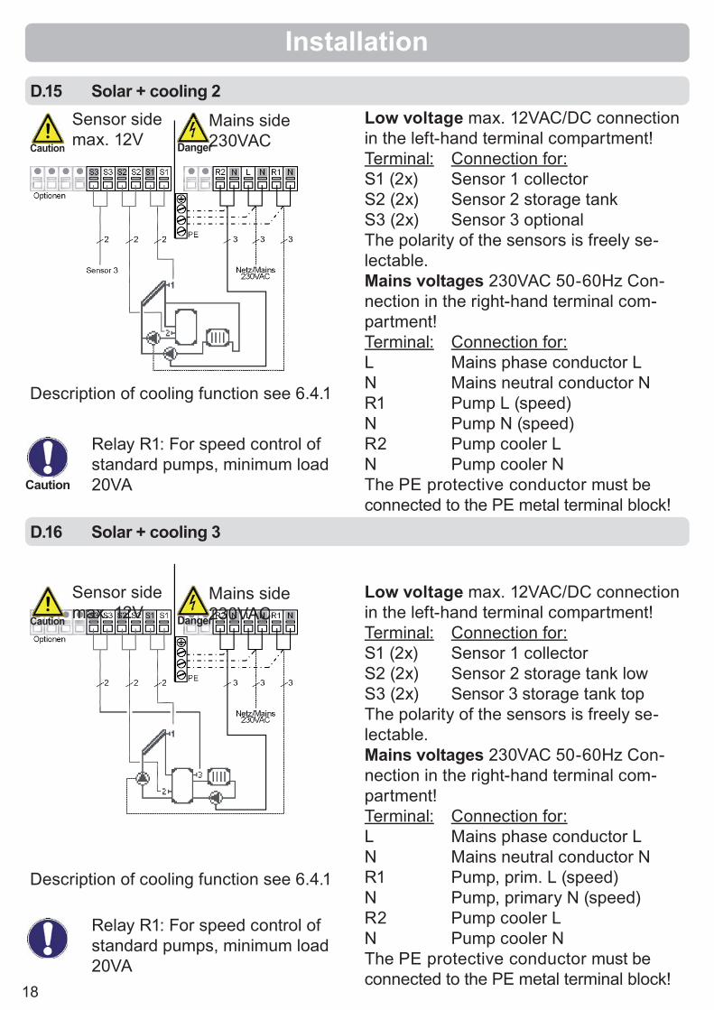
D.15 Solar + cooling 2
D.16 Solar + cooling 3
Installation
Low voltage max. 12VAC/DC connection in the left-hand terminal compartment!Terminal: Connection for:S1 (2x) Sensor 1 collectorS2 (2x) Sensor 2 storage tank lowS3 (2x) Sensor 3 storage tank topThe polarity of the sensors is freely se-lectable.Mains voltages 230VAC 50-60Hz Con-nection in the right-hand terminal com-partment!Terminal: Connection for:L Mains phase conductor LN Mains neutral conductor NR1 Pump, prim. L (speed)N Pump, primary N (speed)R2 Pump cooler LN Pump cooler NThe PE protective conductor must be connected to the PE metal terminal block!
Low voltage max. 12VAC/DC connection in the left-hand terminal compartment!Terminal: Connection for:S1 (2x) Sensor 1 collectorS2 (2x) Sensor 2 storage tankS3 (2x) Sensor 3 optionalThe polarity of the sensors is freely se-lectable.Mains voltages 230VAC 50-60Hz Con-nection in the right-hand terminal com-partment!Terminal: Connection for:L Mains phase conductor LN Mains neutral conductor NR1 Pump L (speed)N Pump N (speed)R2 Pump cooler LN Pump cooler NThe PE protective conductor must be connected to the PE metal terminal block!
Sensor sidemax. 12V
Sensor sidemax. 12V
Caution
Caution
Mains side230VAC2222Danger
Mains side230VAC2222222Danger
Caution
Relay R1: For speed control of standard pumps, minimum load 20VA
Relay R1: For speed control of standard pumps, minimum load 20VA
Description of cooling function see 6.4.1
Description of cooling function see 6.4.1

19
InstallationD.17 Solar + solid fuel boiler
D.18 Solar + valve + thermostat
Low voltage max. 12VAC/DC connection in the left-hand terminal compartment!Terminal: Connection for:S1 (2x) Sensor 1 collectorS2 (2x) Sensor 2 storage tankS3 (2x) Sensor 3 solid fuel boilerThe polarity of the sensors is freely se-lectable.Mains voltages 230VAC 50-60Hz Con-nection in the right-hand terminal com-partment!Terminal: Connection for:L Mains phase conductor LN Mains neutral conductor NR1 Pump L (speed)N Pump N (speed)R2 Pump solid fuel LN Pump solid fuel NThe PE protective conductor must be connected to the PE metal terminal block!
Low voltage max. 12VAC/DC connection in the left-hand terminal compartment!Terminal: Connection for:S1 (2x) Sensor 1 collectorS2 (2x) Sensor 2 storage tank lowS3 (2x) Sensor 3 storage tank topThe polarity of the sensors is freely se-lectable.Mains voltages 230VAC 50-60Hz Con-nection in the right-hand terminal com-partment!Terminal: Connection for:L Mains phase conductor LN Mains neutral conductor NR1 Pump L (speed)N Pump NR2 Valve LN Valve NThe PE protective conductor must be connected to the PE metal terminal block!
Sensor sidemax. 12V
Sensor sidemax. 12V
Caution
Caution
Mains side230VAC22222Danger
Mains side230VAC22222Danger
Caution
Caution
Relay R1: For speed control of standard pumps, minimum load 20VA
Relay R1: For speed control of standard pumps, minimum load 20VA

20
Brief description of switching function:The ΔT function sensor 1 > sensor 2switches the pump to relay R1.The thermostat function via sensor 3switches the pump to relay R2.
D.19 Universal ΔT controller
Installation
Low voltage max. 12VAC/DC connection in the left-hand terminal compartment!Terminal: Connection for:S1 (2x) Sensor 1 (control)S2 (2x) Sensor 2 (reference)S3 (2x) Sensor 3 (thermostat)The polarity of the sensors is freely se-lectable.Mains voltages 230VAC 50-60Hz Con-nection in the right-hand terminal com-partment!Terminal: Connection for:L Mains phase conductor LN Mains neutral conductor NR1 Pump L (speed)N Pump NR2 e.g. pump LN e.g. pump NThe PE protective conductor must be connected to the PE metal terminal block!
Sensor sidemax. 12V
Sensor sidemax. 12V
Caution
Caution
Mains side230VAC2222Danger
Mains side230VAC22222Danger
Caution
Caution
Relay R1: For speed control of standard pumps, minimum load 20VA
Relay R1: For speed control of standard pumps, minimum load 20VA
Brief description of switching function:The ΔT function sensor 1 > sensor 2switches the pump to relay R1.The ΔT function 2 > sensor 3switches the pump to relay R2.
Low voltage max. 12VAC/DC connection in the left-hand terminal compartment!Terminal: Connection for:S1 (2x) Sensor 1 (control)S2 (2x) Sensor 2 (ref.+contr.)S3 (2x) Sensor 3 (reference)The polarity of the sensors is freely se-lectable.Mains voltages 230VAC 50-60Hz Con-nection in the right-hand terminal com-partment!Terminal: Connection for:L Mains phase conductor LN Mains neutral conductor NR1 Pump L (speed)N Pump NR2 e.g. pump LN e.g. pump NThe PE protective conductor must be connected to the PE metal terminal block!
D.20 Universal 2x ∆T-controller

21
Examples of display symbols:
Pump (rotates in operation)
Valve (direction of fl ow black)
Collector
Storage tank
Swimming pool
Temperature sensor
Heat exchanger
Warning/error message
New information available
(1)
(2)
(3)
(4)
The display (1), with its extensive text and graphics mode, is almost self-explanatory, allowing easy operation of the controller.
The LED (2) lights up green when a relay is switched on.The LED (2) lights up red whenoperating mode “Off” is set.The LED (2) fl ashes slowly red in the operating mode “Manual”.
The LED (2) fl ashes quicklyred when an error is present.
Entries are made using four keys (3+4), which are assigned to different functions depending on the situation. The “esc” key (3) is used to cancel an entry or to exit a menu. If applicable there will be a request for confi rmation as to whether the changes which have been made should be saved.The function of each of the other three keys (4) is shown in the display line di-rectly above the keys; the right-hand key is generally has a confi rmation and selec-tion function.
Examples of key functions:
+/- = enlarge/shrink values▼/▲ = scroll menu down/upyes/no = approve/rejectInfo = additional informationBack = to previous screenok = confi rm selectionConfi rm = confi rm setting
Operation
E.1 Display and input

22
E.2 Commissioning help
E.3 Free commissioningIf you decide not to use the commissioning help, you should make the necessary set-tings in the following sequence:- Menu 10. Language (see 14.) - Menu 7.2 Time and date (see 12.2)- Menu 7.1 Program selection (see 12.1)- Menu 5. Settings, all values (see 10.)- Menu 6. Protective functions if adaptations are necessary (see 11.)- Menu 7. Special functions if additional changes are necessary (see 12.)
Finally, menu 4.2 under operating mode “Manual“ should be used to test the switch outputs with the consumers connected, and to check the sensor values for plausibility. Then switch on automatic mode.
brief descriptions of each parameter in the display.Pressing the “esc” key takes you back to the previous value so you can look at the selected setting again or adjust it if desired. Pressing the “esc“ more than once takes you back step by step to the selection mode, thus cancelling the commissioning help. Finally, menu 4.2 under operating mode “Manual” should be used to test the switch outputs with the consumers connected, and to check the sensor values for plausibility. Then switch on automatic mode.
The fi rst time the controller is turned on and after the language and time are set, a query appears as to whether you want to parametrise the controller using the commissioning help or not. The commis-sioning help can also be terminated or called up again at any time in the special functions menu. The commissioning help guides you through the necessary basic settings in the correct order, and provides
Parametrisation
Caution
Observe the explanations for the the individual parameters on the fol-lowing pages, and check whether further settings are necessary for your application.
Caution
Observe the explanations for the the individual parameters on the fol-lowing pages, and check whether further settings are necessary for your application.

23
E.4 Menu sequence and menu structureThe graphics or overview mode appears when no key has been press for 2 min-utes, or when the main menu is exited by pressing “esc“.
Pressing a key in graphics or overview mode takes you directly to the main menu. The following menu items are then avail-able for selection there:
Current temperature values with explana-tions
Function control of the system with oper-ating hours, etc
Select graphics mode or overview mode
Automatic mode, manual mode or switch unit off
Set parameters needed for normal opera-tion
Solar and frost protection, recooling, anti-seizing protection
Program selection, sensor cali-bration, clock, additional sensor, etc.
Against unintentional setting chan-ges at critical points
For diagnosis in the event of an error
Language selection
Operation
1. Measurements
2. Statistics
3. Display Mode
4. Operating Mode
5. Settings
6. Protections
7. Special functions
8. Menu lock
9. Service data
10. Language

24
Caution
The menu “1. Measurement values” serves to display the currently measured temperatures.
The menu is closed by pressing “esc” or selecting “Exit measurement values”.
Selecting “Info” leads to a brief help text explaining the measurement values.
Selecting “Overview” or “esc” exits the Info mode.
If “Error” appears on the display instead of the measurement value, then there may be a defective or incorrect temperature sensor.If the cables are too long or the sensors are not placed optimally, the result may be small deviations in the measurement values. In this case the display values can be compensated for by making entries on the controller. Follow the instructions under 7.3. What measurement values are displayed depends on the selected pro-gram, the connected sensors and the specifi c device design.
Measurement values
1. Measurement values
25
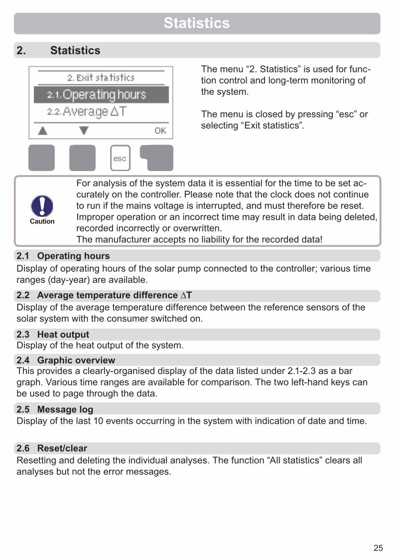
2.1 Operating hours Display of operating hours of the solar pump connected to the controller; various time ranges (day-year) are available.
2.3 Heat output
Display of the average temperature difference between the reference sensors of the solar system with the consumer switched on.
2.2 Average temperature difference ∆T
Display of the heat output of the system.2.4 Graphic overviewThis provides a clearly-organised display of the data listed under 2.1-2.3 as a bar graph. Various time ranges are available for comparison. The two left-hand keys can be used to page through the data.
2.5 Message log
Resetting and deleting the individual analyses. The function “All statistics” clears all analyses but not the error messages.
2.6 Reset/clear
Display of the last 10 events occurring in the system with indication of date and time.
2. Statistics
Caution
The menu “2. Statistics” is used for func-tion control and long-term monitoring of the system.
The menu is closed by pressing “esc” or selecting “Exit statistics”.
For analysis of the system data it is essential for the time to be set ac-curately on the controller. Please note that the clock does not continue to run if the mains voltage is interrupted, and must therefore be reset. Improper operation or an incorrect time may result in data being deleted, recorded incorrectly or overwritten. The manufacturer accepts no liability for the recorded data!
Statistics

26
Menu “3. Display mode” is used to defi ne the controller’s display for normal opera-tion. This display appears whenever two min-utes go by without any key being pressed. The main menu appears again when a key is pressed. The menu is closed by pressing “esc” or selecting “Exit display mode”.
3.1 Schematic
In graphics mode, the selected hydraulic systems are depicted with the measured temperatures and operating states of the connected consumers.
3.2 Overview
In overview mode, the measured temperatures and operating states of the connected consumers are depicted in text form.
3.3 Alternating
In alternating mode the schematic mode and then the overview mode are active for 5 seconds at a time.
Display mode
3. Display mode

27
4. Operating modesIn menu “4. Operating modes” the con-troller can either be placed in automatic mode, switched off, or placed in a manual operating mode.
The menu is closed by pressing “esc” or selecting “Exit operating modes”.
4.2 Manual
Automatic mode is the normal operating mode of the controller. Only automatic mode provides proper controller function taking into account the current temperatures and the parameters that have been set! After an interruption of the mains voltage the con-troller automatically returns to the last operating mode selected!
4.1 Automatic
Operating modes
The relay and thus the connected consumer are switched on and off by pressing a key, with no regard to the current temperatures and the parameters which have been set. The measured temperatures are also shown to provide an overview and function control.
4.3 Off
4.4 Fill system
When the operating mode “Off” is activated, all controller functions are switched off. This can lead, for example, to overheating on the solar collector or other system components. The measured temperatures are sstill displayed to provide an overview.
This special operating mode is intended only for the fi lling procedure for a special “Drain Master System” with a fi ll level contact parallel to col-lector sensor S1. The instructions on the display must be followed when fi lling the system. Be sure to terminate the function when fi nished!
Caution
Danger
When operating mode “Manual” is activated, the current temperatures and the selected parameters are no longer considered. There is a dan-ger of scalding or serious damage to the system. The operating mode “Manual” may only be used by specialists for brief function tests or dur-ing commissioning!
Caution

28
Various settings can be made depending on the selection of hydraulic variant 1-20. This is explained in more detail in Table 5.17. This table also indicates the associated reference sensors and switch outputs. The following pages contain generally valid descriptions for the settings.Caution
Enable/start temperature at sensor 2If this value is exceeded at sensor 2 and the other conditions are also met, then the controller switches the associated pump and/or valve on. If the temperature at sen-sor 2 drops below this value by 5°C, then the pump and/or the valve are switched off again.Setting range: from 0°C to 99°C/default setting: 40°C
Enable/start temperature at sensor 3If this value is exceeded at sensor 3 and the other conditions are also met, then the controller switches the associated pump and/or valve on. If the temperature at sen-sor 3 drops below this value by 5°C, then the pump and/or the valve are switched off again.Setting range: from 0°C to 99°C/default setting: 20°C
5. SettingsThe necessary basic settings required for the control function are made in menu “5. Settings”.
5.1 Tmin S1
5.2 Tmin S2
5.3 Tmin S3
Enable/start temperature at sensor 1If this value is exceeded at sensor 1 and the other conditions are also met, then the controller switches the associated pump and/or valve on. If the temperature at sen-sor 1 drops below this value by 5°C, then the pump and/or the valve are switched off again.Setting range: from 0°C to 99°C/default setting: 20°C
Caution
This does not under any circumstances replace the safety facilities to be provided by the customer!
The menu is closed by pressing “esc” or select-ing “Exit settings”.
Settings

29
Settings5.4 Tmax S2
5.5 Tmax S3
5.6 ∆T R1
Switch-off temperature at sensor 2If this value is exceeded at sensor 2 and the other conditions are also met, then the controller switches the associated pump and/or valve off. If sensor 2 falls below this value again and the other conditions are also met, then the controller switches the pump and/or valve on again.Setting range: from 0°C to 99°C/default setting: 60°C
Switch-off temperature at sensor 3If this value is exceeded at sensor 3 and the other conditions are also met, then the controller switches the associated pump and/or valve off. If sensor 3 falls below this value again and the other conditions are also met, then the controller switches the pump and/or valve on again.Setting range: from 0°C to 99°C/default setting: 60°C (in hydraulic variants without S3 default: Off)
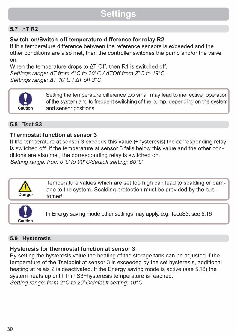
Switch-on/switch-off temperature difference for relay R1If this temperature difference between the reference sensors is exceeded and the other conditions are also met, then the controller switches the relay R1 on.When the temperature drops to ΔT Off, then R1 is switched off.Settings range: ΔT from 4°C to 20°C / ΔTOff from 2°C to 19°CSettings range: ΔT 10°C / ΔT off 3°C.
Danger
Danger
Temperature values which are set too high can lead to scalding or dam-age to the system. Scalding protection must be provided by the cus-tomer!
Temperature values which are set too high can lead to scalding or dam-age to the system. Scalding protection must be provided by the cus-tomer!
If the set temperature difference is too small, this may result in ineffec-tive operation, depending on the system and sensor positions.Special switching conditions apply for speed control (see 7.9)! Caution
30
Settings5.7 ∆T R2
5.8 Tset S3
5.9 Hysteresis
Switch-on/Switch-off temperature difference for relay R2If this temperature difference between the reference sensors is exceeded and the other conditions are also met, then the controller switches the pump and/or the valve on. When the temperature drops to ΔT Off, then R1 is switched off.Settings range: ΔT from 4°C to 20°C / ΔTOff from 2°C to 19°CSettings range: ΔT 10°C / ΔT off 3°C.
Thermostat function at sensor 3If the temperature at sensor 3 exceeds this value (+hysteresis) the corresponding relay is switched off. If the temperature at sensor 3 falls below this value and the other con-ditions are also met, the corresponding relay is switched on.Setting range: from 0°C to 99°C/default setting: 60°C
Hysteresis for thermostat function at sensor 3By setting the hysteresis value the heating of the storage tank can be adjusted.If the temperature of the Tsetpoint at sensor 3 is exceeded by the set hysteresis, additional heating at relais 2 is deactivated. If the Energy saving mode is active (see 5.16) the system heats up until TminS3+hysteresis temperature is reached.Setting range: from 2°C to 20°C/default setting: 10°C
Setting the temperature difference too small may lead to ineffective operation of the system and to frequent switching of the pump, depending on the system and sensor positions.
In Energy saving mode other settings may apply, e.g. TecoS3, see 5.16
Temperature values which are set too high can lead to scalding or dam-age to the system. Scalding protection must be provided by the cus-tomer!
Caution
Caution
Danger

31
Settings5.10 Priority sensorCharging priority in systems with two storage tanksA setting must be made as to which storage tank (storage tank sensor) has priority for charging. Charging of the lower-priority storage tank is interrupted at regular intervals to check whether the temperature increase at the collector can enable charging of the higher-priority storage tank.Setting range: S2 or S3/default setting: S2
5.11 T priorityTemperature threshold for absolute priorityIn systems with two storage tanks charging of the lower-priority storage tank will never take place until this set temperature setpoint at the storage tank sensor of the higher-priority storage tank is exceeded.Setting range: from 0°C to 90°C/default setting: 40°C
5.13 IncreaseExtension of the charging pause due to temperature increase in the collectorFor precise setting of the charging priorities for systems with multiple storage tanks, the necessary temperature increase of the collector at which the interruption of the charging into the lower-priority storage tank is extended by one minute is set here. The interruption is extended because the temperature increase of the collector is expected to enable charging in the higher-priority storage tank soon.As soon as ∆T conditions are met, the priority storage tank is charged. If the rise in temperature falls below the set value, then the charging of the lower-priority storage tank is enabled again.Setting range: from 1°C to 10°C/default setting: 3°C
5.12 Loading timeInterruption of charging into the lower priority storage tankThe charging of the lower-priority storage tank is interrupted after the settable time in order to check whether the collector has reached a temperature level that allows charging in the higher-priority storage tank. If so, the priority storage tank is charged.If not, the increase is measured (see 5.13), to check if charging of the priority storage tank will be possible shortly.Setting range: from 5 to 90 minutes/default setting: 10 minutes
5.14 Thermostat periodsThermostat activity timesSet the desired periods of time when the thermostat should be active. 2periods can be set per day, settings can also be copied to other days.Outside the set times the thermostat is switched off.Setting range: from 00:00 to 23:59 /default setting: 06:00 to 22:00
32
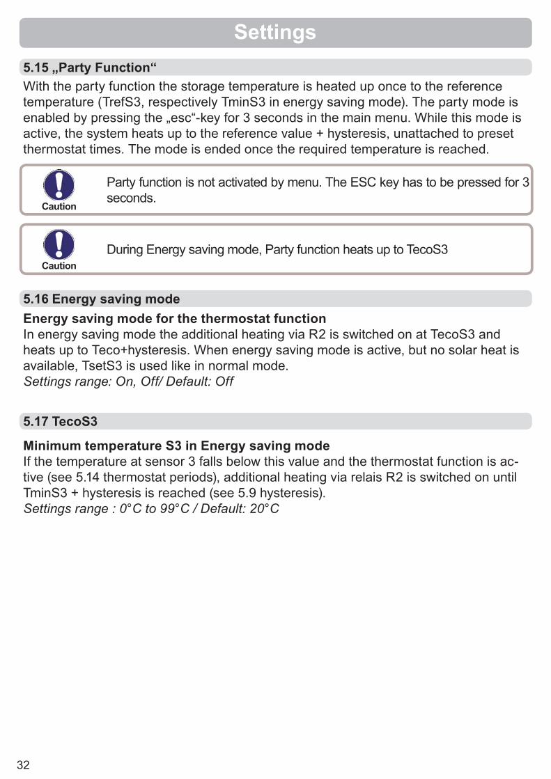
Settings5.15 „Party Function“With the party function the storage temperature is heated up once to the reference temperature (TrefS3, respectively TminS3 in energy saving mode). The party mode is enabled by pressing the „esc“-key for 3 seconds in the main menu. While this mode is active, the system heats up to the reference value + hysteresis, unattached to preset thermostat times. The mode is ended once the required temperature is reached.
Party function is not activated by menu. The ESC key has to be pressed for 3 seconds.
During Energy saving mode, Party function heats up to TecoS3
Caution
Caution
5.17 TecoS3
Minimum temperature S3 in Energy saving modeIf the temperature at sensor 3 falls below this value and the thermostat function is ac-tive (see 5.14 thermostat periods), additional heating via relais R2 is switched on until TminS3 + hysteresis is reached (see 5.9 hysteresis). Settings range : 0°C to 99°C / Default: 20°C
5.16 Energy saving modeEnergy saving mode for the thermostat function In energy saving mode the additional heating via R2 is switched on at TecoS3 and heats up to Teco+hysteresis. When energy saving mode is active, but no solar heat is available, TsetS3 is used like in normal mode.Settings range: On, Off/ Default: Off

33
5.18
Tab
le: P
rogr
ams
(hyd
raul
ic v
aria
nts)
with
ass
ocia
ted
setti
ngs
The
tabl
e lis
ts th
e se
tting
s co
rresp
ondi
ng to
the
spec
ifi c p
rogr
ams
(hyd
raul
ic va
riant
s). T
he re
fere
nce
sens
ors
1-3
corre
spon
ding
to th
e fu
nctio
ns
are
labe
lled
S1-S
3. T
he s
witc
h ou
tput
s (re
lays
) cor
resp
ondi
ng to
the
func
tions
for p
umps
and
val
ves
are
labe
lled
with
R1
or R
2. T
he s
ettin
gs,
setti
ng ra
nges
and
def
ault
setti
ngs
are
expl
aine
d un
der 5
.
Settings
12
34
56
78
910
1112
1314
1516
1718
1920
Tmin
S1
S1
=>R
1+R
2S
1=>
R1
S1
=>R
1S
1=>
R1
S1
=>R
1S
1=>
R2
S1
=>R
1S
1=>
R1
S1
=>R
1S
1=>
R1+
R2
S1
=>R
1S
1=>
R1
S1
=>R
1S
1=>
R1
S1
=>R
1S
1=>
R1
S1
=>R
1S
1=>
R1
S1
=>R
1S
1=>
R1
Tmin
S2
S2
=>R
2S
2=>
R2
S2
=>R
2
Tmin
S3
S3
=>R
1+R
2S
3=>
R2
S3
=>R
2
Tmax
S2
S2
=>R
1+R
2S
2=>
R1
S2
=>R
1+R
2S
2=>
R1
S2
=>R
1S
2=>
R1+
R2
S2
=>R
1+R
2S
2=>
R1+
R2
S2
=>R
1S
2=>
R1
S2
=>R
1S
2=>
R1+
R2
S2
=>R
1S
2=>
R1
S2
=>R
1S
2=>
R1
S2
=>R
1+R
2S
2=>
R1
S2
=>R
1S
2=>
R1
Tmax
S3
S3
=>R
2S
3=>
R1+
R2
S3
=>R
1+R
2S
3=>
R2
S3
=>R
2S
3=>
R1+
R2
S3
=>R
2
ΔT R
1
S1/
S2
=>R
1+R
2S
1/S
2=>
R1
S1/
S2
=>R
1S
3/S
2=>
R2
S1/
S2
=>R
1
S1/
S2
=>R
1S
1/S
3=>
R1+
R2
S1/
S2
=>R
2S
3/S
2=>
R1
S1/
S2
=>R
1S
3/S
2=>
R1+
R2
S1/
S2
=>R
1
S1/
S2
=>R
1S
1/S
3=>
R1+
R2
S1/
S2
=>R
1S
1/S
2=>
R1
S1/
S2
=>R
1S
3/S
2=>
R2
S1/
S2
=>R
1S
1/S
3=>
R1+
R2
S1/
S2
=>R
1S
1/S
2=>
R1
S1/
S2
=>R
1S
1/S
2=>
R1
S1/
S2
=>R
1S
1/S
2=>
R1
S1/
S2
=>R
1
ΔT R
2S
2/S
3=>
R2
S3/
S2
=>R
2S
1/S
3=>
R2
S2/
S3
=>R
2S
3/S
2=>
R2
S2/
S3
=>R
2
Tset
S3
S3
=>R
2S
3=>
R2
S3
=>R
2S
3=>
R2
Hys
tere
sis
S3
=>R
2S
3=>
R2
S3
=>R
2S
3=>
R2
Prio
rity
S2
o. S
3=>
R1/
R2
S2
o. S
3=>
R1/
R2
S2
o. S
3=>
R1/
R2
S2
o. S
3=>
R1/
R2
T-pr
iorit
yS
2 o.
S3
=>R
1/R
2S
2 o.
S3
=>R
1/R
2S
2 o.
S3
=>R
1/R
2S
2 o.
S3
=>R
1/R
2

34
Menu “6. Protective functions” can be used to activate and set various protective functions.
The menu is closed by pressing “esc” or select-ing “Exit settings”.
Caution
This function causes energy to be lost via the collector! It is normally not activated for solar systems with antifreeze. Observe the operating instructions for the other system components!
Protective functions
6. Protective functions
If the seizing protection is activated, then the controller switches the relay in question and the connected consumer on every day at 12:00 and on Sundays at 12:00 for 5 seconds in order to prevent the pump and/or the valve from sticking after an extended stationary period. Setting range R1: daily, weekly, off/default setting: OffSetting range R2: daily, weekly, off/default setting: Off
A two-stage frost protection function can be activated. In stage 1 the controller switches the pump on for 1 minute every hour if the collector temperature drops below the set value “Frost stage 1”. If the collector temperature drops further to the set value “Frost stage 2” the controller switches the pump on continuously.If the collector temperature then exceeds the value “Frost stage 2” by 2°C, then the pump switches off again.Frost protection setting range: on, off/default setting: offFrost stage 1 setting range: from -25°C to 10°C or off/default setting: 7°CFrost stage 2 setting range: from -25°C to 8°C/default setting: 5°C
6.1 Seizing protection
6.2 Frost protection
Caution
This does not under any circumstances replace the safety facilities to be provided by the customer!

35
Protective functions
Cooling functions ->
6.4 Collector protection
6.3 System protection
Collector protection prevents overheating of the collector. The pump is switched on to transfer heat from the collector to the storage tank.If “CP Ton” is exceeded at the collector sensor, the pump is switched on until the tem-perature reaches “CP Toff” or the temperature “CP Tmax storage” is exceeded in the storage or pool.Collektor protection settings range: on / off / Voreinstellung: offCP Ton settings range: 60°C to 150°C / Default: 110°CCP Toff settings range: 50°C to Ton minus 5°C / Default: 100°CCP Tmax storagesettings range: 0°C to 140°C / Default: 90°C
priority protection System protection prevents overheating of system components by automatic shutdown of the solar pump. If “SProt Ton” is exceeded at the collector, the pump is switched off. The pump is activated again when the temperature drops below “SProt TOff”.Automatic shutdown - settings range: On / Off / Default: onSProt Ton - settings range: 60 °C to 150 °C / Default: 120 °CSProt Toff - settings range: 50 °C to Ton minus 5 °C / Default: 115 °C
Protective functions
Caution
When system protection is on, the temperature in the idle collector will be very high, thus the pressure in the system will rise and can damage your system.Pay close attention to the instructions of the system manufacturer.
Danger
When collector protection is active, the storage or pool is heated well beyond Tmax S2 (see 5.2) which can result in scalding and system dam-age.
36
6.4.1 Cooling functions
6.6 Recooling
The hydraulic variants are set in menu „7.1 Program selection“
Hydraulic Variant D.14 Solar + cooling 1: If „CProt Ton“ is exceeded at S1, the cooler at R2 is switched on till the temperature drops to „CProt Toff“. If the storage tank exceeds „CProt Tmax storage“, the system is switched off.
Hydraulic Variant D.15 Solar + cooling 2:If „CProt Ton“ is exceeded at S1, the cooler at R2 is switched on. If the storage tank exceeds „CProt Tmax storage“, R1 is switched off with R2 still running to keep on cool-ing. If the temperature at S1 drops to „CProt Toff“, cooling is switched off.
Hydraulic Variant D.16 Solar + cooling 3:If „CProt Ton“ is exceeded at S1, the pump at R1 is switched on to cool the collector by heating up the storage tank.If the storage tank S2 reaches „CProt Tmax storage“, R1 is switched off.Once the storage tank at S3 exceeds TsetS3, cooling at R2 is switched on till „TsetS3“-hysteresis is reached.
In hydraulic systems with solar when the recooling function is activated excess energy from the storage tank is fed back into the collector. This only takes place if the temperature in the storage tank is higher than the value “Recool Tsetpoint” and the collector is at least 20°C cooler than the storage tank and before the storage tank temperature has dropped below the value “Recool Tsetpoint”. In systems with two storage tanks the setting applies to both storage tanks.Recooling setting range: on, off/default setting: offRecooling Tsetpoint setting range: from 0°C to 99°C/default setting: 70°C
6.5 Col.- Alarm
If this temperature is exceeded at the collector sensor when the solar pump is on a warning or error message is triggered. A warning message is shown in the display.Collector alarm settings range: on / off / Default: offCol. alarm - setting range: 60 °C to 300 °C / Default: 150 °C
Protective functions
Caution
This function causes energy to be lost via the collector! Recooling should only be exceptionally.

37
Protective functions
With the “AL function” activated the TDC3 makes it possible to heat the storage tank up once at certain intervals (the “AL frequency”) to a higher temperature (“AL Tsetpoint S2”), assuming that the energy source allows this.AL function setting range: On or Off/default setting: OffAL Tsetpoint S2 setting range: from 60°C to 99°C/default setting: 70°CAL frequency setting range: from 1 to 28 days/default setting: 7 daysAL Heat (not settable): Shows the last time the AL function was active
6.7 Anti-Legionella
Caution
The anti-Legionella function is switched off at delivery. This function is only relevant for storage tanks where sensor 2 is installed. Whenever heating-up has been carried out with the anti-Legionella function switched on, an information message with the date appears on the display.
During the anti-Legionella function the storage tank is heated up over the set value “Tmax S2”, which can lead to scalding and damage to the system.Danger
This anti-Legionella function does not provide complete protection against Legionella, because the controller is dependent on suffi cient energy being fed in, and it is not possible to monitor the temperatures in the entire range of the storage tanks and the connected piping system. To provide complete protection against Legionella bacteria, it must be ensured that the temperature is raised to the necessary temperature, and at the same time there must be water circulation in the storage tank and piping system by means of other additional energy sources and control units.
Caution

38
Special functions
Menu “7. Special functions” is used to set basic items and expanded functions.
The menu is closed by pressing “esc” or select-ing “Exit special functions”.
7. Special functions
Caution
Other than the time all settings may only be made by a specialist.
The suitable hydraulic variant for the specifi c application is selected and set here (see B.5 Hydraulic variants). The associated diagram can be displayed by pressing “info”. Setting range: 1-15/default setting: 1
7.1 Program selections
Caution
Normally the program selection is made only once during initial com-missioning by the specialist. Incorrect program selection can lead to unpredictable errors.
This menu is used to set the current time and date.7.2 Time & date
Caution
For analysis of the system data it is essential for the time to be set accurately on the controller. Please note that the clock does not continue to run if the mains voltage is interrupted, and must therefore be reset.
Deviations in the temperature values displayed, for example due to cables which are to long or sensors which are not positioned optimally, can be compensated for manually here. The settings can be made for each individual sensor in steps of 0.5°C.Offset S1...S3 per setting range: -100 to +100 (translates to -50°C...+50°C)Default setting: 0
7.3 Sensor calibration
Caution
Settings are only necessary in special cases at the time of initial com-missioning by the specialist. Incorrect measurement values can lead to unpredictable errors.

39
Special functions
Starting the commissioning help guides you in the correct order through the basic set-tings necessary for commissioning, and provides brief descriptions of each parameter in the display.Pressing the “esc” key takes you back to the previous value so you can look at the se-lected setting again or adjust it if desired. Pressing the “esc” more than once takes you back to the selection mode, thus cancelling the commissioning help. (see also E.2).
7.4 Commissioning
Caution
May only be started by a specialist during commissioning! Observe the explanations for the the individual parameters in these instructions, and check whether further settings are necessary for your application.
All of the settings that have been made can be reset, thus returning the controller to its delivery state.
7.5 Factory settings
This menu can only be selected and used if additional options or expansions have been built into the controller.The associated supplementary installation, mounting and operation instructions are then included with the specifi c expansion.
7.6 Expansions
Caution
The entire parametrisation, analyses, etc. of the controller will be lost irrevocably. The controller must then be commissioned once again.
A simple heat metering function for basic system control can be activated in this menu. Additional settings regarding the glycol, the percentage of gylcol and the fl ow rate of the system are required.
7.7 Heat quantity
CautionResulting data is only approximate value for function control!

40
Activate or deactivate the heat metering functionSettings range: On/off /default setting: Off
Adjust the type of glycol that has been used in the system.Settings range: Ethylene/Propylene /default setting: Ethylene
Adjust the percentage of glycol that has been used in the system.Settings range: 0-60% /default setting: 40%
Adjust the fl ow rate according to the system.Settings range: 10-5000 l/h /default setting: 500 l/h
Since the calculation of the heat metering is based on the temperature of the collec-tor and storage where measuring takes place, a possible deviation from the fl ow and return temperature can be compensated with this value.Example: Displayed collector temp. 40° C, measured fl ow temp. 39° C, displayed stor-age temp. 30° C, measured return temp. 31° C means a setting of -20% (Displayed ΔT 10K, actual ΔT 8K => -20% correction value)Settings range: -50% to +50% /default settings: 0%
With some solar systems, especially with vacuum tube collectors, it may occur that the measurement value acquisition at the collector sensor occurs too slowly or too inac-curately because the sensor is often not at the hottest location. When the start help is activated the following sequence is carried out: If the temperature at the collector sensor increases by the value specifi ed under “Increase” within one minute, then the solar pump is switched on for the set “Purg-ing time” so that the medium to be measured can be moved to the collector sensor. If this still does not result in a normal switch-on condition, then the start help function is subject to a 5-minute lockout time. Start help setting range: on, off/default setting: offPurging time setting range: 2 ... 30 sec./default setting: 5 sec.Increase setting range: 1°C....10°C/default setting: 3°C/min.
7.8 Start aid function
7.7.1 Heat metering
7.7.2 AF type
7.7.3 Glycol portion
7.7.4 Flow rate
7.7.5 ∆T Offset
Caution
This function should only be activated by a specialist if problems arise with acquisition of measurement values. In particular follow the instruc-tions from the collector manufacturer.
Special functions

41
If the speed control is activated, the TDC3 makes it possible to vary the speed of standard pumps at relay R1 by means of special internal electronics.
7.9 Speed control
7.9.1 VariantThe following speed variants are available here:Off: There is no speed control. The connected pump is only switched on or off with full speed.Variant V1: After the purging time the controller switches to the set max. speed. If the temperature difference ∆T between the reference sensors (collector and storage tank) is less than the set value, then the speed is decreased by one stage after the control time elapses. If the temperature difference between the reference sensors is greater than the set value, then the speed is increased by one stage after the control time elapses. If the controller has adjusted the speed of the pump down to the smallest stage and the ∆T between the reference sensors is ∆T off, the pump is switched off.Variant V2: After the purging time the controller switches to the set min. speed. If the temperature difference ∆T between the reference sensors (collector and storage tank) is greater than the set value, then the speed is increased by one stage after the control time elapses. If the temperature difference ∆T between the reference sensors is below the set value, then the speed is decreased by one stage after the control time elapses. If the controller has adjusted the speed of the pump down to the smallest stage and the ∆T between the reference sensors is T∆off, the pump is switched off.Variant V3: After the purging time the controller switches to the set min. speed. If the temperature at the reference sensor (collector) is greater than the setpoint to be set subsequently, then the speed is increased by one stage after the control time expires. If the temperature at the reference sensor (collector) is less than the setpoint to be set subsequently, then the speed is decreased by one stage after the control time expires.Setting range: V1,V2,V3, off/default setting: offVariant V4: (2 storages)When the valve is set toward the primary storage, speed control works as in V3.When the valve is set toward the secondary storage, speed control works as in V2.Settings range: V1,V2,V3, Off / Default: Off
This function should only be activated by a specialist. Depending on the pump and pump stage used, the minimum speed should not be set too low, because otherwise the pump or the system may be damaged. The information provided by the relevant manufacturer must also be ob-served! If in doubt, the min. speed and the pump stage should generally be set to high rather than too low.
Caution
Speed control settings continued on page 42
Special functions

42
During this time the pump starts up at its full speed (100%) to ensure reliable starting. Only after this purging time does the pump run with speed control and switches to the max. or min. speed, depending on the variant set.Setting range: from 5 to 600 seconds/default setting: 8 seconds
The control time is used to determine the delay for speed control in order to avoid large temperature oscillations as much as possible. The time span required for a com-plete control process from minimum speed to maximum speed is entered here.Setting range: from 1 to 15 minutes/default setting: 4 minutes
The maximum speed of the pump at relay R1 is specifi ed here. During the setting the pump runs at the specifi ed speed and the fl ow rate can be determined. Setting range: from 70 to 100%/default setting: 100%
The minimum speed of the pump at relay R1 is specifi ed here. During the setting the pump runs at the specifi ed speed and the fl ow rate can be determined. Setting range: from 30 to max. speed -5%/default setting: 50%
This value is the control setpoint for variant 3. If the value at the collector sensor drops below this, the speed is reduced. If it rises above this, the speed is increased.Setting range: from 0 to 90°C/default setting: 60°C
7.9.2 Purging time
7.9.3 Sweep time
7.9.4 Max. speed
7.9.5 Min. speed
7.9.6 Setpoint
Caution
The indicated percentages are guide values that may vary to a greater or lesser extent depending on the system, pump and pump stage.
Caution
The indicated percentages are guide values that may vary to a greater or lesser extent depending on the system, pump and pump stage.
Special functions

43
The menus listed below remain completely accessible despite the menu lock being activated, and can be used to make adjustments if necessary:1. Measurement values2. Analysis3. Display mode7.2. Time&date8. Menu lock9. Service values
To lock the other menus, select “Menu lock on”.To enable the menus again, select “Menu lock off”.Setting range: on, off/default setting: off
Menu lock
Menu “8. Menu lock” can be used to secure the controller against unintentional changing of the set values.
The menu is closed by pressing “esc” or select-ing “Exit menu lock”.
8. Menu lock
10. LanguageMenu “10. Language” can be used to se-lect the language for the menu guidance. This is queried automatically during initial commissioning.The choice of languages may differ, however, depending on the device design. Language selection is not available in every device design!
Language
44
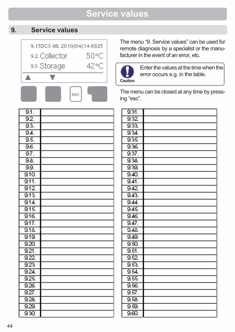
The menu “9. Service values” can be used for remote diagnosis by a specialist or the manu-facturer in the event of an error, etc.
The menu can be closed at any time by press-ing “esc”.
Service values
9. Service values
Caution
Enter the values at the time when the error occurs e.g. in the table.

45
(LED fl ashes + warning symbol)
Z.1. Malfunctions with error messages
Malfunctions
If the controller detects a malfunction, the red light fl ashes and the warning symbol also appears in the display. If the error is no longer present, the warning symbol changes to an info symbol and the red light no longer fl ashes. To obtain more detailed information on the error, press the key under the warning or info symbol.
Possible error messages: Notes for the specialist:Sensor x defective ----------------> Means that either the sensor, the sensor input
at the controller or the connecting cable is/was defective.(Resistance table see B.1)
Collector alarm --------------------> Means that the collector has fallen/fell below the temperature set under menu 6.5
Night circulation -------------------> Means that the solar pump is/was in operation between 23:00 and 04:00. (Exception see 6.6)
Restart ------------------------------> Means that the controller was restarted, for exam-ple due to a power failure. Check the date&time!
Time&date -------------------------> This message appears automatically after a mains failure because the time&date have to be checked, and reset if necessary.
Danger
Do not try to deal with this yourself.Consult a specialist in the event of an error!

46
If the mains voltage is switched on and the controller still does not function or display anything, then the internal device fuse may be defective. In that case, open the device as described under C, remove the old fuse and check it.Exchange the defective fuse for a new one, locate the external source of the er-ror (e.g. pump) and exchange it. Then fi rst recommission the controller and check the function of the switch outputs in manual mode as described under 4.2.
Fuse
Malfunctions
Danger
Danger
Repairs and maintenance may only be performed by a specialist. Before working on the unit, switch off the power supply and secure it against being switched on again! Check for the absence of power!
Only use the supplied spare fuse or a fuse of the same design with the following specifi cations: T2A 250V
Z.2 Replacing the fuse
Z.2.1
Z.3 Maintenance
Caution
In the course of the general annual maintenance of your heating system you should also have the functions of the controller checked by a spe-cialist and have the settings optimised if necessary.
Performing maintenance:- Check the date and time (see 7.2)- Assess/check plausibility of analyses (see 2.4)- Check the error memory (see 2.5)- Verify/check plausibility of the current measurement values (see 1.)- Check the switch outputs/consumers in manual mode (see 4.2)- Poss. optimise the parameter settings
47
Instead of setting the fl ow rate for the system using a fl ow rate limiter, it is better to adjust the fl ow rate using the switch on the pump and by means of the “max. speed” setting on the controller (see 7.9.4). This saves electricity!The service values (see 9.) include not only current measurement val-ues and operating states, but also all of the settings for the controller. Write the service values down just once after commissioning has been successfully completed.In the event of uncertainty as to the control response or malfunctions the service values are a proven and successful method for remote diag-nosis. Write the service values down (see 9.) at the time that the sus-pected malfunction occurs. Send the service value table by fax or e-mail with a brief description of the error to the specialist or manufacturer.
In program 13 “Solar with storage tank and pool” the charging of the pool, e.g. for winter operation, can be switched off using a simple func-tion. To do this, simply press and hold the “esc” key down for several seconds on the diagram/overview screen. A message appears on the display as soon as the pool is switched off or when the pool is switched on again.
In program 1 “Solar with storage tank” the mechanical relay R2 switches together with the speed-controlled output R1. Relay output R2 can be used to operate larger loads up to 460VA, as well as valves or auxiliary relays with low power.
Programs 19 + 20 “Universal ∆T controller” are suitable, for example, for hydraulic variants with solid-fi red boiler, follow-on storage tank charging, storage tank transfer, heating circuit return lift, etc.The Operating hours displayed in the “Analysis” menu are solar oper-ating hours. This therefore only takes into account hours in which the solar pump is active. In the universal programs 19 + 20 the times refer to relay R1.To protect against loss of data, record any analyses and data that are particularly important to you (see 2.) at regular intervals.
Useful notes/tips and tricks

48
Final declaration:Although these instructions have been created with the greatest possi-ble care, the possibility of incorrect or incomplete information cannot be excluded. Subject as a basic principle to errors and technical changes.
Notes:
Hydraulic variant set:
Commissioned on:
Commissioned by:
Manufacturer:SOREL GmbH MikroelektronikJahnstr. 36D - 45549 SprockhövelTel. +49 (0)2339 6024Fax +49 (0)2339 6025www.sorel.de [email protected]
Your specialist dealer:
L:\B
edie
nanl
eitu
ngen
\S\T
DC
\TD
C3
5L E
nglis
ch R
edes
ign\
TDC
3 5L
eng
lish1
0089
6.in
dd