Embed Size (px)
Citation preview
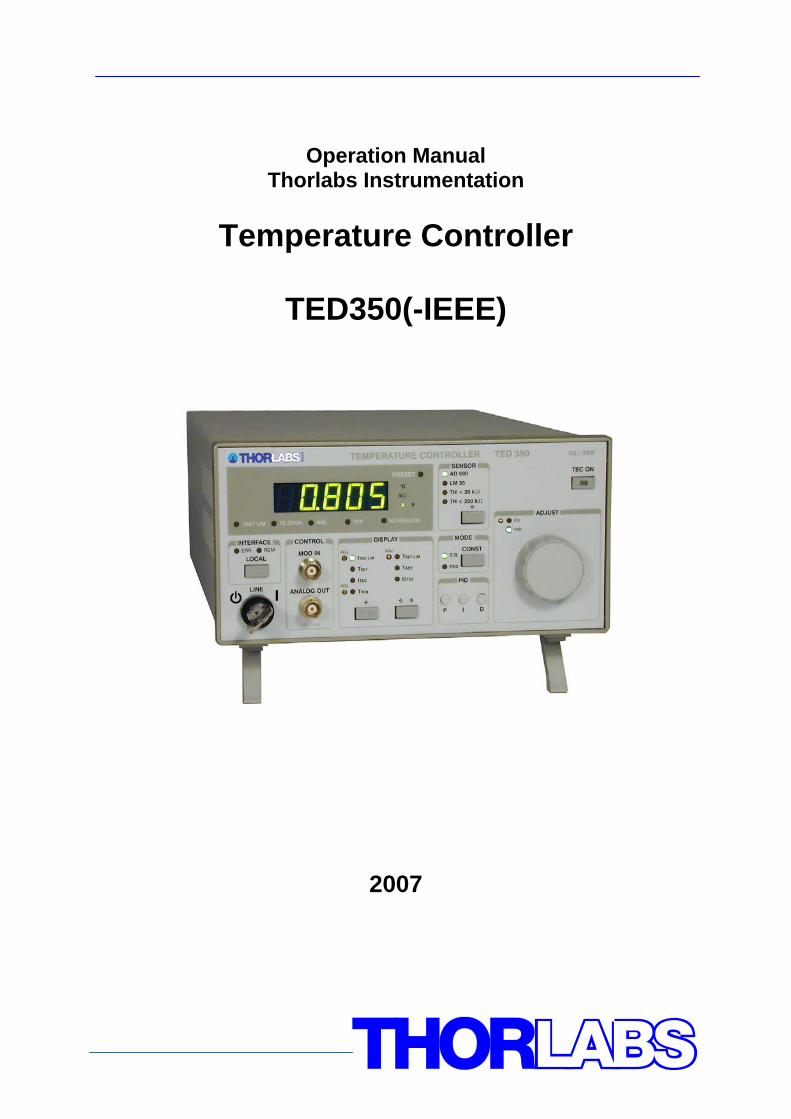
Operation Manual Thorlabs Instrumentation
Temperature Controller
TED350(-IEEE)
2007

Version: 2.14 Date: 07.02.2007 Copyright© 2007, Thorlabs, Germany
Contents Page 1 General description of the TED350 controller 1
1.1 Packing List 1 1.2 Safety 1 1.3 General functions 3
1.3.1 Protections for the TEC element 3 1.3.2 Description of operation 4
1.4 Technical data 5 1.5 Operating elements 8
1.5.1 Front panel 8 1.5.2 Back panel 9
1.6 Pre-settings 10 1.6.1 Setting the limit value of the TEC current 10 1.6.2 Setting the maximum allowed temperature 10 1.6.3 Setting the temperature window 10
1.7 Connecting components 11 1.7.1 Pin assignment of the output jack 11 1.7.2 Connecting a thermistor 12 1.7.3 Connecting a temperature sensor AD590 or AD592 13 1.7.4 Connecting a temperature sensor LM135 or LM335 13 1.7.5 Connecting an LM35 14 1.7.6 Connecting the Pt-100 (option) 15 1.7.7 Connecting a TEC element 15 1.7.8 Connecting the status indicator 17 1.7.9 Fine tuning of the temperature 18
2 Operating the TED350 19 2.1 Manual operation 19
2.1.1 Selecting the sensor 19 2.1.2 Selecting the mode of operation 20 2.1.3 Selecting the displayed value 20 2.1.4 The output ANALOG OUT 21 2.1.5 Switching the output ON and OFF 21 2.1.6 Setting the PID shares 21 2.1.7 WIN OUT 21 2.1.8 Fix / Var selector 22 2.1.9 Wakeup setting DIP switch 22
2.2 Optimization of temperature control loops 24 2.2.1 Setup and function of temperature controllers 24
2.2.2 PID adjustment 26 3 Communication with a control computer (TED350-IEEE) 28
3.1 IEEE488 interface (TED350-IEEE) 29 3.1.1 IEEE 488 Interface subsets 29 3.1.2 Setting up the interface 30 3.1.3 Connecting the PC 32 3.1.4 IEEE488 bus commands 33
3.2 Before Programming 35 3.2.1 Nomenclature 35 3.2.2 Program and response messages 35 3.2.3 Data format 36
3.3 Common commands and queries 37 3.3.1 Identification query 37 3.3.2 Reset 37 3.3.3 Self-test query 37 3.3.4 Set Operation-complete bit 37 3.3.5 Operation-complete query 38 3.3.6 Wait 38 3.3.7 Event-Status-Enable-Register (ESE) 38 3.3.8 Query Standard-Event-Status-Register (ESR) 38 3.3.9 Service-Request-Enable-Register (SRE) 39 3.3.10 Query Status-Byte-Register (STB) 39
3.4 System command group 40 3.4.1 Answer mode 40 3.4.2 Error-LED mode 40 3.4.3 Querying the error queue 41 3.4.4 Oversampling rate 41
3.5 Status command group 42 3.5.1 Query Device-Error-Condition-Register (DEC) 42 3.5.2 Query Device-Error-Event-Register (DEE) 42 3.5.3 Device-Error-Event-Enable-Register (EDE) 42
3.6 TED350 specific commands 43 3.6.1 Temperature sensor (SENS) 43 3.6.2 Operation mode (MODE) 43 3.6.3 Switching the TEC on and off (TEC) 44 3.6.4 Reading the TEC current hardware limit (LIMTP) 44 3.6.5 Reading the TEC temperature / resistance hardware limit (LIMTR)44 3.6.6 Temperature (only AD590 and LM35) (TEMP) 45 3.6.7 Resistance (only thermistor) (RESI) 46
3.6.8 TEC current (ITE) 47 3.6.9 Reading the temperature/resistance window (WIN) 48 3.6.10 Reading the TEC voltage (VTE) 48
3.7 Error messages of the TED350 49 3.7.1 General errors 49 3.7.2 TED350 operation error messages 51
3.8 Status reporting 53 3.8.1 Standard event status register (ESR) 55 3.8.2 Standard event status enable register (ESE) 55 3.8.3 Status byte register (STB) 56 3.8.4 Service request enable register (SRE) 56 3.8.5 Reading the STB by detecting SRQ 57 3.8.6 Reading the STB by *STB? command 57 3.8.7 Reading the STB by serial poll 57 3.8.8 Device error condition register (DEC) 58 3.8.9 Device error event register (DEE) 59 3.8.10 Device error event enable register (EDE) 59
3.9 Hints for setting up control programs 60 4 Maintenance and Repair 63
4.1 General remarks 63 4.2 Cleaning 63 4.3 Selecting the line voltage 64 4.4 Exchanging the line fuse 64 4.5 Troubleshooting 66
5 Service 68 5.1 Exchange of internal fuses 68
6 Appendix 69 6.1 Warranty 69 6.2 Certifications and compliances 70 6.3 Thorlabs “End of Life” policy (WEEE) 71
6.3.1 Waste treatment on your own responsibility 72 6.3.2 Ecological background 72
6.4 List of acronyms 74 6.5 List of figures 75 6.6 List of tables 76 6.7 Addresses 76
We aim to develop and produce the best solution for your application in the field of optical measurement technique. To help us to come up to your expectations and develop our products permanently we need your ideas and suggestions. Therefore, please let us know about possible criticism or ideas. We and our international partners are looking forward to hearing from you.
Thorlabs This part of the instruction manual contains specific information on how to operate the temperature controller TED350. A general description is followed by explanations of how to operate the unit manually. You will also find information about remote control via the optional IEEE 488 computer interface.
Attention This manual contains “WARNINGS” and “ATTENTION” label in this form, to indicate dangers for persons or possible damage of equip-
ment.
Please read these advises carefully!
NOTE This manual also contains “NOTES” and “HINTS” written in this form.
1.1 Packing List
TED350 / page 1
1 General description of the TED350 controller
1.1 Packing List
1 TED350 (-IEEE) 1 power cord, connector according to ordering country 1 operation manual 1 CD-ROM with Drivers (TED350-IEEE only) 1 connection cable CAB420-15
1.2 Safety
Attention All statements regarding safety of operation and technical data in this instruction manual will only apply when the unit is operated
correctly.
Before applying power to your TED350 system make sure that the protective conductor of the 3 conductor mains power cord is cor-
rectly connected to the protective earth contact of the socket outlet! Improper grounding can cause electric shock with damages to your
health or even death!
Also make sure that your line voltage agrees with the voltage indi-
cated by the switch setting on the back of the unit and that the right fuse has been inserted!
The unit must only be operated with duly shielded connection cables.
1.2 Safety
TED350 / page 2
Only with written consent from Thorlabs may changes to single components be carried out or components not supplied by Thorlabs
be used.
This precision device is only dispatchable if duly packed into the complete original packaging including the plastic form parts. If
necessary, ask for a replacement package.
Attention Mobile telephones, cellular phones or other radio transmitters are
not to be used within the range of three meters of this unit since the electromagnetic field intensity may then exceed the maximum
allowed disturbance values according to EN 50 082-1.
Attention The temperature controller TED350 must not be operated in explo-
sion endangered environments!
1.3 General functions
TED350 / page 3
1.3 General functions
1.3.1 Protections for the TEC element
To protect the connected TEC elements and the laser diodes the TED350 has the following protective circuits: • Limit of the TEC current in all operating modes
Protection against thermal destruction. • Protection of the DUT by sensor failure
Protection against use of an incorrect temperature sensor / protection against interruption of the temperature sensor connection.
• Contact protection of the TEC element (open circuit) Protection against cable damage, bad contact or TEC element with too high
resistance. • Separate over-temperature protection
Protection against thermal failure. • Temperature-window protection of the laser diode
Operation in a specified temperature range. (Only in combination with a Thorlabs LDC340)
• Mains filter Protection against line transients or interference’s. • Line failure protection
After turning on or in case of power failure or line damage the temperature control must explicitly be switched on anew since it cannot be taken for granted that all components of the measurement set-up are still working faultlessly.
• Key-operated power control switch Protection against unauthorized or accidental use.
1.3 General functions
TED350 / page 4
1.3.2 Description of operation
The TED350 has an input for IC temperature sensors of the AD590/592 or LM35/135/335 series as well as an input for thermistors. When thermistors are used you can choose between two resistance ranges (maximum resistance of the thermistor 20kΩ or 200kΩ). The TEC 350 with Pt-100 option uses the Pt-100 element instead of the LM35. A missing sensor or the selection of an incorrect type is detected. All settings are done with the manual operating elements or by the IEEE488-interface (option) and a PC. Only the TEC current limit value must be set manually. No manual settings are required during automatic tests using a PC. The set values for temperature, thermistor resistance and TEC current (const. current mode) are set with the 10-turn main dial knob. The limit values for the TEC current, the temperature and the temperature window are set with screw-driver potentiometers. The P-, I- and D-share of the analog control loop are set with „thumb-nail“-potentiometers. The TEC element is always operated relative to ground. This is of considerable advantage regarding the safety for the TEC element and the stability of the TEC current.
1.4 Technical data
TED350 / page 5
1.4 Technical data
(All technical data are valid at 23 ± 5°C and 45 ±15% humidity)
Note: Technical data in remote control mode applies to TED350-IEEE only.
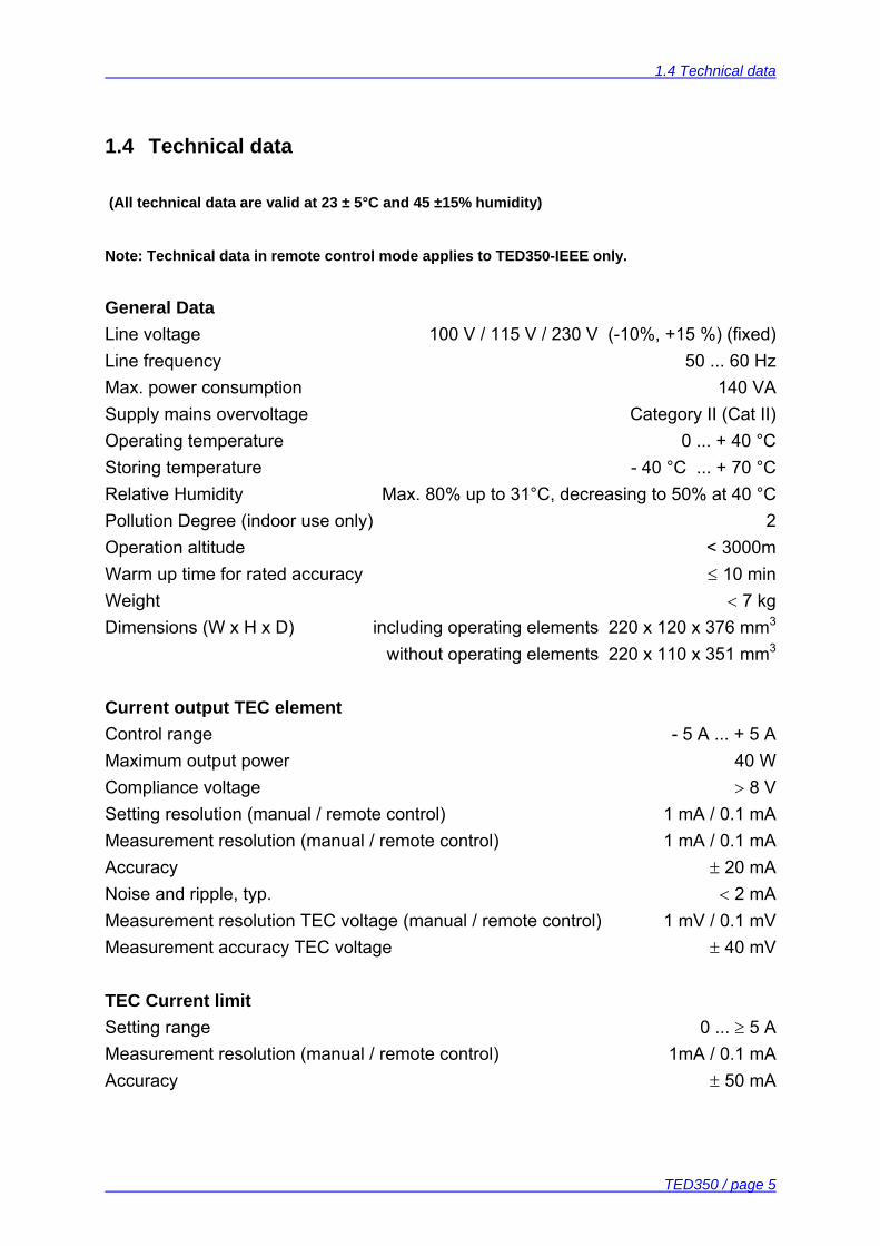
General Data Line voltage 100 V / 115 V / 230 V (-10%, +15 %) (fixed) Line frequency 50 ... 60 Hz Max. power consumption 140 VA Supply mains overvoltage Category II (Cat II) Operating temperature 0 ... + 40 °C Storing temperature - 40 °C ... + 70 °C Relative Humidity Max. 80% up to 31°C, decreasing to 50% at 40 °C Pollution Degree (indoor use only) 2 Operation altitude < 3000m Warm up time for rated accuracy ≤ 10 min Weight < 7 kg Dimensions (W x H x D) including operating elements 220 x 120 x 376 mm3 without operating elements 220 x 110 x 351 mm3 Current output TEC element Control range - 5 A ... + 5 A Maximum output power 40 W Compliance voltage > 8 V Setting resolution (manual / remote control) 1 mA / 0.1 mA Measurement resolution (manual / remote control) 1 mA / 0.1 mA Accuracy ± 20 mA Noise and ripple, typ. < 2 mA Measurement resolution TEC voltage (manual / remote control) 1 mV / 0.1 mV Measurement accuracy TEC voltage ± 40 mV TEC Current limit Setting range 0 ... ≥ 5 A Measurement resolution (manual / remote control) 1mA / 0.1 mA Accuracy ± 50 mA
1.4 Technical data
TED350 / page 6
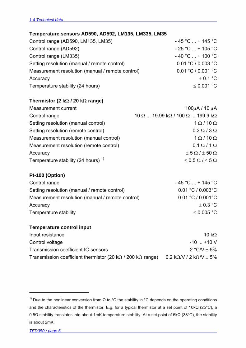
Temperature sensors AD590, AD592, LM135, LM335, LM35 Control range (AD590, LM135, LM35) - 45 °C ... + 145 °C Control range (AD592) - 25 °C ... + 105 °C Control range (LM335) - 40 °C ... + 100 °C Setting resolution (manual / remote control) 0.01 °C / 0.003 °C Measurement resolution (manual / remote control) 0.01 °C / 0.001 °C Accuracy ± 0.1 °C Temperature stability (24 hours) ≤ 0.001 °C Thermistor (2 kΩ / 20 kΩ range) Measurement current 100µA / 10 µA
Control range 10 Ω ... 19.99 kΩ / 100 Ω ... 199.9 kΩ
Setting resolution (manual control) 1 Ω / 10 Ω Setting resolution (remote control) 0.3 Ω / 3 Ω Measurement resolution (manual control) 1 Ω / 10 Ω Measurement resolution (remote control) 0.1 Ω / 1 Ω Accuracy ± 5 Ω / ± 50 Ω Temperature stability (24 hours) 1) ≤ 0.5 Ω / ≤ 5 Ω
Pt-100 (Option) Control range - 45 °C ... + 145 °C Setting resolution (manual / remote control) 0.01 °C / 0.003°C Measurement resolution (manual / remote control) 0.01 °C / 0.001°C Accuracy ± 0.3 °C Temperature stability ≤ 0.005 °C Temperature control input Input resistance 10 kΩ Control voltage -10 ... +10 V Transmission coefficient IC-sensors 2 °C/V ± 5% Transmission coefficient thermistor (20 kΩ / 200 kΩ range) 0.2 kΩ/V / 2 kΩ/V ± 5%
1) Due to the nonlinear conversion from Ω to °C the stability in °C depends on the operating conditions
and the characteristics of the thermistor. E.g. for a typical thermistor at a set point of 10kΩ (25°C), a
0.5Ω stability translates into about 1mK temperature stability. At a set point of 5kΩ (38°C), the stability
is about 2mK.
1.4 Technical data
TED350 / page 7
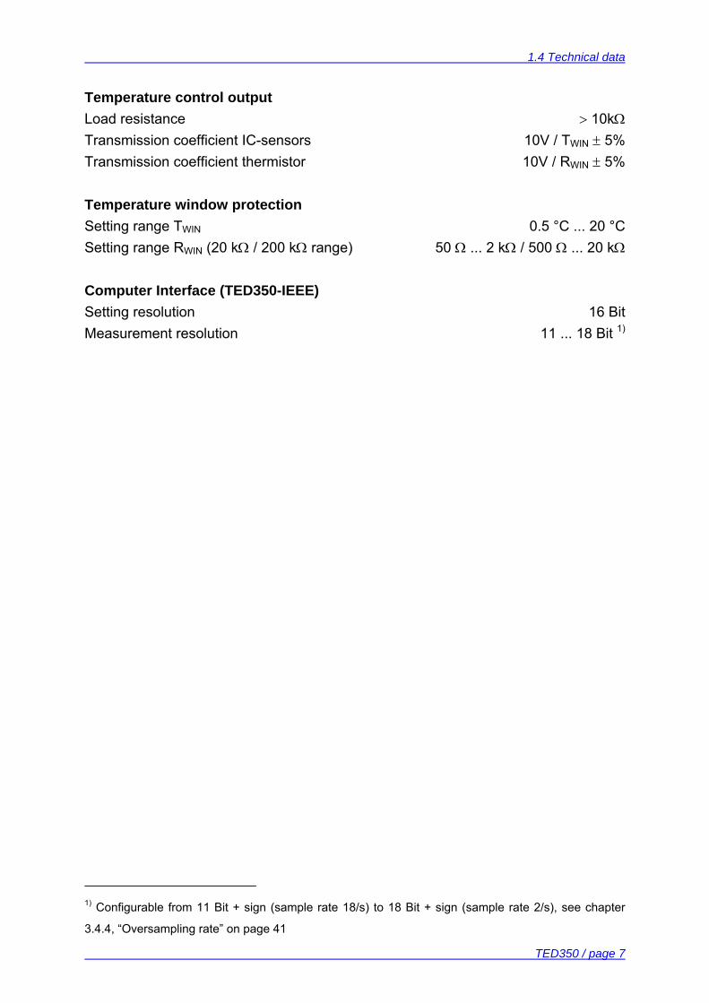
Temperature control output Load resistance > 10kΩ Transmission coefficient IC-sensors 10V / TWIN ± 5% Transmission coefficient thermistor 10V / RWIN ± 5% Temperature window protection Setting range TWIN 0.5 °C ... 20 °C Setting range RWIN (20 kΩ / 200 kΩ range) 50 Ω ... 2 kΩ / 500 Ω ... 20 kΩ Computer Interface (TED350-IEEE) Setting resolution 16 Bit Measurement resolution 11 ... 18 Bit 1)
1) Configurable from 11 Bit + sign (sample rate 18/s) to 18 Bit + sign (sample rate 2/s), see chapter
3.4.4, “Oversampling rate” on page 41
1.5 Operating elements
TED350 / page 8
1.5 Operating elements
1.5.1 Front panel
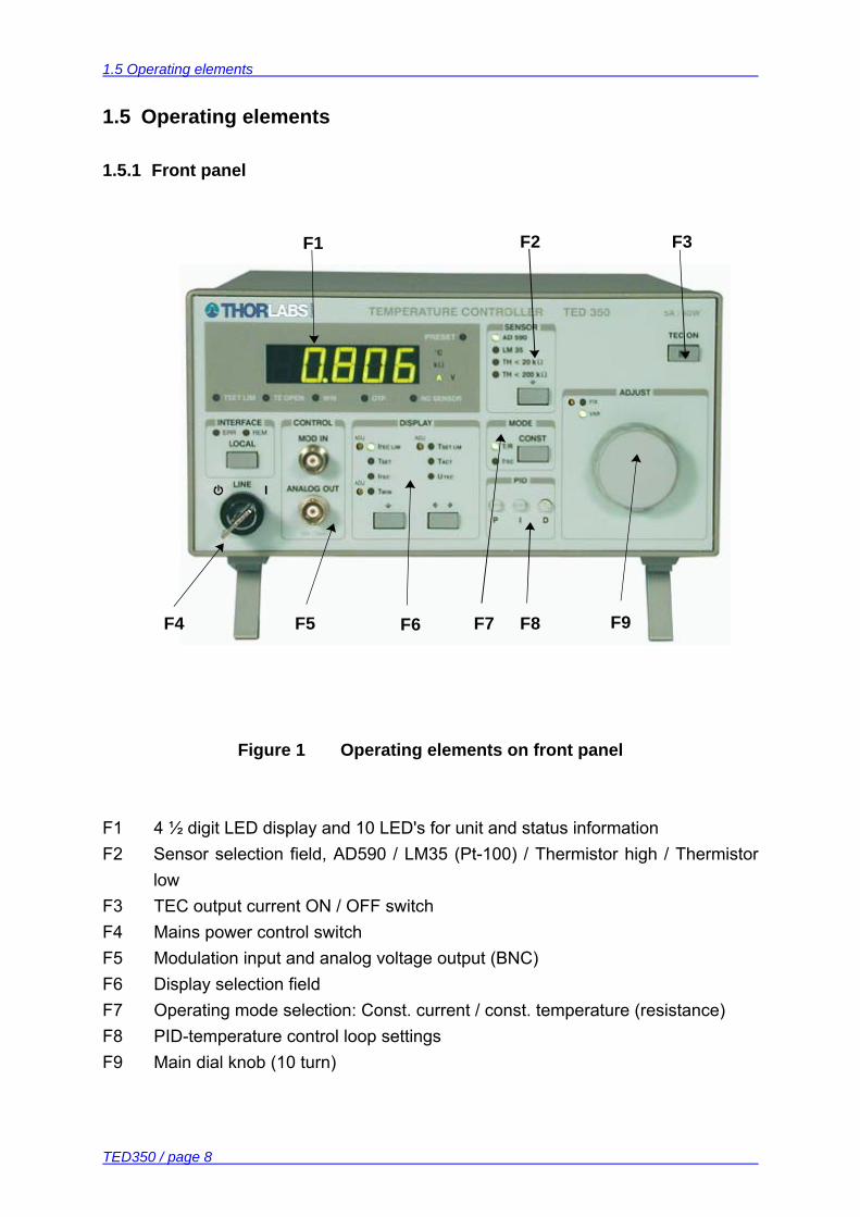
Figure 1 Operating elements on front panel
F1 4 ½ digit LED display and 10 LED's for unit and status information F2 Sensor selection field, AD590 / LM35 (Pt-100) / Thermistor high / Thermistor
low F3 TEC output current ON / OFF switch F4 Mains power control switch F5 Modulation input and analog voltage output (BNC) F6 Display selection field F7 Operating mode selection: Const. current / const. temperature (resistance) F8 PID-temperature control loop settings F9 Main dial knob (10 turn)
I I
F1 F2 F3
F4 F5 F6 F7 F8 F9
1.5 Operating elements
TED350 / page 9
1.5.2 Back panel
B1 B2 B3 B4
B5 B6 B7 B8 B9
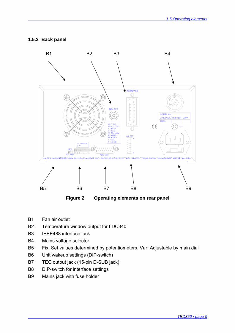
Figure 2 Operating elements on rear panel
B1 Fan air outlet B2 Temperature window output for LDC340 B3 IEEE488 interface jack B4 Mains voltage selector B5 Fix: Set values determined by potentiometers, Var: Adjustable by main dial B6 Unit wakeup settings (DIP-switch) B7 TEC output jack (15-pin D-SUB jack) B8 DIP-switch for interface settings B9 Mains jack with fuse holder
1.6 Pre-settings
TED350 / page 10
1.6 Pre-settings
To protect the TEC element and the other components of the setup the maximum allowed TEC current, the maximum temperature as well as an operating temperature window may be selected. 1.6.1 Setting the limit value of the TEC current
• Check the maximum allowed TEC current in the datasheet of your TEC element.
• Select the display ITEC LIM. • Change the limit value of the TEC current to the desired value with the
screwdriver-potentiometer besides the LED ITEC LIM. 1.6.2 Setting the maximum allowed temperature
To set the maximum allowed temperature (or the minimum allowed resistance): • Check the type of temperature sensor in your setup. • Select this sensor in the field marked “SENSOR“. • Select the display TSET LIM. • Change the limit value of the temperature (or resistance) to the desired value
with the screwdriver-potentiometer next to the LED TSET LIM. 1.6.3 Setting the temperature window
• Check the type of temperature sensor in your setup. • Select this sensor in the field marked “SENSOR“. • Select the display TWIN. • Change the size of the window to the desired value with the screwdriver-
potentiometer next to the LED TWIN. The display shows a “plusminus“ – value, so if you select i.e. 5.000°C the window will reach from 5°C below the set value to 5°C above the set value.
• Activate this function with DIP switch 4 (Refer to chapter 2.1.9 on page 22)
1.7 Connecting components
TED350 / page 11
1.7 Connecting components
1.7.1 Pin assignment of the output jack
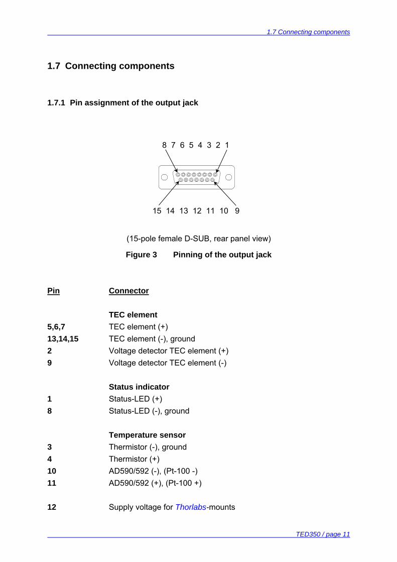
(15-pole female D-SUB, rear panel view)
Figure 3 Pinning of the output jack
Pin Connector TEC element 5,6,7 TEC element (+) 13,14,15 TEC element (-), ground 2 Voltage detector TEC element (+) 9 Voltage detector TEC element (-) Status indicator 1 Status-LED (+) 8 Status-LED (-), ground Temperature sensor 3 Thermistor (-), ground 4 Thermistor (+) 10 AD590/592 (-), (Pt-100 -) 11 AD590/592 (+), (Pt-100 +) 12 Supply voltage for Thorlabs-mounts
8 7 6 5 4 3 2 1
15 14 13 12 11 10 9
1.7 Connecting components
TED350 / page 12
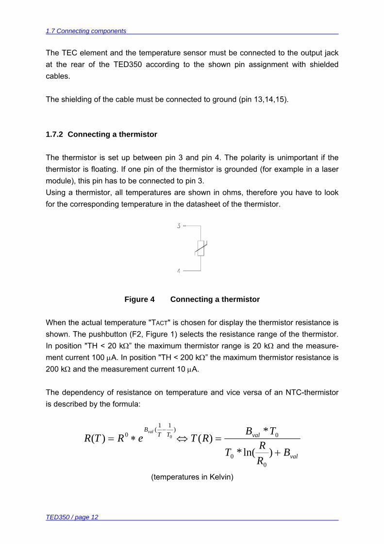
The TEC element and the temperature sensor must be connected to the output jack at the rear of the TED350 according to the shown pin assignment with shielded cables. The shielding of the cable must be connected to ground (pin 13,14,15). 1.7.2 Connecting a thermistor
The thermistor is set up between pin 3 and pin 4. The polarity is unimportant if the thermistor is floating. If one pin of the thermistor is grounded (for example in a laser module), this pin has to be connected to pin 3. Using a thermistor, all temperatures are shown in ohms, therefore you have to look for the corresponding temperature in the datasheet of the thermistor.
Figure 4 Connecting a thermistor
When the actual temperature "TACT" is chosen for display the thermistor resistance is shown. The pushbutton (F2, Figure 1) selects the resistance range of the thermistor. In position "TH < 20 kΩ” the maximum thermistor range is 20 kΩ and the measure-ment current 100 µA. In position "TH < 200 kΩ” the maximum thermistor resistance is 200 kΩ and the measurement current 10 µA. The dependency of resistance on temperature and vice versa of an NTC-thermistor is described by the formula:
val
valTTB
BRRT
TBRTeRTR
val
+=⇔∗=
−
)ln(*
*)()(
00
0)11(
0 0
(temperatures in Kelvin)
1.7 Connecting components
TED350 / page 13
with: R0: Thermistor nominal resistance at temperature T0
T0: Nominal temperature (typ. 298.15 K = 25°C) Bval: Energy constant For R0 and Bval refer to the data sheet of the thermistor. Evaluate the thermistor resistance for the desired set temperature. Select with the display selection keys (F2, Figure 1) the display value "TSET" to show the set value and set the evaluated resistance value with the tuning knob (F9). If the thermistor characteristic R(T) is given in the data sheet the desired resistance can be read directly.
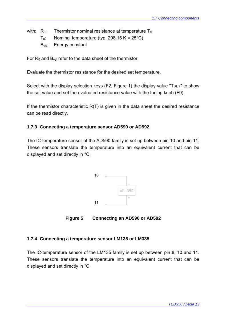
1.7.3 Connecting a temperature sensor AD590 or AD592
The IC-temperature sensor of the AD590 family is set up between pin 10 and pin 11. These sensors translate the temperature into an equivalent current that can be displayed and set directly in °C. 10
11
Figure 5 Connecting an AD590 or AD592
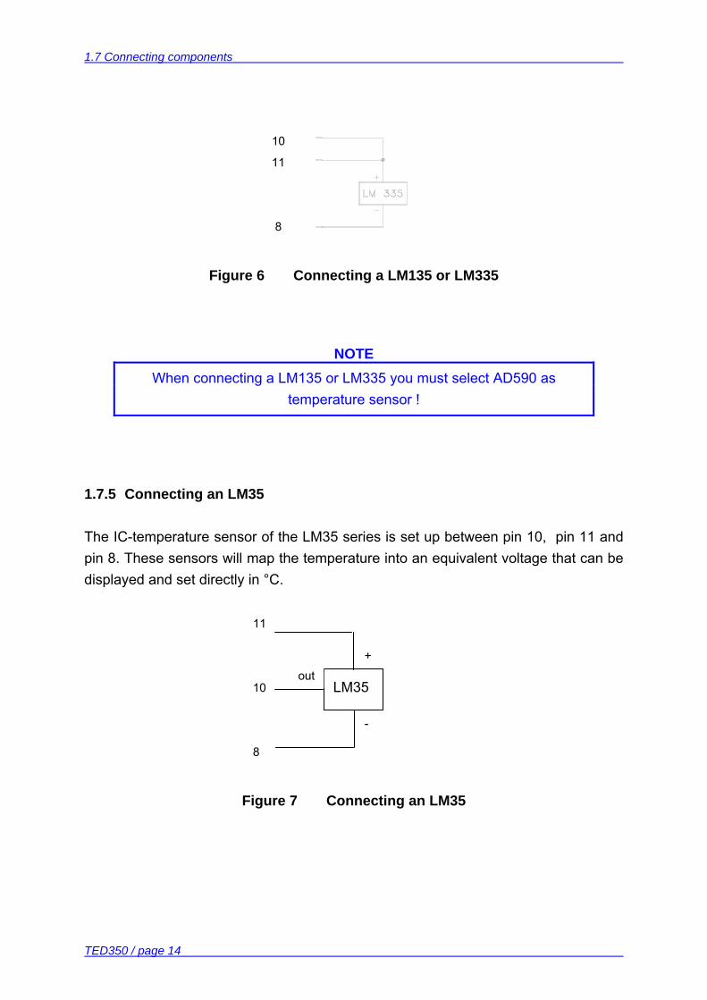
1.7.4 Connecting a temperature sensor LM135 or LM335
The IC-temperature sensor of the LM135 family is set up between pin 8, 10 and 11. These sensors translate the temperature into an equivalent current that can be displayed and set directly in °C.
1.7 Connecting components
TED350 / page 14
10
11
8
Figure 6 Connecting a LM135 or LM335
NOTE When connecting a LM135 or LM335 you must select AD590 as
temperature sensor !
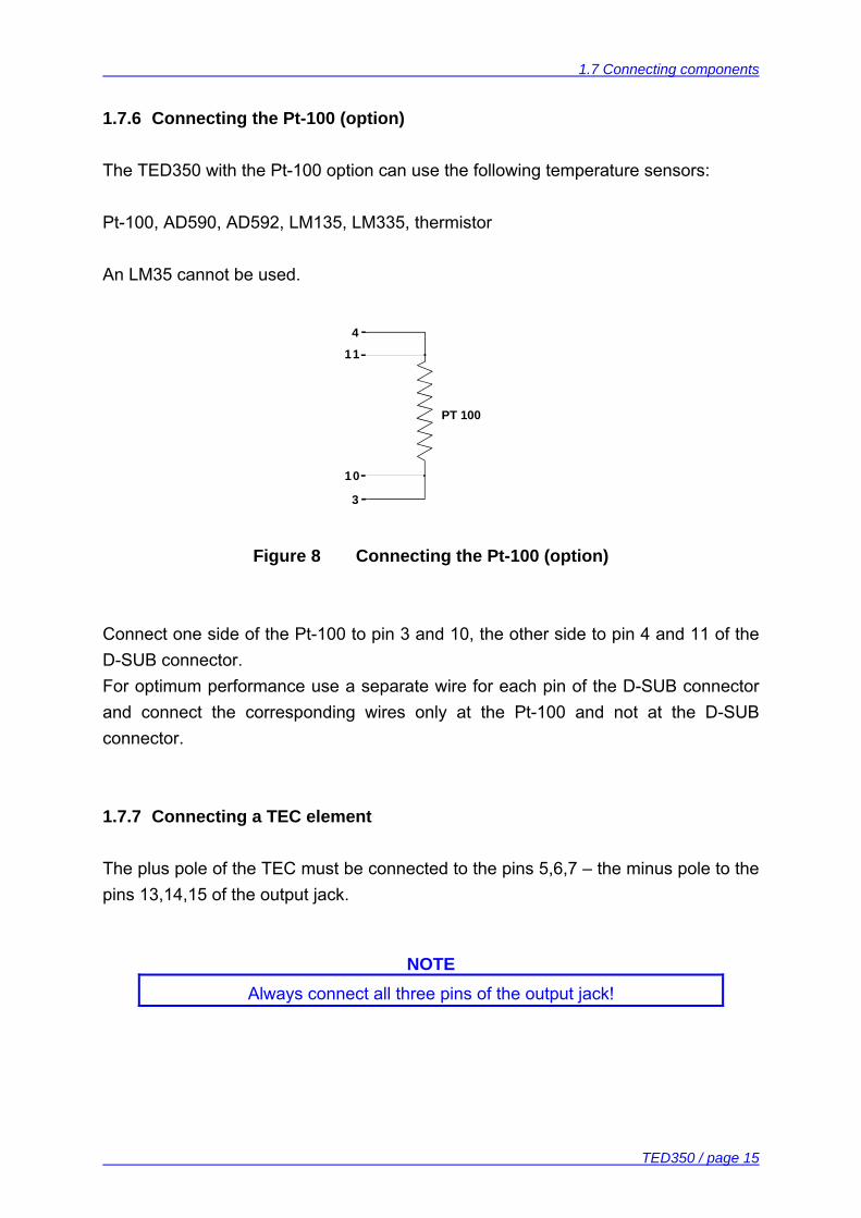
1.7.5 Connecting an LM35
The IC-temperature sensor of the LM35 series is set up between pin 10, pin 11 and pin 8. These sensors will map the temperature into an equivalent voltage that can be displayed and set directly in °C. 11
10
8
Figure 7 Connecting an LM35
LM35 out
-
+
1.7 Connecting components
TED350 / page 15
1.7.6 Connecting the Pt-100 (option)
The TED350 with the Pt-100 option can use the following temperature sensors: Pt-100, AD590, AD592, LM135, LM335, thermistor An LM35 cannot be used.
Figure 8 Connecting the Pt-100 (option)
Connect one side of the Pt-100 to pin 3 and 10, the other side to pin 4 and 11 of the D-SUB connector. For optimum performance use a separate wire for each pin of the D-SUB connector and connect the corresponding wires only at the Pt-100 and not at the D-SUB connector. 1.7.7 Connecting a TEC element
The plus pole of the TEC must be connected to the pins 5,6,7 – the minus pole to the pins 13,14,15 of the output jack.
NOTE Always connect all three pins of the output jack!
4
11
10
3
PT 100
1.7 Connecting components
TED350 / page 16
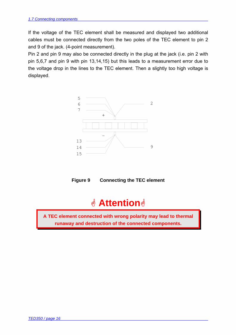
If the voltage of the TEC element shall be measured and displayed two additional cables must be connected directly from the two poles of the TEC element to pin 2 and 9 of the jack. (4-point measurement). Pin 2 and pin 9 may also be connected directly in the plug at the jack (i.e. pin 2 with pin 5,6,7 and pin 9 with pin 13,14,15) but this leads to a measurement error due to the voltage drop in the lines to the TEC element. Then a slightly too high voltage is displayed.
13
1514
-
7
56
+
9
2
Figure 9 Connecting the TEC element
Attention A TEC element connected with wrong polarity may lead to thermal
runaway and destruction of the connected components.
1.7 Connecting components
TED350 / page 17
1.7.7.1 Polarity check of the TEC element
• Connect TEC element and temperature sensor. The sensor must have good thermal contact to the active surface of the TEC element.
• Switch on the TED350. Now follow the steps described in chapter 1.6, “Pre-settings“ on page 10.
• Select the display TSET and select a suitable temperature (resistance). • Select the display TACT. • Switch on the output (press TEC ON) and observe the actual temperature
(resistance).
If the temperature TACT is continually running away from TSET the TEC element is reverse connected. Change the polarity and repeat the procedure.
If TACT is settling up and down evenly around the value TSET the TEC element is connected correctly however the values for the P-, I- and D-share of the control loop are still incorrect. (Refer to chapter 2.2.2, "PID adjustment" starting on page 26)
If TACT is settling properly to the value TSET the TEC element is connected correctly but the values for the P-, I- and D-share of the control loop might still be improved.
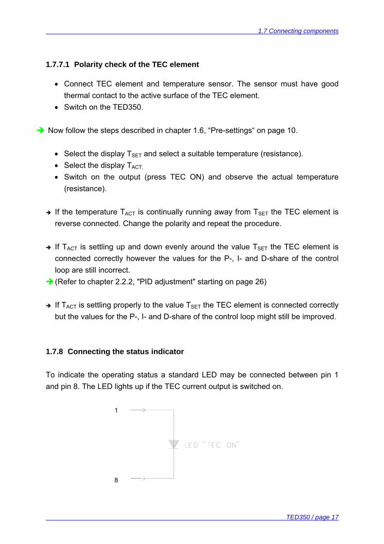
1.7.8 Connecting the status indicator
To indicate the operating status a standard LED may be connected between pin 1 and pin 8. The LED lights up if the TEC current output is switched on. 1
8

1.7 Connecting components
TED350 / page 18
Poling and value of the TEC current is insignificant here. 1.7.9 Fine tuning of the temperature
The TED350 has an input for fine tuning of the temperature labeled MOD IN. The voltage at this input modifies the set value of the temperature (AD590/LM35/LM335-mode) or of the thermistor resistance (thermistor mode). The purpose is for example to stabilize the wavelength of laser diodes in closed control loops (wavelength locker). The input has no low frequency limit. If a DC-voltage is applied a constant deviation from the set temperature can be achieved. The upper frequency limit depends on the thermal setup especially on the thermal load. It will be in the range of some Hertz. When fine tuning the temperature all protection circuits remain active so that the TEC element is run absolutely safe. The MOD IN input is specified for voltages from -10V ... +10V.

2.1 Manual operation
TED350 / page 19
2 Operating the TED350
2.1 Manual operation
Attention Prior to switch on your TED350 please check if the line voltage set
with the voltage selector at the rear panel corresponds to your mains voltage!
2.1.1 Selecting the sensor
Three different types of sensors can be selected:
• AD590 family • LM35 family (Pt-100 for TED350 with Pt-100 option) • Thermistor (low range) • Thermistor (high range)
A LED indicates the selected sensor. 2.1.1.1 The Pt-100 option
Select the LM35 as sensor. The Pt-100 is operated with a constant current of 1 mA flowing from pin 4 to pin 3. The display shows the temperature in °C with an accuracy of 1°C over the range –10°C ... +100°C. The setting range is about –45°C to +145°C.
2.1 Manual operation
TED350 / page 20
2.1.2 Selecting the mode of operation
Two modes of operation are possible
• Constant temperature (resistance) mode • Constant TEC current mode
A LED indicates the selected mode. 2.1.3 Selecting the displayed value
Seven different values can be displayed:
• Maximum allowed TEC current ITEC LIM • Set temperature (resistance) TSET • TEC current ITEC • Size of the temperature window TWIN • Maximum allowed temperature (minimum (!) allowed resistance ) TSET LIM • Actual temperature (resistance) TACT • TEC voltage UTEC
A LED indicates the selected display.
NOTE In constant TEC current mode some values (i.e. TSET ) are not defined and
can not be displayed or even selected.
With the output switched off and the display ITEC selected the LED “PRESET“ indicates that the set value of the TEC current is displayed.
2.1 Manual operation
TED350 / page 21
2.1.4 The output ANALOG OUT
This output offers a voltage in strict correlation to the difference between actual and set temperature, scaled to the set temperature window. The upper border of the temperature window yields + 10 V output and the lower border -10 V. Example: If the set temperature is 20 °C and the temperature window is set to 5 °C an actual temperature of 15 °C leads to -10V at the output 20 °C leads to 0 V at the output 25 °C leads to +10 V at the output . . . 2.1.5 Switching the output ON and OFF
With the button TEC ON the TEC current is switched on or off. The LED inside this button indicates the state of the output. 2.1.6 Setting the PID shares
(Refer to chapter 2.2, “Optimization of temperature control loops“ starting on page 24) 2.1.7 WIN OUT
This jack can be used to supervise the temperature of a laser diode when using a Thorlabs LDC340 laser diode driver. Simply connect the corresponding jack of the LDC340 to this output of the TED350. Further details can be found in the operation manual of the LDC340.
2.1 Manual operation
TED350 / page 22
2.1.8 Fix / Var selector
This switch selects whether the set value (temperature, resistance or TEC current) is set by turning the main dial knob (Var) or by the screwdriver potentiometer next to the LED marked “FIX“. The two LEDs marked “VAR“ and “FIX“ located on the front panel indicate the position of this switch. If the switch position is changed during TEC ON the TEC output will be switched off automatically. 2.1.9 Wakeup setting DIP switch
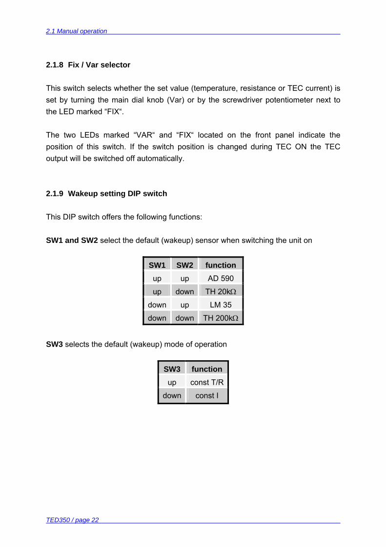
This DIP switch offers the following functions: SW1 and SW2 select the default (wakeup) sensor when switching the unit on
SW1 SW2 function up up AD 590
up down TH 20kΩ
down up LM 35
down down TH 200kΩ
SW3 selects the default (wakeup) mode of operation
SW3 function up const T/R
down const I
2.1 Manual operation
TED350 / page 23
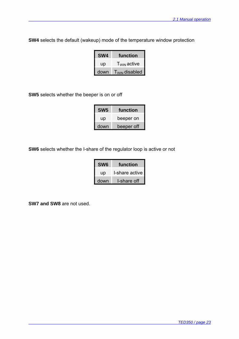
SW4 selects the default (wakeup) mode of the temperature window protection
SW4 function up TWIN active
down TWIN disabled
SW5 selects whether the beeper is on or off
SW5 function up beeper on
down beeper off
SW6 selects whether the I-share of the regulator loop is active or not
SW6 function up I-share active
down I-share off
SW7 and SW8 are not used.
2.2 Optimization of temperature control loops
TED350 / page 24
2.2 Optimization of temperature control loops
2.2.1 Setup and function of temperature controllers
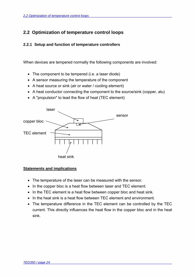
When devices are tempered normally the following components are involved:
• The component to be tempered (i.e. a laser diode) • A sensor measuring the temperature of the component • A heat source or sink (air or water / cooling element) • A heat conductor connecting the component to the source/sink (copper, alu) • A "propulsion" to lead the flow of heat (TEC element)
laser sensor copper bloc TEC element heat sink Statements and implications
• The temperature of the laser can be measured with the sensor. • In the copper bloc is a heat flow between laser and TEC element. • In the TEC element is a heat flow between copper bloc and heat sink. • In the heat sink is a heat flow between TEC element and environment. • The temperature difference in the TEC element can be controlled by the TEC
current. This directly influences the heat flow in the copper bloc and in the heat sink.
2.2 Optimization of temperature control loops
TED350 / page 25
So the temperature of the laser can be influenced by the TEC current. The quantity of heat to flow from the laser into the copper bloc and the size of the block effects the reaction speed of the setup.
Usually very small components (laser diodes) are tempered with relatively extensive cooling elements (TEC elements). Thus the dissipated power must be lead away quickly and simultaneously the components are to be kept as far as possible at the same temperature. Demands to the ideal temperature control loop 1. Knowledge of the absolute laser temperature 2. Stability of the laser temperature under any influence 3. Immediate settling to a new laser temperature when changing the set value of the
temperature Influences on the real temperature control loop To 1: Offset and gain errors of the sensor will only allow a relative knowledge of the
laser temperature. The sensor is never fixed to the laser chip in such a way that it will exclusively
measure its temperature. So the temperature in the copper bloc being inho-mogeneous due to the heat flow is measured as well. Even within the laser chip the temperature is not homogeneous.
Possibility of optimization: sensor calibration To 2. If the internal power dissipation changes (e.g. the laser current is changed)
then also the temperature gradient between laser and sensor changes. This results in a measurement error depending on the mechanical setup la-ser/sensor. Changes in the ambient temperature however will be compensated well by the control loop since they will almost only have an effect on the heat slope between TEC element and cooling element.
Possibility of optimization: best possible thermal design
2.2 Optimization of temperature control loops
TED350 / page 26
To 3. The transient response by setting a new temperature is limited since the heat
transport in the copper bloc is relatively slow. Furthermore the temperature slope in the copper must form anew. The sensor (which also possesses a significant heat capacity) must settle to the laser temperature.
Possibility of optimization: PID adjustment 2.2.2 PID adjustment
Temperature control loops are comparatively slow control loops with control oscillations in the Hertz range. PID adjustment optimizes the dynamic behavior. With the TED350 the three parameters P, I and D can be selected independently. Example of a PID adjustment (Preconditions: All limit values, all polarities have been set correctly, a suitable sensor is connected and selected, the ambient temperature is about 20 °C) 1. Set the P- and D-share to 0 (7 o'clock) 2. Switch off the I-share (SW6 of the DIP switch on the rear). (Refer to chapter 2.1.9, "Wakeup setting DIP switch" starting on page 22) 3. Switch on the output (button TEC ON) and observe the actual temperature. P-share 4. Change repeatedly between set temperatures of about 18 °C and 22 °C while
observing the settling behavior of the actual temperature. Increase the P-share gradually by turning the corresponding potentiometer
clockwise. Higher values increase the settling speed but the same time the stability reserve is decreased so that number and amplitude of overshoots increases.
2.2 Optimization of temperature control loops
TED350 / page 27
The P-share is set correctly when the actual temperature remains stable on a value near to the set temperature after only 2-3 overshoots.
D-share 5. Change repeatedly between set temperatures of about 18 °C and 22 °C while
observing the settling behavior of the actual temperature. Increase the D-share gradually by turning the corresponding potentiometer
clockwise. Higher values will decrease the amplitude of the overshoots.
The D-share has been set correctly when the actual temperature remains stable on a value near the set temperature after a minimum of overshoots.
I-share 6. Switch on the I-share again (SW6 of the DIP switch on the rear) (Refer to chapter 2.1.9, "Wakeup setting DIP switch" starting on page 22) 7. Again change repeatedly between set temperatures of about 18 °C and 22 °C
while observing the settling behavior of the actual temperature. Increase the I-share gradually by turning the corresponding potentiometer
clockwise. Higher values will accelerate the settling to the set temperature.
The I-share has been set correctly when the actual temperature settles optimally to the set temperature.
2.2 Optimization of temperature control loops
TED350 / page 28
3 Communication with a control computer (TED350-IEEE)
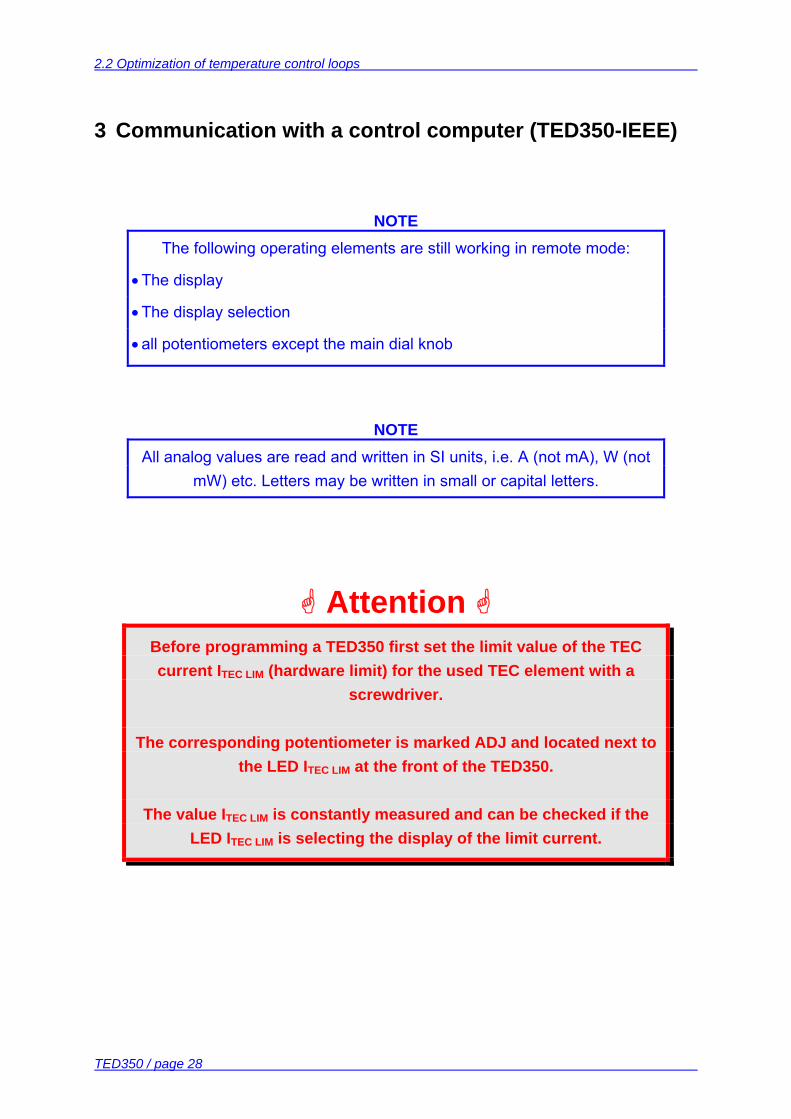
NOTE The following operating elements are still working in remote mode:
• The display
• The display selection
• all potentiometers except the main dial knob
NOTE All analog values are read and written in SI units, i.e. A (not mA), W (not
mW) etc. Letters may be written in small or capital letters.
Attention
Before programming a TED350 first set the limit value of the TEC current ITEC LIM (hardware limit) for the used TEC element with a
screwdriver.
The corresponding potentiometer is marked ADJ and located next to the LED ITEC LIM at the front of the TED350.
The value ITEC LIM is constantly measured and can be checked if the LED ITEC LIM is selecting the display of the limit current.
3.1 IEEE488 interface (TED350-IEEE)
TED350 / page 29
3.1 IEEE488 interface (TED350-IEEE)
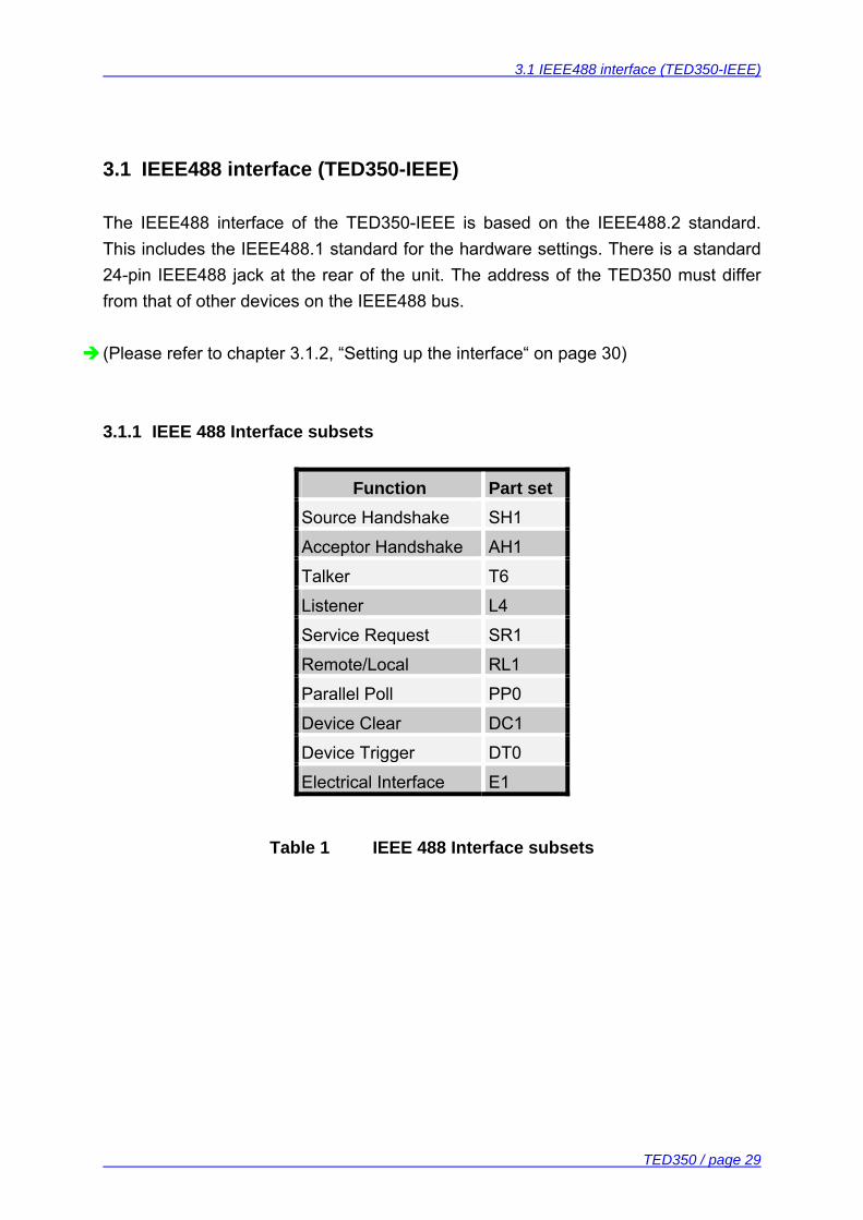
The IEEE488 interface of the TED350-IEEE is based on the IEEE488.2 standard. This includes the IEEE488.1 standard for the hardware settings. There is a standard 24-pin IEEE488 jack at the rear of the unit. The address of the TED350 must differ from that of other devices on the IEEE488 bus. (Please refer to chapter 3.1.2, “Setting up the interface“ on page 30) 3.1.1 IEEE 488 Interface subsets
Function Part set Source Handshake SH1
Acceptor Handshake AH1
Talker T6
Listener L4
Service Request SR1
Remote/Local RL1
Parallel Poll PP0
Device Clear DC1
Device Trigger DT0
Electrical Interface E1
Table 1 IEEE 488 Interface subsets
3.1 IEEE488 interface (TED350-IEEE)
TED350 / page 30
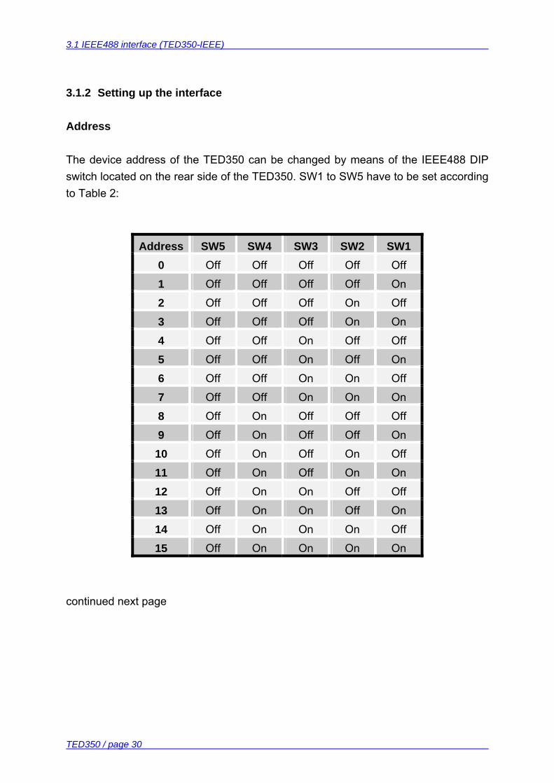
3.1.2 Setting up the interface
Address The device address of the TED350 can be changed by means of the IEEE488 DIP switch located on the rear side of the TED350. SW1 to SW5 have to be set according to Table 2:
Address SW5 SW4 SW3 SW2 SW1 0 Off Off Off Off Off
1 Off Off Off Off On
2 Off Off Off On Off
3 Off Off Off On On
4 Off Off On Off Off
5 Off Off On Off On
6 Off Off On On Off
7 Off Off On On On
8 Off On Off Off Off
9 Off On Off Off On
10 Off On Off On Off
11 Off On Off On On
12 Off On On Off Off
13 Off On On Off On
14 Off On On On Off
15 Off On On On On
continued next page
3.1 IEEE488 interface (TED350-IEEE)
TED350 / page 31
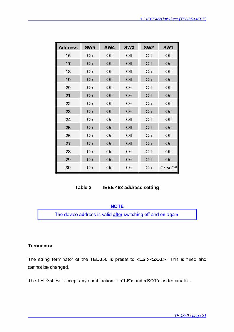
Address SW5 SW4 SW3 SW2 SW1 16 On Off Off Off Off
17 On Off Off Off On
18 On Off Off On Off
19 On Off Off On On
20 On Off On Off Off
21 On Off On Off On
22 On Off On On Off
23 On Off On On On
24 On On Off Off Off
25 On On Off Off On
26 On On Off On Off
27 On On Off On On
28 On On On Off Off
29 On On On Off On
30 On On On On On or Off
Table 2 IEEE 488 address setting
NOTE The device address is valid after switching off and on again.
Terminator The string terminator of the TED350 is preset to <LF><EOI>. This is fixed and cannot be changed. The TED350 will accept any combination of <LF> and <EOI> as terminator.
3.1 IEEE488 interface (TED350-IEEE)
TED350 / page 32
3.1.3 Connecting the PC
• Connect the TED350-IEEE and the PC to the line • Connect both units with a shielded IEEE488 cable • Switch on all units at the bus and the control computer
To guarantee a safe transmission of data the IEEE488 cable between two units should not be longer than 2 meters and the total cable length should not exceed 20 meters. The TED350-IEEE will automatically enter REMOTE mode after the first character is transferred.
NOTE Programming the control software will vary with the type of computer, the user interface, the programming language, the interface card used as well
as with the driver software and the correspondingly supplied software interfaces. Please refer to the documentation of these components.
(Also refer to chapter 3.9, "Hints for setting up control programs" on page 60)
3.1 IEEE488 interface (TED350-IEEE)
TED350 / page 33
3.1.4 IEEE488 bus commands
To communicate via the IEEE488 bus the standard control signals [MLA], [MTA], [UNL], [UNT], [ATN], [REN], [SPE], [SPD] are used. If the control program for the TED350 is written in a basic language as e.g. BASIC these IEEE488 control signals are automatically transmitted to the TED350 according to the used driver software and do not have to be explicitly produced in the control program. Also in the LabVIEW®- or LabWindows/CVI®-drivers from Thorlabs these functions are implemented. When receiving the IEEE488 bus commands [GET], [LLO], [GTL], [DCL] or [SDC] the TED350 executes the following functions: [LLO] Local Lockout The command [LLO] disables the button . Return to LOCAL mode (manual operation) is only possible with the command [GTL] (see below). [GTL] Go To Local The command [GTL] switches the TED350-IEEE into LOCAL mode (manual operation). The previously set values for laser current, laser power etc. will no more be valid. The set values are determined by the main dial knob.
3.1 IEEE488 interface (TED350-IEEE)
TED350 / page 34
[DCL] Device Clear The command [DCL] switches off the output and sets back all values that are usually set back when switching the unit on. The TED350 will behave as if it has been switched on anew but will be in REMOTE mode.
NOTE The command [DCL] sets back all units connected to the IEEE488 bus.
[SDC] Selected Device Clear The command [SDC] switches the output off and sets back all values that are usually set back when switching the unit on. The TED350 will behave as if it has been switched on anew but will be in REMOTE mode.
NOTE In contrast to the command [DCL] the command [SDC] only sets back
the device addressed.
3.2 Before Programming
TED350 / page 35
3.2 Before Programming
3.2.1 Nomenclature
Program messages (PC ⇒ TED350) are written in inverted commas: "*IDN?" Response messages (TED350 ⇒ PC) are written in brackets: [MODE CC] There is a decimal point: 1.234 Parameters are separated with comma: "PLOT 2,0" 3.2.2 Program and response messages
Blocks of message data are transferred between the controller and the TED350 during communications. Messages sent from the controller to the TED350 are called program messages and messages sent back from the TED350 to the controller are called response messages. If a program message contains a query command i.e. a command which requests a response the TED350 returns a response message. Program messages With program messages settings are done (command) at the TED350 and response messages are selected (query). Program messages can be separated by semicolon. All program messages are executed sequentially (one after the other). Examples: ":MODE CC" selecting the mode “constant current“ (command) "*IDN?" requesting the identification (query) ":SENS AD;:MODE CC" selecting the temperature sensor and the operating
mode. Response messages With response messages measurement values and status informations are transferred to the PC. All response messages are generated when the query (program message) is parsed. Example: [:ITE:ACT 7.123456E-01] measuring the actual TEC current
3.2 Before Programming
TED350 / page 36
3.2.3 Data format
According to the IEEE488.2 specifications all data variables are divided into 4 different data formats: Character response data (<CRD>) Is a single character or a string. Examples: A or ABGRS or A125TG or A1.23456A (Refer to IEEE488.2-1992 standard, chapter 8.7.1) Numeric response data Type 1 (<NR1>) Is a numerical value with sign in integer notation. Examples: 1 or +1 or -22 or 14356789432 (Refer to IEEE488.2-1992 standard, chapter 8.7.2) Numeric response data Type 2 (<NR2>) Is a numerical value with or without sign in floating point notation without exponent. Examples: 1.1 or +1.1 or -22.1 or 14356.789432 (Refer to IEEE488.2-1992 standard, chapter 8.7.3) Numeric response data Type 3 (<NR3>) Is a numerical value with or without sign in floating point notation with signed exponent. Examples: 1.1E+1 or +1.1E-1 or -22.1E+1 or 143.56789432E+306 (Refer to IEEE488.2-1992 standard, chapter 8.7.4)
3.3 Common commands and queries
TED350 / page 37
3.3 Common commands and queries
The common commands are independent of the instrument’s functions and are specified in the IEEE488.2 standard. 3.3.1 Identification query
Syntax: "*IDN?" Response: [PROFILE, TED350, 0, 2.17] Description: A reply consists of the following sequence: <Manufacturer>, <Model>, <Serial No.>, <Firmware version> 3.3.2 Reset
Syntax: "*RST" Description: All set values will be reset to the default values. The output is switched
off. 3.3.3 Self-test query
Syntax: "*TST?" Response: [0] Description: 0: Self-test finished successful. 3.3.4 Set Operation-complete bit
Syntax: "*OPC" Description: The TED350 sets the OPC-bit in the Standard-Event-Status-Register.

3.3 Common commands and queries
TED350 / page 38
3.3.5 Operation-complete query
Syntax: "*OPC?" Response: [1] Description: 1: Operation completed. 3.3.6 Wait
Syntax: "*WAI" Description: The TED350 will wait until the last operation is completed. 3.3.7 Event-Status-Enable-Register (ESE)
Programming: Syntax: "*ESE <NR1>" Valid Range: 0..255 Default Value: 0 Description: Sets the Event-Status-Enable-Register (ESE). Reading: Syntax: "*ESE?" Response: [<NR1>] Description: Queries the Event-Status-Enable-Register (ESE) and returns the
content in decimal notation. The content is not modified. 3.3.8 Query Standard-Event-Status-Register (ESR)
Syntax: "*ESR?" Response: [<NR1>] Description: Queries the Standard-Event-Status-Register (ESR) and returns the
content in decimal notation. The content is cleared.
3.3 Common commands and queries
TED350 / page 39
3.3.9 Service-Request-Enable-Register (SRE)
Programming: Syntax: "*SRE <NR1>" Valid Range: 0..255 Default Value: 0 Description: Sets the Service-Request-Enable-Register (SRE). Reading: Syntax: "*SRE?" Response: [<NR1>] Description: Queries the Service-Request-Enable-Register (ESE) and returns the
content in decimal notation. The content is not modified. 3.3.10 Query Status-Byte-Register (STB)
Syntax: "*STB?" Response: [<NR1>] Description: Queries the Status-Byte-Register (STB) and returns the content in
decimal notation. Bit 6 (MSS) is set to 0 the other bits are kept un-changed.
3.4 System command group
TED350 / page 40
3.4 System command group
3.4.1 Answer mode
Programming: Syntax: ":SYST:ANSW FULL" ":SYST:ANSW VALUE" Default Value: FULL Description: When switched to "VALUE" the TED350 sends only the requested
parameter without designator. Example: When requesting the actual TEC current with ":ITE:ACT?" the
TED350 will only send [5.123456E-02] instead of [:ITE:ACT 5.123456E-02]. This is not according to the
IEEE488.2 standard but useful if you want to increase speed. Reading: Syntax: ":SYST:ANSW?" Response: [:SYST:ANSW FULL] [:SYST:ANSW VALUE] Description: Queries the answer mode. 3.4.2 Error-LED mode
Programming: Syntax: ":SYST:ERRLED OFF" ":SYST:ERRLED ON" Default Value: OFF Description: When switched to "ON" the interface ERRor LED lights as long as
there are errors in the error queue. When switched to "OFF" the in-terface ERRor LED is dark.
Reading: Syntax: ":SYST:ERRLED?" Response: [:SYST:ERRLED OFF] [:SYST:ERRLED ON] Description: Queries the Error-LED mode.
3.4 System command group
TED350 / page 41
3.4.3 Querying the error queue
Syntax: ":SYST:ERR?" Response: [0, "No Error"] Description: Queries the error queue of the TED350. The reply consists of the
following sequence: <Error No.>, "<Error text>". If the error queue is empty: [0, "No error"] will response.
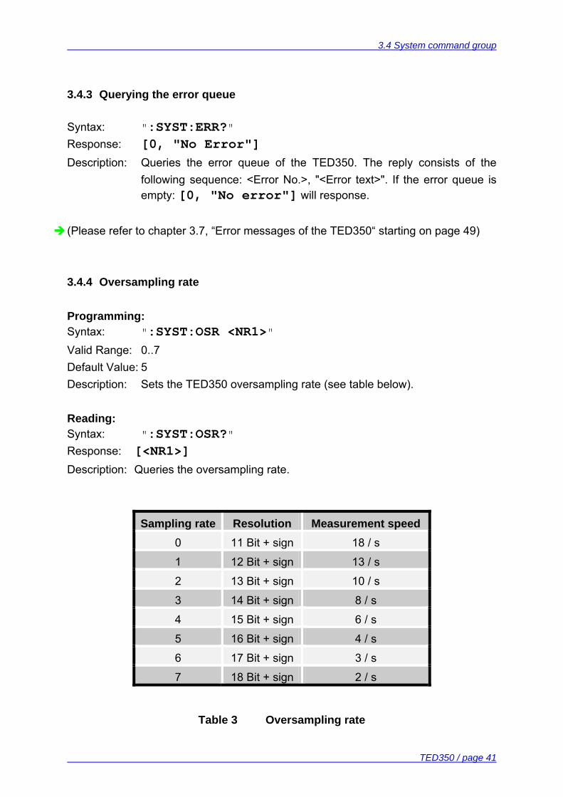
(Please refer to chapter 3.7, “Error messages of the TED350“ starting on page 49) 3.4.4 Oversampling rate
Programming: Syntax: ":SYST:OSR <NR1>" Valid Range: 0..7 Default Value: 5 Description: Sets the TED350 oversampling rate (see table below). Reading: Syntax: ":SYST:OSR?" Response: [<NR1>] Description: Queries the oversampling rate.
Sampling rate Resolution Measurement speed 0 11 Bit + sign 18 / s
1 12 Bit + sign 13 / s
2 13 Bit + sign 10 / s
3 14 Bit + sign 8 / s
4 15 Bit + sign 6 / s
5 16 Bit + sign 4 / s
6 17 Bit + sign 3 / s
7 18 Bit + sign 2 / s
Table 3 Oversampling rate
3.5 Status command group
TED350 / page 42
3.5 Status command group
(Refer to chapter 3.8, “Status reporting“ on page 53) 3.5.1 Query Device-Error-Condition-Register (DEC)
Syntax: ":STAT:DEC?" Response: [<NR1>] Description: Queries the Device-Error-Condition-Register (DEC) and returns the
content in decimal notation. The content is not modified. 3.5.2 Query Device-Error-Event-Register (DEE)
Syntax: ":STAT:DEE?" Response: [<NR1>] Description: Queries the Device-Error-Event-Register (DEE) and returns the
content in decimal notation. The content is cleared. 3.5.3 Device-Error-Event-Enable-Register (EDE)
Programming: Syntax: ":STAT:EDE <NR1>" Valid Range: 0...65535 Default Value: 0 Description: Sets the Device-Error-Event-Enable-Register (EDE). Reading: Syntax: ":STAT:EDE?" Response: [<NR1>] Description: Queries the Device-Error-Event-Enable-Register (EDE) and returns
the content in decimal notation. The content is not modified.
3.6 TED350 specific commands
TED350 / page 43
3.6 TED350 specific commands
3.6.1 Temperature sensor (SENS)
Programming: Syntax: ":SENS AD" (AD590 family) ":SENS LM" (LM35 family or Pt-100 option) ":SENS THL" (thermistor, 20 kΩ range) ":SENS THH" (thermistor, 200 kΩ range) Assumption: The TEC output is switched off. Description: Selects the type of temperature sensor. Sets the programmed
temperature / resistance / current to default values. Reading: Syntax: ":SENS?" Response: [:SENS AD] [:SENS LM] [:SENS THL] [:SENS THH] Description: Queries the type of temperature sensor. 3.6.2 Operation mode (MODE)
Programming: Syntax: ":MODE CC" (constant current) ":MODE CT" (constant temperature / resistance) Assumption: The TEC output is switched off. Description: Selects the mode of operation. Sets the programmed temperature /
resistance / current to default values. Reading: Syntax: ":MODE?" Response: [:MODE CC] [:MODE CT] Description: Queries the mode of operation.
3.6 TED350 specific commands
TED350 / page 44
3.6.3 Switching the TEC on and off (TEC)
Programming: Syntax: ":TEC OFF" ":TEC ON" Default Value: OFF Assumption: To switch the TEC on there must be no device errors (no sensor, tec
open, over temperature, ...). Description: Switches the TEC output on or off. Reading: Syntax: ":TEC?" Response: [:TEC OFF] [:TEC ON] Description: Queries the state of the TEC output. 3.6.4 Reading the TEC current hardware limit (LIMTP)
Syntax: ":LIMTP:ACT?" Response: [:LIMTP:ACT <NR3>] Description: Queries the actual TEC current hardware-limit. Unit: [A] (Refer to Chapter 1.6.1, "Setting the limit value of the TEC current" on page 10) 3.6.5 Reading the TEC temperature / resistance hardware limit (LIMTR)
Syntax: ":LIMTR:ACT?" Response: [:LIMTR:ACT <NR3>] Description: Queries the actual TEC temperature / resistance hardware-limit. Unit: [A] (Refer to Chapter 1.6.2, "Setting the maximum allowed temperature" on page 10)
3.6 TED350 specific commands
TED350 / page 45
3.6.6 Temperature (only AD590 and LM35) (TEMP)
Programming: Syntax: ":TEMP:SET <NR3>" Valid Range: Depends on the instrument type. Default Value: 25 °C Assumption: The temperature sensor is set to AD590 or LM35. The operating mode
is set to constant temperature / resistance. Description: Sets the TEC temperature. Unit: [°C]. Reading the set temperature: Syntax: ":TEMP:SET?" Response: [:TEMP:SET <NR3>] Assumption: The temperature sensor is set to AD590 or LM35. Description: Queries the programmed temperature. Unit: [°C]. Reading the minimum temperature: Syntax: ":TEMP:MIN?" Response: [:TEMP:MIN <NR3>] Assumption: The temperature sensor is set to AD590 or LM35. Description: Queries the minimum allowed temperature. Unit: [°C]. Reading the maximum temperature: Syntax: ":TEMP:MAX?" Response: [:TEMP:MAX <NR3>] Assumption: The temperature sensor is set to AD590 or LM35. Description: Queries the maximum allowed temperature. Unit: [°C]. Reading the actual temperature: Syntax: ":TEMP:ACT?" Response: [:TEMP:ACT <NR3>] Assumption: The temperature sensor is set to AD590 or LM35. Description: Queries the actual temperature. Unit: [°C].
3.6 TED350 specific commands
TED350 / page 46
3.6.7 Resistance (only thermistor) (RESI)
Programming: Syntax: ":RESI:SET <NR3>" Valid Range: Depends on the instrument type and the selected tmperature sensor. Default Value: Depends on the selected thermistor range. Assumption: The temperature sensor is set to thermistor (high or low range). The
operating mode is switched to constant temperature / resistance. Description: Sets the TEC thermistor resistance. Unit: [Ω]. Reading the set resistance: Syntax: ":RESI:SET?" Response: [:RESI:SET <NR3>] Assumption: The temperature sensor is set to thermistor (high or low range). Description: Queries the programmed thermistor resistance. Unit: [Ω]. Reading the minimum resistance: Syntax: ":RESI:MIN?" Response: [:RESI:MIN <NR3>] Assumption: The temperature sensor is set to thermistor (high or low range). Description: Queries the minimum allowed thermistor resistance. Unit: [Ω]. Reading the maximum resistance: Syntax: ":RESI:MAX?" Response: [:RESI:MAX <NR3>] Assumption: The temperature sensor is set to thermistor (high or low range). Description: Queries the maximum allowed thermistor resistance. Unit: [Ω]. Reading the actual resistance: Syntax: ":RESI:ACT?" Response: [:RESI:ACT <NR3>] Assumption: The temperature sensor is set to thermistor (high or low range). Description: Queries the actual thermistor resistance. Unit: [Ω].
3.6 TED350 specific commands
TED350 / page 47
3.6.8 TEC current (ITE)
Programming: Syntax: ":ITE:SET <NR3>" Valid Range: Depends on the instrument type. Default Value: 0 A Assumption: The operation mode is switched to constant current. Description: Sets the TEC current. Unit: [A]. Reading the set current: Syntax: ":ITE:SET?" Response: [:ITE:SET <NR3>] Description: Queries the programmed TEC current. Unit: [A]. Reading the minimum current: Syntax: ":ITE:MIN?" Response: [:ITE:MIN <NR3>] Description: Queries the minimum allowed TEC current. Unit: [A]. Reading the maximum current: Syntax: ":ITE:MAX?" Response: [:ITE:MAX <NR3>] Description: Queries the maximum allowed TEC current. Unit: [A]. Reading the actual current: Syntax: ":ITE:ACT?" Response: [:ITE:ACT <NR3>] Description: Queries the actual TEC current. Unit: [A].
3.6 TED350 specific commands
TED350 / page 48
3.6.9 Reading the temperature/resistance window (WIN)
Syntax: ":WIN:ACT?" Response: [:WIN:ACT <NR3>] Description: Queries the actual temperature / resistance window. Depending on the
temperature sensor the temperature window or the resistance window is retuned. Unit: [°C], [Ω]
3.6.10 Reading the TEC voltage (VTE)
Syntax: ":VTE:ACT?" Response: [:VTE:ACT <NR3>] Description: Queries the actual TEC voltage. Unit: [V]
3.7 Error messages of the TED350
TED350 / page 49
3.7 Error messages of the TED350
Devices following the IEEE488.2 standard provide an error queue storing errors one by one. An Error may occur as a result of a program message (refer to chapter 3.2.2, “Program and response messages“ on page 35). Errors are divided into four categories (refer to chapter 3.8.1, “Standard event status register (ESR)“ on page 55). Every query ":SYST:ERR?" will read out one error from the error queue until the error queue is empty (refer to 3.4.3, “Querying the error queue“ on page 41). The error queue can keep 32 errors. If the queue is empty the error message [0, "No error"] is sent to the PC 3.7.1 General errors
[0, "No error"] Category: None Possible reason: The error queue is empty. [100, "Unknown command"] Category: Command Error Possible reason: ":HELLO WORLD". This string sent to the TED350 was not
recognized as valid command. [101, "Invalid character"] Category: Command Error Possible reason: "!". This character sent to the TED350 does not belong to the
allowed set of characters. [102, "Invalid numeric parameter"] Category: Command Error Possible reasons: ":ITE:SET 1.2a3". This parameter is not valid.
3.7 Error messages of the TED350
TED350 / page 50
[103, "Invalid text parameter"] Category: Command Error Possible reasons: ":SENS hhh". This parameter is not valid. [109, "Wrong compound"] Category: Command Error Possible reason: ":ITE:ERR?". This combination is not allowed. [110, "Unknown compound"] Category: Command Error Possible reason: ":ITE:XXX?". This compound is not known. [111,"Wrong parameter"] Category: Command Error Possible reason: ":TEC THL". This compound is not valid for this command. [190, "Parser buffer overflow"] Category: Command Error Possible reason: The string sent to the TED350 was too long for the parser. [200, "Data out of range"] Category: Execution Error Possible reason: ":TEMP:SET 10E+30" sent to the TED350 but this
temperature is much too high. [300, "Hardware error"] Category: Device Error Possible reason: Many. Device must probably be maintained. [301, "Software error"] Category: Device Error Possible reason: Unexpected error. Please contact Thorlabs. [302, "Not implemented yet"] Category: Device Error Possible reason: Feature not enabled. Please contact Thorlabs.
3.7 Error messages of the TED350
TED350 / page 51
[303, "Key emulation error"] Category: Device Error Possible reason: Internal communication problem. Please contact Thorlabs. [400, "Too many errors"] Category: Device Error Possible reason: Error queue overflow (32 errors max). [410, "Query interrupted"] Category: Query Error Possible reason: More than one query sent to the TED350 before the read
command. [420, "Query unterminated"] Category: Query Error Possible reason: There is no data in the output buffer. [500, "IEEE488 receive buffer overflow"] Category: Device Error Possible reason: The string sent to the TED350 was too long for the IEEE488
receive buffer (250 char max). 3.7.2 TED350 operation error messages
[1103, "Over temperature"] Category: Execution Error Possible reason: Internal temperature too high. Wait until the TED350 has cooled
down. Maintain proper air flow. [1104, "Wrong or no sensor"] Category: Execution Error Possible reason: The TED350 detected no sensor at the output jack. [1106, "Wrong command for this sensor"] Category: Execution Error Possible reason: The released command does not fit to the connected sensor.
3.7 Error messages of the TED350
TED350 / page 52
[1107, "No sensor change during TEC on allowed"] Category: Execution Error Possible reason: The type of sensor may not be changed during the output is
switched on. [1110, "No setting of TEC current during constant temperature mode"] Category: Execution Error Possible reason: The TEC current may not be affected during constant
temperature mode. [1111, "No setting of temperature/resistance during constant current mode"] Category: Execution Error Possible reason: The temperature/resistance may not be affected during constant
current mode. [1112, "Limit of temperature/resistance reached"] Category: Execution Error Possible reason: The set value of the temperature/resistance reached the
temperature limit.
3.8 Status reporting
TED350 / page 53
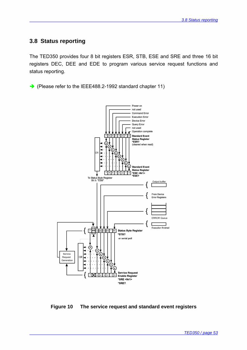
3.8 Status reporting
The TED350 provides four 8 bit registers ESR, STB, ESE and SRE and three 16 bit registers DEC, DEE and EDE to program various service request functions and status reporting.
(Please refer to the IEEE488.2-1992 standard chapter 11)
Figure 10 The service request and standard event registers
Output buffer
ERROR Queue
or serial poll
ServiceRequestGeneration
3.8 Status reporting
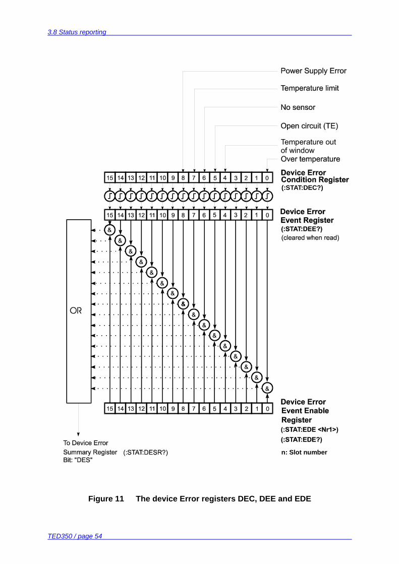
TED350 / page 54
Figure 11 The device Error registers DEC, DEE and EDE
(:STAT:DEC?)
n: Slot number
Temperature outof window
3.8 Status reporting
TED350 / page 55
3.8.1 Standard event status register (ESR)
The bits of this register mirror the following standard events: Power on This event bit indicates, that an off to on transition has
occurred in the power supply. So it is high after switching on the device for the first time.
User request (Not used) Command error A command error occurred. Execution error An execution error occurred. Device error A device dependent error occurred. Query error A query error occurred. Request control (Not used) Operation complete Can be set with "*OPC". The ESR can be read directly with the command "*ESR?". This read command clears the ESR. The content of the ESR can not be set. The bits are active high. 3.8.2 Standard event status enable register (ESE)
The bits of the ESE are used to select which bits of the ESR shall influence bit 5 (ESB) of the Status Byte Register (STB). The 8 bits of the ESE are connected by logical "AND" with the according 8 bits of the ESR. These 8 results are combined by logical "OR" so that any "hit" leads to a logical 1 in bit 5 (ESB) of the STB. As any bit of the STB can assert an SRQ every event (bit of the ESR) can be used to assert an SRQ.
3.8 Status reporting
TED350 / page 56
3.8.3 Status byte register (STB)
The bits of this register are showing the status of the TED350. RQS RQS: Request service message: Shows that this device
has asserted SRQ (red via serial poll). MSS Master summary status: Shows that this device requests a
service (read via "*STB?"). MAV (message available) This bit is high after a query request
as a result "waits" in the output queue to be fetched. It is low if the output queue is empty.
DES (device error status) This bit is high after a device error
occurred. Which device errors set this bit is defined with the EDE.
EAV (error available) This bit is high as long as there are errors
in the error queue. FIN (command finished) This bit is high, after a command has
finished and all bits of the STB have been set. The STB can be read directly with the command "*STB?". The content of the STB can not be set. The bits are active high. All bits except bit 6 of the STB can be used to assert a service request (SRQ) (Please refer to 3.8.5). Alternatively the SRQ can be recognized using the command "*STB?" (Please refer to 3.8.6) or by serial poll (Please refer to 3.8.7). 3.8.4 Service request enable register (SRE)
The bits of the SRE are used to select which bits of the STB shall assert an SRQ. Bit 0, 1, 2, 3, 4, 5 and 7 of the STB are combined by logical "AND" with the according 7 bits of the SRE. These 7 results are combined by logical "OR" so that any "hit" leads to a logical 1 in bit 6 of the STB and asserts an SRQ.
3.8 Status reporting
TED350 / page 57
3.8.5 Reading the STB by detecting SRQ
If an SRQ is asserted (see 3.8.4) bit 6 of the STB is set to logical 1 so that the controller can detect by auto serial polling which device asserted the SRQ. 3.8.6 Reading the STB by *STB? command
If the controller does not "listen" to SRQs at all the service request can be detected by reading the status byte with the command "*STB?". If bit 6 is logical 1 a service request was asserted. 3.8.7 Reading the STB by serial poll
If the controller does not support auto serial poll the service request can also be detected via manual serial poll. If bit 6 is logical 1 a service request was asserted.
3.8 Status reporting
TED350 / page 58
3.8.8 Device error condition register (DEC)
The bits of this register show the errors that occur during operation (operation errors). The bits are active high. If the error disappears the bits are reset to low. For an TED350 bits 0 and 4... 8 are used: (0) Over temperature Internal temperature too high. Wait until the TED350 has
cooled down. Maintain proper air flow. (4) Temperature window The TED350 asserted a temperature window protection
signal. (5) Open circuit The TED350 detected the TEC element to have a too high
resistance or being not present. (6) No sensor The TED350 detected no sensor connected to the output
jack. (7) Temperature limit The TED350 detected the temperature to reach the
temperature / resistance limit. (8) Power supply error Internal power supply error. The DEC can be read but not set. Reading does not clear the DEC.
3.8 Status reporting
TED350 / page 59
3.8.9 Device error event register (DEE)
The bits of this register hold the errors that occurred during operation (operation errors). So each bits of the DEC sets the according bit of the DEE. The DEE can be read but not set. Reading clears the DEE. 3.8.10 Device error event enable register (EDE)
The bits of the EDE are used to select which bits of the DEE shall influence bit 3 (DES) of the STB. The 8 bits of the EDE are related by logical "AND" to the according 8 bits of the DEE. These 8 results are combined by logical "OR" so that any "hit" leads to a logical 1 in bit 3 (DES) of the STB. As any bit of the STB can assert an SRQ every error (bit of the DEE) can be used to assert an SRQ.
3.9 Hints for setting up control programs
TED350 / page 60
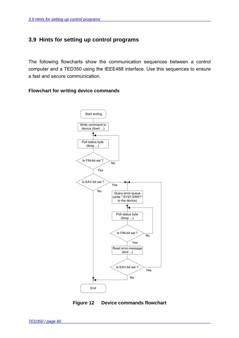
3.9 Hints for setting up control programs
The following flowcharts show the communication sequences between a control computer and a TED350 using the IEEE488 interface. Use this sequences to ensure a fast and secure communication. Flowchart for writing device commands
Figure 12 Device commands flowchart
Start writing
Write command to device (ibwrt ...)
Poll status byte (ibrsp ...)
Is FIN-bit set ?No
Yes
Yes
No
Is EAV-bit set ?
Is FIN-bit set ?No
Yes
Poll status byte (ibrsp ...)
Query error-queue (write “:SYST:ERR?“
to the device)
Read error-message(ibrd ...)
Yes
No
Is EAV-bit set ?
End
3.9 Hints for setting up control programs
TED350 / page 61
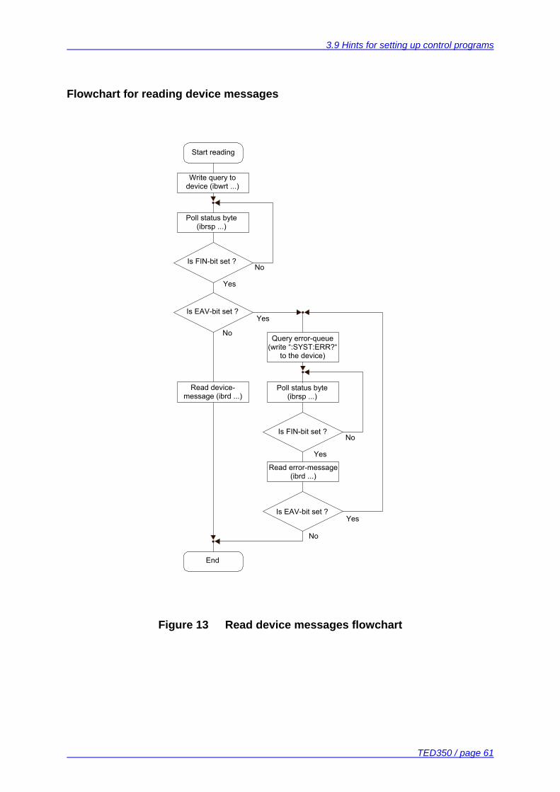
Flowchart for reading device messages
Figure 13 Read device messages flowchart
Start reading
Write query to device (ibwrt ...)
Poll status byte (ibrsp ...)
Is FIN-bit set ?No
Yes
Yes
No
Is EAV-bit set ?
Is FIN-bit set ?No
Yes
Poll status byte (ibrsp ...)
Query error-queue (write “:SYST:ERR?“
to the device)
Read error-message(ibrd ...)
Yes
No
Is EAV-bit set ?
End
Read device-message (ibrd ...)
3.9 Hints for setting up control programs
TED350 / page 62
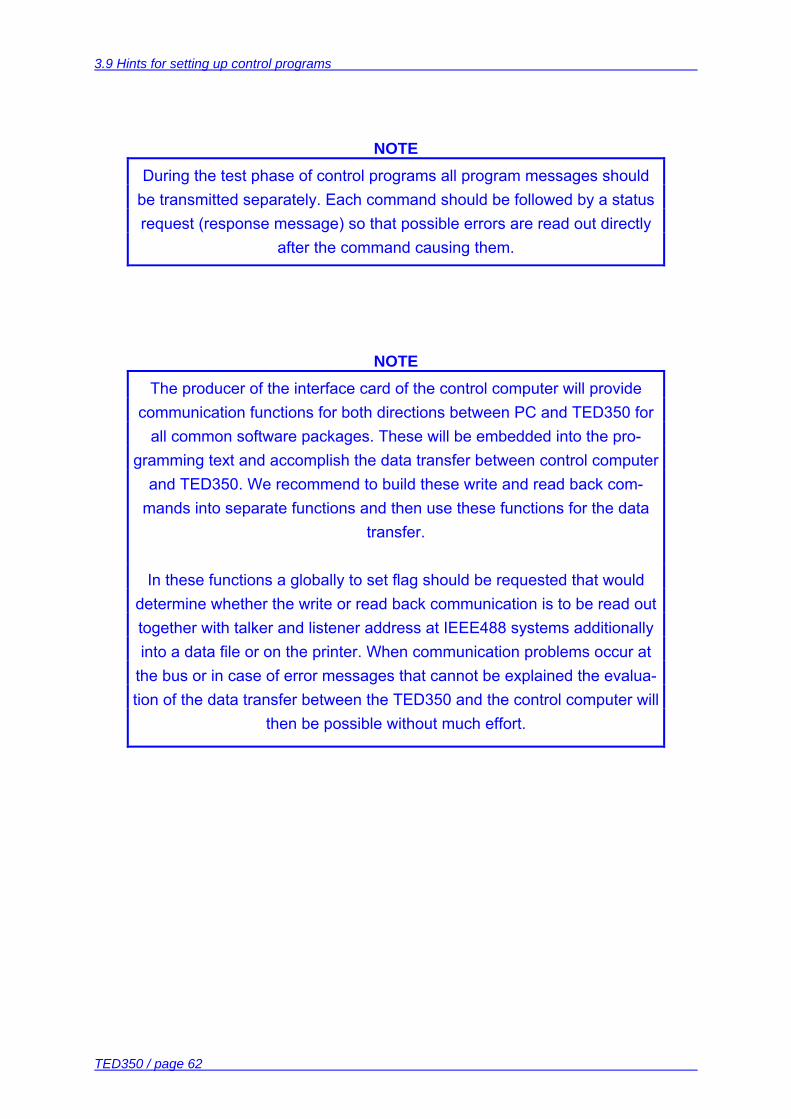
NOTE During the test phase of control programs all program messages should
be transmitted separately. Each command should be followed by a status request (response message) so that possible errors are read out directly
after the command causing them.
NOTE The producer of the interface card of the control computer will provide
communication functions for both directions between PC and TED350 for all common software packages. These will be embedded into the pro-
gramming text and accomplish the data transfer between control computer and TED350. We recommend to build these write and read back com-
mands into separate functions and then use these functions for the data transfer.
In these functions a globally to set flag should be requested that would determine whether the write or read back communication is to be read out together with talker and listener address at IEEE488 systems additionally into a data file or on the printer. When communication problems occur at
the bus or in case of error messages that cannot be explained the evalua-tion of the data transfer between the TED350 and the control computer will
then be possible without much effort.
4.1 General remarks
TED350 / page 63
4 Maintenance and Repair
4.1 General remarks
The TED350 does not need any regular maintenance by the user. To maintain the specifications for a long period of time we would recommend to have the unit re-calibrated by Thorlabs every second year. The TED350 does not possess any components to be repaired by the user. If any disturbances in function should occur please contact our Thorlabs technical hotline before sending the device to Thorlabs (Germany) for repair. 4.2 Cleaning
Inspect the instrument as often as operating conditions require. To clean the exterior surface, perform the following steps:
1. Remove loose dust on the outside of the instrument with a lint-free cloth. Use care to avoid scratching the clear plastic display filter.
2. Use a soft cloth dampened with water to clean the instrument. Use an aqueous solution of 75% isopropyl alcohol for more efficient cleaning.
Attention To avoid damage to the surface of the instrument, do not use any
abrasive or chemical cleaning agents.
4.3 Selecting the line voltage
TED350 / page 64
4.3 Selecting the line voltage
The line voltage can be selected with the line voltage selector on the rear of the TED350. The TED350 can be operated with 100V 115V and 230V (+15% , -10% each). Using a flat-blade screwdriver, turn the switch to the desired range by aligning the triangle with the appropriate voltage (100V, 115V, or 230V). Ensure that the switch has clicked into one of the three positions and is not between positions.
Attention When changing the line voltage, please do also change the mains
fuse to the appropriate value!
4.4 Exchanging the line fuse
If the line fuse has opened due to line disturbances, incorrectly set voltage or other influences from the outside it can be exchanged at the rear without opening the unit.
Attention To avoid fire hazard only the appropriate fuse for the corresponding
line voltage is to be used:
100V / 115V : T4H250V
230V : T2H250V Fuses: IEC 60127-2/V, 5 x 20 mm, 250V, Slow response
4.4 Exchanging the line fuse
TED350 / page 65
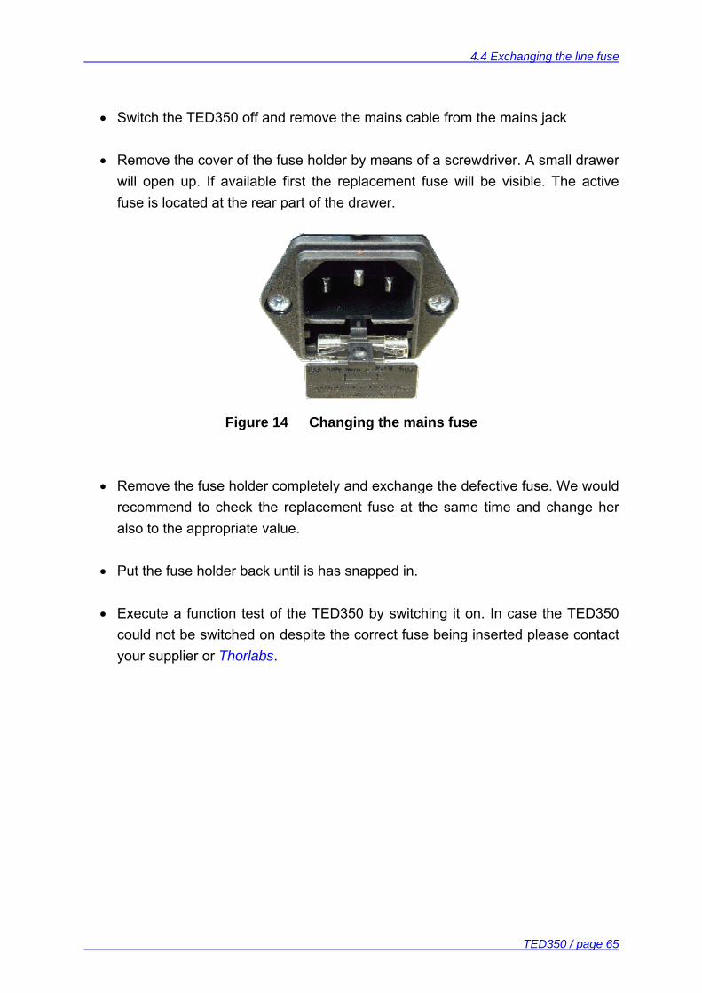
• Switch the TED350 off and remove the mains cable from the mains jack • Remove the cover of the fuse holder by means of a screwdriver. A small drawer
will open up. If available first the replacement fuse will be visible. The active fuse is located at the rear part of the drawer.
Figure 14 Changing the mains fuse
• Remove the fuse holder completely and exchange the defective fuse. We would
recommend to check the replacement fuse at the same time and change her also to the appropriate value.
• Put the fuse holder back until is has snapped in.
• Execute a function test of the TED350 by switching it on. In case the TED350
could not be switched on despite the correct fuse being inserted please contact your supplier or Thorlabs.
4.5 Troubleshooting
TED350 / page 66
4.5 Troubleshooting
In case that your TED350 system shows malfunction please check the following items:
Unit does not work at all (no display on the mainframe):
TED350 controller connected properly to the mains?
Connect the TED350 to the power line, pay attention to the right voltage
setting.
TED350 controller turned on?
Turn on the unit with the key mains-switch.
Control the fuse at the rear panel of the TED350.
If the fuse has opened, replace the fuse by the correct type
(refer to 4.4, “Exchanging the line fuse” on page 64)
You don’t get the desired operation temperature
Is the hardware limit ITEC LIM set to 0?
Adjust the hardware limit IMAX by means of the potentiometer on the
TED350 front panel to an appropriate value.
Is the TEC connected properly to the front connector?
Check all cables.
Check the correct polarity (see section 1.7.7.1, "Polarity check of the TEC
element" on page 17)
Are the PID-parameters set correctly?
Adjust the PID-parameters according to 2.1.6, "Setting the PID shares" on
page 21

4.5 Troubleshooting
TED350 / page 67
Is the temperature sensor connected properly and are his parameters entered
correctly?
Check the corresponding connections and polarities of the temperature
sensor (refer to chapters 1.7.2, to 1.7.6)
Select the corresponding temperature sensor manually or with the
":SENS: XY" command.
If you don’t find the error source by means of the trouble shooting list please first connect the Thorlabs-Hotline before sending the TED350 for checkup and repair to Thorlabs-Germany. (refer to section 6.7, “Addresses ” on page 76
5.1 Exchange of internal fuses
TED350 / page 68
5 Service
Attention Only qualified service personnel should perform service procedures.
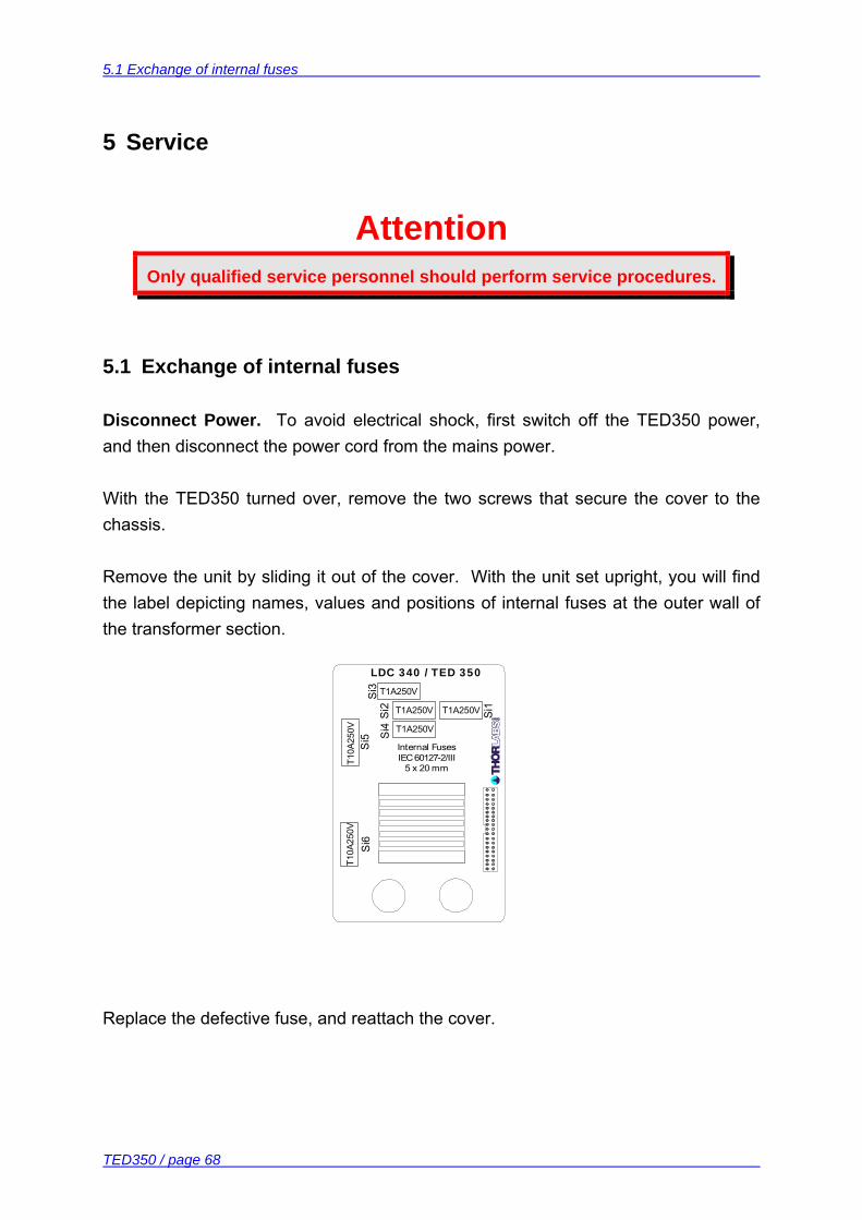
5.1 Exchange of internal fuses
Disconnect Power. To avoid electrical shock, first switch off the TED350 power, and then disconnect the power cord from the mains power. With the TED350 turned over, remove the two screws that secure the cover to the chassis. Remove the unit by sliding it out of the cover. With the unit set upright, you will find the label depicting names, values and positions of internal fuses at the outer wall of the transformer section.
Replace the defective fuse, and reattach the cover.
T10A
250V
LDC 340 / TED 350
Si3
Si5 S
i4
Internal Fuses IEC 60127-2/III
5 x 20 mm
Si6
Si2 Si1
T1A250V
T1A250V
T1A250V
T1A250V
T10A
250V
6.1 Warranty
TED350 / page 69
6 Appendix
6.1 Warranty
Thorlabs warrants material and production of the TED350 for a period of 24 months starting with the date of shipment. During this warranty period Thorlabs will see to defaults by repair or by exchange if these are entitled to warranty. For warranty repairs or service the unit must be sent back to Thorlabs (Germany) or to a place determined by Thorlabs. The customer will carry the shipping costs to Thorlabs, in case of warranty repairs Thorlabs will carry the shipping costs back to the customer. If no warranty repair is applicable the customer also has to carry the costs for back shipment. In case of shipment from outside EU duties, taxes etc. which should arise have to be carried by the customer. Thorlabs warrants the hard- and software determined by Thorlabs for this unit to operate fault-free provided that they are handled according to our requirements. However, Thorlabs does not warrant a fault free and uninterrupted operation of the unit, of the soft- or firmware for special applications nor this instruction manual to be error free. Thorlabs is not liable for consequential damages. Restriction of warranty The warranty mentioned before does not cover errors and defects being the result of improper treatment, software or interface not supplied by us, modification, misuse or operation outside the defined ambient stated by us or unauthorized maintenance. Further claims will not be consented to and will not be acknowledged. Thorlabs does explicitly not warrant the usability or the economical use for certain cases of application. Thorlabs reserves the right to change this instruction manual or the technical data of the described unit at any time.
0
TED350 / page 70
6.2 Certifications and compliances
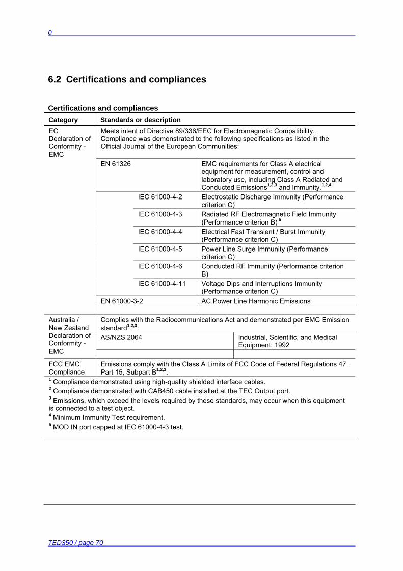
Certifications and compliances Category Standards or description EC Declaration of Conformity - EMC
Meets intent of Directive 89/336/EEC for Electromagnetic Compatibility. Compliance was demonstrated to the following specifications as listed in the Official Journal of the European Communities:
EN 61326 EMC requirements for Class A electrical equipment for measurement, control and laboratory use, including Class A Radiated and Conducted Emissions1,2,3 and Immunity.1,2,4
IEC 61000-4-2 Electrostatic Discharge Immunity (Performance criterion C)
IEC 61000-4-3 Radiated RF Electromagnetic Field Immunity (Performance criterion B) 5
IEC 61000-4-4 Electrical Fast Transient / Burst Immunity (Performance criterion C)
IEC 61000-4-5 Power Line Surge Immunity (Performance criterion C)
IEC 61000-4-6 Conducted RF Immunity (Performance criterion B)
IEC 61000-4-11 Voltage Dips and Interruptions Immunity (Performance criterion C)
EN 61000-3-2 AC Power Line Harmonic Emissions
Complies with the Radiocommunications Act and demonstrated per EMC Emission standard1,2,3: AS/NZS 2064 Industrial, Scientific, and Medical
Equipment: 1992
Australia / New Zealand Declaration of Conformity - EMC FCC EMC Compliance
Emissions comply with the Class A Limits of FCC Code of Federal Regulations 47, Part 15, Subpart B1,2,3.
1 Compliance demonstrated using high-quality shielded interface cables. 2 Compliance demonstrated with CAB450 cable installed at the TEC Output port. 3 Emissions, which exceed the levels required by these standards, may occur when this equipment is connected to a test object. 4 Minimum Immunity Test requirement. 5 MOD IN port capped at IEC 61000-4-3 test.
6.3 Thorlabs “End of Life” policy (WEEE)
TED350 / page 71
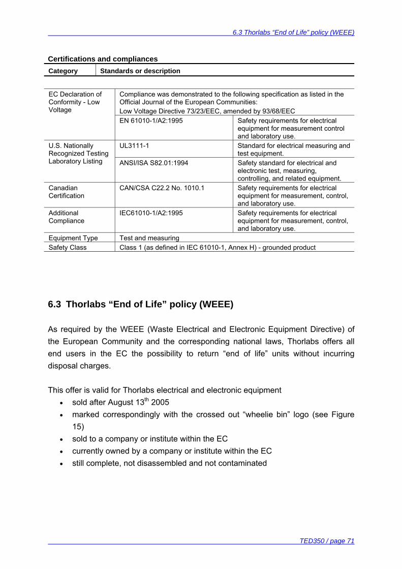
Certifications and compliances Category Standards or description
EC Declaration of Conformity - Low Voltage
Compliance was demonstrated to the following specification as listed in the Official Journal of the European Communities: Low Voltage Directive 73/23/EEC, amended by 93/68/EEC
EN 61010-1/A2:1995 Safety requirements for electrical equipment for measurement control and laboratory use.
UL3111-1 Standard for electrical measuring and test equipment.
U.S. Nationally Recognized Testing Laboratory Listing ANSI/ISA S82.01:1994 Safety standard for electrical and
electronic test, measuring, controlling, and related equipment.
Canadian Certification
CAN/CSA C22.2 No. 1010.1 Safety requirements for electrical equipment for measurement, control, and laboratory use.
Additional Compliance
IEC61010-1/A2:1995 Safety requirements for electrical equipment for measurement, control, and laboratory use.
Equipment Type Test and measuring Safety Class Class 1 (as defined in IEC 61010-1, Annex H) - grounded product
6.3 Thorlabs “End of Life” policy (WEEE)
As required by the WEEE (Waste Electrical and Electronic Equipment Directive) of the European Community and the corresponding national laws, Thorlabs offers all end users in the EC the possibility to return “end of life” units without incurring disposal charges. This offer is valid for Thorlabs electrical and electronic equipment
• sold after August 13th 2005 • marked correspondingly with the crossed out “wheelie bin” logo (see Figure
15) • sold to a company or institute within the EC • currently owned by a company or institute within the EC • still complete, not disassembled and not contaminated
6.3 Thorlabs “End of Life” policy (WEEE)
TED350 / page 72
As the WEEE directive applies to self contained operational electrical and electronic products, this “end of life” take back service does not refer to other Thorlabs products, such as
• pure OEM products, that means assemblies to be built into a unit by the user (e. g. OEM laser driver cards)
• components • mechanics and optics • left over parts of units disassembled by the user (PCB’s, housings etc.).
If you wish to return a Thorlabs unit for waste recovery, please contact Thorlabs or your nearest dealer for further information. 6.3.1 Waste treatment on your own responsibility
If you do not return an “end of life” unit to Thorlabs, you must hand it to a company specialized in waste recovery. Do not dispose of the unit in a litter bin or at a public waste disposal site. 6.3.2 Ecological background
It is well known that WEEE pollutes the environment by releasing toxic products during decomposition. The aim of the European RoHS directive is to reduce the content of toxic substances in electronic products in the future. The intent of the WEEE directive is to enforce the recycling of WEEE. A controlled recycling of end of live products will thereby avoid negative impacts on the environment.
6.3 Thorlabs “End of Life” policy (WEEE)
TED350 / page 73
Figure 15 Crossed out “wheelie bin” symbol
6.4 List of acronyms
TED350 / page 74
6.4 List of acronyms
AC Alternating Current ADC Analog to Digital Converter ASCII American Standard Code for Information Interchange CC Constant Current CLR CleaR CR Carriage Return CRD Character Response Data DAC Digital to Analog Converter D-Share Differential share DC Direct Current DCL Device Clear DEC Device Error Condition Register DEE Device Error Event Register DES Device Error Status DIN Deutsche Industrie Norm DIP Dual In-line Package DUT Device Under Test EAV Error AVailable EDE Enable Device Error Event Register EOI End Of Information ERR ERRor ESE Standard Event Status Enable register ESR Event Status Register FIN Command FINished GET Group Execute Trigger GTL Go To Local IEEE Institute for Electrical and Electronic Engineering I-Share Integral share LED Light Emitting Diode LF Line Feed LLO Local Lockout NR1 Numeric Response data of type 1 NR2 Numeric Response data of type 2 NR3 Numeric Response data of type 3 MAV Message AVailable) MSS Master Summary Status
6.5 List of figures
TED350 / page 75
OTP Over TemPerature PC Personal Computer PID Proportional, Integral, Differential (regulator) P-Share Proportional share RF Radio Frequency RMS Root Mean Squared RQS ReQuest Service Message SDC Selected Device Clear SRE Service Request Enable Register SRQ Service ReQuest STB STatus Byte Register TEC ThermoElectric Cooler (Peltier Element) 6.5 List of figures
Figure 1 Operating elements on front panel 8 Figure 2 Operating elements on rear panel 9 Figure 3 Pinning of the output jack 11 Figure 4 Connecting a thermistor 12 Figure 5 Connecting an AD590 or AD592 13 Figure 6 Connecting a LM135 or LM335 14 Figure 7 Connecting an LM35 14 Figure 8 Connecting the Pt-100 (option) 15 Figure 9 Connecting the TEC element 16 Figure 10 The service request and standard event registers 53 Figure 11 The device Error registers DEC, DEE and EDE 54 Figure 12 Device commands flowchart 60 Figure 13 Read device messages flowchart 61 Figure 14 Changing the mains fuse 65 Figure 15 Crossed out “wheelie bin” symbol 73

6.6 List of tables
TED350 / page 76
6.6 List of tables
Table 1 IEEE 488 Interface subsets 29 Table 2 IEEE 488 address setting 31 Table 3 Oversampling rate 41 6.7 Addresses
Our Company is represented by several distributors and sales offices throughout the world. Europe Thorlabs GmbH Hans-Boeckler-Str. 6 D-85221 Dachau / Munich Germany Sales and Support Phone: +49 (0) 81 31 / 5956-0 Fax: +49 (0) 81 31 / 5956-99 Email: [email protected] Web: www.thorlabs.com USA Thorlabs, Inc. 435 Route 206 North Newton, NJ 07860 USA Sales and Support Phone: 1-973-579-7227 Fax: 1-973-300-3600 Email: [email protected] Email: [email protected] Web: www.thorlabs.com

6.7 Addresses
TED350 / page 77
Japan Thorlabs, Inc. 6th Floor, Fujimizaka Building 5-17-1, Ohtsuka Bunkyo-ku, Tokyo 112-0012 Japan Sales and Support Phone: +81-3-5977-8401 Fax: +81-3-5977-8402 Email: [email protected] Web: www.thorlabs.jp Please call our hotlines, send an Email to ask for your nearest distributor or just visit our homepage http://www.thorlabs.com