Embed Size (px)
Citation preview

Twido Extreme Programmable Controller
35013462 06/2011
3501
3462
.05
www.schneider-electric.com
Twido Extreme Programmable ControllerHardware Guide
06/2011

The information provided in this documentation contains general descriptions and/or technical characteristics of the performance of the products contained herein. This documentation is not intended as a substitute for and is not to be used for determining suitability or reliability of these products for specific user applications. It is the duty of any such user or integrator to perform the appropriate and complete risk analysis, evaluation and testing of the products with respect to the relevant specific application or use thereof. Neither Schneider Electric nor any of its affiliates or subsidiaries shall be responsible or liable for misuse of the information contained herein. If you have any suggestions for improvements or amendments or have found errors in this publication, please notify us.
The information provided in this documentation contains general descriptions and/or technical characteristics of the performance of the products contained herein. This documentation is not intended as a substitute for and is not to be used for determining suitability or reliability of these products for specific user applications. It is the duty of any such user or integrator to perform the appropriate and complete risk analysis, evaluation and testing of the products with respect to the relevant specific application or use thereof. Neither Schneider Electric nor any of its affiliates or subsidiaries shall be responsible or liable for misuse of the information contained herein. If you have any suggestions for improvements or amendments or have found errors in this publication, please notify us.
The information provided in this documentation contains general descriptions and/or technical characteristics of the performance of the products contained herein. This documentation is not intended as a substitute for and is not to be used for determining suitability or reliability of these products for specific user applications. It is the duty of any such user or integrator to perform the appropriate and complete risk analysis, evaluation and testing of the products with respect to the relevant specific application or use thereof. Neither Schneider Electric nor any of its affiliates or subsidiaries shall be responsible or liable for misuse of the information contained herein. If you have any suggestions for improvements or amendments or have found errors in this publication, please notify us.
The information provided in this documentation contains general descriptions and/or technical characteristics of the performance of the products contained herein. This documentation is not intended as a substitute for and is not to be used for determining suitability or reliability of these products for specific user applications. It is the duty of any such user or integrator to perform the appropriate and complete risk analysis, evaluation and testing of the products with respect to the relevant specific application or use thereof. Neither Schneider Electric nor any of its affiliates or subsidiaries shall be responsible or liable for misuse of the information contained herein. If you have any suggestions for improvements or amendments or have found errors in this publication, please notify us.
2 35013462 06/2011

The information provided in this documentation contains general descriptions and/or technical characteristics of the performance of the products contained herein. This documentation is not intended as a substitute for and is not to be used for determining suitability or reliability of these products for specific user applications. It is the duty of any such user or integrator to perform the appropriate and complete risk analysis, evaluation and testing of the products with respect to the relevant specific application or use thereof. Neither Schneider Electric nor any of its affiliates or subsidiaries shall be responsible or liable for misuse of the information contained herein. If you have any suggestions for improvements or amendments or have found errors in this publication, please notify us.
The information provided in this documentation contains general descriptions and/or technical characteristics of the performance of the products contained herein. This documentation is not intended as a substitute for and is not to be used for determining suitability or reliability of these products for specific user applications. It is the duty of any such user or integrator to perform the appropriate and complete risk analysis, evaluation and testing of the products with respect to the relevant specific application or use thereof. Neither Schneider Electric nor any of its affiliates or subsidiaries shall be responsible or liable for misuse of the information contained herein. If you have any suggestions for improvements or amendments or have found errors in this publication, please notify us.
© 2011 Schneider Electric. All rights reserved.
35013462 06/2011 3

4 35013462 06/2011

Table of Contents
Safety Information . . . . . . . . . . . . . . . . . . . . . . . . . . . . . . 7About the Book . . . . . . . . . . . . . . . . . . . . . . . . . . . . . . . . . 9
Chapter 1 Twido Extreme Overview . . . . . . . . . . . . . . . . . . . . . . . . . 11Twido Extreme Controller Description. . . . . . . . . . . . . . . . . . . . . . . . . . . . 12Controller Features . . . . . . . . . . . . . . . . . . . . . . . . . . . . . . . . . . . . . . . . . . 14Options . . . . . . . . . . . . . . . . . . . . . . . . . . . . . . . . . . . . . . . . . . . . . . . . . . . 16Accessories . . . . . . . . . . . . . . . . . . . . . . . . . . . . . . . . . . . . . . . . . . . . . . . . 19Communication Overview . . . . . . . . . . . . . . . . . . . . . . . . . . . . . . . . . . . . . 22CANopen Communication. . . . . . . . . . . . . . . . . . . . . . . . . . . . . . . . . . . . . 24CANJ1939 Communication . . . . . . . . . . . . . . . . . . . . . . . . . . . . . . . . . . . . 26Modbus RTU and ASCII Communication . . . . . . . . . . . . . . . . . . . . . . . . . 28
Chapter 2 Installation. . . . . . . . . . . . . . . . . . . . . . . . . . . . . . . . . . . . . 33Power Supply Requirements. . . . . . . . . . . . . . . . . . . . . . . . . . . . . . . . . . . 34Twido Extreme Controller Dimensions . . . . . . . . . . . . . . . . . . . . . . . . . . . 36Environment Characteristics . . . . . . . . . . . . . . . . . . . . . . . . . . . . . . . . . . . 37Mounting Instructions . . . . . . . . . . . . . . . . . . . . . . . . . . . . . . . . . . . . . . . . 38
Chapter 3 Wiring Rules and Recommendations . . . . . . . . . . . . . . . 453.1 Wiring Overview . . . . . . . . . . . . . . . . . . . . . . . . . . . . . . . . . . . . . . . . . . . . 46
Wiring Rules and Recommendations . . . . . . . . . . . . . . . . . . . . . . . . . . . . 47Contacts Location on the Connector . . . . . . . . . . . . . . . . . . . . . . . . . . . . . 50Inputs and Outputs List Sorted by Type . . . . . . . . . . . . . . . . . . . . . . . . . . 52Inputs and Outputs List Sorted by Number . . . . . . . . . . . . . . . . . . . . . . . . 55RS485 Modbus Connection . . . . . . . . . . . . . . . . . . . . . . . . . . . . . . . . . . . 58Network Wiring . . . . . . . . . . . . . . . . . . . . . . . . . . . . . . . . . . . . . . . . . . . . . 59Inputs and Outputs Special Functions. . . . . . . . . . . . . . . . . . . . . . . . . . . . 62
3.2 Inputs Description . . . . . . . . . . . . . . . . . . . . . . . . . . . . . . . . . . . . . . . . . . . 65Introduction to Inputs. . . . . . . . . . . . . . . . . . . . . . . . . . . . . . . . . . . . . . . . . 66Key Switch Input . . . . . . . . . . . . . . . . . . . . . . . . . . . . . . . . . . . . . . . . . . . . 68Switch to Ground Inputs . . . . . . . . . . . . . . . . . . . . . . . . . . . . . . . . . . . . . . 70Switch to Battery Inputs. . . . . . . . . . . . . . . . . . . . . . . . . . . . . . . . . . . . . . . 72
35013462 06/2011 5

Active Analog Sensor Inputs . . . . . . . . . . . . . . . . . . . . . . . . . . . . . . . . . . 74Passive Analog Sensor Inputs. . . . . . . . . . . . . . . . . . . . . . . . . . . . . . . . . 76Analog or PWM Input. . . . . . . . . . . . . . . . . . . . . . . . . . . . . . . . . . . . . . . . 78PWM Input . . . . . . . . . . . . . . . . . . . . . . . . . . . . . . . . . . . . . . . . . . . . . . . . 81
3.3 Outputs Description . . . . . . . . . . . . . . . . . . . . . . . . . . . . . . . . . . . . . . . . . 83Introduction to Outputs . . . . . . . . . . . . . . . . . . . . . . . . . . . . . . . . . . . . . . 841 A Discrete Output . . . . . . . . . . . . . . . . . . . . . . . . . . . . . . . . . . . . . . . . . 8550 mA Discrete Output. . . . . . . . . . . . . . . . . . . . . . . . . . . . . . . . . . . . . . . 87300 mA Discrete Outputs. . . . . . . . . . . . . . . . . . . . . . . . . . . . . . . . . . . . . 89PWM/PLS Outputs. . . . . . . . . . . . . . . . . . . . . . . . . . . . . . . . . . . . . . . . . . 92
Chapter 4 Controller Operation . . . . . . . . . . . . . . . . . . . . . . . . . . . . . 95Cyclic Scan . . . . . . . . . . . . . . . . . . . . . . . . . . . . . . . . . . . . . . . . . . . . . . . 96Periodic Scan. . . . . . . . . . . . . . . . . . . . . . . . . . . . . . . . . . . . . . . . . . . . . . 98Checking Scan Time . . . . . . . . . . . . . . . . . . . . . . . . . . . . . . . . . . . . . . . . 101Operating Modes . . . . . . . . . . . . . . . . . . . . . . . . . . . . . . . . . . . . . . . . . . . 102Dealing with Power Cuts and Power Restoration . . . . . . . . . . . . . . . . . . 104Dealing with a Warm Restart . . . . . . . . . . . . . . . . . . . . . . . . . . . . . . . . . . 106Dealing with a Cold Start . . . . . . . . . . . . . . . . . . . . . . . . . . . . . . . . . . . . . 108Initialization of objects . . . . . . . . . . . . . . . . . . . . . . . . . . . . . . . . . . . . . . . 110
Appendices . . . . . . . . . . . . . . . . . . . . . . . . . . . . . . . . . . . . . . . . . . . 113Appendix A Appendices. . . . . . . . . . . . . . . . . . . . . . . . . . . . . . . . . . . . . 115
Application Example for Mobile Vehicles. . . . . . . . . . . . . . . . . . . . . . . . . 116Single Axis Lever . . . . . . . . . . . . . . . . . . . . . . . . . . . . . . . . . . . . . . . . . . . 118Glossary of Symbols . . . . . . . . . . . . . . . . . . . . . . . . . . . . . . . . . . . . . . . . 123Agency Requirements . . . . . . . . . . . . . . . . . . . . . . . . . . . . . . . . . . . . . . . 124
Glossary . . . . . . . . . . . . . . . . . . . . . . . . . . . . . . . . . . . . . . . . . . . 125Index . . . . . . . . . . . . . . . . . . . . . . . . . . . . . . . . . . . . . . . . . . . 131
6 35013462 06/2011
§
Safety InformationImportant Information
NOTICERead these instructions carefully, and look at the equipment to become familiar with the device before trying to install, operate, or maintain it. The following special messages may appear throughout this documentation or on the equipment to warn of potential hazards or to call attention to information that clarifies or simplifies a procedure.
35013462 06/2011 7

PLEASE NOTEElectrical equipment should be installed, operated, serviced, and maintained only by qualified personnel. No responsibility is assumed by Schneider Electric for any consequences arising out of the use of this material.
A qualified person is one who has skills and knowledge related to the construction and operation of electrical equipment and its installation, and has received safety training to recognize and avoid the hazards involved.
8 35013462 06/2011

About the Book
At a Glance
Document ScopeThis manual describes the hardware for a Twido Extreme programmable controller base.
It provides a description of the different parts, explains mounting operations and gives wiring instructions.
Validity NoteThe information in this manual applies only to a Twido Extreme programmable controller base. This documentation is valid for TwidoSuite Version 2.3
User CommentsWe welcome your comments about this document. You can reach us by e-mail at [email protected].
35013462 06/2011 9

10 35013462 06/2011
35013462 06/2011
1
Twido Extreme Programmable Controller Twido Extreme Overview35013462 06/2011
Twido Extreme Overview
IntroductionThis chapter gives an overview of Twido Extreme: it describes its configurations, its functions and the communication system.
What’s in this Chapter?This chapter contains the following topics:
Topic Page
Twido Extreme Controller Description 12
Controller Features 14
Options 16
Accessories 19
Communication Overview 22
CANopen Communication 24
CANJ1939 Communication 26
Modbus RTU and ASCII Communication 28
11

Twido Extreme Overview
Twido Extreme Controller Description
IntroductionThe Twido Extreme controller can be powered by an external battery with voltage:
either 12 VDC (%Q0.10 to %Q017 are available when nominal voltage ranges from 9 to 16 VDC),or 24 VDC (nominal voltage ranging from 18 to 32 VDC).
NOTE: The length of the power supply cable must not exceed 30 m (98.4 ft).
Low voltage electrical installations, Fundamental principles : IEC60364 series
The shield terminals (CANopen shield (40), CANJ1939 shield (51)) are not directly connected to the chassis.
For the installer claimant an equipotentiality shield-chassis, add connection shield-chassis upstream of the controller.
The Twido Extreme has the ability to locally control machinery in its own severe environment and to use communication bus for more distant components.
For application in machinery, use EN/IEC 60204-1 (Safety of machinery - Electrical equipement of machines - General requirements),UL 508, CSA C22.2 N°142.
The Twido Extreme is well suitable for automotive application.
Twido Extreme Controller Model
For more information on the accessories and options available, see Options, page 16 and Accessories, page 19.
Model Reference Illustration
TWD LEDC K1 The nominal battery power supply voltage is either 12 VDC or 24 VDC.Both systems handle 22 inputs and 19 outputs.Note: Twido Extreme has no internal battery.
Twido Extreme is protected for 1 hour against reverse voltage.
12 35013462 06/2011

Twido Extreme Overview
Battery Twido Extreme has no internal battery. A specific input, the key switch input, is used to turn the controller ON and OFF and to put it in standby mode.
Twido Extreme must continuously be connected to the battery (Steady State Voltage) to avoid loss of SRAM memory and operate properly.
For more information on this feature, see Key Switch Input, page 68.
Input/Output Extensions The number of inputs and outputs can be extended through the CANopen communication bus.
To carry out an extension, use IP67 distributed I/O interfaces such as Advantys FTB or FTM splitter boxes. They allow distributed connection of sensors and actuators on machines through CANopen.
For more information on Advantys FTB or FTM splitter boxes, see the guides available on Schneider Electric website (http://www.schneider-electric.com).
Communication CapabilitiesThe Twido Extreme Controller communication capabilities are based on the 3 following communication ports.
Serial line RS485 CANopen portCANJ1939 port
Associated SoftwareTo perform operations on Twido Extreme, you can use the following software tools:
TwidoSuiteTwidoSuite 1.20 or later is used to create, configure, operate and maintain applications for Twido programmable controllers with a PC.TwidoAdjustTwidoAdjust 3.0 is used to manage and monitor a Twido application with a Pocket PC.
For more information on these tools, see the guides available on Schneider Electric website (http://www.schneider-electric.com).
35013462 06/2011 13

Twido Extreme Overview
Controller Features
IntroductionBy default, all I/Os on the base are configured as discrete I/Os. However, dedicated I/Os can be assigned to specific functions during configuration such as:
RUN/STOP input
Latching inputs
Fast counter: single up/down counter 10 kHz
Controller status output
Pulse Width Modulation (PWM)
Pulse (PLS) generator output
Twido Extreme controllers are programmed using TwidoSuite which enables the following functions to be used:
PWMPLSFast counter
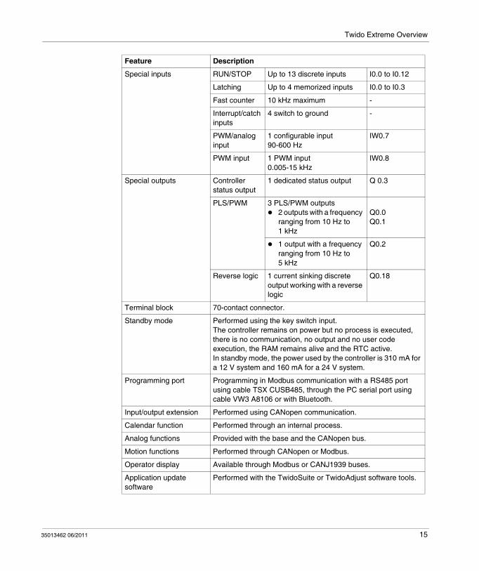
Main FeaturesThe following table lists the main features of the base:
Feature Description
Scanning Normal (cyclical) or periodic (constant) (2 ms to 150 ms).
Execution time 0.14 μs to 0.9 μs for a list instruction.
Memory capacity Data: 3000 memory words.Program: 22 inputs and 19 outputs, 3000 instruction lists.
Modbus communication Non-isolated EIA RS-485 type, maximum length limited to 30.5 m (100 ft).ASCII or RTU mode.
ASCII communication Half-duplex protocol to a device.
Dedicated functions 1 fast counter3 PLS/PWM outputs 1 PWM/analog input 1 PWM input
Programmable input filter Input filter time can be changed by configuration.Filtering at 3 m by default, no filtering or 12 ms by configuration.
14 35013462 06/2011
Twido Extreme Overview
Special inputs RUN/STOP Up to 13 discrete inputs I0.0 to I0.12
Latching Up to 4 memorized inputs I0.0 to I0.3
Fast counter 10 kHz maximum -
Interrupt/catch inputs
4 switch to ground -
PWM/analog input
1 configurable input 90-600 Hz
IW0.7
PWM input 1 PWM input 0.005-15 kHz
IW0.8
Special outputs Controller status output
1 dedicated status output Q 0.3
PLS/PWM 3 PLS/PWM outputs2 outputs with a frequency ranging from 10 Hz to 1 kHz
Q0.0Q0.1
1 output with a frequency ranging from 10 Hz to 5 kHz
Q0.2
Reverse logic 1 current sinking discrete output working with a reverse logic
Q0.18
Terminal block 70-contact connector.
Standby mode Performed using the key switch input.The controller remains on power but no process is executed, there is no communication, no output and no user code execution, the RAM remains alive and the RTC active.In standby mode, the power used by the controller is 310 mA for a 12 V system and 160 mA for a 24 V system.
Programming port Programming in Modbus communication with a RS485 port using cable TSX CUSB485, through the PC serial port using cable VW3 A8106 or with Bluetooth.
Input/output extension Performed using CANopen communication.
Calendar function Performed through an internal process.
Analog functions Provided with the base and the CANopen bus.
Motion functions Performed through CANopen or Modbus.
Operator display Available through Modbus or CANJ1939 buses.
Application update software
Performed with the TwidoSuite or TwidoAdjust software tools.
Feature Description
35013462 06/2011 15

Twido Extreme Overview
Options
IntroductionThis section describes the options compatible with Twido Extreme that can be combined to set up an application.
An example of application set up for mobile vehicles is described in the appendices.
SensorsThe following sensors are compatible with Twido Extreme.
NOTE: Sensors are connected by means of standard M12 connectors for Advantys FTB and M12/M8 connectors for Advantys FTM.
Actuators and RelaysActuators must comply with the following discrete outputs of the controller:
1 A: 1 output 50 mA: 1 output 300 mA: 14 outputs (8 have a 150 V protection limit and 6 have a 85 V protection limit)
NOTE: Actuators are connected by means of standard M12 connectors for Advantys FTB and M12/M8 connectors for Advantys FTM.
To command high power actuators, use:
Static relays on the PWM output for precise control.For example, a PWM output can be used with hydraulic valves that require up to 3 A. Normal relays as indicated in the table below:
Characteristic Description
Sensor type Twido Extreme allows the connection of standard ON/OFF sensors.
Voltage requirements 5 V or 8 V analog sensors are to be used.
Specific input Twido Extreme PWM (Pulse With Modulation) input is used to connect devices in extremely harsh environments that require proportional information, such as a single axis lever or a joystick.
Specific output Twido Extreme PWM (Pulse With Modulation) output is used to connect devices in extremely harsh environments that require proportional information, such as hydraulic valves.
Reference Relays
RPF2ABD Power relay 2 NO/24 VDC
16 35013462 06/2011

Twido Extreme Overview
Cables and Adapters The following table lists the optional cables.
NOTE: For more details on RJ45 plug and Twido Extreme contacts connection see RS485 Modbus Plug Connection, page 58
RPF2AJD Power relay 2 NO/12 VDC
RPF2BBD Power relay 2 CO/24 VDC
RPF2BJD Power relay 2 CO/12 VDC
Reference Relays
Reference Cables
TWD XCAFJ010 RS485 connection cable equipped with a RJ45 plug and wires at the other end.
FTX CN32.. CANopen bus cables equipped with a M12 plug, the following lengths are available:
FTX CN3203 for 0.3 m (0.98 ft)FTX CN3206 for 0.6 m (1.97 ft)FTX CN3210 for 1 m (3.28 ft)FTX CN3220 for 2 m (6.56 ft)FTX CN3230 for 3 m (9.84 ft)FTX CN3250 for 5 m (16.4 ft)
TSX CANCA.. CANopen and CANJ1939 network cable, the following lengths are available:
TSX CANCA50 for 50 m (164 ft)TSX CANCA100 for 100 m (328 ft)TSX CANCA300 for 300 m (984 ft)
VW3 A8106 PC to controller programming cable for RS485-RS232 conversionCable equipped with SUB-D 9 and RJ45 at the other end, 2 m (6.56 ft)
TSX CUSB485 PC to controller programming cable powered by the PC through a USB plugNote: Position the rotary switch on 0 (TER - MULTI function).
VW3 A8114 PC to controller Bluetooth Modbus adapter
VW3 A8115 PC Bluetooth USB key
35013462 06/2011 17

Twido Extreme Overview
Display Interfaces Two types of interfaces can be connected to Twido Extreme.
A control and operations dialog display This display communicates with Twido Extreme using the Modbus protocol on a serial link RS485. It can be any type of XBT supporting a Modbus protocol, a XBT N or a XBT GT display for example.
A cameraA camera can be connected to a XBT GT display.
18 35013462 06/2011

Twido Extreme Overview
Accessories
IntroductionThis section describes the Twido Extreme controller accessories and their characteristics.
Twido Extreme can be associated:
with connector kit (reference TWD FCN K70) that you must assemble,with an already mounted IP67 connector (reference TWD FCWK70L015) equipped with a 1.5 m (4.92 ft) long cable.
Connector Kit
Reference Description
TWD FCN K70 The connector kit includes the following parts:A 70-contact connector
80 sockets to crimp the wires to the connector
80 stoppers
A protection end bell
35013462 06/2011 19
Twido Extreme Overview
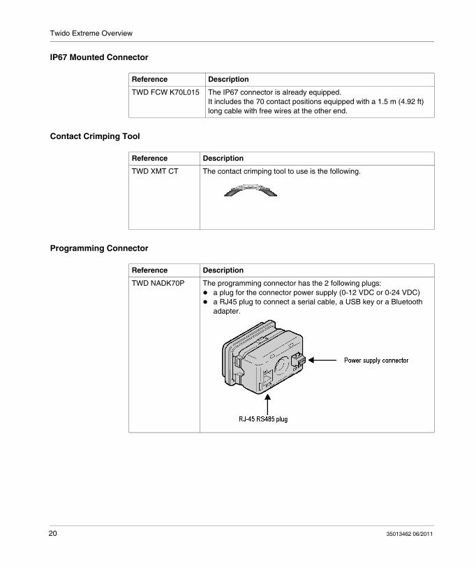
IP67 Mounted Connector
Contact Crimping Tool
Programming Connector
Reference Description
TWD FCW K70L015 The IP67 connector is already equipped. It includes the 70 contact positions equipped with a 1.5 m (4.92 ft) long cable with free wires at the other end.
Reference Description
TWD XMT CT The contact crimping tool to use is the following.
Reference Description
TWD NADK70P The programming connector has the 2 following plugs:a plug for the connector power supply (0-12 VDC or 0-24 VDC)a RJ45 plug to connect a serial cable, a USB key or a Bluetooth adapter.
20 35013462 06/2011

Twido Extreme Overview
Bluetooth Dongle
Mounting Kit The mounting kit provides compatible mounting parts to mount the controller.
Reference Description
VW3 A8114 The Bluetooth dongle provides wireless connection for the programming phase. This dongle manages D0 and D1 signal (Tx Rx), the ground and the 5 VDC power supply (D0 signal is connected to contact 5 and D1 signal is connected to contact 4).
VW3 A8115 The Bluetooth USB key is used for PC not equipped with Bluetooth.
Reference Description
TWD XMT K4 The mounting kit includes parts for 4 holes:8 shock mounts8 washers4 spacers
4 8 mm (0.31 in) bolts are required for the mounting kit.
35013462 06/2011 21

Twido Extreme Overview
Communication Overview
IntroductionTwido Extreme has one serial port used for application management and data animation.
5 types of communications can be used with a Twido Extreme system:
CANopen fieldbus connectionCANJ1939 fieldbus connectionEthernet Network connection, possible through the Modbus Ethernet box OSITRACK XGS Z33ETH Modem connectionBluetooth connection
The communication services provide data distribution functions for exchanging data with I/O devices and messaging functions for communicating to external devices.
The application management services manage and configure the base through TwidoSuite software.
To provide these services, 2 protocols are available:
Modbus Note that Ethernet communications implement the Modbus TCP/IP protocol.
ASCII
22 35013462 06/2011

Twido Extreme Overview
Communication Architecture The following illustration gives an overview of the typical architecture including the 3 protocols.
NOTE: The different buses must be configured with the TwidoSuite software.
35013462 06/2011 23

Twido Extreme Overview
CANopen Communication
IntroductionThis section describes the CANopen communication.
CANopen CapabilitiesThe Twido Extreme Controller can be connected to a CANopen fieldbus.
The CANopen fieldbus functions in master mode only, with the following characteristics:
16 PDOs in emission16 PDOs in reception100 SDOs125 kbits/s, 250 kbits/s and 500 kbits/s transmission speedNo synchronization modeHeartbeat and node guarding supervision mode
On the CANopen bus, the syntax used for exchanged data is as follows:
IWCx,y,z, QWCx,y,z
where:
x represents the channel number,x=1 for the CANopen busx=0 for the CAN J1939 bus.
y represents the object number from the object list,z represents the sub-object number.
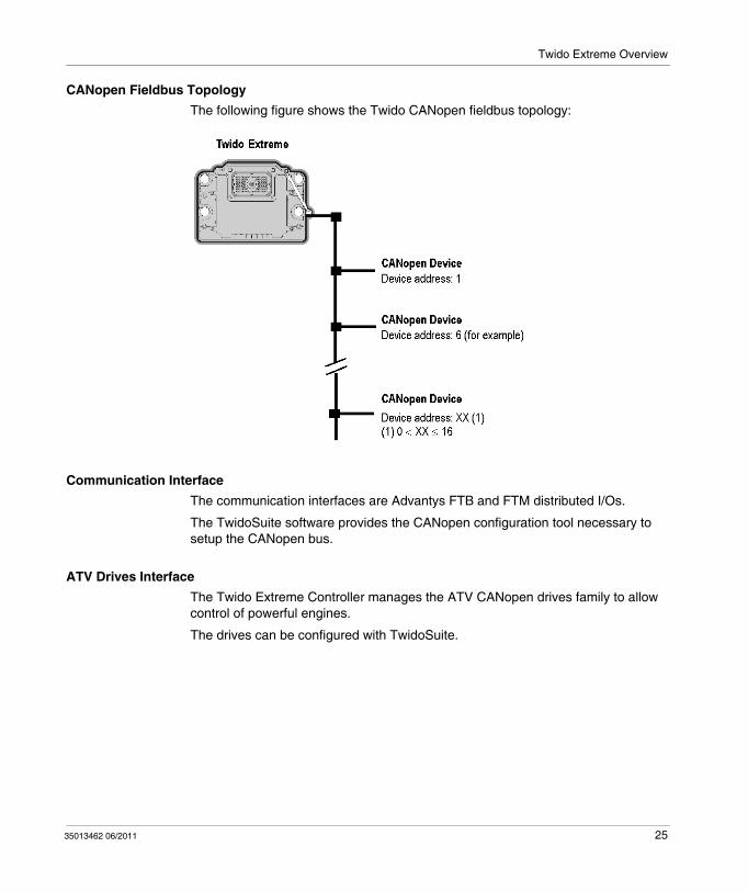
CANopen Fieldbus DescriptionThe CANopen architecture of a Twido Extreme system consists of:
Twido Extreme controller as master port,Up to 16 CANopen PDOs exchanged on the bus, with addresses ranging from 1 to 16.
NOTE: The baud rate of the bus depends on its length and on the cable type used. See "Cable Length and Transmission Speed" in the Communication Guide.
24 35013462 06/2011
Twido Extreme Overview
CANopen Fieldbus TopologyThe following figure shows the Twido CANopen fieldbus topology:
Communication InterfaceThe communication interfaces are Advantys FTB and FTM distributed I/Os.
The TwidoSuite software provides the CANopen configuration tool necessary to setup the CANopen bus.
ATV Drives InterfaceThe Twido Extreme Controller manages the ATV CANopen drives family to allow control of powerful engines.
The drives can be configured with TwidoSuite.
35013462 06/2011 25

Twido Extreme Overview
CANJ1939 Communication
IntroductionTwido Extreme is designed to provide direct communication with devices such as engines, using the CANJ1939 protocol particularly defined to allow the intercon-nection of different devices on the same bus.
When the CANJ1939 bus is configured using TwidoSuite programming software, the controller executes communication exchanges.
On the CANJ1939 bus, the syntax used for exchanged data is as follows:
IWCx,y,z, QWCx,y,z
where:
x represents the channel number,x=1 for the CANopen busx=0 for the CAN J1939 bus.
y represents the object number from the object list, z represents the sub-object number.
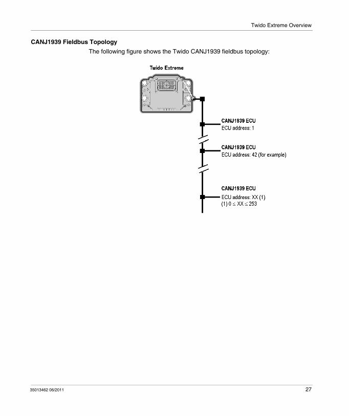
CANJ1939 Fieldbus ConnectionThe CANJ1939 architecture of a Twido Extreme system consists of:
A Twido Extreme controller,A CANJ1939 fieldbus port installed on Twido Extreme controller,Up to 32 CANJ1939 objects exchanged on the bus, with addresses ranging from 0 to 253.
26 35013462 06/2011
Twido Extreme Overview
CANJ1939 Fieldbus TopologyThe following figure shows the Twido CANJ1939 fieldbus topology:
35013462 06/2011 27

Twido Extreme Overview
Modbus RTU and ASCII Communication
IntroductionThe Modbus RTU and ASCII protocols are used for:
programming Twido Extreme with the TwidoSuite available on a PC (with a modem or a Bluetooth connection),operating Twido Extreme using the display interface.
Programming Protocols CharacteristicsThe programming protocol uses a RS485 line and RS485 half duplex terminal port.
It is based on Modbus at 19200 bauds, no parity and 1 stop bit.
To use a protocol other than the programming protocol on the controller serial RS485 port (to use ASCII for example), you must apply 0 V to contact 22 (DPT) on the connector.
The ASCII and RTU Modbus characteristics are as follows:
Characteristics Modbus and ASCII Value
Speed 1200 to 38400 bauds
Parity None, odd or even
Stop Bit 1 or 2
Data Bits 7 (ASCII) or 8 (RTU)
28 35013462 06/2011
Twido Extreme Overview
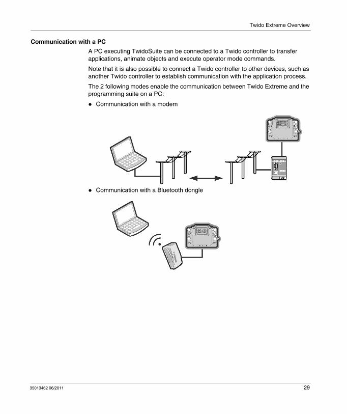
Communication with a PCA PC executing TwidoSuite can be connected to a Twido controller to transfer applications, animate objects and execute operator mode commands.
Note that it is also possible to connect a Twido controller to other devices, such as another Twido controller to establish communication with the application process.
The 2 following modes enable the communication between Twido Extreme and the programming suite on a PC:
Communication with a modem
Communication with a Bluetooth dongle
35013462 06/2011 29

Twido Extreme Overview
Ethernet Network ConnectionIt is possible to connect up to 3 Twido Extreme Controllers on an Ethernet network using the connection box XGS Z33ETH.
NOTE: The PC running the TwidoSuite application must be Ethernet-capable.
To set up an application with a connection box (XGS Z33ETH for example), use the wires as recommended down below.
Power supply connection using the XGS Z33ETH connection box.
NOTE: The connection must be made using a shielded cable with the strands connected to the chassis.
Description
Male M12 4-contact connector Contact number Signal
1 24 VDC
2 24 VDC
3 V -
4 V -
Connector Wrap Shielding
Power supply cable
30 35013462 06/2011
Twido Extreme Overview
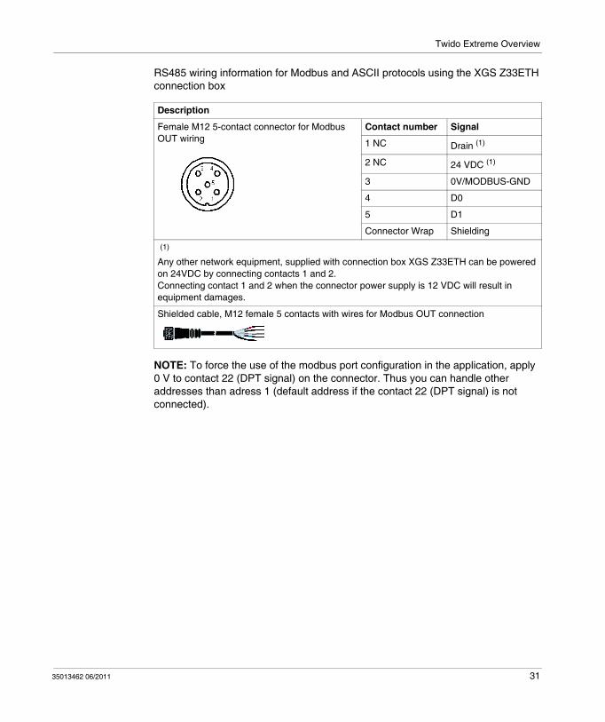
RS485 wiring information for Modbus and ASCII protocols using the XGS Z33ETH connection box
NOTE: To force the use of the modbus port configuration in the application, apply 0 V to contact 22 (DPT signal) on the connector. Thus you can handle other addresses than adress 1 (default address if the contact 22 (DPT signal) is not connected).
Description
Female M12 5-contact connector for Modbus OUT wiring
Contact number Signal
1 NC Drain (1)
2 NC 24 VDC (1)
3 0V/MODBUS-GND
4 D0
5 D1
Connector Wrap Shielding
(1) Any other network equipment, supplied with connection box XGS Z33ETH can be powered on 24VDC by connecting contacts 1 and 2.Connecting contact 1 and 2 when the connector power supply is 12 VDC will result in equipment damages.
Shielded cable, M12 female 5 contacts with wires for Modbus OUT connection
35013462 06/2011 31

Twido Extreme Overview
32 35013462 06/2011

35013462 06/2011
2
Twido Extreme Programmable ControllerInstallation35013462 06/2011
Installation
IntroductionThis chapter provides installation safety information, installation and mounting instructions for the Twido Extreme Controller and its options.
What’s in this Chapter?This chapter contains the following topics:
Topic Page
Power Supply Requirements 34
Twido Extreme Controller Dimensions 36
Environment Characteristics 37
Mounting Instructions 38
33

Installation
Power Supply Requirements
IntroductionThis section gives the voltage and current information required for a correct use of the controller and of the associated sensors.
Controller Power Supply Requirements
The controller must comply with the following electric requirements:
The voltages listed below are the steady state voltage ranges required between the +Battery and –Battery input contacts on the controller, whatever the temperature is:
Power Requirements
Power supply voltage from 9 VDC to 32 VDC
Power supply voltage in standby mode 310 mA for a 12 V system and 160 mA for a 24 V system
Battery voltage 12 VDC or 24 VDC:For a 12 VDC battery, ranging from 9 to 16VDC (%Q0.10 to %Q0.17 are available for power supply 9 to 16VDC)For a 24 VDC battery, ranging from 18 to 32VDC
Description Symbol Limit for a 12 V System
Limit for a 24 V System
Normal operating voltage rangeThe controller operates in normal conditions and during cranking.
Vop minimum: 9 Vmaximum: 16 V
minimum: 18 Vmaximum: 32 V
Non-operating voltage rangeThe controller does not need to boot or to function with the vehicle battery voltage. The voltage level depends on the system voltage (12 V or 24 V).
Vnop minimum: -32 V 24 Vmaximum: 9 V
minimum: -32 V 48 Vmaximum: 18 V
Non-destructive voltage rangeThe controller must not be damaged when exposed to any voltage for up to two minutes at 25° C (77° F). The voltage level depends on the system voltage (12 V or 24 V).
Vnd minimum: -32 V maximum: 24 V
minimum: -32 Vmaximum: 48 V
34 35013462 06/2011

Installation
Reverse Voltage RangeThe controller is protected against reverse voltage conditions.
NOTE: The controller does not function if reverse battery voltage is applied.
Sensors Power Supply RequirementsThe sensors can either be 5 V or 8 V sensors. They must comply with the following electric requirements:
NOTE: Moreover in stanby mode, the %Q0.18 output can be set and then to increase the power supply voltage of the controller.
Description Symbol Limits
Minimum Nominal Maximum
5 V sensor current output Io - - 200 mA
5 V sensor voltage output Vo 4.75 V 5 V 5.25 V
8 V sensor current output Io - - 70 mA
8 V sensor voltage output Vo 7.5 V 8.0 V 8.5 V
35013462 06/2011 35
Installation
Twido Extreme Controller Dimensions
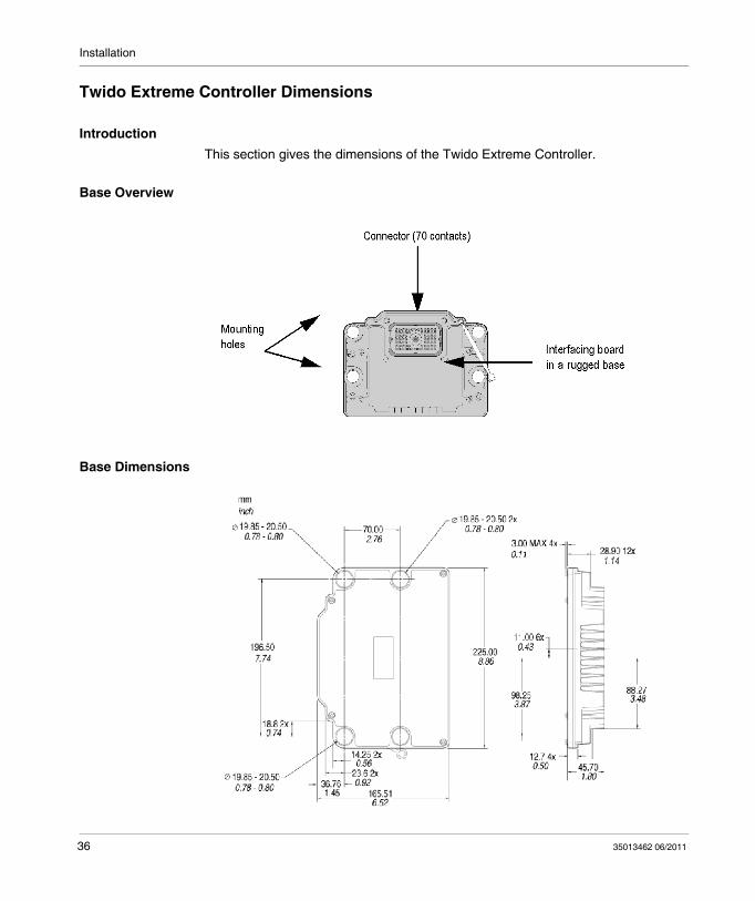
IntroductionThis section gives the dimensions of the Twido Extreme Controller.
Base Overview
Base Dimensions
36 35013462 06/2011

Installation
Environment Characteristics
IntroductionThis section provides the controller environmental operating conditions.
Environment ConditionsThe operating environmental characteristics are as follows:
Characteristic Description
Operating temperature range -40° C to +110° C (-40° F to +230° F)
System voltage 12 V and 24 V
Radiated immunity 20 MHz to 2.0 GHz at 30V/m
Storage temperature range -55° C to +155° C (-67° F to +311° F)
Output shortage tolerance 75% to 133% NSV (Nominal System Voltage)
Input shortage tolerance Between Input and Batt +/Batt-
Humidity tolerance 112% NSV, 90% relative humidity over operating temperature range
Salt spray tolerance 112% NSV with 5% salt spray for 48 hours at 38° C (100° F)
Chemical splash immunity Diesel fuel, engine and machine oil, SAE J1455 chemical agents, washer solvent, anti-freeze and degreaser
Vibration (shock isolated components tolerance)
9.45 Grms random vibration from 24-2000 Hz in three orthogonal planes, for six hours per plane
Moisture leakage (sealant pressure tolerance)
+/- 35 kPa (+/- 5.1 psi) against water and water vapor
Electrostatic environment Zero damage during exposure to electrostatic painting process
Shock resistance Vertical Max. acceleration 50 G 10 shock pulses 5 msHorizontal Max. acceleration 20 G 10 shock pulses 5 ms
35013462 06/2011 37

Installation
Mounting Instructions
IntroductionThis section provides information to mount a Twido Twido Extreme Controller.
It includes safety information and mounting instructions:
to connect the battery, to seal a connector kit, to mount Twido Extreme.
Installation Safety Information
DANGERRISKS OF ELECTRIC SHOCK
Turn power off before installing, removing, wiring, or maintaining.Do not repair or modify the controller.
Failure to follow these instructions will result in death or serious injury.
WARNINGLOSS OF CONTROL
The designer of any control scheme must consider the potential failure modes of control paths and, for certain critical control functions, provide a means to achieve a safe state during and after a path failure. Examples of critical control functions are emergency stop and overtravel stop, power outage and restart.Separate or redundant control paths must be provided for critical control functions.System control paths may include communication links. Consideration must be given to the implications of unanticipated transmission delays or failures of the link.Observe all accident prevention regulations and local safety guidelines.1
Each implementation of this equipment must be individually and thoroughly tested for proper operation before being placed into service.
Failure to follow these instructions can result in death, serious injury, or equipment damage.
38 35013462 06/2011

Installation
1 For additional information, refer to NEMA ICS 1.1 (latest edition), "Safety Guidelines for the Application, Installation, and Maintenance of Solid State Control" and to NEMA ICS 7.1 (latest edition), "Safety Standards for Construction and Guide for Selection, Installation and Operation of Adjustable-Speed Drive Systems" or their equivalent governing your particular location.
How to Connect the BatteryThe battery must be connected as follows:
CAUTIONINOPERABLE EQUIPMENT
Install the controller in the operating environment conditions described.Use the sensor power supply only for supplying power to sensors connected to the controller.For power line, use a fuse 32V with a maximum of 10 A for the input current and 10 s for fuse/breaker blow time.
Failure to follow these instructions can result in injury or equipment damage.
CAUTIONINOPERABLE EQUIPMENT
Ground the Controller as indicated in the figure above and connect the battery to the appropriate contacts on the connector.
Failure to follow these instructions can result in injury or equipment damage.
35013462 06/2011 39

Installation
How to Connect the Power SupplyThe controller automatically manages the power supply while respecting the voltage and current limits.
How to Seal a Connector KitTo seal a connector, comply with the following recommendations and instructions.
Step Description
1 Strip the wires following the strip length recommendations indicated in the figure below:
2 Inspect wire stripping as follows.
Check that:All strands are captivated.The bare wire strands are extended from the conductor crimp.Insulation is spaced from the conductor crimp area.
For more information on the crimp dimensions for each contact-wire combination, refer to Wiring Rules (see page 47).Use only the recommended type of socket terminals with the appropriate wire size and check that you secured the socket and the wire into the crimping tool, otherwise, adjust it.
3 Crimp the socket terminals using the connector Allen screw torque. The torque specification for the connector Allen screw is 6 +/- 1 N-m (53 +/-9 lb-in).
40 35013462 06/2011

Installation
4 Plug all socket terminals that you need in the connectors as indicated in the figure below. Push the socket terminal until to hear a click:
5 Fill all unused connector socket slots with plugs. Sealing integrity can only be provided with a correct installation of the cavity plugs in unused sockets:
For a correct installation, the plug cap must rest against the seal as indicated in the figure that follows.
Avoid inserting the plug cap in the hole
Step Description
35013462 06/2011 41

Installation
6 To install the routing harness, check that the connector seals are not stressed as this will cause the harness curve to be too close to the connector. To avoid seal distortion, place the wires perpendicular to the connector with a 90° bend radius curve, as shown in the following figure.
Wires must not bend close to the connector wire seal as they may cause inoperative sealing.
Step Description
42 35013462 06/2011

Installation
How to Mount a Twido Extreme ControllerTo mount a Twido Extreme controller, proceed as follows.
Step Description
1 If the connector is a kit to assemble (TWD FCN K70), fix the sockets as indicated in the section above to mount a sealed connector.
Add a cable duct if necessary.
2 Fix the connector into the base.
Fix the bolt at the center of the connector. The torque specification for the mounting bolt is 28 +/- 7 N-m (248 +/- 62 lb-in).
3 Fix the end bell to protect the connector.
35013462 06/2011 43
Installation
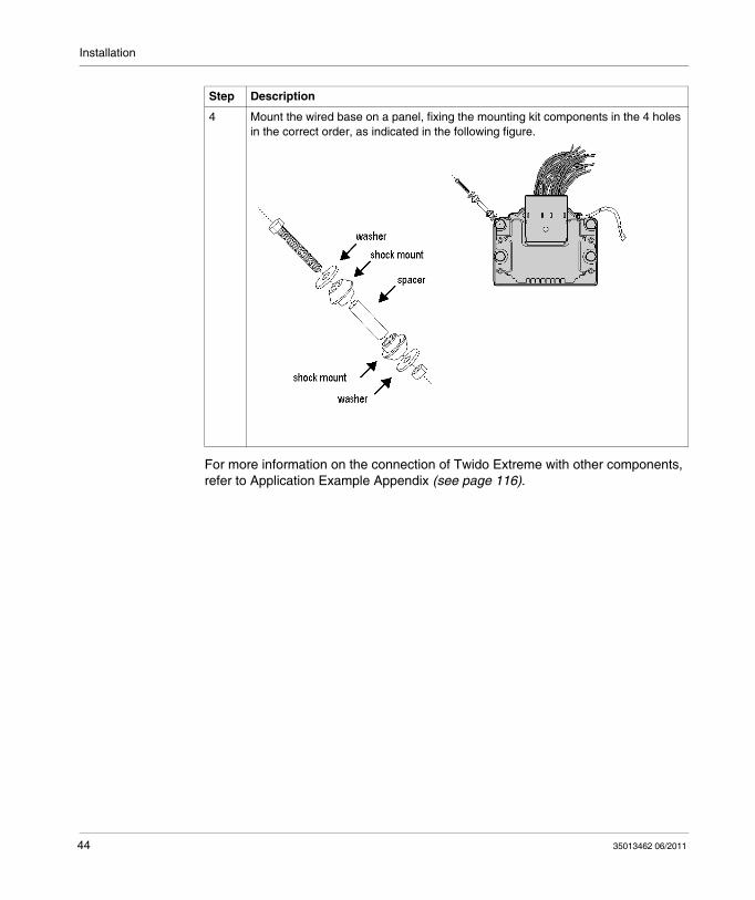
For more information on the connection of Twido Extreme with other components, refer to Application Example Appendix (see page 116).
4 Mount the wired base on a panel, fixing the mounting kit components in the 4 holes in the correct order, as indicated in the following figure.
Step Description
44 35013462 06/2011

35013462 06/2011
3
Twido Extreme Programmable ControllerWiring Rules and Recommendations35013462 06/2011
Wiring Rules and Recommendations
IntroductionThis chapter provides wiring rules, recommendations and wiring schematics.
What’s in this Chapter?This chapter contains the following sections:
Section Topic Page
3.1 Wiring Overview 46
3.2 Inputs Description 65
3.3 Outputs Description 83
45

Wiring Rules and Recommendations
3.1 Wiring Overview
IntroductionThis section gives general information on wiring.
What’s in this Section?This section contains the following topics:
Topic Page
Wiring Rules and Recommendations 47
Contacts Location on the Connector 50
Inputs and Outputs List Sorted by Type 52
Inputs and Outputs List Sorted by Number 55
RS485 Modbus Connection 58
Network Wiring 59
Inputs and Outputs Special Functions 62
46 35013462 06/2011
Wiring Rules and Recommendations
Wiring Rules and Recommendations
IntroductionSeveral rules must be followed when wiring a controller. Recommendations are provided to help you to comply with the rules.
1 For additional information, refer to NEMA ICS 1.1 (latest edition), "Safety Guidelines for the Application, Installation, and Maintenance of Solid State Control" and to NEMA ICS 7.1 (latest edition), "Safety Standards for Construction and Guide for Selection, Installation and Operation of Adjustable-Speed Drive Systems" or their equivalent governing your particular location.
DANGERRISKS OF ELECTRIC SHOCK
Remove all power from all devices before connecting or disconnecting inputs or outputs to any terminal or installing or removing the controller.
Failure to follow these instructions will result in death or serious injury.
WARNINGLOSS OF CONTROL
The designer of any control scheme must consider the potential failure modes of control paths and, for certain critical control functions, provide a means to achieve a safe state during and after a path failure. Examples of critical control functions are emergency stop and overtravel stop, power outage and restart.Separate or redundant control paths must be provided for critical control functions.System control paths may include communication links. Consideration must be given to the implications of unanticipated transmission delays or failures of the link.Observe all accident prevention regulations and local safety guidelines.1
Each implementation of this equipment must be individually and thoroughly tested for proper operation before being placed into service.
Failure to follow these instructions can result in death, serious injury, or equipment damage.
35013462 06/2011 47

Wiring Rules and Recommendations
Routing RulesThe rules for harness routing are as follows:
Clamp a wiring harness to both the controller and the metal support. Clamping reduces vibrations on the wire harness connector and provides routing control to prevent rubbing against other machine components and to limit motion in high vibration areas.The only points of contact are clamps and connectors.Use insulated P clips for wire harness support, as they are permanent.Use preformed bends for any bend beyond the controller clamp point.To avoid seal distortion of the wires entering the connector, the wire should exit perpendicular to the connector before curving. The harness bundle should have a bend radius greater than twice the harness diameter. Wires must not bend close to the connector wire seal as they may cause inoperative sealing.Unused connector socket slots must be filled with a sealing plug for ensure proper sealing against water/chemicals.
Sockets RulesThe sockets required to mount the connector are provided with the connector kit.
I/O Wiring RulesWires must be used with the recommended sockets in the paragraph above.
If the recommended wire is not used, parts may not be correctly sealed, moisture can affect the contacting pins and cause corrosion and/or crosstalk between pins.
The ground lines for I/O signals must be terminated as close to the controller as possible (max length 1m - 3.28ft).
When using auxiliary equipment with a distance longer than 3m (9.84ft) from the PLC, use CAN fieldbus for improved EMC immunity and easier cabling.
It is recommended that you use a connection terminal for the return I/O connections.
CAUTIONLOSS OF IP67 RATING
Strictly follow the routing and wiring rules indicated below. Not strictly following these rules can lead to poor seal protection against liquids or damaged wires produced by system vibration.
Failure to follow these instructions can result in injury or equipment damage.
48 35013462 06/2011
Wiring Rules and Recommendations
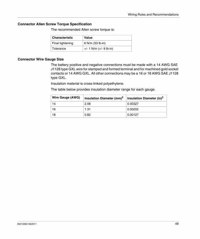
Connector Allen Screw Torque SpecificationThe recommended Allen screw torque is:
Connector Wire Gauge SizeThe battery positive and negative connections must be made with a 14 AWG SAE J1128 type GXL wire for stamped and formed terminal and for machined gold socket contacts or 14 AWG GXL. All other connections may be a 16 or 18 AWG SAE J1128 type GXL.
Insulation material is cross-linked polyethylene.
The table below provides insulation diameter range for each gauge.
Characteristic Value
Final tightening 6 N/m (53 lb-in)
Tolerance +/- 1 N/m (+/- 9 lb-in)
Wire Gauge (AWG) Insulation Diameter (mm)2 Insulation Diameter (in)2
14 2.08 0.00327
16 1.31 0.00202
18 0.82 0.00127
35013462 06/2011 49
Wiring Rules and Recommendations
Contacts Location on the Connector
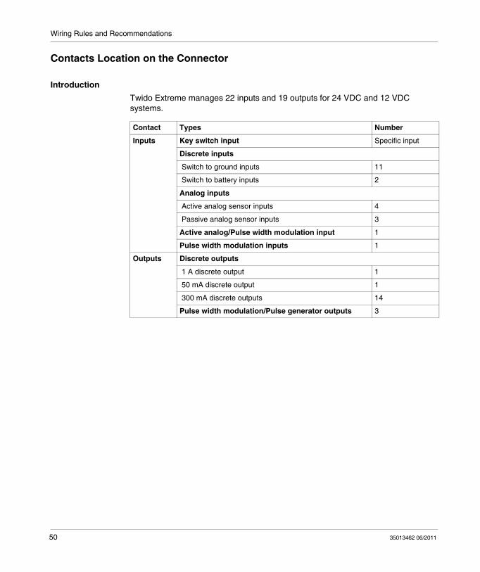
IntroductionTwido Extreme manages 22 inputs and 19 outputs for 24 VDC and 12 VDC systems.
Contact Types Number
Inputs Key switch input Specific input
Discrete inputs
Switch to ground inputs 11
Switch to battery inputs 2
Analog inputs
Active analog sensor inputs 4
Passive analog sensor inputs 3
Active analog/Pulse width modulation input 1
Pulse width modulation inputs 1
Outputs Discrete outputs
1 A discrete output 1
50 mA discrete output 1
300 mA discrete outputs 14
Pulse width modulation/Pulse generator outputs 3
50 35013462 06/2011

Wiring Rules and Recommendations
Connectors LocationThe following figure illustrates the contacts and their location on the connector.
35013462 06/2011 51

Wiring Rules and Recommendations
Inputs and Outputs List Sorted by Type
IntroductionThis section lists the contacts according to their type and function.
Inputs/Outputs List
Function I/O Identifier Contact Number
Key switch input Key switch 70
Communication strap DPT 22
Discrete input 0 I0.0 36
Discrete input 1 I0.1 28
Discrete input 2 I0.2 20
Discrete input 3 I0.3 11
Discrete input 4 I0.4 19
Discrete input 5 I0.5 29
Discrete input 6 I0.6 10
Discrete input 7 I0.7 30
Discrete input 8 I0.8 21
Discrete input 9 I0.9 9
Discrete input 10 I0.10 38
I0.0 to I0.10 return I0.0 to I0.10 return 37
Discrete input 11 I0.11 2
Discrete input 12 I0.12 3
Analog input 0 I0.13/IW0.0 18
Analog input 1 I0.14/IW0.1 24
Analog input 2 I0.15/IW0.2 14
Analog input 3 I0.16/IW0.3 25
Analog input 4 I0.17/IW0.4 15
Analog input 5 I0.18/IW0.5 32
Analog input 19 I0.19/IW0.6 35
Non configurable active analog sensor/PWM IW0.7 16
PWM input 1 + IW0.8 6
PWM input 1 - IW0.8 7
PWM input 1 shield IW0.8 8
52 35013462 06/2011

Wiring Rules and Recommendations
D1 D1 4
D0 D0 5
5 V sensor power supply 5 V 200 mA 26
Contact 26 5 V return Contact 26 5 V return 34
5 V sensor power supply 5 V 200 mA 45
Contact 45 5 V return Contact 45 5 V return 44
8 V sensor power supply 8 V 70 mA 17
35 mA discrete sink/source output 0 Q0.0/PWM0/PLS0 46
35 mA discrete sink/source output 1 Q0.1/PWM1/PLS1 47
40 mA discrete sink/source output 2 Q0.2/PWM2/PLS2 39
50 mA discrete source output 3 Q0.3 1
1 A discrete source output 4 Q0.4 60
1 A discrete source output 4 return 1 A RETURN - Q0.4 50
300 mA discrete sink output 5 Q0.5 31
300 mA discrete sink output 6 Q0.6 12
300 mA discrete sink output 7 Q0.7 13
300 mA discrete sink output 8 Q0.8 43
300 mA discrete sink output 9 Q0.9 42
300 mA discrete sink output 10 Q0.10 66
300 mA discrete sink output 11 Q0.11 65
300 mA discrete sink output 12 Q0.12 64
300 mA discrete sink output 13 Q0.13 63
300 mA discrete sink output 14 Q0.14 67
300 mA discrete sink output 15 Q0.15 54
300 mA discrete sink output 16 Q0.16 62
300 mA discrete sink output 17 Q0.17 53
300 mA discrete sink output 18 Q0.18 23
CANopen network shield CANopen shield 40
CANopen+ network CANopen+ 48
CANopen- network CANopen- 58
CANJ1939 network shield CANJ1939 shield 51
CANJ1939+ network CANJ1939+ 52
CANJ1939- network CANJ1939- 61
Fast counter return FC Shield 33
Function I/O Identifier Contact Number
35013462 06/2011 53

Wiring Rules and Recommendations
Fast counter input Fast counter input 41
Battery+ Battery+ 56
Battery+ Battery+ 57
Battery- Battery- 55
Battery- Battery- 68
Battery- Battery- 69
Unused Unused 27
Unused Unused 49
Unused Unused 59
Function I/O Identifier Contact Number
54 35013462 06/2011

Wiring Rules and Recommendations
Inputs and Outputs List Sorted by Number
IntroductionThis section lists the contacts according to their number.
Inputs/Outputs List
Contact Number
Function I/O Identifier
1 50 mA discrete source output 3 Q0.3
2 Discrete input 11 I0.11
3 Discrete input 12 I0.12
4 D1 D1
5 D0 D0
6 PWM input 1 + IW0.8
7 PWM input 1 - IW0.8
8 PWM input 1 shield IW0.8
9 Discrete input 9 I0.9
10 Discrete input 6 I0.6
11 Discrete input 3 I0.3
12 300 mA discrete sink output 6 Q0.6
13 300 mA discrete sink output 7 Q0.7
14 Analog input 2 I0.15/IW0.2
15 Analog input 4 I0.17/IW0.4
16 Non configurable active analog sensor/PWM IW0.7
17 8 V sensor power supply 8 V 70 mA
18 Analog input 0 I0.13/IW0.0
19 Discrete input 4 I0.4
20 Discrete input 2 I0.2
21 Discrete input 8 I0.8
22 Communication strap DPT
23 300 mA discrete sink output 18 Q0.18
24 Analog input 1 I0.14/IW0.1
25 Analog input 3 I0.16/IW0.3
26 5 V sensor power supply 5 V 200 mA
27 Unused Unused
35013462 06/2011 55

Wiring Rules and Recommendations
28 Discrete input 1 I0.1
29 Discrete input 5 I0.5
30 Discrete input 7 I0.7
31 300 mA discrete sink output 5 Q0.5
32 Analog input 5 I0.18/IW0.5
33 Fast counter return FC Shield
34 Contact 26 5 V return Contact 26 5 V return
35 Analog input 19 I0.19/IW0.6
36 Discrete input 0 I0.0
37 I0.0 to I0.10 return I0.0 to I0.10 return
38 Discrete input 10 I0.10
39 40 mA discrete sink/source output 2 Q0.2/PWM2/PLS2
40 CANopen network shield CANopen shield
41 Fast counter input Fast counter input
42 300 mA discrete sink output 9 Q0.9
43 300 mA discrete sink output 8 Q0.8
44 Contact 45 5 V return Contact 45 5 V return
45 5 V sensor power supply 5 V 200 mA
46 35 mA discrete sink/source output 0 Q0.0/PWM0/PLS0
47 35 mA discrete sink/source output 1 Q0.1/PWM1/PLS1
48 CANopen+ network CANopen+
49 Unused Unused
50 1 A discrete source output 4 return 1 A RETURN - Q0.4
51 CANJ1939 network shield CANJ1939 shield
52 CANJ1939+ network CANJ1939+
53 300 mA discrete sink output 17 Q0.17
54 300 mA discrete sink output 15 Q0.15
55 Battery- Battery-
56 Battery+ Battery+
57 Battery+ Battery+
58 CANopen- network CANopen-
59 Unused Unused
60 1 A discrete source output 4 Q0.4
61 CANJ1939- network CANJ1939-
Contact Number
Function I/O Identifier
56 35013462 06/2011

Wiring Rules and Recommendations
62 300 mA discrete sink output 16 Q0.16
63 300 mA discrete sink output 13 Q0.13
64 300 mA discrete sink output 12 Q0.12
65 300 mA discrete sink output 11 Q0.11
66 300 mA discrete sink output 10 Q0.10
67 300 mA discrete sink output 14 Q0.14
68 Battery- Battery-
69 Battery- Battery-
70 Key switch input Key switch
Contact Number
Function I/O Identifier
35013462 06/2011 57
Wiring Rules and Recommendations
RS485 Modbus Connection
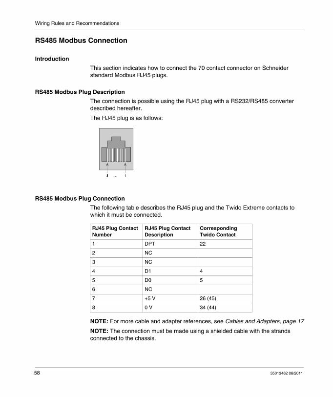
IntroductionThis section indicates how to connect the 70 contact connector on Schneider standard Modbus RJ45 plugs.
RS485 Modbus Plug DescriptionThe connection is possible using the RJ45 plug with a RS232/RS485 converter described hereafter.
The RJ45 plug is as follows:
RS485 Modbus Plug ConnectionThe following table describes the RJ45 plug and the Twido Extreme contacts to which it must be connected.
NOTE: For more cable and adapter references, see Cables and Adapters, page 17
NOTE: The connection must be made using a shielded cable with the strands connected to the chassis.
RJ45 Plug Contact Number
RJ45 Plug Contact Description
Corresponding Twido Contact
1 DPT 22
2 NC
3 NC
4 D1 4
5 D0 5
6 NC
7 +5 V 26 (45)
8 0 V 34 (44)
58 35013462 06/2011

Wiring Rules and Recommendations
Network Wiring
Introduction The controller is equipped with the following buses:
2 CAN buses (CANopen and CANJ1939) with a 10 kΩ slope control resistor1 Modbus network
CAN network locations on the connector are as follows.
CANopen Network Specifications CANopen is designed with 120 Ω termination resistor.
To set up a network, it is recommended to use Schneider CANopen cable: TSX CANCA50 for a 50 m (164 ft) cable, TSX CANCA100 for 100 m (328 ft) and TSX CANCA300 for 300 m (984 ft).
The CANopen bus can communicate at a maximum bit rate of 500 kbit/s.
An external120 Ω terminating resistor is required for CAN connection next to the controller (see the figure down below).Another terminating resistor is required at the opposite end of the CANopen cable.
NOTE: The CAN_GND wire must be connected to the BAT- controller contact.
The high-speed connection for this interface is controlled by software.
Function Contact number
CANopen+ 48
CANopen- 58
CAN_GND 55
CANopen shield 40
CANJ1939+ 52
CANJ1939- 61
CANJ1939 shield 51
35013462 06/2011 59

Wiring Rules and Recommendations
CANopen Wiring Example
CANJ1939 Network Specifications CANJ1939 must have a twisted cable complying with SAE J1939-11 or J1939-15 wiring standards. It is recommended to use Schneider CANopen cable: TSX CANCA50 for a 50 m (164 ft) cable, TSX CANCA100 for 100 m (328 ft) and TSX CANCA300 for 300 m (984 ft).
The SAE J1939 CAN bus operates at 250 kbit/s.
It requires an external terminating resistor pair to work properly. This bus has a dedicated AC-coupled shielding connection. Any twisted cable that meets SAE J1939-11 or J1939-15 can be used with this bus.
CANJ1939 Wiring Example
60 35013462 06/2011
Wiring Rules and Recommendations
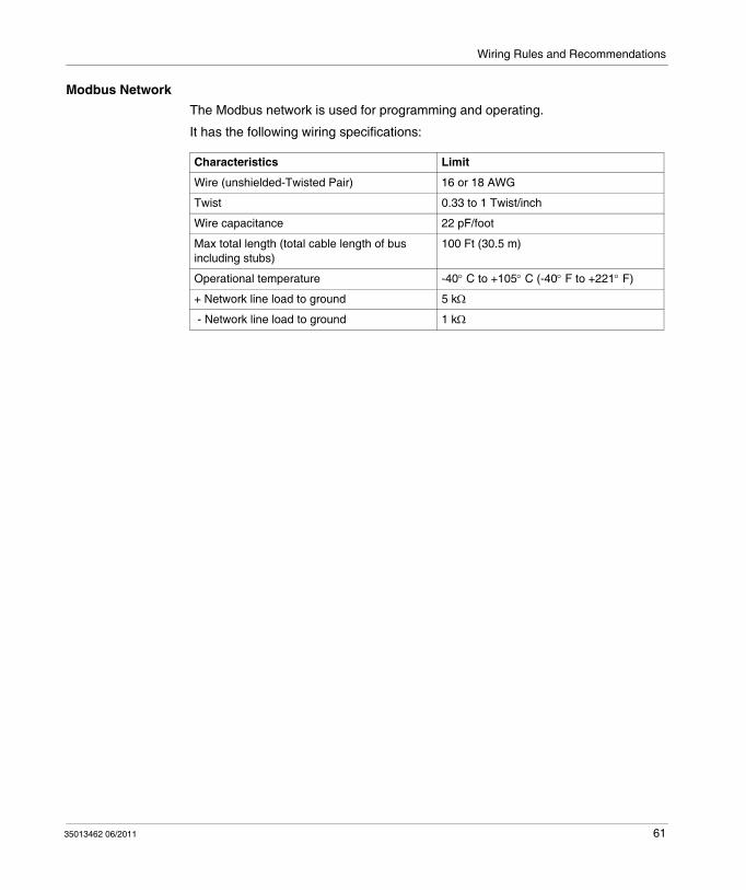
Modbus NetworkThe Modbus network is used for programming and operating.
It has the following wiring specifications:
Characteristics Limit
Wire (unshielded-Twisted Pair) 16 or 18 AWG
Twist 0.33 to 1 Twist/inch
Wire capacitance 22 pF/foot
Max total length (total cable length of bus including stubs)
100 Ft (30.5 m)
Operational temperature -40° C to +105° C (-40° F to +221° F)
+ Network line load to ground 5 kΩ
- Network line load to ground 1 kΩ
35013462 06/2011 61

Wiring Rules and Recommendations
Inputs and Outputs Special Functions
IntroductionThis section provides information on inputs and outputs dedicated to special functions.
Turning the Controller ON/OFFTwido Extreme has no internal battery. The key switch input is used to turn the controller ON and OFF.
When the key switch is turned ON, the controller applies standard operating modes.When the key switch is turned ON for a restart, the controller starts, calculates the checksum and restarts on WARM start if the checksum is equal to the value calculated when it was turned OFF or it executes a cold start.When the key switch is turned OFF, the controller runs the run time clock update, executes a checksum of the RAM and turns off the micro-controller. Note that if the controller is in a RUN state, it remains in the RUN state without executing the code.
For detailed information, see Key Switch Input, page 68.
RUN/STOP InputThe RUN/STOP input is a special function that can be assigned to one of the controller 13 first inputs. This function is used to start or to stop a program.
At power up, if configured, the controller state is set by the RUN/STOP input:
if RUN/STOP input is at state 0, the controller is in STOP mode.
if RUN/STOP input is at state 1, the controller is in RUN mode.
While the controller is powered, a rising edge on the RUN/STOP input state sets the controller to RUN.
The controller is stopped if the RUN/STOP input is set to 0.
If the RUN/STOP input is set to 0, the controller ignores any RUN command from a connected PC.
The optional status output gives the result of the state transition.
Status OutputThe controller status output is a special function assigned to Q0.3.
At power up, the controller status output is set to 1 if the controller is in RUN mode without errors.
62 35013462 06/2011

Wiring Rules and Recommendations
This function can be used in circuits external to the controller to control, for example, the power supply to the output devices.
For detailed information, see 50 mA Discrete Output, page 87
Fast Counting The extreme base controller has 1 fast counter including a single up and down counter function with a maximum frequency of 10 kHz.
The single up and single down counter functions enable up-counting or down-counting of pulses (rising edges) on a digital I/O. These functions enable counting of pulses from 0 to 65535 in single-word mode and from 0 to 4294967295 in double-word mode.
Example of fast counter wiring
Fast Counting input electrical requirements are as follows.
Symbol Description Limits
Minimum Nominal Maximum
VIL Input low voltage (single-ended) 1 V
VIH Input high voltage (single-ended) 4 V
RL Sensor resistance 60 Ω 1950 Ω
Low pass cutoff filter 4000 Hz
fIN Input frequency range 50 Hz ± 0.5 Hz 10 kHz
HL Sensor inductance 40 mH 550 mH
td Single end time delay 20 μs 25 μs 30 μs
ZDEL Zero crossing output delay 25 μs 35 μs 45 μs
35013462 06/2011 63

Wiring Rules and Recommendations
Pulse Width Modulation (PWM) Outputs The PWM is a special function that can be assigned to 3 outputs (Q0.0, Q0.1 or Q0.2).
A user-defined function block generates a signal on output Q0.0, Q0.1 or Q0.2. This signal has a constant period with the possibility of varying the duty cycle.
PWM outputs can be used in hydraulic mode to handle proportional valves
The controller supports 3 PWM generators in single-word and double-word functions.
NOTE: IW0.7 and IW0.8 are PWM inputs.
Pulse (PLS) Generator Outputs The PLS is a special function that can be assigned to 3 outputs (Q0.0, Q0.1 or Q0.2).
A user-defined function block generates a signal on output Q0.0, Q0.1 or Q0.2. This signal has a variable period and a constant duty cycle
The controller supports 3 PLS generators in single-word and double-word functions.
64 35013462 06/2011
Wiring Rules and Recommendations
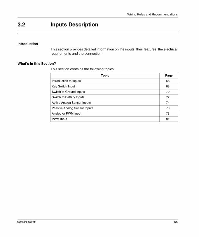
3.2 Inputs Description
IntroductionThis section provides detailed information on the inputs: their features, the electrical requirements and the connection.
What’s in this Section?This section contains the following topics:
Topic Page
Introduction to Inputs 66
Key Switch Input 68
Switch to Ground Inputs 70
Switch to Battery Inputs 72
Active Analog Sensor Inputs 74
Passive Analog Sensor Inputs 76
Analog or PWM Input 78
PWM Input 81
35013462 06/2011 65
Wiring Rules and Recommendations
Introduction to Inputs
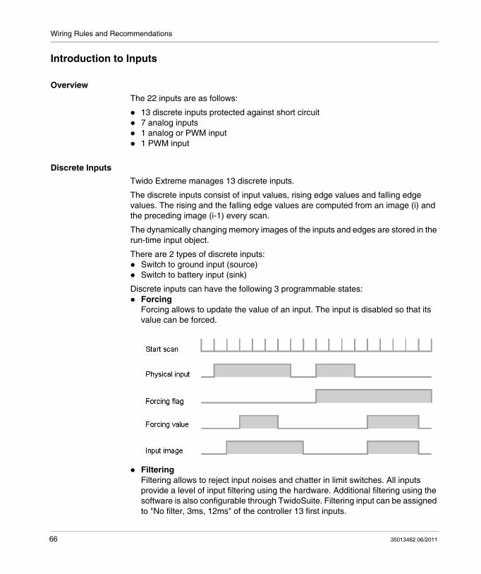
OverviewThe 22 inputs are as follows:
13 discrete inputs protected against short circuit7 analog inputs1 analog or PWM input1 PWM input
Discrete InputsTwido Extreme manages 13 discrete inputs.
The discrete inputs consist of input values, rising edge values and falling edge values. The rising and the falling edge values are computed from an image (i) and the preceding image (i-1) every scan.
The dynamically changing memory images of the inputs and edges are stored in the run-time input object.
There are 2 types of discrete inputs:Switch to ground input (source)Switch to battery input (sink)
Discrete inputs can have the following 3 programmable states:ForcingForcing allows to update the value of an input. The input is disabled so that its value can be forced.
FilteringFiltering allows to reject input noises and chatter in limit switches. All inputs provide a level of input filtering using the hardware. Additional filtering using the software is also configurable through TwidoSuite. Filtering input can be assigned to "No filter, 3ms, 12ms" of the controller 13 first inputs.
66 35013462 06/2011

Wiring Rules and Recommendations
LatchingLatching allows to memorize pulses with a duration inferior to the controller scan time.When a pulse is shorter than a scan and has a value greater than or equal to 1 ms, the controller latches the pulse which is then updated in the next scan.Latching input can only be enabled for the first 4 inputs (I0.0 to I0.3).
Analog InputsTwido Extreme manages 7 analog inputs (0-5 VDC). There are 2 types of analog inputs:
Active analog sensor inputsPassive analog sensor inputs
Analog/PWM InputTwido Extreme manages 1 input which is either an active analog input or a PWM input.
PWM InputTwido Extreme manages 1 input used only as a PWM input.
35013462 06/2011 67

Wiring Rules and Recommendations
Key Switch Input
FeaturesThe key switch input is used to:
turn the controller ON and OFF,set the controller in standby mode.
NOTE: Power supply must not be turned off to proceed to these operations so that the controller can automatically execute a WARM restart. If power supply is turned off, the controller proceeds to a COLD restart, date and time are not maintained.
The input must be set to1 to start the controller and to 0 to place it in standby mode provided that power supply has not been turned off.
Description
Electrical CharacteristicsKey switch input electrical requirements are as follows.
NOTE: (1): Level input is unspecified for voltage between 0.65 VBAT and 0.8 VBAT.
Type Discrete
Number 1
Identifier Key switch
Contact position 70
Symbol Description Limits
Minimum Nominal Maximum
VIN Input signal voltage (DC) -1 V 0 to 32 V 48 V
VIL (1) Low-level input voltageLogic 0 = VIN inferior or equal to VIL
0.65 VBAT
VIH (1) High-level input voltageLogic 1 = VIN superior or equal to VIH
0.8 VBAT
RPD Pull-down resistance to controller ground
9.5 kΩ 10 kΩ 10.5 kΩ
τSWK_O Noise filter time constant at 25° C (77° F), single pole RC type
600 μs
68 35013462 06/2011
Wiring Rules and Recommendations
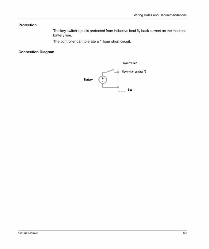
ProtectionThe key switch input is protected from inductive load fly back current on the machine battery line.
The controller can tolerate a 1 hour short circuit.
Connection Diagram
35013462 06/2011 69
Wiring Rules and Recommendations
Switch to Ground Inputs
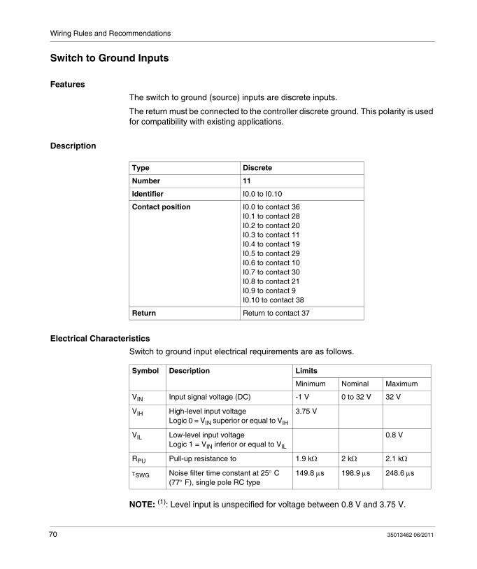
FeaturesThe switch to ground (source) inputs are discrete inputs.
The return must be connected to the controller discrete ground. This polarity is used for compatibility with existing applications.
Description
Electrical CharacteristicsSwitch to ground input electrical requirements are as follows.
NOTE: (1): Level input is unspecified for voltage between 0.8 V and 3.75 V.
Type Discrete
Number 11
Identifier I0.0 to I0.10
Contact position I0.0 to contact 36 I0.1 to contact 28 I0.2 to contact 20 I0.3 to contact 11 I0.4 to contact 19 I0.5 to contact 29 I0.6 to contact 10 I0.7 to contact 30 I0.8 to contact 21 I0.9 to contact 9 I0.10 to contact 38
Return Return to contact 37
Symbol Description Limits
Minimum Nominal Maximum
VIN Input signal voltage (DC) -1 V 0 to 32 V 32 V
VIH High-level input voltageLogic 0 = VIN superior or equal to VIH
3.75 V
VIL Low-level input voltage Logic 1 = VIN inferior or equal to VIL
0.8 V
RPU Pull-up resistance to 1.9 kΩ 2 kΩ 2.1 kΩ
τSWG Noise filter time constant at 25° C (77° F), single pole RC type
149.8 μs 198.9 μs 248.6 μs
70 35013462 06/2011

Wiring Rules and Recommendations
ProtectionThe controller can tolerate a 1 hour short circuit.
Connection Diagram
35013462 06/2011 71

Wiring Rules and Recommendations
Switch to Battery Inputs
FeaturesThe switch to battery (sink) inputs are discrete inputs. They are pulled-down to the controller ground.
There must be 2 switches to +Bat inputs on the controller. This polarity is used for compatibility with existing applications.
Description
Electrical CharacteristicsSwitch to battery input electrical requirements are as follows.
NOTE: (1): Level input is unspecified for voltage between 0.65 VBAT and 0.85 VBAT.
ProtectionThe controller can tolerate a 1 hour short circuit.
Type Discrete
Number 2
Identifier I0.11 and I0.12
Contact position I0.11 to contact 2I0.12 to contact 3
Symbol Description Limits
Minimum Nominal Maximum
VIH (1) High-level input voltage Logic 1 = VIN superior or equal to VIH
0.85 VBAT
VIL (1) Low-level input voltage Logic 0 = VIN inferior or equal to VIL
0.65 VBAT
VIN Input signal voltage (DC) -1 V 0 to 32 V 48 V
RPD Pull-down resistance to the controller ground
9.5 kΩ 10 kΩ 10.5 kΩ
τSWB Noise filter time constant at 25° C (77° F), single pole RC type
600 μs
72 35013462 06/2011

Wiring Rules and Recommendations
Connection Diagram
35013462 06/2011 73

Wiring Rules and Recommendations
Active Analog Sensor Inputs
FeaturesActive sensors use an external power supply to provide measure signals. The sensors behave as active dipoles with a current, tension or load type.
Active sensors function as generators. They are scaled at 1 without adaptation.
The analog to discrete converter takes the controller components obsolescence into account.
These inputs can function as switch to ground (source) inputs, however the noise filter and pull-up values do not meet the switch to ground (source) inputs specifications.
Analog inputs can be used for current sensors (0-20 mA) with a resistor plugged between the common reference point and the input.
Description
Electrical CharacteristicsActive analog sensor input electrical requirements are as follows.
Type Analog
Number 4
Identifier IW0.0 to IW0.3
Contact position IW0.0/I0.13 to contact 18 IW0.1/I0.14 to contact 24 IW0.2/I0.15 to contact 14IW0.3/I0.16 to contact 25
Symbol Description Limits
Minimum Nominal Maximum
EADC ADC error 0 - +/- 125 mV
VIN Input signal voltage (DC) -1 V 0 V to 5 V 32 V
VRD Nominal reading voltage range 0 V - 5 V
VPU Pull-up voltage - 13 V -
RPU Pull-up resistance, internal at 25°C (77°C)
20.9 kΩ 22 kΩ 23.1 kΩ
τAIN_ACT Noise filter time constant at 25°C (77°C), single pole RC type
3.87 ms 5.10 ms 6.43 ms
Value (QADC) refresh time - 700 μs -
74 35013462 06/2011

Wiring Rules and Recommendations
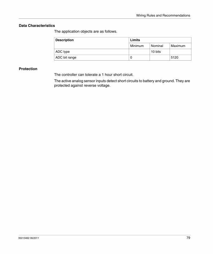
Data CharacteristicsThe application objects are as follows.
ProtectionThe controller can tolerate a 1 hour short circuit.
The active analog sensor inputs detect short circuits to battery and ground. They are protected against reverse voltage.
Connection Diagram
Description Limits
Minimum Nominal Maximum
ADC type 10 bits
ADC bit range 0 5120
35013462 06/2011 75
Wiring Rules and Recommendations
Passive Analog Sensor Inputs
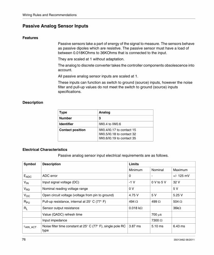
FeaturesPassive sensors take a part of energy of the signal to measure. The sensors behave as passive dipoles which are resistive. The passive sensor must have a load of between 0.018KOhms to 36KOhms that is connected to the input.
They are scaled at 1 without adaptation.
The analog to discrete converter takes the controller components obsolescence into account.
All passive analog sensor inputs are scaled at 1.
These inputs can function as switch to ground (source) inputs, however the noise filter and pull-up values do not meet the switch to ground (source) inputs specifications.
Description
Electrical CharacteristicsPassive analog sensor input electrical requirements are as follows.
Type Analog
Number 3
Identifier IW0.4 to IW0.6
Contact position IW0.4/I0.17 to contact 15 IW0.5/I0.18 to contact 32 IW0.6/I0.19 to contact 35
Symbol Description Limits
Minimum Nominal Maximum
EADC ADC error 0 - +/- 125 mV
VIN Input signal voltage (DC) -1 V 0 V to 5 V 32 V
VRD Nominal reading voltage range 0 V 5 V
VOC Open circuit voltage (voltage from pin to ground) 4.75 V 5 V 5.25 V
RPU Pull-up resistance, internal at 25° C (77° F) 494 Ω 499 Ω 504 Ω
RL Sensor output resistance 0.018 kΩ 36kΩ
Value (QADC) refresh time 700 μs
Input impedance 7300 Ω
τAIN_ACT Noise filter time constant at 25° C (77° F), single pole RC type
3.87 ms 5.10 ms 6.43 ms
76 35013462 06/2011

Wiring Rules and Recommendations
Data CharacteristicsThe application objects are as follows.
ProtectionThe controller can tolerate a 1 hour short circuit.
The active analog sensor inputs detect short circuits to battery and ground as well as open circuit. They are protected against reverse voltage.
Connection Diagram
Measure represents the value of %IW0.4, %IW0.5,%IW0.6
Configuration min value = 0 by default
Configuration max value = 5120 by default
Description Limits
Minimum Nominal Maximum
ADC type 10 bits
ADC bit range 0 5120
35013462 06/2011 77

Wiring Rules and Recommendations
Analog or PWM Input
FeaturesThis input is either an active analog input or it can be configured as a PWM (pulse width modulation) input.
The channel cannot be both simultaneously.
Description
Electrical CharacteristicsPulse width modulation input electrical requirements are as follows.
Type Analog or PWM
Number 1
Identifier IW0.7
Contact position IW0.7 to contact 16
Symbol Description Limits
Minimum Nominal Maximum
EADC ADC error 0 - +/- 125 mV
VIN Input signal voltage (DC) -1 V 0 V to 5 V 32 V
VPU Pull-up voltage 13 V
VRD Nominal reading voltage range 0 V 5 V
RPU Pull-up resistance, internal at 25°C (77° F)
4.8 kΩ 5.1 kΩ 5.4 kΩ
ACCPWM PWM measurement accuracy 1 %
DI Input PWM duty cycle 5 % 95 %
fIN Input frequency range 90 Hz 600 Hz
τAIN_ACT Active analog input noise filter time constant at 25° C (77° F), single pole RC type
3.87 ms 5.10 ms 6.43 ms
τPWM_I PWM noise filter time constant at 25° C (77° F), single pole RC type
50 μs 60 μs 70 μs
78 35013462 06/2011
Wiring Rules and Recommendations
Data CharacteristicsThe application objects are as follows.
ProtectionThe controller can tolerate a 1 hour short circuit.
The active analog sensor inputs detect short circuits to battery and ground. They are protected against reverse voltage.
Description Limits
Minimum Nominal Maximum
ADC type 10 bits
ADC bit range 0 5120
35013462 06/2011 79

Wiring Rules and Recommendations
Connection Diagram
80 35013462 06/2011
Wiring Rules and Recommendations
PWM Input
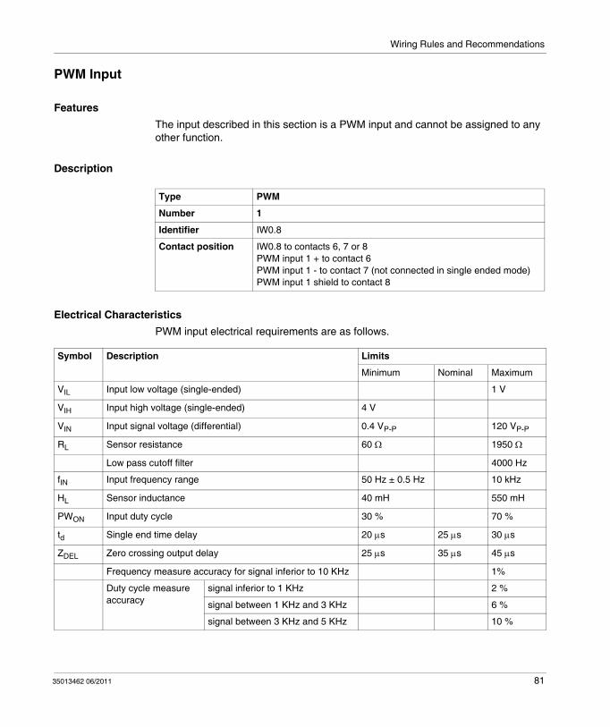
FeaturesThe input described in this section is a PWM input and cannot be assigned to any other function.
Description
Electrical CharacteristicsPWM input electrical requirements are as follows.
Type PWM
Number 1
Identifier IW0.8
Contact position IW0.8 to contacts 6, 7 or 8PWM input 1 + to contact 6PWM input 1 - to contact 7 (not connected in single ended mode)PWM input 1 shield to contact 8
Symbol Description Limits
Minimum Nominal Maximum
VIL Input low voltage (single-ended) 1 V
VIH Input high voltage (single-ended) 4 V
VIN Input signal voltage (differential) 0.4 VP-P 120 VP-P
RL Sensor resistance 60 Ω 1950 Ω
Low pass cutoff filter 4000 Hz
fIN Input frequency range 50 Hz ± 0.5 Hz 10 kHz
HL Sensor inductance 40 mH 550 mH
PWON Input duty cycle 30 % 70 %
td Single end time delay 20 μs 25 μs 30 μs
ZDEL Zero crossing output delay 25 μs 35 μs 45 μs
Frequency measure accuracy for signal inferior to 10 KHz 1%
Duty cycle measure accuracy
signal inferior to 1 KHz 2 %
signal between 1 KHz and 3 KHz 6 %
signal between 3 KHz and 5 KHz 10 %
35013462 06/2011 81

Wiring Rules and Recommendations
NOTE: (1): Level input is unspecified for voltage between 1 V and 4 V.
ProtectionThe controller can tolerate a 1 hour short circuit.
Zero crossing falling edge is triggered.
Maximum 1% frequency distortion is measured between the controller contact to the CPU contact.
Connection Diagram
Pulse width measure accuracy
signal inferior to 1 KHz 2 %
signal between 1 KHz and 3 KHz 8 %
signal between 3 KHz and 5 KHz 15 %
82 35013462 06/2011

Wiring Rules and Recommendations
3.3 Outputs Description
IntroductionThis section provides detailed information on the outputs: their features, the electrical requirements and the connection.
What’s in this Section?This section contains the following topics:
Topic Page
Introduction to Outputs 84
1 A Discrete Output 85
50 mA Discrete Output 87
300 mA Discrete Outputs 89
PWM/PLS Outputs 92
35013462 06/2011 83

Wiring Rules and Recommendations
Introduction to Outputs
OverviewThe 19 outputs are as follows:
16 discrete outputs protected against short circuit: 1 A driver: 1 output,
50 mA driver: 1 output
300 mA driver: 14 outputs with either a 85 V load dump or a 150 V load dump
3 PWM/PLS outputs
Output State Outputs can have a forcing programmable state.
Forcing allows to update the value of an output. The output is disabled so that its value can be forced.
When unforcing occurs, the value of the bit remains the same as the last forced value until such time as a forcing operation or user logic instruction overwrites that image bit. Output scanning does not happen unless the controller is in a RUN or NO_CONFIG (test) state with no application download started.
The NO_CONFIG state allows wiring tests. To perform wiring tests in a non configured mode, set bit S8 to 0 and use TwidoAdjust to change the output object value. The system copies this value to the physical output. If you set bit S8 to 1, physical outputs will be at 0.
NOTE: Forcing overrides any output except the status output
NOTE: Risks of breaking may occur when the relay coil connected to the controller output opens. To avoid overvoltage, you are recommended to connect a protection module to the relay coil.
84 35013462 06/2011
Wiring Rules and Recommendations
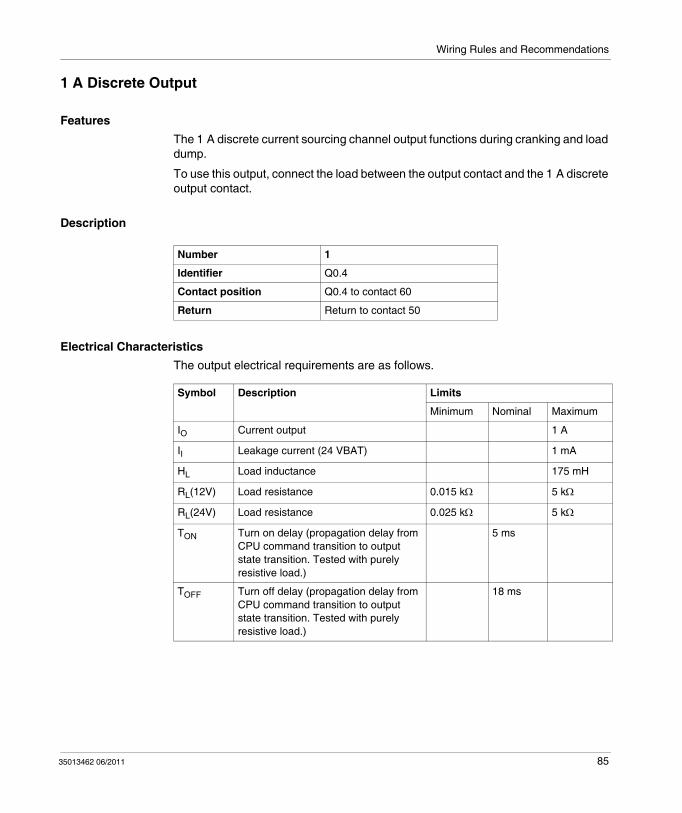
1 A Discrete Output
FeaturesThe 1 A discrete current sourcing channel output functions during cranking and load dump.
To use this output, connect the load between the output contact and the 1 A discrete output contact.
Description
Electrical CharacteristicsThe output electrical requirements are as follows.
Number 1
Identifier Q0.4
Contact position Q0.4 to contact 60
Return Return to contact 50
Symbol Description Limits
Minimum Nominal Maximum
IO Current output 1 A
II Leakage current (24 VBAT) 1 mA
HL Load inductance 175 mH
RL(12V) Load resistance 0.015 kΩ 5 kΩ
RL(24V) Load resistance 0.025 kΩ 5 kΩ
TON Turn on delay (propagation delay from CPU command transition to output state transition. Tested with purely resistive load.)
5 ms
TOFF Turn off delay (propagation delay from CPU command transition to output state transition. Tested with purely resistive load.)
18 ms
35013462 06/2011 85

Wiring Rules and Recommendations
Connection Diagram
ProtectionThe 1 A discrete current sourcing output can detect load dumps and short circuits between +battery and ground and can provide protection.
Channel FaultIn case of short to ground fault, the channel is turned off within 2 ms of a valid fault feedback signal.
A new connection attempt will occur every 769 ms. Trying the output connection earlier than specified may damage the channel.
The feedback signal for this is valid 5 ms after the channel is set to ON and 30 ms after the channel is set to OFF.
Load Dump The 1A discrete current sourcing channel operates through a load dump event, using a 4.27 A expected load dump.
After a the load dump condition, the channel is activated and reset to the state before to the load dump event.
Supply Voltage 12 V Supply Voltage 24 V
Minimum load resistance 15 Ω 25 Ω
Voltage load dump clamp 64 V 64 V
Current load dump 4.27 A 2.56 A
86 35013462 06/2011
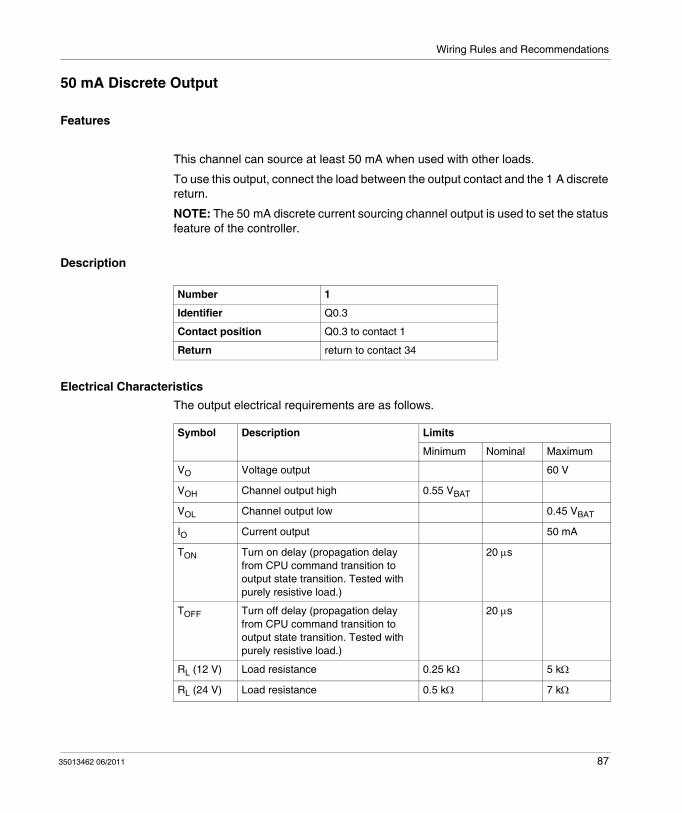
Wiring Rules and Recommendations
50 mA Discrete Output
Features
This channel can source at least 50 mA when used with other loads.
To use this output, connect the load between the output contact and the 1 A discrete return.
NOTE: The 50 mA discrete current sourcing channel output is used to set the status feature of the controller.
Description
Electrical CharacteristicsThe output electrical requirements are as follows.
Number 1
Identifier Q0.3
Contact position Q0.3 to contact 1
Return return to contact 34
Symbol Description Limits
Minimum Nominal Maximum
VO Voltage output 60 V
VOH Channel output high 0.55 VBAT
VOL Channel output low 0.45 VBAT
IO Current output 50 mA
TON Turn on delay (propagation delay from CPU command transition to output state transition. Tested with purely resistive load.)
20 μs
TOFF Turn off delay (propagation delay from CPU command transition to output state transition. Tested with purely resistive load.)
20 μs
RL (12 V) Load resistance 0.25 kΩ 5 kΩ
RL (24 V) Load resistance 0.5 kΩ 7 kΩ
35013462 06/2011 87

Wiring Rules and Recommendations
Connection Diagram
ProtectionThe 50 mA discrete current sourcing channel output can detect load dumps and short circuits between +battery and ground and can provide protection.
Channel FaultIn case of short to ground fault, the channel is turned off within 20 ms of a valid fault feedback signal.
A new connection attempt will occur every 77 ms. Trying the output connection earlier than specified may damage the channel.
Load Dump ConditionsIgnoring the short circuit fault before a load dump allows to check that no erroneous short faults are flagged, if the fault line goes active before the load dump interrupt sets the output as disabled.
The short circuit fault is ignored.
88 35013462 06/2011

Wiring Rules and Recommendations
300 mA Discrete Outputs
FeaturesThe 300 mA current sinking discrete channels are available for 12 V and 24 V systems.
NOTE: 6 of the 300 mA outputs have a 85 V protection limit and 8 have a 150 V protection limit.
NOTE: Contact Q0.18 works with a reverse logic. It is activated by default.
NOTE: Contacts Q0.10...Q0.17 are not available for 24 V systems.
Description
Electrical CharacteristicsThe output electrical requirements are as follows.
Number 14
Identifier Q0.5 to Q0.18
Contact position Q0.5 to contact 31Q0.6 to contact 12Q0.7 to contact 13Q0.8 to contact 43Q0.9 to contact 42Q0.10 to contact 66Q0.11 to contact 65Q0.12 to contact 64Q0.13 to contact 63Q0.14 to contact 67Q0.15 to contact 54Q0.16 to contact 62Q0.17 to contact 53Q0.18 to contact 23
Symbol Description Limits
Minimum Nominal Maximum
IL Leakage current 24 VBAT 1 mA
IO Current output 300 mA
35013462 06/2011 89

Wiring Rules and Recommendations
Connection Diagram
ProtectionThe 300 mA current sinking discrete channel output can detect load dumps and short circuits between +battery and ground and can provide protection.
Channel Fault The channels have different fault condition characteristics.
Fault conditions for channels Q0.5, Q0.6, Q0.7 and Q0.18
In case of short to battery fault, the channel is turned off within 100 ms of a valid fault feedback signal.
A new connection attempt will occur every 1.5 s. Trying the output connection earlier than specified may damage the channel.
The feedback signal for this channel is valid 100 ms after the channel state changes.
RLSS Steady state load resistance (Resistance for incandescent lamps or other dynamic devices are typically 0.1 RLSS for up to 15 ms. Under these conditions, the channel pulse ON and OFF or current limit until the load reaches the RLSS range.
0.05 kΩ 0.1 kΩ 12 kΩ
TON Turn on delay (propagation delay from CPU command transition to output state transition. Tested with purely resistive load.)
20 μs
TOFF Turn off Delay (propagation delay from CPU command transition to output state transition. Tested with purely resistive load.)
20 μs
VOL Flash frequency 3 Hz
90 35013462 06/2011
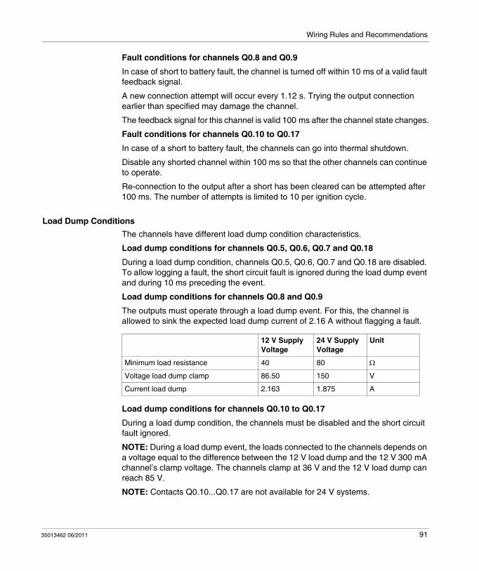
Wiring Rules and Recommendations
Fault conditions for channels Q0.8 and Q0.9
In case of short to battery fault, the channel is turned off within 10 ms of a valid fault feedback signal.
A new connection attempt will occur every 1.12 s. Trying the output connection earlier than specified may damage the channel.
The feedback signal for this channel is valid 100 ms after the channel state changes.
Fault conditions for channels Q0.10 to Q0.17
In case of a short to battery fault, the channels can go into thermal shutdown.
Disable any shorted channel within 100 ms so that the other channels can continue to operate.
Re-connection to the output after a short has been cleared can be attempted after 100 ms. The number of attempts is limited to 10 per ignition cycle.
Load Dump ConditionsThe channels have different load dump condition characteristics.
Load dump conditions for channels Q0.5, Q0.6, Q0.7 and Q0.18
During a load dump condition, channels Q0.5, Q0.6, Q0.7 and Q0.18 are disabled. To allow logging a fault, the short circuit fault is ignored during the load dump event and during 10 ms preceding the event.
Load dump conditions for channels Q0.8 and Q0.9
The outputs must operate through a load dump event. For this, the channel is allowed to sink the expected load dump current of 2.16 A without flagging a fault.
Load dump conditions for channels Q0.10 to Q0.17
During a load dump condition, the channels must be disabled and the short circuit fault ignored.
NOTE: During a load dump event, the loads connected to the channels depends on a voltage equal to the difference between the 12 V load dump and the 12 V 300 mA channel’s clamp voltage. The channels clamp at 36 V and the 12 V load dump can reach 85 V.
NOTE: Contacts Q0.10...Q0.17 are not available for 24 V systems.
12 V Supply Voltage
24 V Supply Voltage
Unit
Minimum load resistance 40 80 Ω
Voltage load dump clamp 86.50 150 V
Current load dump 2.163 1.875 A
35013462 06/2011 91
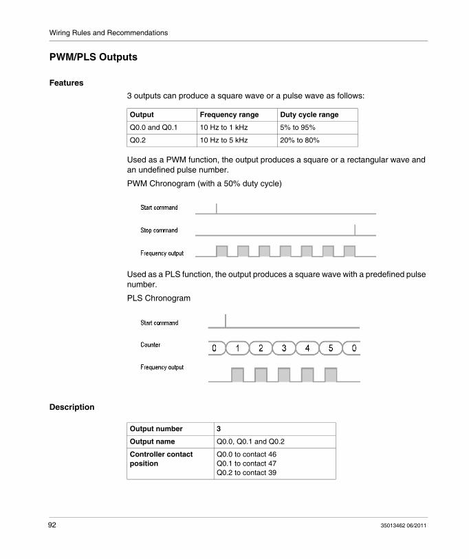
Wiring Rules and Recommendations
PWM/PLS Outputs
Features3 outputs can produce a square wave or a pulse wave as follows:
Used as a PWM function, the output produces a square or a rectangular wave and an undefined pulse number.
PWM Chronogram (with a 50% duty cycle)
Used as a PLS function, the output produces a square wave with a predefined pulse number.
PLS Chronogram
Description
Output Frequency range Duty cycle range
Q0.0 and Q0.1 10 Hz to 1 kHz 5% to 95%
Q0.2 10 Hz to 5 kHz 20% to 80%
Output number 3
Output name Q0.0, Q0.1 and Q0.2
Controller contact position
Q0.0 to contact 46Q0.1 to contact 47Q0.2 to contact 39
92 35013462 06/2011

Wiring Rules and Recommendations
Electrical Characteristics for Q0.0 and Q0.1The output electrical requirements for Q0.0 and Q0.1 are as follows.
Electrical Characteristics for Q0.2The output electrical requirements for Q0.2 are as follows.
Symbol Description Limits
Minimum Nominal Maximum
Frequency accuracy 1 %
Duty cycle accuracy 2 %*
VOL Channel output low (OFF) 1.2 V
VOH Channel output high (ON) 4.3 V 4.6 V 4.9 V
ISI Channel sinking current 35 mA
DO Channel output duty cycle 5 % 95 %
fo Channel output frequency 10 Hz 1000 Hz
RL (12 V) Load resistance 0.3 kΩ
RL (24 V) Load resistance 0.7 kΩ
*maximum of the full scale
Symbol Description Limits
Minimum Nominal Maximum
Frequency accuracy 1 %
Duty cycle accuracy signal inferior to 1 KHz 2 %*
signal between 1 KHz and 3 KHz 4 %*
signal between 3 KHz and 5 KHz 25 %*
VOL Channel output low (OFF) 1.2 V
VOH Channel output high (ON) 12.3 V 12.6 V 12.9 V
fO Channel output frequency 10 Hz 5000 Hz
ISI Channel sinking current 40 mA
DO Channel output duty cycle 20 % 80 %
RL (12 V) Load resistance 0.3 kΩ
RL (24 V) Load resistance 0.6 kΩ
*maximum of the full scale
35013462 06/2011 93

Wiring Rules and Recommendations
Connection Diagram
Channel FaultFor Q0.0 and Q0.1
In case of a short to battery condition, the channel is disabled within 4 ms of valid fault feedback signal. The outputs can be tried again after 10 ms.
Under a short to ground condition, the channel is turned off.
A new connection attempt can occur every 10 ms provided that the driver has been turned off after 4 ms.Trying the output connection earlier than specified may damage the channel.
The feedback signal for this driver is valid 100 s after a change in the driver output state has been required.
For Q0.2
In case of a short to ground fault, the channel is turned off.
A new connection attempt can occur every 65.6 ms. Trying the output connection earlier than specified may damage the channel.
94 35013462 06/2011
35013462 06/2011
4
Twido Extreme Programmable ControllerController Operation35013462 06/2011
Controller Operation
IntroductionThis chapter provides information about the controller operating modes.
What’s in this Chapter?This chapter contains the following topics:
Topic Page
Cyclic Scan 96
Periodic Scan 98
Checking Scan Time 101
Operating Modes 102
Dealing with Power Cuts and Power Restoration 104
Dealing with a Warm Restart 106
Dealing with a Cold Start 108
Initialization of objects 110
95

Controller Operation
Cyclic Scan
IntroductionCyclic scanning involves linking controller cycles together one after the other. After having performed an output update (task cycle third phase), the system executes its own tasks and immediately triggers another task cycle.
NOTE: The controller watchdog timer monitors the scan time of the user program. The scan time must not exceed 500 ms otherwise a fault appears and causes the controller to stop immediately in HALT mode. Outputs in this mode are forced to their default fallback state.
OperationThe following diagram shows the running phases of the cyclical scan time.
Cycle Phases Description The following table describes the phases of a cycle.
Address Phase Description
I.P. Internal processing
The system implicitly monitors the controller (managing system bits and words, updating current timer values, updating status lights, detecting RUN/STOP switches, etc.) and processes requests from TwidoSuite (modifications and animation).
I, IW Acquiring input
Writing to the memory the status of discrete and application specific module inputs.
- Program processing
Running the application program written by the user.
Q, QW Updating outputs
Writing output bits or words associated with discrete and application specific modules.
96 35013462 06/2011

Controller Operation
Operating ModesController in RUN mode
in RUN mode, the processor carries out:
Internal processingAcquiring inputs Processing the application programUpdating outputs
Controller in STOP mode
In STOP mode, the processor carries out:
Internal processingAcquiring inputs
Illustration The following illustration shows the operating cycles.
Check CycleThe check cycle is performed by the watchdog.
35013462 06/2011 97

Controller Operation
Periodic Scan
IntroductionIn this operating mode, acquiring inputs, processing the application program and updating outputs are done periodically according to the time defined at configuration (from 2-150 ms).
When the controller starts to scan, a timer starts to count down, the value of this timer is initialized at the period defined at configuration. The controller scan must end before the timer has finished and launches a new scan.
OperationThe following diagram shows the running phases of the periodic scan time.
Description of Operating PhasesThe table below describes the operating phases.
Address Phase Description
I.P. Internal processing
The system implicitly monitors the controller (managing system bits and words, updating current timer values, updating status lights, detecting RUN/STOP switches, etc.) and processes requests from TwidoSuite (modifications and animation).
I, IW Acquiring inputs Writing to the memory the status of discrete and application specific module inputs.
- Processing program
Running the application program written by the user.
Q, QW Updating outputs Writing output bits or words associated with discrete and application specific modules.
98 35013462 06/2011

Controller Operation
Operating ModesController in RUN mode
In RUN mode, the processor carries out:
Internal processingAcquiring inputsProcessing the application programUpdating outputs
If the period has not finished, the processor completes the operating cycle until the end of the internal processing period.
If the operating time is longer than the time allocated to the period, the controller sets the system bit S19 to 1 to indicate that the period has been exceeded.The process continues until the end. However, it must not exceed the watchdog time limit.
The next scan starts after writing the outputs of the scan in progress.
Controller in STOP mode
In STOP mode, the processor carries out:
Internal processingAcquiring inputs
35013462 06/2011 99

Controller Operation
Illustration The following illustration shows the operating cycles.
Check CycleTwo checks are carried out:
Period overflowWatchdog
100 35013462 06/2011

Controller Operation
Checking Scan Time
GeneralThe task cycle is monitored by a watchdog timer called Tmax (maximum duration of the task cycle). It indicates the application errors (infinite loops for example) and gives a maximal duration for output refreshing.
Software WatchDog (Periodic or Cyclic Operation)In periodic or cyclic operation, triggering the watchdog causes a software error. The application goes into a HALT state and sets the system bit S11 to 1. Relaunching the task requires a connection to TwidoSuite in order to:
analyze the cause of the error,modify the application to correct the error,reset the program to RUN.
NOTE: The HALT state occurs when the application immediately stops because of an application software error such as a scan overrun. The data retains the current values, which allows for an analysis of the cause of the error. The program stops on the instruction in progress. Communication with the controller is set.
Check on Periodic OperationIn periodic operation, an additional check is used to detect the period that is exceeded:
S19 indicates that the period has been exceeded. It is set to:1 by the system when the scan time is greater that the task period,0 by the user.
SW0 contains the period value (0-150 ms). It is:Initialized when starting from a cold start by the value selected on the configuration,Able to be modified by the user.
Using Master Task Running TimeThe following system words are used for information on the controller scan cycle time:
SW11 initializes to the maximum watchdog time (10 to 500 ms).SW30 contains the execution time for the last controller scan cycle.SW31 contains the execution time for the longest controller scan cycle since the last cold start.SW32 contains the execution time for the shortest controller scan cycle since the last cold start.
NOTE: The information can also be accessed from the configuration editor.
35013462 06/2011 101

Controller Operation
Operating Modes
IntroductionTwidoSuite is used to take into account the 3 main operating mode groups:
CheckingRunning or productionStopping
Starting through GrafcetThese different operating modes can be obtained either starting from or using the following Grafcet methods:
Initializing GrafcetPresetting stepsMaintaining a situationFreezing charts
Preliminary processing and use of system bits ensure effective operating mode management without complicating and overburdening the user program.
Grafcet System BitsUse of bits S21, S22 and S23 is reserved for preliminary processing only. These bits are automatically reset by the system. They must be written by Set Instruction S only.
The following table provides Grafcet-related system bits:
Bit Function Description
S21 GRAFCET initialization Normally set to 0, it is set to 1 by:A cold-start: S0=1.The user: in the pre-processing program part only, using a Set Instruction S S21 or a set coil -(S)- S21.
Consequences:Deactivation of all active steps.Activation of all initial steps.
S22 GRAFCET RESET Normally set to 0, it can only be set to 1 by the program in pre-processing.Consequences:
Deactivation of all active steps.Scanning of sequential processing stopped.
102 35013462 06/2011

Controller Operation
S23 Preset and freeze GRAFCET
Normally set to 0, it can only be set to 1 by the program in pre-processing.
Prepositioning by setting S22 to 1.Preposition the steps to be activated by a series of S Xi instructions.Enable prepositioning by setting S23 to 1.
Freezing a situation:In initial situation: by maintaining S21 at 1 by program.In an "empty" situation: by maintaining S22 at 1 by program.In a situation determined by maintaining S23 at 1.
Bit Function Description
35013462 06/2011 103

Controller Operation
Dealing with Power Cuts and Power Restoration
Illustration The following diagram shows the various power restarts detected by the system. The program notices when the power cut lasts less than the power supply filtering time (about 10 ms for an alternating current supply or 1 ms for a direct current supply), it runs normally
104 35013462 06/2011
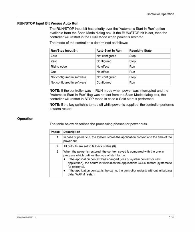
Controller Operation
RUN/STOP Input Bit Versus Auto RunThe RUN/STOP input bit has priority over the ‘Automatic Start in Run’ option available from the Scan Mode dialog box. If the RUN/STOP bit is set, then the controller will restart in the RUN Mode when power is restored.
The mode of the controller is determined as follows:
NOTE: If the controller was in RUN mode when power was interrupted and the "Automatic Start in Run" flag was not set from the Scan Mode dialog box, the controller will restart in STOP mode in case a Cold start is performed.
NOTE: If the key switch is turned off while power is supplied, the controller performs a warm restart.
OperationThe table below describes the processing phases for power cuts.
Run/Stop Input Bit Auto Start in Run Resulting State
Zero Not configured Stop
Zero Configured Stop
Rising edge No effect Run
One No effect Run
Not configured in software Not configured Stop
Not configured in software Configured Run
Phase Description
1 In case of power cut, the system stores the application context and the time of the power cut.
2 All outputs are set to fallback status (0).
3 When the power is restored, the context saved is compared with the one in progress which defines the type of start to run:
If the application context has changed (loss of system context or new application), the controller initializes the application: COLD restart (systematic for extreme).If the application context is the same, the controller restarts without initializing data: WARM restart.
35013462 06/2011 105
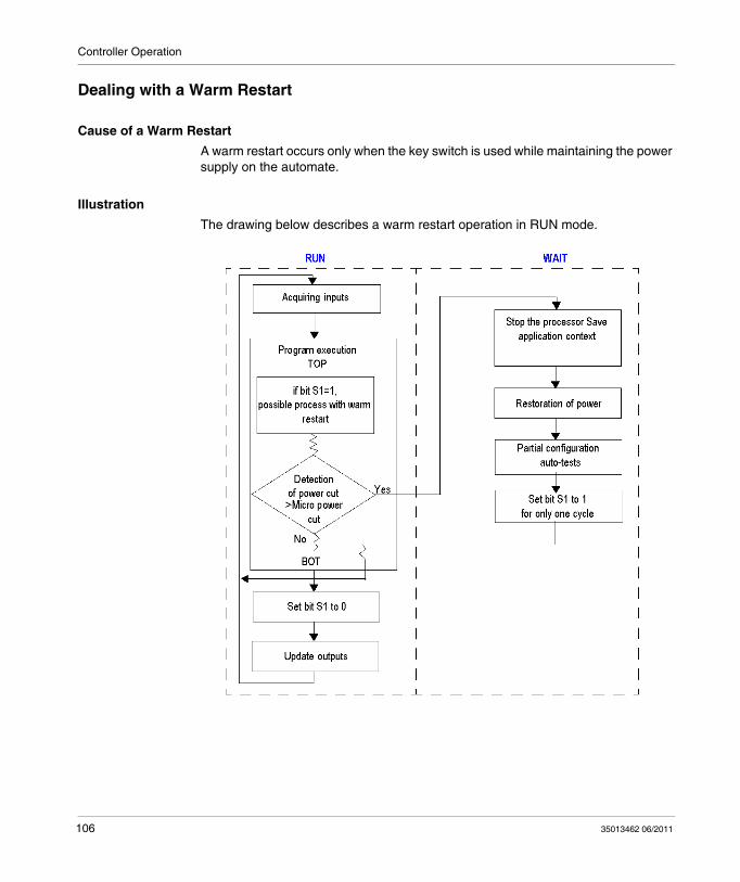
Controller Operation
Dealing with a Warm Restart
Cause of a Warm RestartA warm restart occurs only when the key switch is used while maintaining the power supply on the automate.
Illustration The drawing below describes a warm restart operation in RUN mode.
106 35013462 06/2011

Controller Operation
Restart of the Program ExecutionThe table below describes the restart phases for running a program after a warm restart.
Processing of a Warm Start In the case of a warm start, if a particular application process is required, bit S1 must be tested at the start of the task cycle, and the corresponding program called up.
Outputs after Power FailureOnce a power outage is detected, the outputs are set to (default) fallback status (0).
When the power is restored, the outputs are in the last state they were until they are updated again by the task.
Phase Description
1 The program execution resumes from the same element where it was prior to the power cut, without updating the outputs.Note: Only the same element from the user code is restarted. The system code (for example, the updating of outputs) is not restarted.
2 At the end of the restart cycle, the system: Unreserves the application if it was reserved.Reinitializes the messages.
3 The system carries out a restart cycle in which it: Relaunches the task with bits S1 (warm-start indicator) and S13 (first cycle in RUN) set to 1.Resets bits S1 and S13 to 0 at the end of the first task cycle.
35013462 06/2011 107

Controller Operation
Dealing with a Cold Start
Cause of a Cold StartA cold-start can occur:
When loading a new application into RAMWhen power is restored with loss of application contextWhen system bit S0 is set to state 1 by the programFrom the Operator Display when the controller is in STOP mode
Illustration The diagram below describes a cold restart operation in RUN mode.
108 35013462 06/2011

Controller Operation
OperationThe table below describes the restart phases for running a program after a cold restart.
Processing of a Cold StartIn the event of a cold-start, if a particular application process is required, bit S0 (which is at 1) must be tested during the first cycle of the task.
Outputs after Power FailureOnce a power outage is detected, outputs are set to (default) fallback status (0).
When power is restored, outputs are at zero until they are updated again by the task.
Phase Description
1 At start up, the controller is in RUN.At a cold restart after a stop due to an error, the system forces a cold restart.The program execution restarts at the beginning of the cycle.
2 The system: Resets internal bits and words and the I/O images to 0.Initializes system bits and words.Initializes function blocks from configuration data.
3 For this first restart cycle, the system: Relaunches the task with bits S0 (cold-start indicator) and S13 (first cycle in RUN) set to 1.Resets bits S0 and S13 to 0 at the end of this first task cycle.Sets bits S31 and S38 (event control indicators) to their initial state 1.Resets bits S39 (event control indicator) and word SW48 (counts all events executed except periodic events).
35013462 06/2011 109

Controller Operation
Initialization of objects
IntroductionThe controllers can be initialized by TwidoSuite by setting system bits %S0 (a cold restart) and %S1 (a warm restart).
Cold Start InitializationFor a cold start initialization, system bit %S0 must be set to 1.
Initialization of objects (identical to cold start) on power-up using S0 and S1To initialize objects on power-up, system bit %S1 and %S0 must be set to 1.
Ladder Language
The following example shows how to program a warm restart object initialization using system bits.
Instruction List Language
LD %S1
JMPC %L1
%L1:
LD %S1
ST %S0
END
110 35013462 06/2011

Controller Operation
LD %S1 If %S1 = 1 (warm restart), set %S0 to 1 to initialize the controller.
ST S These two bits are reset to 0 by the system at the end of the following scan.
NOTE: Do not set %S0 to 1 for more than one controller scan.
35013462 06/2011 111

Controller Operation
112 35013462 06/2011

Twido Extreme Programmable Controller
35013462 06/2011
Appendices
35013462 06/2011 113

114 35013462 06/2011

35013462 06/2011
A
Twido Extreme Programmable ControllerAppendices35013462 06/2011
Appendices
IntroductionThis chapter provides an example of application and the associated functions.
What’s in this Chapter?This chapter contains the following topics:
Topic Page
Application Example for Mobile Vehicles 116
Single Axis Lever 118
Glossary of Symbols 123
Agency Requirements 124
115
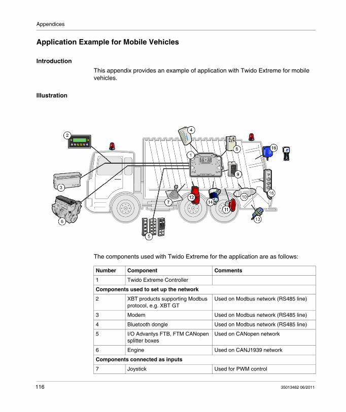
Appendices
Application Example for Mobile Vehicles
IntroductionThis appendix provides an example of application with Twido Extreme for mobile vehicles.
Illustration
The components used with Twido Extreme for the application are as follows:
Number Component Comments
1 Twido Extreme Controller
Components used to set up the network
2 XBT products supporting Modbus protocol, e.g. XBT GT
Used on Modbus network (RS485 line)
3 Modem Used on Modbus network (RS485 line)
4 Bluetooth dongle Used on Modbus network (RS485 line)
5 I/O Advantys FTB, FTM CANopen splitter boxes
Used on CANopen network
6 Engine Used on CANJ1939 network
Components connected as inputs
7 Joystick Used for PWM control
116 35013462 06/2011

Appendices
8 Normal relays
9 Static Relays
10 Hydraulic valve Used for PWM control
Components connected as outputs
1112
Preventa module (11) with an emergency stop button (12)
Handles security with the emergency stop button
13 Proximity sensor
14 Pressure sensor
15 Push button station
16 RFID sensor and the associated command
Number Component Comments
35013462 06/2011 117
Appendices
Single Axis Lever
IntroductionThis appendix gives the characteristics, operations and performance of the single axis lever you can connect to the PWM input.
DescriptionThis is a single-axis spring-return-to-center model with a tactile detent at +/-17.5° deflection.The narrow housing design allows for side by side mounting of the joysticks for multiple control functions.
The joystick base utilizes a specific technology that allows for stable operation over the full deflection range, as well as a no-hysteresis line a output signal that is proportional to the operator input.
This joystick is designed to withstand the temperatures, shock, vibration and EMI/RFI conditions normally encountered in mobile equipment applications. In tests up to 6 million cycles, this joystick has shown no signs of bearing or boot wear, and no reduction of electrical performance.
118 35013462 06/2011

Appendices
DimensionsThe single axis lever has the following dimensions.
DANGERHAZARDOUS VOLTAGE
Disconnect power before wiring or assembling/disassembling the equipment
Failure to follow these instructions will result in death or serious injury.
35013462 06/2011 119

Appendices
Performances
OperationThe joysticks operate as low level control signal output devices only. With a supply voltage of 9...32 VDC to the connector of the joystick, a PWM output control signal will be available to act as the input to a valve amplifier/controller.
This PWM signal from the joystick is at 50 % duty cycle when the joystick is centered. When the joystick is deflected off-center, the PWM duty cycle output changes proportionally within the range of +/-40 %.
This joystick PWM output cannot be used to directly control a proportional valve.
An additional controller is required to convert the joystick PWM output signal to a stable output current which can drive the proportional coils. Duty cycles above and below the suggested range of 50 % +/-40 % are used for system diagnostics.
FeaturesThe single axis lever has the following features:
Single-function implement controlPulse width modulated (PWM) output to the controller.Tactile indicators for float (detent) return-to-dig and bucket leveling functions.Can be ganged in sets of two or three units for lift, tilt, and auxiliary control.Mounting in Armrest, typically.Two units can be used in place of one two-axis joystick.Advanced ASIC technology for reliability and accuracy.Reliable operation in extreme temperature conditions from –40° C +85° C.Rugged diecast metal housing.
120 35013462 06/2011
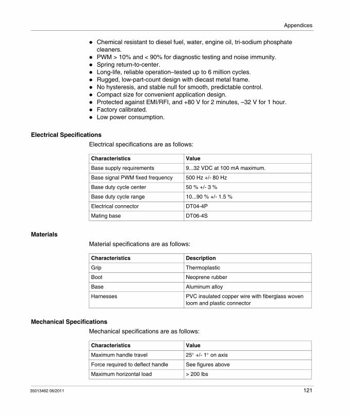
Appendices
Chemical resistant to diesel fuel, water, engine oil, tri-sodium phosphate cleaners.PWM > 10% and < 90% for diagnostic testing and noise immunity.Spring return-to-center.Long-life, reliable operation–tested up to 6 million cycles.Rugged, low-part-count design with diecast metal frame.No hysteresis, and stable null for smooth, predictable control.Compact size for convenient application design.Protected against EMI/RFI, and +80 V for 2 minutes, –32 V for 1 hour.Factory calibrated.Low power consumption.
Electrical SpecificationsElectrical specifications are as follows:
MaterialsMaterial specifications are as follows:
Mechanical SpecificationsMechanical specifications are as follows:
Characteristics Value
Base supply requirements 9...32 VDC at 100 mA maximum.
Base signal PWM fixed frequency 500 Hz +/- 80 Hz
Base duty cycle center 50 % +/- 3 %
Base duty cycle range 10...90 % +/- 1.5 %
Electrical connector DT04-4P
Mating base DT06-4S
Characteristics Description
Grip Thermoplastic
Boot Neoprene rubber
Base Aluminum alloy
Harnesses PVC insulated copper wire with fiberglass woven loom and plastic connector
Characteristics Value
Maximum handle travel 25° +/- 1° on axis
Force required to deflect handle See figures above
Maximum horizontal load > 200 lbs
35013462 06/2011 121

Appendices
Environmental SpecificationsEnvironmental specifications are as follows:
Characteristics Value
Operating temperature - 40° C...+ 85° C (- 40° F...185° F)
Storage temperature - 40° C...+ 85° C (- 40° F...185° F)
EMI/RFI (SAE J1113-21 level 6) 100 V/M, 15 KHz...1 GHz
Sealing +/- 0.35 bar (5 psi); 0.1 bar (1.5 psi) water spray
Housing classifications IP 67
Vibration 9.8 G random three axis, 8 grms (24 Hz...2 KHz)
Short circuit protection All inputs and outputs are protected from short to battery and ground.
122 35013462 06/2011
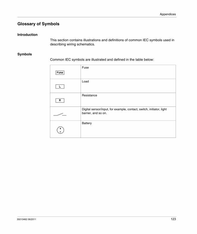
Appendices
Glossary of Symbols
IntroductionThis section contains illustrations and definitions of common IEC symbols used in describing wiring schematics.
SymbolsCommon IEC symbols are illustrated and defined in the table below:
Fuse
Load
Resistance
Digital sensor/input, for example, contact, switch, initiator, light barrier, and so on.
Battery
35013462 06/2011 123
Appendices
Agency Requirements
IntroductionThis section provides agency standards for this product.
StandardsTwido Extreme controller complies with the main national and international standards concerning electronic industrial control devices.
The following are specific controller requirements:
European "Automotive" Directive 2004/104/CE and Rules ECE N°10 (ECE R10) (e and E marks)European "Low Voltage" Directive 73/23/CEE (CE mark):Standards: EN(IEC) 61131-2European "EMC" Directive 89/336/CEE (CE mark).Standards:EN(IEC) 61131-2, EN(IEC) 61000-6-2, EN(IEC) 61000-6-4Certification UL 508Certification CSA C22.2 N°142
124 35013462 06/2011

Twido Extreme Programmable ControllerGlossary35013462 06/2011
Glossary
A
analog inputA module containing circuits that enable analog DC (Direct Current) input signals to be converted into digital values that can be handled by the processor. This implies that the analog inputs are generally direct values — in other words: a value in the data table is a direct reflection of the analog signal value.
analog outputA module containing circuits that transmit an analog DC (Direct Current) input signal proportional to a digital input value to the processor module. This implies that the analog outputs are generally direct values — in other words: a value in the data table directly governs the analog signal value.
C
CANController Area Network. The CAN protocol (ISO 11898) for serial bus networks is designed to connect a series of intelligent devices (from different manufacturers) together into intelligent systems for real-time industrial applications. Multi-master CAN systems provide a high level of data integrity, by implementing message broadcast mechanisms and a strict error checking procedure. Initially developed for the automotive industry, the CAN protocol is now used in a wide range of automation environments.
CANJ1939A protocol for automobile applications allowing communication with engines.
35013462 06/2011 125

Glossary
CANopenAn open standard industrial protocol used on the internal communication bus. This protocol can be used to connect any CANopen standard-compliant device to the island bus
D
discrete input/outputAnother expression used is digital input/output. Designates an input or an output featuring an individual circuit connection to the module corresponding directly to a bit or word of the data table storing the value of the signal on this I/O circuit. A digital I/O gives the control logic discrete access to I/O values
DTPData Protocol Transfer. When the DPT signal is used, the controller sets the connection according to the communication port configuration defined in the application (see also Programming Protocol).
E
ECUElectronic Control Unit. An embedded system used to control one or several electrical subsystems in the vehicle.
F
fast countingA special function available as a single up counter and single down counter.
These functions allow counting pulses up or down (rising edges) on a digital I/O.
Extreme controllers are equipped with 1 fast counter.
126 35013462 06/2011

Glossary
I
IECInternational Electrotechnical Commission. Commission officially founded in 1906 and devoted to the advancement of theory and practice in the following sciences: electrical engineering, electronic engineering, information technology and computer engineering. The IEC 1131 standard covers industrial automation equipment.
IEEEInstitute of Electrical and Electronics Engineers, Inc. An international association for the standardization and evaluation of compliance in all areas of electro-technology, including electricity and electronics.
input filteringA special function that rejects input noises. This function is useful for eliminating input noises and chatter in limit switches. All inputs provide a level of input filtering using the hardware. Additional filtering using the software is also configurable through TwidoSuite.
L
latching inputA special function used to memorize pulses with a duration less than the controller scan time. When a pulse is shorter than one scan and has a value greater than or equal to 100 μs, the controller latches the pulse, which is then updated in the next scan.
M
master/slave modelIn a network using a master/slave model, the direction of control is always from the master to slave devices.
Modbus master modeA communication mode that allows the controller to initiate a Modbus query transmission, with a response expected from a Modbus slave.
35013462 06/2011 127

Glossary
Modbus slave modeA communication mode that allows the controller to respond to Modbus queries from a Modbus master and is the default communications mode if no communication is configured.
O
operator display moduleAn optional module that can be attached to the controller to display program information.
P
PDO, objectProcess Data Object. On networks based on CAN technology, PDOs (Process Data Objects) are transmitted as broadcast messages without confirmation or are sent from a producer device to a consumer device. The transmitted PDO (TxPDO) from the producer device has a specific identifier corresponding to the PDO (RxPDO) received from client devices.
PLCProgrammable Logic Controller. Programmable Logic Controller. The PLC is the kernel of the industrial manufacturing process. A controller allows to automate a process compared to a relay control system. The PLCs are computers designed to survive under harsh conditions of an industrial environment.
PLSPulse Generator Output. A special user-defined function block that generates a signal on output Q0.0 or Q0.1. This signal has a variable period but has a constant duty cycle, or on to off ratio of 50% of the period.
programming protocolThe controller uses the Modbus protocol (slave address 1, 19 200 bauds, 8 data bits, no parity, 1 stop bit) to communicate when no DTP signal is detected (see also DPT).
128 35013462 06/2011

Glossary
PWMPulse Width Modulation. A special user-defined function block that generates a signal on output Q0.0 or Q0.1. This signal has a constant period with the possibility of varying the duty cycle, or on to off ratio.
R
RTCReal Time Clock. A serially readable/writable device that maintains the current time and date without the system CPU running.
S
SDO, objectService Data Object. On CAN networks, the fieldbus master (CANopen) uses SDO messages for (read/write) access to the network node object dictionaries.
Status outputA special function assigned to Q0.3. At power up, the controller status output is set to 1if the controller is in RUN mode without errors.This function can be used in circuits external to the controller to control, for example, the power supply to the output devices.
35013462 06/2011 129

Glossary
130 35013462 06/2011

Twido Extreme Programmable ControllerIndex35013462 06/2011
CBA
IndexAAccessories, 19
Mounting kit, 21Agency requirements, 124Analog functions, 15Analog input or PWM, 67Analog inputs, 67Application update software, 15ASCII, 14
BBattery, 12
CCalendar, 15CAN network, 59Checking scan time, 101Cold start, 108Communication
Architecture, 23CANJ1939, 26CANopen, 24Modbus, 28Overview, 22
Communication with a PCusing a modem, 29using Bluetooth, 29using Ethernet, 30
Controller status output , 87
35013462 06/2011
CounterFast counter, 63
DDedicated functions , 14Determining the state of Run/Stop input, 62Digital I/O assignment
PLS, 64PWM, 64Run/Stop input, 62
Discrete inputs, 66Discrete inputs programmable states, 66, 84Double-word
Fast counter, 63PLS, 64
EEnvironment operating conditions, 37Ethernet connection
Power supply wiring, 30RS485 serial line wiring, 31
Execution time, 14
FFast counter, 63
Double-word, 63Single-word, 63
Filtering, 14, 66, 84Forcing, 66, 84
131

Index
GGrafcet methods, 102
HHow to connect the battery, 39How to connect the power supply, 40How to mount a Twido Extreme controller, 43
IIEC symbols, 123Initialization of objects, 110Input/output extension, 12, 15Inputs
Source and sink, 66Inputs and outputs
Contacts location, 50
LLatching, 66, 84
MMain Features, 14Memory capacity, 14Modbus, 14Modbus link, 59Motion functions, 15Mounting
Battery connection, 39Bolt Torque specification, 43Fuse specifications, 38Instructions, 38Power supply connection, 40
NNetwork wiring, 59
OOperating modes, 102
132
Operator display, 15Options
Actuators, 16Adapters, 17Cables, 17Dialog display, 18Relays, 16Sensors, 16
Outputs processing states, 84
PPLS, 64
Double-word, 64Single-word, 64
Power cut, 104Power restoration, 104Power supply, 12
Controller requirements, 34Reverse voltage protection, 35Sensors requirements, 35Voltage in operating mode, 34Voltage in standby mode, 34
Programming port, 15Programming protocol, 28Pulse generator output, 64Pulse Width Modulation, 64PWM, 64PWM input, 67
RRS485 Modbus connection, 58Run/Stop bit, 105Run/Stop input, 62
SS21, 102S22, 102S23, 103Scan time, 101Scanning, 14
Cyclic, 96
35013462 06/2011

Index
Scanning Periodic, 98
Single counterDown, 63Up, 63
Single-wordFast counter, 63PLS, 64
Sink inputs, 66Software watchdog, 101Source inputs, 66Special functions
Controller status output, 87Fast counter, 63Latching input, 66, 84PLS, 64PWM, 64Run/Stop input, 62
Special inputs, 15Special outputs, 15Standards, 124Standby mode, 15Symbols, 123
TTask cycle, 101Terminal block, 15Turning the controller ON and OFF, 62Twido Extreme Controller
Description, 12Dimensions, 36Features, 14Parts description, 12
WWarm restart, 106Wiring
Network, 59Rules, 47
Wiring using EthernetPower supply , 30RS485Serial line , 31
Wiring using RS485 Modbus connection, 58
35013462 06/2011
133
Index
134 35013462 06/2011