Embed Size (px)
Citation preview
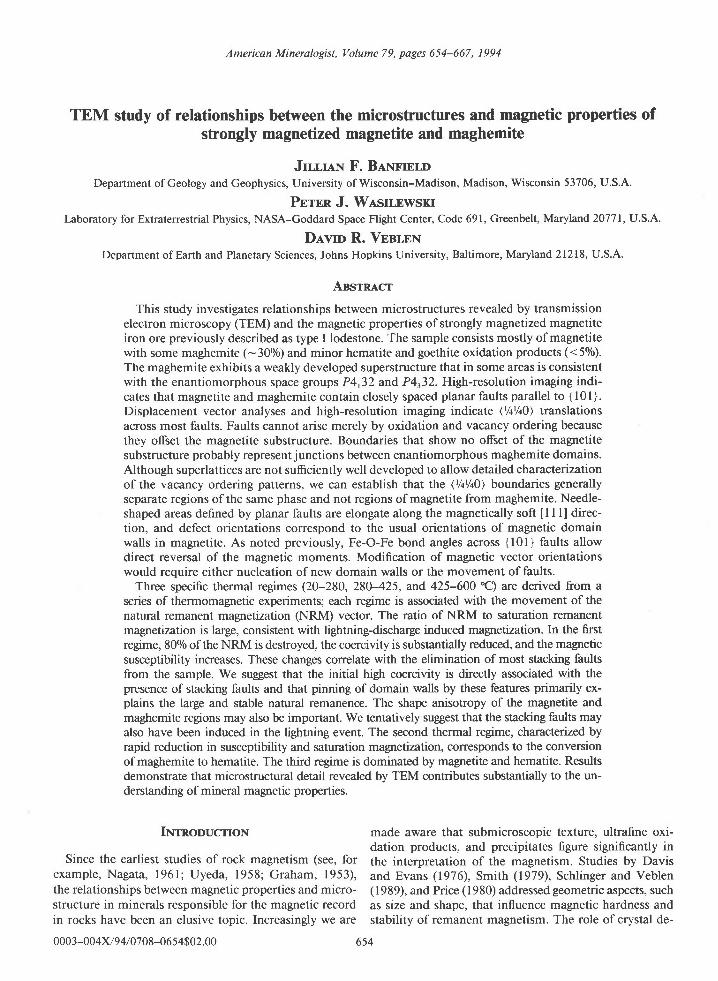
American Mineralogist, Volume 79, pages 654-667, 1994
TEM study of relationships between the microstructures and magnetic properties ofstrongly magnetized magnetite and maghemite
Jrr.r.HN F. Barvrrnr.nDepartment of Geology and Geophysics, University of Wisconsin-Madison, Madison, Wisconsin 53706, U.S.A.
Prrrn J. W.lsrr,EwsKrLaboratory for Extraterrestrial Physics, NASA-Goddard Space Flight Center, Code 691, Greenbelt, Maryland 20771, U.S.A.
Dlvro R. VenlrxDepartment of Earth and Planetary Sciences, Johns Hopkins University, Baltimore, Maryland 21218, U.S.A.
Ansrru,cr
This study investigates relationships between microstructures revealed by transmissionelectron microscopy (TEM) and the magnetic properties of strongly magnetized magnetiteiron ore previously described as type I lodestone. The sample consists mostly of magnetitewith some maghemite (-3070) and minor hematite and goethite oxidation products (<50/o).The maghemite exhibits a weakly developed superstructure that in some areas is consistentwith the enantiomorphous space groups P4r32 and P\32. High-resolution imaging indi-cates that magnetite and maghemite contain closely spaced planar faults parallel to { l0l }.Displacement vector analyses and high-resolution imaging indicate (Y+Yr0) translationsacross most faults. Faults cannot arise merely by oxidation and vacancy ordering becausethey offset the magnetite substructure. Boundaries that show no offset of the magnetitesubstructure probably represent junctions between enantiomorphous maghemite domains.Although superlattices are not sufficiently well developed to allow detailed characterizationof the vacancy ordering patterns, we can establish that the (Yr%0) boundaries generallyseparate regions of the same phase and not regions of magnetite from maghemite. Needle-shaped areas defined by planar faults are elongate along the magnetically soft I I l] direc-tion, and defect orientations correspond to the usual orientations of magnetic domainwalls in magnetite. As noted previously, Fe-O-Fe bond angles across {l0l} faults allowdirect reversal of the magnetic moments. Modification of magnetic vector orientationswould require either nucleation of new domain walls or the movement of faults.
Three specific thermal regimes (20-280, 280-425, and 425-600 C) are derived from aseries of thermomagnetic experiments; each regime is associated with the movement of thenatural remanent magrretization (NRM) vector. The ratio of NRM to saturation remanentmagnetization is large, consistent with lightning-discharge induced magnetization. In the firstregime, 800/o of the NRM is destroyed, the coercivity is substantially reduced, and the magneticsusceptibility increases. These changes correlate with the elimination of most stacking faultsfrom the sample. We suggest that the initial high coercivity is directly associated with thepresence of stacking faults and that pinning of domain walls by these features primarily ex-plains the large and stable natural remanence. The shape anisotropy of the magrretite andmaghemite regions may also be important. We tentatively suggest that the stacking faults mayalso have been induced in the lightning event. The second thermal regime, characterized byrapid reduction in susceptibility and saturation magnetization, corresponds to the conversionof maghemite to hematite. The third regime is dominated by magrretite and hematite. Resultsdemonstrate that microstructural detail revealed by TEM contributes substantially to the un-derstanding of mineral magnetic properties.
Irvrnooucrrox made aware that submicroscopic texture, ultrafine oxi-dation products, and precipitates figure significantly in
Since the earliest studies of rock magnetism (see, for the interpretation of the magnetism. Studies by Davisexample, Nagata, l96l, Uyeda, 1958; Graham, 1953), and Evans (1976), Smith (1979), Schlinger and Veblenthe relationships between magnetic properties and micro- ( I 989), and Price ( I 980) addressed geometric aspects, suchstructure in minerals responsible for the magnetic record as size and shape, that influence magnetic hardness andin rocks have been an elusive topic. Increasingly we are stability of remanent magnetism. The role of crystal de-
0003-004x/94l0708-0654$02.00 654
fects in controlling magnetic properties has also been ex-amined (Jakubovics et al., 19781, Nord and Lawson, 1992;this paper). Although lodestone (natural pemanent mag-net; see Andrade, 1958) in some ways may be considereda mineralogical curiosity, the factors controlling itshighly magnetic nature are of broader significance becausethey indicate the role of defects and intergrowths inmagnetic hardening.
Wasilewski (1977, 1979) noted that the iron ores thatpossess lodestone properties are composed of either mag-netite (type I) or titanomagnetite (type II). All have rel-atively large values of RI (>0. l) [RI is the ratio of satu-ration remanence (SIRM) to saturation magnetization(1r)1, indicating microstructural magnetic hardening. Thelarge REM values (20.4) [REM is the ratio of naturalremanence (NRM) to SIRMI indicate magnetization in afield much larger than the Earth's field. Lightning hasbeen postulated as the mechanism for magnetizing thelodestone (Wilson and Herroun and others, cited inBlackman, 1983). There is currently no other known nat-ural remanence mechanism that could produce the largeREM values reported by Wasilewski (1977).
Preliminary thermomagrretic results (Wasilewski, I 977,1979) suggested that the lodestone sample used in thisstudy was partially oxidized to maghemite (7-FerOr).Wasilewski's (1979) measurements suggested that mag-netic results were largely the consequence of a micro-structure not visible at a magnification of 1000x. Mag-netic characteristics of the sample of type I lodestone havebeen reexamined here in greater detail (especially overthe region 100-450 "C), and the results reinterpreted inthe light of microstructural information obtained usinghigh-resolution transmission electron microscopy(HRTEM). HRTEM characteization allows detailed cor-relations among microstructure, mineralogy, and mag-netic properties within different thermal regimes. Thus,an understanding of discrete activation of defect micro-structure and knowledge of mineral instability are mergedto devise a self-consistent model for magnetic behaviorof strongly magnetized magnetite and maghemite.
S.*pr,rc DF,scnrprroN AND ExpERTMENTAL METHoDS
The lodestone examined in this study is specimen 99484from the U.S. National Museum. The sample is from amagnetite deposit near Cedar City, Utah. Electron mi-croprobe, X-ray diffraction (XRD), and magnetic datareported by Wasilewski (1977) indicate that it is com-posed primarily of magnetite, maghemite, and hematite,with approximately 0.12 wto/o AlrO, and 1.2 wto/o MgO.
Samples were prepared for transmission electron mi-croscopy both by depositing a suspension of crushed grainson a holey carbon grid and by Ar ion milling. Specimenswere examined in a Philips 420ST microscope operatedat 120 keV and a Philips CM2OUT operated at 200 keV.Selected-area electron diffraction (SAED) patterns andcompositional information were used to identify miner-als. Analytical electron microscopy (AEM) involved X-rayanalyses collected with an EDAX energy-dispersive spec-
655
trometer and processed with a PGT System IV analyzer.Most high-resolution images were recorded from crushedgrains at magnifications of up to I 200 000 x at close tothe Scherzer defocus (-80 nm for the 420ST). High-res-olution imaging of ion-milled specimens was extremelydifficult because of astigmatism caused by the magneticfield of the sample. Dark-field imaging was used to de-termine visibility conditions for defects and thus to es-tablish the fault vectors associated with these features.
Additional XRD data were collected on a Scintag au-tomated powder diffractometer using NBS Si 640b as aninternal standard. Powder XRD patterns were obtainedfrom unheated samples as well as from those heated to200-600 'C in thermomagnetic experiments.
Magnetic susceptibility measurements were done usinga Barington MS 2 system with an MS2 WFP high-tem-perature furnace. Magnetic hysteresis measurementsand thermomagnetic analyses utilized a PAR modell5l vibrating-sample magnetometer. Remanence mea-surements were carried out on a 2G superconductingrock magnetometer.
Rnsur,rsSample mineralogy
Powder X-ray diffraction patterns from sample 99484indicate that it is primarily magnetite with some mag-hemite (-300/o) and minor hematite. AEM, convergent-beam electron diffraction (CBED), and powder XRDrevealed a patchy distribution of goethite and small, to-potactically oriented clinopyroxene (diopside) crystals (Fig.l; I I 1l-, l l la02l.".; bfl. l l [202]I,). Clinopvroxene containsplanar defects parallel to (010), possibly chain-width er-rors (amphibole lamellae).
Magnetic hysteresis, susceptibility, and samplemineral content as functions of temperature
The magnetic susceptibility-temperature curve (Fig. 2a)exhibits a great deal of structure over the temperaturerange studied. Three distinctive regimes must be corre-lated with specific mineralogical and microstructuralcharacteristics of the sample over each temperature range.The hysteresis loops measured at points A-F on Figure2a are shown in Figure 2b. These hysteresis loops weremeasured at the indicated temperatures.
The first temperature regime (20-280'C) is associatedwith an increase in susceptibility and a substantial de-crease in coercivity. XRD analyses of samples cooled toroom temperature demonstrated the persistence of mag-hemite and magnetite and no increase in the amount ofhematite. Thus, this temperature range precedes the in-terval over which maghemite is converted to hematite.
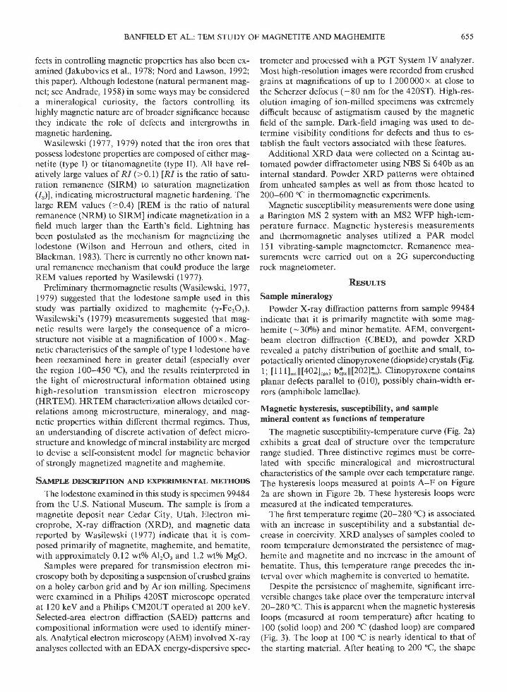
Despite the persistence of maghemite, significant irre-versible changes take place over the temperature interval20-280 "C. This is apparent when the magnetic hysteresisloops (measured at room temperature) after heating to100 (solid loop) and 200'C (dashed loop) are compared(Fig. 3). The loop at 100 "C is nearly identical to that ofthe starting material. After heating to 200 oC, the shape
BANFIELD ET AL.: TEM STUDY OF MAGNETITE AND MAGHEMITE

656
Fig. l. (a) A bright-field transmission electron micrographshowing magnetite (Mt) and maghemite (Mht) that are subdi-vided by numerous planar features. Planar faults [parallel to (020)]are apparent in the included topotactically oriented clinopyrox-ene. These may be chain-width errors (i.e., amphibole). (b) Aselected-area electron diftaction pattern from clinopyroxene [402]and magnetite I I l]. Clinopyroxene b* is parallel to [202]* ofmagnetite. (c) A dark-field image formed using the 202 reflec-tion. Two of the three sets of defects are clearly visible.
BANFIELD ET AL.: TEM STUDY OF MAGNETITE AND MAGHEMITE
of the loop changes dramatically, with the field requiredto close the loop changing from about 0.35 to 0. 15 T.The high coercivity exhibited by the loop is lost by 200"C. These results imply magnetic softening unrelated toany change in the magnetic mineralogy (e.9., the conver-sion of maghemite to hematite).
The second temperature regime (-280-425'C), char-acterized by a precipitous drop in the sample's suscepti-bility and saturation magnetization (about 20-300/o of thevalue of f. is lost), corresponds to the destruction ofmaghemite. XRD analyses showed the replacement ofmaghemite by hematite.
The third temperature regime (from 425 'C to the Curiepoint and then back to room temperature) is character-izedby the typical susceptibility peak for magnetite nearthe Curie point (Hopkinson Peak) and gradual increasesin the susceptibility and coercivity on cooling. The min-erals present in the final sample are magnetite and he-matite. The breadth of peaks from magnetite and he-matite in powder XRD patterns (compared with massivemagnetite) attests to the presence of crystals with sizes inthe submicrometer range in the final assemblage of inter-grown minerals.
The hysteresis loop after cooling from 600'C has adifferent shape compared with that for the unheated sam-ple. The loop for the untreated material (Fig. 2b,loop A)is unusual in that it is of constant width over its entirelength. In comparison, the loop for material cooled fromits Curie point (Fig. 2b, loop F) has its maximum widthnear the origin and tapers to closure at higher fields.
Thermal demagnetization of the naturalremanent magnetization (NRM)
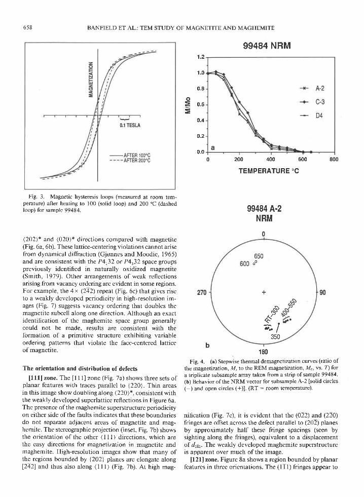
The thermal demagnetization curves for triplicatespecimens are essentially identical (Fig. 4a). About 800/oof the NRM is demagnetized by 300'C, i.e., before theconversion of 7 to a-FerO.. This demagnetization is co-incident with the large increase in Xo (susceptibility) andthe corresponding decrease in coercivity. About l5olo ofthe NRM is demagnetized with the conversion of 7- +a-FerO. between 300 and 400 "C, leaving about 5olo ofthe remanence associated with a-FerO, and FerOo. Theinclination of the NRM direction is essentially constantduring demagnetization to 550 oC. However, in detail,the declinations cluster for demagnetization to 300 "Cand then from 400 to 550 "C.
The points at 600 and 650 "C in the thermal demag-netization curve are essentially antipodal to those oftheFe.Oo (Fig. 4b). These points are associate$ with a-FerO,that was produced by the conversion of ^y- to a-FerO..The reversed NRM of hematite compared with magnetitesuggests chemical remagnetization in the laboratory. Thiseffect was not studied in detail.
Remanence and remanence acquisitionThe remanent magnetization of sample 99484 is suffi-
ciently intense to justify its classification as a lodestone(Wasilewski, 1977). The ratio of saturation remanence to

194"B
285.c
+ H E A T I N G
- $ c 0 0 L t N G
45"F 3m"
E415"
D
0 100 200 300 400 500 600 700
saturation magnetization (RI) is in the range 0. 18-0.26,compared with values of <0.02 for normal massive mag-netite. The REM values (SIRM imparted in a l-T mag-netic field) for seven subsamples range from 0.4 to 0.67.Assessment of all remanent magnetization mechanisms(Nagata, 196l; Stacey and Banerjee, 1974) and compar-ison with more than a thousand determinations for alltypes of natural materials studied at the NASA God-dard laboratory (REM values < 0.08) indicate thatthese REM values are abnormally large for naturallymagnetized materials.
Remanence-acquisition curves for sample 9948a (Fig.5) indicate that magnetic fields in excess of 0.05 T arerequired to produce the REM values measured for thelodestone. The only way to explain thege large REM val-ues is to identify a natural mechanism by which magne-tite is exposed to a large field. The hypothesis advancedby Wilson and Herroun, that the magnetization is due tolightning strikes, has been widely considered (Blackman,1983) and is supported by our data.
The shape of the remanence-acquisition curve (Fig. 5)is nearly identical to that for l-rrm magnetite particles(Thompson, 1986), despite the massive nature of thelodestone samples. Specifically, the field required toachieve one-halfofthe saturation remanence is about 50mT. The results of Thompson (1986) for l-pm magnetitediffer from those for sample 99484 in the shape of thehysteresis loop as saturation is approached (the final l5-200lo of the remanence is acquired slowly in fields in ex-cess of 0. I T). The remanence-acquisition curves before
18000
1 6000
BANFIELD ET AL.: TEM
LODESTONE 99484a
STUDY OF MAGNETITE AND MAGHEMITE 657
MAGNETIC HYSTERESIS LOOPS(Hn=t ITESLA)
heating and after heating to 600 'C are similar, notablybecause of the overwhelming influence of FerOo.
Heating to -285 'C substantially reduces the coercivity(Fig. 2), yet samples cooled from temperatures rn excessof those associated with the maghemite to hematite trans-formation have a high coercivity. Thus, it can be inferredthat the microstructure responsible for the acquisition ofremanence in samples after heating to 600 "C must differfrom that in untreated samples. The final high coercivitymust be associated with the size, shape, and distri-bution of magnetite within the composite of magnetiteand hematite.
The levels of saturation remanence observed in sample99484 require the presence of a microstructure. Withoutsufficient microstructural hardening, massive magnetitecould not be made into a lodestone, even in fields of I T.Consequently, we must turn to the microstructural anal-ysis to understand fully the magnetic characteristics ofthe lodestone.
Microstructural characterization
SAED patterns from extensive areas ofiron oxide oftenshow slight splitting of reflections consistent with thepresence of both magnetite and maghemite. Some areas,such as the one illustrated in Figure l, give rise to weakmaghemite reflections in SAED patterns (e.g., Fie. 6).These regions are common but sporadically developed.
The most frequently observed arrangement of super-structure reflections involves violation of the face-center-ing systematic absences, resulting in doubling along the
> 14000F
fr rzoooFo.u 10000oaA sooo
S 6000
=
TEMPERATURE'C
Fig. 2. (a) Initial magnetic susceptibility-temperature (Xo-T) heating and cooling curves for sample 99484. The letters A-F atthe indicated temperatures correspond to the points at which hysteresis loops shown in b were measured. (b) Magnetic hysteresisIoops labeled A-F correspond to the letters A-F at temperatures indicated on the Xo-Z curves in a. These loops were measured atthe temperature indicated. Loop A is the starting material at room temperature, and F is the room temperature loop for the materialafter the complete thermal cycle (room temperature to 600 "C to room temperature). Hn: ll T.
658 BANFIELD ET AL.: TEM STUDY OF MAGNETITE AND MAGHEMITE
99484 NRM
0.8
o= 0.6=
0.4
o.2
0.0200 400 600
TEMPERATURE'C
99484 A-2NRM
180Fig. 4. (a) Stepwise thermal demagnetization curves (ratio of
the magnetization, M, to the REM magnetization, Mo, vs. T) fora triplicate subsample array taken from a strip of sample 99484.(b) Behavior of the NRM vector for subsample A-2 [solid circles(-) and open circles (+)1. (RT : room temperature).
nification (Fig. 7c), it is evident that the (022) and (220)fringes are offset across the defect parallel to (202) planesby approximately half these fringe spacings (seen bysighting along the fringes), equivalent to a displacementof d2a2. The weakly developed maghemite superstructureis apparent over much of the image.
ll2llzone. Figure 8a shows a region bounded by planarfeatures in three orientations. The (l I l) fringes appear to
1 .2
1.0
Fig. 3. Magnetic hysteresis loops (measured at room tem-perature) after heating to 100 (solid loop) and 200'C (dashedloop) for sample 99484.
(202)* and (020)* directions compared with magnetite(Fig. 6a, 6b). These lattice-centering violations cannot arisefrom dynamical diffraction (Gjonnes and Moodie, 1965)and are consistent with the P4,32 or P4r32 space groupspreviously identified in naturally oxidized magnetite(Smith, 1979). Other arrangements of weak reflectionsarising from vacancy ordering are evident in some regions.For example, the 4 x (242) rcpeat (Fig. 6c) that gives riseto a weakly developed periodicity in high-resolution im-ages (Fig. 7) suggests vacancy ordering that doubles themagnetite subcell along one direction. Although an exactidentification of the maghemite space group generallycould not be made, results are consistent with theformation of a primitive structure exhibiting variableordering patterns that violate the face-centered latticeof magnetite.
The orientation and distribution of defects
[111] zone. The I I l] zone (Fig. 7a) shows three sets ofplanar features with traces parallel to 1220\. Thin areasin this image show doubling along <220)*, consistent withthe weakly developed superlattice reflections in Figure 6a.The presence of the maghemite superstructure periodicityon either side ofthe faults indicates that these boundariesdo not separate adjacent areas of magnetite and mag-hemite. The stereographic projection (inset, Fig. 7b) showsthe orientation of the other ( I I I ) directions, which arethe easy directions for magnetization in magnetite andmaghemite. High-resolution images show that many ofthe regions bounded by {2021 planes are elongate along[242] and thus also along ( I I I ) (Fig. 7b). At high mag-
650oo
+
.^ss#--:- ,-_ l
350

oor REMANEN.EoA:eursrtoN
Fig. 5. Remanence-acquisition (ratio of rnagnetizalion, M,to REM magnetization, Mo, as a function of the applied field inunits ofTesla) curves for 99484. Open circles correspond to theoriginal starting material, and solid circles correspond to thesame sample measured after heating to 650'C.
be offset by approximately Y:[ll] across boundariesmarked P, and P, in Figure 8a. These defects [parallel to(220) and (022)l are marked by wide bands of dark con-trast (-2 nm) because they are inclined to the electronbeam. Offsets of approximately half the (l I l) spacing oc-cur along short sections parallel to (202) (arrows in Fig.8a). The (1Tl) fringes are not offset across the faint planarfeatures parallel to (202) (P, in Fig. 8a).
[101] zone. Images obtained down [101] show inclinedfeatures in two orientations. These features are parallelto the (220) and (022) planes. Figure 9 illustrates thatlattice fringes are offset across these defects.
ll4llzone. Images down [41] show both vertical andinclined planar features (Fig. 10a). At higher magnifica-tions it is apparent that vertical defects are parallel to(202). Defects parallel to (202) are interruptedby zigzagsegments of inclined features (producing striped contrast)parallel to (220) and (022) (Fig. I 0b).
Trace results. Trace results from all the zones reportedabove are consistent with the presence ofdefects parallelto the {202} planes (dodecahedral form). Thus, these de-fects share the known orientation of the domain walls inmagnetite (Stacey and Banerjee, 197 4).
Fault displacement from HRTEM images
High-resolution images from the [111] zone indicatethat the faults are associated with an apparent (projected)displacement equivalent to d2a2. This is approximatelyconsistent with the projected h[Tl] displacement indi-cated by offset of fringes in the [21] zone, and it is inagreement with a [Y+0Yr] translation within the fault plane(Fig. l l). On the other hand, faults showing no offset of(l I l) fringes in the [121] zone apparently do not involvea translation.
659
Fig. 6. Selected-area electron diftaction patterns: (a) the I I l]zone from the area shown in Fig. I illustrating weak I l0 reflec-tions that should be absent in magnetite; (b) the I l0] zone il-lustrating weak 001 and I l0 type reflections that should be ab-sent in diffraction patterns from magnetite; (c) the I I l] zoneshowing superstructure reflections indicating a 4 x multiple of\242) magnetrte.
Displacements estimated from HRTEM images were
tested by comparing the observed with the expected vis-
ibility (Hirsch et al., 1977) using dark-field images formed
with different reflections. Contrast from faults is deter-
mined by the phase change a: 2rg'R across the fault (g
BANFIELD ET AL.: TEM STUDY OF MAGNETITE AND MAGHEMITE

660 BANFIELD ET AL.: TEM STUDY OF MAGNETITE AND MAGHEMITE
Fig. 7 . (a) Transmission electron micrograph of the I I I I ] zone illustrating three sets of planar features with traces parallel to{ I l0}. Areas showing doubling are indicated by arrows. (b) Stereographic projection for the [1 I l] zone. (c) High-resolution imageshowing that (022) and (220) fringes are offset by the defect parallel ro the (202) planes.
: reciprocal lattice vector; R : fault vector). For exam-p l e , w h e n a : 0 , 2 t r ( g . R : 0 + l , + 2 , . . . + n , w h e r e nis an integer), there is no contrast. We evaluated the dis-placement vectors associated with many faults. Examplesfrom two areas are given below.
Displacement vector analysis by dark-field imaging
flllf zone. A dark-field image formed using lhe 202reflection for the area in Figure la is shown in Figure lc.Comparing these images shows that faults in two orien-tations parallel to the (022) and (220) planes are highlyvisible, whereas the faults parallel to the (202) planes areeffectively invisible. These observations can be analyzedusing the visibility criteria noted above; the results areshown in Table l.
ll2ll zone. Dark-field images of an area were formedusing the 404 reflection (Fig. I 2a), the 3 lT reflection (Fig.l2b), and the 628 reflection (Fig. 12c). The bright-field
image obtained with the beam parallel to [121] (Fig. l2d)illustrates inclined defects [parallel tothe (220) and(022)planesl that show fringe offsets and vertical defects par-allel to the (202) planes that show no fringe offset. InFigure I la and I lb, the faults that offset the (l I l) fringesare effectively invisible. In Figure l2a the defects parallelto the (202) planes are somewhat visible, and in Figure1 2b they are nearly invisible. In Figure I 2c the (202) and(022) defects are clearly visible, whereas those parallel to(220) are invisible. Results are analyzed in Table l.
Observations indicate that faults for which a transla-tion was found are in contrast under the conditions ex-pected for a displacement vector with a length of 0.297nm (equal to lhe 220 interplanar spacing) contained with-in the fault plane, and thus they are stacking faults withtranslations of the type |V4th}l. The stacking faults pre-serve the arrangement of O atoms. The boundary struc-ture is illustrated in Figure l3a. Faults that do not offsetthe (1I l) fringes in the [21] zone cannot have a (y4V40)

BANFIELD ET AL.: TEM STUDY OF MAGNETITE AND MAGHEMITE 66r
Fig. 8. (a) Transmission electron micrograph of the [21] zone showing the traces of planar features in three orientations (P',
P,, Pr). The (1T1) fringes are offset by the two sets ofinclined defects (P,, Pr). (b) Stereographic projection for the [121] zone.
displacement and show contrast that is inconsistent witha translational displacement of this type.
Contrast alternation in dark-field images. Figure l4 isa dark-field image (242 reflection) from an area exhibitinga well-developed maghemite superstructure. Two of thethree sets of faults are visible in this image. Effective in-visibility was achieved under dark-field conditions usingthe 440 reflection, suggesting that these boundaries alsoinvolve a[thth}]-type translation. The image shows alter-nation of contrast associated with the fault boundaries. Itis difficult to attribute contrast alternation to differentmagnitudes for the 242 structure factors in alternate
regions (e.g., ifthe faults separate regions ofleft and rightvariants of maghemite), as these differences will be small.Contrast alternation may in part reflect strain associatedwith the defects (G. Nord, 1993 written communication).
Microstructure of the sample heated to 200 "C
The sample heated to 200'C in the susceptibility-tem-perature experiments (Fig. 2a) was characterized by XRDand its microstructure examined by TEM. Most of thefragments composed of maghemite and magnetite ap-peared to be devoid ofstacking faults, although occasion-al dislocations were present. Some small regions exhib-
1t4 0 u4)
0 r l1 r l4l. ul4 r/4 0
vqt

662 BANFIELD ET AL.: TEM STUDY OF MAGNETITE AND MAGHEMITE
TABLE 1. Determination of disolacement vectors for faults basedon visibility criteria for g : 202,404, 31 1, and 628
Visibility
a : 2 r g - R Predicted ObservedFaultp lane g.R
+ T- t
0
2r-2r
0
2r0
(2201(0221(2021
(220)(022l(2o2)
(2201(o22)(2021
(2201(0221(202)
(202)'Iv4u40l(202).[0v4u4](202) [ua0ua](4041 [ue1h0)(404) IOU4v4l(O\ funOua](3't1).lv4u40l(311).[Ouaual(311)-[VeOVa]
(628) w4U4OI(628) IOV+uel(6281 lu40v4l
visiblevisibleinvisible
invisibleinvisibleinvisible
invisibleinvisiblevisible
invisiblevisiblevisible
visiblevisibleinvisible
invisibleinvisiblevisible
invisibleinvisibleinvisible
invisiblevisiblevisible
4r_ e *
_ T
Fig. 9. Image down [01] illustrating that lattice fringes areoffset across an inclined defect [defect parallel to (220)].
ited the characteristic stacking-fault microstructuredescribed in the unheated lodestone. The microstructurepresent within clinopyroxene lamellae was unchanged.
DrscussroNThe very high REM and saturation remanence values,
the susceptibility-temperature behavior, thermal demag-netization results, and remanence-acquisition character-istics all indicate that the distinctive magnetic propertiesof lodestone sample 99484 must be explained by consid-eration of the minerals and their microstructures. Fur-thermore, understanding of the thermal stability of themagnetic properties requires characteization of changesin mineral content and microstructure with temperature.
High-resolution imaging, electron diffraction, traceanalysis, and fault vector analysis have been used to an-alyze the distribution, orientation, and displacement vec-tors of defects in the lodestone sample. The results indi-cate that the sample is subdivided into domains that aretypically only a few tens of nanometers wide by planarfaults, many of which offset the magnetite substructure.Images such as Figure 7c suggest that the fault width issmall (<0.6-nm wide) and that a second phase severalunit cells wide is not developed along these features.
The presence ofa weakly developed superstructure in-dicates that some of the magnetite in the lodestone spec-imen has been oxidized to form maghemite. This reac-tion can be written 3Fe.Oo + 0.750, + 3H+ + 47-FerO,+ Fe3+ + l.5H,O. Wasilewski (1977, 1979) suggestedthat the sample was composed of finely intergrown, al-ternating lamellae of maghemite and magnetite. How-ever, the presence of the maghemite superstructure on
Fig. I 0. (a) A I I 4 I ]-zone image showing contrast associated with inclined defects; (b) a stereographic projection for the I I 4 I ] zone.

BANFIELD ET AL.: TEM STUDY OF MAGNETITE AND MAGHEMITE 663
1/2 d (101 )= 11t4 0 1 t4J
Fig. I l. Diagram illustrating that projected translations areconsistent with a [y40y4] Burgers vector.
either side of boundaries indicates that stacking faultscommonly separate adjacent regions of maghemite andnot magnetite from maghemite.
Maghemite microstructures
Maghemite exhibits superstructure reflections that aregenerally consistent with the enantiomorphic space groupsP4,32 and P4r32 reported for maghemite by Smith (1979).Smith (1979) discussed seven boundaries with (YzVz0)translations that are expected when magnetite convertsto maghemite with these structures. In our samples, pla-nar features showing no offset of the magnetite substruc-ture (Fig. 8a, Pr) might be boundaries between adjacentmaghemite domains.
Microstructures involving the magnetite subcell
Offsets for faults parallel to { 10 I } were determined byHRTEM imaging and dark-field experiments involvingsubcell reflections. Results show that most boundaries inmaghemite and magnetite can be described as stackingfaults with a (thlhj) displacement. Because these bound-aries offset the magnetite substructure, they cannothave formed simply as the result of vacancy creationduring oxidation.
Hornstra (1960) considered defects in spinel from atheoretical perspective and suggested that the most likelyslip plane is {l l l}. However, Lewis (1966) showed ex-perimentally that the principal glide system for nonstoi-chiometric spinels was of the type {l l0}(l l0). Lewis re-
Fig. 12. Dark-field images formed using (a) the 404 reflec-tion, (b) the 3TT reflection, and (c) the 628 reflection. (d) Bright-field [121]-zone image for the area shown in a, b, and c. Thearrows indicate planar defects that do not offset the (l I l) fringes.
664
1/2 d (ioi)
ut tetraneoral
O W ocrahedral
Oxygen
BANFIELD ET AL.: TEM STUDY OF MAGNETITE AND MAGHEMITE
0 6 n m
a)(a)
m m m
l l l
ioounoary
ox ox
Xo* / t \ o *
(b)242
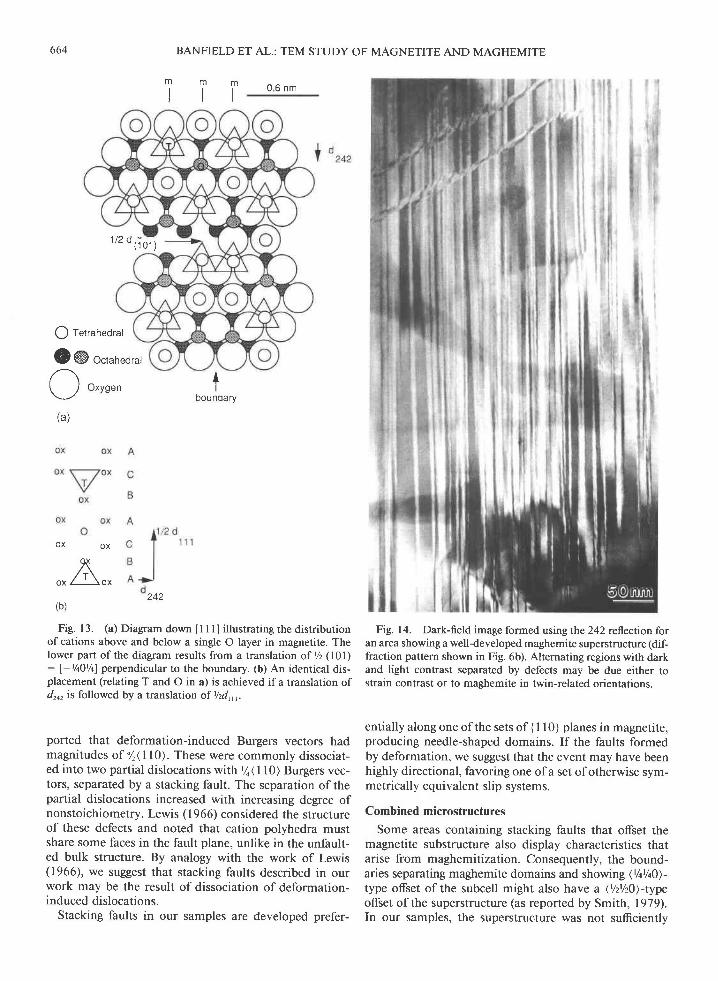
Fig. 13. (a) Diagram down I I l] illustrating the distributionofcations above and below a single O layer in magnetite. Thelower part ofthe diagram results from a translation of Yz (l0l): f-t/eOt/el perpendicular to the boundary. (b) An identical dis-placement (relating T and O in a) is achieved ifa translation ofdro, is followed by a translation of Vzdr,r.
ported that deformation-induced Burgers vectors hadmagnitudes of '/r(ll0). These were commonly dissociat-ed into two partial dislocations with'/o\ I l0) Burgers vec-tors, separated by a stacking fault. The separation ofthepartial dislocations increased with increasing degree ofnonstoichiometry. Lewis (1966) considered the structureof these defects and noted that cation polyhedra mustshare some faces in the fault plane, unlike in the unfault-ed bulk structure. By analogy with the work of Lewis(1966), we suggest that stacking faults described in ourwork may be the result of dissociation of deformation-induced dislocations.
Stacking faults in our samples are developed prefer-
Fig. 14. Dark-field image formed using the 242 reflection foran area showing a well-developed maghemite superstructure (dif-fraction pattern shown in Fig. 6b). Alternating regions with darkand light contrast separated by defects may be due either tostrain contrast or to maghemite in twin-related orientations.
entially along one of the sets of { I l0} planes in magnetite,producing needle-shaped domains. If the faults formedby deformation, we suggest that the event may have beenhighly directional, favoring one of a set of otherwise sym-metrically equivalent slip syslems.
Combined microstructures
Some areas containing stacking faults that offset themagnetite substructure also display characteristics thatarise from maghemitization. Consequently, the bound-aries separating maghemite domains and showing \Vih})-type offset of the subcell might also have a (Vzt/20)-typeoffset of the superstructure (as reported by Smith, 1979).In our samples, the superstructure was not sufficiently

well developed to show this phenomenon clearly. Thepresence of face-sharing tetrahedral and octahedral sitesalong the fault surface might promote nucleation of ad-jacent domains of maghemite with enantiomorphic cat-ion distribution pattems within the undisturbed O frame-work. This vacancy distribution pattern could minimizethe stacking fault energy.
In summary, the distinctive microstructures of theIodestone specimen are apparently the result of bothstructural faulting of magnetite and its oxidation tomaghemite. Stacking faults might have provided nucle-ation sites (and possibly rapid-diffusion pathways) formaghemite growth, or stacking faults might have devel-oped within maghemitized magnetite.
Magnetic properties and their relation tomicrostructure
In combination, the magnetics experiments (Figs. 2-5)and microstructural analysis provided explanations forthe distinctive properties of lodestone sample 99484 and.the changes in these properties with temperature.
Untreated samples. I-odestone carries a sufficiently largenatural remanence to indicate exposure to a magnetizationevent of a magnitude far in excess of that associated withthe Earth's magnetic field. The REM values (0.4-0.67 forseven subsamples) are much larger than those measured formost naturally magnetized materials. We support the viewthat the high REM values imply an NRM that is composedmostly of a lightning-induced remanenc€.
Remanence-acquisition and coercivity data indicate theimportance of microstructure in establishing the magnet-ic properties of the lodestone. We attribute the distinc-tively high coercivity to the presence ofplanar defects inmagnetite and maghemite. The arrangement of stackingfaults ({101} or dodecahedral form) shares the orienta-tions of normal magnetic domain walls in magnetite (Sta-cey and Banerjee, 1974). Most of the high coercivity ofthe sample can almost certainly be associated with thepresence of these faults, which serve as (or pin) magneticdomain boundaries (e.g., rotation of magnetic vectorswould require nucleation of new domain walls or motionofthe faults).
This role of stacking faults in controlling the coercivityis supported by the work ofJakubovics et al. (1978), whoreported that magnetite formed from hematite in theelectron microscope contained faults on { I l0} planes withvectors ofYq( I l0). They used Lorentz microscopy to showthat stacking faults strongly influenced the magnetic do-main structure, and they applied a simplified model toshow that stacking faults will be low-energy sites for mag-netic domain walls. By analogy with their work, most ofthe natural remanence in our samples is probably asso-ciated with these abundant structural defects.
The shape of the hysteresis loop (constant width untilnear saturation) for unheated sample 99484 is distinctivecompared with that of f inely subdivided magnetite(Thompson, 1986). We suggest that the loop shape forlodestone reflects a mixture of very hard (defect regions)
66s
with relatively soft (defect-free) material, causing the loopto be constricted as it approaches the origin.
Small, topotactically oriented diopside crystals are alsocommon in the sample. Their boundaries are parallelto \2021 fault planes in maghemite (Fig. l). Conse-quently, these features subdivide the sample in the sameway as the faults and, thus, also may contribute tomagnetic hardening.
Most of the images indicate that the structural do-mains, and thus possibly the magnetic domains, are nee-dle-shaped, with elongation along one of the I I l]directions. The shape anisotropy parallel to an easydirection for magnetization (Stacey and Banerjee, 1974)may enhance the ability of the crystals to acquire aunidirectional alignment.
Samples heated to -285 "C. Hysteresis loops decreasedin width considerably throughout the 20-285 oC temper-ature range (A-C in Fig. 2b), indicating very substantialmagnetic softening. Between room temperature and 100'C, the increase in susceptibilitv (X.) was essentially re-versible, and the magnetic hysteresis loop data indicatethat little of the hard magnetization (ascribed to stackingfaults) was altered.
Between 100 and 200'C, the coercivity was diminished(see Fig. 2), and magnetic susceptibility increased steeply( 100- I 50 "C). The susceptibility remained essentially un-changed between 150 and 200 "C. No evidence for anyappreciable conversion of 7- to a-FerO3 was detectedafter heating to 200 'C, but the stacking fault densitywas significantly reduced (some apparently unmodifiedareas remained).
Heating from 200 to about 280 "C was accompaniedby a continuous increase in Xo and a decrease in coerciv-ity. These changes are unrelated to the conversion of 7-to a-FerO. (which occurs at higher temperature) and ap-pear to be directly associated with the elimination ofstacking faults. The plateau in the Xo curve (150-200 "C)is interpreted to indicate a thermal range where somestacking fault configurations are stable, possibly indicat-ing a two-stage process for the elimination of these fea-tures (the first between 100 and 150 "C and the secondbetween 200 and 280 "C). Elimination of stacking faultsmay involve recombination of partial dislocations andreorganization of dislocations to grain boundaries.
The susceptibility increase over the interval 20-280"Cis attributed to the increase in size of magnetic phasevolumes (topotactic Fe.Oo-"y-FerO, regions) due to elim-ination of the faults. The coercivities for the starting ma-teial (22-29 mT) were reduced to l5-20 mT after heat-ing to 300'C (measured at room temperature). Measuredat 300'C, the coercivities were 5-6 mT. These coerciv-ities were larger than expected for coarse multidomainmagnetite, even with hematite lamellae introduced bymoderate amounts of normal oxidation (<5 mT). Thus,the FerOo-7-FerO, regions remain magnetically hard inthe absence offaults. The bounding regions (and any re-constructed defect microstructure) are possible sources ofthis hardness.
BANFIELD ET AL.: TEM STUDY OF MAGNETITE AND MAGHEMITE

666
Thermal demagnetization results (Fig. a) reveal thatthe period of greatest loss of natural remanence corre-sponds with the 20-285 "C temperature interval and, thus,with the dramatic decrease in coercivity. This furthersupports the correlations among coercivity, remanence,and stacking faults, as well as the view that pinning ofmagnetic domain walls to stacking faults gives lodestoneits high natural remanence.
300-600 qC. X-ray powder diffraction patterns con-firmed that heating to temperatures between -300 and425 "C results in the conversion of maghemite to hema-tite. The 7- - a-FezO. transformation has a clear mag-netic signature. The susceptibility and saturation mag-netization decrease rapidly and almost all remaining NRM(-20o/o) is lost.
The coercivity of the hematite-bearing samples wasconsiderably larger than that of samples heated to justbelow the maghemite-hematite transformation. The finalcoercivity of the sample cooled from 600 oC was similarto that of the unheated sample. This implies that a sec-ondary microstructure had been created by the growth ofhematite. Furthermore, the remanence-acquisition curvefor the sample after heating to -600 oC was almost iden-tical to that of the unheated sample. The coincidence ofthe initial and final coercivity values is probably fortui-tous in this case and might be attributed to the specificsofthe shape and distribution ofreaction products, as wellas the strong shape anisotropy of the remaining magne-tite. In a different magnetite lodestone (97425 of Wasi-lewski, 1979), about 500/o of the coercivity was recoveredafter the inferred maghemite - hematite converslon.
The apparently small crystal size of both magnetite andhematite in the demagnetized material (as indicated bypeak broadening in XRD traces) may indicate that thefinal microstructure is composed of magnetite and he-matite intergown on a sufficiently fine scale to inducemagnetic hardening. The hysteresis loop for this material(Fig. 2b, curve F) is similar to that of magnetite withoutan admixed, magnetically very hard component (stackingfault regions).
Both the magnetic measurements and the microstruc-ture place constraints on the timing of events producinglodestone. The high REM value requires that structuralfaulting either predated or formed simultaneously withmagnetization. The anisotropic distribution of faults (andthe absence of similar features in magnetite from otherrocks previously examined by the authors) suggests thatthe events occurred simultaneously. Thus, stacking faultsmay be attributable to shock and the NRM to the mag-netic field associated with a lightning discharge.
Conflicting views have been offered as to the extent towhich CRM preserves the NRM (e.9., Marshall and Cox,l97l; Johnson and Merri l l , 1972, 1973; Pr6vot et al.,l98l; Smith and Banerjee, 1986; Raymond and La-Brecque, 1987; Nishitani and Kono, 1989). In our sam-ples, data suggest that destruction of maghemite is ac-companied by migration of the net magnetization vector,implying that the component carried by magnetite is
BANFIELD ET AL.: TEM STUDY OF MAGNETITE AND MAGHEMITE
slightly skewed from that carried by maghemite. The he-matite with reversed magnetization acquired its rema-nence between 300 and 450 "C during the 'y- - a-FerO,conversion in the presence of magnetite. The magneti-zation residing in FerOo is so intense, even at 550'C, thatonly at 600 "C when FerOo is demagnetized completelydo we see the a-FerO, magnetization.
Gnnenx, rMpLrcATroNs AND coNCLUsroNs
The results of this study emphasize that microstruc-tures can greatly influence mineral magnetic properties.The correspondence of stacking fault and magnetic-do-main wall orientations and the elongation of fault-bound-ed regions along the easy direction for magnetization sug-gest that it is the presence of defects (and, we infer,lightning strikes) that make this sample magnetically dis-tinct from normal, multidomain magnetite.
Defects may have been introduced by an as yet un-identified process before magnetization. However, weconsider it likely that structural faulting occurred simul-taneously with the acquisition of the high NRM. We sup-port the view that lightning discharge was responsibleboth for the magnetization and the development of thestacking faults (probably through dislocation dissocia-tion). The timing of maghemite formation is unclear.However, thermal demagnetization data suggest that theNRM carried by the maghemite is skewed relative to thatcarried by magnetite.
The geometric configuration and thermal dependenceof ^y-FerOo were originally proposed to explain the mag-netic behavior of sample 99484 (Wasilewski, 1979). In-terfacial behavior associated with epitactic intergrowthsof magnetite and maghemite was considered responsiblefor the magnetic hardness of the starting material. It washypothesized that the destruction of maghemite in inter-growths of magnetite and maghemite resulted in elongateregions of magnetite separated by hematite, and this wasconsidered the source of magnetic hardness after heattreatment. Microstructural evidence reported aboveidentifies stacking faults as immobile sites for domainwalls and provides a firm basis for the explanation ofthethermomagnetic behavior of the sample composed ofmagnetite and maghemite. At temperatures below themaghemite-hematite transformation the material is mag-netically softened as structural defects are eliminated.However, the magnetic hardness of the sample after finalheat treatment is related to the destruction of maghemite.Results clarify the role of maghemite and indicate thatmost of the significant magnetic behavior, including rem-anence demagnetization, can be related to the tempera-ture response of stacking faults.
Recognition of microstructures (often with a large shapeaspect) capable of pinning magnetic domain walls or re-tarding wall motion (e.g., ultrafine oxidation products,precipitates, and extended defects) and characterizationof mineralogic and microstructural changes with heatingallow us to refine our interpretations of magnetic data.The structure of the X'-f curve and associated magnetic
hysteresis and thermal demagnetization records are ex-plained by TEM and XRD data on the size and shape ofmagnetic phases and the thermal regimes where stackingfaults and maghemite are stable. Results suggest that thefine structure of the Xo-T curve can be used to localizethermal regimes in which defect activation and phasetransformation (e.9., T - - a-FerOr) are important, pro-viding insights into the thermal stability of features shownto preserve remanence. This might be important for theinterpretation of paleomagnetic records, illustrating, forexample, how magnetic records could be modified duringlow-grade thermal metamorphism.
The rock magnetism literature contains numerous ex-amples of anomalous susceptibility-temperature curvesand studies that contrast thermal and alternating-field de-magnetization results from the same samples. The de-tailed explanation for some of these results might involvemicrostructures and metastable phases that could becharacterized by electron microscopy. For example, Nordand Lawson (1992) presented evidence that composition-ally distinct twin-domain boundaries arising from the or-der-disorder transition in certain ilmenite-hematite seriesphases have a dramatic effect on magnetic properties. Ourdata further demonstrate the importance of microstruc-tures, in this case stacking faults, in magnetic hardeningand in pinning remanent magnetization. Only through anunderstanding of its microstructures can we explain howa piece of magnetite the size of a book can exhibit thecharacteristics of a pseudosingle domain.
Acxxowr,nocMENTS
Special thanks are expressed to Charles Schlinger,6zden 6zdemir, PaulKelso, and David Dunlop for useful suggestions and very helpful discus-sions of the observations reported here. Gordon Nord provided an ex-ceptionally astute review ofthis manuscript. An anonymous reviewer isalso thanked for constructive suggestions. Robert Fudali ofthe U.S. Na-tional Museum provided the lodestone samples. Electron microscopy re-search was supported by a Mineralogical Society of America $ant andNSFgrant EAR-9207041 to J.F.B. and NSFgrant EAR-8903630 to D.R.Y.Magnetics research was supported by the NASA Geology Progam.
Rrrnnnxcns cruEDAndrade, E.N. (1958) The early history ofthe permanent magnet. En-
deavor. 17. 22-30.Blackman, M. (1983) The lodestone: A survey ofthe history and physics.
Contemporary Physics, 24, 3 19-331.Davis, P.M., and Evans, M.E. (1976) Interacting single-domain properties
ofmagnetite intergrowths. Journal ofGeophysical Research, 81, 989-994.
Gjonnes, J., and Moodie, A.F. (1965) Extinction conditions in the dy-namic theory of electron diffraction. Acta Crystallo$aphica, 19, 65-67
Graham, J.W. (1953) Changes of ferromagnetic minerals and their bearing
667
on ferromagnetic properties of rocks. Joumal of Geophysical Research,58,243-260.
Hirsch, P., Howie, A., Nicholson, R.B., Pashley, D.W., and Whelan, M.J.(1977) Electron microscopy ofthin crystals (2nd edition), 563 p. Krie-ger, Malabar, Florida.
Hornstra, J (1960) Dislocations, stacking faults, and twins in the spinelstructure. Physics and Chemistry ofSolids, 15,3ll-323.
Jakubovics, J.P., Iapworth, A.J., and Jolly, T.W. (1978) Electron micro-scope studies of ferromagnetic ordered structures. Journal of AppliedPhysics, 49, 2002-2006.
Johnson, H.P., and Merrill, R.T. (1972) Magnetic and mineralogicalchanges associated with low-temperature oxidation of magnetite. Jour-nal of Geophysical Research, 77 , 334-341.
-(1973) Iow-temperature oxidation of titanomagnetite and the im-plications for paleomagnetism. Journal of Geophysical Research, 78,4938-4949
kwis, M.H. (1966) Defects in spinel grown by the Verneuil process.
Philosophical Magazine, 14, 1003- l0l 8.Marshall, M., and Cox, A. (1971) Effect of oxidation on the natural rem-
anent magnetization of titanomagnetites in suboceanic basalts. Nature,230,28-31
Nagata, T. (1961) Rock magnetism (revised edition), 350 p. Maruzen,Tokyo.
Nishitani, T., and Kono, M (1989) Effect of low-temperature oxidationon the remanence properties oftitanomagnetites. Journal ofGeomag-netism and Geoelectricity, 41, l9-38.
Nord, G.L., Jr., and Lawson, C.A. (1992) Magnetic properties of ilmentitero-hematite,n: Effect of transformation induced twin boundaries. Joumalof Geophysical Research, 97B, 10897-10910.
Pr6vot, M., lrcaille, A., and Mankinen, E.A. (1981) Magnetic effects ofmaghemitization of oceanic crust. Joumal of Geophysical Research,86,4009-4020.
Price, G.D (1980) Exsolution microstructures and their magnetic signif-icance. Physics ofthe Earth and Planetary Interiors, 23,2-12.
Raymond, C.A., and laBrecque, J.L. (1987) Magnetization of the oceaniccrust: Thermoremanent magnetization or chemical remanent magnet-ization? Journal ofGeophysical Research, 92, 8007-8088.
Schlinger, C.M., and Veblen, D.R (1989) Magnetism and transmissionelectron microscopy of Fe-Ti oxides and pyroxenes in a granulite fromI-ofoten, Norway. Journal of Geophysical Research, 9 4, 1 4009 - 1 4026.
Smith, G.M., and Banerjee, S K (1986) Magnetic structure of the upperkilometer of the marine crust at Deep Sea Drilling Project Hole 5048,Eastern Pacific Ocean. Journal ofGeophysical Research, 89l, 10337-10354.
Smith, P.P.K. (1979) The observation of enantiomorphous domains innatural maghemite Contributions to Mineralogy and Petrology, 69,249-254.
Stacey, F.D., and Banerjee, S.K. (1974) The principles of rock magnetism:Developments in solid earth geophysics, vol. 5, 195 p. Elsevier Scien-tific, New York.
Thompson, R. (1986) Modelling magnetization data using SIMPLEXPhysics ofthe Earth and Planetary Interiors, 42, ll3-127.
Uyeda, N. (1958) Thermoremanent magnetization as a medium of paleo-magnetism with special reference to reverse thermoremanent magnet-ization. Japanese Journal ofGeophysics, 2, l-23.
Wasilewski, P.J. (1977) Magnetic and microstructural properties of somelodestones. Physics ofthe Earth and Planetary Interiors, 15,349-362.
-(1979) I-odestone: Explanation for magnetic properties and char-acterization of the source of magnetic hardening. Joumal of AppliedPhysics, 50, 2428-2430
MeNuscnrrr REcETvED Ssmaunen 4, 1992Mnxuscnrgr AccErrED Mnncs 4, 1994
BANFIELD ET AL.: TEM STUDY OF MAGNETITE AND MAGHEMITE