Embed Size (px)
Citation preview

Ultramicroscopy 30 (1989) 217-232 217 North-Holland, Amsterdam
T E M S T U D I E S O F T R A N S F O R M A T I O N I N T E R F A C E S A N D S U B S T R U C T U R E S
IN S O M E C O P P E R - B A S E D S H A P E - M E M O R Y A L L O Y S
Jeff P E R K I N S
Materials Science Group, Naval Postgraduate School, Code 69Ps, Monterey, California 93943, USA
Kenj i A D A C H I
Sumitomo Metal Mining Company, Central Research Laboratory, Ichikawo, Chiba 272, Japan
Ming-Hs iung W U
Memory Metals, Inc., Stamford, Connecticut 06901, USA
and
Tadayashi Y A M A S H I T A
Materials Science Group, Naval Postgraduate School, Code 69Ps, Monterey, California 93943, USA
Received at Editorial Office 6 December 1988; presented at Symposia August 1988
The characterization of interfaces and substructures resulting from solid-to-solid phase transformations is reviewed in the context of three examples in copper-based shape-memory alloys. The first of these concerns the interracial structure of martensite intervariant plate boundaries in a Cu-14.6Zn-16.1A1 (ate) alloy. The atomistic structure of such interfaces, which is important to their mobility and to shape memory behavior, is deduced from the examination of one-dimensional lattice images together with selected-area diffraction data. The second example considers the mechanism of bainitic transformation in a Cu-25.1Zn-9A1 (at%) alloy. In this case, the relative degree of inheritance of parent phase order by the hainite transformation product, which is relevant to the distinction between displacive and reconstructive mechanisms of formation of the bainite, is revealed by the use of dark field imaging techniques using two different types of superlattice reflections. The third case discusses dynamic strain contrast effects and in-situ cooling effects observed in "tweed" microstructures in an aged Cu-47.7Mn-3.5A1 (at%) high damping alloy. The tweed contrast consists of irregular lines of strain contrast lying approximately parallel to traces of {110} planes of the parent FCC phase, and arises in this case due to a tetragonal distortion which occurs, upon cooling, in a dispersion of Mn-enriched regions which have formed upon aging. In addition, a unique "flickering" contrast effect is observed within the tweed contrast. This consists of repetitive movements of short (about 10 rim) lines of contrast; and apparently corresponds to changes in the orientation of the FCC-to-FCT distortion due to the excitation of the incident electron beam. Individual sites of this activity, which are believed to be associated with the mechanism of high damping in these aged alloys, are isolated in weak-beam images. In-situ cooling and video-taping experiments are also described.
1. Introduction
The purpose o f this paper is to review several
specific examples of the appl ica t ion of conven-
t ional t ransmission electron mic roscopy to the
s tudy of interfaces and substructures resulting. f rom sol id- to-sol id phase t ransformat ions . The
three examples which have been selected for dis-
cussion are all based on studies o f t r ans fo rmat ion
mechan i sms in copper -based shape -memory al-
0304-3991 /89 /$03 .50 © Elsevier Science Publishers B.V.
(Nor th -Ho l l and Physics Publ ishing Divis ion)

218 J. Perkins et al. / TEM studies of transformation interfaces and substructures in Cu-based alloys
loys. Each of these cases has interest both from the standpoint of improving our understanding of the metal physics of the relevant transformations and from the standpoint of engineering applica- tion of the unique properties of the alloys.
For example, the first case to be described concerns the characterization of the atomistic structure of the boundaries between martensite plate variants in a Cu-Zn-AI alloy. This is a well-known shape-memory alloy, and the mobility of such boundaries is crucial to the reversal of stress-induced phase transformation upon heating or unstressing, that is, to demonstration of shape- memory behavior [1]. Detailed crystallographic analyses of the martensitic microstructure [2-4], carried out with the assistance of selected-area diffraction data, indicate that there are a variety of different types of intervariant boundary struc- ture, some of which are expected to be more mobile than others. One-dimensional lattice imag- ing also reveals the presence of structural faults within the individual variants; these alter the structure and mobility of the interfaces.
The second example to be considered involves the delineation of the mechanism of bainitic trans- formation in a similar Cu-Zn-A1 shape-memory alloy. There has been a long-running debate in the field of phase transformations over the relative role of displacive (i.e. martensite-like) character as contrasted to reconstructive (i.e. diffusional) char- acter for various bainitic transformations [5]. In the case which will be described here, an unam- biguous determination of the character of the transformation can be made by applying relatively standard techniques of dark field imaging [6]. The associated analysis is based on the fact that the atomic arrangement of the parent phase crystal structure includes two types of order, referred to here as nearest-neighbor (NN) order and next- nearest-neighbor (NNN) order. Therefore, the ap- plication of dark field imaging techniques to par- tially transformed microstructures, using the re- spective superlattice relections, reveals the extent and manner of inheritance of the parent structure by the product bainite, that is, delineates the transformation mechanism.
The third example to be discussed involves the analysis of unique patterns of strain-induced am-
plitude contrast in TEM images of an aged Cu-Mn-al alloy. These results have relevance both to the mechanism by which high damping proper- ties are produced in this alloy, a matter of great engineering interest, and to the manner in which the parent lattice transforms, a subject which is currently of great interest to metal physicists [7]. This particular work has provided some unique results, both from the standpoint of image char- acteristics, in that we sometimes observe certain details of the TEM image contrast to actually move, and from the standpoint of basic principles of lattice stability and diffusionless phase trans- formations that are reflected by these movements [81.
2. Experiment
The alloys examined had the following analyzed compositions: for the intervariant boundary study, Cu-14.6Zn-16.1A1 (at%); for the bainite study, Cu-25.1Zn-9A1 (at%); for the tweed contrast study, Cu-47.7Mn-3.5A1 (at%). In all cases the samples were encapsulated in evacuated quartz tubes for heat treatment. In the intervariant boundary study, the heat treatment consisted sim- ply of solution treatment in the single-phase beta (BCC) range (1123 K for 20 rain) followed by a quench into iced brine (the martensite start tem- perature for this alloy is about 340 K). For the bainite study, the samples were solution-treated at 1173 K for 3 rain and quenched into iced brine (the Ms temperature for this alloy is about 263 K); they were subsequently aged isothermally in salt baths at temperatures between 423 and 623 K. For the tweed study, the Cu-Mn-A1 alloy sam- ples were first solution-treated in the single-phase FCC range (1073 K for 2 h), quenched in water, then aged at 673 K for various lengths of time. Specimen preparation for transmission electron microscopy was in all cases by conventional elec- tropolishing methods, the details of which have been described previously [2,6,8]. The thin foils were examined with either a double-tilt or ro- tation-tilt holder in a JEOL 100CX TEM operat- ing at 120 kV. In-situ cooling and heating experi- ments over a range from 360 to 105 K were

J. Perkins et al. / TEM studies of transformation interfaces and substructures in Cu.based alloys 219
conducted with a Gatan Model 636 double-tilt cooling holder.
3. Results and discussion
3.1. lntervariant boundary structures in C u - Z n - A I
martensite
The characteristic behavior of shape-memory alloys is based on their ability to deform by means of the glissile movement of various interfaces. When considering the deformation of fully martensitic alloys, these interfaces are largely the intervariant boundaries, that is, the boundaries between the various martensite plate variants. Each parent phase crystal (grain) transforms to six plate groups, each consisting of four differently oriented plate variants, conventionally designated A, B, C and D [9]. The six plate groups correspond to the six variants of the {ll0}-type plane in the cubic parent phase, with the habit planes of the four
variants in a given plate group closely clustered around that particular {110}. Therefore, there are actually 24 different orientation variants of martensite derived from each parent phase crystal.
In the C u - Z n - A I alloy examined here, the structure of the martensite is designated 18R, cor- responding to an 18-plane repeat distance for close packed planes (when atomic ordering within the planes is considered), with a stacking sequence (using plane registry positions 1, 2 and 3) that can be designated as 12'32'31'31'21'23'23'13'12', where the primes indicate different ordered arrangements in the planes, i.e. the stacking would be 123231312 and the structure 9R if ordering were ignored. However, one-dimensional lattice imaging of the martensite reveals the presence of fine substructural faults in the 18R martensite which have a 2H structure, as seen in fig. 1. This lattice image was obtained using the (208), (2,0,14), (2,0,20) and (2,0,26) spots in the selected-area diffraction pattern (SADP), which has a [010118R zone axis. The stacking sequence of close-packed
Fig. 1. One-dimensional lattice image showing the fine structure of an 18R martensite plate in Cu-14.6Zn-16.1A1 (at%), obtained by using the (208, (2,0,14), (2,0,20) and (2,0,26) reflections, as indicated in the SADP. The lattice fringe spacing in the 18R matrix is 0.65
nm, while that in the thin fault regions is 0.43 nm, indicating that their structure is 2H.

220 J. Perkins et al. / TEM studies of transformation interfaces and substructures in Cu-based alloys
planes is revealed, and it is clear that whereas lattice fringes of 0.65 nm spacing are seen in the 18R matrix, fringes of only 0.43 nm are observed in the faulted regions. Comparing these fringe spacings with the calculated interplanar spacing of 0.2163 nm, it appears that the distance between two successive black fringes in the matrix involves three atomic layers of (0,0,18) planes, while in the structural faults it represents only two close-packed planes. Therefore, we conclude that these are not simply random stacking faults or slip traces in the 18R structure, but thin slices of a distinctly differ- ent crystal structure, most likely 2H [2]. It should be noted that this inference is only possible through the use of the direct image of the micro- structure, since there is insufficient volume of the fault structure to produce reflections in the SADP.
Within any given plate group of four variants, there are only three types of unique interface, namely the A/B, A / C and A / D types [10]. Two of these, the A /B and A / C types, are founo ~o be highly self-accommodating and are the most corn-
monly found, apparently because they are very effective in accomplishing self-accommodation of transformation strains and due to their greater mobility. Lattice imaging techniques also provide considerable insight into the structure of the vari- ous types of boundaries. For example, an A / C / A variant configuration is shown in fig. 2, and a A / D / A combination in fig. 3. In these relatively low-magnification one-dimensional lattice images, it is immediately evident that the A/C-type inter- variant boundaries are characteristically very straight, whereas the A/D-type boundaries are characteristically very straight, whereas the A/D- type boundaries are quite wavy. For the A / C boundary of fig__2, the trace of the boundary can be indexed as (128)18R referred to the A plate. The SADP shows that the (128)18R planes of the A and C variants are exactly in conjunction with one another, that is, a plane stacking sequence 12'3 etc. in the A variant makes a plane-by-plane match with a stacking sequence 12'3 etc. in the C variant. In the image of fig. 2 , both sets of close-packed
Fig. 2. One-dimensional lattice image of a region containing a thin plate of martensite variant C sandwiched between variants A, taken under the same diffraction conditions as fig. 4. Notice the very straight A / C intervariant boundaries, and the slight taper of the
C variant crystal.

J. Perkins et aL / TEM studies of transformation interfaces and substructures in Cu-based alloys 221
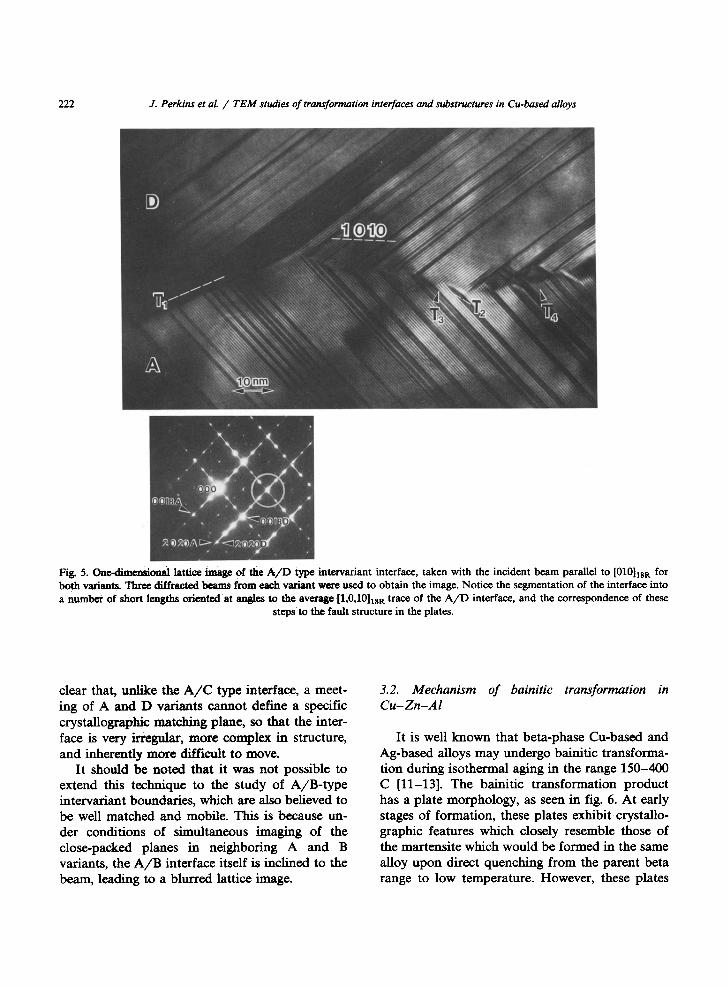
In the case of the A / D type interface, noted earlier to be much more irregular than the A / C type, it is obvious in fig. 3 that microscopic seg- ments of the interface are misaligned with respect to the average trace, which is analyzed to be close to (1,0,10)lSR. In the higher magnification image of this type of interface shown in fig. 5, we see this more clearly, and notice that the interface is also wandering as it passes through the thin foil. It is
Fig. 3. Dark-fidd imaging of a region containing an A/D/A variant combination. The viewing direction is along [010]18R for both variants. Notice the wavy nature of the A/D inter-
variant boundaries.
planes are perpendicular to the plane of the image, and obviously at an angle to one another.
When this type of interface is observed at higher magnification, as in fig. 4, the junction between the A and C variants is observed to be quite smooth, but with slight steps at places where the 2H structural faults meet the interface. F r o m this it is concluded that the manner in which the variant crystals taper to a point is microscopically accomplished through segments of (128) interfaces stepped at structural fault regions [2]. We can also speculate on the mobility of this type of interface f rom the information in the lattice image. We notice, for example, that the matching between the 12'3 etc. stacks of planes in the two variants is generally disturbed in regions where the 2H structural faults meet the interface. Close inspect- ion of fig. 4a shows a matchup of black-to-black and white-to-white fringes between points 1 and 2, but a reversal between 3 and 4 due to the intro- duction of a 2H structural fault between 2 and 3. I t has been verified that this change in contrast is not due to changes in imaging conditions f rom place to place. The implication of this is that the extent of atomic matching at the boundary is diminished by the structural faults, so that the mobility would be expected to be somewhat less.
Fig. 4. One-dimensional lattice image of the A/C type inter- variant interface, taken with the incident beam parallel to [21011sR. Three diffracted beams contribute to the formation of the lattice fringe image in each martensite variant, as indicated in the SADP. The trace of the A/C boundary is (128)1SR referred to the A variant. Notice the small steps in the interface, and the change from white-to-white to white-to-black
correspondence of fringes across the boundary.
222 J. Perkins et al. / TEM studies of transformation interfaces and substructures in Cu-based alloys
Fig. 5. One-dimensional lattice image of the A / D type intcrvariant interface, taken with the incident beam parallel to [010]1st t for both variants. Thr~ diffrac.t~ beams from each variant weze used to obtain the image. Notice the segmentation of the interface into a number of short lengths oriented at angles to the avorag¢ [1,0,10]18R trace of the A / D interface, and the correspondence of these
steps to the fault structure in the plates.
clear that, unlike the A / C type interface, a meet- ing of A and D variants cannot define a specific crystallographic matching plane, so that the inter- face is very irregular, more complex in structure, and inherently more difficult to move.
It should be noted that it was not possible to extend this technique to the study of A/B-type intervariant boundaries, which are also believed to be well matched and mobile. This is because un- der conditions of simultaneous imaging of the close-packed planes in neighboring A and B variants, the A /B interface itself is inclined to the beam, leading to a blurred lattice image.
3.2. Mechanism of bainitic transformation in Cu-Zn-AI
It is well known that beta-phase Cu-based and Ag-based alloys may undergo balnitic transforma- tion during isothermal aging in the range 150-400 C [11-13]. The bainitic transformation product has a plate morphology, as seen in fig. 6. At early stages of formation, these plates exhibit crystallo- graphic features which closely resemble those of the martensite which would be formed in the same alloy upon direct quenching from the parent beta range to low temperature. However, these plates

J. Perkins et al. / TEM studies of transformation interfaces and substructures in Cu-based alloys 223
Fig. 6. (a) Bright field image of a Cu-25.1Zn-9A1 (at%) alloy partially transformed, after holding 48 h at 423 K, from the/~3 matrix phase to plates of the a 1 phase (bainite); (b) superimposed images of the NN APDBs from the f13 matrix and the a 1 plates, obtained
using the ~'2 ~3 and 228 a 1 reflections, respectively; the accompanying SADPs indicate the diffraction conditions involved.
have also undergone a compositional adjustment, therefore defining them as bainite plates, the product of a bainitic reaction. This apparently dual nature (martensitic and diffusional) has led to considerable controversy as to whether the shear aspect or the diffusional aspect controls the trans- formation [51.
In the present case, the parent phase to the bainite is atomically ordered, and in fact there are two types of order present. Above about 800 K, this phase possesses an A2 structure, that is, dis- ordered BCC, designated as t h e / ] phase, which goes through two ordering transitions upon cool- ing. The first of these is a nearest-neighbor (NN) ordering reaction which results in a B2, CsC1,
superlattice, designated as/]2- Further cooling in- duces next-nearest-neighbor (NNN) ordering and the resulting structure has been suggested as the DO3, Fe3A1, superlattice, designated as the 131 phase. However, closer examination has shown that the N N N ordered structure in the present off-stoichiometric alloy actually creates the closely related L21, Cu2MnA1, superlattice, designated as the/]3 phase [6]. The B2 and L21 ordering temper- atures are about 800 and 550 K, respectively [6].
This parent phase ordering turns out to be fortuitous in terms of allowing delineation of the formation mechanism of the bainite plates. The development of both types of order lead to an array of anti-phase domains (APDs), and the

224 J. Perkins et al. / T E M studies of transformation interfaces and substructures in Cu-based alloys
Fig. 7. (1) Bright fidd images and (2), (3) dark field images showing NN APDBs (2) and NNN APDBs (3) in the/83 matrix and a 1 plates after holding at 423 K for times of 96, 240 and 720 h. The NN APDB images were obtained with 222 f13 and 228 a 1 reflections and then superimposed. The NNN APDB images were obtained simultaneously for both phases using 111 f13 and 111 a 1 reflections,
which nearly overlap in ro:iprocal space.

J. Perkins et al. / TEM studies of transformation interfaces and substructures in Cu-based alloys 225
Fig. 8. (1) Bright field images and (2), (3) dark field images showing N N APDBs (2) and N N N APDBs (3) in the r3 matrix and a 1 plates after holding at 473 for 3, 8 and 24 h. The imaging scheme was the same as used in fig. 7. A [12019 R zone pattern is shown in
(c3) to demonstrate the absence of N N N ordering in the a 1 plates after 24 h at 473 K.

226 J. Perkins et al. / TEM studies of transformation interfaces and substructures in Cu-based alloys
boundaries between these donlain.q (APDBs) may be imaged in dark field by using the appropriate superlattice reflections in the SADPs. At tempera- tures below the fl2-to-fl3 ordering temperature, both NN and NNN, and the associated APDBs, are inherited by and preserved in the product bainite, as can be seen in Figure 6. The matching and continuity of of the NNN APDBs between the f13 matrix and the bainite plates in fig. 6b suggests that the essential process of formation of the plates has been a shear mechanism. During subsequent plate thickening, that is, if held longer at the transformation temperature, NNN order is lost, but NN order and the associated APDB structure are perfectly preserved, leading to com- posite bainite plates consisting of an 18R central layer and 9R outer layers, as seen in_fi.i.i.i.~s. 7 and 8. In all these images, the 228 a 1 and 222 f13 reflec- tions in the SADPs were used to image the NN APDBs; a slight tilt is required between these two conditions in order to achieve strongly diffracting conditions for the respective reflections, so that the dark field images for the bainite and the matrix were obtained independently and then su- perimposed in printing. In order to image the NNN APDBs, the 111 et a and 111 f13 reflections were used. Since these two reflections essentially overlap in reciprocal space, it is possible to simul- taneously image the NNN APDBs of both phases. Using this imaging technique, it has been possible to establish that the bainite plate thickness corre- sponding to the 18R-to-9R transition decreases with increasing transformation temperature.
On the basis of these observations, it is con- cluded that the formation and early growth pro- cess of bainite in this alloy involves a shear (martensitic) mechanism, so that both NN and NNN order and the associated APDBs are in- herited. Subsequent plate thickening appears to be controlled by long-range diffusion where effective atomic jumps are confined to the NNN sublattice, since NN order and APDBs are still preserved [6]. Therefore, it is likely that a good deal of the long-running controversy over the mechanism of bainitic transformation has been due to dif- ferences in the temperature and time scales of observation, since the controlling mechanism (shear or diffusion) changes with both of these
variables. Therefore, it is probable that among the transformation products which have been histori- cally identified as balnite, some have formed un- der conditions of control by the shear mechanism aspect, some under control of long-range diffu- sion, and some in a mixed manner. This makes much of the historical argument largely moot, since the mechanism is not always one way or the other. The present work provides an unambiguous delineation of conditions under which the mecha- nism is wholly shear-controlled, that is, where a product identifiable as bainite initiates with a shear-controlled mechanism, with diffusion con- trol taking over only at later stages of growth.
3.3. Tweed microstructures in an aged C u - M n - A I alloy
Manganese-rich Cu-Mn solid solutions are well known to undergo a diffusionless lattice transfor- marion FCC-to-FCT [14]. Upon cooling, the FCC structure initially experiences an antiferromag- netic ordering transition [15]. This initiates a grad- ual tetragonal distortion [16] which eventually car- des the structure into a twinned FCT microstruc- ture [17,18] which may be regarded as quasi- martensitic. It is also well known that a miscibihty gap exists in the Cu-Mn phase diagram [19,20], and that FCC solid solution alloys aged within this field decompose into lVl.n-rich and Mn-poor regions [21]; the following discussion concerns observations on such aged alloys.
For an aging temperature of 673 K, an alloy Cu-47.7Mn-3.5A1 (at%) displays a "mottled" contrast for aging times less than 4 h, as seen in fig. 9a, but develops a "tweed" contrast micro- structure for aging times of 4 h or more, as seen in fig. 9b. The term "tweed" has become a generic term for a particular sort of diffraction contrast in TEM images. This typically consists of irregular lines of contrast lying approximately parallel to traces of {110} of a cubic parent phase, forming a sort of cross-hatched pattern. There are two basic requirements for the appearance of tweed con- trast: (i) a source of finely distributed centers of asymmetric strain, and (ii) an elastically aniso- tropic matrix phase. There are a variety of alloys in which tweed contrast is observed, and these

J. Perkins et al. / TEM studies of transformation interfaces and substructures in Cu-based alloys 227
Fig. 9. Variation in image contrast in Cu-47.7Mn-3.5AI (at%) after various aging times at 673 K. (a) After 2 h at 673 K, the FCC shows "mottled" contrast; this is a bright field image obtained with a near-two-beam conditions with the beam direction near (110) and g = 113; a sharply focused slip trace is included for reference. (b) After 10 h at 673 K, well-clef'reed tweed contrast is seen; bright field image with beam direction near (110) and strongly operating g = 002; a sharply focused FCC {111} annealing twin boundary is
included for reference.
may differ in the nature of the first of these requirements, which may be G-P zones [22], fine precipitates [23], ordered domains [24], or simply domains in which there is an incipient lattice transition which distorts the matrix [25]. In the present case, the source of asymmetric straining points is believed to be the distortion of the incipi- ent FCC-to-FCT lattice transition occurring within a dispersion of Mn-enriched regions (MERs) which have formed during aging [8].
The sharpness of a tweed microstructure, that is to say, the degree of alignment and contrast, is therefore dependent on the distribution, the na- ture and the magnitude of the strain centers, as well as the degree of anisotropy of the matrix phase. If any of these factors is deficient, the typical cross-hatched {110} trace contrast will not be observed; in these "weakly tweedy" cases the image will simply present a "mot t led" contrast, as seen in fig. 9a. On the other hand, as the effective- ness of the dispersion increases, in this case such as by further aging (to increase the size and Mn enrichment of the MERs), or by cooling (to in- crease the tetragonality within the MERs), the tweed contrast is observed to increase.
Single surface trace analysis of the tweed con- trast in a large number of specimens indicates that the two sets of contrast striations in the images axe always parallel to traces of {110} planes of the parent FCC phase, as shown in fig. 10. I t is found that the lines of contrast obey extinction rules which are consistent with their being due to (110) shear distortions of {110} planes, in accordance with the definitive analysis by Robertson and Wayman [26]. For example, in fig. 11, we see that a given set of the striations becomes invisible if the operating g-vector is perpendicular to the trace direction. Also, the observed spacing of the stria- tions is a sensitive function of the foil orientation; very slight tilting, while maintaining the same operating reflection in a two-beam condition, can significantly change the apparent spacing of the striations. The observed spacing is also a function of the degree of deviation f rom the Bragg condi- tion, as observation of the tweed near a bend contour reveals, and of the effective extinction distance. Bright field, dark field and weak-beam images f rom the same area may be compared in fig. 12. The weak-beam image was obtained with the fairly standard g / 3 g method, whereby a near-

228 J. Perkins et aL / TEM studies of transformation interfaces and substructures in Cu-based alloys
I
!~i4!i!iii! ¸ ~iiii~iii~
Fig. 10. Trace analysis of the tweed striations finds them to be parallel to {110} traces of the FCC parent phase. This bright field image is taken from a sample aged 8 h at 673 K, with a foil normal orientation near [001] and the g-vector 020 operat- ing strongly in a two-beam diffraction condition. The two major alignment directions obvious in the tweed contrast fall
along traces of (220) and (220) planes.
two-beam condition is set up with a third-order reflection by placing the bright Kikuchi line just outside that reflection, but actually making the image with the first-order reflection, which is weak in that condition.
In the course of examination of the tweed microstructure in this alloy over a range of aging conditions, a unique and remarkable observation was made, one which has not previously been reported in connection with any other tweedy microstructure. I t was noticed that certain tiny areas within the tweed contrast were not com-
pletely static. Rather, as" the tweed was continu- ously observed on the viewing screen of the TEM at sufficient magnification (say 40,000 x or so), an array of specific locations were observed to "flicker", i.e., to fluctuate in terms of the local details of the contrast. This effect consists of spatially consistent and repetitive contrast varia- tions, that is, only certain points flicker, and the contrast variation is always very much the same in nature (although the frequency is not constant). The regions which flicker are on the scale of the tweed spacing, around 10 nm or so. After ex- tended and close observation, it is obvious that the contrast variations are not of an " o n - o f f ' nature, but rather in the form of short sideways movements or rotations of lines of contrast. As there are a great many of these regions active on the viewing screen at any one time, it is not straightforward to make a complete quantitative characterization of the activity. It also presents certain problems in photographic recording by the usual timed exposure methods, but videotape re- cordings have been made and may be subjected to quantitative image analysis. To date, the most successful method for isolating the sites and the character of the contrast shifts has been the use of weak-beam dark field imaging techniques, as ex- emplified by fig. 13, where a very specific geomet- ric form can be seen, which includes a distinct V-shaped feature.
It is believed that the flickering contrast is due to the transition of quite small sections of FCT crystal, probably less than 10 nm in size, switching f rom one orientation to another. This would be consistent with the MERs (formed on aging) hav- ing entered a pre-transformation range wherein the lattice begins to mimic the incipient FCC-to- FCT lattice transformation, but is able to easily switch the tetragonal orientation because of the very low degree of tetragonality. The only previ- ous report we have been able to find of a dynamic TEM image contrast effect similar to the present observation was in connection with the apparent creation and annihilation of omega domains in a T i - M o alloy [27]. A highly enlarged view of one of these flickering regions is shown in the dark field image of fig. 14, which apparently is a "dy- namic" molt6 pat tern produced between over-

J. Perkins et al. / T E M studies of transformation interfaces and substructures in Cu-based alloys 229
Fig. 11. Extinction of one of the traces of the tweed is obtained when the operating g-vector is perpendicular to the trace direction. Here we see in (a) and (b) that the (220) traces are invisible with g = 111 and g = 220, indicating that the strain displacement vector for this part of the tweed contrast is d(~0) ffi [110]. On the other hand, in (c) and (d), the (220) traces are invisible with g ffi 115 and
g ffi 220, indicating that the strain displacement vector is dce20 ) ffi [110]. These images are taken from a sample aged 8 h at 673 K.
lapping FCT crystals during the relatively long weak-beam photographic exposure.
The results of various in-situ observations are
consistent with the explanation given above. For example, the flickering effect is observed to in- crease as the beam intensity is increased, indi-

230 J. Perkins et al. / T E M studies of transformation interfaces and substructures in Cu-based alloys
Fig. 12. The image characteristics of the tweed are affected by slight changes in the diffraction conditions, such as a change in extinction distance. A set of bright field, dark field and g / 3 g weak-beam images from the same region are compared here.
cating that the energy to excite the crystallo- graphic reorientations comes from the incident beam. It has also been noted that the effect di- minishes on heating from room temperature, stop- ping altogether at temperatures above about 330 K, which corresponds approximately to the N6el temperature of the aged alloy. This indicates that there is no flickering if there is no tetragonality. On the other hand, the flickering activity persists to the lowest temperatures achieved with the cool- ing specimen holder, about 105 K, indicating that the fully realized tetragonality expected at such a
low temperature is still prone to shifts in orienta- tion.
4. Conclusions
Operational techniques with conventional transmission electron microscopy allow the solu- tion of a variety of problems in the study of phase transformations. This includes relatively standard and time-honored techniques such as selected-area diffraction, dark field imaging, trace analysis,

J. Perkins et aL / TEM studies of transformation interfaces and substructures in Cu-based alloys 231
structural faults associated with sdf-accommod- ation in martensitic microstructures, ordered do- main observations in bainitic microstructures, and strain contrast effects due to fine-scale dispersions in heterogeneous aged alloys.
Fig. 13. Weak-beam image showing isolated "flickering" re- gions, obtained from a sample aged 10 h at 673 K using g = 222. Beam direction near (110). Notice the distinct mor- phology, which includes a V-shaped feature near the tip of the
comet-shaped bright contrast.
one-dimensional lattice imaging, weak-beam imag- ing and in-situ cooling and heating. Some of the many applications which have been described here include the structure of coherent interfaces in thermoelastic martensitic microstructures, sub-
References
[1] J. Perkins, Shape memory effect alloys: basic principles, in: Encyclopedia of Materials Science, Ed. M.B. Bever (Pergamon, Oxford, 1986) p. 263.
[2] K. Adachi and J. Perkins, Met. Trans. 14A (1985) 1551. [3] K. Adachi, J. Perkins and C.M. Wayman, Acta Met. 34
(1986) 2471. [4] K. Adachi, J. Perkins and C.M. Wayman, Acta Met. 36
(1988) 1343. [5] H.I. Aaronson, Bainite reaction, in: Encyclopedia of
Materials Science, Ed. M.B. Bever (Pergamon, Oxford, 1986) p. 263.
[6] M.H. Wu, J. Perkins and C.M. Wayman, Acta Met. 37 (1989), in press.
[7] J. Perkins, Tweed microstrnctures and the evolution of high damping in Cu-Mn-based alloys, in: Proc. of Phase Transformations '87 (Institute of Metals, London, 1988) p. 165.
[8] J. Perkins, L.L. Mayes and T. Yamashita, Scripta Met. 22 (1988) 887.
[9] T. Saburi and C.M. Wayman, Acta Met. 27 (1979) 979. [10] T.A. Schroeder and C.M. Wayman, Acta Met. 25 (1977)
1375. [11] R.D. Garwood, J. Inst. Metals 83 (1954-55) 64.
Fig. 14. High-magnification weak-beam image of a flickering site, consisting of a "dynamic" moir6 fringe pattern created by the overlap of two tetragonal crystals of different orientation which are fluctuating during the photographic exposure. Obtained from a
binary 50Cu-50Mn (at%) alloy aged 24 h at 673 K. Imaged with g = 020.

232 J. Perkins et al. / TEM studies of transformation interfaces and substructures in Cu-based alloys
[12] P.E.J. Flewitt and J.M. Towner, J. InsL Metals 95 (1967) 273.
[13] M.M. Kostic, E.B. Hawbolt and L.C. Brown, Met. Trans. 10A (1979) 165.
[14] Z.S. Basinski and J.W. Christian, J. Inst. Metals 80 (1951-52) 659.
[15] D. Meneghetti and S.S. Sidhu, Phys. Rev. 105 (1957) 130. [16] P. Makhurane and P. Gaunt, J. Phys. C2 (1969) 959. [17] E.P. Butler and P.M. Kelly, Trans. AIME 242 (1968)
2099. [18] O. Nittono, T. Satoh and Y. Koyama; Trans. Japan Inst.
Metals 22 (1981) 225. [19] Ye.Z. Vintaykin, D.F. Litvin and V.A. Udovenko, Phys.
Metals Metallog. 39 (1974) 92.
[20] J.M. Vitek and H. Warlimont, Metal Sci. J. 10 (1976) 7. [21] J.H. Smith and E,R. Vance, J. Appl. Phys. 40 (1969) 4853. [22] L.E~ Tanner, PhiL Mas, 14 (1966) 111. [23] L. Delaey, J. Perkins and T.B. Massalski, J. Mater. Sci. 7
(1972) 1197. [24] LE. Tanner, Acta Met. 20 (1972) 1197. [25] D. Schryvers, LE. Tanner and G. Van Tendeloo, in: Proc.
NATO/ASI Syrup. on Phase Stability, Eds. A. Gonis and M. Stocks (Nijhoff, Dordrecht, 1988).
[26] I.M. Robertson and C.M. Wayman, Phil. Mag, 48 (1983) 421.
[27] M. Hida and E, Sukedai, J. Japan Inst. Metals 51 (1987) 881.