Embed Size (px)
Citation preview

BK Precision Model 4070AQuick Start Guide
1. Apply power to the 4070A. After a display of the hardware and software versions and serial number, the unit enters the Basic Sinewave mode of operation.
2. The unit defaults to generating a 1.000000 MHz sine wave at a level of -10.0 dBm.
Changing Frequency
To change the frequency, press the Right Field Arrow\* button once. The cursor will move to the frequency field. The cursor position is indicated by a flashing digit. You can change the frequency two different ways. You can enter a new value or you can modify the current value.
To enter a new value, type in the frequency using the numeric keypad. Then press the MHz key for MHz, or the KHz key for KHz, or the Hz key for Hz. The unit will make a double click sound to indicate that a new frequency value has been accepted.
To modify an existing value, use the è and ç keys to position the cursor over the digit you wish to change. Then press the é or ê key to increment or decrement that digit. Alternatively, you can turn the rotary knob clockwise or counterclockwise to adjust the digit's value.
Changing Level To set a new output level, press the Right Field Arrow\* button until the cursor flashes on the right hand side where the level is displayed.
You can change the level two ways. You can type in a new value or adjust it with the wheel or arrow keys.
To enter a new level, type in the new level value using the numeric keypad. For a negative dBm value, press the - key while entering the value. Finally, press the dBm key to enter the value as dBm or the Vp-p or mVp-p keys to enter the new value as a peak-to-peak voltage. Note: The level you're entering here is considered a LOADED level, i.e. the level that will appear across a 50 ohm load connected to the output.
To modify an existing level value, use the è and ç keys to position the cursor within a field. Place the cursor over the digit you wish to change and press the é or ê key to increment or decrement the digit. Alternatively, you can turn the rotary knob clockwise or counterclockwise to adjust the digit's value.
Changing Operating Modes To select another operating mode, press the blue Mode key once. When pressed, the LCD display is cleared and the question:
Mode? is displayed. The Mode key acts as a shift type key in that the meaning of each button on the front panel changes to that described by the blue wording beneath it. To enter the SWEEP mode, for example, first press the Mode key and then press the number 4 key.
You can then use the Field Arrow keys\* to move the cursor to the parameter you wish to change. Each numeric value can be entered or modified in the same manner described above. The user's manual contains a separate chapter for each mode which describes in detail all parameters on the LCD display.
You may use the One Touch Mode selection keys to quickly switch to the mode indicated on the key.\*
i

BK Precision
Model 4070A
User’s Manual
ii

BK Precision
Model 4070A
User’s Manual
(c) BK PrecisionALL RIGHTS RESERVED
PRODUCT AND DOCUMENTATION NOTICE: BK Precision reserves the right to change this product and its documentation without prior notice.
Information furnished by BK Precision is believed to be accurate and reliable. However, no responsibility is assumed by BK Precision for its use, nor for any infringement of patents, or other rights of third parties which may result from its use. No license is granted by implication or otherwise under the patent rights of BK Precision
PRINTED IN U.S.A.
Printing History First Edition 1/96
iii

Table of Contents1.0 Introduction to the 4070A
1.1 Description of the 4070A........................................................................................................................................ 21.2 Feature Summary................................................................................................................................................... 3
2.0 Hooking up the 4070A
A discussion of the input and output connectors............................................................................................................ 4
3.0 Operating the 4070A
3.1 Quick Start Guide................................................................................................................................................... 83.2 Selecting an operating mode................................................................................................................................... 93.3 Changing Values.................................................................................................................................................... 10
3.3.1 Modifying an existing value........................................................................................................................ 103.3.2 Entering a new value................................................................................................................................... 10
4.0 The keys4.1 Mode key.............................................................................................................................................................. 114.2 Field Arrow Keys\*............................................................................................................................................... 114.3 Store/Recall key.................................................................................................................................................... 114.4 Offset key.............................................................................................................................................................. 124.5 Trigger key............................................................................................................................................................ 124.6 Numeric keys ( 0 to 9, - and . )........................................................................................................................... 124.7 é , ê , è, ç keys......................................................................................................................................... 134.8 Clear key............................................................................................................................................................... 134.9 MHz/dBm, KHz/Vp-p/Sec, Hz/mVp-p/mS keys...................................................................................................13
5.0 Mode Descriptions
5.1 Basic Sinewave (CW) mode.................................................................................................................................. 145.2 Internal AM mode................................................................................................................................................. 155.3 External AM mode................................................................................................................................................ 165.4 Internal FM mode.................................................................................................................................................. 175.5 External FM mode................................................................................................................................................. 185.6 Internal PM mode.................................................................................................................................................. 195.7 External PM mode................................................................................................................................................. 205.8 Sweep mode.......................................................................................................................................................... 215.9 Internal FSK mode................................................................................................................................................ 235.10 External FSK mode.............................................................................................................................................. 245.11 Burst mode........................................................................................................................................................... 255.12 Internal SSB mode................................................................................................................................................ 265.13 External SSB mode............................................................................................................................................... 275.16 DTMF Generation mode....................................................................................................................................... 285.17 DTMF Detection mode......................................................................................................................................... 305.18 Power & Voltage Measurement mode................................................................................................................... 325.19 Arbitrary mode..................................................................................................................................................... 335.20 Remote mode....................................................................................................................................................... 345.21 Other mode........................................................................................................................................................... 355.22 Internal BPSK mode............................................................................................................................................. 365.23 External BPSK mode............................................................................................................................................ 375.24 Dualtone Generation mode................................................................................................................................... 385.25 Data Modulation mode......................................................................................................................................... 405.26 Voltage Controlled Oscillator (VCO) mode.......................................................................................................... 42
_________________________________________________________________________________________________________________________________________________________________________________________________________________________________________________________
BK Precision Tel: (714) 237-9220 Internet: http://www.bkprecision.com 1031 Segovia Circle Fax: (714) 237-9214 Placentia, CA 92870_________________________________________________________________________________________________________________________________________________________________________________________________________________________________________________________
iv

Table of Contents6.0 Remote operation
6.1 Introduction............................................................................................................................................................. 446.2 Hookup.................................................................................................................................................................... 446.3 Checking your connection with HyperTerm............................................................................................................. 456.4 Operation................................................................................................................................................................ 466.5 Programming Rules................................................................................................................................................. 466.6 Command List......................................................................................................................................................... 476.7 Examples................................................................................................................................................................. 50
7.0 Arbitrary Waveform System7.1 Arbitrary Waveform Quick Start Guide.................................................................................................51
7.2 Introduction to the Arbitrary Waveform Generator7.2.1 Description of the Arbitrary Waveform System...........................................................................................527.2.2 Feature Summary........................................................................................................................................ 53
7.3 Switching to the Arbitrary/Function/Pulse Generator Modes.........................................................54
7.4 Arbitrary Waveform Mode.......................................................................................................................... 55
7.5 Function Generator Mode............................................................................................................................ 56
7.6 Pulse Generator Mode................................................................................................................................... 56
7.7 Downloading Arbitrary Waveforms7.7.1 Using WAVELOAD.EXE........................................................................................................................... 587.7.2 Using your own program............................................................................................................................. 59
7.8 Arbitrary Waveform Data Formats7.8.1 Floating Point Format................................................................................................................................... 607.8.2 Time & Value Floating Point Format (.CSV, .PRN).....................................................................................617.8.3 Digital Format.............................................................................................................................................. 627.8.4 Integer Format.............................................................................................................................................. 637.8.5 Hexadecimal Format.................................................................................................................................... 647.8.6 Binary Format.............................................................................................................................................. 65
7.9 Multiple Unit Locking7.9.1 Introduction and Hookup.............................................................................................................................. 66
7.10 Example Arb ProgramARB.BAS - A Quick Basic program to generate and download arbitrary waveforms in a variety of data formats. .68
8.0 DC Operation Option8.1 Specifications and hookup....................................................................................................................................... 77
9.0 Specifications........................................................................................................................................... 78
10.0 The Compact Disk10.1 Contents of the accompanying disk........................................................................................................................ 79
Appendix A - RS232 remote control example host program.........................................................................................79An example program written in Basic to remotely control the 4070A. It also illustrates how to parse detected DTMF digits sent from the 4070A to the host computer.
Appendix B - Application example: Television remote control.....................................................................................87An example program to remotely control the 4070A in Burst mode. The 4070A drives an infrared LED to emulate a television remote control transmitter.
Warranty............................................................................................................................................ Inside Back Cover
v

1.0 Introduction
=
Figure 1.0-1: The BK Precision model 4070A
This manual contains operating instructions for the BK Precision Model 4070A Signal Generation and Processing Engine. Complete specifications for the Model 4070A are given in Chapter 9.
1

1.1 Description
Position
Value
*
FSK
M
SSB
Burst
AM
DTMF Gen
PowerMeasure
Sweep
FM
DTMF Det
#
MHzdBm
KHzVp-pSec
HzMV p-pmS
Other
Clear
One TouchMode Selection
Field
Digit Field
Remote
SYNCOut
SIGOut
.ç
1
Trigger
987
6
0
5
2 3
-
Offset
RecallStore
è
ê
é
Sinewave
Function
Arbitrary
Pulse
Mode
4
"Figure 1.1-1: 4070A front panel
The Model 4070A is a versatile signal source capable of generating a variety of waveforms, including CW and wideband sweeps from D.C. to 21.5 MHz in steps of .01 Hz. The signals are generated using direct digital waveform synthesis (DDS) techniques for high accuracy and precision. A wide variety of modulation types are available, including AM, FM, PM, and FSK. A high speed Digital Signal Processor (DSP) controls every aspect of the DDS system and is used internally for the precise generation and processing of all modulating waveforms. The use of DSP technology makes possible additional modes which process or analyze an externally applied signal such as DTMF detection and power level measurement.
The 4070A is capable of supplying an output level of 20.0 Vp-p with an offset voltage of +/- 12.0V (unloaded). The output impedance is 50 ohms, therefore the 50 ohm loaded output level is 10.0 Vp-p, with an offset voltage capability of +/- 6.0V. The output level and offset voltages can be adjusted with a resolution of 1 mV. Output levels can also be specified in dBm with .1 dBm resolution. The unit is factory calibrated to produce accurate output levels and DC offset voltages.
The front panel, shown in figure 1.1-1, has two output connectors. The SIG Out connector is the main signal output. The SYNC Out connector is a TTL/CMOS compatible squarewave output. It is a "hardlimited" version of the main output and is available in all modes. The SYNC Out swings 0V to +5V and is useful for driving digital circuitry.
The front panel of the Model 4070A includes a full numeric keypad which makes it quick and easy to select a mode and enter or edit all parameters pertinent to that mode. In addition, a rotary knob allows quick adjustment of any numeric value and gives the user the ability to manually adjust a value across a wide range without having to retype.
The LCD display is a large 2 line by 40 column illuminated display. It is large enough to display all operating parameters simultaneously and thus eliminate tedious submenus.
The user can select a modulating waveform that is either internally generated or externally supplied. External signals in the DC to 35 KHz range are input to the 4070A through the External Modulation In connector on the rear of the unit. This input is high impedance (about 30K ohms) to avoid loading the source of the signal.
The unit also features an external digital input on the rear of the unit which serves several purposes depending on the mode. For most modes, it serves as a gate to switch the RF output signal on and off. In external FSK or BPSK mode, it is a high speed data input for FSK or BPSK digital modulation of the output waveform at rates up to 3 MHz. In modes that have a trigger function (Burst, Triggered Sweep, etc.) this input serves as an external trigger which triggers a sweep or burst on the rising edge of the input.
The unit also features an EIA-RS232 connector on the rear of the unit. This permits the user to remotely control the 4070A using ASCII characters. No special hardware or protocols are needed; any dumb terminal or computer serial port can be used. An on-line help menu which lists all remote control commands to the terminal is available. The baud rate is adjustable up to 115.2 KBaud. Software upgrades are also downloaded to internal Flash memory using this port.
An Arbitrary Waveform Generator lets the user design custom waveforms on a PC and download them to the 4070A for generation. Up to 32,768 unique points may be specified and generated by a 12 bit DAC with a sampling adjustable from 0 Hz to 40 MHz in .01 Hz steps. A logic waveform may also be generated simultaneously with the analog waveform. The unit will accept many popular data formats for maximum flexibility. Arbitrary Waveforms may be conveniently saved to nonvolatile memory.
Included with the Arbitrary Waveform Generator is a full featured Function Generator and Pulse Generator. The function generator offers a set of pre-stored waveforms which are generated using the Arbitrary Waveform system. The Pulse Generator allows the user to generate pulse waveforms with varying amplitude, offset, frequency and duty cycle.
2

1.2 Feature Summary · Each unit is individually calibrated to ensure accurate output frequency, level, and offset voltage.
· Output level: 4 mVp-p to 20.0 Vp-p (unloaded). Output level can be entered with 1 mV or .1 dBm resolution.
· Output offset: 0 mV to +/- 12.0 V (unloaded). Output offset can be entered with 1 mV resolution.
· TTL/CMOS compatible logic output drives digital circuits directly.
· Flash Memory is used for code storage to enable easy software updates.
· 10 complete instrument setups can be individually stored or recalled.
· Unit has a large, easy-to-read illuminated LCD display which shows all operating parameters for each setup. No confusing submenus.
· Full numeric keypad and rotary encoder make entering and adjusting parameter values easy.
· Standard RS232 port included. Remote control operation requires no special hardware or software. Baud rate is programmable. All commands use ASCII characters. Programming examples are included.
· External modulation input is wideband: DC to 35 KHz. High input impedance (30K ohm) avoids loading the source signal.
· External logic input allows user to gate output signal on/off under logic control. It can also be used as an external trigger signal. External FSK and BPSK data is also brought in on this connector.
Modes· Basic Sinewave · DTMF Generation· Internal/External AM · DTMF Detection· Internal/External FM · Voltage & Power Measurement· Internal/External PM · Burst (Continuous or Int/Ext trig)· Internal/External SSB · Sweep · Internal/External BPSK (Linear/Log/Continuous/Triggered/Up/Down)· Internal/External FSK · Dualtone Generation· Data Modulation · Voltage Controlled Oscillator (VCO)
Options (contact factory for availability):
· High stability timebase· DC Operation
3

2.0 Hooking up the 4070A This section discusses how to properly connect the 4070A to your equipment. The following diagrams identify the connectors and show typical hookups.
Position
Value
*
FSK
M
SSB
Burst
AM
DTMF Gen
PowerMeasure
Sweep
FM
DTMF Det
#
MHzdBm
KHzVp-pSec
HzMV p-pmS
Other
Clear
One TouchMode Selection
Field
Digit Field
Remote
SYNCOut
SIGOut
.ç
1
Trigger
987
6
0
5
2 3
-
Offset
RecallStore
è
ê
é
Sinewave
Function
Arbitrary
Pulse
Mode
4
"
Figure 2.0-1: Front Panel Connectors
Each connector on the front and the back of the 4070A is discussed here.
1. SYNC Out connector This connector provides a digital signal which swings between 0V and +5V providing a logic level output useful for driving digital circuitry. This output is capable of driving TTL or CMOS loads. Its output current capability is +/- 24 mA.
In all sinewave and modulation modes except sweep, this connector supplies a squarewave version of the signal on the SIG Out connector. It has a fixed 50% duty cycle.
In the Sweep mode, this connector provides a high going pulse at the beginning of each sweep.
In the Arbitrary Waveform Generator mode, the user may set this output high or low on any data point(s) in the Arbitrary Waveform. This feature may be used to create a pattern of logic pulses or a triggering or synchronizing signal which accompanies an analog waveform.
In the Function Generator mode, a high going pulse is given on this output at the start of each function waveform. This useful feature allows the user to synchronize the functions to other events.
In the Pulse Generator mode, this output follows the SIG Out signal. The signal on this output has the same frequency and duty cycle as signal on the SIG out connector. However the signal on this connector is not variable in amplitude and offset; it always swings from 0V to +5V, and provides a convenient interface with digital logic.
2. SIG Out connector
This is the main signal output. It has a source impedance of 50 ohms, and can supply signals as large as 20.000 Vp-p into an open circuit (or 10.000 Vp-p into a 50 ohm load). It can also supply a DC offset voltage of +/- 12.000 V into an open circuit (or +/- 6.000V into a 50 ohm load).
*** Caution *** Although the output is protected against short circuits, you should NEVER connect SIG Out to a voltage or signal source. This may overload the output and damage the 4070A.
4

3. External Modulation In connector
The External Modulation In connector, located on the rear of the 4070A, accepts an external analog signal as illustrated here:
Figure 2.0-3: Connecting an external signal On this connector, the user supplies a baseband signal (below 50 KHz) that is used to modulate an output carrier. (A microphone is shown here as an example). It also serves as the input connector for DTMF signals in DTMF Detection mode, and signals to be measured in the Power Level and Voltage Measurement mode. This input is high impedance (about 30K ohms). It was made high impedance to avoid loading down the circuit supplying the signal.
This input is DC coupled within the 4070A. The signal on this input is internally lowpass filtered to a cutoff frequency of 50 KHz.
The input level for this connector is ±5V max. For external modulation modes, a 1V p-p signal will fully modulate the carrier. If you apply a higher level signal than 1 Vp-p, the input signal will be distorted. The distortion that will take place under these conditions is a "hard limiting" type (i.e. the waveform will "flat top" at the positive and negative extremes). Under these conditions, the word "Overld" will be printed to the LCD for input levels that are too high.
*** Caution ***
Levels outside the ± 25 V range on this input may damage the 4070A.
5

4. External Trigger/Gating/FSK/BPSK input
The External Trigger/Gating/FSK In connector accepts an external digital signal on the rear of the unit as illustrated here:
Figure 2.0-4: Driving the Ext Trigger/Gating/FSK/BPSK input
On this connector the user supplies a digital signal which serves a variety of purposes, depending on the operating mode of the 4070A.
This input is a high impedance input (about 80K ohms) and can safely accept input levels from -10V to +10V. The input uses a comparator with a switching point of about 1.4V permitting either TTL or CMOS logic to drive this input. The input has hysterisis, too, so you can apply analog signals to this input (i.e. a sinewave).
This input has an internal pulldown resistor which holds it in the low or "0" state when left open.
In most modes, this input can be used to switch the output signal on or off. When driven high, the output signal is gated off. This function can be performed up to 3 MHz. When the output is gated off, the DC level on the Sig Out jack is unpredictable. The Gating input "freezes" the output waveform at the output voltage is held to the voltage value that existed at the moment the Gating input went high. When the Gating input is brought low again, the output waveform resumes from the same point. In the External FSK and BPSK modes, this input is used to bring in digital data for FSK or BPSK modulation. In the Burst and Triggered Sweep modes, this input is used as a trigger signal. Driving this input high triggers a sinewave burst or starts a sweep.
In the Continuous Sweep mode, the sweep can be halted by driving this input high. The sweep will resume when this input is brought low again.
In the Arbitrary, Function, and Pulse Generator modes, this input serves as a trigger signal input. If Triggered mode is selected, the generation of your arbitrary/function/pulse waveform will commence on the rising edge of the trigger signal.
*** Caution ***
Be careful to ensure that the input signal does not exceed the +/- 10V limit. Permanent damage to this input may result by exceeding this input voltage limit.
6

Figure 2.0-5: Rear panel connectors
5. External Reference Input / Ext Arb Clock connectorThis connector accepts an external sample clock for the Arbitrary Waveform Generator when the unit is in External Clock or Lock Slave modes. The signal level on this input must be between 0V and +5V and is intended to be driven by TTL/CMOS logic. (For more information on Arb Locking, refer to the chapter “Multiple Unit Locking.”)
This connector is also reserved for the addition of an external timebase reference option.
*** Caution *** Levels outside the 0V to +5V range on this input may damage the 4070A.
6. External Arb Sync In / Out connectorThis connector accepts an external synchronizing signal when the unit is in Lock Slave mode. (For more information on Arb Locking, refer to the chapter “Multiple Unit Locking.”) The signal level on this input must be between 0V and +5V and is intended to be driven by TTL/CMOS logic.
*** Caution *** Levels outside the 0V to +5V range on this input may damage the 4070A.
7. RS232 Interface connector This connector is used for remote operation of the 4070A. It is also used to download software upgrades to internal Flash memory.
To use the remote control feature, attach the serial port on a computer or terminal to the RS232 Interface connector on the rear of the 4070A. On an IBM PC or compatible, the serial port is on a male 9 pin or 25 pin connector. The wiring is different for each type of connector.
For cabling diagrams, See chapter 6 "Remote Operation."
The baud rate is factory-set to 9600 but may be changed via the front panel or RS232 port. The other serial port parameters are 1 start bit, 8 data bits, 1 stop bit, and no parity. An ASCII "hello" screen is printed to the terminal on power-up. For further information, refer to chapter 6.
8. Power In connector
A standard IEC power cord inserts directly into the back of the 4070A. The input is autoranging and may be 100-240VAC, 47-63 Hz.
\*
7

3.0 Operating the 4070A3.1 Quick Start Guide
1. Apply power to the 4070A. After a display of the hardware and software versions and serial number, the unit enters the Basic Sinewave mode of operation.
2. The unit defaults to generating a 1.000000 MHz sinewave at a level of -10.0 dBm.
Changing Frequency To change the frequency, press the Right Field Arrow\* button once. The cursor will move to the frequency field. The cursor position is indicated by a flashing digit. You can change the frequency two different ways. You can enter a new value or you can modify the current value.
To enter a new value, type in the frequency using the numeric keypad. Then press the MHz key for MHz, or the KHz key for KHz, or the Hz key for Hz. The unit will make a double click sound to indicate that a new frequency value has been accepted.
To modify an existing value, use the è and ç keys to position the cursor over the digit you wish to change. Then press the é or ê key to increment or decrement that digit. Alternatively, you can turn the rotary knob clockwise or counterclockwise to adjust the digit's value.
Changing Level To set a new output level, press the Right Field Arrow\* button until the cursor flashes on the right hand side where the level is displayed.
You can change the level two ways. You can type in a new value or adjust it with the wheel or arrow keys.
To enter a new level, type in the new level value using the numeric keypad. For a negative dBm value, press the - key while entering the value. Finally, press the dBm key to enter the value as dBm or the Vp-p or mVp-p keys to enter the new value as a peak-to-peak voltage. Note: The level you're entering here is considered a LOADED level, i.e. the level that will appear across a 50 ohm load connected to the output.
To modify an existing level value, use the è and ç keys to position the cursor within a field. Place the cursor over the digit you wish to change and press the é or ê key to increment or decrement the digit. Alternatively, you can turn the rotary knob clockwise or counterclockwise to adjust the digit's value.
Changing Operating Modes To select another operating mode, press the blue Mode key once. When pressed, the LCD display is cleared and the question:
Mode?
is displayed. The Mode key acts as a shift type key in that the meaning of each button on the front panel changes to that described by the blue wording beneath it. To enter the SWEEP mode, for example, first press the Mode key and then press the number 4 key.
You can then use the Field Arrow keys\* to move the cursor to the parameter you wish to change. Each numeric value can be entered or modified in the same manner described above. This manual contains a separate chapter for each mode which describes in detail all parameters on the LCD display.
You may use the One Touch Mode selection keys to quickly switch to the mode indicated on the key.\*
8

3.2 Selecting an operating mode If you wish to select a new operating mode for the 4070A, press the blue Mode key once. When pressed, the LCD display is cleared and the question:
Mode?
is displayed. The Mode key acts as a shift type key in that the meaning of each button on the front panel changes to that described by the blue wording beneath it. To enter Sweep mode, for example, first press the Mode key and then press the number 4 key.
You can exit this question either by pressing the blue Mode key again or by pressing any key that does not have blue text beneath it. The 4070A will then return to the current mode unchanged. Some modes are available on the 4070A that are not printed on the front panel. To access these modes, press the Mode key, and then the key labeled "Other" (Clear key) to bring up a scroll menu which displays the additional modes. You can scroll through the list with the arrow keys or the wheel. To select one of these modes, enter its menu number. Some modes may not yet be offered, or may be offered as an option. Contact the factory for the availability of these modes.
You may use the One Touch Mode selection keys to quickly switch to the mode indicated on the key.\*
9

3.3 Changing Values
For each operating mode, the LCD display shows a number of fields that hold operating parameters for the selected mode (i.e. sweep start frequency, stop frequency, etc.).
To change the value of a parameter, you must first move the cursor to the desired field on the display. To do this, press one of the Field Arrow keys until the cursor appears in the desired field.\* When the cursor is advanced to a new field, it is placed in the rightmost position within that field and is indicated by a flashing character.
One of the valid cursor fields is "off". When the cursor is off, numeric values cannot be altered until the cursor is switched back on. This feature is designed as a "lockout" function to safeguard parameter values from being changed by inadvertent keypresses or turns of the rotary knob.
Once the cursor has been moved to the desired field, the field value can be changed in two ways. You can modify a current value or you can enter a new value. 3.3.1 Modifying a value To modify an existing value, first move the cursor to the desired field using the Field Arrow keys\*. Then use the è and ç keys to position the cursor over the digit you wish to change. Press the é or ê key to increment or decrement that digit. Alternatively, you can turn the rotary knob clockwise or counterclockwise to adjust the digit's value. Attempting to set a parameter to a value outside the allowable range will cause the 4070A to beep and set the parameter to its maximum or minimum permissible value.
Non-numeric values toggle between preset values. (An example is Linear or Log type sweep). You can toggle these values by pressing an arrow key or turning the wheel. You can also press the 0 key to select the first value or the 1 key to select the second value. 3.3.2 Entering a new value
To enter a new value, first move the cursor to the desired field using the Field Arrow keys\*. Then type in a new value using the numeric keypad.
If you make a mistake while typing in a value, use the following three keys to correct mistakes:
1. Use ç as a "backspace" key to erase the last digit you typed.
2. Use Clear to erase all characters from the field value and start over.
3. Use a Field Arrow keys\* to abandon the editing process, restore the old value, and move the cursor to the next field.
Once all numbers are entered, select which units apply to the newly-entered digits:
To enter a frequency, use the MHz, KHz, or Hz keys. To enter a peak-to-peak voltage, use the Vp-p or mVp-p keys. To enter a dBm value, use the dBm key. To enter a value in Volts, use the Vp-p or mVp-p keys. (Ignore the p-p designation). To enter a time value, use the Sec or mS keys.
Some units have dimensions not listed on these three keys. AM mode has a value in percentage, for example. In this case, any of the three units keys will work. To type in a new percentage value, for example, type the percentage digits and then press the MHz/dBm key or the KHz/Vp-p/Sec key or the Hz/mVp-p/mS key (all are equivalent).
The 4070A will indicate that a new value has been successfully entered by making a double clicking sound.
If a value is entered that is outside the allowable range, the 4070A will beep and set the parameter to its maximum or minimum permissible value. An easy way to determine a maximum allowed value is to enter a very large value (i.e. 999 MHz or Volts, etc.) and observe the value that the 4070A returns.
10

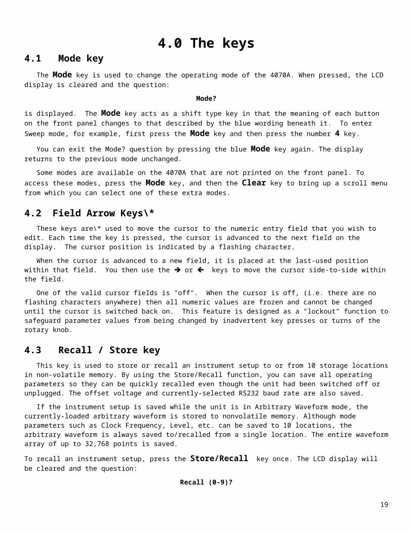
4.0 The keys4.1 Mode key The Mode key is used to change the operating mode of the 4070A. When pressed, the LCD display is cleared and the question:
Mode?
is displayed. The Mode key acts as a shift type key in that the meaning of each button on the front panel changes to that described by the blue wording beneath it. To enter Sweep mode, for example, first press the Mode key and then press the number 4 key.
You can exit the Mode? question by pressing the blue Mode key again. The display returns to the previous mode unchanged.
Some modes are available on the 4070A that are not printed on the front panel. To access these modes, press the Mode key, and then the Clear key to bring up a scroll menu from which you can select one of these extra modes. 4.2 Field Arrow Keys\* These keys are\* used to move the cursor to the numeric entry field that you wish to edit. Each time the key is pressed, the cursor is advanced to the next field on the display. The cursor position is indicated by a flashing character.
When the cursor is advanced to a new field, it is placed at the last-used position within that field. You then use the è or ç keys to move the cursor side-to-side within the field.
One of the valid cursor fields is "off". When the cursor is off, (i.e. there are no flashing characters anywhere) then all numeric values are frozen and cannot be changed until the cursor is switched back on. This feature is designed as a "lockout" function to safeguard parameter values from being changed by inadvertent key presses or turns of the rotary knob. 4.3 Recall / Store key This key is used to store or recall an instrument setup to or from 10 storage locations in non-volatile memory. By using the Store/Recall function, you can save all operating parameters so they can be quickly recalled even though the unit had been switched off or unplugged. The offset voltage and currently-selected RS232 baud rate are also saved.
If the instrument setup is saved while the unit is in Arbitrary Waveform mode, the currently-loaded arbitrary waveform is stored to nonvolatile memory. Although mode parameters such as Clock Frequency, Level, etc. can be saved to 10 locations, the arbitrary waveform is always saved to/recalled from a single location. The entire waveform array of up to 32,768 points is saved.
To recall an instrument setup, press the Store/Recall key once. The LCD display will be cleared and the question:
Recall (0-9)?
will appear, asking you to press a numeric key 0 to 9 to select one of ten available locations to use. You can abort this question without saving a configuration by pressing any key other than 0 to 9.
If you then press the 5 key, for example, the display will show
Configuration recalled from location 5
to confirm the recall operation. To save an instrument setup, press the Store/Recall button twice. The LCD display will be cleared and the question:
Store (0-9)? will appear, asking you to select one of ten available locations to store the configuration. You can abort the question without recalling a configuration by pressing any key other than 0 to 9.
Note: Location 0 is special. The instrument state stored to location 0 will be recalled on power-up. This includes the serial port baud rate.
11

4.4 Offset key The Offset key is used to specify a DC offset voltage to be added to the output signal. When this key is pressed, the LCD display is cleared and the cursor is placed in a numeric field to enter the offset voltage. Both positive and negative voltages can be entered.
To exit the offset entry screen and return to the current mode, press the Offset key again.
The offset voltage value can be entered in the same manner as any other numeric value. You can also use the wheel to modify a particular digit in the value. Any voltage within the range of -6.0 to +6.0 can be entered.
NOTE: The offset voltage specified is a 50 ohm LOADED value. This is the voltage that will appear across a 50 ohm load connected to the SIG Out connector. If you are connecting the output to a high impedance load, the output voltage will be twice that entered.
NOTE: Care must be taken when specifying an output offset voltage and level such that the output does not clip. The loaded output cannot swing higher than +6.0V or lower than -6.0V. Therefore:
│Offset voltage│ + 1/2 * Vp-p < 6.0 The 4070A can be used as a variable voltage source by setting the output frequency to 0.0 Hz while in Sinewave mode. Then set the offset voltage to the desired output voltage. Remember, the output impedance is 50 ohms. Up to +/- 70 mA can be drawn from the output under these conditions.
This key is also used to select the RS232 baud rate after the Mode key is pressed once. By pressing Mode then Offset, a menu of baud rates for the 4070A is presented. For more information, refer to the chapter on Remote Mode.
4.5 Trigger key The Trigger key is used in modes that require a trigger event to begin a process. Triggered Sweep mode uses this key to begin a sweep. Triggered Burst and Data Modulation modes also use this key to begin the generation of a burst signals. Arbitrary Waveform, Function Generator and Pulse Generator modes use this key to begin the generation of a waveform in Triggered mode.
In modes that require a trigger, the trigger can come from three sources:
1. Pressing the Trigger key 2. Applying a low-to-high transition on the Ext Trigger In connector 3. Sending an ASCII "T" to the RS232 port
The 4070A will simultaneously accept a trigger from all of the above sources.
4.6 Numeric keys ( 0 to 9, - and . )
The 0 to 9, - and . keys are used to enter a numeric value. These keys are used in the same manner as those on a calculator.
The - key is only accepted when entering numeric values that can be negative, i.e. dBm or offset values. The keypress is ignored otherwise.
In DTMF Generation mode, the . key is used to generate the star ("*") DTMF digit and the - key is used to generate the pound ("#") DTMF digit.
These keys are also used to select a mode after the Mode key is pressed once. These keys are then used to select a mode indicated by the blue text written beneath these keys.
12

4.7 é , ê , è, ç keys
The arrow keys are used to move the cursor and edit numeric values.
The è and ç keys move the cursor side to side within a cursor field. They can be used to position the cursor over a digit within the field to modify. Once the cursor is over the desired digit, use the é or ê key to increment or decrement that digit.
Pressing the é key increments the digit under the cursor and has the same effect as rotating the knob clockwise 1 tick. Pressing the ê key decrements the digit under the cursor and has the same effect as rotating the knob counter-clockwise 1 tick.
While a numeric value is being typed in, you can use the ç key as an erase key. Pressing this key erases the last digit entered, allowing you to correct typing mistakes.
All arrow keys have an "auto repeat" feature. By holding down the key, the key will repeat continuously until released. This makes it more convenient to quickly sweep a value or move the cursor within a field.
These keys are also used to select a new operating mode after the Mode key is pressed. The arrow keys are then used to select the mode indicated by the blue text beneath the key.
In DTMF Generation mode, these keys specify DTMF digits A,B,C,D which are signaling tones used in the telephone network but not found on a typical telephone. For more information, refer to the chapter on DTMF Generation mode.
4.8 Clear key While the cursor is within a numeric field, the Clear key erases all digits within the field, allowing the user to start over when entering a value. This key is also used to select the "Other" mode after the Mode key is pressed once. By selecting Other Mode, a menu of extended modes for the 4070A is presented. See the chapter on Changing Modes.
4.9 MHz/dBm, KHz/Vp-p/Sec, Hz/mVp-p/mS keys
These keys are used to select the units for a numeric value once it has been typed into a parameter field. After entering all digits for a value, you must press one of these keys to complete the entry of the value. In other words, these keys serve as an "enter" key since a value being edited in a cursor field is not accepted and processed until one of these keys is pressed. After pressing one of these keys, the 4070A will make a double clicking noise to indicate that the value has been accepted. If the entered value is outside the allowable range for the field, the 4070A will give an error beep and set the value to its upper or lower limit.
To enter a value in Volts or milliVolts, use the Vp-p and mVp-p keys, respectively.
When entering a value that has units not listed on the key (i.e. percentage, ohms, etc.), any one of these three keys will work as an enter key.
4.9 One Touch Mode Keys
These keys immediately switch the function generator to the operating mode indicated on the key. These keys make it more convenient to switch to frequently-used operating modes. \*
13

5.0 Mode Descriptions
The following pages describe each operating mode of the 4070A. The meaning of each parameter that appears on the LCD display is described in detail.
5.1 Basic Sinewave (CW) Mode
Introduction The Basic Sinewave (CW) mode generates a sinewave of fixed frequency and level. This mode is entered by pressing the Sinewave One Touch Mode Selection key\*.
NOTE: In this mode you can set the output frequency to 0 Hz and, by specifying an offset voltage, use the 4070A as a variable voltage source (with a 50 ohm output impedance). Up to +/- 70 mA can be drawn from the SIG Out output. Sinewave Mode Parameters
The Sinewave mode has the following front panel display: Figure 5.1-1: Sinewave mode display
Each parameter is described below:
1. Frequency
In this field enter the frequency of the sinusoid, from 0 Hz (DC) to 21.5000000 MHz in .01 Hz steps.
2. Level In this field enter the output level, from 4 mVp-p to 10 Vp-p in 1 mV steps or from -44.0 dBm to +24.0 dBm in .1 dBm steps. NOTE: The level specified is a 50 ohm LOADED level. This is the level of the signal which will appear across a 50 ohm load connected to the SIG Out connector. Into an open circuit, the output swing will be twice the value entered.
Offset By pressing this key, you can enter an offset voltage for the output waveform. For more information on output offsets refer to section 4.4.
Ext Gating Input (rear panel connector)
This TTL compatible input can be used to gate the output signal on or off. A logic high voltage on this jack (+3V to +10V) will turn off the output signal. A logic low voltage on this jack (0V to -10V) will leave the output signal on. For further information on the Ext Gating Input, refer to section 2.0.
14
Sinewave Mode20,000,000.00 MHz -10.0 dBm

5.2 Internal AM ModeIntroduction The Internal AM mode generates an amplitude modulated signal of fixed carrier frequency. An internally-generated sinusoid is used as a modulating signal to vary the amplitude of a carrier sinusoid. The modulation waveform is not suppressed carrier; i.e. a fixed amount of carrier power is always present in the modulated signal.
Internal AM Mode Parameters
The Internal AM mode has the following front panel display:
Figure 5.2-1: Internal AM mode display 1. Modulating Frequency In this field enter the frequency of the modulating sinusoid, from 0 Hz to 10,000 Hz in 1 Hz steps.
2. Percentage modulation
In this field enter the degree to which the modulating signal is allowed to change the carrier amplitude. You may enter from 0% (no change) to 100% (maximum change) in 1% steps.
To enter a value, type 1 to 3 numeric digits. If you type 3 digits, the value is automatically entered. If you only type 1 or 2 digits, you can press the MHz key or the KHz key or the Hz key (all are equivalent) to enter the percentage value. 3. Carrier Frequency In this field enter the frequency of the carrier, from 0 Hz (DC) to 21.5000000 MHz in .01 Hz steps.
4. PEP Level
In this field enter the output level, from 4 mVp-p to 10 Vp-p in 1 mV steps or from -44.0 dBm to +24.0 dBm in .1 dBm steps.
NOTE: The level specified in Internal AM mode is the Peak Envelope Power, or PEP. As a peak-to-peak value, this level represents the maximum peak-to-peak voltage swing that will result from a 100 percent modulated carrier. If no modulating signal were applied, the unmodulated carrier would have only half the peak-to-peak swing of a 100% modulated carrier.
NOTE: The level specified is a 50 ohm LOADED level. This is the level of the signal which will appear across a 50 ohm load connected to the SIG Out connector. Into an open circuit, the output swing will be twice the value entered.
Offset You can enter an offset voltage for the output waveform. For more information on output offsets refer to section 4.4.
Ext Gating Input (rear panel connector) This TTL compatible input can be used to gate the output signal on or off. A logic high level turns off the output. For further information on the Ext Gating Input, refer to section 2.0.
15
Int AM: 1,000 Hz Percent Mod: 100%20,000,000.00 MHz PEP level: -10.0 dBm

5.3 External AM ModeIntroduction The External AM mode generates an amplitude modulated signal of fixed carrier frequency. An externally-supplied signal on the Ext Mod In connector is used as a modulating signal to vary the amplitude of a carrier sinusoid. The modulation waveform is not suppressed carrier; i.e. a fixed amount of carrier power is always present in the modulated signal. External AM Mode Parameters The External AM mode has the following front panel display:
Figure 5.3-1: External AM mode display 1. Input Gain In this field specify a value used to scale the input signal. With a value of .999, a 1 Vp-p signal on the input will result in 100% modulation of the carrier amplitude. You may enter a value from 0 to .999. (The gain value is always less than 1.0).
To enter a value, type 1 to 3 numeric digits. If you type 3 digits, the value is automatically entered. If you only type 1 or 2 digits, you can press the MHz key or the KHz key or the Hz key (all are equivalent) to enter the gain value. 2. Carrier Frequency In this field enter the frequency of the carrier, from 0 Hz (DC) to 21.5000000 MHz in .01 Hz steps.
3. PEP Level
In this field enter the output level, from 4 mVp-p to 10 Vp-p in 1 mV steps or from -44.0 dBm to +24.0 dBm in .1 dBm steps.
NOTE: The level specified in External AM mode is the Peak Envelope Power, or PEP. As a peak-to-peak value, this level represents the maximum peak-to-peak voltage swing that will result from a 100 percent modulated carrier. If no modulating signal were applied, the unmodulated carrier would have only half the peak-to-peak swing of a 100% modulated carrier.
NOTE: The level specified is a 50 ohm LOADED level. This is the level of the signal which will appear across a 50 ohm load connected to the SIG Out connector. Into an open circuit, the output swing will be twice the value entered.
Offset You can enter an offset voltage for the output waveform. For more information on output offsets refer to section 4.4.
Ext Gating Input (rear panel connector) This TTL compatible input can be used to gate the output signal on or off. A logic high voltage turns off the output. For further information on the Ext Gating Input, refer to section 2.0.
16
External AM Input gain: .99920,000,000.00 MHz PEP level: -10.0 dBm

5.4 Internal FM ModeIntroduction
The Internal FM mode generates a frequency modulated signal of fixed amplitude. An internally-generated sinusoid is used as a modulating signal to vary the frequency of a carrier sinusoid.
Internal FM Mode Parameters The Internal FM mode has the following front panel display:
Figure 5.4-1: Internal FM mode display 1. Modulating Frequency
In this field enter the frequency of the modulating sinusoid. You may enter from 0 Hz to 10,000 Hz in 1 Hz steps.
2. Peak Frequency Deviation In this field specify the degree to which the modulating signal is allowed to change the carrier frequency. You may enter from 0 Hz (no change) to 5.0 MHz in 1 Hz steps
This parameter is a peak value. If the deviation were 1 KHz and the carrier frequency were 1 MHz, for example, then the output frequency will swing between a maximum of 1 MHz + 1 KHz and a minimum of 1 MHz - 1 KHz. Note: If values for the deviation and carrier frequencies are entered such that the output frequency exceeds the 0 to 21.5 MHz range, distortion of the output waveform may result. 3. Carrier Frequency
In this field enter the frequency of the carrier. You may enter from 0 Hz (DC) to 21.5000000 MHz in .01 Hz steps.
Note: If values for the deviation and carrier frequencies are entered such that the output frequency exceeds the 0 to 21.5 MHz range, distortion of the output waveform may result.
4. Level
In this field enter the output level, from 4 mVp-p to 10 Vp-p in 1 mV steps or from -44.0 dBm to +24.0 dBm in .1 dBm steps.
NOTE: The level specified is a 50 ohm LOADED level. This is the level of the signal which will appear across a 50 ohm load connected to the SIG Out connector. Into an open circuit, the output swing will be twice the value entered.
Offset You can enter an offset voltage for the output waveform. For more information on output offsets refer to section 4.4.
Ext Gating Input (rear panel connector) This TTL compatible input can be used to gate the output signal on or off. A logic high voltage turns off the output. For further information on the Ext Gating Input, refer to section 2.0.
17
Int FM: 1,000 Hz Pk dev: 10,000 Hz20,000,000.00 MHz -10.0 dBm

5.5 External FM ModeIntroduction
The External FM mode generates a frequency modulated signal of fixed amplitude. An externally supplied signal on the Ext Mod In connector is used to vary the frequency of a carrier sinusoid. External FM Mode Parameters
The External FM mode has the following front panel display:
Figure 5.4-1: External FM mode display 1. Peak Frequency Deviation
In this field specify the degree to which the modulating signal is allowed to change the carrier frequency. You may enter from 0 Hz (no change) to 5.0 MHz in 1 Hz steps
This parameter is a peak value. If the deviation were 1 KHz and the carrier frequency were 1 MHz, for example, then the output frequency will swing between a maximum of 1 MHz + 1 KHz and a minimum of 1 MHz - 1 KHz for an input signal level of 1 Vp-p.
Note: If values for the deviation and carrier frequencies are entered such that the output frequency exceeds the 0 to 21.5 MHz range, distortion of the output waveform may result. 2. Carrier Frequency In this field enter the frequency of the carrier. You may enter from 0 Hz (DC) to 21.5000000 MHz in .01 Hz steps.
Note: If values for the deviation and carrier frequencies are entered such that the output frequency exceeds the 0 to 21.5 MHz range, distortion of the output waveform may result. 3. Level
In this field enter the output level, from 4 mVp-p to 10 Vp-p in 1 mV steps or from -44.0 dBm to +24.0 dBm in .1 dBm steps.
NOTE: The level specified is a 50 ohm LOADED level. This is the level of the signal which will appear across a 50 ohm load connected to the SIG Out connector. Into an open circuit, the output swing will be twice the value entered.
Offset You can enter an offset voltage for the output waveform. For more information on output offsets refer to section 4.4.
Ext Gating Input (rear panel connector)
This TTL compatible input can be used to gate the output signal on or off. A logic high voltage turns off the output. For further information on the Ext Gating Input, refer to section 2.0.
18
External FM Pk dev: 10,000 Hz20,000,000.00 MHz -10.0 dBm

5.6 Internal PM ModeIntroduction
The Internal PM mode generates a phase modulated signal of fixed amplitude. An internally-generated sinusoid is used as a modulating signal to vary the phase of a carrier sinusoid.
Internal PM Mode Parameters The Internal PM mode has the following front panel display:
Figure 5.6-1: Internal PM mode display 1. Modulating Frequency
In this field enter the frequency of the modulating sinusoid. You may enter from 0 Hz to 10,000 Hz in 1 Hz steps.
2. Peak Phase Deviation
In this field specify the degree to which the modulating signal is allowed to change the carrier phase. You may enter from 0 (no change) to 180 degrees in 1 degree steps.
This parameter is a peak value. If the deviation value were 180 degrees, for example, then the output phase will advance to a maximum of +180 degrees and retard to a minimum of -180 degrees.
To enter a value, type 1 to 3 numeric digits. If you type 3 digits, the value is automatically entered. If you only type 1 or 2 digits, you can press the MHz key or the KHz key or the Hz key (all are equivalent) to enter the degree value.
Note: FM modulation is equivalent to PM for small frequency deviation values. If you need a larger phase deviation than 180 degrees, go to FM mode and specify an appropriate peak frequency deviation value.
3. Carrier Frequency
In this field enter the frequency of the carrier. You may enter from 0 Hz (DC) to 21.5000000 MHz in .01 Hz steps.
4. Level
In this field enter the output level, from 4 mVp-p to 10 Vp-p in 1 mV steps or from -44.0 dBm to +24.0 dBm in .1 dBm steps.
NOTE: The level specified is a 50 ohm LOADED level. This is the level of the signal which will appear across a 50 ohm load connected to the SIG Out connector. Into an open circuit, the output swing will be twice the value entered.
Offset You can enter an offset voltage for the output waveform. For more information on output offsets refer to section 4.4.
Ext Gating Input (rear panel connector)
This TTL compatible input can be used to gate the output signal on or off. A logic high voltage turns off the output. For further information on the Ext Gating Input, refer to section 2.0.
19
Int PM: 1,000 Hz Pk dev: 180 deg20,000,000.00 MHz -10.0 dBm

5.7 External PM ModeIntroduction
The External PM mode generates a phase modulated signal of fixed amplitude. An externally supplied signal on the Ext Mod In connector is used to vary the phase of a carrier sinusoid. External PM Mode Parameters The External PM mode has the following front panel display:
Figure 5.7-1: External PM mode display 1. Peak Phase Deviation
In this field specify the degree to which the modulating signal is allowed to change the carrier phase. You may enter from 0 degrees (no change) to 180 degrees in 1 degree steps.
This parameter is a peak value. If the deviation value were 180 degrees, for example, then the output phase will advance to a maximum of +180 degrees and retard to a minimum of -180 degrees for a 1 Vp-p input signal.
To enter a value, type 1 to 3 numeric digits. If you type 3 digits, the value is automatically entered. If you only type 1 or 2 digits, you can press the MHz key or the KHz key or the Hz key (all are equivalent) to enter the phase deviation value.
Note: FM modulation is equivalent to PM for small frequency deviation values. If you need a larger phase deviation than 180 degrees, go to FM mode and specify an appropriate peak frequency deviation value. 2. Carrier Frequency
In this field enter the frequency of the carrier. You may enter from 0 Hz (DC) to 21.5000000 MHz in .01 Hz steps.
3. Level In this field enter the output level, from 4 mVp-p to 10 Vp-p in 1 mV steps or from -44.0 dBm to +24.0 dBm in .1 dBm steps.
NOTE: The level specified is a 50 ohm LOADED level. This is the level of the signal which will appear across a 50 ohm load connected to the SIG Out connector. Into an open circuit, the output swing will be twice the value entered.
Offset You can enter an offset voltage for the output waveform. For more information on output offsets refer to section 4.4.
Ext Gating Input (rear panel connector) This TTL compatible input can be used to gate the output signal on or off. A logic high voltage turns off the output. For further information on the Ext Gating Input, refer to section 2.0.
20
External PM Pk dev: 180 deg20,000,000.00 MHz -10.0 dBm

5.8 Sweep ModeIntroduction
The Sweep mode continuously changes the frequency of a fixed amplitude sinusoid between a specified start frequency and a specified stop frequency. The user can specify how long it takes for the sweep to reach the stop frequency. The frequency may be stepped between the start and stop frequency linearly (i.e. the frequency is incremented over time by a constant value) or a logarithmically (where the frequency is advanced logarithmically over time). A sweep direction (up or down) may also be specified.
The user can specify a Continuous or Triggered type sweep. In the Continuous mode, the sweep is restarted once the stop frequency is reached. In the Triggered mode, the output waits at the start frequency until a trigger condition happens (Triggers can come from a front panel keypress, a rising edge on the EXT Trigger connector, or an ASCII "T" on the terminal port). Once a trigger occurs, the output frequency is swept to the stop frequency and the sweep is then reset to the start frequency. The unit then awaits another trigger condition. For downward sweeps, the output frequency begins at the stop frequency and ends at the start frequency.
Sweep Mode Parameters The Sweep mode has the following front panel display:
Figure 5.8-1: Sweep mode display
1. Start Frequency In this field enter the starting frequency for the sweep. You may enter from 0 Hz (DC) to 21.5000000 MHz in .01 Hz steps.
NOTE: You are not allowed to enter a start frequency that is greater than the stop frequency. 2. Stop Frequency In this field enter the ending frequency for the sweep. You may enter from 0 Hz to 21.5000000 MHz in .01 Hz steps.
NOTE: You are not allowed to enter a stop frequency that is less than the start frequency. 3. Linear / Log sweep In this field select how the sweep frequency is incremented during the sweep. A linear sweep means that the frequency is incremented by a constant amount for a given amount of time. A log sweep means that the frequency is adjusted logarithmically between the start and stop frequencies as the sweep progresses.
To set Linear type sweep, press 1. To set Log type sweep, press 0. Pressing any arrow key or rotating the wheel will toggle the sweep type between Linear and Log.
21
St: 1,000,000.00 Hz Stp: 20,000,000.00 HzLinear | Cont | Up | Time: 60,000 mS -10.0 dBm
4. Continuous / Triggered sweep In this field select whether the sweep is performed continuously or on a single event basis. If you select a Continuous sweep, then the sweep is immediately restarted once the stop frequency is reached. If you select a Triggered type sweep, then the sweep is halted once the stop frequency is reached. The sweep is not restarted again until another trigger occurs. The trigger can come from three sources:
1. Pressing the Trigger key 2. Applying a low-to-high transition on the Ext Trig In connector 3. Sending an ASCII "T" to the RS232 port
The 4070A will simultaneously accept a trigger from all of the above sources.
To set Continuous type sweep, press 1. To set Triggered type sweep, press 0. Pressing any arrow key or rotating the wheel will toggle the sweep type between Continuous and Triggered.
5. Up / Down sweep
In this field select the direction of the sweep. An up sweep begins at the start frequency and ends at the end frequency. A down sweep begins at the end frequency and ends at the start frequency.
To set Up type sweep, press 0. To set Down type sweep, press 1. Pressing any arrow key or rotating the wheel will toggle the sweep between Up and Down.
6. Sweep time
In this field you specify how long it takes the sweep to increase the frequency from the start frequency to the stop frequency. You may enter 1 mS to 60,000 mS (60 seconds) in 1 mS steps.
In Continuous sweep mode, the sweep may be halted by applying a logic high to the Ext Gating Input connector on the rear of the unit. Doing so also halts the sweep timer, i.e. the sweep time will be lengthened by the amount of time that the sweep is halted. 7. Level In this field enter the output level, from 4 mVp-p to 10 Vp-p in 1 mV steps or from -44.0 dBm to +24.0 dBm in .1 dBm steps. NOTE: The level specified is a 50 ohm LOADED level. This is the level of the signal which will appear across a 50 ohm load connected to the SIG Out connector. Into an open circuit, the output swing will be twice the value entered. OffsetYou can enter an offset voltage for the output waveform. For more information on output offsets refer to section 4.4.
SYNC Out Connector (front panel) This TTL/CMOS compatible output supplies a high going pulse at the start of each sweep. Useful for triggering scopes or other equipment at the start of each sweep.
Ext Gating In Connector (rear panel connector) This TTL compatible input is used in two different ways, depending on whether the sweep mode is Continuous or Triggered.
In Continuous sweep, the user can halt the sweep "dead in its tracks" by applying a logic high (+3V to +10V) on this jack. The output frequency will be held constant until the input is brought low again. The sweep will then resume toward the stop frequency.
In Triggered type sweep, this input functions as an external sweep trigger input. A logic low-to-high transition on this input will trigger the sweep.
This input has an internal pulldown resistor so that the input is held at a logic low when this input is left unconnected.
22

5.9 Internal FSK ModeIntroduction
The Internal FSK mode generates a frequency shift keyed signal of fixed amplitude. An internal timer is used as a modulating signal to toggle the output frequency between the Mark frequency and the Space frequency at a specified rate.
Internal FSK Mode Parameters The Internal FSK mode has the following front panel display:
Figure 5.9-1: Internal FSK mode display 1. Modulating Frequency
In this field enter the frequency at which the output will switch between the Mark and Space frequencies. You may enter from 0 Hz to 130,000 Hz in 1 Hz steps.
The internal modulating frequency is accurate to 1 Hz from 0 Hz to 3900 Hz. It is accurate to within 1% across its full range of 0 Hz to 130,000 Hz.
2. Mark Frequency In this field enter the Mark frequency, from 0 Hz (DC) to 21.5000000 MHz in .01 Hz steps.
3. Space Frequency In this field enter the Space frequency, from 0 Hz (DC) to 21.5000000 MHz in .01 Hz steps.
4. Level
In this field enter the output level, from 4 mVp-p to 10 Vp-p in 1 mV steps or from -44.0 dBm to +24.0 dBm in .1 dBm steps.
NOTE: For wideband FSK (where the difference between Mark and Space frequencies is > 1.0 MHz), the output level may shift slightly between the mark and space frequencies. The 4070A has internal leveling circuitry which is disabled in this mode, in order to offer higher FSK modulation rates.
NOTE: The level specified is a 50 ohm LOADED level. This is the level of the signal which will appear across a 50 ohm load connected to the SIG Out connector. Into an open circuit, the output swing will be twice the value entered. Offset You can enter an offset voltage for the output waveform. For more information on output offsets refer to section 4.4.
Ext Gating Input (rear panel connector)
This TTL compatible input can be used to gate the output signal on or off. A logic high voltage turns off the output. For further information on the Ext Gating Input, refer to section 2.0.
23
Int FSK: 1,000 Hz Mark: 1,000,000.00 HzSpace: 2,000,000.00 Hz -10.0 dBm

5.10 External FSK ModeIntroduction
The External FSK mode generates a frequency shift keyed signal of fixed amplitude. An external digital input signal is used as a modulating signal to shift the output frequency between the Mark frequency and the Space frequency.
External FSK Mode Parameters The External FSK mode has the following front panel display:
Figure 5.10-1: External FSK mode display
1. Mark Frequency
In this field enter the Mark frequency, from 0 Hz (DC) to 21.5000000 MHz in .01 Hz steps.
When the voltage on the Ext FSK In connector is high (+3V to +10V), the output frequency will be set to this value. 2. Space Frequency
In this field enter the Space frequency, from 0 Hz (DC) to 21.5000000 MHz in .01 Hz steps.
When the voltage on the Ext FSK In connector is low (0V to -10V), the output frequency will be set to this value. 3. Level In this field enter the output level, from 4 mVp-p to 10 Vp-p in 1 mV steps or from -44.0 dBm to +24.0 dBm in .1 dBm steps. NOTE: For wideband FSK (where the difference between Mark and Space frequencies is > 1.0 MHz), the output level may shift slightly between the mark and space frequencies. The 4070A has internal leveling circuitry which is disabled in this mode, in order to offer faster FSK switching rates. NOTE: The level specified is a 50 ohm LOADED level. This is the level of the signal which will appear across a 50 ohm load connected to the SIG Out connector. Into an open circuit, the output swing will be twice the value entered. Offset By pressing this key, you may enter an offset voltage for the output waveform. For more information on output offsets refer to section 4.4.
Ext FSK Input (rear panel connector)
Apply the digital data to be modulated to this connector. When this input is high, the output frequency is set to the Mark value. When this input is low, the output frequency is set to the Space value. For more information on this input refer to chapter 2.0.
24
Ext FSK: Mark: 1,000,000.00 HzSpace: 2,000,000.00 Hz -10.0 dBm

5.11 Burst ModeThe Burst mode generates a sinusoid burst of fixed frequency and level for a specified duration. Both continuous and triggered bursts may be generated.
In the continuous burst mode, the 4070A continuously gates the output sinusoid on and off according to the values entered in the On and Off fields.
In triggered burst mode, the output frequency is set to 0 Hz and the unit awaits a trigger condition. When a trigger condition occurs, the 4070A delays for a time specified in the Off time field and then sets the output frequency to the specified value. When the time specified in the On field has elapsed, the 4070A resets the output frequency to 0 Hz and awaits another trigger condition.
The trigger can come from three sources: 1. Pressing the Trigger key 2. Applying a low-to-high transition on the Ext Trig In connector 3. Sending an ASCII "T" to the RS232 port
The 4070A will simultaneously accept a trigger from all of the above sources.
Tip: An external digital signal can be used to generate bursts by switching to Sinewave mode and using the Ext. Gating In connector to gate the output waveform on or off. The output is turned off when the input is at a logic high voltage (3V to 10V). This input can be run up to 3 MHz.
Figure 5.11-1: Burst mode display1. Continuous / Triggered Mode This field selects whether the bursts will be generated on an ongoing or single event basis. To select Triggered mode, press 0. To select Continuous mode, press 1. Pressing any arrow key or rotating the wheel will toggle this value.
2. Burst On Time (Duration) The burst will last for the duration specified in this field before being switched off. You may enter a value from 1 mS to 99,999 mS in 1 mS steps.
3. Burst frequency The output frequency is held at this value during the burst. You may enter from 0 Hz (DC) to 21.5000000 MHz in .01 Hz steps.
4. Burst Off Time (Delay) The burst waveform will be held at 0V for the duration in this field before the sinewave is switched on. In triggered burst mode this value may be viewed as a delay between the trigger event and when the output sinusoid is generated. You may enter a value from 0 mS to 99,999 mS in 1 mS steps.
5. Level In this field enter the 50 ohm loaded output level, from 4 mVp-p to 10 Vp-p or from -44.0 dBm to +24.0 dBm.
Offset You can enter an offset voltage for the output waveform. For more information on refer to section 4.4.
Ext Gating Input (rear panel connector) In triggered burst mode this input functions as an external trigger input. A logic low-to-high transition on this input will trigger the burst. This input has an internal pulldown resistor so that the input is held at a logic low when this input is left unconnected. See section 2.0 for more information.
25
Burst Mode Trig Duration: 10,000 mS20,000,000.00 Hz Dly: 5,000 mS -10.0 dBm

5.12 Internal SSB ModeIntroduction The Internal SSB mode generates a Single SideBand (SSB) modulated signal of fixed carrier frequency. An internally generated sinusoid is used as a modulating signal to modulate either the upper or lower sideband of a carrier sinusoid. The modulation waveform is suppressed carrier, i.e. no carrier energy is present in the modulated signal.
Internal SSB Mode Parameters The Internal SSB mode has the following front panel display:
Figure 5.12-1: Internal SSB mode display1. Modulating Frequency
In this field enter the frequency of the modulating sinusoid. You may enter from 0 Hz to 1 MHz in 1 Hz steps.
Note: It is possible to enter values for the modulating and carrier frequencies such that the upper sideband can exceed 21.5 MHz or the lower sideband can go below 0 Hz. Care should be taken not to do this since distortion of the output waveform will result. 2. Upper/Lower Sideband selection
This parameter selects which sideband will be generated. Single sideband modulation specifies that all energy in the modulated waveform should be either above the carrier frequency or below it. Upper sideband places all signal energy above the carrier frequency, and Lower sideband places all signal energy below the carrier frequency.
To select Lower sideband, press 0. To select Upper sideband, press 1. Pressing any arrow key or rotating the wheel will toggle the sideband selection between Upper and Lower. 3. Carrier Frequency
In this field enter the frequency of the carrier. You may enter from 0 Hz (DC) to 21.5000000 MHz in .01 Hz steps.
Note: It is possible to enter values for the modulating and carrier frequencies such that the upper sideband can exceed 21.5 MHz or the lower sideband can go below 0 Hz. Care should be taken not to do this since distortion of the output waveform may result.
4. Level
In this field enter the output level, from 4 mVp-p to 10 Vp-p in 1 mV steps or from -44.0 dBm to +24.0 dBm in .1 dBm steps.
NOTE: The level specified is a 50 ohm LOADED level. This is the level of the signal which will appear across a 50 ohm load connected to the SIG Out connector. Into an open circuit, the output swing will be twice the value entered.
Offset You can enter an offset voltage for the output waveform. For more information on output offsets refer to section 4.4.
Ext Gating Input (rear panel connector) This TTL compatible input can be used to gate the output signal on or off. A logic high voltage turns off the output. For further information on the Ext Gating Input, refer to section 2.0.
26
Int SSB: 1,000 Hz Upper Sideband20,000,000.00 Hz -10.0 dBm

5.13 External SSB ModeIntroduction The External SSB mode generates a Single SideBand (SSB) modulated signal of fixed carrier frequency. An externally supplied signal on the Ext Mod In connector is used to modulate either the upper or lower sideband of a carrier sinusoid. The modulation waveform is suppressed carrier, i.e. little carrier energy is present in the modulated signal.
External SSB Mode Parameters The External SSB mode has the following front panel display:
Figure 5.13-1: External SSB mode display
1. Upper/Lower Sideband selection
This parameter selects which sideband will be generated. Single sideband modulation specifies that all energy in the modulated waveform should be either above the carrier frequency or below it. Upper sideband places all signal energy above the carrier frequency, and Lower sideband places all signal energy below the carrier frequency. To select Lower sideband, press 0. To select Upper sideband, press 1. Pressing any arrow key or rotating the wheel will toggle the sideband selection between Upper and Lower.
2. Carrier Frequency
In this field enter the frequency of the carrier. You may enter from 0 Hz (DC) to 21.5000000 MHz in .01 Hz steps.
Note: It is possible to enter values for the carrier frequency such that the upper sideband can exceed 21.5 MHz or the lower sideband can go below 0 Hz. Care should be taken not to do this since distortion of the output waveform may result. 3. Level
In this field enter the output level, from 4 mVp-p to 10 Vp-p in 1 mV steps or from -44.0 dBm to +21.0 dBm in .1 dBm steps.
NOTE: The level specified is a 50 ohm LOADED level. This is the level of the signal which will appear across a 50 ohm load connected to the SIG Out connector. Into an open circuit, the output swing will be twice the value entered.
Offset You can enter an offset voltage for the output waveform. For more information on output offsets refer to section 4.4.
Ext Gating Input (rear panel connector)
This TTL compatible input can be used to gate the output signal on or off. A logic high voltage turns off the output. For further information on the Ext Gating Input, refer to section 2.0.
27
Ext SSB Upper Sideband20,000,000.00 Hz -10.0 dBm

5.16 DTMF Generation ModeIntroduction
The DTMF (Dual Tone Multi Frequency) Generation mode generates the Touch-tone dialing tones for the American telephone network. The user can specify dialing digits "0" to "9", "", "#" as well as the extra DTMF digits "A" through "D". A start delay can be specified for each digit. The duration of each digit can also be specified. These two parameters make it possible to test the performance DTMF detection systems. By sending a string of digits to dial to the RS232 port, the 4070A can be used as a speed dialer; these digits are queued and dialed with the specified duration and delay between digits.
Note: The 4070A can generate a single DTMF digit on a repetitive basis by switching to Dualtone Generation mode and setting each dualtone frequency to that of the desired DTMF digit. The ON and OFF times can then be set to repetitively generate the digit for the desired duration and repetition rate. Refer to the chapter on Dualtone Generation mode for more information.
Background
A DTMF dialing tone consists of two sinusoids of different frequencies which are added together to form the output waveform. These frequencies were chosen so that they are not harmonically related. The table below lists each dialing digit and its associated dualtone frequencies:
DTMF 0: 941 Hz and 1336 Hz DTMF 1: 697 Hz and 1209 Hz DTMF 2: 697 Hz and 1336 Hz DTMF 3: 697 Hz and 1477 Hz DTMF 4: 770 Hz and 1209 Hz DTMF 5: 770 Hz and 1336 Hz DTMF 6: 770 Hz and 1477 Hz DTMF 7: 852 Hz and 1209 Hz DTMF 8: 852 Hz and 1336 Hz DTMF 9: 852 Hz and 1477 Hz DTMF : 941 Hz and 1209 Hz DTMF #: 941 Hz and 1477 Hz DTMF A: 697 Hz and 1633 Hz DTMF B: 770 Hz and 1633 Hz DTMF C: 852 Hz and 1633 Hz DTMF D: 941 Hz and 1633 Hz
28

DTMF Generation Mode ParametersThe DTMF Generation mode has the following front panel display:
Figure 5.16-1: DTMF Generation mode display1. Generated DTMF Digit The last DTMF digit that was generated is displayed in this field. To generate a DTMF digit, the cursor must be either in this field or the OFF position. If the cursor is in any other field (i.e. Delay or Duration fields) then the keypad functions to enter those parameters.
Several keys on the front panel are used to generate DTMF digits other than “0” to “9”. They are listed here:
To generate the "#" DTMF digit, press the minus (-) key. To generate the "" DTMF digit, press the period (.) key. To generate the "A" DTMF digit, press the é key. To generate the "B" DTMF digit, press the ê key. To generate the "C" DTMF digit, press the è key. To generate the "D" DTMF digit, press the ç key.
2. DTMF Duration The DTMF tone will remain on for the time specified in this field. You may enter a value from 1 mS to 10,000 mS (10 seconds) in 1 mS steps. 3. DTMF Delay The 4070A will delay generation of the DTMF tone by the time specified in this field. This parameter is used primarily to add an inter-digit delay between dialed digits so that the user can send a string of ASCII digits to the RS232 port for speed dialing. The 4070A will insert the specified delay between the dialed digits. You may enter a value from 0 mS to 10,000 mS (10 seconds) in 1 mS steps. 4. Level
In this field enter the output level, from 4 mVp-p to 10 Vp-p in 1 mV steps or from -44.0 dBm to +21.0 dBm in .1 dBm steps.
NOTE: The level specified is a 50 ohm LOADED level. This is the level of the signal which will appear across a 50 ohm load connected to the SIG Out connector. Into an open circuit, the output swing will be twice the value entered.
Offset You can enter an offset voltage for the output waveform. For more information on output offsets refer to section 4.4.
Ext Gating Input (rear panel connector)
This TTL compatible input can be used to gate the output signal on or off. A logic high voltage turns off the output. For further information on the Ext Gating Input, refer to section 2.0.
29
DTMF generation: # Duration: 200 mSDelay: 1,000 mS Level: -10.0 dBm

5.17 DTMF Detection ModeIntroduction
The DTMF (Dual Tone Multi Frequency) Detection mode decodes and displays the Touch-tone dialing tones for the American telephone network. Signals to be decoded are applied to the External Mod In jack. Once a DTMF digit has been detected, it will appear on the LCD display and will also be sent to the RS232 terminal port. The input signal must be 10 Vp-p or less. If the input signal exceeds 10 Vp-p, the waveform will distort and adversely affect the DTMF detector. Input levels above 50 Vp-p may damage the 4070A. The DTMF detector in the 4070A features an AGC algorithm which boosts low level signals (20 mVp-p or greater) to detect low level DTMF tones.
For reliable detection, each DTMF digit must be present for a minimum of 100 mS. There must also be a minimum silent period of 100 mS between each DTMF digit.
The Ext Mod In input is high impedance (about 30K ohms). If your system expects this signal to be terminated, place a resistor (of the appropriate terminating resistance) across this input.
*** Caution ***
Do NOT connect the Ext. Mod In input directly to a telephone line. High voltages exist on a telephone line which will cause permanent damage to the 4070A. See appendix A for a suitable telephone line interface.
Background
Each DTMF dialing tone consists of two sinusoids of different frequencies which are added together to form the output waveform. These frequencies were chosen so that they are not harmonically related. The table below lists each dialing digit and its associated dualtone frequencies:
DTMF 0: 941 Hz and 1336 Hz DTMF 1: 697 Hz and 1209 Hz DTMF 2: 697 Hz and 1336 Hz DTMF 3: 697 Hz and 1477 Hz DTMF 4: 770 Hz and 1209 Hz DTMF 5: 770 Hz and 1336 Hz DTMF 6: 770 Hz and 1477 Hz DTMF 7: 852 Hz and 1209 Hz DTMF 8: 852 Hz and 1336 Hz DTMF 9: 852 Hz and 1477 Hz DTMF : 941 Hz and 1209 Hz DTMF #: 941 Hz and 1477 Hz DTMF A: 697 Hz and 1633 Hz DTMF B: 770 Hz and 1633 Hz DTMF C: 852 Hz and 1633 Hz DTMF D: 941 Hz and 1633 Hz
30

DTMF Detection Mode Parameters
The DTMF Detection mode has the following front panel display:
Figure 5.17-1: DTMF Detection mode display 1. DTMF Detected Digits All detected digits appear on this line of the display. The display shows up to 40 detected digits.When the 41st digit is detected, this line of the display is cleared and the new digit is printed on the left hand side.
All detected digits are sent to the terminal port. By connecting a computer to the terminal port, the 4070A can be used as a DTMF detection peripheral. See the example program in Appendix A.
2. RS232 Port
All DTMF detections are printed to the terminal port. When a DTMF digit is detected (the digit 6 is given here as an example), a carriage return and a linefeed plus the following text is sent to the terminal:
DTMF: 6
31
DTMF detection on Ext Mod input:1 2 3 # A 4

5.18 Power & Voltage Measurement ModeIntroduction The Power & Voltage Measurement mode measures the signal level on the Ext Mod In connector and displays the power and voltage level on the LCD display.
The Power Measurement mode applies to frequencies in the DC to 50 KHz range. All signals outside this frequency range are attenuated by an internal lowpass filter. A point-by-point true RMS power is calculated by the internal Digital Signal Processor (DSP). For the voltage measurement, an averaging (low pass filter) algorithm is used.
To calculate power, a "system impedance" must be specified. If the input signal were to be applied across a load resistor then that resistor would dissipate power. The power dissipated in the resistor is a function of the resistor's value. The value of this load resistor is referred to here as the "system impedance" which must be specified by the user. As opposed to instruments which use a fixed value for this impedance (i.e. 50 or 600 ohms) the 4070A allows any value from 1 to 999 ohms to be used for power calculations.
The Ext Mod In jack is high impedance (about 30 K ohms). If your system expects this signal to be terminated, place a resistor (of the appropriate terminating resistance) across this input.
Power & Voltage Measurement Mode Parameters
Figure 5.18-1: Power & Voltage Measurement mode display1. Power Level In this field the true RMS power level is displayed with .1 dBm resolution. The calculated power level is calculated using the RMS input voltage and the specified system impedance.
2. Voltage Level In this field the average DC voltage of the input signal is displayed. If an AC signal is applied to the input, this field will display the DC component of that signal.
3. System Impedance In this field specify the value of the load resistance used to calculate power. You may enter a value between 1 and 999 ohms.
To enter a value, type 1 to 3 numeric digits. If you type 3 digits, the value is automatically entered. If you only type 1 or 2 digits, you can press the MHz key or the KHz key or the Hz key (all are equivalent) to enter the impedance value.
4. External Modulation In Connector (rear panel)
Apply the signal to be measured to this connector. For this mode, the input signal may be in the -5.0V to +5.0V range. Levels outside this range will be clipped by limiting circuitry. *** Caution: Levels outside -25V to +25V may damage the 4070A.
5. RS232 PortYou can have the power level value continuously sent to the terminal port by issuing the remote control command "enable LCD echo." See chapter 6.0 for further details on this command.
32
Detected Level on mod input: -23.5 dBmVolts: 1,652 mV System impedance: 600 ohm

5.19 Arbitrary Mode The Arbitrary Mode lets the user design custom waveforms on a PC and download them to the 4070A for generation. The Arbitrary Waveform System is used to implement the Function Generator and Pulse Generator.
For complete details on the Arbitrary Mode, refer to section 7.0 of this manual.
33

5.20 Remote Mode This menu permits the user to specify the RS232 baud rate or to disable the port.
It might be useful to disable the port when you have a device connected to the RS232 port and you do not want characters that it may send to the 4070A to affect the operation of the unit.
The Remote Mode displays the menu:
RS-232 baud rate: 9600Use 0-9, arrow keys, or knob to select
You may scroll through a list of the available baud rates by rotating the wheel or pressing an arrow key. You may also specify a particular baud rate directly by pressing a number key according to the table below:
0 - Disable the RS232 port1 - 3002 - 12003 - 24004 - 48005 - 96006 - 192007 - 384008 - 576009 - 115200
To abort this question without affecting the current setting, press any key other a number or an arrow.
Disabling the serial port causes the 4070A to ignore all incoming characters from the serial port. Disabling the RS232 port does not affect the output of information, i.e. the 4070A will still output characters to the RS232 port.
Note: The baud rate is not permanently changed unless the instrument setup is saved using the RECALL/STORE key. On power-up, the instrument setup is recalled from location 0. You may therefore change the power-up baud rate of the instrument by selecting a baud rate and then saving the instrument setup to location 0.
This menu does not change any other RS232 parameters. The port is always set to 1 start bit, 8 data bits, 1 stop bit, and no parity.
*** For information on remote control operation of the 4070A, refer to chapter 6.0 “Remote Operation.”
34

5.21 Other Mode This mode displays a menu of extended modes that are available on the 4070A. It is used to present additional operating modes that are not printed on the front keypad.
The Other Mode menu is accessed by pressing the blue Mode key once and then the Clear key. The user is then presented with the following menu on the LCD display:
Select Mode: 1. BPSK < > to scroll 2. Dualtone
You can scroll through the list of available selections using the arrow keys. The ê or è key scrolls the display to higher selection numbers and the é or ç key scrolls the menu to lower selection numbers. You may also turn the wheel to scroll the menu forward or backward.
To select a mode listed in the menu, press its number key.
To abort the menu and return to the previous mode, press any key other than an arrow or 0 to 9.
35

5.22 Internal BPSK ModeIntroduction
The Internal BPSK mode generates a phase shift keyed signal of fixed amplitude. An internal timer is used as a modulating signal to switch the output phase between 0 and 180 degrees at a specified rate. The modulation is suppressed carrier; i.e. no carrier energy is present in the output waveform.
This mode is available under the “other” modes menu. To enter the Internal BPSK mode, press Mode, Clear, 1, 1
Internal BPSK Mode Parameters
The Internal BPSK mode has the following front panel display:
Figure 5.22-1: Internal BPSK mode display 1. Modulating Frequency In this field enter the carrier phase switching frequency. You may enter from 0 Hz to 130,000 Hz in 1 Hz steps.
The internal modulating frequency is accurate to 1 Hz from 0 Hz to 3900 Hz. It is accurate to within 1% across its full range of 0 Hz to 130,000 Hz.
2. Carrier Frequency
In this field enter the frequency of the carrier. You may enter from 0 Hz (DC) to 21.5000000 MHz in .01 Hz steps. 3. Level In this field enter the output level, from 4 mVp-p to 10 Vp-p in 1 mV steps or from -44.0 dBm to +24.0 dBm in .1 dBm steps. NOTE: The level specified is a 50 ohm LOADED level. This is the level of the signal which will appear across a 50 ohm load connected to the SIG Out connector. Into an open circuit, the output swing will be twice the value entered.
Offset By pressing this key, you can enter an offset voltage for the output waveform. For more information on output offsets refer to section 4.4.
Ext Gating Input (rear panel connector)
This TTL compatible input can be used to turn the output signal on or off. A logic high voltage on this jack (+3V to +10V) will turn off the output signal. A logic low voltage on this jack (0V to -10V) will leave the output signal on. For further information on the Ext Gating Input, refer to section 2.0.
36
Int BPSK: 1,000 Hz20,000,000.00 Hz -10.0 dBm

5.23 External BPSK ModeIntroduction
The External BPSK mode generates a phase shift keyed signal of fixed amplitude. The logic level on the Ext FSK In connector is used as a modulating signal to shift the output phase between 0 and 180 degrees. The modulation is suppressed carrier; i.e. no carrier energy is present in the output waveform.
NOTE: External BPSK is implemented by sampling the Ext FSK In line at 1.43 MHz. When a change in the state of the line is detected, the output phase is switched. Since this input is sampled, there may be a small but unpredictable delay between when the input changes and when the output phase is switched. This delay is never greater than 1/1,430,000 sec (=700 nS). The net result is a 700 nS worst case jitter in the modulation edges. The faster you modulate the output, the more percentage of your modulating waveform this jitter becomes. Although you can modulate beyond the stated maximum rate, this jitter becomes increasingly greater percentage of your modulating waveform. The jitter becomes 10% of the high or low time at 35.75 KHz.
This mode is available under the “other” modes menu. To enter the External BPSK mode, press Mode, Clear, 1, 2
External BPSK Mode Parameters
The External BPSK mode has the following front panel display:
Figure 5.23-1: External BPSK mode display
1. Carrier Frequency
In this field enter the frequency of the carrier. You may enter from 0 Hz (DC) to 21.5000000 MHz in .01 Hz steps. 2. Level In this field enter the output level, from 4 mVp-p to 10 Vp-p in 1 mV steps or from -44.0 dBm to +24.0 dBm in .1 dBm steps. NOTE: The level specified is a 50 ohm LOADED level. This is the level of the signal which will appear across a 50 ohm load connected to the SIG Out connector. Into an open circuit, the output swing will be twice the value entered. Offset
By pressing this key, you can enter an offset voltage for the output waveform. For more information on output offsets refer to section 4.4.
Ext FSK Input (rear panel connector)
Apply the digital data to be modulated on this connector. When this input is high, the output phase is advanced 180 degrees. When this input is low, the output frequency is retarded 180 degrees. (I.e. this input switches the sign of the output carrier).
37
Ext BPSK20,000,000.00 Hz -10.0 dBm

5.24 Dualtone Generation ModeIntroduction
The Dualtone Generation mode generates an output signal which is the sum of two sinusoids of equal amplitude. The frequency of each sinusoid may be individually specified with 1 Hz resolution. In addition, a phase offset may be specified which offsets the phase of one sinusoid with respect to the other.
The resulting dualtone waveform may be gated on and off for specified intervals. This feature allows the user to pulsate the tone, which can be especially useful when generating cadenced signals such as a busy tone, ringback, etc.
This mode is available under the “other” modes menu. To enter the Dualtone Generation mode, press Mode, Clear, 2
Dualtone Generation Mode Parameters
The Dualtone Generation mode has the following front panel display:
Figure 5.24-1: Dualtone Generation mode display 1. Tone 1 Frequency In this field enter the frequency of the first sinusoid. You may enter from 0 Hz (DC) to 10.000 KHz in 1 Hz steps.
2. Tone 2 Frequency In this field enter the frequency of the second sinusoid. You may enter from 0 Hz (DC) to 10.000 KHz in 1 Hz steps.
3. Phase Offset In this field enter the phase offset from the first sinusoid to the second. The sinusoid of Tone 1 is advanced by the specified phase relative to Tone 2. This parameter is useful when the frequencies of the two tones are harmonically related and a specific phase relationship between the two is desired. You may enter from 0 degrees to 359 degrees in 1 degree steps.
4. Output “On” time In this field enter the amount of time for the output to remain on. If you wish a continuous output, any value may be specified here, but you will need to set the “off” time to 0 mS. You may enter an ON time from 1 mS to 10.000 Sec in 1 mS steps.
5. Output “Off” time In this field enter the amount of time for the output to remain off. If you wish a continuous output, set this value to 0 mS. You may enter an OFF time from 0 mS to 10.000 Sec in 1 mS steps.
38
Dualtone F1: 10,000 Hz F2: 5,000 Hz Ø: 123Ton: 10,000 mS Toff: 5,000 mS -10.0 dBm

6. Level In this field enter the output level, from 4 mVp-p to 10 Vp-p in 1 mV steps or from -44.0 dBm to +21.0 dBm in .1 dBm steps. NOTE: The level specified is a 50 ohm LOADED level. This is the level of the signal which will appear across a 50 ohm load connected to the SIG Out connector. Into an open circuit, the output swing will be twice the value entered.
Offset You can enter an offset voltage for the output waveform. For more information on output offsets refer to section 4.4.
Ext Gating Input (rear panel connector) This TTL compatible input can be used to gate the output signal on or off. A logic high voltage turns off the output. For further information on the Ext Gating Input, refer to section 2.0.
Dualtone Examples
The following table lists the parameters for some common dualtones used in the American Telephone Network.
Name Frequency 1 Frequency 2 On Time (Ton) Off Time (Toff)
Dial Tone 350 Hz 440 Hz 1 mS 0 mSRingback 440 Hz 480 Hz 2,000 mS 4,000 mSBusy 480 Hz 620 Hz 500 mS 500 mSReorder 480 Hz 620 Hz 250 mS 250 mSDSN Preempt 440 Hz 620 Hz 1 mS 0 mSEuropean 420 Hz 440 Hz various various
Note: The Phase Offset field value may be set to any value too properly generate these tones.
39

5.25 Data Modulation ModeIntroduction
The data modulation mode will digitally modulate a binary message of up to 960 bits (60 words) in length. The data is digitally modulated using FSK modulation at an adjustable baud rate. The mark and space frequencies may be independently specified from 0 Hz to 21.5 MHz with .01 Hz resolution. The baud rate is adjustable from 0 Hz to 130 KHz in 1 Hz steps. By specifying a Mark or Space frequency of 0 Hz, 100% digital AM modulation may also be done.
The Data Modulation mode operates in a triggered burst mode. The Data Modulation mode starts by setting the output frequency to 0 Hz and awaiting a trigger condition.
When a trigger condition occurs, the 4070A examines the first data bit of the binary message and sets the output frequency to the Mark frequency if the bit is a 1 or to the Space frequency if the bit is a 0. The output is held at that frequency for a period of time specified by the Baud rate field. After that, the next bit of the modulation message is processed and so on until all bits have been modulated. After the last bit has been modulated, the 4070A resets the output frequency to 0 Hz and awaits another trigger condition.
Using the Data Modulation Mode
To use the Data Modulation mode, you must do the following:
1. Switch the 4070A to Internal FSK mode by pressing Mode, 5, 12. Enter the Baud rate, Mark & Space frequencies and output level on the front panel.3. Download your data message to the 4070A through the serial port. (see below)4. Trigger the transmission (see below)5. Optionally store the instrument setup and message to nonvolatile memory.
Each step is described in more detail on the following pages.
40

Data Modulation Mode Parameters
Figure 5.25-1: Data Modulation mode display 1. Baud Rate
In this field enter the frequency at which the data bits will modulate the output carrier. You may enter from 0 Hz to 130,000 Hz in 1 Hz steps.
The baud rate frequency is accurate to 1 Hz from 0 Hz to 3900 Hz. It is accurate to within 1% across its full range of 0 Hz to 130,000 Hz.
2. Mark Frequency When the modulation data bit is a 1, the output is set to the Mark frequency. You may enter a frequency from 0 Hz (DC) to 21.5000000 MHz in .01 Hz steps.
3. Space Frequency When the modulation data bit is a 0, the output is set to the Space frequency. You may enter a frequency from 0 Hz (DC) to 21.5000000 MHz in .01 Hz steps.
4. Data
This word appears when a valid modulation data message has been downloaded to the 4070A. Without a valid data message, the word “Data” does not appear and the 4070A operates in regular Internal FSK mode.
5. Level
In this field enter the output level, from 4 mVp-p to 10 Vp-p in 1 mV steps or from -44.0 dBm to +24.0 dBm in .1 dBm steps.
NOTE: For wideband FSK (where the difference between Mark and Space frequencies is > 1.0 MHz), the output level may shift slightly between the mark and space frequencies. The 4070A has internal leveling circuitry which is disabled in this mode, in order to offer higher FSK modulation rates.
NOTE: The level specified is a 50 ohm LOADED level. This is the level of the signal which will appear across a 50 ohm load connected to the SIG Out connector. Into an open circuit, the output swing will be twice the value entered.
Offset You can enter an offset voltage for the output waveform. For more information on output offsets refer to section 4.4.
Ext Trigger Input (rear panel connector)
In Data Modulation mode this input functions as an external trigger input. A logic low-to-high transition on this input will trigger the transmission. This input has an internal pulldown resistor so that the input is held at a logic low when this input is left unconnected. See section 2.0 for more information on the External Trigger Input.
41
Int FSK: 1,000 Hz Mark: 1,000,000.00 HzSpace: 2,000,000.00 Hz Data -10.0 dBm

Downloading Modulation Message Data To download the modulation data, you must send an ASCII message to the 4070A through the serial port. To do this, first cable the PC’s serial port to the 4070A as shown in the Remote Operation section of this manual.
The following example has you generate an ASCII disk file and download it to the 4070A. If the file already has the “W M” header, you may use the WAVELOAD.EXE utility with the “no header” option (/N) to send the file to the 4070A. (See the chapter on Downloading Arbitrary Waveforms for more information on WAVELOAD.EXE). You may also write your own program to send the data to the 4070A. If you wish to use your own program, be sure to set the serial port parameters to1 start bit, 8 data bits, 1 stop bit, and no parity. The baud rate of your program must also match that of the 4070A. To inspect or change the 4070A’s baud rate, press the Mode key and then the Offset key.
Modulation Data is sent to the 4070A in Hexadecimal format. (For more information on hexadecimal numbers, refer to the chapter on Hexadecimal Format in this manual). The message consists of a two character header, a bit count word, and the modulation data words. It does not matter what mode the 4070A is in when the data is downloaded, however you must switch to Internal FSK mode in order to transmit the message.
Example Message: The message is best explained by example. An example message is
W M 0012 FE96 AA20 X
which breaks down as follows:
W - This is the first character which tells the 4070A to download data from the userM - This character tells the 4070A that the data is MODULATION data (as opposed to an arbitrary
waveform)0012 - This is the bit count. In this case, the message is 18 bits long (0012 in Hexadecimal is 18 in base 10). 960 bits maximum.FE96 - This is the first 16 bits (one word) of the binary message. The first bit to be transmitted is the MSB of this word. AA20 - This is the second 16 bits of the binary message. Since the message is only 18 bits long, only the MSB and the next lower bit will be sent (in this case a 1 then a 0). After the last bit is sent, the 4070A turns off the carrier and awaits another
trigger condition.X - This character denotes the end of the data and is optional. If the “X” character is missing, the 4070A will assume all data
has been sent after 1 second time-out.
The 18 bit message for the data FE96 AA20 is sent as follows:
1111 1110 1001 0110 10 First bit transmitted Last bit transmitted
Since this message is only 18 bits long, the last 14 bits of AA20 are ignored.
Note: For more information on the Hexadecimal format, please refer to the User’s Manual chapter on Hexadecimal Format.
Triggering the TransmissionThe Data Modulation mode starts by setting the output frequency to 0 Hz and awaiting a trigger condition.
When a trigger condition occurs, the unit will turn on the carrier and modulate the carrier until all bits have been sent out. After the message has been transmitted, the 4070A will turn off the carrier and await another trigger event.
The 4070A will simultaneously accept a trigger from these three sources:
1. Pressing the Trigger key 2. Applying a low-to-high transition on the Ext Trig In connector 3. Sending an ASCII "T" to the RS232 port
Saving the Message You may save the downloaded message by saving the instrument setup using the STORE/RECALL button. Up to 10 instrument setups (including 10 messages) may be stored. Modulation data messages are only saved when the unit setup is stored in Internal FSK mode.
42

5.26 Voltage Controlled Oscillator (VCO) ModeIntroduction
The Voltage Controlled Oscillator mode allows the user to vary the output frequency between two specified frequencies using an externally applied voltage. By applying a voltage between -5.0V and +5.0V to the External Modulation In connector (rear panel), the output frequency can be adjusted between the Start and End frequency values. The control input bandwidth is DC to 35 KHz.
To enter this mode, press Mode, 4, 2
VCO Mode Parameters The Voltage Controlled Oscillator mode has the following front panel display:
Figure 5.26-1: VCO mode display 1. Start Frequency This is the output frequency when -5.0V is applied to the External Modulation In connector (rear panel). You may enter from 0 Hz (DC) to 21.5000000 MHz in .01 Hz steps.
NOTE: You are not allowed to enter a start frequency that is greater than the end frequency. 2. End Frequency This is the output frequency when +5.0V is applied to the External Modulation In connector (rear panel). You may enter from 0 Hz (DC) to 21.5000000 MHz in .01 Hz steps.
NOTE: You are not allowed to enter an end frequency that is less than the start frequency.
3. Level
In this field enter the output level, from 4 mVp-p to 10 Vp-p in 1 mV steps or from -44.0 dBm to +24.0 dBm in .1 dBm steps.
NOTE: The level specified is a 50 ohm LOADED level. This is the level of the signal which will appear across a 50 ohm load connected to the SIG Out connector. Into an open circuit, the output swing will be twice the value entered. Offset You can enter an offset voltage for the output waveform. For more information on output offsets refer to section 4.4.
External Modulation In (rear panel connector)
Apply the control voltage to this connector. For this mode, the input signal may be in the -5.0V to +5.0V range. Levels outside this range will be clipped by limiting circuitry. *** Caution: Levels outside -25V to +25V may damage the 4070A.
43
VCO Start: 1,000.00 HzEnd: 20,000,000.00 Hz -10.0 dBm

6.0 Remote Operation6.1 Introduction The Remote Operation feature allows the user to control all operations of the 4070A with a terminal or computer. Commands and responses use ASCII characters; permitting a "dumb" terminal to be used to control the 4070A.
Each key on the front panel keypad has an ASCII letter associated with it. Sending this letter to the 4070A through the serial port has the same effect as pressing that key on the keypad. In addition, there are extra commands that are only available from the terminal port. These commands let you perform such tasks as disabling the keypad, printing a help screen, resetting the 4070A, etc. Section 6.5 describes each command.
When a key is pressed on the front panel of the 4070A, its associated ASCII character is echoed out to the serial port. This enables a control program to monitor and act upon front panel keypresses.
6.2 Remote Control Hookup To use the remote control feature, you must attach the serial port on your computer or terminal to the RS232 connector on the rear of the 4070A. On an IBM PC or compatible, the serial port is a male 9 pin or 25 pin connector. The wiring is different for each type of connector.
For the 9 pin type connector on the back of an IBM PC or compatible, the serial port cable is wired 1:1 (straight through). Although all pins can be wired, only pins 2, 3 and 5 need be connected. See the figure below:
To
PC 5 9 4 8 3 7 2 6 1
5 9 4 8 3 7 2 6 1
To
SG-100
Figure 6.2-1: RS232 hookup to a PC's 9 pin connector
The easiest way to cable to a 25 pin type connector on the back of a PC is to install a 25 pin to 9 pin adapter and use a 1:1 wired cable. These adapters are available at most computer supply stores. Otherwise, you must use a cable that reverses pins 2 and 3 and wires pin 5 to pin 7. (See diagram below).
13 25 12 24 11 23 10 22 9 21 8 20 7 19 6 18 5 17 4 16 3 15 2 14 1
To
PC 5 9 4 8 3 7 2 6 1
To
SG-100
Figure 6.2-2: RS232 hookup to a PC's 25 pin connector
To test the connection, run a terminal program and set the serial port parameters to 9600 baud, 1 start bit, 8 data bits, 1 stop bit, and no parity. When the 4070A is powered up, a text message is printed to the terminal. If you don’t see it, check your cabling. See the following section for instructions on checking your connection on a PC using HyperTerm. Also, press Mode then Offset and verify that the 4070A baud rate is set to 9600.
44

6.3 Checking your connection with HyperTerm
A terminal program included with Windows 95/98 called HyperTerm can be used to test the serial port connection between your computer and the 4070A. This will verify that your cabling is good. After installing the cable, run HyperTerm from the Windows 95 start menu as follows:
· Launch the program by clicking on START-Programs-Accessories-HyperTerminal
· Double click on Hypertrm.exe
· The program will ask you for a connection name. Type in a name for the connection and hit OK.
· You will then be presented with a Phone Number menu. Where it says “Connect Using,” select “Direct to COMx” where x=1,2,3,4 depending on which serial port you are using and hit OK.
· You will then be presented with a Port Settings menu. Set the parameters as follows:
Bits per second: 9600Data bits: 8Parity: NoneStop Bits: 1Flow Control: None
then hit OK.
You now have a terminal connection established with the 4070A. Hit the “?” key. You should see a command menu in response.
If you do not see this menu, check the following:
· On the 4070A, press Mode then Offset and verify that the baud rate is set to 9600.· Verify that you are using the correct com port.· Check your cabling.
If you see the command menu, you have verified that the 4070A is properly cabled to the computer, and that you are certain which com port you are using.
45

6.4 Remote Control Operation Each key on the front keypad of the 4070A has an associated ASCII character which, when sent to the 4070A over the serial port, has the same effect as pressing that key on the keypad.
At power-up, the 4070A’s RS232 baud rate is recalled from stored configuration 0. The factory default for this is 9600 baud. The remaining serial port parameters are always 1 start bit, 8 data bits, 1 stop bit, and no parity. The serial port on the controlling computer must be set to match these values.
6.5 Remote Control Programming Rules The following guidelines should be observed when writing control software for the 4070A:
1. All ASCII commands are case insensitive, i.e. upper and lower case letters are treated equally by the 4070A.
2. When the 4070A has finished executing a command, it will return a command prompt, which is the ">" character. The control software should clear its receive buffer, issue a command, and then look for the ">" character to determine when the command has been executed. If a long string of commands is sent to the 4070A, a separate ">" character will be returned for each command as it is executed.
All commands require less than 300 mS to execute except for the store or recall commands, which require several seconds to complete.
3. All whitespace (carriage returns, linefeeds, tabs, spaces and commas) between commands is ignored. Invalid commands (ASCII characters that are not listed in the command menu) are likewise ignored.
4. A command does not have to finish execution before another can be sent. All characters received by the 4070A are buffered
up and executed in the order they were received. The programmer should allow sufficient time for the 4070A to execute each command and for the signal output to settle into the desired state.
5. If the 4070A is reporting data to the control program, it will place a colon (:) character before the data. This makes it easy for the control program to parse a returned string and extract the character(s) needed. Some examples of returned values are:
Example 1 DTMF Detection Mode detected digits:
DTMF: # Example 2 Hardware/Software version, serial number (the "V" command):
BK Precision model: 4070A Software Version: 1.0 Hardware Version: 1.0 S/N: F45E3412AC56 PM Checksum: 0017829BB903
6. When the operating mode of the 4070A is changed, all parameter values for the previous mode are retained in memory as long as power is applied to the unit. For example, if Sinewave mode with an output frequency of 5 MHz is changed to Sweep mode, the Sinewave mode 5 MHz value will be saved before the mode is changed. Switching back to Sinewave mode will restore the 5 MHz value in the frequency field. If power is turned off, however, all parameters are reset to default values. To save all parameters for a mode, use the "Store/Recall" command.
46

6.6 Remote Control Commands
The front panel keys and their associated ASCII chars are given by the diagram below. Sending these characters to the 4070A has the same effect as pressing the associated button on the front panel.
Tip: To familiarize yourself with the remote operation of the 4070A, it is helpful to run a terminal program on your PC and manually type the commands and watch the response. To get a help menu, press H. See section 6.3 for details.
Front Panel Programming
Position
Value
*
FSK
M
SSB
Burst
AM
DTMF Gen
PowerMeasure
Sweep
FM
DTMF Det
#
MHzdBm
KHzVp-pSec
HzMV p-pmS
Other
Clear
One TouchMode Selection
Field
Digit Field
Offset
SYNCOut
SIGOut
.çL
1
T
987
6
0
5
2 3
-
O
S
èR
ê D
é U
B
V
G
Q
C
X
Y
Z
M
4
NP
RecallStore
Trigger
Mode
"
Note: Characters are case insensitiveFigure 6.6-1: Front panel keys to ASCII command mapping
Note: Turning the rotary knob clockwise has the same effect as pressing the é key multiple times. Turning the rotary knob counter-clockwise has the same effect as pressing the ê key multiple times.
In addition to the above ASCII command characters, extra commands are available for remote control operation. They are:
A - Reset the unit to Sinewave mode V - Report hardware and software versions K1,0 - Enable, Disable front panel keys and knob E1,0 - Enable, Disable LCD echo to terminal F0-9 - Move cursor to field 0 to 9 \*? or H- Print help menu ^E - Returns ^C
Each of these "extra" remote control commands is discussed below:
A - Reset 4070A to Sinewave mode
This command resets the 4070A to the Sinewave mode and turns the cursor off. The output offset voltage is set to 0.0V. When writing control software for the 4070A, it is a good idea to issue this command first so that the 4070A is in a known state before further commands are issued.
Note: The frequency and level values are not reset. They are set to the values that existed the last time the unit was in Sinewave mode. (Or the power-up default values if they hadn't been changed). The RS232 baud rate remains unchanged.
47

V - Report hardware and software versions
This command reports certain statistics particular to each 4070A. The hardware version and software version, a hexadecimal serial number, and a program memory checksum are all reported by this command:
BK Precision model: 4070A Software Version: 1.0 Hardware Version: 1.0 S/N: F45E3412AC56 PM Checksum: 0017829BB903
K1,0 - Enable, Disable front panel keys and rotary knob
This command is used to disable or enable the front panel keypad and rotary knob. To disable the front panel and knob, issue the two ASCII characters "K0". To re-enable them, issue the characters "K1". On power-up, the keypad, rotary knob, and RS232 port are all enabled and operate together simultaneously.
If the front panel is not needed during remote operation, it is advisable to disable it with the "K0" command. This would prevent a user from pressing buttons on the front panel of the unit which could upset a control program by unexpectedly changing the state of the 4070A.
E1,0 - Enable, Disable LCD echo to terminal
This command enables (or disables) a feature where the 4070A prints the contents of the LCD display to the terminal port whenever the display changes. It is useful to enable this feature when you cannot see the LCD display. It is also used by the point-and-click Remote Control Software for Windows.
The command echoes the LCD display by sending two lines of ASCII text, containing all 80 characters of the display. Two lines of 40 ASCII characters are always printed, even if a line on the display is blank. Each line is enclosed by the double quote (") character, and each line begins and ends with a carriage return and linefeed sequence. The location of the cursor within the display is also reported as a hex value. A typical LCD display echo in Sinewave mode, for example, would appear on a terminal as follows:
Cursor: 4B"Sinewave mode " " 1,000,000.00 Hz -10.0 dBm" The cursor positions for the top line of the display begin with 0 for the upper left corner, and end with hex 27 as the last position on in the top right corner. The cursor positions for the bottom line of the display begin with hex 40 for the lower left corner, and end with hex 67 as the last position on in the bottom right corner. If the cursor is currently off, then the word "off" is printed instead of a hex value. To enable LCD echoing, send the two ASCII characters "E1". To disable LCD echoing, send "E0".
Note: Each time the "E1" command is issued, the display is re-printed to the terminal. You can use this command as a "refresh" function to observe the state of the LCD display at any time.
Tip: To read the LCD display exactly one time, you may issue the command sequence E1E0. This will send the contents of the LCD display exactly one time to the serial port and then disable further printing of the display contents.
48

F0-9 - Move cursor to field 0 to 9
This command is used to move the cursor directly to the specified field number. Each parameter field on the LCD display has an associated number with it, starting with 1 and increasing as you move from left to right, then top to bottom. For example, the Sweep mode has seven fields:
Each field is numbered as follows:
Field 1 - St: 1,000,000.00 HzField 2 - Stp: 21,500,000.00 HzField 3 - LinearField 4 - TrigField 5 - UpField 6 - Time: 10,000 mSField 7 - 10.0 dBm
Field 0 has special meaning: turn the cursor off. When the cursor is off, the parameter values for a mode cannot be changed. Turning the cursor off can be used to safeguard parameter values from being changed by inadvertent key presses or turns of the rotary knob.
When the cursor is moved to a field other than 0, the cursor is always positioned in the rightmost position (least significant digit position) of that field.
If a field value is entered that is out-of-range (i.e. you try to set the cursor to field 8 in Sweep mode), the cursor will be turned off.
NOTE: When writing control software, it is preferable to use this command to move the cursor instead of the "N" (next cursor field) or "P" (previous cursor field) commands. This command ensures that the cursor goes directly to the desired field, regardless of where it was before the command was issued.
\*
? or H - Print help menu
This command prints the on-line help menu. The menu is a listing of all remote control commands. To issue this command you may press either the "H" or the "?" keys on your terminal.
^E - Return a ^C
Sending an ASCII control E character (ASCII value 5) to the 4070A will cause it to echo back a control C (ASCII value 3). This feature can be used by remote control programs to confirm the presence of and successful communication with the 4070A.
49
St: 1,000,000.00 Hz Stp: 21,500,000.00 HzLinear | Trig | Up | Time: 10,000 mS 10.0 dBm

6.7 Remote Control Examples
The following are some examples of ASCII character command sequences:
Example 1 B\* F1 3.141Z N 2.3Z F0 Note: You do not need spaces between the characters. They were added here only to make the commands more readable. This command sequence breaks down as follows:
B\* - Set 4070A to Sinewave mode F1 - Move cursor to field 1 (frequency field)
3.141Z - Enter a freq. value of 3.141 MHz N - Move cursor to next cursor field (field 2, level field) 2.3Z - Enter a level of +2.3 dBm F0 - Move cursor to field 0 (turn cursor off)
Example 2 M6 F1 0 F2 432X F3 5z f4 10y f0 O -1.23Y T
Note: All commands are case insensitive; you may use either upper case or lower case letters. This command sequence breaks down as follows
M6 - Set 4070A to Burst mode F1 - Move cursor to field 1 (Trigger/Continuous field) 0 - Set Triggered burst modeF2 - Move cursor to field 2 (on time/duration field) 432X - Enter a duration value of 432 mS F3 - Move cursor to field 3 (burst frequency field) 5z - Enter a freq. value of 5 MHz f4 - Move cursor to field 4 (off time/delay field) 10y - Enter a delay value of 10 seconds f0 - Move cursor to field 0 (turn cursor off) O - Goto offset entry
-1.23Y - Enter an offset value of -1.23 voltsT - Trigger the burst
Example 3 A F1 LLLL UUU f0
This command sequence breaks down as follows
A - Reset 4070A to Sinewave mode F1 - Move cursor to field 1 (frequency field) LLLL - Move the cursor left 4 times (to the 1,000 Hz digit pos.) UUU - Increment this digit 3 times f0 - Move cursor to field 0 (turn cursor off)
50

7.0 Arbitrary Waveform Mode7.1 Quick Start Guide This guide will show you how to download and generate SINE.FLT, an example waveform in floating point format. This file is on the supplied compact disk in the disc4070A\arb\examples directory.
1. Connect a serial port on you PC to the serial port connector on the rear of the 4070A. You may temporarily detach your serial mouse if needed to free up a serial port. (Mouse operation will be restored after the download).
If your computer has a 9 pin connector, use a cable that is wired 1:1 or “straight through.” If you computer has a 25 pin serial port connector, install a 25-to-9 pin adapter (available at most computer stores) and then the 1:1 wired cable. If you wish to build your own cable, wire it as follows:
9 pin - 9 pin cable: 9 pin - 25 pin cable:
13 25 12 24 11 23 10 22 9 21 8 20 7 19 6 18 5 17 4 16 3 15 2 14 1
To
PC 5 9 4 8 3 7 2 6 1
To
SG-100
2. Apply power to the 4070A. After a display of the hardware and software versions and serial number, the unit enters the Basic Sinewave mode of operation.
3. Run the program WAVELOAD.EXE which is on the enclosed compact disk. You may run this program from the Windows95 START-RUN menu or from the DOS prompt.
The program will ask you which serial com port the 4070A is attached to:Please select a serial port:
1. COM12. COM23. COM34. COM4
Enter selection (1,2,3,4) >
After you enter a com port number, the program will next ask you for the type of data you are sending to the 4070A:Please select a file type:
F Floating PointT Time & Value Floating Point (.CSV, .PRN)D DigitalH HexadecimalI IntegerB BinaryN Do not send a header
Enter selection: (F,H,I,B,N) >Enter F to indicate a floating point file.
Next you will be asked for the filename:Enter filename (ESC to exit) >
Enter A:\ARB\EXAMPLES\SINE.FLT and hit the ENTER key.
Note: A quicker way to do the above is to enter all parameters on the command line. For example, if com port is 2:
WAVELOAD /COM2 /F \arb\examples\sine.flt
For further details, see the chapter on using WAVELOAD.EXE
4. Press the ARBITRARY One Touch Mode Selection keyARBITRARY One Touch Mode Selection key to switch to Arbitrary Waveform mode.
The 4070A will then generate the waveform at the selected clock rate and output level.
51
To
PC 5 9 4 8 3 7 2 6 1
5 9 4 8 3 7 2 6 1
To
SG-100
Note: Any additional wires between the two connectors is optional.

7.2 Introduction to the Arbitrary Waveform System7.2.1 Description of the Arbitrary Waveform Generator The Arbitrary Mode lets the user design custom waveforms on a PC and download them to the 4070A for generation.
Included with the Arbitrary Waveform system is a fully featured Function Generator. The function generator offers a set of pre-stored waveforms which are generated using the Arbitrary Waveform hardware. The user may select from many stored waveforms, and may also specify a repetition rate to 2 MHz. All functions may be generated on a continuous or triggered basis. A high-going pulse is given on the SYNC Out connector at the start of each waveform.
Also included with the Arbitrary Waveform system is a variable duty cycle Pulse Generator. The Pulse Generator allows the user to generate pulse waveforms with varying amplitude, offset, frequency and duty cycle. The pulses may be generated on a continuous or triggered basis.
Introduction An Arbitrary Waveform is generated by sending values to a Digital to Analog converter (DAC) from a ram memory. A high speed counter generates sequential addresses which indexes successive ram values for the DAC. The clock for the counter is derived from the same DDS system used to generate the DC-21.5 MHz output of the 4070A. Because the Arbitrary waveform system uses the fully synthesized DDS system for its clock, the arbitrary waveform generator has a highly accurate and stable clock source adjustable from DC to 40 MHz in .01 Hz steps.
DDSClock
Generator
Freq.Doubler
DC-20 MHz
Counter 32K x 16RAM
12 BitDAC
Low PassFilter
GainControl
TTL/CMOSBuffer
SYNC Out(Front Panel)
SIG Out(Front Panel)
DC-40 MHz clock
Counts 0,1,...N,0,1,...
Extra Data bit
15 13
9th Order Bessel Fc = 10 MHz
Addr Data
Figure 7.2.1-1: Arbitrary Waveform Generator block diagram
A logic level output is provided on the SYNC Out connector which allows the user to assert a digital pulse on any data point. This can be useful to generate logic pulses which are synchronous with the analog data or to generate arbitrary digital waveforms.
The 4070A receives arbitrary waveform data through the serial port on the rear of the 4070A. An incoming waveform is stored in successive ram locations beginning at address 0. After the last data point is received, the system processor adds a special “end of data” bit to the last data point, instructing the counter hardware to reset to the waveform start address after the last data point is sent to the DAC. Waveforms may be conveniently saved to nonvolatile memory.
These waveform values can be sent to the 4070A in a variety of formats. ASCII formats include floating point, time & value floating point, decimal, hexadecimal, and integer. Binary format is also supported.
Waveforms may be generated in Continuous or Triggered modes. In continuous mode, the waveform is immediately restarted after the last point in the waveform is generated. In Triggered mode, the waveform halts after the last data point has been generated. The system then awaits another Trigger condition before generating the waveform again.
52

7.2.2 Feature Summary
Arbitrary Waveform Generator:
True Arbitrary Waveform Generation. Every point is generated, regardless of clock rate
Sample rate variable from 0 to 40 Megasamples/Second in .01 Hz steps
32,768 maximum waveform points
12 bit vertical resolution
Continuous/Triggered operation
Many data formats supported: Floating Point, Decimal, Integer, Hexadecimal, Binary, .CSV and .PRN formats
Host computer independent: No special protocols or software used for waveform downloads.
Nonvolatile waveform storage: 32,768 points, 1 location.
Multiple Arb’s may be locked together for multi-phase signal generation.
Function Generator:
Waveforms: Positive Ramp, Negative Ramp, Triangle, Positive Exponential, Inverted Positive Exponential, Negative Exponential, Inverted Negative Exponential, Random (noise), and Sinewave
Repetition Rate: 0 Hz to 2 MHz in 1 Hz steps, all functions
Run mode: Continuous or Internal/External Triggered
Output level: 4 mV p-p to 20 Vp-p unloaded or 10 Vp-p loaded.
Pulse Generator:
Frequency: 0 Hz to 2 MHz in 1 Hz steps
Duty Cycle: Variable 0% to 100% in 1% steps
Output: Variable in amplitude and offset. A TTL/CMOS compatible output is simultaneously provided.
53

7.3 Switching Modes
Switching to Arbitrary Waveform / Function Generator / Pulse Generator Mode
To change to one of these modes, press the appropriate One Touch Mode Selection keys located on the left side of the front panel.To change to one of these modes, press the appropriate One Touch Mode Selection keys located on the left side of the front panel.
54

7.4 Arbitrary Waveform Mode
Figure 7.4-1: Arbitrary Waveform Mode display
1. Int Clock / Ext Clock / Lock Master Lock slave modeIn this field select the clocking mode for the arbitrary waveform system: Internal Clock - The sample clock is generated internally. The clock frequency is entered directly via the front panel. External Clock - The sample clock (40 MHz max) is taken from the External Arb Clock input on the back panel.
*** Warning *** TTL/CMOS levels (0V to +5V) only. Lock Master - The unit provides the master timing signals for locking multiple 4070A arb generators together. Lock Slave - The unit receives all timing signals from a master unit. Used when locking multiple 4070A arb’s together.For more information on locking arbs together, see the section 7.9.
2. Phase This field is used during Multiple Unit Locking and only appears when the unit is in Lock Slave mode. It allows you to specify a phase offset of the arbitrary waveform relative to the waveform being generated by the Master Unit. For more information, see section 7.9.
3. Continuous/Triggered mode In this field select whether the waveform is generated continuously or on a single event basis. If you select Continuous mode, then the waveform is immediately restarted once the last point is reached. If you select a Triggered mode, then the waveform generation is halted after the last point is reached, and the waveform is not restarted again until another trigger occurs. The trigger can come from three sources:
1. Pressing the Trigger key 2. Applying a low-to-high transition on the Ext. Trig In connector 3. Sending an ASCII "T" to the RS232 port
The 4070A will simultaneously accept a trigger from all of the above sources.
To set Continuous mode, press 1. To set Triggered mode, press 0. Pressing any arrow key or rotating the wheel will toggle the run mode between Continuous and Triggered.
4. Clock Frequency In this field enter the Arbitrary Waveform clock frequency. This is the frequency at which your waveform values are sent to the Digital to Analog converter (DAC). You may enter from 0 Hz (DC) to 40.0000000 MHz in .01 Hz steps. If a value of 0 Hz is entered, the arbitrary waveform clock is halted.
5. Level In this field enter the output level, from 4 mVp-p to 10 Vp-p in 1 mV steps. This level is the peak-to-peak voltage swing of the waveform across a 50 ohm load. Into an open circuit, the voltage swing will be twice the specified peak-to-peak value.
Offset Enter a DC offset voltage by pressing the Offset key. For more information refer to section 4.4.
55
Arb Mode Int Clock Phase: 126.35 degCont Clk Freq: 40,000,000.00 Hz 1,000 mV

7.5 Function Generator Mode
Figure 7.5-1: Function Generator Mode display 1. Waveform In this field select the desired function generator waveform. You may select from among the following: 0. Positive Ramp 1. Negative Ramp 2. Triangle 3. Random (noise)4. Positive Exponential 5. Inverted Positive Exponential 6. Negative Exponential 7. Inverted Neg Exponential8. Sinewave
Select the desired waveform directly using the number keys or use the arrow keys or wheel to scroll through the list.
2. Continuous/Triggered mode In this field select whether the waveform is generated continuously or on a single event basis. If you select Continuous mode, then the waveform is immediately restarted once the end of the waveform is reached. If you select a Triggered mode, then the waveform is halted after the last point is reached, and the waveform is not restarted again until another trigger occurs. The trigger can come from three sources: 1. Pressing the Trigger key 2. Applying a low-to-high transition on the Ext. Trig In connector 3. Sending an ASCII "T" to the RS232 port The 4070A will simultaneously accept a trigger from all of the above sources.
To set Continuous mode, press 1. To set Triggered mode, press 0. Pressing any arrow key or rotating the wheel will toggle the run mode between Continuous and Triggered.
3. Repetition Frequency In this field enter the frequency at which the function will be repeated. You may enter from 0 Hz (DC) to 2.000000 MHz in 1 Hz steps. If a value of 0 Hz is entered, the function waveform clock is halted. A high going synchronization pulse is given on the SYNC Out connector (front panel) at the start of the waveform.
In Triggered mode, the waveform is generated once per trigger event. The duration of each waveform will be 1/Repetition Frequency.
Tip: Very low function frequencies (<< 1 Hz) can be generated by setting the Repetition Frequency to 1 Hz. (This fills the waveform memory with 16,000 points of the desired function.) Then go to Arbitrary Waveform Mode and enter the Clock Frequency to obtain the desired function rep rate. Repetition Rate = Clock Frequency / 16,000
4. Level In this field enter the 50 ohm loaded output level, from 4 mVp-p to 10 Vp-p in 1 mV steps. Into an open circuit, the voltage swing will be twice the specified peak-to-peak value.
Waveforms with very narrow peaks (i.e. exponential) may have signal energy above the cutoff of the output filter (10 MHz). The resultant signal may have a distorted shape and reduced peak-to-peak output swing.
Offset You can enter a DC offset voltage for the output waveform by pressing the Offset key. For more information on output offsets refer to the 4070A User’s Manual section 4.4.
56
Function Gen Wave: TriangleCont Rep Freq: 2,000,000.00 Hz 1,000 mV

7.6 Pulse Generator Mode
\*1. Positive Only This field, when set to “Y”, does not let the output signal go below 0V. This feature is handy when driving circuitry that cannot accept negative voltages. This feature eliminates having to readjust the offset voltage to obtain a positive only signal every time the output level is changed. When this field is set to “Y”, the output level is halved, so that the output signal swings from 0V to ½ the specified level into a 50 ohm load (or 0V to the specified level into an open circuit).NOTE: If you are using the Pulse Mode to drive digital logic, you should use the SYNC Out connector on the front panel. This signal has the same shape as the SIG Out signal, but comes from a TTL/CMOS driver.
2. Duty Cycle In this field enter the duty cycle for the pulse waveform, from 0% (always low) to 100% (always high) in 1% steps. The duty cycle is the percentage of the waveform period that the output is high. A waveform with a 10% duty cycle for example means that the output is high for 10% of the time and low for the remaining 90% of the waveform period.
3. Continuous / Triggered mode In this field select whether the waveform is generated continuously or on a single event basis. If you select Continuous mode, then the waveform is immediately restarted once the end of the waveform is reached. If you select a Triggered mode, then the waveform is halted after the last point is reached, and the waveform is not restarted again until another trigger occurs. The trigger may come simultaneously from three sources: 1. Pressing the Trigger key 2. Applying a low-to-high transition on the Ext. Trig In connector 3. Sending an ASCII "T" to the RS232 port To set Continuous mode, press 1. To set Triggered mode, press 0. Pressing arrow keys or rotating the wheel will toggle the mode.
4. Repetition Frequency In this field enter the frequency at which the function will be repeated. You may enter from 0 Hz (DC) to 2.000000 MHz in 1 Hz steps. If a value of 0 Hz is entered, the function waveform clock is halted. A high going synchronization pulse is given on the SYNC Out connector (front panel) at the start of the waveform.
In Triggered mode, the waveform is generated once per trigger event. The duration of each waveform will be 1/Repetition Freq.
Tip: Very low rep rate frequencies (<< 1 Hz) can be generated by setting the Repetition Frequency to 1 Hz. (This fills the waveform memory with 16,000 points of the desired function.) Then go to Arbitrary Waveform Mode and enter the Clock Frequency to obtain the desired function rep rate. Repetition Rate = Clock Frequency / 16,000
5. Level In this field enter the loaded output level, from 4 mVp-p to 10 Vp-p in 1 mV steps. Into an open circuit, the voltage swing will be twice the specified peak-to-peak value. Waveforms with very narrow pulses may have signal energy above the cutoff of the output filter (10 MHz). The resultant signal may have a distorted shape and reduced peak-to-peak output swing. If the Pos Only? field is set to “Y”, then the output level is halved, so that the output signal swings from 0V to ½ the specified level into a 50 ohm load (or 0V to the specified level into an open circuit).
Offset You can enter a DC offset voltage by pressing the Offset key. For more information see section 4.4.
57
Pulse Gen Pos Only? N Duty Cycle: 50 %Cont Rep Freq: 2,000,000.00 Hz 1,000 mV

7.7 Downloading Arbitrary Waveforms To download Arbitrary Waveform data to the 4070A, you must attach the serial port on your computer to the RS232 connector on the rear of the 4070A. For information on how to do this, refer to the chapter Remote Control Hookup.
On the host computer, you may use the supplied DOS program WAVELOAD.EXE or you may send the data to the 4070A from your own application program. The next two sections give details on each.
The 4070A does not need to be in Arbitrary Waveform mode to accept arbitrary waveform data. The waveform will not be generated, however, until the 4070A is switched to Arbitrary Waveform mode.
Saving Arbitrary Waveforms Downloading a waveform overwrites the previous waveform in memory. Although mode parameters such as Clock Frequency, Level, etc. can be saved to 10 setup locations in nonvolatile memory, the arbitrary waveform is always saved to/recalled from a single location. The entire waveform array of up to 32,768 points is saved.
Note: Switching to Function Generator or Pulse Generator modes will overwrite any arbitrary waveform currently in memory. You may wish to save your waveform to nonvolatile memory before switching to Function Generator or Pulse Generator modes.
7.7.1 Using WAVELOAD.EXEWAVELOAD.EXE is a DOS program that will send a waveform file to the 4070A through the serial port on your PC. The program can add the necessary two-character header before the waveform data.
WAVELOAD does not process or alter the data file in any way. It simply sends a two character header (described in the next section) and then the contents of the specified file to the chosen serial port.
It is important that the baud rate setting of the 4070A match the baud rate used by WAVELOAD.EXE. You may examine or change the baud rate of the 4070A by pressing the Mode key and then the Offset key. For more information changing the baud rate, please refer to section 5.20.
WAVELOAD.EXE may be invoked from the DOS prompt as follows:
C:>WAVELOAD /COMx /y /baud:z filename.extwhere
/COMx specifies the serial port, where x=1,2,3,4 for COM1,COM2,COM3 or COM4
/y specifies the format of the arbitrary waveform data:/F = Floating point/T = Time & Value Floating point (.CSV, .PRN)/D = Digital/H = Hexadecimal/I = Integer/B = Binary/N = Send no header. Use this switch if your data file already has the two character header.
/baud:z Specifies the baud rate. If this switch is omitted, the baud rate defaults to 9600. The allowable baud rates are:
300, 1200, 2400, 4800, 9600, 19200, 38400, 57600, 115200
filename.ext = The name of the file containing the arbitrary waveform data. You may have a full pathname here.
NOTE: To run WAVELOAD, you must specify the COM port, file format, and filename. If any or all of these are omitted from the command line, WAVELOAD will ask you for them.
EXAMPLE: Download the file SINE.FLT which is in floating point format to the 4070A using the COM1 serial port at 9600 baud:
WAVELOAD sine.flt /f /com1 /baud:9600
58

7.7.2 Using your own program
You may use your own application program to send the arbitrary waveform data to the 4070A.
To download a waveform to the 4070A, you need to send the following to the 4070A through the serial port:
1. A two character header consisting of
a) The “W” character. This tells the 4070A to expect the download of an arbitrary waveform.
b) A single character which specifies the data format. The character may be“F” for floating point or decimal format“T” for time & value floating point format“D” for digital format“H” for hexadecimal format“I” for Integer format“B” for binary format
2. The waveform data values
3. An optional “X” or “x” character at the end of the data. The “X” character denotes the end of data. If the “X” character is
missing, the 4070A will assume all data has been sent after 1 second timeout.
Whitespace (spaces, carriage returns, tabs, etc.) is allowed before or after the W character. Whitespace may come after the format character except for Binary format. (For more information on data formats, please refer to section 9.0)
EXAMPLE: Sending the following characters downloads a four point waveform in floating point format:
W F .1234 .6874 -2.345e-1 -1.0
The serial port on the 4070A defaults to the following parameters: 1 start bit, 8 data bits, 1 stop bit, no parity. It is important that the sending program’s baud rate match that of the 4070A. To inspect or change the 4070A’s baud rate, press the Mode key and then the Offset key. For more information changing the baud rate, please refer to section 5.20.
You do not need to tell the 4070A how many points are in the waveform, or which point is the last. If the 4070A does not receive any characters over the serial port for a 1 second time-out, then the 4070A assumes that all arbitrary waveform points have been received. If the 4070A is in Arbitrary Waveform mode, the new waveform will be generated immediately after the time-out.
The 1 second time-out can be avoided by placing an ASCII “X” character (upper or lower case) at the end of your data. This character tells the 4070A that the end of the data has been reached. The 4070A will then begin generation of the new waveform immediately. The “X” character cannot be used with the Binary format.
Make sure that there are no interruptions exceeding 1 second while downloading a waveform, else the 4070A will time out and end the download. Also, if you do not have an “X” character at the end of your data then you must stop sending characters to the 4070A for a minimum of 1 second so that the waveform will be generated.
An example program ARB.BAS is included on the supplied compact disk which demonstrates downloading waveforms in a variety of formats directly from the program to the 4070A.
59

7.8 Data Formats7.8.1 Floating Point Format
A floating point number consists of a mantissa and an optional exponent.
Downloading floating point values is slower because it can take many characters to represent a single numeric value. This format has an advantage, however, because it is so flexible. Many sources of data (BASIC trig functions, spreadsheets, digital oscilloscopes, and waveform design packages) can generate data in this format.
Rules for Floating Point format:
1. The 4070A expects all floating point values to be between -1.0 and +1.0. If a number falls outside that range, the number is set to -1.0 or +1.0. These correspond to the peak values of the waveform. If the output voltage level were set for 5V p-p, for example, then +1.0 corresponds to +2.5V and -1.0 corresponds to -2.5V (across a 50 ohm load). For maximum signal fidelity, you should design your waveform so that the peak values “just fit” into the range of -1.0 to +1.0. You will then be using the full output range of the DAC.
2. To separate each number, you may use commas, tabs, spaces, carriage returns and/or linefeeds, semicolons, colons or basically any character that is not among the following: 0 1 2 3 4 5 6 7 8 9 . - + e E X
3. You do not have to include an exponent (i.e. e-5). If no exponent is given, the 4070A assumes that the exponent is 0.
4. Whitespace characters are not allowed between the mantissa and the exponent.
5. Use of the "+" character for positive values is optional.
6. To set the SYNC Out output high during a data point, put a "p" or "P" BEFORE that data point. The "P" character may have whitespace around it if desired. SYNC Out is set low for all data points that do not have a “p” or “P” before them.
Example
A six point waveform with SYNC Out set high on point #4:
0, .584737, 3457e-4, p .0004857e+3 -.000485 -1.0e-0 X
The “X” character denotes the end of the data and is optional. If the “X” character is missing, the 4070A will assume all data has been sent after 1 second timeout.
60

7.8.2 Time & Value Floating Point Format
This format uses the same numerical format as Floating Point except that a Time, or Point Number value precedes each Point Value.
Since the 4070A does not need the Time or Point Number, specifying this format causes the 4070A to skip every other number it encounters, starting with the first floating point number.
All rules for this format are identical to those for Floating Point Format, except that the Time or Point Number value need not be between +1.0 and -1.0 in value since the 4070A discards these values during the download.
This format is useful since many graphical waveform design programs allow you to save your work as a disk file in this format. The filenames often have a .CSV (comma separated values) or .PRN (Printer, tab separated values) extension. Both file types may be downloaded directly without modification by using the T format switch with WAVELOAD.EXE or adding a “WT” header when downloading with your own program.
Example
A ten point waveform with SYNC Out set high on point #2:
0,.000000p1,.031411E+12,.0627913,-.0941084,1.05,.1564346,+.187381e-27,.2181438,.2486909,-.278991e-0310,.309017
Example #2
The same ten point waveform with the values separated by tabs. Note: Any “whitespace” character(s) defined in the rules for Floating Point format may be used to separate the numbers.
0 .000000p1 .031411E+12 .0627913 -.0941084 1.05 .1564346 +.187381e-27 .2181438 .2486909 -.278991e-0310 .309017x
The “x” character at the end denotes the end of the data and is optional. If the “x” character is missing, the 4070A will assume all data has been sent after 1 second timeout.
61

7.8.3 Digital Format
The Digital format was implemented as an easy way to design purely digital waveforms, i.e. waveforms that are either high or low. The digital format provides a very efficient way of representing waveforms that assume only a high or low value.
If the value of the data point is 0, then the SIG Out output is set to its minimum negative output voltage and the SYNC Out output is set to the logic Low state (0V) for that point.
If the value of the data point is non-zero, then the output is set to its maximum positive output voltage and the SYNC Out output is set to the logic High state (+5V) for that point.
All rules for this format are identical to those for Floating Point Format, except that the Time or Point Number value need not be between +1.0 and -1.0 in value since the 4070A only sees if the value is zero or nonzero. Also, the “P” character has no meaning since the SYNC Out output is controlled by the data itself.
With this format, it is possible to specify each point of a digital waveform with only two bytes (a “1” or a “0” and a data separator character). This makes this format as efficient as binary format for data downloads. However since the data consists entirely of ASCII characters, it is easier to work with than binary format.
Example
This twelve point digital waveform
0 1 0 0 1 1 0 0 0 1 1 1
will render the following waveform on both the SIG Out and SYNC Out connectors:
62

7.8.4 Integer Format
This format represents a full-scale output with a base 10 number that ranges from -2047 to +2047 as follows:
-2047 ---- -1024 --- 0 ---- 1024 ---- 2047 -1.0 -.5 0.0 +.5 +1.0
Rules for Integer format:
1. The 4070A expects all Integer values to be between -2047 and +2047. If a number falls outside that range, the number is set to +2047 or -2047. These correspond to the peak values of the waveform. If the output voltage level were set for 5V p-p, for example, then +2047 corresponds to +2.5V and -2047 corresponds to -2.5V (across a 50 ohm load). For maximum signal fidelity, you should design your waveform so that the peak values “just fit” into the range of +2047 to -2047. You will then be using the full output range of the DAC.
2. To separate each number, you may use commas, tabs, spaces, carriage returns and/or linefeeds, semicolons, colons or basically any character that is not among the following: 0 1 2 3 4 5 6 7 8 9 . - + e E X
3. Use of the "+" character for positive values is optional.
4. Leading “0”’s are ignored.
5. To set SYNC Out high during a data point, put a "p" or "P" BEFORE that data point. The "P" character may have whitespace around it if desired. SYNC Out is set low for all data points that do not have a “p” or “P” before them.
Example:
A seven point waveform in integer format with SYNC Out set high on point #3:
0, 123 P -1511 -320 +12, +2047, -0032 x
The “x” character denotes the end of the data and is optional. If the “x” character is missing, the 4070A will assume all data has been sent after 1 second timeout.
63

7.8.5 Hexadecimal Format This format sends the same two's complement data that Binary format uses, except that each nibble (4 bits) of the hex value is represented by an ASCII character.
Each data point is a 16 bit value which is sent to the 4070A as 4 ASCII characters. Each ASCII character represents 4 bits as follows:
0000 to 1001 - Represented by an ASCII "0" to "9"1010 - Represented by an ASCII "a" or "A"1011 - Represented by an ASCII "b" or "B"1100 - Represented by an ASCII "c" or "C"1101 - Represented by an ASCII "d" or "D"1110 - Represented by an ASCII "e" or "E"1111 - Represented by an ASCII "f" or "F"
For example, the 16 bit value 1101 0011 0101 1111 is sent as "d35f"
The 16 bit value is in "two's complement" format, which represents a number from -1.0 to +1.0 as follows:
8000 ---- E000 ---- FFFF,0 ---- 4000 ---- 7FFF-1.0 -.5 0.0 +.5 +1.0
Although a 16 bit value is sent to the 4070A, the Arbitrary Waveform system uses a 12 bit D/A converter, so not all 16 bits are used. Only the uppermost 12 bits are used to form the arbitrary waveform point. The fourth lowest bit (bit 3) is sent directly to the SYNC Out connector on the front of the 4070A.
Example: The data value E468 is handled as follows:
1 1 1 0
E0 1 0 0 0 1 1 0 1 0 0 0
4 6 8
These 12 bits are sent to the DACThis bit is sent to the SYNC Out Connector
Rules for Hexadecimal format:
1. Each Hexadecimal value may have 1 to 4 characters. Negative values require 4 characters since the most significant bit of the value (bit 15) must be a 1 for negative values. If there are fewer than 4 characters the value is interpreted as positive. Characters are not case sensitive.
2. To separate each number, you may use commas, tabs, spaces, carriage returns and/or linefeeds, semicolons, colons or basically any character that is not among the following: 0 1 2 3 4 5 6 7 8 9 a A b B c C d D e E f F X
3. The most significant nibble character is the first that is sent to the 4070A. For example, to send the value 1234, the 1 is sent first, then the 2, etc.
4. The SYNC Out output is controlled by bit #3 in the low byte. If this bit is set to 1, SYNC Out is set high. If this bit is set to 0, SYNC Out is set low.
ExampleA 10 point waveform in hexadecimal format with SYNC Out set high on point #3:
0, 4000, fed8 4570 8000 fff0 E6D0, 10 F0,C06 x
The “x” character denotes the end of the data and is optional. If the “x” character is missing, the 4070A will assume all data has been sent after 1 second timeout.
64

7.8.6 Binary Format
This is the fastest way to send points to the 4070A since it transfers the data point with only 2 characters. (It is also the least forgiving as far as getting the data sent correctly).
Each data point is a 16 bit word which is sent to the 4070A in two bytes. The high byte is sent first, followed by the low byte. The 16 bit value is in "two's complement" format, which represents a number from -1.0 to +1.0 as follows:
8000 ---- E000 ---- FFFF,0 ---- 4000 ---- 7FFF-1.0 -.5 0.0 +.5 +1.0
Although a 16 bit value is sent to the 4070A, the Arbitrary Waveform system uses a 12 bit D/A converter, so not all 16 bits are used. Only the uppermost 12 bits are used to form the arbitrary waveform point. The fourth lowest bit (bit 3) is sent directly to the SYNC Out connector on the front of the 4070A.
Example: The data value E468 is handled as follows:
1 1 1 0
E0 1 0 0 0 1 1 0 1 0 0 0
4 6 8
These 12 bits are sent to the DACThis bit is sent to the SYNC Out Connector
Rules for Binary format:
1. IMMEDIATELY after the “B” character in the header the 4070A expects the first high byte of data point 1. No whitespace is allowed after the “B” in Binary mode.
2. The high byte of each data point is sent first, followed by the low byte.
3. The SYNC Out output is controlled by bit #3 in the low byte. If this bit is set to 1, SYNC Out is set high. If this bit is set to 0, SYNC Out is set low.
Example
A 10 point waveform in binary format with SYNC Out set high point #3. This is the same waveform data that is given as an example in the Hexadecimal format section.
W B<00><00><40><00><fe><d8><45><70><80><00><ff><f0><e6><d0><00><10><00><f0><0c><06>
where <xx> represents the 8 bit binary value of the data byte sent to the 4070A. Note how whitespace is NOT allowed in Binary mode and the binary data begins immediately after the “B” character.
Note: In binary format, you cannot use an “X” character to denote the end of data. (Since the ASCII “X” byte could be interpreted as another binary value).
Note: These data values are not represented by ASCII characters. A binary disk file cannot be viewed using an ordinary text editor. (Garbled, non-printable characters will result). You must use a hex editor to view such a file.
65

7.9 Multiple Unit LockingIntroduction to Multiple Arb LockingWith this feature, users may lock several arbitrary waveform generators together to generate multiple simultaneous signals which are locked together in frequency. The user may then adjust a phase offset field to obtain a desired phase relationship between the waveforms with a minimum phase resolution of .01 degrees. Any shape of waveform may be used. In fact, waveforms of different shapes may be locked together as long as they all have the same number of points.
Quick Start GuideTo implement Multiple Unit Locking, follow these steps:
1. Cable units together as shown below.2. Place the Master Unit in Arbitrary Waveform Mode and set the mode on the LCD display to Lock Master3. Likewise set the mode on each slave unit to Lock Slave4. Load waveforms into the Master and Slave units. The waveforms may differ in shape but they must each have the same
number of points. To generate phase offsets up to 359.99 degrees, the number of points must be either = 32,768 or 16,384 (refer to the following section “Waveform Size Restrictions”).
5. Set the sampling rate on the Master Unit to the desired sampling frequency. (The frequency shown on the slave units is not used).
6. If desired, set the phase offset on each Slave Unit(s) to the desired phase offset(s).7. Optionally save the setup on each unit using the Store/Recall button. The waveforms will also be saved.
Further details are given below.
How it worksArb wave locking works by using common timing signals for multiple arbitrary waveform generators. To lock multiple generators together, two signals are shared: a sample clock and a reset signal (see the diagram below). The sample clock ensures that the waveform points on all generators are generated at exactly the same rate. The reset signal tells all units to “jump to the first sample point” at the same time. With these two signals, all units are guaranteed to be on the same sample point at the same time. The 4070A uses one arbitrary waveform generator as a “Master” unit which generates the sample clock and reset signal for all of the “Slave” units.
Multi Unit HookupTwo cables are used to connect on master 4070A to one or more slave units.NOTE: Observe that one of the connectors for the interconnecting cables is on the Front Panel.You may hook from two to six units together this way.
MasterArb
GeneratorSYNCOut
(front panel)
SIGOut
(front panel)
ARBSync I/O(rear panel)
SlaveArb
GeneratorExt ArbClk In
(rear panel)
SIGOut
(front panel)
ARBSync I/O(rear panel)
SlaveArb
GeneratorExt ArbClk In
(rear panel)
SIGOut
(front panel)
ARBSync I/O(rear panel)
tomoreunitsSample Clock
Reset Sig
Waveform#1
Waveform#2
Waveform#3
66

More on Phase OffsetsPhase Offsets are accomplished using a reset signal which is shared by all units. This signal tells all units to jump to a particular waveform point at the same time. By changing which point in the waveform is jumped to, the starting phase of the waveform may be adjusted.
The 4070A has a phase offset field which allows the user to specify a starting phase from 0 degrees to 359.99 degrees. This phase is relative to the Master Unit’s waveform phase, which is always 0 degrees.
The 4070A translates the phase value entered on the LCD (from 0 to 359.99) to a starting address as follows:
Starting Address = Number of waveform points * Phase Offset 360
which is illustrated in the following diagram:
Master Unitwaveform
Slave Unitwaveform
The reset pulse always forcesthe Master Unit to the first point.This gives 0 deg of phase shift.
The reset pulse can forcethe Slave Unit to any point.A 90 deg phase shift is shown here.
Phase ResolutionBecause the phase offset is done by advancing by whole samples, the phase resolution depends on the number of waveform points. The more points you have, the better the resolution. The resolution is given by:
Phase Resolution = 360 . (in degrees) # of waveform points
The phase value on the LCD display may be adjusted with .01 degree phase resolution. If the Phase resolution given by the above formula is greater, the 4070A will generate the nearest phase offset to the specified value.
Waveform Size RestrictionsWhen the arbitrary waveform generator skips points to produce a phase offset, the generator will reach the end of the waveform earlier. To prevent a discontinuity in the waveform, the 4070A must make a duplicate copy of the waveform and tack it onto the end of the original downloaded waveform. For this to be possible, enough arbitrary waveform memory must be reserved for this duplicate copy. One exception is where the waveform fills every memory location (32,768 points). In this case, the 4070A will not make a duplicate copy of the waveform since the generator will “wrap” around from the last point to the first point and thus avoid any waveform discontinuity. Another exception is when the desired phase offset is limited to less than 359.99 degrees. In this case, the 4070A does not need to copy the entire waveform since the starting address is bounded.
It is for these reasons that the length of the waveforms used for Multiple Unit Locking must be:
1. 32,768 pointsor
2. 16,384 points
or, if the desired phase offset is limited
3. 32,768 . points1 + max phase 360
Example: Suppose you need phase offsets only up to 95 degrees. Then your waveforms may be up to 25,926 points in length. At 25,926 points, the phase resolution will be .014 degrees. (To obtain the best phase resolution, it is desirable to use as many points as possible.)
67

7.10 Example Arb Program
ARB.BAS
ARB.BAS is a program written in Microsoft Quick Basic which calculates the points of a sinewave and downloads them to the 4070A as an arbitrary waveform. The program can generate the waveform in all of the supported formats (Floating Point, Integer, Hexadecimal, and Binary) and shows how SYNC Out can be asserted during waveform points.
This program can serve as a good starting point for writing you own waveform generation programs. You can replace the sin(x) function with your own mathematical function and pick which data format you wish to use by calling the appropriate subroutine. (Binary format is the most efficient since it requires the least amount of bytes per data point, and can therefore be downloaded faster).
A complete listing of ARB.BAS begins on the following page. The source file for this program can also be found on the accompanying compact disk.
68

Program Listing - ARB.BAS
'******************************************************************************'* BK Precision Model 4070A *'* *'* Arbitrary Waveform Data Generator Example *'* *'******************************************************************************
' Program Description
' This program generates a sinewave and downloads the data points to the' 4070A for generation with the Arbitrary Waveform Generator.
' It can generate the data in a variety of different number formats.' Each format has its own subroutine below.
' ------- Open the serial port for communication with the 4070A ------------
' Ask the user which serial port is attached to the 4070A
INPUT "Is the 4070A on Com port 1 or 2? (1/2) >"; a$
' Open Com port, Disable CD,CTS,DCD, give 5 sec max. to open,' Set Rx buffer to 2K, Disable RTS, set Tx buff to 1K, Random = i/o,' Set random access buffer size to 2K
IF a$ = "1" THEN OPEN "COM1:9600,n,8,1,CD0,CS0,DS0,OP5000,RB2048,RS,TB1024" FOR RANDOM AS #1 LEN = 2048 GOTO EndPortSel END IF
IF a$ = "2" THEN OPEN "COM2:9600,n,8,1,CD0,CS0,DS0,OP5000,RB2048,RS,TB1024" FOR RANDOM AS #1 LEN = 2048 GOTO EndPortSel END IF
GOTO ArbExit ' Abort program if neither Com1 nor Com2 was selected
EndPortSel:
' ---- Command the 4070A to enter Arbitrary Waveform Generation Mode -------' Note: The 4070A does not need to be in Arbitrary Waveform generation mode' to accept data points over the serial port. We switch to Arbitrary' waveform mode here as an example of remotely controlling the operation' of the unit, and to have the waveform generated after the download.' For more information on Remote Control, See the 4070A User’s Manual
' Put the 4070A in Arbitrary Waveform mode, set parameters
PRINT #1, "G\* F11 F240Z F35Y" ' G\* = Set Arbitrary Mode ' F11 = Set Continuous (not Triggered) mode ' F240Z = Set sampling clock to 40 MHz ' F35Y = Set output level to 5V p-p
69

' ------------------------------- Main Loop --------------------------------' This loop calculates each point of the arbitrary waveform.' It then calls one of several subroutines (depending on what format you' would like the data in) to send the data to the 4070A
NUMPOINTS = 80 ' Total number of points generated Phase# = 0 ' Reset sinewave phase accumulator to 0
PhaseInc# = 2 * 3.1415926# / NUMPOINTS ' Phase goes 0 to 2*Pi
' This loop generates the points and sends them to the 4070A
FOR PointNumber = 1 TO NUMPOINTS
' Note: Here we call a function to generate a new point value. Basic returns' a value from SIN() which ranges from -1.0 to +1.0. You may insert' your own function here, but be sure that the returned value ranges' from -1.0 to +1.0 since the subroutines below expect "PointVal"' to range from -1.0 to +1.0.
PointVal = SIN(Phase#)
' Pick one of the following subroutines depending on desired data format:' GOSUB SendFloat ' Send Floating Point, ex: 3.67e-2, -.586, .012e1,... GOSUB SendHex ' Send Hexadecimal, ex: fed7,124,63c8...' GOSUB SendInteger ' Send Integer, ex: -2047,185,2047...' GOSUB SendBinary ' Send Binary, ie <hi byte>,<low byte>,...
Phase# = Phase# + PhaseInc# ' Advance the phase of our sinusoid
NEXT PointNumber ' Continue loop and generate more points
' All points have now been generated and sent to the 4070A.' When the 4070A hasn't received any chars over the serial port for a' 1 second time-out, it assumes that all points have been sent and starts ' generating the waveform.
ArbExit: CLOSE : SYSTEM ' Close the comm port and exit the program.
70

'******************************************************************************' Subroutines'' These subroutines take a value in PointVal (which ranges from -1.0 to +1.0)' and converts it to various data formats, (i.e. Floating Point, Binary,' ASCII Hex, and Integer) and then sends that value to the 4070A.'' Before the first data point is sent, a Header consisting of two characters' is sent to the 4070A. The first character of this header is a "W", which' tells the 4070A to expect arbitrary waveform data points. The second' character of the header tells the 4070A what data format to expect,'' "F" = Floating Point' "I" = Integer' "H" = ASCII Hexadecimal' "B" = Binary'' Each subroutine gives a short example of each format.''******************************************************************************
'--------------------- Send Floating Point data to 4070A ---------------------' This is the easiest format to use with Basic since no format conversion is' necessary. Basic will output floating point numbers by default.'' Rules for floating point format:'' 1. The 4070A expects all floating point values to be between -1.0 and +1.0. ' If a number falls outside that range, the number is set to -1.0 or +1.0. ' These correspond to the peak values of the waveform. ' If the output voltage level were set for 5V p-p, for example, then +1.0 ' corresponds to +2.5V and -1.0 corresponds to -2.5V (across a 50 ohm load).' For maximum signal fidelity, you should design your waveform so that the ' peak values "just fit" into the range of -1.0 to +1.0. You will then be ' using the full output range of the DAC.'' 2. To separate each number, you may use commas, tabs, spaces, carriage ' returns and/or linefeeds, semicolons, colons or basically any character ' that is not among the following: ' 0 1 2 3 4 5 6 7 8 9 . - + e E'' 3. You do not have to include an exponent (i.e. e-5). If no exponent is ' given, the 4070A assumes that the exponent is 0.'' 4. Whitespace characters are not allowed between the mantissa and exponent.'' 5. Use of the "+" character for positive values is optional.'' 6. To set SYNC Out high during a data point, put a "p" or "P" ' BEFORE that data point. The "P" character may have whitespace around' it if desired. SYNC Out is set low for all data points that' do not have a "p" or "P" before them.'' Examples of floating point numbers, SYNC Out is set high on point #4:'' 0, .584737, 3457e-4, p .0004857e+3 -.000485 -1.0e-0'------------------------------------------------------------------------------SendFloat:
IF PointNumber = 1 THEN PRINT #1, "WF" ' Put header info before 1st data point
71

IF PointNumber = 2 THEN PRINT #1, "p" ' Set SYNC Out bit for second point
PRINT #1, PointVal ' Send Floating point number to 4070A RETURN
'------------------------- Send Integer data to 4070A ----------------------' This format sends a base 10 number which is in the range -2047 to +2047 '' The integer numbers represent -1.0 to +1.0 as follows:'' -2047 ---- -1024 --- 0 ---- 1024 ---- 2047' -1.0 -.5 0.0 +.5 +1.0'' Rules for Integer format:'' 1. The 4070A expects all Integer values to be between -2047 and +2047. ' If a number falls outside that range, the number is set to -2047 or +2047. ' These correspond to the peak values of the waveform. If the output voltage ' level were set for 5V p-p, for example, then +2047 corresponds to +2.5V ' and -2047 corresponds to -2.5V (across a 50 ohm load). For maximum signal' fidelity, you should design your waveform so that the peak values "just ' fit" into the range of +2047 to -2047. You will then be using the full ' output range of the DAC.'' 2. To separate each number, you may use commas, tabs, spaces, carriage ' returns and/or linefeeds, semicolons, colons or basically any character ' that is not among the following: ' 0 1 2 3 4 5 6 7 8 9 . - + e E'' 3. Use of the "+" character for positive values is optional.'' 4. Leading "0"'s are ignored.'' 5. To set SYNC Out high during a data point, put a "p" or "P" ' BEFORE that data point. The "P" character may have whitespace around it ' if desired. SYNC Out is set low for all data points that do not' have a "p" or "P" before them.'' Examples of integer numbers, SYNC Out is set high on point #3:'' 0, 123 p -411 -320 +12, +2017, -2047'------------------------------------------------------------------------------
'---------------------- Send data point as Integer -------------------------SendInteger:
IF PointNumber = 1 THEN PRINT #1, "WI" ' Put header before 1st data point
IF PointNumber = 2 THEN PRINT #1, "p" ' Set SYNC Out for second point
' Convert the value in PointVal to an integer that ranges from -32767 to +32767
a = INT(PointVal * 2047) ' Convert -1.0, +1.0 val. to a -2047, +2047 val.
PRINT #1, a ' Send integer value to 4070A
RETURN
72

73

'------------------------- Send ASCII Hex data to 4070A ----------------------' This format sends the same two's complement data that Binary format uses,' except that each nibble (4 bits) of the hex value is represented by' an ASCII character.'
' Each point is a 16 bit word which is sent to the 4070A with 4 characters.' Each character represents 4 bits of the 16 bit value:'
' 0000 to 1001 - Represented by an ASCII "0" to "9"' 1010 - Represented by an ASCII "a" or "A"' 1011 - Represented by an ASCII "b" or "B"' 1100 - Represented by an ASCII "c" or "C"' 1101 - Represented by an ASCII "d" or "D"' 1110 - Represented by an ASCII "e" or "E"' 1111 - Represented by an ASCII "f" or "F"'
' For example, the 16 bit value 1101 0011 0101 1111 is sent as "d35f"'
' The 16 bit value is in "two's complement" format, which represents a number' from -1.0 to +1.0 as follows:'
' 8000 ---- E000 ---- FFFF,0 ---- 4000 ---- 7FFF' -1.0 -.5 0.0 +.5 +1.0'
' Although a 16 bit value is sent to the 4070A, the Arbitrary Waveform system' uses a 12 bit D/A converter, so not all 16 bits are used. Only the uppermost' 12 bits are used to form the arbitrary waveform point.'
' Rules for Hexadecimal format:'
' 1. Each Hexadecimal value may have 1 to 4 characters. Negative values require ' 4 characters since the most significant bit of the value (bit 15) ' must be a 1 for negative values. If there are fewer than 4 characters the ' value is interpreted as positive. Characters are not case sensitive.'
' 2. To separate each number, you may use commas, tabs, spaces, carriage returns' and/or linefeeds, semicolons, colons or basically any character that is not' among the following: ' 0 1 2 3 4 5 6 7 8 9 a A b B c C d D e E f F'
' 3. The most significant nibble character is the first that is sent to the ' 4070A. For example, to send the value 1234, the 1 is sent first, then ' the 2, etc.'
' 4. The SYNC Out output is controlled by bit #3 in the low byte. If this bit ' is set to 1, SYNC Out is set high. If this bit is set to 0, SYNC Out' is set low.'
' Examples of ASCII hex numbers, SYNC Out is set high on point #3:'
' 0, 4000, fed8 4570 8000 fff0 E6D0, 10 FF,C06'------------------------------------------------------------------------------
SendHex: IF PointNumber = 1 THEN PRINT #1, "WH" ' Put header before 1st data point
' Convert the value in PointVal to two's complement hex j = 32767
IF PointVal < 0 THEN PointVal = PointVal + 2: j = 32768! a = INT(PointVal * j) ' Get a number 0 to 65535
a = INT(a / 16) ' Mask off lower 4 bits ($FFF0) a = a * 16
IF PointNumber = 2 THEN a = a OR &H8 ' Set SYNC Out bit for second point a$ = HEX$(a) ' Convert the integer to hexadecimal
' For negative values, the HEX$ fctn will return a 32 bit value, ie $FFFF FFD8,' so chop off all but the last 4 chars
74

IF a < 0 THEN a$ = RIGHT$(a$, 4) PRINT #1, a$ ' Send hex point to 4070A RETURN
75

'------------------------- Send Binary data to 4070A ------------------------' This is the fastest way to send points to the 4070A since it transfers' the data point with only 2 characters. It is also the least forgiving' as far as getting the data sent correctly.'' Each data point is a 16 bit word which is sent to the 4070A in two bytes.' The high byte is sent first, followed by the low byte.' The 16 bit value is in "two's complement" format, which represents a number' from -1.0 to +1.0 as follows:'' 8000 ---- E000 ---- FFFF,0 ---- 4000 ---- 7FFF' -1.0 -.5 0.0 +.5 +1.0'' Although a 16 bit value is sent to the 4070A, the Arbitrary Waveform system' uses a 12 bit D/A converter, so not all 16 bits are used. Only the uppermost' 12 bits are used to form the arbitrary waveform point.''' Rules for Binary format:'' 1. IMMEDIATELY after the "B" character in the header the 4070A expects the ' first high byte of data point 1. No whitespace is allowed after the "B" ' in Binary mode.'' 2. The high byte of each data point is sent first, followed by the low byte.'' 3. The SYNC Out output is controlled by bit #3 in the low byte. If this bit ' is set to 1, SYNC Out is set high. If this bit is set to 0, SYNC Out' is set low.'------------------------------------------------------------------------------
SendBinary:
IF PointNumber = 1 THEN PRINT #1, "WB"; ' Put header info before 1st data ' point. Must not have CR or LF after
' Convert the value in PointVal to a two's complement hex number j = 32767 IF PointVal < 0 THEN PointVal = PointVal + 2: j = 32768! a = INT(PointVal * j) ' Convert -1.0,+1.0 to 0,65535
a = INT(a / 16) ' Only the uppermost 12 bits are used, so a = a * 16 ' Mask off the lower 4 bits (AND fff0)
IF PointNumber = 2 THEN a = a OR &H8 ' Set SYNC Out bit for second point
' If you let Basic send a 16 bit variable to a port, it will send the low byte' first and then the high byte.' The 4070A expects the high byte first so we must reverse the two so we' get the proper byte order (i.e. high byte then low byte)
high = INT(a / 256) ' Get the High byte of the 16 bit value low = a MOD 256 ' Get the Low byte of the 16 bit value a = low * 256 + high ' Switch hi and low bytes
IF a > 32767 THEN a = a - 32768 ' Make it signed for conversion to int. b% = a ' Convert to a 16 bit variable type PUT #1, , b% ' Write low byte, then hi byte to file
76

RETURN
8.0 DC Operation Option
Description
The DC Operation Option allows the user to power the 4070A from a DC voltage source in the 9-36 VDC range. The user may easily switch between the AC Line supply and a DC source. This option is most useful for service and remote applications where AC power is not available.
A 20-72V input voltage range is also available. Please contact BK Precision for availability.
Specifications:
· Input Voltage Range: 9-36 VDC
· Max. Power Consumption: 15 W
· Switching Frequency: 200 KHz
· Isolation Voltage: 500 VDC
Wiring Diagram
+ 9-36 VDCTo PowerInput
DC to DCConverter
Red
Black
*** Caution: Be certain to observe proper polarity of the input voltage connection. Permanent damage may result from reversal.
77

Main Output Frequency: DC to 21.5000000 MHz, .01 Hz steps Level: 4 mVp-p to 10.000 Vp-p, 1 mV steps (into 50 ) or -44.0 dBm to +24.0 dBm, .1 dBm steps (into 50 ) Level Accuracy: ± 1% Flatness: ± .2 dB (DC-10 MHz), +4dB (10MHz – 21.5MHz) @5vpp (into 50 ) DC offset: 0V to ± 6.0 V, 1 mV steps (into 50 ) Output impedance: 50 Freq. accuracy: ± 10 ppm (.001%) Spectral Purity: > -35 dBc (DC-21.5 MHz) Distortion: 0.01Hz to 100KHz <1%
External Modulation Input Max. level in: ±5V (10V p-p) Input Impedance: 30 K Bandwidth: DC to 50 KHz
RS232 port Asynchronous, no parity, 1 start bit, 1 stop bit. Baud rate: Adjustable, 300 bps to 115.2 Kbps Connector: DB9 female type
Operating Modes The carrier frequency for all modulation modes is 0 to 21.5000000 MHz, .01 Hz steps
Basic Sinewave (CW) Mode Output frequency: 0 Hz to 21.500 MHz, .01 Hz steps
Frequency Modulation (FM) Mode Int. modulation freq: 0 Hz to 10 KHz, 1 Hz steps Ext. modulation freq: DC to 35 KHz Peak frequency deviation: 0 Hz to ± 5.0 MHz, 1 Hz steps
Phase Modulation (PM) Mode Int. modulation freq: 0 Hz to 10 KHz, 1 Hz steps Ext. modulation freq: DC to 35 KHz Peak phase deviation: 0 to ± 180 deg., 1 deg. steps
Sweep Mode Start/Stop freq: 0 Hz to 21.500 MHz, .01 Hz steps Linear or Log sweep, Continuous or Triggered, Up or Down Sweep time: 1 mS to 60 Sec. 1 mS steps
Voltage Controlled Oscillator Mode (VCO) Endpoint freqs: 0 Hz to 21.500 MHz, .01 Hz steps Control input range: -5.0V to +5.0V Control signal bandwidth: DC to 35 KHz
Burst Mode Continuous or Triggered via Front Panel, RS232, or Ext. TTL Duration: 1 mS to 99.999 Sec, 1 mS steps Delay: 0 mS to 99.999 Sec, 1 mS steps
Dual Tone Multi Frequency (DTMF) Generate Mode Dialing digits generated: 0 to 9, #, , A,B,C,D Duration: 1 mS to 10.000 Sec, 1 mS steps Delay: 0 mS to 10.000 Sec, 1 mS steps
Dual Tone Generation Mode Tone 1, Tone 2 Frequency: DC to 10.000 KHz, 1 Hz steps Phase offset: 0 deg. to 359 deg., 1 deg. steps Output On time: 1 mS to 10.000 Sec, 1 mS steps Output Off time: 0 mS to 10.000 Sec, 1 mS steps
Function Generator ModeWaveforms: Pos/Neg Ramp, Triangle, Exponential, Noise, Sine Repetition rate: 0 Hz to 2 MHz in 1 Hz steps Run mode: Continuous or Triggered
Binary Phase Shift Keying (BPSK) Mode Int. modulation freq: 0 Hz to 130 KHz, 1 Hz steps Ext. modulation freq: 0 Hz to 10 KHz
Sync Output Amplitude: 0V to +5V Fall Time: 5 nS. Rise Time: 8 nS. 10% to 90% Output current: ± 24 mA.
Ext. Trigger/Gating/FSK/BPSK input Input impedance: 80 K Max. input level: ± 10V Max. gating freq.: 3 MHz
General Power: 100-240VAC 47-63 Hz, 30W, 3 prong IEC conn. Display: 2 line by 40 character, LCD, backlit. Weight: Approx. 3.5 lbs. Dimensions: 5.1" x 9.3" x 10.2" (H x W x L) Operating Temperature: 0 to 40 deg. C ambient. Saved Instrument States: 10, including 1 power up state.
Amplitude Modulation (AM) Mode Int. modulation freq: 0 Hz to 10 KHz, 1 Hz steps Ext. modulation freq: DC to 35 KHz Percentage modulation: 0% to 100%, 1% steps
Single Sideband (SSB) Mode Int. modulation freq: 0 Hz to 1.0 MHz, 1 Hz steps Ext. modulation freq: DC to 8500 Hz Upper or Lower Sideband selectable
Frequency Shift Keying (FSK) Mode Int. modulation freq: 0 Hz to 130 KHz, 1 Hz steps Ext. modulation freq: 0 Hz to 3 MHz Mark/Space freqs: 0 Hz to 21.5 MHz, .01 Hz steps
Data Modulation Mode Baud Rate: 0 Hz to 130 KHz, 1 Hz steps Message Length: 1 to 960 bits Mark/Space freqs: 0 Hz to 21.5 MHz, .01 Hz steps Message nonvolatile storage: 10 locations
Power and Voltage Measurement Mode Input signal level: ±5V max. (10V p-p) Input signal bandwidth: DC to 50 KHz Power calc. impedance: Variable from 1 to 999 ohms
Dual Tone Multi Frequency (DTMF) Detect Mode DTMF digits detected: 0 to 9, #, , A,B,C,D Detection range: 10 Vp-p max., 20 mVp-p min. Detection time: 100 mS
Arbitrary Waveform Generation Mode Vertical resolution: 12 bits Sample update rate: DC - 40 MHz in .01 Hz steps Sample buffer depth: 32,768 points Run mode: Continuous or Triggered Waveform nonvolatile storage: 32,768 points, 1 location Operating Mode: Int/Ext clock, Multi Unit Lock mode Unit Lock Phase Adjustment: 0-359.99 deg, .01 deg steps
Pulse Generator Mode Frequency: 0 Hz to 2 MHz in 1 Hz steps Duty cycle: 0% to 100% in 1% steps Tr, Tf: <40 nS (10% to 90%, 1Vp-p) Variable in amplitude & offset. TTL/CMOS output also.
9.0 4070A Specifications
78

10.0 The Compact Disk
Description
The compact disk which accompanies this manual contains a number of useful utilities and example programs, which are in directory /disc4070A. Below is a list of the directories on this disk and a description of the files within each. Within each directory is a file called README which explains the purpose of the files in that directory. The files and their purpose are listed here as a convenient reference:
CALIBRATE
SG100CAL.EXE - A utility to calibrate the 4070ASG100CAL.TXT - Documentation file.
REMOTE
APP1.BAS - Source code for program in Appendix AAPP2.BAS - Source code for program in Appendix B
UPDATE
NOTE: This directory contains a utility to update the operating software of the 4070A.
SGLOAD.EXE - Utility which sends the update file to the 4070A.SGLOAD.TXT - Documentation file.SG100-16.TLX - Operating software data file. “16” means software version 1.6. The name of this file changes
with each new software release.
ARB
WAVELOAD.EXE - Utility to download arbitrary waveform files to the 4070A over the serial port.WAVELOAD.DOC - Documentation file.ARB.BAS - Example program to generate arbitrary waveforms in all supported data formats.EXAMPLES - Directory containing arbitrary waveform files in all supported formats.
79

Appendix AExample remote control host program
This chapter contains an example program written in Microsoft QuickBasic for remotely controlling the 4070A. It can be used as a starting point for writing your own remote control applications.
The program illustrates several basic techniques for remotely controlling the 4070A with a control program. The program begins by showing how to detect the presence of the 4070A on the serial port. It also shows how to set the operating mode and enter parameters such as frequency and level. The program also parses information sent from the 4070A to the host computer and displays that information on the screen.
Hardware Setup You must connect a serial cable between your computer and the RS232 port connector on the rear of the 4070A. For more information on how to do this, refer to chapter 6.0.
The program assumes you are using serial port 1 (COM1). If you are using another serial port, change the OPEN COM1... statement in the beginning of this program. It also assumes that the 4070A baud rate is set to 9600. To check the 4070A baud rate, press the Mode then Offset keys.
This example program switches the 4070A to DTMF Detection mode and displays the detected DTMF digits to the screen. To detect DTMF digits, the DTMF signal must be applied to the Ext Mod Input jack on the rear of the unit. A schematic diagram which takes these tones from a telephone line is shown below:
ToTelephoneConnection
Telco Tip
Telco Ring
.001200V
.001200V
475K1%
475K1%
-12V
3
26
7
4LM741
ToSG100Ext Mod InConnector
115K1%
+12V115K
1%
Figure A-1: Telephone line amplifier
*** Caution ***
Do NOT connect the Ext. Mod In input directly to a telephone line. High voltages exist on a telephone line which will cause permanent damage to the 4070A.
This program does the following: 1. Clear the screen 2. Open the serial communications port for communicating with the 4070A. 3. Make sure there is a 4070A connected to the serial port. If we can't find one, wait until it is connected up. 4. Command the 4070A to generate 18.432 MHz at 0.0 dBm. 5. Wait for the user to press a key. 6. Switch the 4070A to DTMF Detection mode. 7. Wait for the 4070A to detect a DTMF digit and print it to the terminal.
80
ToExt Mod InConnector
ToTelephoneLine

'------------------------------------------------------------------------------'------------------------------------------------------------------------------' Program Start'------------------------------------------------------------------------------'------------------------------------------------------------------------------
DECLARE SUB Delay (X%) ' Declare functions used below.' (The Delay function waits x mS then returns)
DECLARE SUB Pause () ' (The Pause fctn waits for a keypress then returns)
CLS ' Clear the screen
' Open serial port 1 for communication with the 4070A with these parameters:' Ignore the CD,CTS,DCD flow control lines' Set a 5 sec maximum time-out for basic to open the port' Set the receive buffer to 2K bytes' Disable the RTS flow control line' Set the transmit buffer to 1K bytes' File access type is Random' Set random access buffer size to 2K
OPEN "COM1:9600,n,8,1,CD0,CS0,DS0,OP5000,RB2048,RS,TB1024" FOR RANDOM AS #1 LEN = 2048
'----------- Make sure a 4070A is attached to the serial port --------------
' If we send the 4070A a control E character, it will respond with a control C. ' We use this feature to see if a 4070A is attached.' If a 4070A cannot be found, wait until one is attached.' User can abort the program at this point by pressing any key.
' When power is applied to the 4070A, it prints a menu to the serial port. We wish to ' disregard these characters, so flush them.
GOSUB FlushBuff1 ' Flush all received chars from buffer
' Tell the user to connect up a 4070A
PRINT "Connect the 4070A to the serial port and power the 4070A"
ConnectLoop: PRINT #1, CHR$(5); ' Print a control E to 4070A (ASCII char 5)
' Wait for the 4070A to give us some characters. When they arrive, put' then into the string a$
GOSUB GetResponse1 ' Wait for and get response from 4070A to a$
' Allow the user to exit the program by pressing a key.
IF INKEY$ <> "" THEN SYSTEM ' Exit on first terminal keypress
' Did we get a control C (ASCII char 3) from the 4070A?
IF INSTR(a$, CHR$(3)) THEN GOTO GotSG100
GOTO ConnectLoopGotSG100:
81

82

'----------- Set a frequency and level on the 4070A --------------' Send the following command string to the 4070A:' A F1 18.432Z F2 0.0Z F0' These characters have the following meaning:' A - Reset the 4070A to Sinewave mode' F1 - Move cursor to field 1 (the frequency field)' 18.432Z - Enter a frequency of 18.432 MHz' F2 - Move cursor to field 2 (the level field)' 0.0Z - Enter a level of 0.0 dBm' F0 - Move cursor to field 0 (turns cursor off)
PRINT #1, "A F1 18.432Z F2 0.0Z F0"; ' After the 4070A executes each command, it will return a prompt character (">"). We wish ' to wait until after all prompts have ' come in, since that's when the 4070A has finished executing the last command. The ' GetResponse1 subroutine has a time-out feature which will accomplish this purpose.
GOSUB GetResponse1 ' Wait for and get response from 4070A to a$
' Let the user know what's going on CLS PRINT "CW mode selected. Frequency and Level have been set." PRINT : PRINT PRINT "Press any key to go to DTMF Detection mode"
' Wait for the user to press a key before we switch to a new mode. CALL Pause '----------- Switch to DTMF Detection mode --------------' This example illustrates how to parse information from the 4070A
PRINT #1, "M9\*"; ' Command the 4070A to go to DTMF Detection mode
GOSUB PromptWait ' Wait for 4070A to finish this command
GOSUB FlushBuff1 ' Flush all received chars from 4070A
' Let the user know what's going on CLS PRINT : PRINT PRINT "Now in DTMF Detection mode. All DTMF detections will be printed." PRINT
' When the 4070A detects a DTMF digit, it will print the following text' to the terminal port: CR,LF,"DTMF: 7"
DTMFLoop: GOSUB GetResponse1 ' Wait for and get response from 4070A to a$
' The 4070A prints a semicolon (:) character whenever it is reporting data.' The data follows immediately after the semicolon.
IF INSTR(a$, ":") THEN a = INSTR(a$, ":") + 1 ' Get the data that follows the ":" character a$ = MID$(a$, a, 2) ' (Strip off everything else) PRINT "Detected DTMF digit is: "; a$ END IF
' Allow the user to exit the program by pressing a key.
83

IF INKEY$ <> "" THEN SYSTEM ' Exit on first terminal keypress
GOTO DTMFLoop ' Otherwise keep looking for more DTMF detections
'------------------------------------------------------------------------------'------------------------------------------------------------------------------' SUBROUTINES'------------------------------------------------------------------------------'------------------------------------------------------------------------------
' These subroutines are also used by other example programs.
'------------------------------------------------------------------------------' Get ASCII response from 4070A' Wait for an incoming char, then collect incoming stuff until we get a' 800 mS Rx char time-out' Returns with a$ = received stuff'------------------------------------------------------------------------------GetResponse1:
IF LOC(1) = 0 THEN GOTO GetResponse1 ' Wait for incoming char
a$ = ""
GetRespLoop1:
a$ = a$ + INPUT$(LOC(1), #1) ' Get all waiting chars in Rx buffer
' Now wait for a time-out time to make sure no new stuff is coming in. CALL Delay(.8) ' Do a 800 mS delay
IF LOC(1) <> 0 THEN GOTO GetRespLoop1 ' If something came in during ' our time-out, grab it RETURN
'------------------------------------------------------------------------------' Wait for a command prompt from 4070A' Returns A$ = all stuff received before the command prompt.'------------------------------------------------------------------------------PromptWait:
' If we have no chars in Rx buffer, wait until we have 1 or more
a$ = ""
PromptWaitLoop: IF LOC(1) = 0 THEN GOTO PromptWaitLoop
a$ = a$ + INPUT$(LOC(1), #1) ' Get all waiting chars in Rx buffer
IF INSTR(a$, ">") THEN GOTO GotPrompt
GOTO PromptWaitLoop
' Here we got a prompt. ExitGotPrompt:
84

RETURN
85

'------------------------------------------------------------------------------' Flush all Rx chars from Port 1 buffer'------------------------------------------------------------------------------FlushBuff1:
IF LOC(1) = 0 THEN GOTO DoTimeout1
a$ = INPUT$(LOC(1), #1) ' Get all waiting chars in Rx buffer
' Now wait for a time-out time to make sure no new stuff is coming in.DoTimeout1: CALL Delay(.8) ' Do a 800 mS delay
IF LOC(1) <> 0 THEN GOTO FlushBuff1 ' If something came in during ' our time-out, flush it RETURN
'------------------------------------------------------------------------------' Wait for x mS' Function to delay x number of mS.'------------------------------------------------------------------------------ SUB Delay (X%) STATIC
start! = TIMER ' Returns no. of secs since midnight. ' Example: 65445.15
DelayLoop: ' Do a x mS delay IF TIMER < start! + X% / 1000 THEN GOTO DelayLoop
END SUB
'------------------------------------------------------------------------------' Wait for a keypress'------------------------------------------------------------------------------ SUB Pause STATIC
DO LOOP UNTIL INKEY$ <> "" ' Wait for keypress to continue
END SUB
86

Appendix BTelevision Remote Control Example
This chapter contains an example program written in Microsoft QuickBasic for controlling the 4070A remotely. It is used here to drive an infrared LED to issue commands to a TV or a VCR. It uses the 4070A in Burst mode to emulate the same waveforms used in many infrared remote control transmitters.
Background Many TV remote controls operate by flashing an infrared LED at a carrier frequency rate in the ultrasonic frequency band (usually 30-40 KHz). Short bursts of these pulses are used to form various remote control commands to command the TV power on or off, change the channel, etc. Often it is the number of bursts which determines which command is which.
Some TV's and VCR's count the number of pulses to distinguish between commands. The pulse sequence for a TV receiver was determined by examining the signal generated by the remote control unit. An oscilloscope was used to observe the waveform across the remote transmitter's LED. Using the oscilloscope, the carrier frequency, pulse on time, pulse off time, and number of pulses for several commands was measured.
These parameters were then entered into the Basic program. The Basic program takes these parameters and issues commands to the 4070A to generate the same pulse train using the Burst mode of operation. A program menu asks the user which command to generate. Hardware Setup
You must connect a serial cable between your computer and the RS232 port connector on the rear of the 4070A. For more information on how to do this, refer to chapter 6.0.
The program assumes you are using serial port 1 (COM1). If you are using another serial port, change the OPEN COM1... statement in the beginning of this program. It also assumes that the 4070A baud rate is set to 9600. To check the 4070A baud rate, press the Mode then Offset keys.
You must also wire the output of the 4070A to an infrared LED. The diagram below shows how to do this. Don't forget to aim the LED towards the device you wish to control.
Figure B-1: Infrared LED hookup
This program does the following:
1. Clear the screen 2. Open the serial communications port for communicating with the 4070A 3. Make sure there is a 4070A connected to the serial port. If we can't find one, wait until it is connected up. 4. Command the 4070A to enter Burst mode. 5. Set up the burst frequency, on time and off time. On time is the burst duration, off time is the burst delay. 6. Present a menu to the user asking which remote control command to issue (i.e. power on/off, change channel, etc.) 7. When a command is selected, command the 4070A to generate the same number of pulses associated with the selected command. NOTE: This program uses the same subroutines as those listed in Appendix A.
87
ToSYNC OutConnector

'------------------------------------------------------------------------------'------------------------------------------------------------------------------' Program Start'------------------------------------------------------------------------------'------------------------------------------------------------------------------
DECLARE SUB Delay (X%) ' Declare functions used below. ' (The Delay function waits x mS then returns)DECLARE SUB Pause () ' (The Pause fctn waits for a keypress then returns)
DIM Array(5) ' General purpose array
' -------------------------- User Entered Values ----------------------------------------- ' By observing the signal from a remote control with an oscilloscope, the following ' parameters were recorded. To adapt this program to another remote control model, change ' the values below:
CarrierFreq$ = "32768" ' Type in the infrared carrier freq here. ' this value is in HzOnTime$ = "30" ' Type in the burst on time here. ' this value is in mSOffTime$ = "10" ' Type in the burst off time here. ' this value is in mS
' These variables hold the number of pulses that form each command:
PowerToggle = 20 ' Turn the TV on and off (twenty pulses)ChannelUp = 9 ' Go to next channelChannelDown = 12 ' Go to previous channelVolumeUp = 3 ' Increase volume one notchVolumeDown = 5 ' Decrease volume one notch
'--------------------------------------------------------------------------------'--------------------------------------------------------------------------------
CLS ' Clear the screen
' This array is used as a data table which, given a command menu number as an index, ' returns the number of pulses in a given infrared pulse stream.
Array(1) = PowerToggle Array(2) = ChannelUp Array(3) = ChannelDown Array(4) = VolumeUp Array(5) = VolumeDown
' Open serial port 1 for communication with the 4070A with these parameters:' Ignore the CD,CTS,DCD flow control lines' Set a 5 sec maximum time-out for basic to open the port' Set the receive buffer to 2K bytes' Disable the RTS flow control line' Set the transmit buffer to 1K bytes' File access type is Random' Set random access buffer size to 2K
OPEN "COM1:9600,n,8,1,CD0,CS0,DS0,OP5000,RB2048,RS,TB1024" FOR RANDOM AS #1 LEN = 2048
88

'----------- Make sure a 4070A is attached to the serial port --------------' If we send the 4070A a control E character, it will respond with a control C. We use ' this feature to see if a 4070A is attached. If a 4070A cannot be found, wait until ' one is attached.' User can abort the program at this point by pressing any key.
' When power is applied to the 4070A, it prints a menu to the serial port.' We wish to disregard these characters, so flush them.
GOSUB FlushBuff1 ' Flush all received chars from buffer
' Tell the user to connect up a 4070A
PRINT "Connect the 4070A to the serial port and power the 4070A"
ConnectLoop: PRINT #1, CHR$(5); ' Print a control E to 4070A (ASCII char 5)
' Wait for the 4070A to give us some characters. When they arrive, put them into the ' string a$
GOSUB GetResponse1 ' Wait for and get response from 4070A to a$
' Allow the user to exit the program by pressing a key.
IF INKEY$ <> "" THEN SYSTEM ' Exit on first terminal keypress
' Did we get a control C (ASCII char 3) from the 4070A?
IF INSTR(a$, CHR$(3)) THEN GOTO GotSg100
GOTO ConnectLoopGotSg100:
'----------- Switch the 4070A to Burst mode --------------' Send the following command string to the 4070A:' A M6 F2 xxX F1 xxX F3 xxX F0' These characters have the following meaning:
' A - Reset the 4070A to Sinewave mode (ensures the state of 4070A)' M6 - Go to Burst Mode' F3 - Move cursor to field 3 (the burst frequency field)' xxX - Enter a frequency of xx Hz (infrared carrier freq)' F2 - Move cursor to field 2 (the burst duration field)' xxX - Enter a duration of xx mS (burst on time)' F4 - Move cursor to field 4 (the burst delay field)' xxX - Enter a duration of xx mS (burst off time)' F0 - Move cursor to field 0 (turns cursor off)
PRINT #1, "A M6 F3"; PRINT #1, CarrierFreq$; "X"; ' Send measured carrier freq PRINT #1, "F2 "; PRINT #1, OnTime$; "X"; ' Send burst on time PRINT #1, "F4 "; PRINT #1, OffTime$; "X"; ' Send burst off time PRINT #1, "F0";
' The 4070A will now trigger a single burst for each "t" char we sent it. After the ' 4070A executes each "t" command, it will return a prompt character (">"). We wish to ' wait until after all prompts have come in, since that's when the 4070A has finished
89

' processing the last "t". The GetResponse1 subroutine has a time-out feature which will ' accomplish this purpose.
GOSUB GetResponse1 ' Wait for and get response from 4070A to a$
GetCommand:
CLS
PRINT : PRINT PRINT " 1. Power on/off" PRINT " 2. Channel Up" PRINT " 3. Channel Down" PRINT " 4. Volume Up" PRINT " 5. Volume Down" PRINT PRINT " ESC To exit program" PRINT PRINT " Please select a command >"
CommandPoll: a$ = INKEY$ IF a$ = "" THEN GOTO CommandPoll
IF a$ = CHR$(27) THEN SYSTEM ' Exit the program on ESC keypress
IF a$ < "1" OR a$ > "5" THEN GOTO GetCommand ' Is input valid?
PRINT : PRINT PRINT "Command sent." ' Tell user command will be sent.
a = VAL(a$) ' Convert selection to a number, 1 to 5
NumPulses = Array(a) ' Look up no. of pulses for this command
' The variable NumPulses now has the number of infrared pulses to form this remote ' control command. Download this many "t" characters to the 4070A which causes it to ' trigger that many pulses in Burst mode.
a$ = STRING$(NumPulses, "t") ' Form a string with NumPulses number ' of "t" chars in it. I.e., if ' Numpulses=3, then a$="ttt"
PRINT #1, a$; ' Dump the "t"'s to the 4070A
' The 4070A will now trigger a burst for each "t" char we sent it. After the 4070A ' executes each "t" command, it will return a prompt character (">"). We wish to wait ' until after all prompts have come in, since that's when the 4070A has finished ' processing the last "t". The GetResponse1 subroutine has a time-out feature which will ' accomplish this purpose.
GOSUB GetResponse1 ' Wait for and get response from 4070A to a$
GOTO GetCommand ' Go get another remote control command
'------------------------------------------------------------------------------'------------------------------------------------------------------------------' SUBROUTINES'------------------------------------------------------------------------------'------------------------------------------------------------------------------
90

' The subroutines needed for this example are listed in Appendix A
91

Product Warranty
The 4070A is warranted against defects in material and workmanship for one year from the date of first purchase or shipment to the end user. BK Precision will at its option repair or replace a defective unit under warranty. Repairs are also warranted against defects in material and workmanship for one year.
All product options are warranted against defects in material and workmanship for one year from the date of first purchase or shipment to the end user. BK Precision will at its option repair or replace a defective unit under warranty. Repairs are also warranted against defects in material and workmanship for one year.
The warranty does not cover damage caused by physical abuse, electrical damage caused by connection to input sources and/or output loads which exceed those specified for the product (refer to the User’s Manual for these limitations), or damage resulting from repairs or alterations not made by BK Precision. Product owner must authorize all repair charges before BK Precision can make repairs on units not covered by warranty.
This warranty specifically excludes any claims for merchantability or fitness of purpose, and it does not cover consequential damages or loss of profit, and in no case will BK Precision's liability exceed the original cost of the product. This warranty is in lieu of all other warranties, express or implied, except for any specific legal rights imposed by law, which may vary from state to state or province to province.

BK Precision
Model 4070A
User’s Manual

_________________________________________________________________________________________________________________________________________________________________________________________________________________________________________________________
BK Precision Tel: (714) 237-9220 Internet: http://www.bkprecision.com 1031 Segovia Circle Fax: (714) 237-9214 Placentia, CA 92870_________________________________________________________________________________________________________________________________________________________________________________________________________________________________________________________