Embed Size (px)
Citation preview

Telit's Modules Software User Guide
1vv0300784 Rev. 21 – 2017-11-10
1vv0300784 Rev. 21 Page 2 of 148 2017-11-10
SPECIFICATIONS ARE SUBJECT TO CHANGE WITHOUT NOTICE
NOTICES LIST
While reasonable efforts have been made to assure the accuracy of this document, Telit assumes no liability resulting from any inaccuracies or omissions in this document, or from use of the information obtained herein. The information in this document has been carefully checked and is believed to be reliable. However, no responsibility is assumed for inaccuracies or omissions. Telit reserves the right to make changes to any products described herein and reserves the right to revise this document and to make changes from time to time in content hereof with no obligation to notify any person of revisions or changes. Telit does not assume any liability arising out of the application or use of any product, software, or circuit described herein; neither does it convey license under its patent rights or the rights of others.
It is possible that this publication may contain references to, or information about Telit products (machines and programs), programming, or services that are not announced in your country. Such references or information must not be construed to mean that Telit intends to announce such Telit products, programming, or services in your country.
COPYRIGHTS
This instruction manual and the Telit products described in this instruction manual may be, include or describe copyrighted Telit material, such as computer programs stored in semiconductor memories or other media. Laws in the Italy and other countries preserve for Telit and its licensors certain exclusive rights for copyrighted material, including the exclusive right to copy, reproduce in any form, distribute and make derivative works of the copyrighted material. Accordingly, any copyrighted material of Telit and its licensors contained herein or in the Telit products described in this instruction manual may not be copied, reproduced, distributed, merged or modified in any manner without the express written permission of Telit. Furthermore, the purchase of Telit products shall not be deemed to grant either directly or by implication, estoppel, or otherwise, any license under the copyrights, patents or patent applications of Telit, as arises by operation of law in the sale of a product.
COMPUTER SOFTWARE COPYRIGHTS
The Telit and 3rd Party supplied Software (SW) products described in this instruction manual may include copyrighted Telit and other 3rd Party supplied computer programs stored in semiconductor memories or other media. Laws in the Italy and other countries preserve for Telit and other 3rd Party supplied SW certain exclusive rights for copyrighted computer programs, including the exclusive right to copy or reproduce in any form the copyrighted computer program. Accordingly, any copyrighted Telit or other 3rd Party supplied SW computer programs contained in the Telit products described in this instruction manual may not be copied (reverse engineered) or reproduced in any manner without the express written permission of Telit or the 3rd Party SW supplier. Furthermore, the purchase of Telit products shall not be deemed to grant either directly or by implication, estoppel, or otherwise, any license under the copyrights, patents or patent applications of Telit or other 3rd Party supplied SW, except for the normal non-exclusive, royalty free license to use that arises by operation of law in the sale of a product.
1vv0300784 Rev. 21 Page 3 of 148 2017-11-10
USAGE AND DISCLOSURE RESTRICTIONS
I. License Agreements
The software described in this document is the property of Telit and its licensors. It is furnished by express license agreement only and may be used only in accordance with the terms of such an agreement.
II. Copyrighted Materials
Software and documentation are copyrighted materials. Making unauthorized copies is prohibited by law. No part of the software or documentation may be reproduced, transmitted, transcribed, stored in a retrieval system, or translated into any language or computer language, in any form or by any means, without prior written permission of Telit
III. High Risk Materials
Components, units, or third-party products used in the product described herein are NOT fault-tolerant and are NOT designed, manufactured, or intended for use as on-line control equipment in the following hazardous environments requiring fail-safe controls: the operation of Nuclear Facilities, Aircraft Navigation or Aircraft Communication Systems, Air Traffic Control, Life Support, or Weapons Systems (High Risk Activities"). Telit and its supplier(s) specifically disclaim any expressed or implied warranty of fitness for such High Risk Activities.
IV. Trademarks
TELIT and the Stylized T Logo are registered in Trademark Office. All other product or service names are the property of their respective owners.
V. Third Party Rights
The software may include Third Party Right software. In this case you agree to comply with all terms and conditions imposed on you in respect of such separate software. In addition to Third Party Terms, the disclaimer of warranty and limitation of liability provisions in this License shall apply to the Third Party Right software.
TELIT HEREBY DISCLAIMS ANY AND ALL WARRANTIES EXPRESS OR IMPLIED FROM ANY THIRD PARTIES REGARDING ANY SEPARATE FILES, ANY THIRD PARTY MATERIALS INCLUDED IN THE SOFTWARE, ANY THIRD PARTY MATERIALS FROM WHICH THE SOFTWARE IS DERIVED (COLLECTIVELY "OTHER CODE"), AND THE USE OF ANY OR ALL THE OTHER CODE IN CONNECTION WITH THE SOFTWARE, INCLUDING (WITHOUT LIMITATION) ANY WARRANTIES OF SATISFACTORY QUALITY OR FITNESS FOR A PARTICULAR PURPOSE.
NO THIRD PARTY LICENSORS OF OTHER CODE SHALL HAVE ANY LIABILITY FOR ANY DIRECT, INDIRECT, INCIDENTAL, SPECIAL, EXEMPLARY, OR CONSEQUENTIAL DAMAGES (INCLUDING WITHOUT LIMITATION LOST PROFITS), HOWEVER CAUSED AND WHETHER MADE UNDER CONTRACT, TORT OR OTHER LEGAL THEORY, ARISING IN ANY WAY OUT OF THE USE OR DISTRIBUTION OF THE OTHER CODE OR THE EXERCISE OF ANY RIGHTS GRANTED UNDER EITHER OR BOTH THIS LICENSE AND THE LEGAL TERMS APPLICABLE TO ANY SEPARATE FILES, EVEN IF ADVISED OF THE POSSIBILITY OF SUCH DAMAGES.
1vv0300784 Rev. 21 Page 4 of 148 2017-11-10
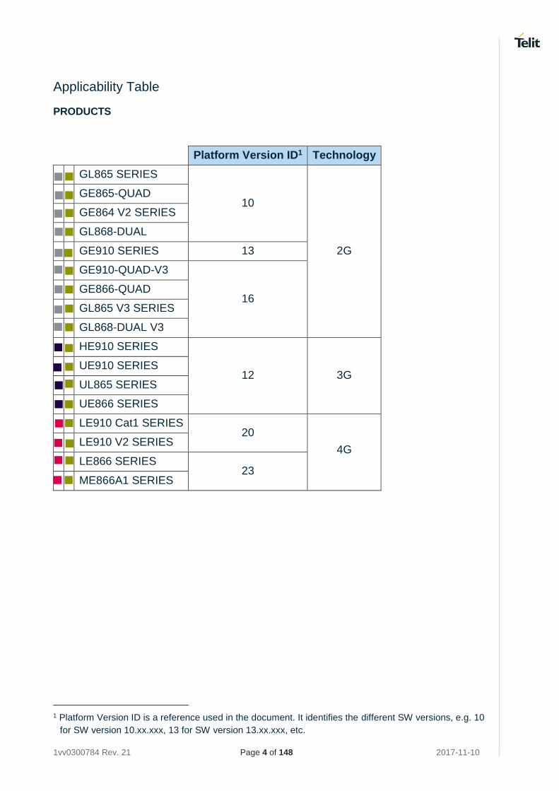
Applicability Table
PRODUCTS
Platform Version ID1 Technology
GL865 SERIES
10
2G
GE865-QUAD
GE864 V2 SERIES
GL868-DUAL
GE910 SERIES 13
GE910-QUAD-V3
16
GE866-QUAD
GL865 V3 SERIES
GL868-DUAL V3
HE910 SERIES
12 3G
UE910 SERIES UL865 SERIES
UE866 SERIES
LE910 Cat1 SERIES 20
4G
LE910 V2 SERIES
LE866 SERIES 23
ME866A1 SERIES
1 Platform Version ID is a reference used in the document. It identifies the different SW versions, e.g. 10
for SW version 10.xx.xxx, 13 for SW version 13.xx.xxx, etc.
1vv0300784 Rev. 21 Page 5 of 148 2017-11-10
Contents
NOTICES LIST ............................................................................................... 2
COPYRIGHTS ................................................................................................ 2
COMPUTER SOFTWARE COPYRIGHTS ...................................................... 2
USAGE AND DISCLOSURE RESTRICTIONS ............................................... 3
I. License Agreements ..................................................................... 3
II. Copyrighted Materials ................................................................... 3
III. High Risk Materials ....................................................................... 3
IV. Trademarks .................................................................................. 3
V. Third Party Rights ......................................................................... 3
APPLICABILITY TABLE ................................................................................ 4
CONTENTS .................................................................................................... 5
FIGURES LIST ............................................................................................. 12
TABLES LIST ............................................................................................... 12
AT COMMANDS LIST .................................................................................. 13
1 INTRODUCTION ........................................................................ 14
1.1 Scope ......................................................................................... 14
1.2 Audience..................................................................................... 14
1.3 Contact Information, Support ...................................................... 14
1.4 Text Conventions ........................................................................ 15
1.5 Related Documents .................................................................... 16
2 PRELIMINARY INFORMATION ................................................. 17
3 AT COMMANDS ........................................................................ 18
3.1 The Main Serial Port ................................................................... 18
3.1.1 RTS/CTS handshaking ............................................................... 18
3.1.1.1 RTS control line .......................................................................... 18
3.1.1.1.1 2G Modules ................................................................................ 18
3.1.1.1.2 3G Modules ................................................................................ 20
3.1.1.2 CTS control line .......................................................................... 20
3.2 Serial Port Speed ........................................................................ 21
3.2.1 2G Modules ................................................................................ 21
3.2.1.1 SW Ver. 10.xx.xxx, 16.xx.xxx ...................................................... 21
3.2.1.2 SW Ver. 13.xx.xxx ...................................................................... 21
1vv0300784 Rev. 21 Page 6 of 148 2017-11-10
3.2.2 3G Modules ................................................................................ 22
3.2.2.1 SW Ver. 12.xx.xxx ...................................................................... 22
3.2.3 4G Modules ................................................................................ 22
3.3 Serial Ports Arrangements .......................................................... 23
3.4 Auxiliary Serial Port Arrangement ............................................... 23
3.4.1 2G Modules ................................................................................ 23
3.5 AT Interface Style Selection ........................................................ 24
3.5.1 2G Modules ................................................................................ 24
3.5.2 3G/4G Modules........................................................................... 24
3.6 AT Error Report Format .............................................................. 25
3.7 Module Identification ................................................................... 25
3.8 Select the Network ...................................................................... 25
3.8.1 2G Modules ................................................................................ 25
3.8.2 3G Modules ................................................................................ 25
3.8.3 4G Modules ................................................................................ 26
3.9 Band Configuration ..................................................................... 27
3.9.1 2G Modules ................................................................................ 27
3.9.2 3G Modules ................................................................................ 27
3.9.3 4G Modules ................................................................................ 28
3.10 SIM/USIM Management .............................................................. 29
3.10.1 SIM Presence and PIN Request ................................................. 29
3.10.2 Enter PIN code ........................................................................... 29
3.10.3 Enter PUK code .......................................................................... 30
3.10.4 SIM Status .................................................................................. 30
3.10.5 SIM Detection Mode ................................................................... 31
3.10.6 SIM/USIM Access File ................................................................ 33
3.10.7 MSISDN ..................................................................................... 33
3.11 Network Information .................................................................... 35
3.11.1 Network Status ........................................................................... 35
3.11.1.1 2G Modules ................................................................................ 35
3.11.1.2 3G Modules ................................................................................ 35
3.11.1.3 4G Modules ................................................................................ 36
3.11.2 Network Operator Identification ................................................... 36
3.11.2.1 2G Modules ................................................................................ 37
3.11.2.2 3G Modules ................................................................................ 37
3.11.2.3 4G Modules ................................................................................ 38
3.11.3 Preferred Network Operator List ................................................. 39
1vv0300784 Rev. 21 Page 7 of 148 2017-11-10
3.11.3.1 2G Modules ................................................................................ 39
3.11.3.2 3G Modules ................................................................................ 40
3.11.3.3 4G Modules ................................................................................ 40
3.11.4 Signal Strength & Quality ............................................................ 41
3.11.5 Fast Network Status Check ........................................................ 41
3.11.5.1 2G Modules ................................................................................ 42
3.11.5.2 3G Modules ................................................................................ 43
3.11.5.3 4G Modules ................................................................................ 43
3.11.6 Network Survey .......................................................................... 44
3.11.7 BCCH Survey ............................................................................. 45
3.11.8 ENS, OMA-DM, and AT&T functions .......................................... 46
3.11.8.1 2G Modules SW Ver. ≥ 10.00.xx5/16.00.xx2 ............................... 46
3.11.8.1.1 No AT&T SIM Card ..................................................................... 46
3.11.8.1.2 AT&T SIM card ........................................................................... 47
3.11.8.2 2G Modules SW Ver. ≥ 13.00.xx2 ............................................... 48
3.11.8.2.1 No AT&T SIM cards .................................................................... 48
3.11.8.2.2 AT&T SIM card ........................................................................... 48
3.11.8.3 3G Modules SW Ver. = 12.00.xx2 ............................................... 49
3.11.8.3.1 No AT&T SIM cards .................................................................... 49
3.11.8.3.2 AT&T SIM card ........................................................................... 50
3.11.8.4 3G Modules SW Ver. ≥ 12.00.xx3 ............................................... 51
3.11.8.4.1 No AT&T SIM cards .................................................................... 51
3.11.8.4.2 AT&T SIM card ........................................................................... 51
3.11.8.5 AT&T OMA-DM client ................................................................. 53
3.11.8.5.1 #ENAOMADM automatic enabling and disabling ........................ 53
3.11.8.5.2 AT&T Host Odis Timeout for Alerting the Server ......................... 53
3.11.8.5.3 Multiple AT&T Host Odis Alerting Rules ...................................... 54
3.11.8.5.4 AT&T Host Odis OMA-DM Session active .................................. 54
3.11.8.5.5 AT&T Multiple Host Odis Setting and Memory Management ...... 55
3.11.8.5.6 #HOSTODIS Alerting Server trigger ............................................ 55
3.11.8.5.7 AT&T SIMs with one APN ........................................................... 55
3.12 Voice Call Establishment – Originate .......................................... 56
3.12.1 Set Module in Voice Mode .......................................................... 56
3.12.2 Dialing a Phone Number ............................................................. 56
3.12.3 Disconnect a Call ........................................................................ 56
3.12.4 Answering an Incoming Call........................................................ 57
3.12.5 Audio Codec Information ............................................................ 57
1vv0300784 Rev. 21 Page 8 of 148 2017-11-10
3.12.6 Setting Audio Codec ................................................................... 57
3.12.7 Set Audio Path Active ................................................................. 58
3.12.8 Set Volume on Speaker .............................................................. 59
3.12.9 Set Microphone Mute .................................................................. 59
3.12.10 Hand Set Path Commands ......................................................... 59
3.12.10.1 HS Microphone Gain .................................................................. 59
3.12.10.2 HS Sidetone ............................................................................... 60
3.12.10.3 HS Echo Canceller ..................................................................... 60
3.12.10.4 HS Automatic Gain ..................................................................... 60
3.12.10.5 HS Noise Reduction ................................................................... 61
3.12.11 Hands Free Path Commands ...................................................... 61
3.12.11.1 HF Microphone Gain ................................................................... 61
3.12.11.2 HF Sidetone ................................................................................ 62
3.12.11.3 HF Echo Canceller ...................................................................... 62
3.12.11.4 HF Automatic Gain ..................................................................... 63
3.12.11.5 HF Noise Reduction .................................................................... 63
3.13 CSD Data Call Establishing – Originate ...................................... 64
3.13.1 Set Module in ONLINE Mode ...................................................... 64
3.13.2 Dialing a Phone Number ............................................................. 64
3.13.3 Disconnect Data Call .................................................................. 64
3.13.4 Set Modulation and Speed .......................................................... 65
3.13.4.1 2G Modules ................................................................................ 65
3.13.4.2 3G Modules ................................................................................ 65
3.13.5 Modules Supporting Only Data Call ............................................ 65
3.14 GSM Single Numbering Scheme ................................................ 67
3.14.1 2G Modules ................................................................................ 67
3.15 TTY Feature ............................................................................... 67
3.16 Software Shutdown ..................................................................... 67
3.17 Call Management ........................................................................ 68
3.17.1 Identifying the Call Type ............................................................. 68
3.17.2 Identify the Caller ........................................................................ 68
3.17.3 Calling Line Indication ................................................................. 69
3.17.3.1 CLIR Service Status ................................................................... 69
3.17.3.2 Restrict/Allow Caller Line ID Indication ....................................... 70
3.17.4 Call Barring Control .................................................................... 70
3.17.4.1 Lock/Unlock the Module .............................................................. 70
3.17.4.1.1 2G Modules ................................................................................ 71
1vv0300784 Rev. 21 Page 9 of 148 2017-11-10
3.17.4.1.2 3G Modules ................................................................................ 71
3.17.4.2 Call Barring Service Status ......................................................... 71
3.17.4.3 Bar/Unbar All Incoming Calls ...................................................... 72
3.17.4.4 Bar/Unbar Incoming Calls in International Roaming .................... 73
3.17.4.5 Bar/Unbar All Outgoing Calls ...................................................... 74
3.17.4.6 Bar/Unbar All Outgoing International Calls .................................. 75
3.17.4.7 Bar/Unbar All Outgoing Internat. Calls except to Home Country . 76
3.17.4.8 Unbar All Calls ............................................................................ 77
3.18 DTMF Tones ............................................................................... 78
3.19 Encryption Algorithm ................................................................... 78
3.20 SMS Management ...................................................................... 79
3.20.1 Select SMS Format Type ............................................................ 79
3.20.1.1 Set Text Mode Parameters ......................................................... 79
3.20.1.2 Character Sets ............................................................................ 80
3.20.1.2.1 IRA Character Set ....................................................................... 81
3.20.1.2.2 UCS2 Character Set ................................................................... 82
3.20.2 Read SMSC Number .................................................................. 82
3.20.3 Set SMSC Number ..................................................................... 82
3.20.4 Send a SMS ............................................................................... 83
3.20.4.1 2G Modules ................................................................................ 83
3.20.4.2 3G Modules ................................................................................ 85
3.20.5 Select/Check SMS Storage Type ................................................ 85
3.20.5.1 2G Modules ................................................................................ 85
3.20.5.2 3G Modules ................................................................................ 86
3.20.6 Select URC Behavior .................................................................. 86
3.20.6.1 2G Modules ................................................................................ 86
3.20.6.2 3G Modules ................................................................................ 87
3.20.7 Store a SMS ............................................................................... 87
3.20.7.1 2G Modules ................................................................................ 87
3.20.7.2 3G Modules ................................................................................ 89
3.20.7.3 PDU Mode .................................................................................. 90
3.20.8 Send a Stored SMS .................................................................... 90
3.20.9 Send a New SMS using GPRS service ....................................... 91
3.20.10 Delete an SMS ........................................................................... 92
3.20.10.1 2G Modules ................................................................................ 92
3.20.11 Read an SMS ............................................................................. 93
3.20.12 SMS Status ................................................................................. 93
1vv0300784 Rev. 21 Page 10 of 148 2017-11-10
3.20.12.1 2G Modules ................................................................................ 94
3.20.13 Cell Broadcast Service ................................................................ 94
3.20.14 Read concatenated SMS ............................................................ 95
3.21 Phonebooks ................................................................................ 98
3.21.1 Phonebook Storage .................................................................... 98
3.21.1.1 2G Modules ................................................................................ 98
3.21.1.2 3G/4G Modules........................................................................... 99
3.21.2 Search Phonebook Entries ....................................................... 100
3.21.3 Read Phonebook Entries .......................................................... 100
3.21.4 Write Phonebook Entry ............................................................. 101
3.21.5 Delete Phonebook Entry ........................................................... 101
3.21.6 Dial Phonebook Entry ............................................................... 101
3.22 GSM Power Saving Modes ....................................................... 103
3.22.1 CFUN=0 and 3G Modules ......................................................... 104
3.22.2 CFUNs and the Main Serial Port ............................................... 104
3.22.3 CFUNs and Wake up Events .................................................... 107
3.22.4 CFUN Examples ....................................................................... 110
3.22.4.1 CFUN=0: Call, SMS, #QSS, +CALA ......................................... 110
3.22.4.2 CFUN=2: #QSS, +CALA ........................................................... 113
3.22.4.3 CFUN=4: #QSS, +CALA ........................................................... 114
3.22.4.4 CFUN=5: Call, SMS, +CALA ..................................................... 116
3.22.4.5 CFUN=7: Call, SMS, +CALA ..................................................... 120
3.22.4.6 CFUN=10: +CALA .................................................................... 124
3.22.4.7 CFUN=11: +CALA .................................................................... 125
3.23 GPIO Pins ................................................................................. 127
3.23.1 Set GPIO Pin as OUTPUT ........................................................ 127
3.23.2 Set GPIO Pin as INPUT ............................................................ 127
3.23.3 GPIO Pin Status ....................................................................... 127
3.23.4 GPIO & Alternate Function ....................................................... 128
3.23.4.1 GPIO4 Pin as RF Transmission Control .................................... 128
3.23.4.2 GPIO5 Pin as RFTXMON OUTPUT .......................................... 129
3.23.4.3 GPIO6 Pin as ALARM OUTPUT ............................................... 129
3.23.4.4 GPIO7 Pin as BUZZER OUTPUT ............................................. 129
3.23.4.5 Set STAT_LED GPIO ............................................................... 130
3.23.4.6 JAM GPIO ................................................................................ 130
3.23.4.6.1 2G Modules .............................................................................. 130
3.23.4.6.2 3G Modules .............................................................................. 130
1vv0300784 Rev. 21 Page 11 of 148 2017-11-10
3.24 Clock and Alarm Functions ....................................................... 131
3.24.1 Clock ........................................................................................ 131
3.24.1.1 Set Module Clock ...................................................................... 131
3.24.1.2 Read the Current Date and Time .............................................. 131
3.24.1.3 Automatic Data/Time updating .................................................. 132
3.24.2 Alarm ........................................................................................ 133
3.24.2.1 Set Alarm .................................................................................. 133
3.24.2.2 Delete Alarm ............................................................................. 133
3.24.2.3 Recurrent Alarm ........................................................................ 135
3.24.2.4 Postpone Alarm Time ............................................................... 136
3.24.2.5 Stop Alarm ................................................................................ 136
3.24.2.6 Alarm Status ............................................................................. 137
3.24.2.7 A simple Alarm Application ....................................................... 137
4 APPENDIX ............................................................................... 139
4.1 Firmware Update Tool .............................................................. 139
4.1.1 Xfp tool ..................................................................................... 139
4.1.1.1 Command Line running Xfp tool ................................................ 141
5 GLOSSARY AND ACRONYMS ............................................... 143
6 DOCUMENT HISTORY ............................................................ 145
1vv0300784 Rev. 21 Page 12 of 148 2017-11-10
Figures List
Fig. 1: RTS/CTS control lines .................................................................................................... 18
Fig. 2: RTS Control Line ............................................................................................................ 19
Fig. 3: CTS Control Line ............................................................................................................ 20
Fig. 4: CFUN=7, Cyclic Sleep ................................................................................................. 105
Tables List
Tab. 1: Serial Port Speed & Autobauding .................................................................................. 21
Tab. 2: AT#SII & AT Parsers ..................................................................................................... 23
Tab. 3: SIM/USIM ..................................................................................................................... 33
Tab. 4: Modules Supporting OMA-DM ...................................................................................... 53
Tab. 5: Audio Paths .................................................................................................................. 58
Tab. 6: CFUN Modes & Software Versions ............................................................................. 103
Tab. 7: CFUN Modes & Wake up Events (con't) ..................................................................... 108
1vv0300784 Rev. 21 Page 13 of 148 2017-11-10
AT Commands List
The following list, organized in alphabetical order, shows the AT commands covered by this User Guide. The number close to each command indicates the page of the first AT command occurrence.
AT ...................................... 18 AT# RFSTS ....................... 43 AT#AUTOBND .................. 27 AT#BND ............................ 27 AT#CAP............................. 58 AT#CCLK ........................ 132 AT#CMGLCONCINDEX .... 96 AT#CODEC ....................... 57 AT#CODECINFO .............. 57 AT#CSURV ....................... 44 AT#ENAOMADM .............. 53 AT#ENCALG ..................... 78 AT#GPIO ......................... 127 AT#HFMICG ...................... 61 AT#HOSTODIS ................. 53 AT#HSMICG ...................... 59 AT#JDRENH ................... 130 AT#MONI ........................... 41 AT#NITZ .......................... 132 AT#PORTCFG .................. 23 AT#QSS............................. 30 AT#SERVINFO .................. 41 AT#SHDN .......................... 67 AT#SHFAGC ..................... 63 AT#SHFEC ........................ 62 AT#SHFNR ........................ 63 AT#SHFSD ........................ 62 AT#SHSAGC ..................... 60 AT#SHSEC ........................ 60 AT#SHSNR ....................... 61
AT#SHSSD ....................... 60 AT#SII................................ 23 AT#SIMDET ...................... 31 AT#SLED ........................ 130 AT#SLEDSAV ................. 130 AT#SMSMODE ................. 83 AT#WAKE ....................... 137 AT#WAKE ....................... 135 AT&P0 ............................... 21 AT&W0 .............................. 21 AT+CALA ........................ 133 AT+CALD ........................ 134 AT+CAPD ........................ 136 AT+CBST .......................... 65 AT+CCLK ........................ 131 AT+CFUN ........................ 103 AT+CGATT ....................... 91 AT+CGMM ........................ 25 AT+CGMR ......................... 25 AT+CLCK .......................... 70 AT+CLIP ............................ 68 AT+CLIR ........................... 69 AT+CLVL .......................... 59 AT+CMEE ......................... 25 AT+CMGD ......................... 92 AT+CMGF ......................... 79 AT+CMGL ......................... 93 AT+CMGW ........................ 87 AT+CMSS ......................... 89 AT+CMUT ......................... 59
AT+CNMI .......................... 86 AT+CNUM ......................... 34 AT+COPS ......................... 36 AT+CPBF ........................ 100 AT+CPBR ....................... 100 AT+CPBS .......................... 98 AT+CPBW ....................... 101 AT+CPIN ........................... 29 AT+CPMS ......................... 85 AT+CPOL .......................... 39 AT+CRC ............................ 68 AT+CREG ......................... 35 AT+CRSM ......................... 33 AT+CSCA ......................... 82 AT+CSCB ......................... 95 AT+CSCS .......................... 80 AT+CSIM ........................... 33 AT+CSMP ......................... 79 AT+CSNS .......................... 67 AT+CSQ ............................ 41 AT+FCLASS ..................... 56 AT+IPR .............................. 21 AT+SELINT ....................... 24 AT+SNUM ......................... 34 AT+WS46 .......................... 25 ATA ................................... 57 ATD ................................... 56 ATH ................................... 56
1vv0300784 Rev. 21 Page 14 of 148 2017-11-10
1 INTRODUCTION
1.1 Scope
This document covers the more significant standard and proprietary AT commands provided by Telit's modules. Several module features are described and for each one of them the related AT commands are explained through examples. This document is not an exhaustive description of the AT commands implemented on the Telit's modules series, its target is only to give you an entry point to the AT commands world.
1.2 Audience
The present User Guide is addressed to users that need to learn and use quickly standard and
proprietary AT commands. The reader can learn the use of the AT commands through simple
examples shown in the document, and then deepen the interested AT commands reading the
documents [1]/[17]/[26]/[27] in accordance with the used module.
1.3 Contact Information, Support
For general contact, technical support services, technical questions and report documentation errors contact Telit Technical Support at:
• [email protected] (for Short Range Devices)
Alternatively, use:
http://www.telit.com/support
For detailed information about where you can buy the Telit modules or for recommendations on
accessories and components visit:
http://www.telit.com
Our aim is to make this guide as helpful as possible. Keep us informed of your comments and
suggestions for improvements.
Telit appreciates feedback from the users of our information.
1vv0300784 Rev. 21 Page 15 of 148 2017-11-10
1.4 Text Conventions
Danger – This information MUST be followed or catastrophic equipment failure or
bodily injury may occur.
Caution or Warning – Alerts the user to important points about integrating the
module, if these points are not followed, the module and end user equipment may
fail or malfunction.
Tip or Information – Provides advice and suggestions that may be useful when
integrating the module.
All dates are in ISO 8601 format, i.e. YYYY-MM-DD.
1vv0300784 Rev. 21 Page 16 of 148 2017-11-10
1.5 Related Documents
[1] AT Commands Reference Guide, 80000ST10025a [2] Refer to the specific "Telit Product Description" document [3] Refer to the specific "Telit Hardware User Guide" document [4] IP Easy User Guide, 80000ST10028A [5] ETSI GSM 07.07, 27.07 [6] EVK2 User Guide, 1vv0300704 [7] ETSI GSM 03.38, 23.038 [8] SSL/TLS User Guide, 1vv0300989 [9] Device Requirements AT&T, Document Number 13340 [10] Telit 3G Modules Ports Arrangements User Guide, 1vv0300971 [11] Enhanced JDR Technical Note, 30353NT11086A [12] ITU-T Recommendation E.164 [13] ETSI GSM 11.11, 51.011, 31.101, 31.102 [14] ITU-T Recommendation V.24 [15] Telit USB Drivers Installer User Guide, 1vv0301164 [16] ETSI GSM 11.14, 51.014 [17] Telit 3G Modules AT Commands Reference Guide, 80378ST10091A [18] Audio Setting Application Note, 80000NT10007A [19] ETSI GSM 27.005 [20] Telit’s Easy Scan User Guide, 1vv0300972 [21] Jamming Detection – HE910 Series Application Note, 80000NT11408A [22] GE910 Series Ports Arrangements User Guide, 1vv0301049 [23] LE910 V2, LE910 Cat1 Ports Arrangements User Guide, 1vv0301252 [24] Virtual Serial Device Application Note, 80000NT10045A [25] LE910 V2, LE910 Cat1 NCM Protocol User Guide, 1vv0301246 [26] Telit LE910 V2 Series AT Commands Reference Guide, 80446ST10707A [27] LE866 Series AT Commands Reference Guide, 80471ST10691A [28] LE866, ME866A1 Ports Arrangements User Guide, 1vv0301469
1vv0300784 Rev. 21 Page 17 of 148 2017-11-10
2 PRELIMINARY INFORMATION
Before describing the AT commands use, it is needed to define a way to point out significant differences, when needed, between modules belonging to different series, or having different software versions.
• In 2G Modules sub-chapters (or under label in the text) are described AT commands examples concerning the modules supporting the 2G Technology only. Where needed, the guide specifies also the software version.
• In 3G Modules sub-chapters (or under label in the text) are described AT commands examples concerning the modules supporting the 2G/3G Technologies. Where needed, the guide specifies also the software version.
• In 4G Modules sub-chapters (or under label in the text) are described AT commands examples concerning the modules supporting the 4G Technologies. Where needed, the guide specifies also the software version.
• If the AT command example is valid for all products, no labels or dedicated chapters are used.
• To have information on AT commands managing the connectivity of the modules (2G, 3G, and 4G) refer to documents [4], and [8].
The AT commands use, specified in this guide, assumes that the #SELINT =2 AT Interface Style is used. Refer to document [1]/[17]/[26]/[28] in accordance with the module that you are using to have more information on the AT commands syntax, parameters, and parameters range. Refer to document [3], in accordance with the module that you are using, to have information on the hardware. For example, serial ports, GPIO pins, etc. Refer to document [18] to have detailed information on the audio architecture provided by the modules.
1vv0300784 Rev. 21 Page 18 of 148 2017-11-10
3 AT COMMANDS
3.1 The Main Serial Port
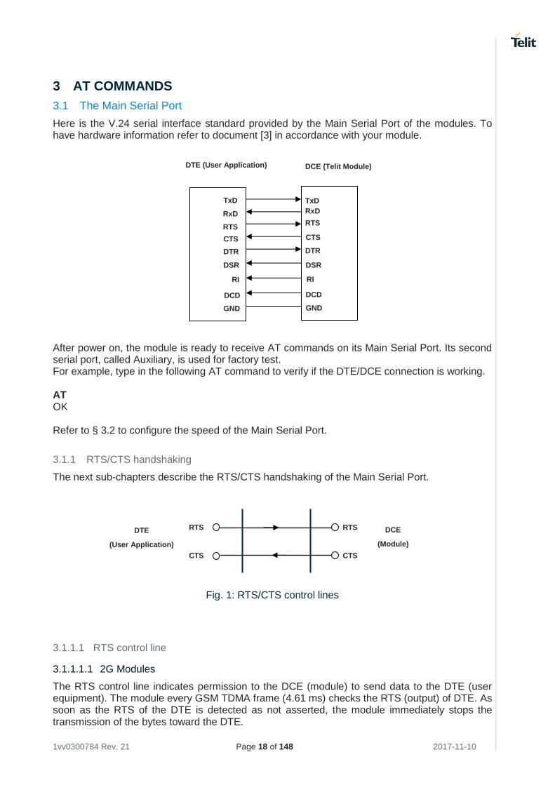
Here is the V.24 serial interface standard provided by the Main Serial Port of the modules. To have hardware information refer to document [3] in accordance with your module. After power on, the module is ready to receive AT commands on its Main Serial Port. Its second serial port, called Auxiliary, is used for factory test. For example, type in the following AT command to verify if the DTE/DCE connection is working. AT OK Refer to § 3.2 to configure the speed of the Main Serial Port.
3.1.1 RTS/CTS handshaking
The next sub-chapters describe the RTS/CTS handshaking of the Main Serial Port.
Fig. 1: RTS/CTS control lines
3.1.1.1 RTS control line
3.1.1.1.1 2G Modules
The RTS control line indicates permission to the DCE (module) to send data to the DTE (user equipment). The module every GSM TDMA frame (4.61 ms) checks the RTS (output) of DTE. As soon as the RTS of the DTE is detected as not asserted, the module immediately stops the transmission of the bytes toward the DTE.
DTE (User Application) DCE (Telit Module)
TxD
RxD
RTS
CTS
DTR
DSR
RI
DCD
GND
TxD
RxD
RTS
CTS
DTR
DSR
RI
DCD
GND
DCE
(Module)
DTE
(User Application)
RTS
CTS
RTS
CTS
1vv0300784 Rev. 21 Page 19 of 148 2017-11-10
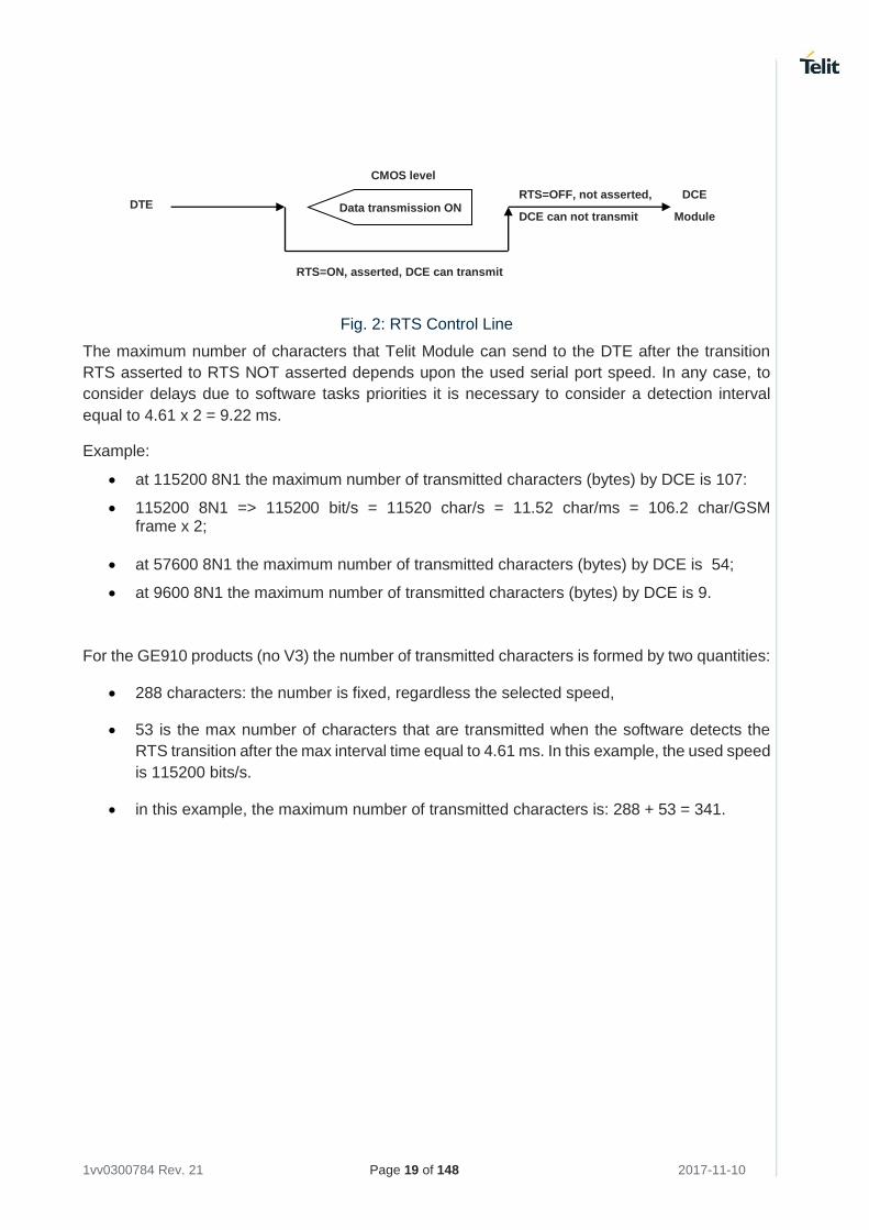
Fig. 2: RTS Control Line
The maximum number of characters that Telit Module can send to the DTE after the transition
RTS asserted to RTS NOT asserted depends upon the used serial port speed. In any case, to
consider delays due to software tasks priorities it is necessary to consider a detection interval
equal to 4.61 x 2 = 9.22 ms.
Example:
• at 115200 8N1 the maximum number of transmitted characters (bytes) by DCE is 107:
• 115200 8N1 => 115200 bit/s = 11520 char/s = 11.52 char/ms = 106.2 char/GSM frame x 2;
• at 57600 8N1 the maximum number of transmitted characters (bytes) by DCE is 54;
• at 9600 8N1 the maximum number of transmitted characters (bytes) by DCE is 9.
For the GE910 products (no V3) the number of transmitted characters is formed by two quantities:
• 288 characters: the number is fixed, regardless the selected speed,
• 53 is the max number of characters that are transmitted when the software detects the
RTS transition after the max interval time equal to 4.61 ms. In this example, the used speed
is 115200 bits/s.
• in this example, the maximum number of transmitted characters is: 288 + 53 = 341.
RTS=OFF, not asserted,
DCE can not transmit DTE
DCE
Module
RTS=ON, asserted, DCE can transmit
CMOS level
Data transmission ON
1vv0300784 Rev. 21 Page 20 of 148 2017-11-10
3.1.1.1.2 3G Modules
HE910 Series
RTS control line indicates permission to the DCE (module) to send data to the DTE (user equipment). The low-high RTS transition generates an interrupt signal. Between the RTS transition and the interrupt signal recognition, the module can send at most one character toward DTE.
Suppose that the HE910 module is in ONLINE Mode and the DTE forces the RTS control line to
high, see Fig. 2 . The data flow from the module to the DTE (download) is stopped. At the same
time, the CTS control line is low - see Fig. 3 -, it means that the module can receive data from
DTE (upload). Follow the steps below to force the module in the COMMAND Mode:
• Enter the escape sequence: +++
• Force the RTS to low. The Tx buffer of the module will be emptied, and the OK message
will be displayed.
• Now, the module is in COMMAND Mode.
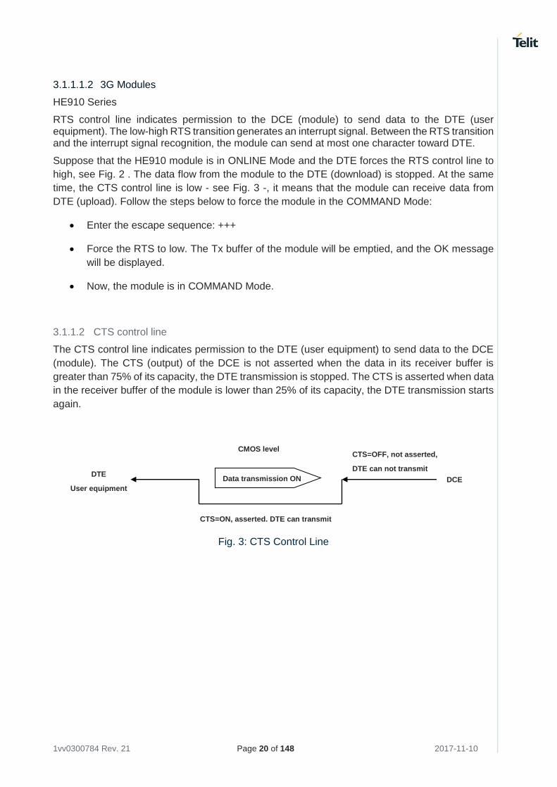
3.1.1.2 CTS control line
The CTS control line indicates permission to the DTE (user equipment) to send data to the DCE
(module). The CTS (output) of the DCE is not asserted when the data in its receiver buffer is
greater than 75% of its capacity, the DTE transmission is stopped. The CTS is asserted when data
in the receiver buffer of the module is lower than 25% of its capacity, the DTE transmission starts
again.
Fig. 3: CTS Control Line
CTS=OFF, not asserted,
DTE can not transmit DTE
User equipment DCE
CTS=ON, asserted. DTE can transmit
CMOS level
Data transmission ON
1vv0300784 Rev. 21 Page 21 of 148 2017-11-10
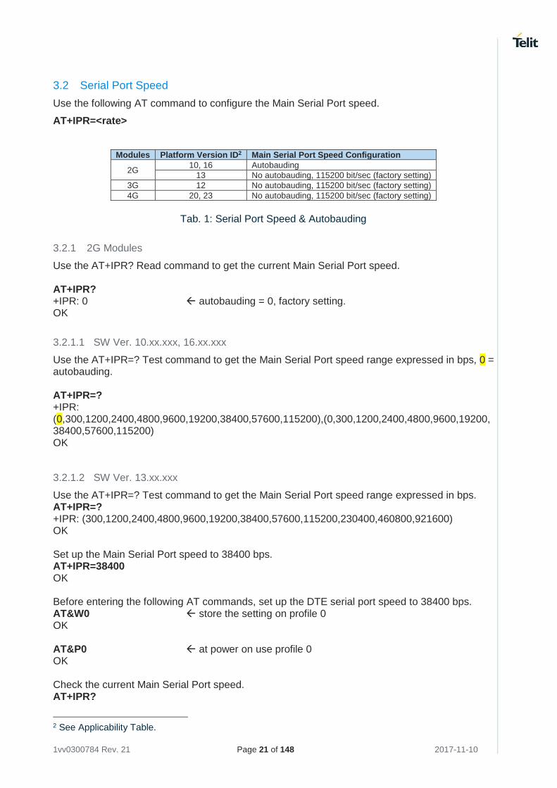
3.2 Serial Port Speed
Use the following AT command to configure the Main Serial Port speed.
AT+IPR=<rate>
Modules Platform Version ID2 Main Serial Port Speed Configuration
2G 10, 16 Autobauding
13 No autobauding, 115200 bit/sec (factory setting)
3G 12 No autobauding, 115200 bit/sec (factory setting)
4G 20, 23 No autobauding, 115200 bit/sec (factory setting)
Tab. 1: Serial Port Speed & Autobauding
3.2.1 2G Modules
Use the AT+IPR? Read command to get the current Main Serial Port speed. AT+IPR? +IPR: 0 autobauding = 0, factory setting. OK
3.2.1.1 SW Ver. 10.xx.xxx, 16.xx.xxx
Use the AT+IPR=? Test command to get the Main Serial Port speed range expressed in bps, 0 = autobauding. AT+IPR=? +IPR: (0,300,1200,2400,4800,9600,19200,38400,57600,115200),(0,300,1200,2400,4800,9600,19200,38400,57600,115200) OK
3.2.1.2 SW Ver. 13.xx.xxx
Use the AT+IPR=? Test command to get the Main Serial Port speed range expressed in bps. AT+IPR=? +IPR: (300,1200,2400,4800,9600,19200,38400,57600,115200,230400,460800,921600) OK Set up the Main Serial Port speed to 38400 bps. AT+IPR=38400 OK Before entering the following AT commands, set up the DTE serial port speed to 38400 bps. AT&W0 store the setting on profile 0 OK AT&P0 at power on use profile 0 OK Check the current Main Serial Port speed. AT+IPR?
2 See Applicability Table.
1vv0300784 Rev. 21 Page 22 of 148 2017-11-10
+IPR: 38400 OK
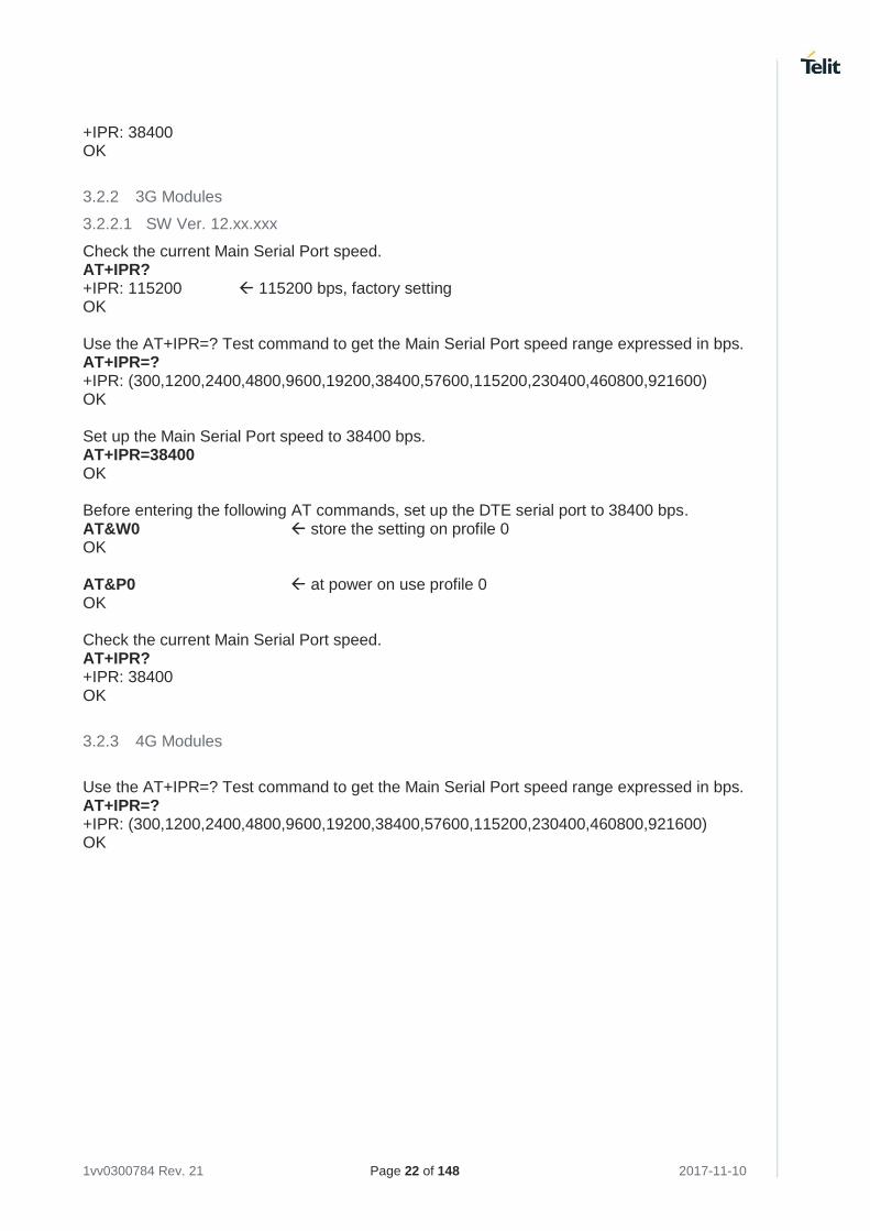
3.2.2 3G Modules
3.2.2.1 SW Ver. 12.xx.xxx
Check the current Main Serial Port speed. AT+IPR? +IPR: 115200 115200 bps, factory setting OK Use the AT+IPR=? Test command to get the Main Serial Port speed range expressed in bps. AT+IPR=? +IPR: (300,1200,2400,4800,9600,19200,38400,57600,115200,230400,460800,921600) OK Set up the Main Serial Port speed to 38400 bps. AT+IPR=38400 OK Before entering the following AT commands, set up the DTE serial port to 38400 bps. AT&W0 store the setting on profile 0 OK AT&P0 at power on use profile 0 OK Check the current Main Serial Port speed. AT+IPR? +IPR: 38400 OK
3.2.3 4G Modules
Use the AT+IPR=? Test command to get the Main Serial Port speed range expressed in bps. AT+IPR=? +IPR: (300,1200,2400,4800,9600,19200,38400,57600,115200,230400,460800,921600) OK
1vv0300784 Rev. 21 Page 23 of 148 2017-11-10
3.3 Serial Ports Arrangements
The #PORTCFG command manages the serial ports arrangements of the modules. To have
exhaustive information on the command, refer to documents [10], [22], [23], and [28] according to
the used module.
3.4 Auxiliary Serial Port Arrangement
3.4.1 2G Modules
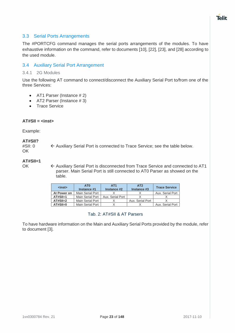
Use the following AT command to connect/disconnect the Auxiliary Serial Port to/from one of the three Services:
• AT1 Parser (Instance # 2)
• AT2 Parser (Instance # 3)
• Trace Service AT#SII = <inst> Example: AT#SII? #SII: 0 Auxiliary Serial Port is connected to Trace Service; see the table below. OK AT#SII=1 OK Auxiliary Serial Port is disconnected from Trace Service and connected to AT1
parser. Main Serial Port is still connected to AT0 Parser as showed on the table.
<inst> AT0
Instance #1 AT1
Instance #2 AT2
Instance #3 Trace Service
At Power on Main Serial Port X X Aux. Serial Port
AT#SII=1 Main Serial Port Aux. Serial Port X X
AT#SII=2 Main Serial Port X Aux. Serial Port X
AT#SII=0 Main Serial Port X X Aux. Serial Port
Tab. 2: AT#SII & AT Parsers
To have hardware information on the Main and Auxiliary Serial Ports provided by the module, refer to document [3].
1vv0300784 Rev. 21 Page 24 of 148 2017-11-10
3.5 AT Interface Style Selection
Use the following AT command to check the current AT Interface Style.
AT#SELINT?
3.5.1 2G Modules
After powering ON the module, check the current AT command Interface Style. AT#SELINT? #SELINT: 0 OK Check the AT command Interfaces Set supported. AT#SELINT=? #SELINT: (0-2) OK Select the desired AT command Interface Set. AT#SELINT=2 OK Select a wrong AT command Interface Set just to see the response. AT#SELINT=7 ERROR Check that AT command Interface is active. AT#SELINT? #SELINT: 2 OK
3.5.2 3G/4G Modules
Check the supported AT Command Interface Style. AT#SELINT=? #SELINT: (2) only interface style 2 is supported. OK
1vv0300784 Rev. 21 Page 25 of 148 2017-11-10
3.6 AT Error Report Format
Disable the error report in numerical and verbose format. AT+CMEE=0 OK Enable the error report in numerical format. AT+CMEE=1 OK Enable the error report in verbose format. AT+CMEE=2 OK
3.7 Module Identification
Use the following AT commands to verify the Software Versions and module identification. Check the Software Versions. AT+CGMR 10.00.004 OK Check the module identification. AT+CGMM GM862-QUAD OK
3.8 Select the Network
The following AT command selects the technology (2G/3G/4G). The command syntax is: AT+WS46=[<n>] Use the Test command to know the <n> parameter range of the used module. AT+WS46=?
The <n> parameter is stored in NVM, and the command will take effect on the next power on.
3.8.1 2G Modules
Select 2G technology, the only available. AT+WS46=12 OK
3.8.2 3G Modules
Select 2G technology. AT+WS46=12 OK
1vv0300784 Rev. 21 Page 26 of 148 2017-11-10
Select 3G technology only. AT+WS46=22 OK Select both technologies: 2G and 3G. If on the air are present both technologies 2G and 3G, the second one is preferred AT+WS46=25 OK
3.8.3 4G Modules
Example: 4G/2G only products Model identification AT+CGMM LE910-EU1 OK Check the <n> range AT+WS46=? +WS46: (12,28,30) OK Where:
12 GSM Digital Cellular Systems (GERAN only)
28 E-UTRAN only
30 GERAN and E-UTRAN (default)
Example: 4G only product. Model identification AT+CGMM LE866A1-NA OK Check the <n> range AT+WS46=? +WS46: (28) OK Where:
28 E-UTRAN only
1vv0300784 Rev. 21 Page 27 of 148 2017-11-10
3.9 Band Configuration
The following AT command enables/disables the automatic band selection at power-on. The command syntax is: AT#AUTOBND=[<value>] Use the Test command to know the <value> parameter range of the used module. AT#AUTOBND=?
3.9.1 2G Modules
Use the Test command to know the <value> parameter range. AT#AUTOBND=? #AUTOBND: (0-2) OK Enable the automatic band selection. AT#AUTOBND=2 OK Disable the automatic band selection (manual band selection): AT#AUTOBND=0 OK In manual band selection the following AT command selects the current band: AT#BND=[<band>] Example AT#BND=0 selected band: GSM 900MHz + DCS 1800MHz OK
3.9.2 3G Modules
Enable the automatic band selection: AT#AUTOBND=2 OK Disable the automatic band selection (manual band selection): AT#AUTOBND=0 OK In manual band selection the following AT command selects the current band for both technologies GERAN and UTRAN: AT#BND=[<band>][,<UMTS band>] Example AT#BND=0,0 selected band: GSM 900MHz + DCS 1800MHz 2100 MHz (FDD I) OK
1vv0300784 Rev. 21 Page 28 of 148 2017-11-10
The module uses a band out of the two selected with the #BND command. The selected band will be in accordance with the +WS46 command and the technologies available on the air.
Check the bands supported by the module AT#BND=? #BND: (0-3),(0-6) OK
3.9.3 4G Modules
Enables the automatic band selection (2 is the default): AT#AUTOBND=2 OK Disables the automatic band selection (manual band selection): AT#AUTOBND=0 OK In manual band selection, the AT command shown below, selects the current band from the following technologies: GERAN, UTRAN, and LTE. AT#BND=[<band>][,<UMTS band>[,<LTE band>]] Example 1 Model identification AT+CGMM LE866-SV1 OK Check the band ranges AT#BND=? #BND: (0),(0),(8-4104) OK Example 2 Model identification AT+CGMM LE910-EU1 OK Check the band ranges AT#BND=? #BND: (0),(0),(1-524485) OK
1vv0300784 Rev. 21 Page 29 of 148 2017-11-10
3.10 SIM/USIM Management
3.10.1 SIM Presence and PIN Request
The following AT command checks if the SIM device needs the PIN code. The command syntax is: AT+CPIN? Examples Assume that the SIM is inserted into the module and the PIN code is needed. AT+CPIN? +CPIN: SIM PIN OK Assume that the SIM is not inserted, and #CMEE=0. Check if PIN code is needed, just to see the command response: AT+CPIN? ERROR Assume that the SIM is not inserted, and #CMEE=1. Check if PIN code is needed, just to see the command response: AT+CPIN? +CME ERROR: 10 Assume that the SIM is not inserted, and #CMEE=2. Check if PIN code is needed, just to see the command response: AT+CPIN? +CME ERROR: SIM not inserted
3.10.2 Enter PIN code
Use the following AT command to enter the PIN code. The command syntax is: AT+CPIN=<pin> Examples Assume to enter a wrong PIN code, and Extended Error result is not enabled. AT+CPIN=1235 ERROR Now, enter the right PIN code: AT+CPIN=1234 OK Enable the error report in verbose format. AT+CMEE=2 OK Enter a wrong PIN code: AT+CPIN=1235 +CME ERROR: incorrect password.
1vv0300784 Rev. 21 Page 30 of 148 2017-11-10
After 3 attempts failed, the PIN code is no longer requested and the SIM is locked. Use SIM PUK to enter a new PIN code and unlock the SIM.
3.10.3 Enter PUK code
Enter the following AT command if PUK or PUK2 code is required. The command syntax is: AT+CPIN=<pin>[,<newpin>]
After 10 attempts failed, the SIM Card is locked and no longer available.
3.10.4 SIM Status
Use the following AT command to enable/disable the SIM Status Unsolicited Indication. The command syntax is: AT#QSS = <mode> Example 1 Enable the unsolicited indication concerning the SIM status change. AT#QSS=1 enable URCs: #QSS:0/1, see below. OK #QSS: 0 unsolicited indication: the SIM is extracted. #QSS: 1 unsolicited indication: the SIM is inserted. Example 2 AT#QSS=2 enable URCs: #QSS:0/1/2/3 OK AT+IPR=19200 select the Main Serial Port speed = DTE speed OK AT&W0 store the setting on profile 0 OK AT&P0 at Power on use profile 0 OK Now, power off the module: #QSS:1 unsolicited indication: SIM inserted Now, power on the module: #QSS:1 unsolicited indication: SIM inserted
1vv0300784 Rev. 21 Page 31 of 148 2017-11-10
AT+CPIN? +CPIN: SIM PIN SIM is locked OK AT+CPIN=<PIN> enter PIN OK #QSS: 2 unsolicited indication: SIM is unlocked #QSS: 3 unsolicited indication: SMS and Phonebook are accessible
The time interval between the two unsolicited indications (#QSS: 2 and #QSS: 3) depends from the number of SMS stored on the module and the Phonebook size.
3.10.5 SIM Detection Mode
Use the following AT command to manage the SIM detection mode. The command syntax is: AT#SIMDET=<mode> Examples Check the SIM detection mode. AT#SIMDET? #SIMDET: 2,1 OK Where:
2 = automatic SIM detection through SIMIN pin (Factory Setting) 1 = SIM inserted
Enable the unsolicited indication concerning the SIM status change. AT#QSS=1 OK Now, extract the SIM #QSS: 0 unsolicited indication: SIM is extracted Now, insert the SIM #QSS: 1 unsolicited indication: SIM is inserted AT#SIMDET=0 simulate SIM not inserted, but it is still physically inserted OK #QSS: 0 unsolicited indication, but SIM is NOT physically extracted AT#SIMDET? #SIMDET: 0,1 OK
1vv0300784 Rev. 21 Page 32 of 148 2017-11-10
Where:
0 = simulate the SIM status not inserted 1 = SIM is physically inserted
Now, extract/insert the SIM, no unsolicited indication appears on DTE! Extract the SIM again. AT#SIMDET=1 simulate SIM inserted, but it is still physically extracted OK AT#SIMDET? #SIMDET: 1,0 1 OK Where:
1 = simulate the SIM status inserted 0 = SIM is physically not inserted
Now, insert/extract the SIM, no unsolicited indication appears on DTE! Extract the SIM and set automatic SIM detection AT#SIMDET=2 OK AT#SIMDET? #SIMDET: 2,0 OK Where:
2 = automatic SIM detection through SIMIN pin (Factory Setting) 0 = SIM not inserted
Now, insert/extract the SIM, unsolicited indication appears again on DTE! #QSS: 1 unsolicited indication: SIM is physically inserted #QSS: 0 unsolicited indication: SIM is physically extracted
1vv0300784 Rev. 21 Page 33 of 148 2017-11-10
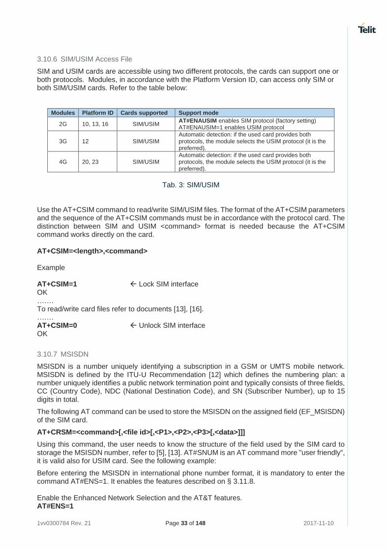
3.10.6 SIM/USIM Access File
SIM and USIM cards are accessible using two different protocols, the cards can support one or both protocols. Modules, in accordance with the Platform Version ID, can access only SIM or both SIM/USIM cards. Refer to the table below:
Modules Platform ID Cards supported Support mode
2G 10, 13, 16 SIM/USIM AT#ENAUSIM enables SIM protocol (factory setting) AT#ENAUSIM=1 enables USIM protocol
3G 12 SIM/USIM Automatic detection: if the used card provides both protocols, the module selects the USIM protocol (it is the preferred).
4G 20, 23 SIM/USIM Automatic detection: if the used card provides both protocols, the module selects the USIM protocol (it is the preferred).
Tab. 3: SIM/USIM
Use the AT+CSIM command to read/write SIM/USIM files. The format of the AT+CSIM parameters and the sequence of the AT+CSIM commands must be in accordance with the protocol card. The distinction between SIM and USIM <command> format is needed because the AT+CSIM command works directly on the card. AT+CSIM=<length>,<command> Example AT+CSIM=1 Lock SIM interface OK ……. To read/write card files refer to documents [13], [16]. ……. AT+CSIM=0 Unlock SIM interface OK
3.10.7 MSISDN
MSISDN is a number uniquely identifying a subscription in a GSM or UMTS mobile network. MSISDN is defined by the ITU-U Recommendation [12] which defines the numbering plan: a number uniquely identifies a public network termination point and typically consists of three fields, CC (Country Code), NDC (National Destination Code), and SN (Subscriber Number), up to 15 digits in total.
The following AT command can be used to store the MSISDN on the assigned field (EF_MSISDN) of the SIM card.
AT+CRSM=<command>[,<file id>[,<P1>,<P2>,<P3>[,<data>]]]
Using this command, the user needs to know the structure of the field used by the SIM card to storage the MSISDN number, refer to [5], [13]. AT#SNUM is an AT command more "user friendly", it is valid also for USIM card. See the following example:
Before entering the MSISDN in international phone number format, it is mandatory to enter the command AT#ENS=1. It enables the features described on § 3.11.8. Enable the Enhanced Network Selection and the AT&T features. AT#ENS=1
1vv0300784 Rev. 21 Page 34 of 148 2017-11-10
OK Write phone number and memo string. AT#SNUM=1,"+393X912Y45Z7","MY NUMBER" OK If the features activated with AT#ENS=1 are no longer needed, enter the command AT#ENS=0. AT#ENS=0 OK Read phone number and memo string AT+CNUM +CNUM: "MY NUMBER","+393X912Y45Z7",145 OK
1vv0300784 Rev. 21 Page 35 of 148 2017-11-10
3.11 Network Information
3.11.1 Network Status
Use the following command to enable/disable network registration reports. The command syntax is: AT+CREG[=[<mode>]] Enter the following AT command to verify if the module is registered on a network. The command syntax is: AT+CREG?
3.11.1.1 2G Modules
Check if the module is registered. AT+CREG? +CREG: 0,1 yes, it is registered. OK Now, disconnect the antenna from the module and enter again the command. AT+CREG? +CREG: 0,3 registration denied. OK Connect again the antenna to the module, and select the Network Registration Report format: Local Area Code and Cell Id. AT+CREG=2 OK AT+CREG? +CREG: 2,1,55FA,12EB OK Now, enter a wrong parameter just to see the result format when Verbose Extended Error result is enabled. AT+CREG=9 +CME ERROR: operation not supported
3.11.1.2 3G Modules
Suppose that 2G and 3G technologies are present on the air. Set the module in 2G mode. AT+WS46=12 OK Select the Network Registration Report format: Local Area Code and Cell Id: AT+CREG=2 OK AT+CREG? +CREG: 2,1,"D5BD","520F",0 OK Now, use the command AT+WS46=22 or AT+WS46=25 to set the module in 3G mode. AT+WS46=25
1vv0300784 Rev. 21 Page 36 of 148 2017-11-10
OK Select the Network Registration Report format: Local Area Code and Cell Id: AT+CREG=2 OK AT+CREG? +CREG: 2,1,"EF8D","52D2388",2 OK
3.11.1.3 4G Modules
Model identification AT+CGMM LE910-EU1 OK Enter Test command to know the <mode> range. AT+CREG=? +CREG: (0-2) OK Select the network registration report format <mode>=2. AT+CREG=2 OK Read network registration report AT+CREG? +CREG: 2,1,"3AA3","AAFC43D",7 OK Select the network registration report format <mode>=1. AT+CREG=1 OK Read network registration report AT+CREG? +CREG: 1,1 OK
3.11.2 Network Operator Identification
The following command executes an attempt to select and register the network operator. <mode> parameter defines whether the operator selection is done automatically or it is established using the operator identified by <oper> parameter. AT+COPS=[<mode>[,<format>[,<oper>]]] Use the command shown below to query the module for Network Operators Identifications.
1vv0300784 Rev. 21 Page 37 of 148 2017-11-10
AT+COPS=? To have more information on the command refer to documents [1], [17], [26], and [27] according
to the used module.
3.11.2.1 2G Modules
Assume that the module is registered on a network. AT+COPS=? +COPS: (2,"I TIM",,"22201"),(1,"MOBITEL",,"29341"),(3,"I WIND",,"22288"),(3,"vodafone IT",,"22210"),(1,"Si.mobil",,"29340"),(1,"SI TUSMOBIL",,"29370"),,(0-4),(0,2) OK Now, disconnect the antenna and assume that Verbose Extended Error result is enabled. Enter again the previous AT command. AT+COPS=? +CME ERROR: no network service
3.11.2.2 3G Modules
Assume that 2G and 3G technologies are present on the air. Set the module in 2G mode. AT+WS46=12 OK Check if the module is in 2G mode. AT+COPS? +COPS: 0,0,"I TIM",0 yes, it is in 2G mode OK Collect information about 2G networks. AT+COPS=? +COPS: (2,"I TIM",,"22201",0),(1,"SI MOBITEL GSM",,"29341",0),(3,"I WIND",,"2228 8",0),(1,"SI VEGA 070",,"29370",0),(1,"SI.MOBIL",,"29340",0),,(0-4),(0,2) OK Now, use the command AT+WS46=22 or AT+WS46=25 to set the module in 3G mode. AT+WS46=25 OK Check if the module is in 3G mode AT+COPS? +COPS: 0,0,"I TIM",2 yes, it is in 3G mode OK Collect information about 3G and 2G networks. AT+COPS=? +COPS: (2,"I TIM",,"22201",2),(2,"I TIM",,"22201",0),(1,"SI MOBITEL GSM",,"29341 ",0),(3,"I WIND",,"22288",2),(1,"SI.MOBIL",,"29340",0),(1,"3 ITA",,"22299",2),(3,"I WIND",,"22288",0),(1,"SI VEGA 070",,"29370",0),,(0-4),(0,2) OK
1vv0300784 Rev. 21 Page 38 of 148 2017-11-10
3.11.2.3 4G Modules
Model identification AT+CGMM LE910-EU1 OK Check which technology the module can use. AT+WS46? +WS46: 30 GERAN and E-UTRAN OK Check the current technology the module is using. AT+COPS? +COPS: 0,0,"I TIM",7 E-UTRAN OK List the operators present on the air. AT+COPS=? +COPS: (2,"I TIM",,"22201",7),(1,"I TIM",,"22201",0),(1,"MOBITEL",,"29341",0),(1,"3 ITA",,"22299",7),(3,"vodafone IT",,"22210",7),(1,"I 50",,"22250",7),(3,"I WIND",,"22288",7),(3,"vodafone IT",,"22210",0),(3,"I WIND",,"22288",0),(1,"Si.mobil",,"29340",0),,(0-4),(0,2) OK
1vv0300784 Rev. 21 Page 39 of 148 2017-11-10
3.11.3 Preferred Network Operator List
Use the following AT command to manage the Preferred Operator List stored on SIM. AT+CPOL=[<index>] … The AT+CPOL command has a different set of parameters in accordance with the module type. See the following two sub-chapters.
3.11.3.1 2G Modules
Use the following AT command to manage the Preferred Operator List stored on SIM. The command syntax is: AT+CPOL=[<index>][,<format>[,<oper>]] Check the supported number of operators in the SIM Preferred Operator List and the format: AT+CPOL=? +CPOL: (1-20),(2) The used SIM supports 20 positions; the supported format (2) is numeric OK Reading the entire list: AT+CPOL? +CPOL: 1,2,"20801" +CPOL: 2,2,"20810" +CPOL: 3,2,"23205" +CPOL: 4,2,"22802" +CPOL: 5,2,"29341" …. +CPOL: 19,2,"23802" +CPOL: 20,2,"24201" OK The meaning of the string "XXXYY" is: - XXX = Mobile Country Code
- YY = Mobile Network Code Delete the first entry using a non-existent <format> value just to see the response when the verbose format of the report result code is enabled. AT+CPOL=1,3 +CME ERROR: operation not supported Now, delete the first entry using the right <format> value. AT+CPOL=1,2 OK Check if the first entry is deleted. AT+CPOL? +CPOL: 2,2,"20810" +CPOL: 3,2,"23205" …. +CPOL: 19,2,"23802" +CPOL: 20,2,"24201"
1vv0300784 Rev. 21 Page 40 of 148 2017-11-10
OK The entry on first position is deleted. Write a new entry in the first position. AT+CPOL=1,2,20801 OK Check if the new entry is written on first position: AT+CPOL? +CPOL: 1,2,"20801" The new entry is written on first position +CPOL: 2,2,"20810" …. +CPOL: 20,2,"24201" OK
3.11.3.2 3G Modules
Use the following AT command to manage the Preferred Operator List stored on SIM. The command syntax is: AT+CPOL=[<index>][,<format>[,<oper>[,<GSM_AcT>,<GSM_Compact_AcT>,<UTRAN_Ac
T>]]] Check the supported number of operators in the SIM preferred operator list and the format: AT+CPOL=? +CPOL: (1-35),(2) The used SIM supports 35 positions; the supported format (2) is numeric OK Reading the entire list: AT+CPOL? +CPOL: 1,2,"20801",1,0,1 +CPOL: 2,2,"21407",1,0,1 … +CPOL: 35,2,"73001",1,0,1 OK
3.11.3.3 4G Modules
Use the following AT command to manage the Preferred Operator List stored on SIM. The command syntax is: AT+CPOL=[<index>][,<format>[,<oper>[,<GSM_AcT>,<GSM_Compact_AcT>,<UTRAN_Ac
T>,<EUTRAN_AcT>]]] Check the supported number of operators in the SIM preferred operator list and the format: AT+CPOL=? +CPOL: (1-35),(2) The used SIM supports 35 positions; the supported format (2) is numeric OK Reading the entire list: AT+CPOL? AT+CPOL? +CPOL: 1,2,"23203",1,0,1,0
1vv0300784 Rev. 21 Page 41 of 148 2017-11-10
+CPOL: 2,2,"20610",1,0,1,0 +CPOL: 3,2,"28405",1,0,1,0 +CPOL: 4,2,"23002",1,0,1,0 +CPOL: 5,2,"23820",1,0,1,0 .... +CPOL: 23,2,"24001",1,0,1,0 +CPOL: 24,2,"22801",1,0,1,0 +CPOL: 25,2,"28603",1,0,1,0 +CPOL: 26,2,"23410",1,0,1,0 OK
3.11.4 Signal Strength & Quality
Assume that the module is registered on a network (2G, 3G, or 4G technology). The following AT command returns the received signal strength (<rssi>) and quality (<ber>), giving an indication about the radio link reliability. The command syntax is: AT+CSQ Assume that the antenna is not connected to the module or network coverage is not present at all. AT+CSQ +CSQ: 99,99 OK Now, the antenna is connected to the module and network coverage is present. Enter again the previous AT command: AT+CSQ +CSQ: 17,0 17 = <rssi> = Received Signal Strength Indication OK 0 = <ber> = Bit Error Rate Now, a wrong parameter is entered just to see the result format when the verbose format of the report result code is enabled. AT+CSQ? +CME ERROR: operation not supported
3.11.5 Fast Network Status Check
Once the module is registered on a network, does not matter about the technology (2G or 3G), it is useful to know the received signal strength and the network on which the module is registered. This information is gathered by means of the following standard AT commands: +CREG, +COPS and +CSQ. These commands are not fast in the response due to network response time, especially the +COPS command. If the user objective is to keep his application as general as possible, he can use the standard. Telit's modules provide proprietary AT commands to gather all the information in a faster and simpler way, they are:
• AT#MONI
• AT#SERVINFO
1vv0300784 Rev. 21 Page 42 of 148 2017-11-10
AT#MONI and AT#SERVINFO commands should be used only to collect network name and signal strength information. To check if the module is registered or it is looking for a suitable network to register on, use +CREG command. In fact, if the network signal is too weak and module loses the registration, until a new network is found the two commands report the last measured valid values and not the real ones. The TA (timing advance parameter) is valid only during a call. Check network registration with +CREG command. When module is registered, query the module for network operator name and signal strength with AT#MONI command.
3.11.5.1 2G Modules
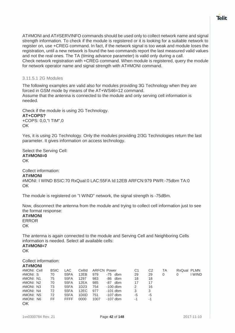
The following examples are valid also for modules providing 3G Technology when they are forced in GSM mode by means of the AT+WS46=12 command. Assume that the antenna is connected to the module and only serving cell information is needed. Check if the module is using 2G Technology. AT+COPS? +COPS: 0,0,"I TIM",0 OK Yes, it is using 2G Technology. Only the modules providing 2/3G Technologies return the last parameter. It gives information on access technology. Select the Serving Cell: AT#MONI=0 OK Collect information: AT#MONI #MONI: I WIND BSIC:70 RxQual:0 LAC:55FA Id:12EB ARFCN:979 PWR:-75dbm TA:0 OK The module is registered on "I WIND" network, the signal strength is -75dBm. Now, disconnect the antenna from the module and trying to collect cell information just to see the format response: AT#MONI ERROR OK The antenna is again connected to the module and Serving Cell and Neighboring Cells information is needed. Select all available cells: AT#MONI=7 OK Collect information: AT#MONI #MONI: Cell BSIC LAC CellId ARFCN Power C1 C2 TA RxQual PLMN #MONI: S 70 55FA 12EB 979 -75 dbm 29 29 0 0 I WIND #MONI: N1 75 55FA 1297 983 -86 dbm 18 18 #MONI: N2 70 55FA 12EA 985 -87 dbm 17 17 #MONI: N3 73 55FA 1D23 754 -100 dbm 2 16 #MONI: N4 72 55FA 12EC 977 -101 dbm 3 3 #MONI: N5 72 55FA 1D0D 751 -107 dbm -5 -5 #MONI: N6 FF FFFF 0000 1007 -107 dbm -1 -1
OK
1vv0300784 Rev. 21 Page 43 of 148 2017-11-10
Collect only the Serving Cell network Information. AT#SERVINFO #SERVINFO: 979,-75,"I WIND","22288",70,55FA,00,1,,"II",01,6
3.11.5.2 3G Modules
Suppose that the 3G Technology is present on the air. Use the command AT+WS46=22 or AT+WS46=25 to set the module in 3G mode. Examples Check if the module is using 3G Technology: AT+COPS? +COPS: 0,0,"I TIM",2 OK Yes, it is using 3G Technology. Select the Serving Cell: AT#MONI=0 OK Collect information: AT#MONI #MONI: I TIM PSC:49 RSCP:-102 LAC:EF8D Id:52D2388 EcIo:-2.5 UARFCN:10638 PWR:-97 dbm DRX:64 SCR:784
OK Use the following AT command to collect only the Serving Cell Information: AT#SERVINFO #SERVINFO: 10638,-94,"I TIM","22201",49,EF8D,64,3,-101,"II",00 OK Use this command to get the current network status. AT#RFSTS #RFSTS: "222 01",10638,49,-5.0,-95,-85,EF8D,00,-128,128,19,4,2,,52D2388,"2220102413217","I TIM",3,0
OK
3.11.5.3 4G Modules
Check the currently selected cellular network. AT+WS46? +WS46: 30 GERAN and E-UTRAN OK Check if the module is using 4G Technology: AT+COPS? +COPS: 0,0,"I TIM",7 E-UTRAN OK Select the Serving Cell: AT#MONI=0 OK
1vv0300784 Rev. 21 Page 44 of 148 2017-11-10
Collect information: AT#MONI #MONI: I TIM RSRP:-69 RSRQ:-7.0 TAC:3AA3 Id:AAFC43D EARFCN:6300 PWR:-40dbm DRX:128 pci:121
QRxLevMin:10
OK Use the following AT command to collect only the Serving Cell Information: AT#SERVINFO #SERVINFO: 6300,-41,"I TIM","22201",0000079,3aa3,FF,3,-69 OK Use this command to get the current network status. AT#RFSTS #RFSTS: "222 01",6300,-67,-39,-6.5,3aa3,FF,0,0,19,1,"AAFC43D","222015602268634","I TIM",3,20,720,3240
OK
3.11.6 Network Survey
Use the following AT command to perform a quick survey of the channels belonging to the current band, refer to [20]. The command syntax is: AT#CSURV [=<s>,<e>] Example for 2G Modules AT#BND? #BND: 0 GSM 900 MHz + DCS 1800 MHz OK AT#CSURV=4,8 Network survey started … arfcn: 7 bsic: 18 rxLev: -78 ber: 0.00 mcc: 222 mnc: 01 lac: 54717 cellId: 21007 cellStatus:
CELL_SUITABLE numArfcn: 3 arfcn: 7 13 27 arfcn: 4 bsic: 16 rxLev: -85 ber: 0.00 mcc: 222 mnc: 01 lac: 54717 cellId: 21094 cellStatus:
CELL_SUITABLE numArfcn: 2 arfcn: 4 1021 arfcn: 8 rxLev: -92 arfcn: 6 rxLev: -93 arfcn: 5 rxLev: -98 Network survey ended OK
To have detailed information on the command, refer to documents [1], [17], and [26], according to the used module. LE866/ME866A1 do not provide #CSURV command.
1vv0300784 Rev. 21 Page 45 of 148 2017-11-10
3.11.7 BCCH Survey
Use the following AT command to perform a quick survey of the channels belonging to the current band. The survey stops as soon as <n> BCCH carriers are found. AT#CSURVB = [<n>] Example for 2G Modules AT#CSURVB=2 Network survey started … arfcn: 104 bsic: 63 rxLev: -68 ber: 0.00 mcc: 222 mnc: 88 lac: 22010 cellId: 4737 cellStatus:
CELL_FORBIDDEN numArfcn: 3 arfcn: 114 989 995 arfcn: 761 bsic: 57 rxLev: -72 ber: 0.00 mcc: 222 mnc: 88 lac: 22010 cellId: 7437 cellStatus:
CELL_FORBIDDEN numArfcn: 4 arfcn: 776 785 794 803 Network survey ended OK
3G/4G Modules do not provide this command.
1vv0300784 Rev. 21 Page 46 of 148 2017-11-10
3.11.8 ENS, OMA-DM, and AT&T functions
Use the following AT command to enable/disable the Enhanced Network Selection and the AT&T features. ENS works if the module and the SIM card are both ENS-capable. The command syntax is: AT#ENS=[<mode>] AT#ENS? #ENS: 0 factory setting Using the factory setting, the module follows the European Standard R98/R4/R7. Enter the following setting, and power OFF/ON the module to make active the new setting. AT#ENS=1 OK The following chapters describe the features enabled by the #ENS command.
3.11.8.1 2G Modules SW Ver. ≥ 10.00.xx5/16.00.xx2
3.11.8.1.1 No AT&T SIM Card
• EONS features (refer to [9], § 15)
• ENS features for network selection (refer to [9], §13)
• special requirements for USSD strings (refer to [9], <CDR-GSM-255>)
• special ATD dial string format (ATDxxxxxPyyyyyy), refer to [9] <CDR-CON-3074>, <CDR-CON-3342>;
• 10.00.xx5 if #AUTOBND=0 then, automatically, #AUTOBND is forced to 1. If #AUTOBND=2 (factory setting) no action is taken.
• >= 10.00.xx6/16.00.xx2 if #AUTOBND=0 then, automatically, #AUTOBND is forced to 2. If #AUTOBND=2 (factory setting) no action is taken.
• +PACSP AT command to display the PLMN Mode Bit read from CPHS file on SIM (refer to [9])
• AT#STIA=2,1 as default
• the max length of the telephone number that can be stored in SIM phonebooks is greater than the default value (20)
• AT#PLMNMODE=1 as default
• different coding and encoding for MCC and MNC for SAT functions (refer to [9])
• MWI messages (refer to [9], §16)
1vv0300784 Rev. 21 Page 47 of 148 2017-11-10
3.11.8.1.2 AT&T SIM card Assume that #ENS=1. The module supports the features indicated in § 3.11.8.1.1, plus the following:
• Acting Home PLMN (refer to [9], § 12) When AT#ENS=1, it is recommended to use the following setting: AT#AUTOBND=2 AT#NITZ=7,X (X if the user wants the URC) AT#SMSMODE=1 Regardless the SIM card used, the module supports the following features in accordance with the #ENS setting:
• Concerning Phonebook string management:
#ENS=1
BCD format conversion ASCII format
0x0D (wild char) ?
? 0x0D (wild char)
0x0C P
0x0C p
#ENS=0
BCD format conversion ASCII format
0x0D (wild char) @
@ 0x0D (wild char)
0x0C P
• #ENS=1: USSD MT event is notified via the tone associated to an SMS MT. If #ENS=0, the event is not notified via the tone, but is notified via an unsolicited message (if it is enabled).
• #ENS=1: the default GSM band parameter of #BND AT command is 3. If #ENS=0, the default GSM band parameter is 0.
• #ENS=1: #BND=1 or #BND=2 are not permitted. If #ENS=0, they are permitted.
• #ENS=1: ATD 0; and ATD 00; AT commands execute a call to the phone number 0 and 00 respectively. If #ENS=0, 0 and 00 are interpreted as USSD strings and sent to the network.
• #ENS=1: enter AT+CLCK="FD",1,PIN2 AT command to select the FD phonebook as current phonebook. If #ENS=0, enter the following commands: AT+CPIN=PIN2 OK AT+CPBS="FD" OK In alternative of the previous two AT commands, the following one can be used: AT+CLCK="FD",1,PIN2
1vv0300784 Rev. 21 Page 48 of 148 2017-11-10
• #ENS=1: after activating the context via AT+CGACT=1,<cid>, the DNS information is not received. Enter ATD*99***1# to execute the dial up. If #ENS=0, after activating the context via AT+CGACT=1,<cid>, the DNS information is received. Enter ATD*99***1# to execute the dial up.
3.11.8.2 2G Modules SW Ver. ≥ 13.00.xx2
3.11.8.2.1 No AT&T SIM cards
The module supports the following features independently from the #ENS setting:
• EONS features (refer to [9], § 15)
• special requirements for USSD strings (refer to [9], <CDR-GSM-255>
• special ATD dial string format (ATDxxxxxPyyyyyy), refer to [9] <CDR-CON-3074>, <CDR-CON-3342>;
• +PACSP AT command to display the PLMN Mode Bit read from CPHS file on SIM (refer to [9])
• the max length of the telephone number that can be stored in SIM phonebooks is greater than the default value (20)
The module supports the following features when #ENS=1:
• If #AUTOBND=0 then, automatically, #AUTOBND is forced to 2. If #AUTOBND=2 (factory setting) no action is taken.
• AT#BND supports only values 0 and 3
• AT#STIA=2,1 as default
• different coding and encoding for MCC and MNC for SAT functions (refer to [9])
• MWI messages (refer to [9], §16)
• ENS features for Network selection (refer to [9], §13)
• AT#PLMNMODE=1 as default
3.11.8.2.2 AT&T SIM card Assume that #ENS=1. The module supports the features indicated in § 3.11.8.2.1, plus the following:
• Acting Home PLMN (refer to [9], § 12) When AT#ENS=1, it is recommended to use the following setting: AT#AUTOBND=2 AT#NITZ=7,X (X if the user wants the URC) AT#SMSMODE=1 Regardless the SIM card used, the module supports the following features in accordance with the #ENS setting:
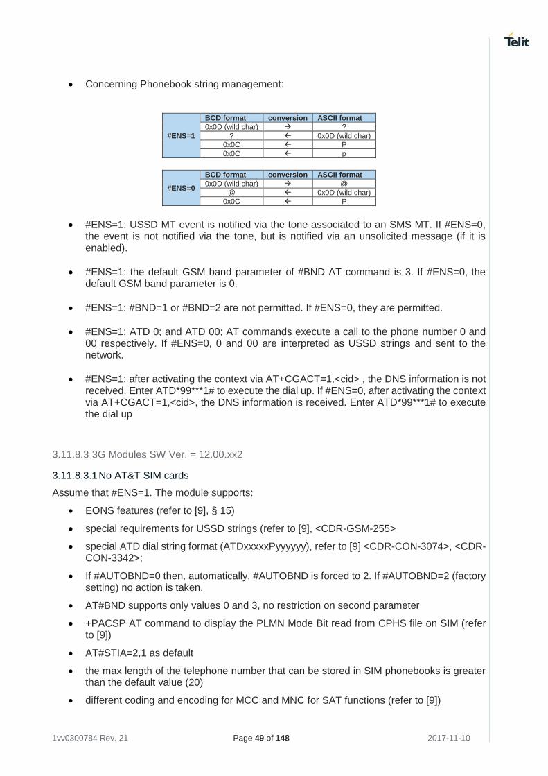
1vv0300784 Rev. 21 Page 49 of 148 2017-11-10
• Concerning Phonebook string management:
#ENS=1
BCD format conversion ASCII format
0x0D (wild char) ?
? 0x0D (wild char)
0x0C P
0x0C p
#ENS=0
BCD format conversion ASCII format
0x0D (wild char) @
@ 0x0D (wild char)
0x0C P
• #ENS=1: USSD MT event is notified via the tone associated to an SMS MT. If #ENS=0, the event is not notified via the tone, but is notified via an unsolicited message (if it is enabled).
• #ENS=1: the default GSM band parameter of #BND AT command is 3. If #ENS=0, the default GSM band parameter is 0.
• #ENS=1: #BND=1 or #BND=2 are not permitted. If #ENS=0, they are permitted.
• #ENS=1: ATD 0; and ATD 00; AT commands execute a call to the phone number 0 and 00 respectively. If #ENS=0, 0 and 00 are interpreted as USSD strings and sent to the network.
• #ENS=1: after activating the context via AT+CGACT=1,<cid> , the DNS information is not received. Enter ATD*99***1# to execute the dial up. If #ENS=0, after activating the context via AT+CGACT=1,<cid>, the DNS information is received. Enter ATD*99***1# to execute the dial up
3.11.8.3 3G Modules SW Ver. = 12.00.xx2
3.11.8.3.1 No AT&T SIM cards
Assume that #ENS=1. The module supports:
• EONS features (refer to [9], § 15)
• special requirements for USSD strings (refer to [9], <CDR-GSM-255>
• special ATD dial string format (ATDxxxxxPyyyyyy), refer to [9] <CDR-CON-3074>, <CDR-CON-3342>;
• If #AUTOBND=0 then, automatically, #AUTOBND is forced to 2. If #AUTOBND=2 (factory setting) no action is taken.
• AT#BND supports only values 0 and 3, no restriction on second parameter
• +PACSP AT command to display the PLMN Mode Bit read from CPHS file on SIM (refer to [9])
• AT#STIA=2,1 as default
• the max length of the telephone number that can be stored in SIM phonebooks is greater than the default value (20)
• different coding and encoding for MCC and MNC for SAT functions (refer to [9])
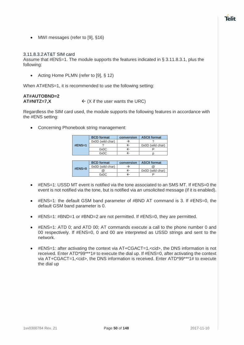
1vv0300784 Rev. 21 Page 50 of 148 2017-11-10
• MWI messages (refer to [9], §16)
3.11.8.3.2 AT&T SIM card Assume that #ENS=1. The module supports the features indicated in § 3.11.8.3.1, plus the following:
• Acting Home PLMN (refer to [9], § 12) When AT#ENS=1, it is recommended to use the following setting: AT#AUTOBND=2 AT#NITZ=7,X (X if the user wants the URC) Regardless the SIM card used, the module supports the following features in accordance with the #ENS setting:
• Concerning Phonebook string management:
#ENS=1
BCD format conversion ASCII format
0x0D (wild char) ?
? 0x0D (wild char)
0x0C P
0x0C p
#ENS=0
BCD format conversion ASCII format
0x0D (wild char) @
@ 0x0D (wild char)
0x0C P
• #ENS=1: USSD MT event is notified via the tone associated to an SMS MT. If #ENS=0 the event is not notified via the tone, but is notified via an unsolicited message (if it is enabled).
• #ENS=1: the default GSM band parameter of #BND AT command is 3. If #ENS=0, the default GSM band parameter is 0.
• #ENS=1: #BND=1 or #BND=2 are not permitted. If #ENS=0, they are permitted.
• #ENS=1: ATD 0; and ATD 00; AT commands execute a call to the phone number 0 and 00 respectively. If #ENS=0, 0 and 00 are interpreted as USSD strings and sent to the network.
• #ENS=1: after activating the context via AT+CGACT=1,<cid>, the DNS information is not received. Enter ATD*99***1# to execute the dial up. If #ENS=0, after activating the context via AT+CGACT=1,<cid>, the DNS information is received. Enter ATD*99***1# to execute the dial up
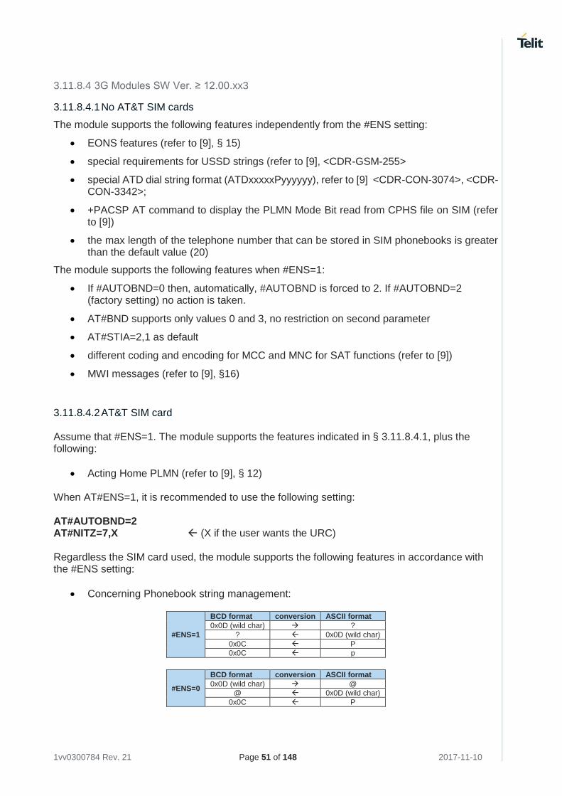
1vv0300784 Rev. 21 Page 51 of 148 2017-11-10
3.11.8.4 3G Modules SW Ver. ≥ 12.00.xx3
3.11.8.4.1 No AT&T SIM cards
The module supports the following features independently from the #ENS setting:
• EONS features (refer to [9], § 15)
• special requirements for USSD strings (refer to [9], <CDR-GSM-255>
• special ATD dial string format (ATDxxxxxPyyyyyy), refer to [9] <CDR-CON-3074>, <CDR-CON-3342>;
• +PACSP AT command to display the PLMN Mode Bit read from CPHS file on SIM (refer to [9])
• the max length of the telephone number that can be stored in SIM phonebooks is greater than the default value (20)
The module supports the following features when #ENS=1:
• If #AUTOBND=0 then, automatically, #AUTOBND is forced to 2. If #AUTOBND=2 (factory setting) no action is taken.
• AT#BND supports only values 0 and 3, no restriction on second parameter
• AT#STIA=2,1 as default
• different coding and encoding for MCC and MNC for SAT functions (refer to [9])
• MWI messages (refer to [9], §16)
3.11.8.4.2 AT&T SIM card Assume that #ENS=1. The module supports the features indicated in § 3.11.8.4.1, plus the following:
• Acting Home PLMN (refer to [9], § 12) When AT#ENS=1, it is recommended to use the following setting: AT#AUTOBND=2 AT#NITZ=7,X (X if the user wants the URC) Regardless the SIM card used, the module supports the following features in accordance with the #ENS setting:
• Concerning Phonebook string management:
#ENS=1
BCD format conversion ASCII format
0x0D (wild char) ?
? 0x0D (wild char)
0x0C P
0x0C p
#ENS=0
BCD format conversion ASCII format
0x0D (wild char) @
@ 0x0D (wild char)
0x0C P
1vv0300784 Rev. 21 Page 52 of 148 2017-11-10
• #ENS=1: USSD MT event is notified via the tone associated to an SMS MT. If #ENS=0, the event is not notified via the tone, but is notified via an unsolicited message (if it is enabled).
• #ENS=1: the default GSM band parameter of #BND AT command is 3. If #ENS=0, the default GSM band parameter is 0.
• #ENS=1: #BND=1 or #BND=2 are not permitted. If #ENS=0, they are permitted.
• #ENS=1: ATD 0; and ATD 00; AT commands execute a call to the phone number 0 and 00 respectively. If #ENS=0, 0 and 00 are interpreted as USSD strings and sent to the network.
• #ENS=1: AT+CFUN=0 is the same of AT+CFUN=4. If #ENS=0, +CFUN=0 and +CFUN=4 have the standard behavior.
• #ENS=1: the Radio Policy Management (RPM) is supported. If #ENS=0, RPM is not supported.
• #ENS=1: the default class parameter is 12 (AT#MSCLASS=12). If #ENS=0, the default class parameter is 33.
• #ENS=1: the following CPC features are disabled:
-HSPA and HSPA+ 7.4 HSPA+ <CDR-HSD-491> UL DPCCH Gating (Uplink DTX) -HSPA and HSPA+ 7.4 HSPA+ <CDR-HSD-492> E-DCH Tx Start Timer Restriction (Uplink DRX) -HSPA and HSPA+ 7.4 HSPA+ <CDR-HSD-493> Downlink DRX -HSPA and HSPA+ 7.4 HSPA+ <CDR-HSD-494> New UL DPCCH Slot Format -HSPA and HSPA+ 7.4 HSPA+ <CDR-HSD-496> CQI Reporting Reduction If #ENS=0, the features are enabled.
• #ENS=1: after power on the module executes the SIM reading and the network registration in sequential way. The call establishment is immediately available after the network registration. If #ENS=0, the module executes the SIM reading and the network registration in parallel. It can happen that the module is registered, but the reading SIM is not ended, for this reason wait for some seconds after network registration before calling.
• #ENS=1: after activating the context via AT+CGACT=1,<cid> commands, the DNS information is not received. Enter ATD*99***1# to execute the dial up. If #ENS=0, after activating the context via AT+CGACT=1,<cid> commands, the DNS information is received. Enter ATD*99***1# to execute the dial up
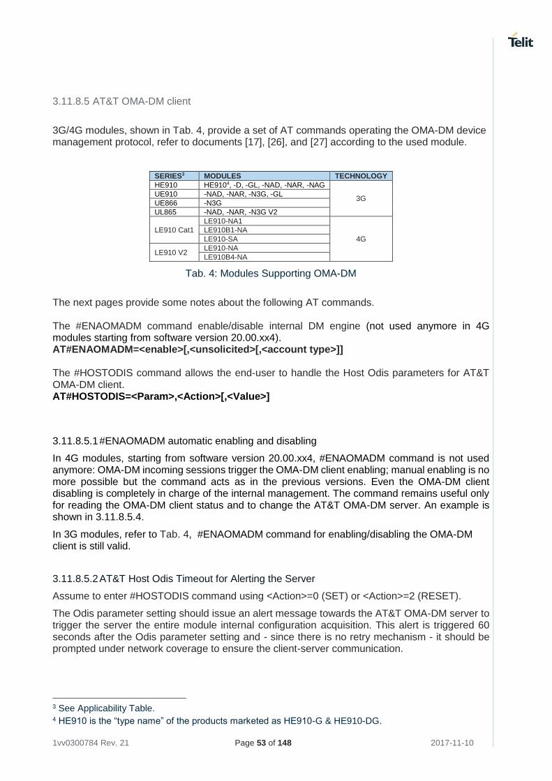
1vv0300784 Rev. 21 Page 53 of 148 2017-11-10
3.11.8.5 AT&T OMA-DM client
3G/4G modules, shown in Tab. 4, provide a set of AT commands operating the OMA-DM device management protocol, refer to documents [17], [26], and [27] according to the used module.
SERIES3 MODULES TECHNOLOGY
HE910 HE9104, -D, -GL, -NAD, -NAR, -NAG
3G UE910 -NAD, -NAR, -N3G, -GL
UE866 -N3G
UL865 -NAD, -NAR, -N3G V2
LE910 Cat1
LE910-NA1
4G
LE910B1-NA
LE910-SA
LE910 V2 LE910-NA
LE910B4-NA
Tab. 4: Modules Supporting OMA-DM
The next pages provide some notes about the following AT commands. The #ENAOMADM command enable/disable internal DM engine (not used anymore in 4G modules starting from software version 20.00.xx4). AT#ENAOMADM=<enable>[,<unsolicited>[,<account type>]] The #HOSTODIS command allows the end-user to handle the Host Odis parameters for AT&T OMA-DM client. AT#HOSTODIS=<Param>,<Action>[,<Value>]
3.11.8.5.1 #ENAOMADM automatic enabling and disabling
In 4G modules, starting from software version 20.00.xx4, #ENAOMADM command is not used anymore: OMA-DM incoming sessions trigger the OMA-DM client enabling; manual enabling is no more possible but the command acts as in the previous versions. Even the OMA-DM client disabling is completely in charge of the internal management. The command remains useful only for reading the OMA-DM client status and to change the AT&T OMA-DM server. An example is shown in 3.11.8.5.4.
In 3G modules, refer to Tab. 4, #ENAOMADM command for enabling/disabling the OMA-DM client is still valid.
3.11.8.5.2 AT&T Host Odis Timeout for Alerting the Server
Assume to enter #HOSTODIS command using <Action>=0 (SET) or <Action>=2 (RESET).
The Odis parameter setting should issue an alert message towards the AT&T OMA-DM server to trigger the server the entire module internal configuration acquisition. This alert is triggered 60 seconds after the Odis parameter setting and - since there is no retry mechanism - it should be prompted under network coverage to ensure the client-server communication.
3 See Applicability Table. 4 HE910 is the “type name” of the products marketed as HE910-G & HE910-DG.
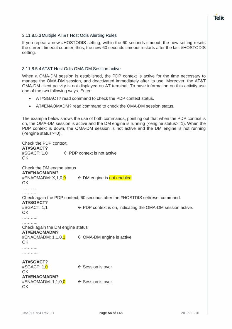
1vv0300784 Rev. 21 Page 54 of 148 2017-11-10
3.11.8.5.3 Multiple AT&T Host Odis Alerting Rules
If you repeat a new #HOSTODIS setting, within the 60 seconds timeout, the new setting resets the current timeout counter; thus, the new 60 seconds timeout restarts after the last #HOSTODIS setting.
3.11.8.5.4 AT&T Host Odis OMA-DM Session active
When a OMA-DM session is established, the PDP context is active for the time necessary to manage the OMA-DM session, and deactivated immediately after its use. Moreover, the AT&T OMA-DM client activity is not displayed on AT terminal. To have information on this activity use one of the two following ways. Enter:
• AT#SGACT? read command to check the PDP context status.
• AT#ENAOMADM? read command to check the OMA-DM session status.
The example below shows the use of both commands, pointing out that when the PDP context is on, the OMA-DM session is active and the DM engine is running (<engine status>=1). When the PDP context is down, the OMA-DM session is not active and the DM engine is not running (<engine status>=0). Check the PDP context. AT#SGACT? #SGACT: 1,0 PDP context is not active OK Check the DM engine status AT#ENAOMADM? #ENAOMADM: X,1,0,0 DM engine is not enabled OK ………. ………. Check again the PDP context, 60 seconds after the #HOSTDIS set/reset command. AT#SGACT? #SGACT: 1,1 PDP context is on, indicating the OMA-DM session active. OK ……….. ……….. Check again the DM engine status AT#ENAOMADM? #ENAOMADM: 1,1,0,1 OMA-DM engine is active OK ……….. ………... AT#SGACT? #SGACT: 1,0 Session is over OK AT#ENAOMADM? #ENAOMADM: 1,1,0,0 Session is over OK
1vv0300784 Rev. 21 Page 55 of 148 2017-11-10
3.11.8.5.5 AT&T Multiple Host Odis Setting and Memory Management
Assume to use one of the following #HOSTODIS actions:
• #HOSTODIS command using <Action>=2, it selects a #HOSTODIS resetting action
• #HOSTODIS command using <Action>=0, it selects a #HOSTODIS setting action
#HOSTODIS reset command and #HOSTODIS set command save the ODIS parameters in NVM, regardless the value of the new parameters; it is suggested to minimize NVM usage.
3.11.8.5.6 #HOSTODIS Alerting Server trigger
In 4G modules, #HOSTODIS alerting server trigger is present starting from version 20.00.xx4; in earlier versions, even if #HOSTODIS command was present, the alert is not sent.
In 3G modules, #HOSTODIS parameters could be set but no notification is sent to AT&T servers.
3.11.8.5.7 AT&T SIMs with one APN
The NI OMA-DM sessions are automatically managed by the AT&T OMA-DM client, but they need to make use of the PDP context for the OMA-DM client-server connection. Since in 4G the network can reject multiple PDP context on the same APN, and the OMA-DM client has no ability to manage the context if it is already busy (i.e.: by a continuously-connected application that make use of the data context), NI sessions management is not guaranteed in SIMs that have only one APN that is currently in use at the OMA-DM NI SMS arrival.
1vv0300784 Rev. 21 Page 56 of 148 2017-11-10
3.12 Voice Call Establishment – Originate
Before setting up the Voice Call, it is assumed that Telit Module is registered on a network and the signal strength is enough to carry on a reliable radio link. The following sub-chapters introduce AT commands regarding the audio section of the modules. To have detailed information about the audio architecture and the related topics refer to document [18].
3.12.1 Set Module in Voice Mode
Use the following AT command to set up the module for a Voice Call: AT+FCLASS=8 OK
3.12.2 Dialing a Phone Number
Use the following AT command to dial up a phone number. +FCLASS=8 command may be omitted if the ";" modifier is added at the end of the ATD command, after the entered phone number. The command syntax is: ATD<number>[;] Examples Assume that the module is set in voice mode: AT+FCLASS=8 has been executed. After that, call the national number 040-4X92XYX. ATD 0404X92XYX OK Now, call the national number 040-4X92XYX in international format +39-040-4X92XYX. ATD +390404X92XYX OK Call the national number 040-4X92XYX in international format +39-040-4X92XYX. The module is not set in voice mode (AT+FCLASS=8 has not been executed). In this case, to perform the Voice Call you must use the ";" character at the end of the command. ATD +390404X92XYX; OK
3.12.3 Disconnect a Call
Use the following AT command to hang up the current Voice Call: ATH OK
1vv0300784 Rev. 21 Page 57 of 148 2017-11-10
3.12.4 Answering an Incoming Call
When an Incoming Call is recognized, the module sends an Unsolicited Code to DTE. Use the following AT command to answer to the call. ATA OK
3.12.5 Audio Codec Information
Even if the module is registered on 3G/4G network, usually the network operator assigns to the module a GSM channel to carry on a voice call. Use the following AT command to get codec information about the call. AT#CODECINFO = <format>,<mode> OK Example AT#CODECINFO=1,1 enable codec information OK ATD<phone number>; #CODECINFO: "HAMR","FR","EFR","HR","FAMR","HAMR" OK NO CARRIER remote hang up #CODECINFO: "None","FR","EFR","HR","FAMR","HAMR"
3.12.6 Setting Audio Codec
Even if the module is registered on 3G/4G network, usually the network operator assigns to the module a GSM channel to carry on a voice call. Use the following AT command to select a codec during the call. AT#CODEC = <codec> OK Example AT#CODEC? #CODEC: 0 all the codec are enabled OK AT#CODECINFO=1,1 enable codec information OK ATD<phone number>; establish the call #CODECINFO: "HAMR","FR","EFR","HR","FAMR","HAMR" OK NO CARRIER remote hang up #CODECINFO: "None","FR","EFR","HR","FAMR","HAMR" AT#CODEC=1 select FR mode
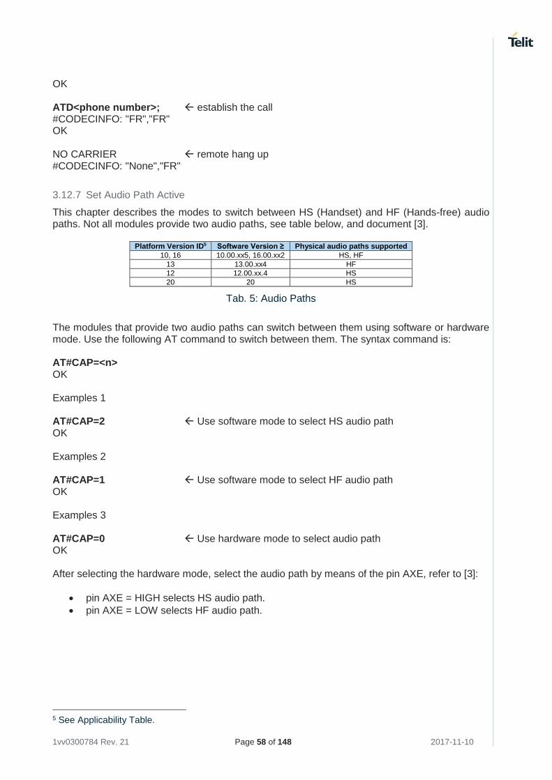
1vv0300784 Rev. 21 Page 58 of 148 2017-11-10
OK ATD<phone number>; establish the call #CODECINFO: "FR","FR" OK NO CARRIER remote hang up #CODECINFO: "None","FR"
3.12.7 Set Audio Path Active
This chapter describes the modes to switch between HS (Handset) and HF (Hands-free) audio paths. Not all modules provide two audio paths, see table below, and document [3].
Platform Version ID5 Software Version ≥ Physical audio paths supported
10, 16 10.00.xx5, 16.00.xx2 HS, HF
13 13.00.xx4 HF
12 12.00.xx.4 HS
20 20 HS
Tab. 5: Audio Paths
The modules that provide two audio paths can switch between them using software or hardware mode. Use the following AT command to switch between them. The syntax command is: AT#CAP=<n> OK Examples 1 AT#CAP=2 Use software mode to select HS audio path OK Examples 2 AT#CAP=1 Use software mode to select HF audio path OK Examples 3 AT#CAP=0 Use hardware mode to select audio path OK After selecting the hardware mode, select the audio path by means of the pin AXE, refer to [3]:
• pin AXE = HIGH selects HS audio path.
• pin AXE = LOW selects HF audio path.
5 See Applicability Table.
1vv0300784 Rev. 21 Page 59 of 148 2017-11-10
The audio paths can be switched also during a call in both ways. When hardware control is not used, AXE pin can be left unconnected.
For modules providing only one audio path, the #CAP is a dummy command. It returns OK response and no actions are performed by the module. It has been introduced for backward compatibility reasons.
3.12.8 Set Volume on Speaker
Use the following AT command to set up the output volume level on the active audio path: AT+CLVL=<vol> OK If the used module provides two audio paths (HS and HF), when moving from one path to the new one, the volume level does not change.
3.12.9 Set Microphone Mute
The following AT command mutes the microphone of the active path: AT+CMUT=1 OK Check the microphone setting: AT+CMUT? +CMUT: 1 OK
3.12.10 Hand Set Path Commands
The Handset (HS) audio path commands described in this section are dummy commands for the modules that do not provide the HS audio path, refer to chapter 3.12.7. The commands return OK response, and no actions are performed by the modules. This solution was adopted for backward compatibility reasons.
3.12.10.1 HS Microphone Gain
Use the following AT command to set up microphone input gain: AT#HSMICG=<n> Examples Check the available gain levels AT#HSMICG=? #HSMICG: (0-7) OK Check the current gain level AT#HSMICG? #HSMICG: 0 OK
1vv0300784 Rev. 21 Page 60 of 148 2017-11-10
Set up a new gain level AT#HSMICG=1 OK
3.12.10.2 HS Sidetone
Use the following AT command to enable/disable the sidetone on HS audio path. AT#SHSSD=<mode> Examples Check the available values AT#SHSSD =? #SHSSD: (0-1) OK Check the current value AT#SHSSD? #SHSSD: 0 OK Enable sidetone AT#SHSSD=1 OK
3.12.10.3 HS Echo Canceller
Use the following AT command to enable/disable the echo canceller function on HS audio path. AT#SHSEC=<mode> Examples Check the available values AT#SHSEC =? #SHSEC: (0-1) OK Check the current value AT#SHSEC? #SHSEC: 0 OK Enable echo canceller function AT#SHSEC=1 OK
3.12.10.4 HS Automatic Gain
Use the following AT command to enable/disable the automatic gain control function on HS audio path. AT#SHSAGC=<mode> Examples
1vv0300784 Rev. 21 Page 61 of 148 2017-11-10
Check the available values AT# SHSAGC =? #SHSAGC: (0-1) OK Check the current value AT# SHSAGC? # SHSAGC: 0 OK Enable automatic gain control function AT# SHSAGC =1 OK
3.12.10.5 HS Noise Reduction
Use the following AT command to enable/disable the noise reduction function on HS audio path. AT#SHSNR=<mode> Examples Check the available values AT# SHSNR =? #SHSNR: (0-1) OK Check the current value AT# SHSNR? # SHSNR: 0 OK Enable the noise reduction function AT# SHSNR =1 OK
3.12.11 Hands Free Path Commands
The Hands-free (HF) audio path commands described in this section are dummy commands for the modules that do not provide the HF audio path, refer to chapter 3.12.7. The commands return OK response, and no actions are performed by the modules. This solution was adopted for backward compatibility reasons.
3.12.11.1 HF Microphone Gain
Use the following AT command to set up the microphone input gain: AT#HFMICG=<n> Examples Check the available gain levels AT#HFMICG=? #HFMICG: (0-7) OK
1vv0300784 Rev. 21 Page 62 of 148 2017-11-10
Check the current gain level AT#HFMICG? #HFMICG: 0 OK Set up a new gain level AT#HFMICG=1 OK
3.12.11.2 HF Sidetone
Use the following AT command to enable/disable the sidetone on HF audio path. AT#SHFSD=<mode> Examples Check the available values AT#SHFSD=? #SHFSD: (0-1) OK Check the current value AT#SHFSD? #SHFSD: 0 OK Enable sidetone AT#SHFSD=1 OK
3.12.11.3 HF Echo Canceller
Use the following AT command to enable/disable the echo canceller function on HF audio path. AT#SHFEC=<mode> Examples Check the available values AT#SHFEC =? #SHFEC: (0-1) OK Check the current value AT#SHFEC? #SHFEC: 0 OK Enable echo canceller function AT#SHFEC=1 OK
1vv0300784 Rev. 21 Page 63 of 148 2017-11-10
3.12.11.4 HF Automatic Gain
Use the following AT command to enable/disable the automatic gain control function on HF audio path. AT#SHFAGC=<mode> Examples Check the available values AT# SHFAGC =? #SHFAGC: (0-1) OK Check the current value AT# SHFAGC? # SHFAGC: 0 OK Enable automatic gain control function AT# SHFAGC =1 OK
3.12.11.5 HF Noise Reduction
Use the following AT command to enable/disable the noise reduction function on HF audio path. AT#SHFNR=<mode> Examples Check the available values AT# SHFNR =? #SHFNR: (0-1) OK Check the current value AT# SHFNR? # SHFNR: 0 OK Enable the noise reduction function AT# SHFNR =1 OK
1vv0300784 Rev. 21 Page 64 of 148 2017-11-10
3.13 CSD Data Call Establishing – Originate
Before setting up the CSD Data Call (not GPRS), it is assumed that the module is registered on a network and the signal strength is enough to carry on a reliable radio link.
3.13.1 Set Module in ONLINE Mode
Use the following AT command to set up the module for a Data Call: AT+FCLASS=0 OK
+FCLASS setting is stored in NVM, so there is no need to repeat this command if +FCLASS setting is not required to change.
3.13.2 Dialing a Phone Number
Use the following AT command to dial a phone number: ATD<number> Examples Call the national number 040-4X92XYX. The module is set in ONLINE Mode (AT+FCLASS=0 has been executed). ATD0404X92XYX CONNECT 9600 Call the national number 040-4X92XYX in international format +39-40-4X92XYX. The module is set in ONLINE Mode (AT+FCLASS=0 has been executed). ATD+39404X92XYX CONNECT 9600 The ATD response is returned when the modem handshake is over; it takes an interval of time depending from several factors (Network Operator, communication speed, etc.). Wait for this time before doing anything: when the module is doing the handshake, entering any character closes the handshake and aborts the call.
3.13.3 Disconnect Data Call
During the data call, the module is in ONLINE Mode, and if any AT command is entered it is discarded and not executed. Before typing in the ATH command to close the call, the escape sequence (+++) must be used to enter the COMMAND Mode. No characters must be entered between two consecutive "+" characters forming the escape sequence.
Assume that a CSD Data Call is in progress. To exit the ONLINE Mode, do the following actions:
• Enter the escape sequence: +++
• Wait for the escape sequence pause time (see ATS12 command, refer to [1]/[17]/[26]/ [27]).
• Wait for the response OK.
Now, the module is in COMMAND Mode. Enter the following command to close the call.
1vv0300784 Rev. 21 Page 65 of 148 2017-11-10
ATH NO CARRIER
3.13.4 Set Modulation and Speed
The Data Connection can be established using different speeds, bearer services, connection element. The connection mode can be selected with the following AT command: AT+CBST[=<speed>[,<name>[,<ce>]]] OK
3.13.4.1 2G Modules
AT+CBST=? Check the supported range +CBST: (0-4,6,7,14,65,66,68,70,71,75),(0),(0,1) OK AT+CBST? Read current values +CBST: 0,0,1 OK AT+CBST=1,0,1 Setting new speed OK AT+CBST? Check if new speed value is set +CBST: 1,0,1 OK
It is recommended to use the Non-Transparent mode to avoid the reception of noise characters.
3.13.4.2 3G Modules
AT+CBST=? Check the supported range +CBST: (0,4-7,12,14-17,68,70,71,75,79-84,115,116,120,121,130-134),(0),(0,1) OK
3.13.5 Modules Supporting Only Data Call
These modules do not feature the capability to manage Mobile Originated and Mobile Terminated Voice calls, they provide Data only: ATD<phone number>; the voice call is not supported NO CARRIER ATA answer to an incoming call is not supported ERROR The following command is supported, but it does not work for an incoming voice calls. The automatic answer is not performed. ATS0=<number of rings> OK
1vv0300784 Rev. 21 Page 66 of 148 2017-11-10
Even though the incoming voice call is not supported, when one is active the RING message is displayed on the DTE. The RING message persists until the call is active. Remind that ATA command is not available and ATS0 command does not work with the incoming voice call. Use the ATH command to drop down the call.
1vv0300784 Rev. 21 Page 67 of 148 2017-11-10
3.14 GSM Single Numbering Scheme
3.14.1 2G Modules
Most Network Operators use a primary phone number associated to the voice service and a secondary phone number to data and fax. If the Operator employs a GSM Single Numbering Scheme, the voice and data number is the same. To select the bearer to be used when a mobile terminated Single Numbering Scheme call is established, use the following AT command. AT+CSNS=<mode> Example 1 AT+CSNS=0 voice (factory default) OK RING RING ATA voice channel is ON Example 2 AT+CSNS=2 data OK RING RING ATA data channel is ON
3.15 TTY Feature
Refer to document [18].
3.16 Software Shutdown
Enter the following AT command to start the module shutdown. AT#SHDN OK During shutdown, the module executes the following actions:
• Detachment from the network
• Module power off To have more information about procedure and timing refer to document [3] in accordance with the module that you are using.
1vv0300784 Rev. 21 Page 68 of 148 2017-11-10
3.17 Call Management
3.17.1 Identifying the Call Type
The module can identify the call type before answering. To accomplish this feature, the module provides different ring indications (URC) depending on the call type. It is up to the user to enable the extended format reporting of incoming calls using the following AT command. AT+CRC=[<mode>] OK Examples Disable extended format reporting, and then assume that the module receives a call. AT+CRC=? Check the range value +CRC: (0,1) OK AT+CRC=0 Disable extended format reporting. OK AT+CRC? +CRC: 0 OK The module detects a call. Ring indications are displayed on DTE: RING RING Now, enable extended format reporting, and then assume the module receives a call. AT+CRC=1 Enable extended format reporting OK AT+CRC? Check if extended format reporting is enabled +CRC: 1 OK The module detects a call. Ring indications in extended format are displayed on DTE: +CRING: VOICE +CRING: VOICE
3.17.2 Identify the Caller
The Telit Module can identify the caller number and give indication about it before the call is answered. The Calling Line Indication is shown on DTE after each RING or +CRING indication. The following AT command is used to enable/disable the Calling Line Indication. AT+CLIP=[<n>] Examples Enable extended format reporting and caller number identification, and then assume to receive a call. Enable extended format reporting.
1vv0300784 Rev. 21 Page 69 of 148 2017-11-10
AT+CRC=1 OK Check if extended format reporting is enabled. AT+CRC? +CRC: 1 OK Check the values range. AT+CLIP? +CLIP: 0,1 OK Enable caller number identification. AT+CLIP=1 OK AT+CLIP? +CLIP: 1,1 OK The module detects a call; ring indications and Calling Line Identification of the calling party are displayed on DTE: +CRING: VOICE +CLIP: "+390404X92XYX",145,"",128,"",0 +CRING: VOICE +CLIP: "+390404X92XYX",145,"",128,"",0
3.17.3 Calling Line Indication
The Telit Module can send the Calling Line Indication (CLI) to the other party through the Network when an outgoing call is established. This indication can be restricted (CLIR) in various ways.
3.17.3.1 CLIR Service Status
Use the following AT command to query the CLIR Service status. AT+CLIR? Example Check the current CLIR settings: AT+CLIR? +CLIR: 0,4 OK <n> = 0 = CLIR module facility in accordance with CLIR Network Service <m>= 4 = CLIR temporary mode presentation allowed (it is the facility status on the Network) The <m> parameter reports the status of the service at Network level. If the CLIR service is not provisioned by the Network, then it is not possible to use this service and changing the first parameter <n> will not change the CLI presentation to the other party behavior of the Network.
1vv0300784 Rev. 21 Page 70 of 148 2017-11-10
3.17.3.2 Restrict/Allow Caller Line ID Indication
Use the following AT command to enable or disable the presentation of the CLI to the called party. AT+CLIR=<n> OK Examples Disable the CLI presentation to the other party permanently. Read the supported values. AT+CLIR=? +CLIR: (0-2) OK Read the current Module and Network status. AT+CLIR? +CLIR: 0,4 OK Set to 1 Module status, CLI not sent. AT+CLIR=1 OK Read the current Module and Network status. AT+CLIR? +CLIR: 1,4 OK
3.17.4 Call Barring Control
The Call Barring Service enables the user to control the calls. The user can block all:
• Outgoing calls
• Outgoing international calls
• Outgoing international calls except those for its Country
• Incoming calls
• Incoming calls while roaming. User can activate or cancel Call Barring using the AT commands hereafter described. Moreover, the user needs to enter a special access code (Call Barring Access Code) to modify Call Barring options. Network Operator provides the Call Barring Code for every subscriber. Hereafter the Call Barring Code is indicated as "Network Password provided by Network Operator". The network handles the Call Barring Service, hence the module sends a network request and it may take several seconds to have the response from the network. Furthermore, all the Call Barring Service AT commands must be used when the module is registered on some network, otherwise an error code is returned.
3.17.4.1 Lock/Unlock the Module
Use the following AT command to lock/unlock the module or a Network facilities: AT+CLCK=<fac>,<mode>[,<passwd>[,<class>]]
1vv0300784 Rev. 21 Page 71 of 148 2017-11-10
3.17.4.1.1 2G Modules Read the supported facilities: AT+CLCK=? +CLCK: ("SC","FD","AO","OI","OX","AI","IR","AB","AG","AC","PN","PU","PP","PC","PS","PF") OK
3.17.4.1.2 3G Modules Read the supported facilities: AT+CLCK=? +CLCK: ("SC","FD","AO","OI","OX","AI","IR","AB","AG","AC","PN","PU","PP","PC","P S","PF","MC") OK
3.17.4.2 Call Barring Service Status
Use the following AT command to require the status of the selected network facility. AT+CLCK=<fac>,2 Examples Check the status of SIM facility: AT+CLCK="SC",2 +CLCK: 1 OK Check the status of a wrong facility just to see the format response. Before doing that verify the format of the error report. AT+CMEE? +CMEE: 2 verbose format OK AT+CLCK="S1",2 +CME ERROR: operation not supported Check "IR" network facility status (Bar Incoming Calls status when roaming outside the home country). AT+CLCK=IR,2 +CLCK: 0,1 +CLCK: 0,2 +CLCK: 0,4 OK "IR" network facility is unlocked (0): 1 = voice, 2 = data, 4 = fax. Check "OI" network facility status (Bar Outgoing (originated) International Calls). AT+CLCK=OI,2 +CLCK: 0,1 +CLCK: 0,2 +CLCK: 0,4 OK "OI" network facility is unlocked (0): 1 = voice, 2 = data, 4 = fax. Assume that the module is not registered. Try to check "OI" network facility status just to see the format response when error report is enabled in numeric format. AT+CMEE=1
1vv0300784 Rev. 21 Page 72 of 148 2017-11-10
OK AT+CLCK=OI,2 +CME ERROR: 100
3.17.4.3 Bar/Unbar All Incoming Calls
Use the following AT command to change the status of the AI network facility (All Incoming Calls): AT+CLCK=AI,<mode>,<passwd> Examples Lock and unlock "AI" network facility. Assume that the Network Password provided by Network Operator is 2121. Check "AI" network facility status: AT+CLCK=AI,2 +CLCK: 0,1 +CLCK: 0,2 +CLCK: 0,4 OK "AI" network facility is unlocked (0): 1 = voice, 2 = data, 4 = fax. Lock "AI" network facility: AT+CLCK=AI,1,2121 OK Check "AI" facilities status: AT+CLCK=AI,2 +CLCK: 1,8 +CLCK: 1,4 +CLCK: 1,2 OK "AI" network facility is locked (1): 8 = short message service, 4 = fax, 2 = data. Unlock "AI" facilities: AT+CLCK=AI,0,2121 OK Check "AI" facilities status: AT+CLCK=AI,2 +CLCK: 0,1 +CLCK: 0,2 +CLCK: 0,4 OK "AI" network facility is unlocked (0): 1 = voice, 2 = data, 4 = fax.
1vv0300784 Rev. 21 Page 73 of 148 2017-11-10
3.17.4.4 Bar/Unbar Incoming Calls in International Roaming
Use the following AT command to change the status of the "IR" network facility (Incoming Calls when Roaming outside the home country). AT+CLCK=IR,<mode>,<passwd> Examples Lock and unlock "IR" network facility. Assume that the network password provided by Network Operator is 2121. Check "IR" network facilities status: AT+CLCK=IR,2 +CLCK: 0,1 +CLCK: 0,2 +CLCK: 0,4 OK "IR" network facility is unlocked (0): 1 = voice, 2 = data, 4 = fax. Lock "IR" network facility: AT+CLCK=IR,1,2121 OK Check "IR" facilities status: AT+CLCK=IR,2 +CLCK: 1,1 +CLCK: 1,8 +CLCK: 1,4 +CLCK: 1,2 OK "IR" network facility is locked (1): 8 = short message service, 4 = fax, 2 = data. Unlock "IR" network facility: AT+CLCK=IR,0,2121 OK Read IR facilities status: AT+CLCK=IR,2 +CLCK: 0,1 +CLCK: 0,2 +CLCK: 0,4 OK "IR" network facility is unlocked (0): 1 = voice, 2 = data, 4 = fax.
1vv0300784 Rev. 21 Page 74 of 148 2017-11-10
3.17.4.5 Bar/Unbar All Outgoing Calls
Use the following AT command to change the status of the "AO" network facility (All Outgoing Calls). AT+CLCK=AO,<mode>,<passwd> Examples Lock and unlock "AO" network facility. Assume the network password provided by Network Operator is 2121. Check "AO" network facility status: AT+CLCK=AO,2 +CLCK: 0,1 +CLCK: 0,2 +CLCK: 0,4 OK "AO" network facility is unlocked (0): 1 = voice, 2 = data, 4 = fax. Lock "AO" network facility: AT+CLCK=AO,1,2121 OK Check "AO" network facility status: AT+CLCK=AO,2 +CLCK: 1,8 +CLCK: 1,4 +CLCK: 1,2 OK "AO" network facility is locked (1): 8 = short message service, 4 = fax, 2 = data. Unlock "AO" network facility: AT+CLCK=AO,0,2121 OK Checking "AO" network facility status: AT+CLCK=AO,2 +CLCK: 0,1 +CLCK: 0,2 +CLCK: 0,4 OK "AO" network facility is unlocked (0): 1 = voice, 2 = data, 4 = fax.
1vv0300784 Rev. 21 Page 75 of 148 2017-11-10
3.17.4.6 Bar/Unbar All Outgoing International Calls
Use the following AT command to change the status of the "OI" network facility (Outgoing International Calls). AT+CLCK=OI,<mode>,<passwd> Examples Lock and unlock "OI" network facility. Assume the network password provided by Network Operator is 2121. Checking "OI" network facility status: AT+CLCK=OI,2 +CLCK: 0,1 +CLCK: 0,2 +CLCK: 0,4 OK "OI" network facility is unlocked (0): 1 = voice, 2 = data, 4 = fax. Lock "OI" network facility: AT+CLCK=OI,1,2121 OK Check "OI" network facility status: AT+CLCK=OI,2 +CLCK: 1,1 +CLCK: 1,8 +CLCK: 1,4 +CLCK: 1,2 OK "OI" network facility is locked (1): 1 = voice, 8 = short message service, 4 = fax, 2 = data. Unlock "OI" network facility: AT+CLCK=OI,0,2121 OK Check "OI" network facility status: AT+CLCK=OI,2 +CLCK: 0,1 +CLCK: 0,2 +CLCK: 0,4 OK "OI" network facility is unlocked (0): 1 = voice, 2 = data, 4 = fax.
1vv0300784 Rev. 21 Page 76 of 148 2017-11-10
3.17.4.7 Bar/Unbar All Outgoing Internat. Calls except to Home Country
Use the following AT command to change the status of the "OX" network facility (Outgoing International Calls except to Home Country). AT+CLCK=OX,<mode>,<passwd> Examples Lock and unlock "OX" network facility. Assume the network password provided by Network Operator is 2121. Check "OX" network facility status: AT+CLCK=OX,2 +CLCK: 0,1 +CLCK: 0,2 +CLCK: 0,4 OK "OX" network facility is unlocked (0): 1 = voice, 2 = data, 4 = fax. Lock "OX" network facility. It is a setting not supported by the network: AT+CLCK=OX,1,2121 ERROR Set the error report in verbose format: AT+CMEE=2 OK Try again to lock "OX" network facility: AT+CLCK=OX,1,2121 +CME ERROR: unknown Check "OX" network facility status: AT+CLCK=OX,2 +CLCK: 0,1 +CLCK: 0,2 +CLCK: 0,4 OK "OX" network facility is unlocked (0): 1 = voice, 2 = data, 4 = fax.
1vv0300784 Rev. 21 Page 77 of 148 2017-11-10
3.17.4.8 Unbar All Calls
Use the following AT command to unlock "AB" network facility (All Barring services). AT+CLCK=AB,0,<passwd> Examples Unlock "AB" network facility. Assume the Network Password provided by Network Operator is 2121. AT+CLCK=AB,0,2121 OK Check "IR" network facility status: AT+CLCK=IR,2 +CLCK: 0,1 +CLCK: 0,2 +CLCK: 0,4 OK "IR" network facility is unlocked (0): 1 = voice, 2 = data, 4 = fax. Check "OI" network facility status: AT+CLCK=OI,2 +CLCK: 0,1 +CLCK: 0,2 +CLCK: 0,4 OK "OI" network facility is unlocked (0): 1 = voice, 2 = data, 4 = fax. Check "AI" network facility status: AT+CLCK=AI,2 +CLCK: 0,1 +CLCK: 0,2 +CLCK: 0,4 OK "AI" network facility is unlocked (0): 1 = voice, 2 = data, 4 = fax.
1vv0300784 Rev. 21 Page 78 of 148 2017-11-10
3.18 DTMF Tones
Refer to document [18].
3.19 Encryption Algorithm
Use the following AT command to enables or disables the GSM and/or GPRS encryption algorithms supported by the module. AT#ENCALG=[<encGSM>][,<encGPRS>] Use the AT#ENCALG=? Test Command to know the features supported by the module:
2G Modules
AT#ENCALG=? #ENCALG: (0,1,4,5,255),(0-3,255) OK
3G Modules
AT#ENCALG=? #ENCALG: (0,1,4,5,255),(0-7,255) OK Examples AT#ENCALG=? Get the supported parameters range #ENCALG: (0,1,4,5,255),(0-3,255) OK AT#ENCALG? Get the current setting #ENCALG: 5,3,1,0 OK Selected: 5 = A5/1 or A5/3; 3 = GEA1 or GEA2 Last used: 1 = A5/1; 0 = no GPRS algorithm AT#ENCALG=0,3 no GSM algorithm OK AT#ENCALG? Setting is not changed #ENCALG: 5,3,1,0 OK Turn OFF/ON the module AT#ENCALG? Setting is changed! #ENCALG: 0,3,0,0 OK
1vv0300784 Rev. 21 Page 79 of 148 2017-11-10
3.20 SMS Management
The modules provide the SMS Service to store, send, receive, and delete a SMS, which is a short text message up to 160 characters long. Before using the SMS messages, you must configure the Short Message Service.
3.20.1 Select SMS Format Type
The Telit Module supports two SMS formats:
• PDU mode
• Text mode The module uses the PDU format to send a message on the air. The PDU mode enables the user to edit the message in PDU format. If the user is familiar with PDU encoding, he can operate with PDU by selecting that mode and use the appropriate commands. The present document uses the Text mode to explain how to operate with SMS. Here is the AT command to select the mode. AT+CMGF=<mode> Examples Check the supported range of values: AT+CMGF=? +CMGF: (0,1) OK Set up Text Mode for the SMS: AT+CMGF=1 OK This setting is stored and remains active until the module is turned OFF.
3.20.1.1 Set Text Mode Parameters
When SMS format is Text mode, the SMS parameters that usually reside on the header of the PDU must be set apart with the +CSMP command. AT+CSMP=<fo>,<vp>,<pid>,<dcs> Example 1 Set the SMS parameters as follow:
• <fo> expressed in binary format, see table below. The binary number expressed in decimal format is 17.
0 0 0 1 0 0 0 1
Module is not requesting a status report
Always 0 Replay Path not requested
Validity period field present in relative format
Always 0 SMS-SUBMIT
• <vp> validity period (in relative format) = 24 hours is coded into 167 decimal format.
• <pid> protocol identifier.
• <dcs> data coding scheme, default value 0.
1vv0300784 Rev. 21 Page 80 of 148 2017-11-10
AT+CSMP= 17,167,0,0 OK
Example 2
Set the SMS parameters as follow:
• <fo> expressed in binary format, see table below. The binary number expressed in decimal format is 25.
0 0 0 1 1 0 0 1
Module is not requesting a status report
Always 0 Replay Path not requested
Validity period field present in absolute format
Always 0 SMS-SUBMIT
• <vp> validity period in absolute format represents the expiration date of the message, for example: date: 29/06/02; time: 02:20; in the time zone of Italy (+1) is formatted as follows: "29/06/02,02:20:00+1"
• <pid> protocol identifier.
• <dcs> data coding scheme: ▪ Default Alphabet ▪ Class 0 (immediate display SMS)
Data coding scheme is coded in the following binary format: 11110000, corresponding to 240 in decimal format. AT+CSMP= 25, 29/06/02,02:20:00+1,0,240 OK
Use dcs=0 if no data coding scheme is needed. Not all dcs combinations described in the document [7] are jointly supported by Networks and Telit Modules: some features may be not implemented on Networks or on Telit Modules. This no matching is resulting in a +CMS ERROR: 303 result code (operation not supported), use different dcs.
3.20.1.2 Character Sets
Use the following AT command to select the character set: AT+CSCS=[<chset>] Here are the supported character sets:
• "GSM" (default alphabet, [7])
• "IRA" – ITU-T.50
• "8859-1" – ISO 8859 Latin 1
• "PCCP437" – PC character set Code Page 437.
• "UCS2" – 16-bit universal multiple-octet coded character set (ISO/IEC10646) Examples Check the supported character sets: AT+CSCS=? +CSCS: ("GSM","IRA","8859-1","PCCP437","UCS2") OK
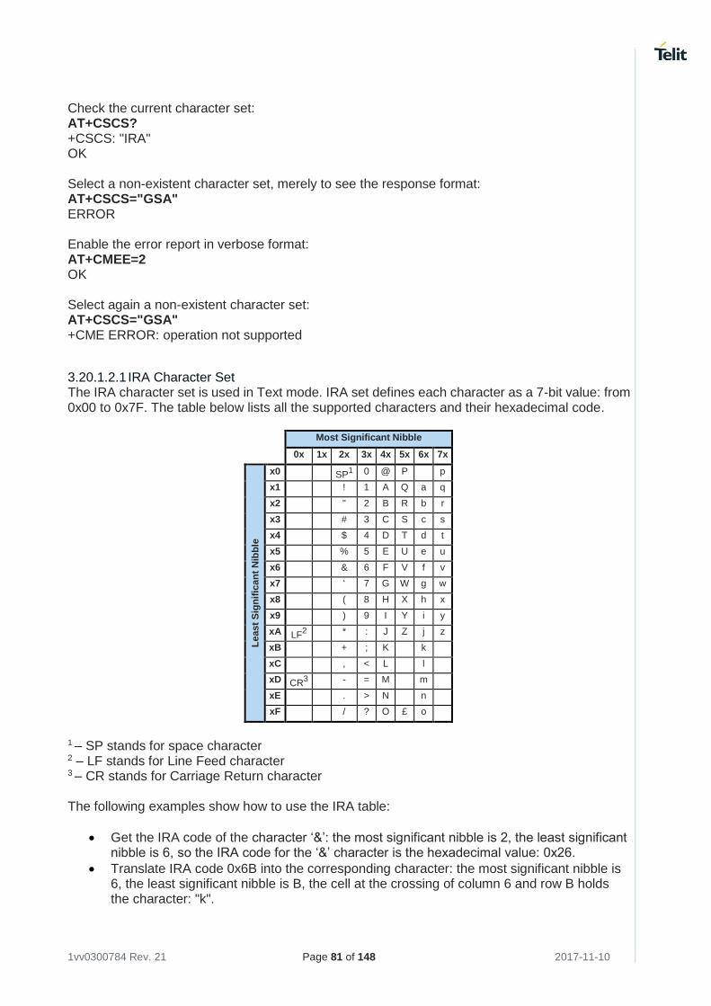
1vv0300784 Rev. 21 Page 81 of 148 2017-11-10
Check the current character set: AT+CSCS? +CSCS: "IRA" OK Select a non-existent character set, merely to see the response format: AT+CSCS="GSA" ERROR Enable the error report in verbose format: AT+CMEE=2 OK Select again a non-existent character set: AT+CSCS="GSA" +CME ERROR: operation not supported
3.20.1.2.1 IRA Character Set The IRA character set is used in Text mode. IRA set defines each character as a 7-bit value: from 0x00 to 0x7F. The table below lists all the supported characters and their hexadecimal code.
Most Significant Nibble
0x 1x 2x 3x 4x 5x 6x 7x
Le
ast
Sig
nif
ican
t N
ibb
le
x0 SP1 0 @ P p
x1 ! 1 A Q a q
x2 " 2 B R b r
x3 # 3 C S c s
x4 $ 4 D T d t
x5 % 5 E U e u
x6 & 6 F V f v
x7 ‘ 7 G W g w
x8 ( 8 H X h x
x9 ) 9 I Y i y
xA LF2 * : J Z j z
xB + ; K k
xC , < L l
xD CR3 - = M m
xE . > N n
xF / ? O £ o
1 – SP stands for space character 2 – LF stands for Line Feed character 3 – CR stands for Carriage Return character The following examples show how to use the IRA table:
• Get the IRA code of the character ‘&’: the most significant nibble is 2, the least significant nibble is 6, so the IRA code for the ‘&’ character is the hexadecimal value: 0x26.
• Translate IRA code 0x6B into the corresponding character: the most significant nibble is 6, the least significant nibble is B, the cell at the crossing of column 6 and row B holds the character: "k".
1vv0300784 Rev. 21 Page 82 of 148 2017-11-10
3.20.1.2.2 UCS2 Character Set The UCS2 Character Set is used in Text mode.
• Phone number 329 05 69 6... converted into "UCS2" format: 3=0033, 2=0032, 9=0039, 0=0030, 5=0035, 6=0036, 9=0039, 6=0036 ...
• Text HELLO converted into UCS2 format: H=0048, E=0045, L=004C, O=004F
3.20.2 Read SMSC Number
The module sends the SMS message to the SMSC Center, where the message is dispatched towards its destination or is kept until the delivery is possible. To ensure the correct operation of this service, the number of the SMSC Center must be configured on the module in accordance with the network operator used. To know the SMSC number stored on the module, use the following AT command. AT+CSCA? Check the stored SMSC number: AT+CSCA? +CSCA: "+39X20XX58XX0",145 OK SMSC number is compliant with the international numbering scheme.
3.20.3 Set SMSC Number
Use the following AT command to store a new SMSC number. The old number is overwritten. AT+CSCA=<number>,<type> Set up the desired SMSC number in international format: AT+CSCA=+39X20XX58XX0,145 OK This setting remains stored in the SIM card until it is changed or deleted, so this operation may be done only once if the SIM Card is not changed. Enter the command with no SMSC number: AT+CSCA=,145 OK Check the stored SMSC number: AT+CSCA? +CSCA: "+",145 OK Enable error report in verbose format: AT+CMEE=2 OK Enter the command with no parameters: AT+CSCA= ERROR
1vv0300784 Rev. 21 Page 83 of 148 2017-11-10
3.20.4 Send a SMS
Use the following AT command to send a SMS. To read and set the SMSC number see § 3.20.2 and 3.20.3 AT+CMGS
3.20.4.1 2G Modules
Example 1 Send a SMS to the module itself and do not store it. Use the UCS2 character set. Select Text Mode. AT+CMGF=1 OK Check the SMS operation mode provided by the module. AT#SMSMODE=? #SMSMODE: (0-2) OK Disable improved SMS operation mode. It is not suggested. AT#SMSMODE=0 OK Select the UCS2 character set. AT+CSCS="UCS2" OK Set SMS parameters: AT+CSMP=17,168,0,26 OK Select how the new received message event is notified by the DCE to the DTE. AT+CNMI=1,1,0,0,0 OK Send the message to the module itself. The UCS2 character set is used:
• Phone number 329 05 69 628 is converted into "UCS2" format: 3=0033, 2=0032, 9=0039, 0=0030, 5=0035, 6=0036, 9=0039, 6=0036, 2=0032, 8=0038
• Text CIAO is converted into UCS2 format: C=0043, I=0049, A=0041, O=004F AT+CMGS=0033003200390030003500360039003600320038 > 004300490041004F (close the message with Ctrl Z) +CMGS: 81 OK The module itself receives the SMS, the following unsolicited indication is shown on DTE: +CMTI: "SM",3 The SMS was successfully sent to the SMSC Center, and its network reference number is 81. Do not confuse message reference with message index position: the first one indicates the network reference for identifying the sent message, the second one – reported by the unsolicited
1vv0300784 Rev. 21 Page 84 of 148 2017-11-10
indication – indicates that the module receives the message and it is stored on the position 3 of the "SM" storage. Select the "SM" storage as indicated by the unsolicited indication. AT+CPMS="SM" +CPMS: 3,50,3,50,3,50 OK Read the message from the storage position indicated by the unsolicited indication. AT+CMGR=3 +CMGR: "REC UNREAD","002B003300390033003200390030003500360039003600320038", "00570049004E0044002000530049004D","08/05/13,12:22:08+08" 004300490041004F OK Example 2 Send a SMS to the module itself and do not store it. Select Text Mode AT+CMGF=1 OK Enable the improved SMS operation mode. It is suggested. AT#SMSMODE=1 OK Select how the new received message event is notified by the DCE to the DTE. AT+CNMI=1,1,0,0,0 OK Send the message to the module itself. AT+CMGS="+39329X569YYY" > SEND THE SMS #1 TO THE MODULE ITSELF (close the message with Ctrl Z) +CMGS: 76 OK The module itself receives the SMS #1, the following unsolicited indication is shown on DTE: +CMTI: "SM",1 The SMS was successfully sent to the SMSC Center, and its network reference number is 76. Use unsolicited indication parameter to read the SMS #1 for the first time. AT+CMGR=1 +CMGR: "REC UNREAD","+39329X569YYY","WIND SIM","08/04/18,13:58:04+08" SEND THE SMS #1 TO THE MODULE ITSELF OK
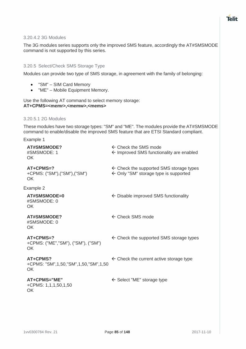
1vv0300784 Rev. 21 Page 85 of 148 2017-11-10
3.20.4.2 3G Modules
The 3G modules series supports only the improved SMS feature, accordingly the AT#SMSMODE command is not supported by this series.
3.20.5 Select/Check SMS Storage Type
Modules can provide two type of SMS storage, in agreement with the family of belonging:
• "SM" – SIM Card Memory
• "ME" – Mobile Equipment Memory. Use the following AT command to select memory storage: AT+CPMS=<memr>,<memw>,<mems>
3.20.5.1 2G Modules
These modules have two storage types: "SM" and "ME". The modules provide the AT#SMSMODE command to enable/disable the improved SMS feature that are ETSI Standard compliant.
Example 1
AT#SMSMODE? Check the SMS mode #SMSMODE: 1 Improved SMS functionality are enabled OK AT+CPMS=? Check the supported SMS storage types +CPMS: ("SM"),("SM"),("SM") Only "SM" storage type is supported OK
Example 2
AT#SMSMODE=0 Disable improved SMS functionality #SMSMODE: 0 OK AT#SMSMODE? Check SMS mode #SMSMODE: 0 OK AT+CPMS=? Check the supported SMS storage types +CPMS: ("ME","SM"), ("SM"), ("SM") OK AT+CPMS? Check the current active storage type +CPMS: "SM",1,50,"SM",1,50,"SM",1,50 OK AT+CPMS="ME" Select "ME" storage type +CPMS: 1,1,1,50,1,50 OK
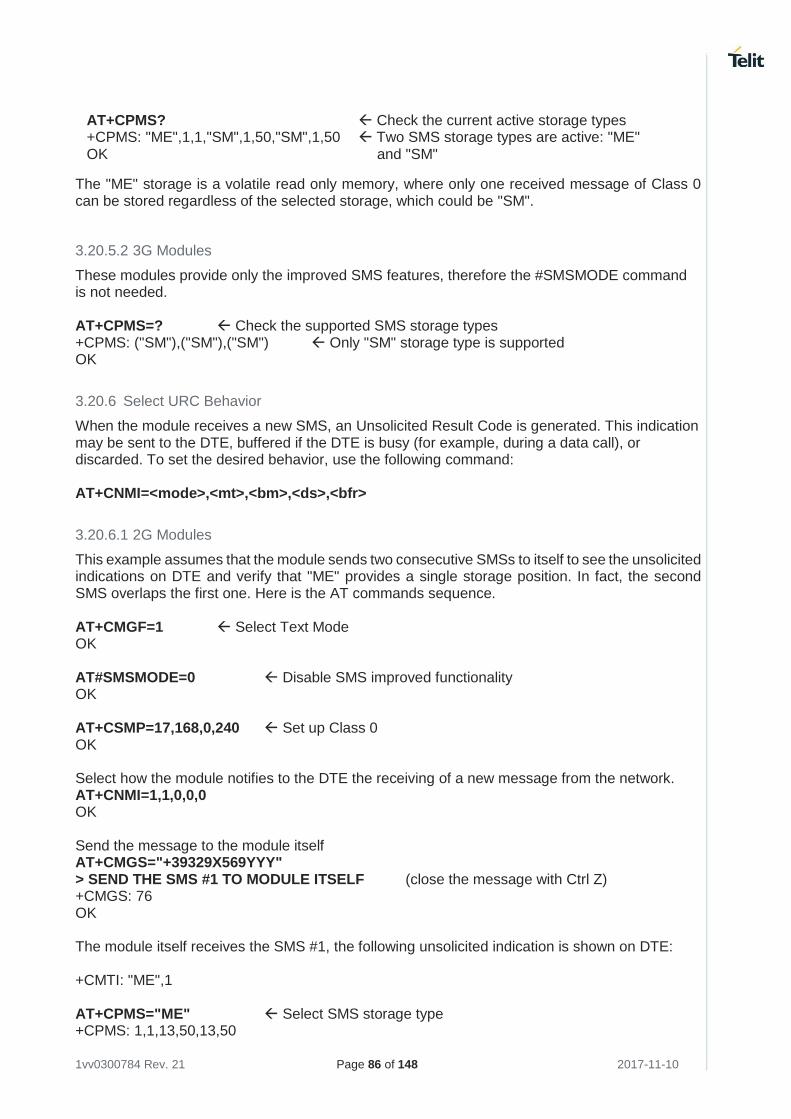
1vv0300784 Rev. 21 Page 86 of 148 2017-11-10
AT+CPMS? Check the current active storage types +CPMS: "ME",1,1,"SM",1,50,"SM",1,50 Two SMS storage types are active: "ME" OK and "SM"
The "ME" storage is a volatile read only memory, where only one received message of Class 0 can be stored regardless of the selected storage, which could be "SM".
3.20.5.2 3G Modules
These modules provide only the improved SMS features, therefore the #SMSMODE command is not needed. AT+CPMS=? Check the supported SMS storage types +CPMS: ("SM"),("SM"),("SM") Only "SM" storage type is supported OK
3.20.6 Select URC Behavior
When the module receives a new SMS, an Unsolicited Result Code is generated. This indication may be sent to the DTE, buffered if the DTE is busy (for example, during a data call), or discarded. To set the desired behavior, use the following command: AT+CNMI=<mode>,<mt>,<bm>,<ds>,<bfr>
3.20.6.1 2G Modules
This example assumes that the module sends two consecutive SMSs to itself to see the unsolicited indications on DTE and verify that "ME" provides a single storage position. In fact, the second SMS overlaps the first one. Here is the AT commands sequence. AT+CMGF=1 Select Text Mode OK AT#SMSMODE=0 Disable SMS improved functionality OK AT+CSMP=17,168,0,240 Set up Class 0 OK Select how the module notifies to the DTE the receiving of a new message from the network. AT+CNMI=1,1,0,0,0 OK Send the message to the module itself AT+CMGS="+39329X569YYY" > SEND THE SMS #1 TO MODULE ITSELF (close the message with Ctrl Z) +CMGS: 76 OK The module itself receives the SMS #1, the following unsolicited indication is shown on DTE: +CMTI: "ME",1 AT+CPMS="ME" Select SMS storage type +CPMS: 1,1,13,50,13,50
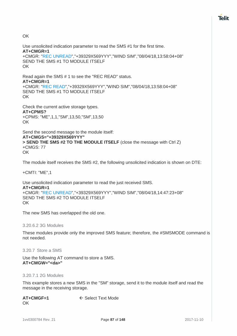
1vv0300784 Rev. 21 Page 87 of 148 2017-11-10
OK Use unsolicited indication parameter to read the SMS #1 for the first time. AT+CMGR=1 +CMGR: "REC UNREAD","+39329X569YYY","WIND SIM","08/04/18,13:58:04+08" SEND THE SMS #1 TO MODULE ITSELF OK Read again the SMS # 1 to see the "REC READ" status. AT+CMGR=1 +CMGR: "REC READ","+39329X569YYY","WIND SIM","08/04/18,13:58:04+08" SEND THE SMS #1 TO MODULE ITSELF OK Check the current active storage types. AT+CPMS? +CPMS: "ME",1,1,"SM",13,50,"SM",13,50 OK Send the second message to the module itself: AT+CMGS="+39329X569YYY" > SEND THE SMS #2 TO THE MODULE ITSELF (close the message with Ctrl Z) +CMGS: 77 OK The module itself receives the SMS #2, the following unsolicited indication is shown on DTE: +CMTI: "ME",1 Use unsolicited indication parameter to read the just received SMS. AT+CMGR=1 +CMGR: "REC UNREAD","+39329X569YYY","WIND SIM","08/04/18,14:47:23+08" SEND THE SMS #2 TO MODULE ITSELF OK The new SMS has overlapped the old one.
3.20.6.2 3G Modules
These modules provide only the improved SMS feature; therefore, the #SMSMODE command is not needed.
3.20.7 Store a SMS
Use the following AT command to store a SMS. AT+CMGW="<da>"
3.20.7.1 2G Modules
This example stores a new SMS in the "SM" storage, send it to the module itself and read the message in the receiving storage. AT+CMGF=1 Select Text Mode OK
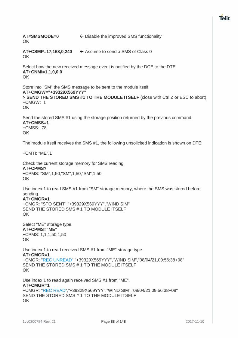
1vv0300784 Rev. 21 Page 88 of 148 2017-11-10
AT#SMSMODE=0 Disable the improved SMS functionality OK AT+CSMP=17,168,0,240 Assume to send a SMS of Class 0 OK Select how the new received message event is notified by the DCE to the DTE AT+CNMI=1,1,0,0,0 OK Store into "SM" the SMS message to be sent to the module itself. AT+CMGW="+39329X569YYY" > SEND THE STORED SMS #1 TO THE MODULE ITSELF (close with Ctrl Z or ESC to abort) +CMGW: 1 OK Send the stored SMS #1 using the storage position returned by the previous command. AT+CMSS=1 +CMSS: 78 OK The module itself receives the SMS #1, the following unsolicited indication is shown on DTE: +CMTI: "ME",1 Check the current storage memory for SMS reading. AT+CPMS? +CPMS: "SM",1,50,"SM",1,50,"SM",1,50 OK Use index 1 to read SMS #1 from "SM" storage memory, where the SMS was stored before sending. AT+CMGR=1 +CMGR: "STO SENT","+39329X569YYY","WIND SIM" SEND THE STORED SMS # 1 TO MODULE ITSELF OK Select "ME" storage type. AT+CPMS="ME" +CPMS: 1,1,1,50,1,50 OK Use index 1 to read received SMS #1 from "ME" storage type. AT+CMGR=1 +CMGR: "REC UNREAD","+39329X569YYY","WIND SIM","08/04/21,09:56:38+08" SEND THE STORED SMS # 1 TO THE MODULE ITSELF OK Use index 1 to read again received SMS #1 from "ME". AT+CMGR=1 +CMGR: "REC READ","+39329X569YYY","WIND SIM","08/04/21,09:56:38+08" SEND THE STORED SMS # 1 TO THE MODULE ITSELF OK
1vv0300784 Rev. 21 Page 89 of 148 2017-11-10
3.20.7.2 3G Modules
This example stores a SMS in the "SM" storage, send it to the module itself and read the message in the receiving storage. AT+CMGF=1 Select Text Mode OK AT+CSMP=17,168,0,240 Assume to send a SMS of Class 0 OK Select how the new received message event is notified by the DCE to the DTE AT+CNMI=1,1,0,0,0 OK Store into "SM" the SMS message to be sent to the module itself. AT+CMGW="+39329X569YYY" > SEND THE STORED SMS #1 TO THE MODULE ITSELF (close with Ctrl Z or ESC to abort) +CMGW: 5 OK Use index 5 to read SMS #1 from "SM" storage type. AT+CMGR=5 +CMGR: "STO SENT","+39329X569YYY","WIND SIM" SEND THE STORED SMS # 1 TO THE MODULE ITSELF OK Send the stored SMS #1using the storage position 5 returned by the previous command. AT+CMSS=5 +CMSS: 78 OK The module itself receives the SMS #1, the following unsolicited indication is shown on DTE: +CMTI: "SM",6 Check the current SMS storage type. AT+CPMS? +CPMS: "SM",6,30,"SM",6,30,"SM",6,30 OK Use index 6 to read received SMS #1 from "SM" storage memory. AT+CMGR=6 +CMGR: "REC UNREAD","+39329X569YYY","WIND SIM","08/04/21,09:56:38+08" SEND THE STORED SMS # 1 TO THE MODULE ITSELF OK Use index 6 to read again received SMS #1 from "SM" storage memory. AT+CMGR=6 +CMGR: "REC READ","+39329X569YYY","WIND SIM","08/04/21,09:56:38+08" SEND THE STORED SMS # 1 TO THE MODULE ITSELF OK
1vv0300784 Rev. 21 Page 90 of 148 2017-11-10
3.20.7.3 PDU Mode
+CMGW command does not work when the module is in PDU mode. Example AT+CMGF=0 Set up PDU Mode OK Store into "SM" storage the SMS message to be sent. AT+CMGW="+39329X569YYY" +CMS ERROR: 304 the command does not work when the module is in PDU Mode. Set up Text Mode. AT+CMGF=1 OK Store into "SM" storage the SMS message to be sent. AT+CMGW="+39329X569YYY" > EDIT NEW SMS … (use ESC to abort the command.) OK
3.20.8 Send a Stored SMS
A SMS stored in the "SM" storage type is sent using the following AT command. Its storage location index is needed.
AT+CMSS=<index>
If the module belongs to one of the 2G series, you must use AT#SMSMODE=1
Example Send the stored SMS to the module itself: Select Text Mode AT+CMGF=1 OK Select "SM" storage to read SMS AT+CPMS="SM" +CPMS: 1,50,1,50,1,50 OK Read the SMS stored on position 1. AT+CMGR=1 +CMGR: "STO SENT","+39329X569YYY","WIND SIM" SEND THE STORED SMS # 1 TO MODULE ITSELF OK Select how the new received message event is indicated by the DCE to the DTE. AT+CNMI=1,1,0,0,0 OK
1vv0300784 Rev. 21 Page 91 of 148 2017-11-10
Send the stored SMS # 1 message to module itself. AT+CMSS=1 +CMSS: 79 OK The module itself receives the SMS #1, the following unsolicited indication is shown on DTE: +CMTI: "SM",2
3.20.9 Send a New SMS using GPRS service
An SMS can be sent by means of the GPRS service [4]. It is worth to remind that not all Network Operators support this feature.
If the module belongs to one of the 2G series, you must use AT#SMSMODE=1.
Example Send the SMS message to the module itself, not store it before transmitting and use the GPRS service. AT#SELINT=2 Select AT command interface style OK AT+CGSMS=2 Select the GPRS service OK Check if the module is attached to GPRS service AT+CGATT? +CGATT: 1 OK Select Text Mode. AT+CMGF=1 OK Select how the new received message event is indicated by the DCE to the DTE. AT+CNMI=1,1,0,0,0 OK Send the message to the module itself. AT+CMGS="+386X18X19X4" > SEND THE SMS BY MEANS OF THE GPRS SERVICE TO ITSELF (close with Ctrl Z) +CMGS: 14 OK The module itself receives the SMS, the following unsolicited indication is shown on DTE: +CMTI: "SM",11 AT+CPMS="SM"
1vv0300784 Rev. 21 Page 92 of 148 2017-11-10
+CPMS: 11,50,11,50,11,50 OK Use unsolicited indication parameter to read the SMS for the first time. AT+CMGR=11 +CMGR: "REC UNREAD","+386X18X19X4","","09/08/03,14:14:04+08" SEND THE SMS BY MEANS OF THE GPRS SERVICE TO ITSELF OK
3.20.10 Delete an SMS
Use the following AT command to delete an SMS stored on the "SM" storage type. AT+CMGD=<index> Example Deleting an SMS stored in "SM" storage type: AT+CPMS="SM" Select memory storage +CPMS: 13,50,13,50,13,50 OK AT+CMGD=? Check the SMS +CMGD: (1,2,3,4,5,6,7,8,9,10,11,12,13),(0-4) OK Delete SMS in memory position 1. AT+CMGD=1 OK Check if the SMS is deleted: AT+CMGD=? +CMGD: (2,3,4,5,6,7,8,9,10,11,12,13),(0-4) OK Delete all SMS. Disregard the first parameter of the +CMGD. AT+CMGD=1,4 OK AT+CMGD=? +CMGD: (),(0-4) OK
3.20.10.1 2G Modules
AT#SMSMODE=0 OK AT+CPMS="ME" Select "ME" storage type +CPMS: 1,1,6,30,6,30 OK AT+CMGD=? Check the SMS. +CMGD: (1),(0-4) OK
1vv0300784 Rev. 21 Page 93 of 148 2017-11-10
AT+CMGD=1 Delete SMS in storage position 1 OK Check if the SMS is deleted. AT+CMGD=? +CMGD: (),(0-4) OK
3.20.11 Read an SMS
A SMS is read with the following command: AT+CMGR=<index> Example AT+CPMS? +CPMS: "SM",1,50,"SM",1,50,"SM",1,50 OK Read the SMS #1, for the first time, in storage memory "SM", position 1: AT+CMGR=1 +CMGR: "STO SENT","+39329X569YYY","WIND SIM" SEND THE STORED SMS # 1 TO MODULE ITSELT OK
3.20.12 SMS Status
SMSs can be gathered into 5 different groups depending on their Status:
• REC UNREAD: received messages still not read
• REC READ: received messages already read
• STO UNSENT: written messages not yet sent
• STO SENT: written messages already sent
• ALL: all types of messages Use the following AT command to query the SMS status: AT+CMGL=<stat> Check if Text Mode is active AT+CMGF? +CMGF: 1 Text Mode is active OK Check the supported SMS status AT+CMGL=? +CMGL: ("REC UNREAD","REC READ","STO UNSENT","STO SENT","ALL") OK Check the available SMS storage type AT+CPMS? +CPMS: "SM",6,30,"SM",6,30,"SM",6,30 OK List all the SMSs stored on "SM" storage with their Status. AT+CMGL="ALL"
1vv0300784 Rev. 21 Page 94 of 148 2017-11-10
+CMGL: 1,"REC READ", •••• SMS body •••• +CMGL: 2,"REC READ", •••• SMS body •••• +CMGL: 3,"REC READ", •••• SMS body •••• +CMGL: 4,"STO SENT", •••• SMS body •••• +CMGL: 5,"STO SENT", •••• SMS body •••• +CMGL: 6,"REC READ", •••• SMS body •••• OK List the SMSs stored on "SM" storage with their Status=STO SENT AT+CMGL="STO SENT" +CMGL: 4,"STO SENT", •••• SMS body •••• +CMGL: 5,"STO SENT", •••• SMS body •••• OK
3.20.12.1 2G Modules
AT#SMSMODE=0 OK Check the supported storage types AT+CPMS=? +CPMS:"ME","SM"),("SM"),("SM") OK Check if Text Mode is active. AT+CMGF? +CMGF: 1 OK Check the supported SMS status. AT+CMGL=? +CMGL: ("REC UNREAD","REC READ","STO UNSENT","STO SENT","ALL") OK Select "ME" storage type. AT+CPMS="ME" +CPMS: 1,1,1,50,1,50 OK List SMSs stored in the "ME" storage type. AT+CMGL="ALL" +CMGL: 1,"REC READ", •••• SMS body •••• OK AT+CMGL="REC UNREAD" OK
3.20.13 Cell Broadcast Service
GSM Standard specifies two different types of SMS:
• SMS Point to Point (SMS/PP),
• SMS Cell Broadcast (SMS/CB).
1vv0300784 Rev. 21 Page 95 of 148 2017-11-10
The first type can send a text message long up to 160 characters from a module to the another (as stated on the previous paragraphs), the second type allows the Network to send, at the same time, a message to all modules contained in the defined area including one or more radio cells. The availability and the implementation of the Cell Broadcast Service are strictly connected with the Network Operator of the subscriber. Use the following AT command to enable the Cell Broadcast Service: AT+CSCB=[<mode>[,<mids>[,<dcss>]]] Select Text Mode. AT+CMGF=1 OK Select the District service. AT+CSCB=0,50,0 OK Select how the new received message event is indicated by the DCE to the DTE. AT+CNMI=2,0,2,0,0 OK After a while the "District" broadcast message is displayed on the DTE. +CBM: 24,50,1,1,1 TRIESTE +CBM: 4120,50,2,1,1 TRIESTE +CBM: 8216,50,1,1,1 TRIESTE +CBM: 12312,50,2,1,1 TRIESTE The network operator can provide the following list of Services, it is not mandatory:
<mids> Service name
000 Index
010 Flashes
020 Hospitals
022 Doctors
024 Pharmacy
030 Long Distant Road Reports
032 Local Road Reports
034 Taxis
040 Weather
050 District
052 Network Information
054 Operator Services
056 Directory Inquiries (national)
057 Directory Inquiries (international)
058 Customer Care (national)
059 Customer Care (international)
3.20.14 Read concatenated SMS
Use the following AT command to read concatenated SMSs:
1vv0300784 Rev. 21 Page 96 of 148 2017-11-10
AT#CMGLCONCINDEX Example Check the number of stored SMSs AT+CPMS? +CPMS: "SM",6,30,"SM",6,30,"SM",6,30 OK 6 SMSs are stored. Check if concatenated SMSs are stored AT#CMGLCONCINDEX OK No concatenated SMSs are stored Set up Text Mode AT+CMGF=1 OK Set SMS parameters AT+CSMP=17,167,0,242 OK Store two concatenated SMSs (they are indicated with two colors): AT+CMGW= "+3932X056Y6X8" >123456789012345678901234567890123456789012345678901234567890123456789012345678901234567890123456789012345678901234567890123456789012345678901234567890123456789098765432109876543210 +CMGW: 8 OK Check the number of SMSs stored on the "SM" storage type AT+CPMS? +CPMS: "SM",8,30,"SM",8,30,"SM",8,30 OK Check the concatenated SMSs presence AT#CMGLCONCINDEX #CMGLCONCINDEX: 2,7,8 OK 2 SMSs are concatenated. Their storage positions are: 7, 8. Read the SMS with index=7. The following visualization is valid for HSPS-GSM/GPRS family and GSM/GPRS family (it must have: #SMSMODE=1). To get info concerning the used coding refer to [19]. AT+CMGR=7 +CMGR: "STO UNSENT","+3932X056Y6X8","" 0608040005020131D98C56B3DD7039584C36A3D56C375C0E1693CD6835DB0D9783C564335ACD76C3E56031D98C56B3DD7039584C36A3D56C375C0E1693CD6835DB0D9783C564335ACD76C3E56031D98C56B3DD7039584C36A3D56C375C0E1693CD6835DB0D9783C564335ACD76C3E56031D98C56B3DD7039584C36A3D56C375C0E1693CD6835DB0D9783C564 OK Read the SMS with index=8. To get info concerning the used coding refer to [19]. AT+CMGR=8 +CMGR: "STO UNSENT","+3932X056Y6X8","" 06080400050202335ACD76C3E56039DCCD56A3CD6431580E77B3D56833590C06 OK
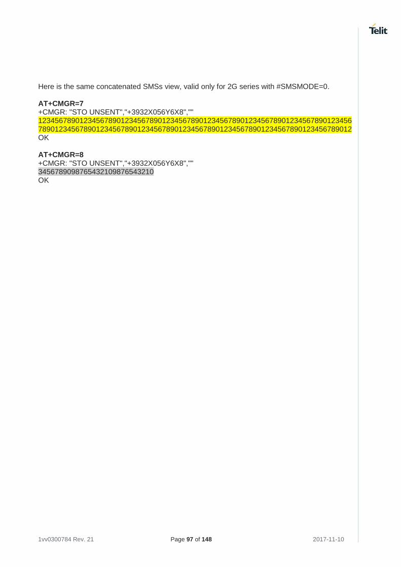
1vv0300784 Rev. 21 Page 97 of 148 2017-11-10
Here is the same concatenated SMSs view, valid only for 2G series with #SMSMODE=0. AT+CMGR=7 +CMGR: "STO UNSENT","+3932X056Y6X8","" 12345678901234567890123456789012345678901234567890123456789012345678901234567890123456789012345678901234567890123456789012345678901234567890123456789012 OK AT+CMGR=8 +CMGR: "STO UNSENT","+3932X056Y6X8","" 3456789098765432109876543210 OK
1vv0300784 Rev. 21 Page 98 of 148 2017-11-10
3.21 Phonebooks
The user can access the different Phonebook types, stored on the SIM card or on the NVM memory, by means of the dedicated AT commands. The modules support the Phonebooks described in the following sub-chapters. 3.21.1 Phonebook Storage
The choice of the Phonebook Storage must be the first Phonebook operation. Once storage is selected, it is no longer needed to select it again until the desired storage remains the same, and the module is not turned off. 3.21.1.1 2G Modules Use the following command to select the phonebook memory storage identified by <storage> parameter. To have more information on the command refer to document [1]. The command syntax is: AT+CPBS=<storage> Use the Test command to know the <storage> range provided by the module. AT+CPBS=? Example Read the supported range of Phonebook Storages. The <storage> range depends on the SIM, that must be inserted. AT+CPBS=? +CPBS: ("SM","FD","LD","MC","RC") OK Read the current phonebook storage AT+CPBS? +CPBS: "SM",8,250 OK Select "FD" phonebook storage AT+CPBS="FD" ERROR Enable error report in verbose format. AT+CMEE=2 OK Select "FD" phonebook storage AT+CPBS="FD" +CME ERROR: SIM PIN2 required Enter PIN2 AT+CPIN=PIN2 OK Select "FD" phonebook storage. AT+CPBS="FD"
1vv0300784 Rev. 21 Page 99 of 148 2017-11-10
OK
The following command can substitute the previous two commands: AT+CLCK="FD",1,PIN2 OK.
Select "MC" Phonebook Storage AT+CPBS="MC" OK AT+CPBS? +CPBS: "MC",0,20 OK
After module power on and PIN authentication, the module reads the data records stored on the SIM. During this activity, the phonebook access is inhibited for a time interval depending on various factors. If Phonebook commands are entered during this interval, the module returns an error message. In this case, retry the operations later.
3.21.1.2 3G/4G Modules Use the following command to select the phonebook memory storage identified by <storage> parameter. To have more information on the command refer to document [17], [26], and [27] according to the used module. The command syntax is: AT+CPBS=<storage>[,<password>] Use the Test command to know the <storage> range provided by the module. AT+CPBS=? Example Read the supported range of Phonebook Storages. The <storage> range depends on the SIM, that must be inserted. AT+CPBS=? +CPBS: ("SM","FD","LD","MC","RC","DC","ME","EN","ON","SD") OK Read the current phonebook storage AT+CPBS? +CPBS: "SM",8,250 OK
1vv0300784 Rev. 21 Page 100 of 148 2017-11-10
3.21.2 Search Phonebook Entries
Use the following AT command to search a Phonebook entry. AT+CPBF=<findtext> Examples Read the current Phonebook storage and select "SM" storage: AT+CPBS? +CPBS: "MC",0,20 OK AT+CPBS="SM" OK AT+CPBS? +CPBS: "SM",10,250 OK Look for entries having name starting with "FA" on the selected storage: AT+CPBF="FA" +CPBF: 7,"+39404192XYZ",145,"Fabio" +CPBF: 9,"0404X92XYX",129,"Fabrizio" OK Look for an entry not present on the selected storage. Before doing that verify the error report format. AT+CMEE? +CMEE: 2 OK AT+CPBF="FAUSTO" +CME ERROR: not found
The search for <name> string is not case sensitive and the string may or may not be included in double brackets.
3.21.3 Read Phonebook Entries
Use the following AT command to read a Phonebook entry: AT+CPBR=<index1>[,<index2>] Select "SM" storage: AT+CPBS="SM" OK Look for the entry at the position index = 7: AT+CPBR=7 +CPBR: 7,"+39404192XYZ",145,"Fabio" OK Look for the entries from position 7 up to position 9: AT+CPBR=7,9
1vv0300784 Rev. 21 Page 101 of 148 2017-11-10
+CPBR: 7,"+39404192XYZ",145,"Fabio" +CPBR: 9,"0404X92XYX",129,"Fabrizio" OK The position 8 is empty.
3.21.4 Write Phonebook Entry
Use the following AT command to write a Phonebook entry: AT+CPBW=[<index>][,<number>[,<type>[,<text>]]] Examples Select the "SM" phonebook: AT+CPBS="SM" OK Write a new record on the first free position of the selected "SM" phonebook: AT+CPBW=,"0404192XYY",129,"NewRecord" OK Check where the new record has been written: AT+CPBF="NEW" +CPBF: 8,"0404192XYY",129,"NewRecord" OK
3.21.5 Delete Phonebook Entry
Use the following AT command with only <index> parameter to delete a Phonebook entry: AT+CPBW=<index> Examples Select the "SM" phonebook: AT+CPBS="SM" OK Delete record 7 on the "SM" phonebook: AT+CPBW= 7 OK Try to delete a non-existent record on the "SM" phonebook, just to see the format response: AT+CPBF=99999999999 +CME ERROR: not found
The delete command overwrites the <index> record number with an empty record.
3.21.6 Dial Phonebook Entry
To dial a phone number stored in the Phonebook, the user must get the desired phone number index position using the +CPBF command. Once the <index> number is known, the user can establish the call.
1vv0300784 Rev. 21 Page 102 of 148 2017-11-10
ATD><n>[;] Wait for command response in accordance with the call type entered. Examples Establish a Voice call, on HS audio path, to "Fabio" whose number is stored on the SIM Phonebook: Select the "SM" as active storage. AT+CPBS="SM" OK Find the index number where "Fabio" is recorded. AT+CPBF="Fabio" +CPBF: 7,"+390404X9YYYY",145,"Fabio" OK Set up Voice Call. AT+FCLASS=8 OK Use software way to select HS audio path. AT#CAP=2 OK Set the volume. AT+CLVL=8 OK Check the mute setting. AT+CMUT? +CMUT: 0 Establish the voice call using the index. ATD>7 OK
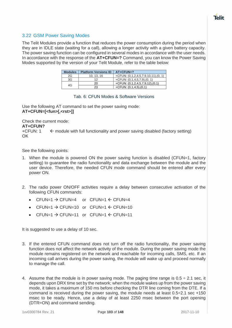
1vv0300784 Rev. 21 Page 103 of 148 2017-11-10
3.22 GSM Power Saving Modes
The Telit Modules provide a function that reduces the power consumption during the period when they are in IDLE state (waiting for a call), allowing a longer activity with a given battery capacity. The power saving function can be configured in several modes in accordance with the user needs. In accordance with the response of the AT+CFUN=? Command, you can know the Power Saving Modes supported by the version of your Telit Module, refer to the table below:
Modules Platform Versions ID AT+CFUN=?
2G 10, 13, 16 +CFUN: (0,1,2,4,5,7,9,10,11),(0, 1)
3G 12 +CFUN: (0,1,4,5,7,9),(0, 1)
4G 20 +CFUN: (0,1,2,4,5,7,9,12),(0,1)
23 +CFUN: (0,1,4,5),(0,1)
Tab. 6: CFUN Modes & Software Versions
Use the following AT command to set the power saving mode: AT+CFUN=[<fun>[,<rst>]] Check the current mode: AT+CFUN? +CFUN: 1 module with full functionality and power saving disabled (factory setting) OK
See the following points:
1. When the module is powered ON the power saving function is disabled (CFUN=1, factory setting) to guarantee the radio functionality and data exchange between the module and the user device. Therefore, the needed CFUN mode command should be entered after every power ON.
2. The radio power ON/OFF activities require a delay between consecutive activation of the following CFUN commands:
• CFUN=1 CFUN=4 or CFUN=1 CFUN=4
• CFUN=1 CFUN=10 or CFUN=1 CFUN=10
• CFUN=1 CFUN=11 or CFUN=1 CFUN=11
It is suggested to use a delay of 10 sec.
3. If the entered CFUN command does not turn off the radio functionality, the power saving function does not affect the network activity of the module. During the power saving mode the module remains registered on the network and reachable for incoming calls, SMS, etc. If an incoming call arrives during the power saving, the module will wake up and proceed normally to manage the call.
4. Assume that the module is in power saving mode. The paging time range is 0.5 ÷ 2.1 sec, it depends upon DRX time set by the network; when the module wakes up from the power saving mode, it takes a maximum of 150 ms before checking the DTR line coming from the DTE. If a command is received during the power saving, the module needs at least 0.5÷2.1 sec +150 msec to be ready. Hence, use a delay of at least 2250 msec between the port opening (DTR=ON) and command sending.
1vv0300784 Rev. 21 Page 104 of 148 2017-11-10
5. The CFUN mode can be saved into the selected profile only if the AT+CFUN command is entered the module through the AT0 parser (Instance #1, refer to documents [10], [22]).
3.22.1 CFUN=0 and 3G Modules
For HE910 series the behavior of the CFUN=0 is conditioned by the setting of the AT#ENS command, refer to § 3.11.8.3, and 3.11.8.4.
• AT#ENS=0 CFUN=0 has the standard functionality
• AT#ENS=1 CFUN=0 has the same functionality of CFUN=4
3.22.2 CFUNs and the Main Serial Port
This chapter describes the relation between the CFUN modes and the control lines (RTS, CTS refer to § 3.1) of the Main Serial Port (hereafter called AT interface). The § 3.22.3 describes the wake-up events (for example, unsolicited result code) that force the module to exit from the power saving mode temporarily or permanently.
CFUN=2, CFUN=4
These CFUN modes do not interact with the control serial lines of the AT interface.
Type in CFUN=2, the module disables Tx.
Type in CFUN=4, the module performs network deregistration, and SIM deactivation.
CFUN=0, CFUN=9
Here is the starting control lines configuration, the AT interface is working.
<DSR=ON>, RI=OFF, DCD=OFF, <CTS=ON>, RTS=ON (or OFF), DTR=ON
Type in CFUN=0 or CFUN=9. The module enters the NON-CYCLIC SLEEP mode, and the AT interface is no longer accessible. Here is the new control lines configuration. <DSR=OFF>, RI=OFF, DCD=OFF, <CTS=OFF>, RTS=ON (or OFF), DTR=ON.
Power saving mode is identified by <DSR=OFF>, <CTS=OFF>. Do not send further characters, they remain in the input buffer and may delay the output of an unsolicited result code.
• The RTS line toggling forces the module to exit power saving and enter CFUN=1 mode. The AT interface is again accessible.
The power saving mode (0 or 9) does not affect the radio activities of the module. It remains registered on the network and reachable for incoming calls or SMS. If a call incomes during the power saving mode, the module will wake up, enters CFUN=1 mode, and proceeds normally with the unsolicited incoming call code.
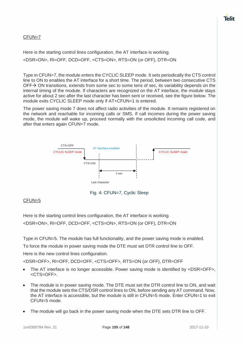
1vv0300784 Rev. 21 Page 105 of 148 2017-11-10
CFUN=7
Here is the starting control lines configuration, the AT interface is working.
<DSR=ON>, RI=OFF, DCD=OFF, <CTS=ON>, RTS=ON (or OFF), DTR=ON
Type in CFUN=7, the module enters the CYCLIC SLEEP mode. It sets periodically the CTS control line to ON to enables the AT interface for a short time. The period, between two consecutive CTS OFF ON transitions, extends from some sec to some tens of sec, its variability depends on the internal timing of the module. If characters are recognized on the AT interface, the module stays active for about 2 sec after the last character has been sent or received, see the figure below. The module exits CYCLIC SLEEP mode only if AT+CFUN=1 is entered.
The power saving mode 7 does not affect radio activities of the module. It remains registered on the network and reachable for incoming calls or SMS. If call incomes during the power saving mode, the module will wake up, proceed normally with the unsolicited incoming call code, and after that enters again CFUN=7 mode.
Fig. 4: CFUN=7, Cyclic Sleep
CFUN=5
Here is the starting control lines configuration, the AT interface is working.
<DSR=ON>, RI=OFF, DCD=OFF, <CTS=ON>, RTS=ON (or OFF), DTR=ON
Type in CFUN=5. The module has full functionality, and the power saving mode is enabled.
To force the module in power saving mode the DTE must set DTR control line to OFF.
Here is the new control lines configuration.
<DSR=OFF>, RI=OFF, DCD=OFF, <CTS=OFF>, RTS=ON (or OFF), DTR=OFF
• The AT interface is no longer accessible. Power saving mode is identified by <DSR=OFF>, <CTS=OFF>.
• The module is in power saving mode. The DTE must set the DTR control line to ON, and wait that the module sets the CTS/DSR control lines to ON, before sending any AT command. Now, the AT interface is accessible, but the module is still in CFUN=5 mode. Enter CFUN=1 to exit CFUN=5 mode.
• The module will go back in the power saving mode when the DTE sets DTR line to OFF.
CTS=OFF
CTS=ON
Last character
2 sec
CYCLIC SLEEP mode CYCLIC SLEEP mode
AT Interface enabled
1vv0300784 Rev. 21 Page 106 of 148 2017-11-10
The power saving mode 5 does not affect the radio functionalities of the module. It remains registered on the network and reachable for incoming calls or SMS. If call incomes during the power saving mode, the module will wake up, proceed normally with the unsolicited incoming call code, and after that enters again CFUN=5 mode, it is a CYCLIC SLEEP mode.
CFUN=10
Here is the starting control lines configuration, the AT interface is working.
<DSR=ON>, RI=OFF, DCD=OFF, <CTS=ON>, RTS=ON (or OFF), DTR=ON
Enter CFUN=10. The module is detached from the network (TX and RX are disabled), the SIM is deactivated, and the power saving mode is enabled.
• To force the module in power saving mode the DTE must set DTR control line to OFF. Here is the new control lines configuration. <DSR=OFF>, RI=OFF, DCD=OFF, <CTS=OFF>, RTS=ON (or OFF), DTR=OFF
• The AT interface is no longer accessible. Power saving mode is identified by <DSR=OFF>, <CTS=OFF>.
• The module is in power saving mode. The DTE must set the DTR control line to ON, and wait that the module sets the CTS/DSR control lines to ON, before sending any AT command. Now, the AT interface is accessible, but the module is still in CFUN=10 mode. Enter CFUN=1 to exit CFUN=10 mode.
• The module will go back in the power saving mode when the DTE sets DTR line to OFF.
CFUN=11
Here is the starting control lines configuration, the AT interface is working.
<DSR=ON>, RI=OFF, DCD=OFF, <CTS=ON>, RTS=ON (or OFF), DTR=ON
Enter CFUN=11. The module is detached from the network (TX and RX are disabled), the SIM is deactivated, and the power saving mode is automatically entered. Here is the new control lines configuration.
<DSR=OFF>, RI=OFF, DCD=OFF, <CTS=OFF>, RTS=ON (or OFF), DTR=ON
The AT interface is no longer accessible. Power saving mode is identified by <DSR=OFF>, <CTS=OFF>
• The module is in power saving. It monitors the RTS toggling every N seconds to change the current AT interface state (accessible/not accessible). The range of N extends from some sec to some tens of sec, its variability depends on the internal timing of the module. In any case, the CFUN=11 mode is still active.
1vv0300784 Rev. 21 Page 107 of 148 2017-11-10
• When the AT interface is accessible, enter CFUN=1 to exit CFUN=11mode.
3.22.3 CFUNs and Wake up Events
Before reading the Tab. 7, it is suggested to read § 3.22.2. See CFUN examples in § 3.22.4.
The Tab. 7 shown in the next page summarizes the behavior of the CFUN modes in relation with specific wake up event. The shaded row lists the available CFUN modes; the shaded Wake up Events column lists the possible events. Therefore, the cell on the crossing between the selected CFUN mode column and the row of the selected wake up event shows the new CFUN mode entered by the module after the occurrence of the wake-up event. It is assumed that the wake-up events occur when the module is in power saving mode.
The "N/A" abbreviation indicates that the specific wake up event shown in the table is not applicable to the selected CFUN. For example, incoming voice call is not applicable when the module is in CFUN=4 mode because the radio is turned off.
"The new mode depends on URC" means that the final CFUN mode of the module depends on the type of the URC. For example, if the wake-up event is the extraction of the SIM, #QSS URC is not generated if the module is in CFUN=4 mode because the SIM is deactivated, see § 3.22.4.1.
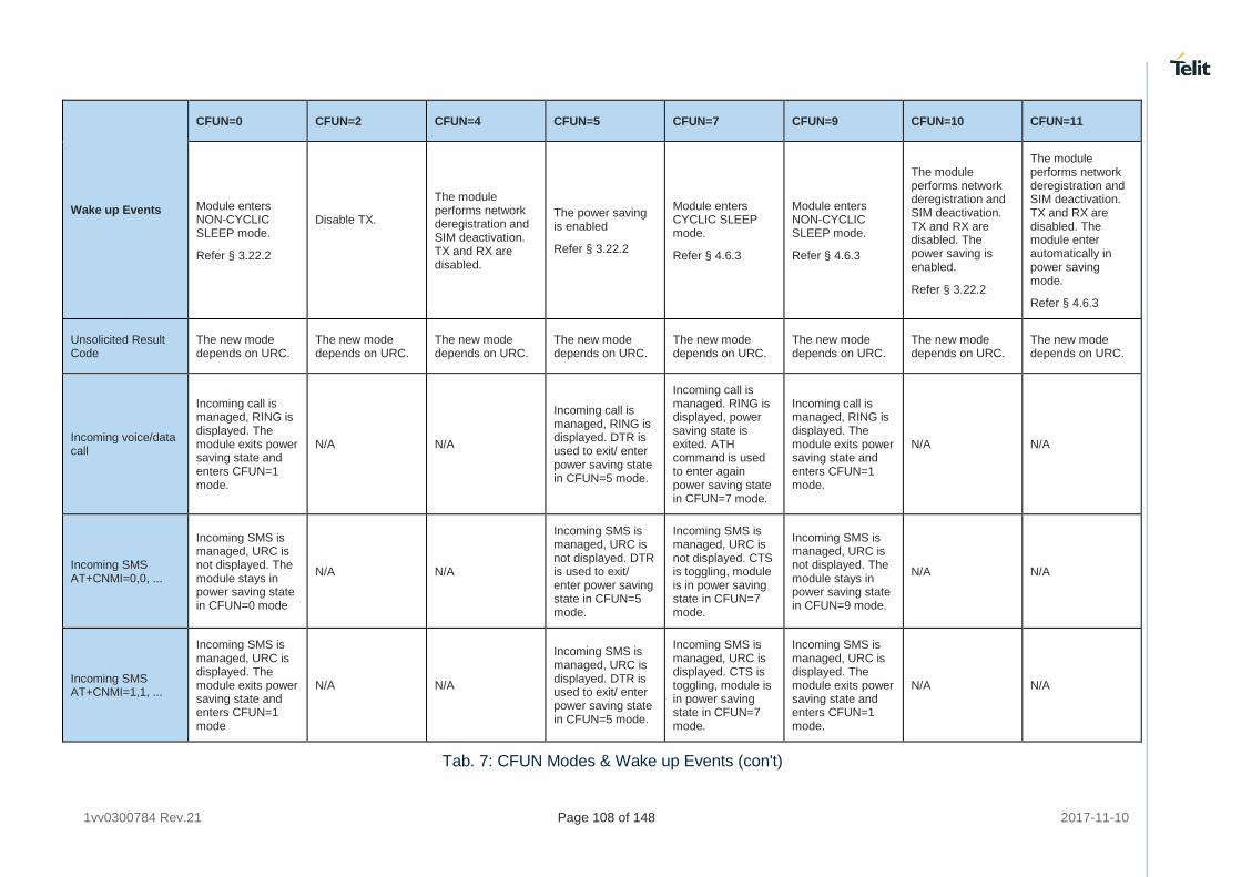
1vv0300784 Rev.21 Page 108 of 148 2017-11-10
Wake up Events
CFUN=0 CFUN=2 CFUN=4 CFUN=5 CFUN=7 CFUN=9 CFUN=10 CFUN=11
Module enters NON-CYCLIC SLEEP mode.
Refer § 3.22.2
Disable TX.
The module performs network deregistration and SIM deactivation. TX and RX are disabled.
The power saving is enabled
Refer § 3.22.2
Module enters CYCLIC SLEEP mode.
Refer § 4.6.3
Module enters NON-CYCLIC SLEEP mode.
Refer § 4.6.3
The module performs network deregistration and SIM deactivation. TX and RX are disabled. The power saving is enabled.
Refer § 3.22.2
The module performs network deregistration and SIM deactivation. TX and RX are disabled. The module enter automatically in power saving mode.
Refer § 4.6.3
Unsolicited Result Code
The new mode depends on URC.
The new mode depends on URC.
The new mode depends on URC.
The new mode depends on URC.
The new mode depends on URC.
The new mode depends on URC.
The new mode depends on URC.
The new mode depends on URC.
Incoming voice/data call
Incoming call is managed, RING is displayed. The module exits power saving state and enters CFUN=1 mode.
N/A N/A
Incoming call is managed, RING is displayed. DTR is used to exit/ enter power saving state in CFUN=5 mode.
Incoming call is managed. RING is displayed, power saving state is exited. ATH command is used to enter again power saving state in CFUN=7 mode.
Incoming call is managed, RING is displayed. The module exits power saving state and enters CFUN=1 mode.
N/A N/A
Incoming SMS AT+CNMI=0,0, ...
Incoming SMS is managed, URC is not displayed. The module stays in power saving state in CFUN=0 mode
N/A N/A
Incoming SMS is managed, URC is not displayed. DTR is used to exit/ enter power saving state in CFUN=5 mode.
Incoming SMS is managed, URC is not displayed. CTS is toggling, module is in power saving state in CFUN=7 mode.
Incoming SMS is managed, URC is not displayed. The module stays in power saving state in CFUN=9 mode.
N/A N/A
Incoming SMS AT+CNMI=1,1, ...
Incoming SMS is managed, URC is displayed. The module exits power saving state and enters CFUN=1 mode
N/A N/A
Incoming SMS is managed, URC is displayed. DTR is used to exit/ enter power saving state in CFUN=5 mode.
Incoming SMS is managed, URC is displayed. CTS is toggling, module is in power saving state in CFUN=7 mode.
Incoming SMS is managed, URC is displayed. The module exits power saving state and enters CFUN=1 mode.
N/A N/A
Tab. 7: CFUN Modes & Wake up Events (con't)
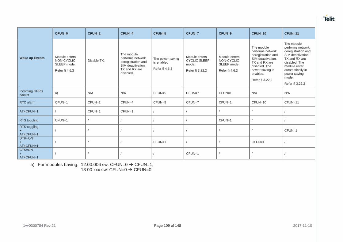
1vv0300784 Rev.21 Page 109 of 148 2017-11-10
Wake up Events
CFUN=0 CFUN=2 CFUN=4 CFUN=5 CFUN=7 CFUN=9 CFUN=10 CFUN=11
Module enters NON-CYCLIC SLEEP mode.
Refer § 4.6.3
Disable TX.
The module performs network deregistration and SIM deactivation. TX and RX are disabled.
The power saving is enabled
Refer § 4.6.3
Module enters CYCLIC SLEEP mode.
Refer § 3.22.2
Module enters NON-CYCLIC SLEEP mode.
Refer § 4.6.3
The module performs network deregistration and SIM deactivation. TX and RX are disabled. The power saving is enabled.
Refer § 3.22.2
The module performs network deregistration and SIM deactivation. TX and RX are disabled. The module enter automatically in power saving mode.
Refer § 3.22.2
Incoming GPRS packet
a) N/A N/A CFUN=5 CFUN=7 CFUN=1 N/A N/A
RTC alarm CFUN=1 CFUN=2 CFUN=4 CFUN=5 CFUN=7 CFUN=1 CFUN=10 CFUN=11
AT+CFUN=1 / CFUN=1 CFUN=1 / / / / /
RTS toggling CFUN=1 / / / / CFUN=1 / /
RTS toggling + AT+CFUN=1
/ / / / / / / CFUN=1
DTR=ON + AT+CFUN=1
/ / / CFUN=1 / / CFUN=1 /
CTS=ON + AT+CFUN=1
/ / / / CFUN=1 / / /
a) For modules having: 12.00.006 sw: CFUN=0 CFUN=1; 13.00.xxx sw: CFUN=0 CFUN=0.
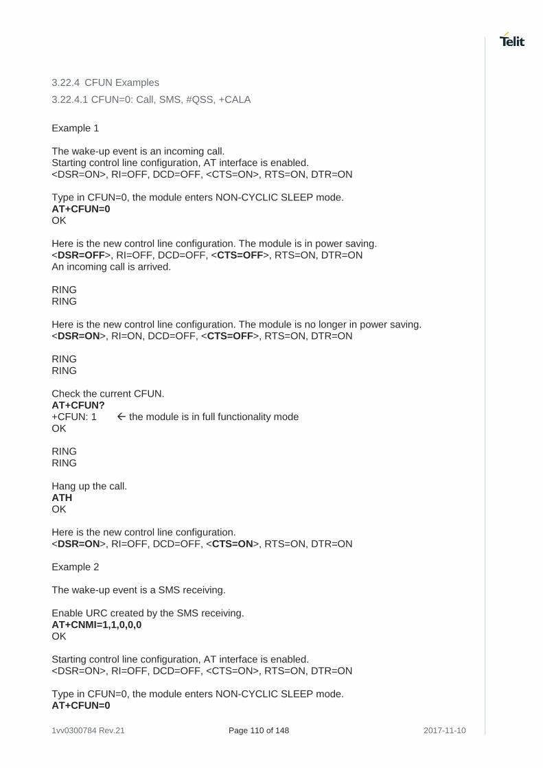
1vv0300784 Rev.21 Page 110 of 148 2017-11-10
3.22.4 CFUN Examples
3.22.4.1 CFUN=0: Call, SMS, #QSS, +CALA
Example 1 The wake-up event is an incoming call. Starting control line configuration, AT interface is enabled. <DSR=ON>, RI=OFF, DCD=OFF, <CTS=ON>, RTS=ON, DTR=ON Type in CFUN=0, the module enters NON-CYCLIC SLEEP mode. AT+CFUN=0 OK Here is the new control line configuration. The module is in power saving. <DSR=OFF>, RI=OFF, DCD=OFF, <CTS=OFF>, RTS=ON, DTR=ON An incoming call is arrived. RING RING Here is the new control line configuration. The module is no longer in power saving. <DSR=ON>, RI=ON, DCD=OFF, <CTS=OFF>, RTS=ON, DTR=ON RING RING Check the current CFUN. AT+CFUN? +CFUN: 1 the module is in full functionality mode OK RING RING Hang up the call. ATH OK Here is the new control line configuration. <DSR=ON>, RI=OFF, DCD=OFF, <CTS=ON>, RTS=ON, DTR=ON Example 2 The wake-up event is a SMS receiving. Enable URC created by the SMS receiving. AT+CNMI=1,1,0,0,0 OK Starting control line configuration, AT interface is enabled. <DSR=ON>, RI=OFF, DCD=OFF, <CTS=ON>, RTS=ON, DTR=ON Type in CFUN=0, the module enters NON-CYCLIC SLEEP mode. AT+CFUN=0
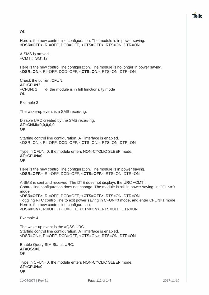
1vv0300784 Rev.21 Page 111 of 148 2017-11-10
OK Here is the new control line configuration. The module is in power saving. <DSR=OFF>, RI=OFF, DCD=OFF, <CTS=OFF>, RTS=ON, DTR=ON A SMS is arrived. +CMTI: "SM",17 Here is the new control line configuration. The module is no longer in power saving. <DSR=ON>, RI=OFF, DCD=OFF, <CTS=ON>, RTS=ON, DTR=ON Check the current CFUN. AT+CFUN? +CFUN: 1 the module is in full functionality mode OK Example 3 The wake-up event is a SMS receiving. Disable URC created by the SMS receiving. AT+CNMI=0,0,0,0,0 OK Starting control line configuration, AT interface is enabled. <DSR=ON>, RI=OFF, DCD=OFF, <CTS=ON>, RTS=ON, DTR=ON Type in CFUN=0, the module enters NON-CYCLIC SLEEP mode. AT+CFUN=0 OK Here is the new control line configuration. The module is in power saving. <DSR=OFF>, RI=OFF, DCD=OFF, <CTS=OFF>, RTS=ON, DTR=ON A SMS is sent and received. The DTE does not displays the URC +CMTI. Control line configuration does not change. The module is still in power saving, in CFUN=0 mode. <DSR=OFF>, RI=OFF, DCD=OFF, <CTS=OFF>, RTS=ON, DTR=ON Toggling RTC control line to exit power saving in CFUN=0 mode, and enter CFUN=1 mode. Here is the new control line configuration. <DSR=ON>, RI=OFF, DCD=OFF, <CTS=ON>, RTS=OFF, DTR=ON Example 4 The wake-up event is the #QSS URC. Starting control line configuration, AT interface is enabled. <DSR=ON>, RI=OFF, DCD=OFF, <CTS=ON>, RTS=ON, DTR=ON Enable Query SIM Status URC. AT#QSS=1 OK Type in CFUN=0, the module enters NON-CYCLIC SLEEP mode. AT+CFUN=0 OK
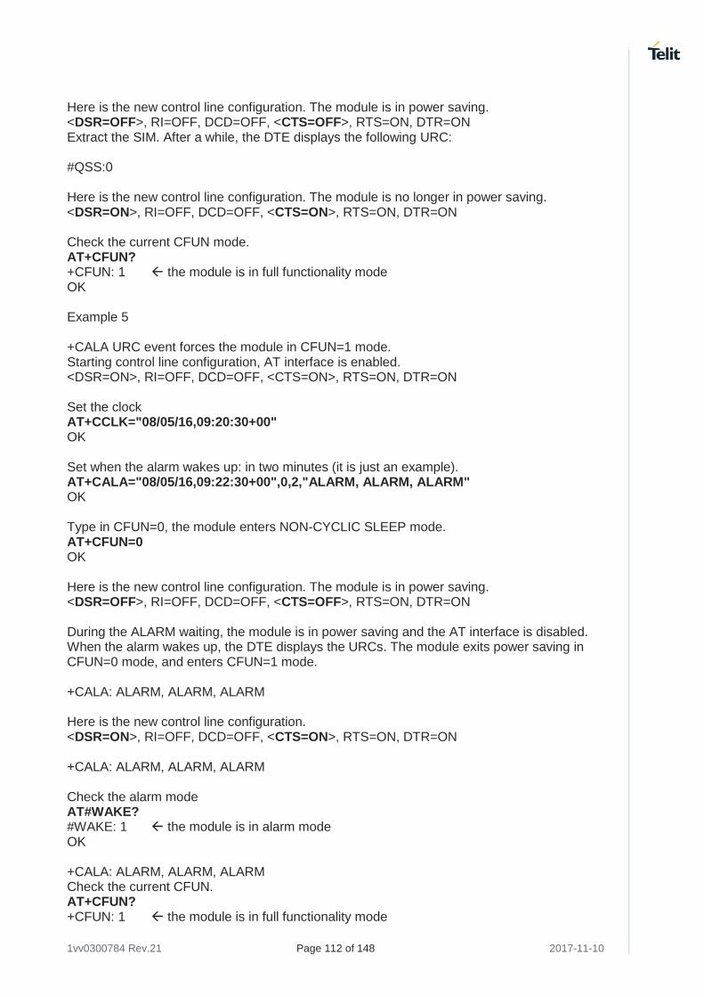
1vv0300784 Rev.21 Page 112 of 148 2017-11-10
Here is the new control line configuration. The module is in power saving. <DSR=OFF>, RI=OFF, DCD=OFF, <CTS=OFF>, RTS=ON, DTR=ON Extract the SIM. After a while, the DTE displays the following URC: #QSS:0 Here is the new control line configuration. The module is no longer in power saving. <DSR=ON>, RI=OFF, DCD=OFF, <CTS=ON>, RTS=ON, DTR=ON Check the current CFUN mode. AT+CFUN? +CFUN: 1 the module is in full functionality mode OK Example 5 +CALA URC event forces the module in CFUN=1 mode. Starting control line configuration, AT interface is enabled. <DSR=ON>, RI=OFF, DCD=OFF, <CTS=ON>, RTS=ON, DTR=ON Set the clock AT+CCLK="08/05/16,09:20:30+00" OK Set when the alarm wakes up: in two minutes (it is just an example). AT+CALA="08/05/16,09:22:30+00",0,2,"ALARM, ALARM, ALARM" OK Type in CFUN=0, the module enters NON-CYCLIC SLEEP mode. AT+CFUN=0 OK Here is the new control line configuration. The module is in power saving. <DSR=OFF>, RI=OFF, DCD=OFF, <CTS=OFF>, RTS=ON, DTR=ON During the ALARM waiting, the module is in power saving and the AT interface is disabled. When the alarm wakes up, the DTE displays the URCs. The module exits power saving in CFUN=0 mode, and enters CFUN=1 mode. +CALA: ALARM, ALARM, ALARM Here is the new control line configuration. <DSR=ON>, RI=OFF, DCD=OFF, <CTS=ON>, RTS=ON, DTR=ON +CALA: ALARM, ALARM, ALARM Check the alarm mode AT#WAKE? #WAKE: 1 the module is in alarm mode OK +CALA: ALARM, ALARM, ALARM Check the current CFUN. AT+CFUN? +CFUN: 1 the module is in full functionality mode
1vv0300784 Rev.21 Page 113 of 148 2017-11-10
OK +CALA: ALARM, ALARM, ALARM +CALA: ALARM, ALARM, ALARM After 90 sec, the module exits alarm mode. Check the alarm mode. AT#WAKE? #WAKE: 0 the module exited alarm mode OK
3.22.4.2 CFUN=2: #QSS, +CALA
Example 1 #QSS URC event leaves the module in CFUN=2 mode. Starting control line configuration, AT interface is enabled. <DSR=ON>, RI=OFF, DCD=OFF, <CTS=ON>, RTS=ON, DTR=ON Type in CFUN=2, the module disable Tx. AT+CFUN=2 OK Control line configuration is not changed. <DSR=ON>, RI=OFF, DCD=OFF, <CTS=ON>, RTS=ON, DTR=ON Enable Query SIM Status URC. AT#QSS=1 OK Extract the SIM. After a while, the DTE displays the following URC: #QSS:0 Control line configuration is not changed. <DSR=ON>, RI=OFF, DCD=OFF, <CTS=ON>, RTS=ON, DTR=ON Check the current CFUN mode. AT+CFUN? +CFUN: 2 the CFUN mode is not changed. OK Example 2 +CALA URC event leaves the module in CFUN=2 mode. Starting control line configuration, AT interface is enabled. <DSR=ON>, RI=OFF, DCD=OFF, <CTS=ON>, RTS=ON, DTR=ON Set the clock AT+CCLK="08/05/16,09:20:30+00" OK Set when the alarm wakes up: in two minutes (it is just an example).

1vv0300784 Rev.21 Page 114 of 148 2017-11-10
AT+CALA="08/05/16,09:22:30+00",0,2,"ALARM, ALARM, ALARM" OK Type in CFUN=2, the module disable Tx. AT+CFUN=2 OK Control line configuration is not changed <DSR=ON>, RI=OFF, DCD=OFF, <CTS=ON>, RTS=ON, DTR=ON When the alarm wakes up, the DTE displays the URCs. +CALA: ALARM, ALARM, ALARM Control line configuration is not changed. <DSR=ON>, RI=OFF, DCD=OFF, <CTS=ON>, RTS=ON, DTR=ON +CALA: ALARM, ALARM, ALARM Check the alarm mode AT#WAKE? #WAKE: 1 the module is in alarm mode OK +CALA: ALARM, ALARM, ALARM The module does not change CFUN mode. AT+CFUN? +CFUN: 2 OK +CALA: ALARM, ALARM, ALARM After 90 sec, the module exits alarm mode. Check the alarm mode. AT#WAKE? #WAKE: 0 the module exited alarm mode OK The module does not change CFUN mode. AT+CFUN? +CFUN: 2 OK
3.22.4.3 CFUN=4: #QSS, +CALA
Example 1 #QSS URC event leaves the module in CFUN=4 mode. Starting control line configuration, AT interface is enabled. <DSR=ON>, RI=OFF, DCD=OFF, <CTS=ON>, RTS=ON, DTR=ON Type in CFUN=4, the module performs network deregistration, and SIM deactivation. AT+CFUN=4
1vv0300784 Rev.21 Page 115 of 148 2017-11-10
OK Control line configuration is not changed. <DSR=ON>, RI=OFF, DCD=OFF, <CTS=ON>, RTS=ON, DTR=ON Enable Query SIM Status URC. AT#QSS=1 OK Extract the SIM. The URC does not arrive because CFUN=4 mode deactivates the SIM. The module stays in CFUN=4 mode. AT+CFUN? +CFUN: 4 OK Example 2 +CALA URC event leaves the module in CFUN=4 mode. Starting control line configuration, AT interface is enabled. <DSR=ON>, RI=OFF, DCD=OFF, <CTS=ON>, RTS=ON, DTR=ON Set the clock AT+CCLK="08/05/16,09:20:30+00" OK Set when the alarm wakes up: in two minutes (it is just an example). AT+CALA="08/05/16,09:22:30+00",0,2,"ALARM, ALARM, ALARM" OK Type in CFUN=4, the module performs network deregistration, and SIM deactivation. AT+CFUN=4 OK Control line configuration is not changed <DSR=ON>, RI=OFF, DCD=OFF, <CTS=ON>, RTS=ON, DTR=ON When the alarm wakes up, the DTE displays the URCs. +CALA: ALARM, ALARM, ALARM Control line configuration is not changed. <DSR=ON>, RI=OFF, DCD=OFF, <CTS=ON>, RTS=ON, DTR=ON +CALA: ALARM, ALARM, ALARM Check the alarm mode AT#WAKE? #WAKE: 1 the module is in alarm mode OK +CALA: ALARM, ALARM, ALARM The module does not change CFUN mode. AT+CFUN? +CFUN: 4
1vv0300784 Rev.21 Page 116 of 148 2017-11-10
OK +CALA: ALARM, ALARM, ALARM After 90 sec, the module exits alarm mode. Check the alarm mode. AT#WAKE? #WAKE: 0 the module exited alarm mode OK The module does not change CFUN mode. AT+CFUN? +CFUN: 4 OK
3.22.4.4 CFUN=5: Call, SMS, +CALA
Example 1 The wake-up event is an incoming call. Starting control line configuration, AT interface is enabled. <DSR=ON>, RI=OFF, DCD=OFF, <CTS=ON>, RTS=ON, DTR=ON Force the module in CFUN=5 mode, the power saving is enabled. AT+CFUN=5 OK Control line configuration does not change, AT interface is still enabled. <DSR=ON>, RI=OFF, DCD=OFF, <CTS=ON>, RTS=ON, DTR=ON Force the module in power saving. DTR OFF The module is in power saving, and the AT interface is disabled. <DSR=OFF>, RI=OFF, DCD=OFF, <CTS=OFF>, RTS=ON, DTR=OFF An incoming call is arrived RING RING Here is the new control line configuration: RING=ON <DSR=OFF>, RI=ON, DCD=OFF, <CTS=OFF>, RTS=ON, DTR=OFF RING RING Exit power saving, and enable again the hardware flow control of the serial port. DTRON <DSR=ON>, RI=ON, DCD=OFF, <CTS=ON>, RTS=ON, DTR=ON The module exits power saving, but stays in CFUN=5 mode. AT+CFUN? +CFUN:5 OK
1vv0300784 Rev.21 Page 117 of 148 2017-11-10
RING RING Hang up the call. ATH OK Enter power saving. DTR OFF The module enters again the power saving mode, and the AT interface is disabled. <DSR=OFF>, RI=OFF, DCD=OFF, <CTS=OFF>, RTS=ON, DTR=OFF Example 2 The wake-up event is a SMS receiving. Enable URC created by the SMS receiving. AT+CNMI=1,1,0,0,0 OK Starting control line configuration, AT interface is enabled. <DSR=ON>, RI=OFF, DCD=OFF, <CTS=ON>, RTS=ON, DTR=ON Force the module in CFUN=5 mode, the power saving is enabled. AT+CFUN=5 OK Control line configuration does not change, AT interface is still enabled. <DSR=ON>, RI=OFF, DCD=OFF, <CTS=ON>, RTS=ON, DTR=ON Force the module in power saving. DTR OFF The module is in power saving and the AT interface is disabled. <DSR=OFF>, RI=OFF, DCD=OFF, <CTS=OFF>, RTS=ON, DTR=OFF A SMS is arrived. +CMTI: "SM",17 The module is still in power saving and the AT interface is disabled. <DSR=OFF>, RI=OFF, DCD=OFF, <CTS=OFF>, RTS=ON, DTR=OFF Exit power saving, and enable again the hardware flow control of the serial line. DTR ON <DSR=ON>, RI=OFF, DCD=OFF, <CTS=ON>, RTS=ON, DTR=ON The module exits power saving, but stays in CFUN=5 mode. AT+CFUN? +CFUN:5 OK Enter power saving. DTROFF
1vv0300784 Rev.21 Page 118 of 148 2017-11-10
The module enters again the power saving mode, and the AT interface is disabled. <DSR=OFF>, RI=OFF, DCD=OFF, <CTS=OFF>, RTS=ON, DTR=OFF Example 3 The wake-up event is a SMS receiving Check the number of SMS already arrived. AT+CPMS? +CPMS: "SM",18,30,"SM",18,30,"SM",18,30 Yes, a new SMS is arrived. OK Disable URC created by the SMS receiving. AT+CNMI=0,0,0,0,0 OK Starting control line configuration, AT interface is enabled. <DSR=ON>, RI=OFF, DCD=OFF, <CTS=ON>, RTS=ON, DTR=ON Force the module in CFUN=5 mode, the power saving is enabled. AT+CFUN=5 OK Control line configuration does not change, AT interface is still enabled. <DSR=ON>, RI=OFF, DCD=OFF, <CTS=ON>, RTS=ON, DTR=ON Force the module in power saving. DTR OFF The module is in power saving and the AT interface is disabled. <DSR=OFF>, RI=OFF, DCD=OFF, <CTS=OFF>, RTS=ON, DTR=OFF A SMS is sent and arrived. The DTE does not displays the URC +CMTI. The module is still in power saving and the AT interface is disabled. <DSR=OFF>, RI=OFF, DCD=OFF, <CTS=OFF>, RTS=ON, DTR=OFF Exit power saving, and enable again the hardware flow control of the serial line. DTR ON <DSR=ON>, RI=OFF, DCD=OFF, <CTS=ON>, RTS=ON, DTR=ON The module exits power saving, but stays in CFUN=5 mode. AT+CFUN? +CFUN:5 OK Check if a new SMS is arrived. AT+CPMS? +CPMS: "SM",19,30,"SM",19,30,"SM",19,30 Yes, a new SMS is arrived. OK Enter power saving. DTROFF The module enters again the power saving mode, and the AT interface is disabled. <DSR=OFF>, RI=OFF, DCD=OFF, <CTS=OFF>, RTS=ON, DTR=OFF
1vv0300784 Rev.21 Page 119 of 148 2017-11-10
Example 4 +CALA URC event leaves the module in CFUN=5 mode. Starting control line configuration, AT interface is enabled. <DSR=ON>, RI=OFF, DCD=OFF, <CTS=ON>, RTS=ON, DTR=ON Force the module in CFUN=5 mode, the power saving is enabled. AT+CFUN=5 OK Control line configuration does not change, AT interface is still enabled. <DSR=ON>, RI=OFF, DCD=OFF, <CTS=ON>, RTS=ON, DTR=ON Set the clock AT+CCLK="08/05/16,09:20:30+00" OK Set when the alarm wakes up: in two minutes (it is just an example). AT+CALA="08/05/16,09:21:30+00",0,2,"ALARM, ALARM, ALARM" OK Force the module in power saving. DTR OFF During the ALARM waiting, the module is in power saving, and the AT interface is disabled. <DSR=OFF>, RI=OFF, DCD=OFF, <CTS=OFF>, RTS=ON, DTR=OFF When the alarm time is expired, DTE displays the URCs. +CALA: ALARM, ALARM, ALARM The AT interface is disabled. Now, enable AT interface. The module exits power saving, but stays in CFUN=5 mode. DTR ON <DSR=ON>, RI=OFF, DCD=OFF, <CTS=ON>, RTS=ON, DTR=ON +CALA: ALARM, ALARM, ALARM +CALA: ALARM, ALARM, ALARM Check if the module is in alarm mode. AT#WAKE? #WAKE: 1 OK +CALA: ALARM, ALARM, ALARM Check the current CFUN. AT+CFUN? +CFUN: 5 OK +CALA: ALARM, ALARM, ALARM After 90 sec the module exits alarm mode.
1vv0300784 Rev.21 Page 120 of 148 2017-11-10
AT#WAKE? #WAKE: 0 OK Check the current CFUN. AT+CFUN? +CFUN: 5 OK Force the module in power saving. DTR OFF The module is in power saving in CFUN=5 mode, and the AT interface is disabled. <DSR=OFF>, RI=OFF, DCD=OFF, <CTS=OFF>, RTS=ON, DTR=OFF
3.22.4.5 CFUN=7: Call, SMS, +CALA
Example 1 The wake-up event is an incoming call. Starting control line configuration, AT interface is enabled. <DSR=ON>, RI=OFF, DCD=OFF, <CTS=ON>, RTS=ON, DTR=ON Force the module in CFUN=7 mode, the module toggles CTS control line. AT+CFUN=7 OK CTS is toggling. <DSR=ON>, RI=OFF, DCD=OFF, <CTS=ON/OFF>, RTS=ON, DTR=ON An incoming call is arrived RING RING CTS is no longer toggling, RI=ON. The AT interface is permanently enabled, CTS=ON. <DSR=ON>, RI=ON, DCD=OFF, <CTS=ON>, RTS=ON, DTR=ON RING RING The module exits power saving, but stays in CFUN=7 mode. AT+CFUN? +CFUN:7 OK RING RING Hang up the call. ATH OK CTS is toggling, the module enters again the power saving mode. <DSR=ON>, RI=OFF, DCD=OFF, <CTS=ON/OFF>, RTS=ON, DTR=ON
1vv0300784 Rev.21 Page 121 of 148 2017-11-10
Example 2 The wake-up event is a SMS receiving Enable URC created by the SMS receiving. AT+CNMI=1,1,0,0,0 OK Starting control line configuration, AT interface is enabled. <DSR=ON>, RI=OFF, DCD=OFF, <CTS=ON>, RTS=ON, DTR=ON Force the module in CFUN=7 mode, the module toggles CTS control line. AT+CFUN=7 OK CTS is toggling. <DSR=ON>, RI=OFF, DCD=OFF, <CTS=ON/OFF>, RTS=ON, DTR=ON A SMS is arrived +CMTI: "SM",17 CTS is still toggling. The module stays in CFUN=7 mode. <DSR=ON>, RI=OFF, DCD=OFF, <CTS=ON/OFF>, RTS=ON, DTR=ON Example 3 The wake-up event is a SMS receiving Disable URC created by the SMS receiving. AT+CNMI=0,0,0,0,0 OK Starting control line configuration, AT interface is enabled. <DSR=ON>, RI=OFF, DCD=OFF, <CTS=ON>, RTS=ON, DTR=ON Force the module in CFUN=7 mode, the module toggles CTS control line. AT+CFUN=7 OK CTS is toggling. <DSR=ON>, RI=OFF, DCD=OFF, <CTS=ON/OFF>, RTS=ON, DTR=ON A SMS is sent and received. The DTE does not displays the URC +CMTI. CTS is still toggling. The module stays in CFUN=7 mode. <DSR=ON>, RI=OFF, DCD=OFF, <CTS=ON/OFF>, RTS=ON, DTR=ON Example 4 +CALA URC event leaves the module in CFUN=7 mode. Starting control line configuration, AT interface is enabled. <DSR=ON>, RI=OFF, DCD=OFF, <CTS=ON>, RTS=ON, DTR=ON Set the clock AT+CCLK="08/05/16,09:20:30+00" OK Set when the alarm wakes up: in two minutes (it is just an example).
1vv0300784 Rev.21 Page 122 of 148 2017-11-10
AT+CALA="08/05/16,09:22:30+00",0,2,"ALARM, ALARM, ALARM" OK Force the module in CFUN=7 mode, the module toggles CTS control line. AT+CFUN=7 OK CTS is toggling. <DSR=ON>, RI=OFF, DCD=OFF, <CTS=ON/OFF>, RTS=ON, DTR=ON When the alarm time is expired, DTE displays the URCs. +CALA: ALARM, ALARM, ALARM CTS is still toggling. <DSR=ON>, RI=OFF, DCD=OFF, <CTS=ON/OFF>, RTS=ON, DTR=ON +CALA: ALARM, ALARM, ALARM Check the alarm mode AT#WAKE? #WAKE: 1 the module is in alarm mode OK +CALA: ALARM, ALARM, ALARM +CALA: ALARM, ALARM, ALARM The module does not change CFUN mode. AT+CFUN? +CFUN: 7 OK +CALA: ALARM, ALARM, ALARM After 90 sec, the module exits alarm mode. Check the alarm mode. AT#WAKE? #WAKE: 0 the module is no longer in alarm mode OK The module does not change CFUN mode. AT+CFUN? +CFUN: 7 OK CFUN=9: +CALA +CALA URC event forces the module in CFUN=1 mode. Starting control line configuration, AT interface is enabled. <DSR=ON>, RI=OFF, DCD=OFF, <CTS=ON>, RTS=ON, DTR=ON Set the clock AT+CCLK="08/05/16,09:20:30+00" OK Set when the alarm wakes up: in two minutes (it is just an example).
1vv0300784 Rev.21 Page 123 of 148 2017-11-10
AT+CALA="08/05/16,09:22:30+00",0,2,"ALARM, ALARM, ALARM" OK Type in CFUN=9, the module enters NON-CYCLIC SLEEP mode. AT+CFUN=9 OK Here is the new control line configuration. The module is in power saving. <DSR=OFF>, RI=OFF, DCD=OFF, <CTS=OFF>, RTS=ON, DTR=ON During the ALARM waiting, the module is in power saving and the AT interface is disabled. When the alarm wakes up, the DTE displays the URCs. The module exits power saving in CFUN=9 mode, and enters CFUN=1 mode. +CALA: ALARM, ALARM, ALARM Here is the new control line configuration. <DSR=ON>, RI=OFF, DCD=OFF, <CTS=ON>, RTS=ON, DTR=ON +CALA: ALARM, ALARM, ALARM Check the alarm mode AT#WAKE? #WAKE: 1 the module is in alarm mode OK +CALA: ALARM, ALARM, ALARM Check the current CFUN. AT+CFUN? +CFUN: 1 the module is in full functionality mode OK +CALA: ALARM, ALARM, ALARM +CALA: ALARM, ALARM, ALARM After 90 sec, the module exits alarm mode. Check the alarm mode. AT#WAKE? #WAKE: 0 the module exited from alarm mode OK
1vv0300784 Rev.21 Page 124 of 148 2017-11-10
3.22.4.6 CFUN=10: +CALA
+CALA URC event leaves the module in CFUN=10 mode. Starting control line configuration, AT interface is enabled. <DSR=ON>, RI=OFF, DCD=OFF, <CTS=ON>, RTS=ON, DTR=ON Force the module in CFUN=10 mode, the module performs network deregistration, and SIM deactivation. The power saving is enabled. AT+CFUN=10 OK Control line configuration does not change, AT interface is still enabled. <DSR=ON>, RI=OFF, DCD=OFF, <CTS=ON>, RTS=ON, DTR=ON Set the clock AT+CCLK="08/05/16,09:20:30+00" OK Set when the alarm wakes up: in two minutes (it is just an example). AT+CALA="08/05/16,09:21:30+00",0,2,"ALARM, ALARM, ALARM" OK Force the module in power saving. DTR OFF During the ALARM waiting, the module is in power saving and the AT interface is disabled. <DSR=OFF>, RI=OFF, DCD=OFF, <CTS=OFF>, RTS=ON, DTR=OFF The DTE displays the URCs only if the AT interface is enabled. Enable AT interface. The module exits power saving, but stays in CFUN=10 mode. DTR ON <DSR=ON>, RI=OFF, DCD=OFF, <CTS=ON>, RTS=ON, DTR=ON +CALA: ALARM, ALARM, ALARM Check if the module is in alarm mode. AT#WAKE? #WAKE: 1 OK +CALA: ALARM, ALARM, ALARM Check the current CFUN. AT+CFUN? +CFUN: 10 OK +CALA: ALARM, ALARM, ALARM After 90 sec the module exits alarm mode. AT#WAKE? #WAKE: 0 OK
1vv0300784 Rev.21 Page 125 of 148 2017-11-10
Check the current CFUN. AT+CFUN? +CFUN: 10 OK Force the module in power saving. DTR OFF The module is in power saving in CFUN=10 mode, and the AT interface is disabled. <DSR=OFF>, RI=OFF, DCD=OFF, <CTS=OFF>, RTS=ON, DTR=OFF
3.22.4.7 CFUN=11: +CALA
+CALA URC event leaves the module in CFUN=11 mode. Starting control line configuration, AT interface is enabled. <DSR=ON>, RI=OFF, DCD=OFF, <CTS=ON>, RTS=ON, DTR=ON Set the clock AT+CCLK="08/05/16,09:20:30+00" OK Set when the alarm wakes up: in two minutes (it is just an example). AT+CALA="08/05/16,09:22:30+00",0,2,"ALARM, ALARM, ALARM" OK Type in CFUN=11 mode. The module performs network deregistration, SIM deactivation. Tx and Rx are disabled, and power saving is automatically entered. AT+CFUN=11 OK Here is the new control line configuration. The AT interface is disabled. <DSR=OFF>, RI=OFF, DCD=OFF, <CTS=OFF>, RTS=ON, DTR=ON The module is in power saving, it monitors the RTS toggling every N seconds to change the current AT interface state (disabled/enabled). Toggle RTS, the AT interface is enabled. Check the current CFUN. AT+CFUN? +CFUN: 11 OK Toggle RTS, the AT interface is disabled. When the alarm time is expired, DTE shows the URCs only if AT interface is enabled. Toggle RTS, the AT interface is enabled. +CALA: ALARM, ALARM, ALARM Check the alarm mode AT#WAKE? #WAKE: 1 the module is in alarm mode OK +CALA: ALARM, ALARM, ALARM
1vv0300784 Rev.21 Page 126 of 148 2017-11-10
Check the current CFUN. AT+CFUN? +CFUN: 11 OK +CALA: ALARM, ALARM, ALARM After 90 sec, the module exits alarm mode. Check the alarm mode. AT#WAKE? #WAKE: 0 the module exited alarm mode OK The module does not change CFUN mode. AT+CFUN? +CFUN: 11 OK Toggle RTS, the module enter power sawing, and the AT interface is disabled. <DSR=OFF>, RI=OFF, DCD=OFF, <CTS=OFF>, RTS=ON, DTR=ON
1vv0300784 Rev.21 Page 127 of 148 2017-11-10
3.23 GPIO Pins
Telit Modules provide various GPIO pins, which can be configured, by means of the AT commands, as showed hereafter:
• Inputs,
• Outputs,
• "Alternate Functions". User applications, through GPIO AT commands, can control external user equipment connected to GPIO pins. Simple or no circuitries are needed to perform the required hardware interface.
The GPIO setting is not saved on power off. At power on, repeat the GPIO setting. For detailed GPIO pins descriptions refer to document [3] in accordance with the used module.
3.23.1 Set GPIO Pin as OUTPUT
Use the following AT command to set a GPIO as output with Low or High status value. AT#GPIO=<pin>,<value>,1 Set GPIO8 pin as Output with Low status: AT#GPIO=8,0,1 OK GPIO8 pin is set in output; its status is Low Set GPIO8 pin as Output with High status: AT#GPIO=8,1,1 OK GPIO8 pin is set in output; its status is High
3.23.2 Set GPIO Pin as INPUT
Use the following AT command to set a GPIO as input. A dummy value must be specified for pin status value. AT#GPIO=<pin>,<dummy_value>,0 Example Set GPIO9 pin as Input: AT#GPIO=9,0,0 OK GPIO9 pin is set in input
3.23.3 GPIO Pin Status
Use the following AT command to check the pin status. AT#GPIO=<pin>,2 Set GPIO8 pin as output with Low status. AT#GPIO=8,0,1 OK Set GPIO9 pin as input. AT#GPIO=9,0,0 OK Now, physically connect GPIO8 with GPIO9, and check the GPIO9 status.
1vv0300784 Rev.21 Page 128 of 148 2017-11-10
AT#GPIO=9,2 #GPIO: 0,0 GPIO9 pin status is Low, as commanded by GPIO8. Set GPIO8 pin as output with High status. AT#GPIO=8,1,1 OK Check the GPIO9 status. AT#GPIO=9,2 #GPIO: 0,1 GPIO9 pin status is High, as commanded by GPIO8. Check the GPIO8 status. AT#GPIO=8,2 #GPIO: 1,1 GPIO8 pin is set in Output direction and its status is High. Check the supported range of pin, mode and direction. The command response depends on the used module. AT#GPIO=? #GPIO: (1-13),(0-2),(0-2) OK
The AT command response is function of the pin direction:
• input: the command response indicates the current input status
• output: the command response indicates the last setting of the pin status
If GPIO pin is set to Alternate Function mode, the reported status is not valid.
3.23.4 GPIO & Alternate Function
The following paragraphs describe the GPIO dedicated to support the Alternate Function configuration, and the AT commands used to perform the setting. For a detailed documentation about the Alternate Functions and GPIO circuitry refer to document [3] in accordance with the used module.
3.23.4.1 GPIO4 Pin as RF Transmission Control
The user application by means of the GPIO4 can control the transmitter of the module. Use the following AT command to set the GPIO4 in RF Transmission Control Alternate Function mode. AT#GPIO=4,<dummy_value>,2
The GPIO4 pin is set in input; the setting is saved at module power off
1vv0300784 Rev.21 Page 129 of 148 2017-11-10
3.23.4.2 GPIO5 Pin as RFTXMON OUTPUT
The GPIO5 pin is provided with circuitry in order to be connected to the "RFTXMON OUTPUT". The user application by means of the GPIO5 can monitor the transmitter module status. Use the following AT command to set the GPIO5 in "RFTXMON OUTPUT" Alternate Function mode. AT#GPIO=5,<dummy_value>,2 Set GPIO5 pin as RFTXMON Output: AT#GPIO=5,0,2 OK GPIO5 pin is successfully set in RFTXMON Output Alternate Function mode.
The GPIO5 pin is set in output; the setting is saved at module power off.
3.23.4.3 GPIO6 Pin as ALARM OUTPUT
The user application through the GPIO6 can monitor the ALARM status. The AT+CALA command is used to set the ALARM working with GPIO6. Use the following AT command to set the GPIO6 pin in Alarm Output Alternate Function mode. AT#GPIO=6,<dummy_value>,2 Set GPIO6 pin as Alarm Output: AT#GPIO=6,0,2 OK GPIO6 pin is successfully set in Alarm Output Alternate Function mode.
The GPIO6 pin is set in output, the setting is saved at module power off.
3.23.4.4 GPIO7 Pin as BUZZER OUTPUT
Use the following AT command to set the GPIO7 pin in Buzzer Output Alternate Function mode. AT#GPIO=7,<dummy_value>,2 Set GPIO7 pin as Buzzer Output: AT#GPIO=7,0,2 OK GPIO7 pin is successfully set in BUZZER OUTPUT Alternate Function mode.
The GPIO7 pin is set in output, the setting is saved at module power off. Use AT#SRP command to setup the needed Buzzer configuration.
1vv0300784 Rev.21 Page 130 of 148 2017-11-10
3.23.4.5 Set STAT_LED GPIO
The Network Service availability and Call status can be indicated through the blinking light of a led connected to a GPIO by means of a simple circuitry. The GPIO used for this function depends on the used module. This GPIO is called STAT_LED pin and can be configured using the following AT command. Enable the function AT#SLED=2 OK Save the setting AT#SLEDSAV OK Disable the function AT#SLED=0 OK now, the GPIO is free to be used for other functions
3.23.4.6 JAM GPIO
3.23.4.6.1 2G Modules Jamming devices interfere with GSM communications corrupting the GSM signals. GPIO2 can be used to give information concerning the presence/absence of jamming activity in that area. The jamming activity indicator is configured by means of the following AT command. Refer to document [11] to have detailed information on the "Methods" mentioned below. Enable GPIO2 as jamming activity indicator and select the Method 1 to evaluate the presence/absence of jamming. AT#JDRENH=1,1 OK Disable GPIO2 as jamming activity indicator. AT#JDRENH=0 OK Enable GPIO2 as jamming activity indicator and select the Method 2 to evaluate the presence/absence of jamming. To perform the evaluation using Method 2, the module must be powered on when jamming activity is not present. AT#JDRENH=1,2 OK Disable GPIO2 as jamming activity indicator. AT#JDRENH=0 OK In general, the quickness of the evaluation depends on the number of GSM frequencies that are analyzed.
3.23.4.6.2 3G Modules
Refer to document [21].
1vv0300784 Rev.21 Page 131 of 148 2017-11-10
3.24 Clock and Alarm Functions
The modules provide Real Time Clock and Alarm features. The next sub-chapters describe some examples to show the AT commands used to:
• Set up the right time
• Check the actual time
• Set up an alarm time
• Delete an alarm time
Check/Update module clock before using the Alarm feature.
Once woken up, the module can have several "alarm behaviors type" in accordance with the <type> parameter used to set up the alarm by means of the AT+CALA command:
• Automatically wakes up from shutdown and becomes operative.
• Automatically wakes up from shutdown and enters dedicated Alarm Status. The module does not look for or try to register on any network, it performs only previously programmed alarm actions. It can receive AT commands to become operative or shutdown immediately.
• Send an unsolicited code "+CALA: <text>" on the serial port until the 90 sec timeout expires or a special wake up command is received.
The programmed unsolicited code "AT+CALA:<user_text> alerts the user application that the "alarm time" is expired.
• Play an alarm tone until the 90 sec timeout expires or a special wake up command is received. The playing of the alarm tone alerts the user.
• Rise the GPIO6 pin until the 90 sec timeout expires or a special wake up command is received. The GPIO6 pin can be used to wake up a user device at the desired time.
3.24.1 Clock
3.24.1.1 Set Module Clock
Use the following AT command to update the module clock. AT+CCLK="<time>" Set up the clock to 7 November 2002 at 12h 24m 30s for the time zone +01h central Europe: AT+CCLK="02/11/07,12:24:30+04" OK The time is successfully set. The updated time starts immediately after the time setting command.
3.24.1.2 Read the Current Date and Time
Use the following AT command to display the current module time. AT+CCLK? Read the current time: AT+CCLK? +CCLK="02/11/07,12:26:47" OK
1vv0300784 Rev.21 Page 132 of 148 2017-11-10
Current date/time is: 7 November 2002 12h 26m 47s Enter the current time: year/month/day,hour:minute:seconds±time zone: AT+CCLK="08/05/16,09:20:30+00" OK Read the current time: AT+CCLK? +CCLK: "08/05/16,09:20:52" OK
The three last characters of <time> are not returned by the command because the used module does not support time zone information.
3.24.1.3 Automatic Data/Time updating
Use the following AT command to enables or disables the data/time updating. Not all Operators support this feature. AT#NITZ=<val>,<mode> Examples AT#NITZ? #NITZ: 7,0 OK AT#NITZ=15,1 enable full data/time updating OK AT&W0 OK AT&P0 OK Power the module OFF/ON. After GSM registration or GPRS attach, depending on the Network Provider configuration, on the DTE appears the following unsolicited indication: #NITZ: 10/11/30,14:36:37+04,0 date/time and time zone + daylight saving time Now, type in the following commands just to make a comparison between the commands responses formats. AT+CCLK? +CCLK: "10/11/30, 14:36:42+04" date/time and time zone OK AT#CCLK? #CCLK: "10/11/30, 14:36:52+04,0" date/time and time zone + daylight saving time OK
1vv0300784 Rev.21 Page 133 of 148 2017-11-10
3.24.2 Alarm
3.24.2.1 Set Alarm
Use the following AT command to set up the Alarm configuration: AT+CALA="<time>",0,<type>,"<text>" Follow these commands to set up an Alarm configuration. Read the current time. AT+CCLK? +CCLK: "08/05/16,09:20:52" OK Set up an Alarm configuration, <type> parameter is 2. AT+CALA="08/05/16,09:35:30+00",0,2,"ALARM, ALARM, ALARM" OK Read the current time. AT+CCLK? +CCLK: "08/05/16,09:34:04" OK Read the current time, the Alarm time is close. AT+CCLK? +CCLK: "08/05/16,09:34:49" OK The Alarm time is reached, the module displays on the DTE the previously configured unsolicited code: +CALA: ALARM, ALARM, ALARM +CALA: ALARM, ALARM, ALARM +CALA: ALARM, ALARM, ALARM +CALA: ALARM, ALARM, ALARM +CALA: ALARM, ALARM, ALARM
3.24.2.2 Delete Alarm
Example 1 Follow these commands to set up and delete the Alarm using its index. Read the current time. AT+CCLK? +CCLK: "08/07/18,10:17:21" OK Set up the Alarm configuration, the alarm index is 0. AT+CALA="08/07/18,10:22:00+00",0,2,"NEW ALARM" OK Read the current time AT+CCLK? +CCLK: "08/07/18,10:19:04" OK Read the current time AT+CCLK?
1vv0300784 Rev.21 Page 134 of 148 2017-11-10
+CCLK: "08/07/18,10:19:48" OK The Alarm time is not reached Delete the Alarm configuration using the alarm index. AT+CALD=0 OK Read the current time AT+CCLK? +CCLK: "08/07/18,10:22:37" OK The Alarm time is over, the unsolicited +CALA: NEW ALARM message is not appeared on the DTE in accordance with AT+CALD=0 command. Example 2 Follow these commands to set up and delete the current Alarm. Read the current time AT+CCLK? +CCLK: "08/07/18,10:42:31" OK Set up an Alarm configuration, <type> parameter is 2. AT+CALA="08/07/18,10:48:00+00",0,2,"NEW1 ALARM" OK Read the current time AT+CCLK? +CCLK: "08/07/18,10:44:25" OK The Alarm time is not reached Delete the current Alarm configuration. AT+CALA="" OK Read the current time AT+CCLK? +CCLK: "08/07/18,10:47:02" OK The Alarm time is still not reached Read the current time AT+CCLK? +CCLK: "08/07/18,10:48:46" OK The Alarm time is over, the unsolicited +CALA: NEW1 ALARM message is not appeared on the DTE in accordance with AT+CALA="" command.
1vv0300784 Rev.21 Page 135 of 148 2017-11-10
3.24.2.3 Recurrent Alarm
Follow these commands to set up the recurrent Alarm configuration. Read the current time AT+CCLK? +CCLK: "08/07/18,10:42:31" OK Set up a recurrent Alarm configuration for all days in the week AT+CALA="11:45:00+00",0,2,"NEW2 ALARM",0 OK Read the current time AT+CCLK? +CCLK: "08/07/18,11:35:25" OK The response shows that the Alarm time is still not reached. The Alarm time is reached, the module displays on the DTE the previously configured unsolicited code: +CALA: NEW2 ALARM +CALA: NEW2 ALARM +CALA: NEW2 ALARM +CALA: NEW2 ALARM +CALA: NEW2 ALARM . . Exit "Alarm Activity" and enter "Normal Operating Mode" AT#WAKE=0 OK Set up the new day to simulate the passing of time AT+CCLK="08/07/19,11:42:00+00 OK Read the current time AT+CCLK? +CCLK: "08/07/19,11:44:25" OK The response shows that the Alarm time is still not reached The Alarm time is reached, the module displays on the DTE the configured unsolicited code set up yesterday! +CALA: NEW2 ALARM +CALA: NEW2 ALARM +CALA: NEW2 ALARM +CALA: NEW2 ALARM . .
1vv0300784 Rev.21 Page 136 of 148 2017-11-10
The Alarm time refers to the local time, regardless the time zone set by AT+CCLK command. If GPIO6 pin is used as ALARM OUTPUT, it must be configured in "Alternate Function" mode (see § 3.23.4.3) or else the pin will not respond to the Alarm settings. If the unsolicited code +CALA: <text> is used, the serial port speed must be configured as needed (see § 3.2) and stored in the active profile (see AT&W command), to perform the module power on with the desired serial port speed. Be careful, at the Alarm wake up, the module will start with the default port speed that could be different from the speed set on DTE.
3.24.2.4 Postpone Alarm Time
Use the following AT command to postpone the Alarm configuration. AT+CAPD=<time> Read the current time AT+CCLK? +CCLK: "09/08/05,09:24:46+04" OK Set up an Alarm configuration, <type> parameter is 2. AT+CALA="09/08/05,09:28:00+04",0,2,"NEW ALARM" OK Postpone of 60 seconds the just configured Alarm AT+CAPD=60 OK The Alarm time is reached, the module displays on the DTE the configured unsolicited code: +CALA: NEW ALARM +CALA: NEW ALARM . .
3.24.2.5 Stop Alarm
When the "Alarm Time" is reached, the module starts the "Alarm Activity" according to the previous "Alarm Setting". There are three ways to stop the "Alarm Activity".
• Shutdown the module
• Exit from "Alarm Activity" and enter the "Normal mode"
• Let the "Alarm Activity" continue until the 90 sec timeout is expired Use the following AT command, the module exits "Alarm Activity" and shuts down. AT#SHDN OK Exit from the Alarm Status and enter the Normal mode: Use the following AT command, the module exits "Alarm Activity" and enters "Normal mode". AT#WAKE=0 OK
1vv0300784 Rev.21 Page 137 of 148 2017-11-10
3.24.2.6 Alarm Status
When the "Alarm Time" is reached, the module wakes up and starts the "Alarm Activity". During this period, no "Network Activity" is performed: the user application can perform some operations without register the module on the network. To check if the module is in the "Alarm" or in the "Normal mode" status, use the following AT command. AT#WAKE?
When the module is in the "Alarm" mode, no network activities are allowed: it is not possible to receive or send calls, SMS and any services. The only commands that are accepted by the module are AT#WAKE and AT#SHDN.
3.24.2.7 A simple Alarm Application
In this example, it is assumed that the user is developing a Meteorological Unit using a battery-powered module. The Meteorological Unit requirement is to measure the weather conditions every hour and send an SMS message to the main server, indicating the weather status just measured. The user application should minimize the power consumption, because the Meteorological Unit will be installed in a remote location and its battery must last as long as possible. To minimize the power consumption, the user application should shut the module down as well the equipment that does not need to be powered up all the time. The module and the equipment will be woken up every hour for just the time needed to measure and send the required SMS message. Set up the current time. AT+CCLK="02/11/07,12:24:30+01" OK Set up the next alarm to program the GPIO6 pin which is responsible to power up the user equipment that does not need to be powered up all the time. <type> parameter is 6. AT+CALA="02/11/07,13:24:30+01",0,6,"TIME TO MEASURE & SMS…!" OK Shut down the module and the equipment. AT#SHDN OK After an hour, when the programmed alarm time is reached, the module turns itself on in "Alarm Mode", forces high the GPIO6 pin, which turns on the power supply of the equipment and sends the unsolicited code to DTE every three seconds: +CALA: TIME TO MEASURE & SMS…! The module recognizes the unsolicited code and forces itself in operating mode: AT#WAKE=0 OK The equipment performs the weather measurements and by means of the module sends the SMS with the weather data. Read the current time. AT+CCLK? +CCLK="02/11/07,13:24:47" OK
1vv0300784 Rev.21 Page 138 of 148 2017-11-10
Calculate and set up the next alarm time to program the GPIO6 pin which is responsible to power up the user equipment that does not need to be powered up all the time. AT+CALA="02/11/07,14:24:47+01",0,6,"TIME TO MEASURE & SMS…!" OK Shut down the module and the equipment. AT#SHDN OK The module and the equipment are powered off. This sequence is repeated every hour.
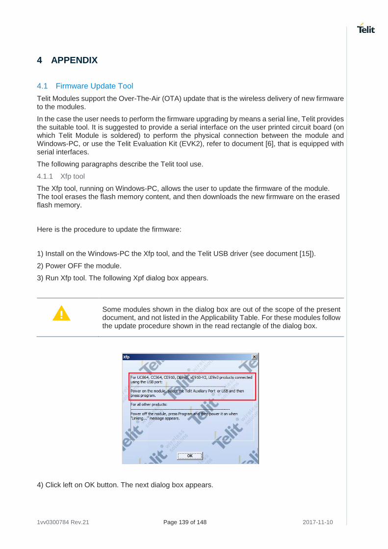
1vv0300784 Rev.21 Page 139 of 148 2017-11-10
4 APPENDIX
4.1 Firmware Update Tool
Telit Modules support the Over-The-Air (OTA) update that is the wireless delivery of new firmware to the modules.
In the case the user needs to perform the firmware upgrading by means a serial line, Telit provides the suitable tool. It is suggested to provide a serial interface on the user printed circuit board (on which Telit Module is soldered) to perform the physical connection between the module and Windows-PC, or use the Telit Evaluation Kit (EVK2), refer to document [6], that is equipped with serial interfaces.
The following paragraphs describe the Telit tool use.
4.1.1 Xfp tool
The Xfp tool, running on Windows-PC, allows the user to update the firmware of the module. The tool erases the flash memory content, and then downloads the new firmware on the erased flash memory.
Here is the procedure to update the firmware:
1) Install on the Windows-PC the Xfp tool, and the Telit USB driver (see document [15]).
2) Power OFF the module.
3) Run Xfp tool. The following Xpf dialog box appears.
Some modules shown in the dialog box are out of the scope of the present document, and not listed in the Applicability Table. For these modules follow the update procedure shown in the read rectangle of the dialog box.
4) Click left on OK button. The next dialog box appears.
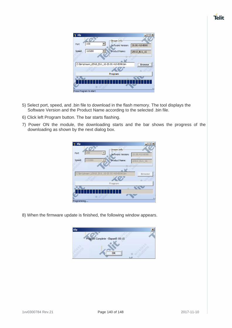
1vv0300784 Rev.21 Page 140 of 148 2017-11-10
5) Select port, speed, and .bin file to download in the flash memory. The tool displays the Software Version and the Product Name according to the selected .bin file.
6) Click left Program button. The bar starts flashing.
7) Power ON the module, the downloading starts and the bar shows the progress of the downloading as shown by the next dialog box.
8) When the firmware update is finished, the following window appears.
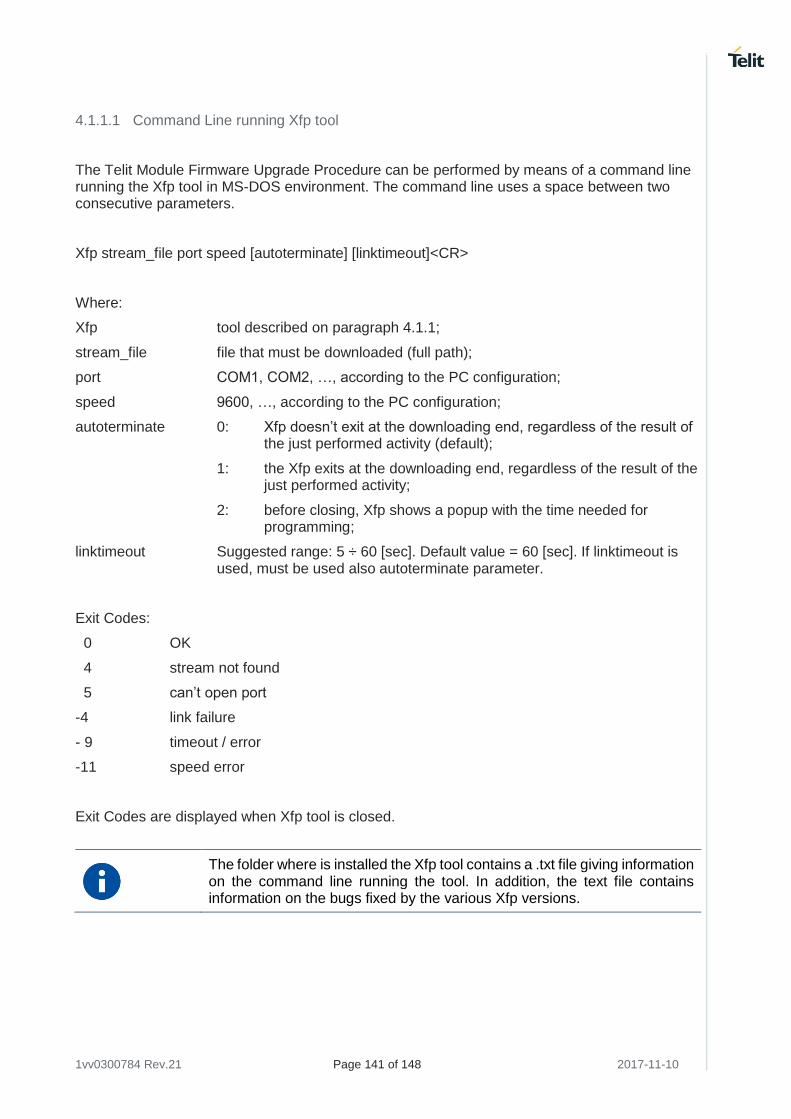
1vv0300784 Rev.21 Page 141 of 148 2017-11-10
4.1.1.1 Command Line running Xfp tool
The Telit Module Firmware Upgrade Procedure can be performed by means of a command line running the Xfp tool in MS-DOS environment. The command line uses a space between two consecutive parameters.
Xfp stream_file port speed [autoterminate] [linktimeout]<CR>
Where:
Xfp tool described on paragraph 4.1.1;
stream_file file that must be downloaded (full path);
port COM1, COM2, …, according to the PC configuration;
speed 9600, …, according to the PC configuration;
autoterminate 0: Xfp doesn’t exit at the downloading end, regardless of the result of the just performed activity (default);
1: the Xfp exits at the downloading end, regardless of the result of the just performed activity;
2: before closing, Xfp shows a popup with the time needed for programming;
linktimeout Suggested range: 5 ÷ 60 [sec]. Default value = 60 [sec]. If linktimeout is used, must be used also autoterminate parameter.
Exit Codes:
0 OK
4 stream not found
5 can’t open port
-4 link failure
- 9 timeout / error
-11 speed error
Exit Codes are displayed when Xfp tool is closed.
The folder where is installed the Xfp tool contains a .txt file giving information on the command line running the tool. In addition, the text file contains information on the bugs fixed by the various Xfp versions.
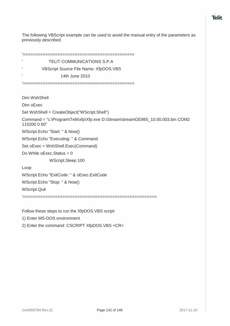
1vv0300784 Rev.21 Page 142 of 148 2017-11-10
The following VBScript example can be used to avoid the manual entry of the parameters as previously described.
'=============================================
' TELIT COMMUNICATIONS S.P.A
' VBScript Source File Name: XfpDOS.VBS
' 14th June 2010
'=============================================
Dim WshShell
Dim oExec
Set WshShell = CreateObject("WScript.Shell")
Command = "c:\Program\Telit\xfp\Xfp.exe D:\Stream\streamGE865_10.00.003.bin COM2 115200 0 60"
WScript.Echo "Start: " & Now()
WScript.Echo "Executing: " & Command
Set oExec = WshShell.Exec(Command)
Do While oExec.Status = 0
WScript.Sleep 100
Loop
WScript.Echo "ExitCode: " & oExec.ExitCode
WScript.Echo "Stop: " & Now()
WScript.Quit
'======================================================
Follow these steps to run the XfpDOS.VBS script:
1) Enter MS-DOS environment
2) Enter the command: CSCRIPT XfpDOS.VBS <CR>
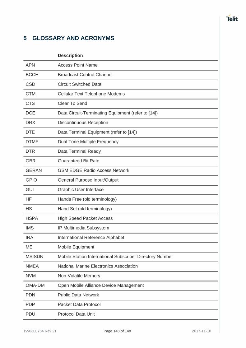
1vv0300784 Rev.21 Page 143 of 148 2017-11-10
5 GLOSSARY AND ACRONYMS
Description
APN Access Point Name
BCCH Broadcast Control Channel
CSD Circuit Switched Data
CTM Cellular Text Telephone Modems
CTS Clear To Send
DCE Data Circuit-Terminating Equipment (refer to [14])
DRX Discontinuous Reception
DTE Data Terminal Equipment (refer to [14])
DTMF Dual Tone Multiple Frequency
DTR Data Terminal Ready
GBR Guaranteed Bit Rate
GERAN GSM EDGE Radio Access Network
GPIO General Purpose Input/Output
GUI Graphic User Interface
HF Hands Free (old terminology)
HS Hand Set (old terminology)
HSPA High Speed Packet Access
IMS IP Multimedia Subsystem
IRA International Reference Alphabet
ME Mobile Equipment
MSISDN Mobile Station International Subscriber Directory Number
NMEA National Marine Electronics Association
NVM Non-Volatile Memory
OMA-DM Open Mobile Alliance Device Management
PDN Public Data Network
PDP Packet Data Protocol
PDU Protocol Data Unit
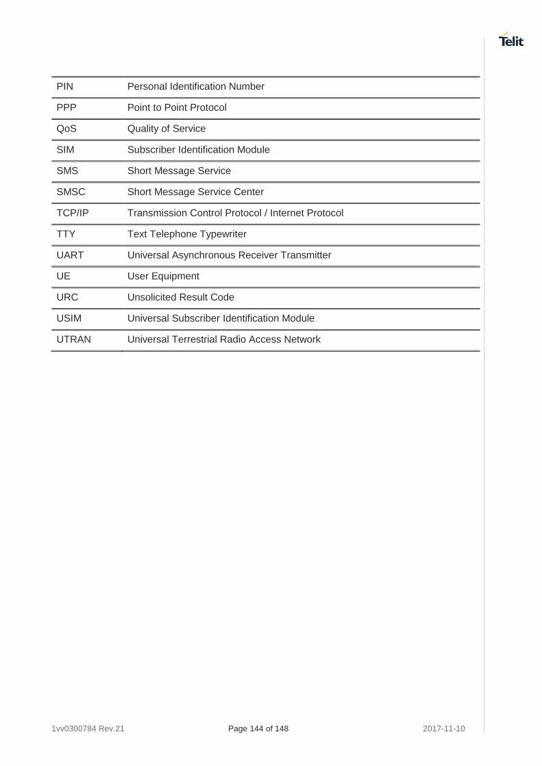
1vv0300784 Rev.21 Page 144 of 148 2017-11-10
PIN Personal Identification Number
PPP Point to Point Protocol
QoS Quality of Service
SIM Subscriber Identification Module
SMS Short Message Service
SMSC Short Message Service Center
TCP/IP Transmission Control Protocol / Internet Protocol
TTY Text Telephone Typewriter
UART Universal Asynchronous Receiver Transmitter
UE User Equipment
URC Unsolicited Result Code
USIM Universal Subscriber Identification Module
UTRAN Universal Terrestrial Radio Access Network
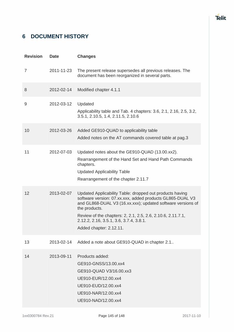
1vv0300784 Rev.21 Page 145 of 148 2017-11-10
6 DOCUMENT HISTORY
Revision Date Changes
7 2011-11-23 The present release supersedes all previous releases. The document has been reorganized in several parts.
8 2012-02-14 Modified chapter 4.1.1
9 2012-03-12 Updated
Applicability table and Tab. 4 chapters: 3.6, 2.1, 2.16, 2.5, 3.2, 3.5.1, 2.10.5, 1.4, 2.11.5, 2.10.6
10 2012-03-26 Added GE910-QUAD to applicability table
Added notes on the AT commands covered table at pag.3
11 2012-07-03 Updated notes about the GE910-QUAD (13.00.xx2).
Rearrangement of the Hand Set and Hand Path Commands chapters.
Updated Applicability Table
Rearrangement of the chapter 2.11.7
12 2013-02-07 Updated Applicability Table: dropped out products having software version: 07.xx.xxx, added products GL865-DUAL V3 and GL868-DUAL V3 (16.xx.xxx); updated software versions of the products.
Review of the chapters: 2, 2.1, 2.5, 2.6, 2.10.6, 2.11.7.1, 2.12.2, 2.16, 3.5.1, 3.6, 3.7.4, 3.8.1.
Added chapter: 2.12.11.
13 2013-02-14 Added a note about GE910-QUAD in chapter 2.1..
14 2013-09-11 Products added:
GE910-GNSS/13.00.xx4
GE910-QUAD V3/16.00.xx3
UE910-EUR/12.00.xx4
UE910-EUD/12.00.xx4
UE910-NAR/12.00.xx4
UE910-NAD/12.00.xx4
1vv0300784 Rev.21 Page 146 of 148 2017-11-10
Revision Date Changes
GL865-DUAL V3/16.00.xx2
GL865-QUAD V3/16.00.xx3
GL868-DUAL V3/16.00.xx2
15 2014-03-06 Products added:
GE910-QUAD AUTO / 13.00.xx4
GE866-QUAD / 16.00.xx3
UL865-EUR/EUD / 12.00.xx4
UL865-NAR/NAD / 12.00.xx4
UL865-N3G / 12.00.xx4
16 2014-09-09 Chapter 3.6: added CFUN 10, and 11
17 2015-02-24 Chapter 3.6: added a note about transition from CFUN 10/11 to CFUN 1
18 2015-05-08 Products added:
UE910 – N3G / 12.00.xx6
UE866 – N3G / 12.00.xx6
HE910 – GL / 12.00.xx6
Product removed:
HE910 – GA / 12.00.xx4
Chapter 2.5: added the baud rate 230400, 460800, 921600 for 3G modules.
19 2017-01-25 A new document format has been used and the entire document has been revised.
Power Saving chapter has been modified.
TCP/IP chapter (focusing on Default/Dedicated EPS Bearers, LE910 V2 series modules) has been added.
Firmware Update Tool chapter has been updated.
20 2017-05-02 Revision of chapters and pages numbering.
21 2017-11-10 Changed the format of the Applicability Table, and added the following modules series: LE910 Cat1, LE910 V2, LE866, ME866A1
1vv0300784 Rev.21 Page 147 of 148 2017-11-10
Revision Date Changes
Updated "Related Document" chapter.
The chapter 5 Connections has been removed.
The name of chapter 3 has been changed from "Basic AT Commands" in "AT Commands". The chapter 4 named "Advanced AT Commands" has been removed, but not its contents.
Moved the chapter "Firmware Update tool" into the new Appendix chapter.
Added new chapters related to 4G modules.
Added commands: #ENAOMADM, #HOSTODIS.

[04.2
016]
Mod. 0815


![V34 Software User Guide · [2] Telit SL869T3-I Product User Guide, 1VV0301546 [3] Telit SL869T3-I Evaluation Kit User Guide, 1VV0301561 [4] Telit V34 Software Authorized User Guide,](https://img.pdfslide.us/doc/110x75/5f12969a7038130c255e47aa/v34-software-user-guide-2-telit-sl869t3-i-product-user-guide-1vv0301546-3-telit.jpg)