Embed Size (px)
Citation preview

TELFONA,Contribution to Laminar Wing Development
for Future Transport Aircraft
K. H. HorstmannAeronautical Days, Vienna, 19th - 21st June 2006
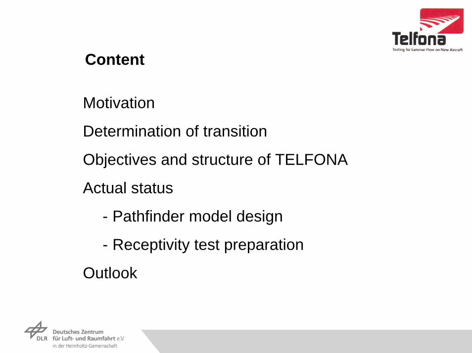
Content
Motivation
Determination of transition
Objectives and structure of TELFONA
Actual status
- Pathfinder model design
- Receptivity test preparation
Outlook

Drag reduction by laminar flow technology
More than half of the aircraft drag is caused by friction
Thus laminar flow technology has a high potential of drag reduction
Example A 340 (HLFC):
Wing: -12%Empenage -3%Nacelles: -1%
Potential of NLF is even higher but- restricted to smaller aircraft- and lower leading edge sweep angle
Problem for A/C development:- Prediction of transition (aircraft performance) not sufficiently reliable- Experimental validation even less reliable
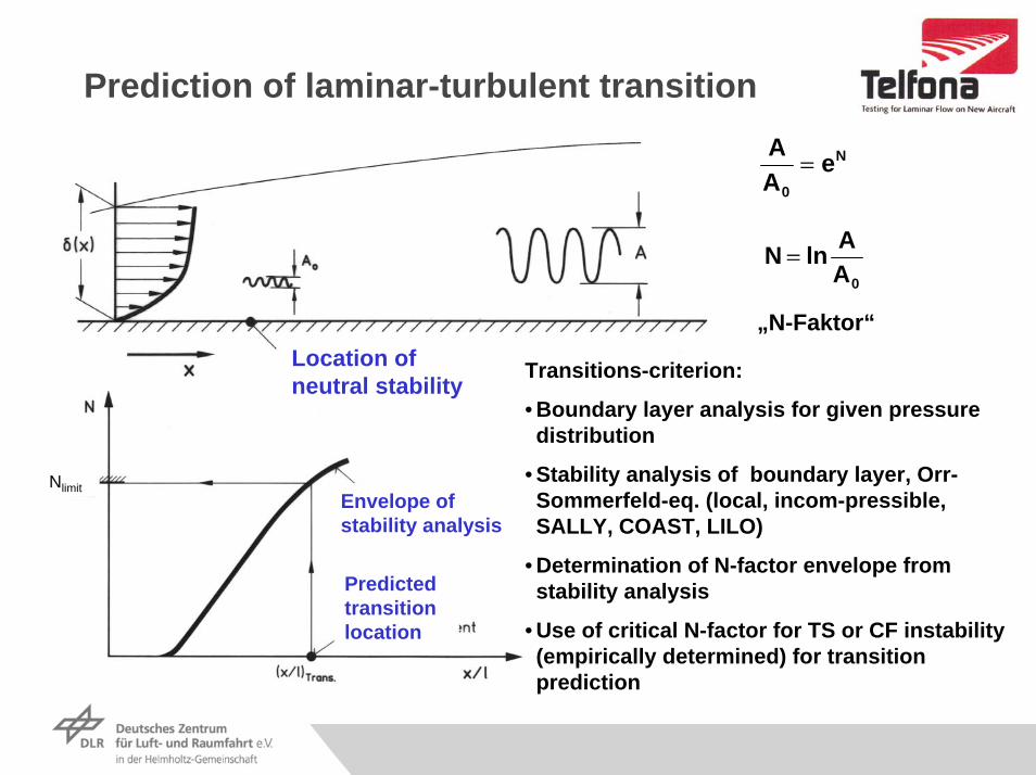
Prediction of laminar-turbulent transition
N
0
eAA
=
0AAlnN =
„N-Faktor“
Transitions-criterion:
• Boundary layer analysis for given pressure distribution
• Stability analysis of boundary layer, Orr-Sommerfeld-eq. (local, incom-pressible, SALLY, COAST, LILO)
• Determination of N-factor envelope from stability analysis
• Use of critical N-factor for TS or CF instability (empirically determined) for transition prediction
Location of neutral stability
Envelope of stability analysis
Predicted transition location
Nlimit

Limit N-Factors for flight and wind tunnel conditions
NLF und HLF in S1Ma
Stability analysis:• local, incompressible
•SALLY, COAST, LILO
•TSI in local flow direction
•CFI for f=0 Hz
NLF and HLF N-Factors substantially lower in wind tunnel than in flight
No critical N-factor data for ETW available

Objective of TELFONA:
ability to reliably predict NLF aircraft performance in flight based on wind tunnel tests and CFD results
by:
• Calibration of the ETW facility for testing laminar flow aircraft- Design and test a pathfinder wing- Determine transition inducing N-factors
• Integration of receptivity modeling into transition prediction methods- Understand and integrate effects of noise and turbulence in transition pred.
• Flight performance prediction methods for a laminar flow aircraft- Investigate scaling methods for flight performance prediction
• Validation of developed methods- Design and test a Performance wing (HARLS-wing)- Evaluate wind tunnel test results and prediction based on pathfinder data- Scale to flight performance
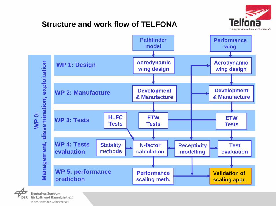
Structure and work flow of TELFONA
Pathfindermodel
Performancewing
WP
0:M
anag
emen
t, di
ssem
inat
ion,
exp
loita
tion Aerodynamic
wing designAerodynamic wing design
WP 1: Design
Development & Manufacture
WP 2: Manufacture Development & Manufacture
Validation ofscaling appr.
Performancescaling meth.
WP 5: performance prediction
ETWTests
ETWTestsWP 3: Tests HLFC
Tests
Testevaluation
N-factorcalculation
WP 4: Testsevaluation
Receptivitymodelling
Stabilitymethods
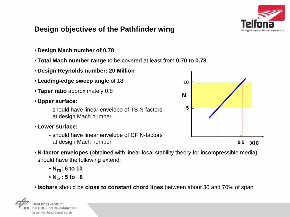
Design objectives of the Pathfinder wing
• Design Mach number of 0.78
• Total Mach number range to be covered at least from 0.70 to 0.78.
• Design Reynolds number: 20 Million
• Leading-edge sweep angle of 18°
• Taper ratio approximately 0.8
• Upper surface:- should have linear envelope of TS N-factors
at design Mach number
• Lower surface:- should have linear envelope of CF N-factors
at design Mach number
• N-factor envelopes (obtained with linear local stability theory for incompressible media) should have the following extend:
• NTS: 6 to 10• NCF: 5 to 8
• Isobars should be close to constant chord lines between about 30 and 70% of span
N
x/c0.5
10
5
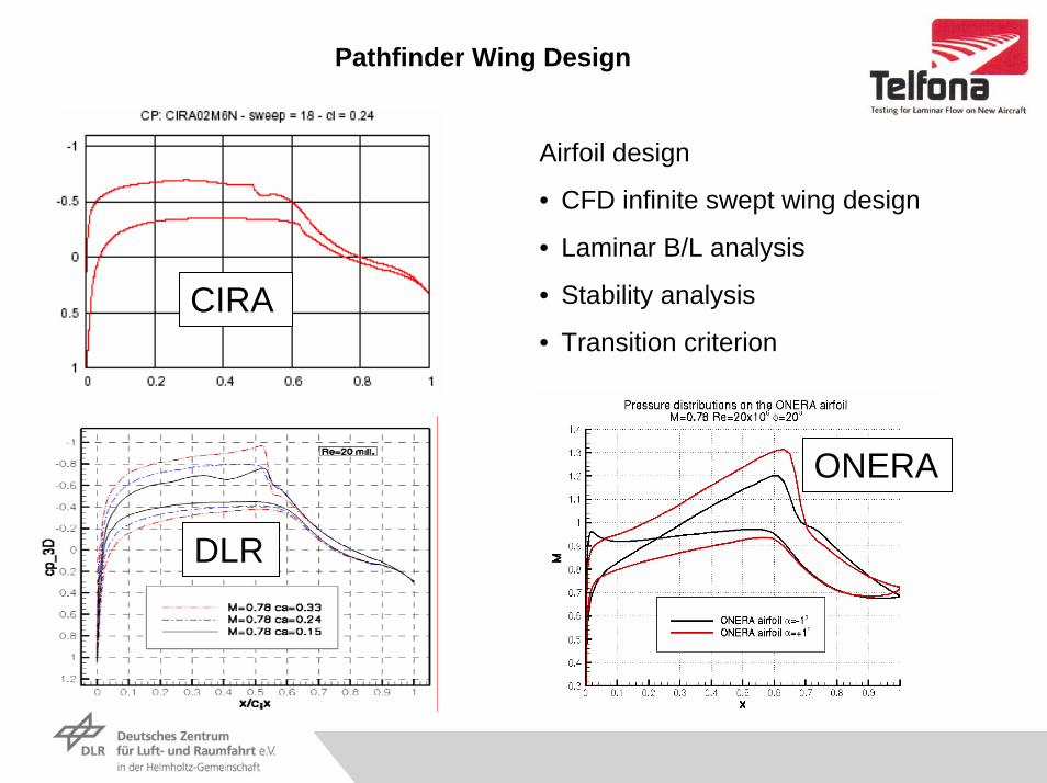
Pathfinder Wing Design
Airfoil design
• CFD infinite swept wing design
• Laminar B/L analysis
• Stability analysis
• Transition criterionCIRA
ONERA
DLR

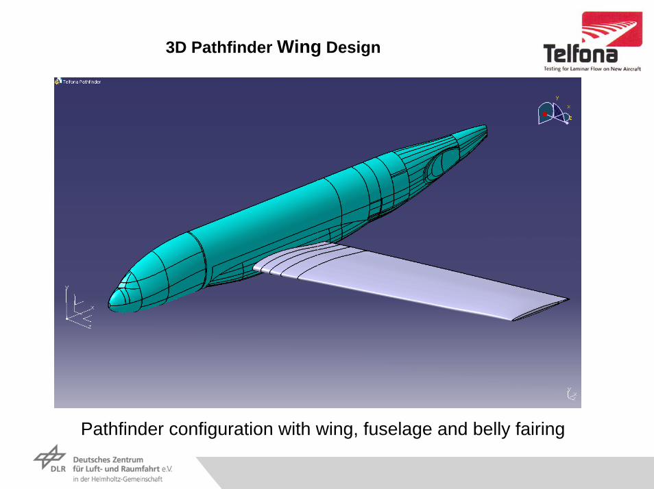
3D Pathfinder Wing Design
Geometrical Data of Pathfinder Wing Model

3D Pathfinder Wing Design
Parallel isobar design on upper and lower surface of pathfinder wing model (with fuselage and belly fairing)
Upper Surface Lower SurfaceUpper Surface Lower Surface
30% of span
70% of span
Fully inverse Design
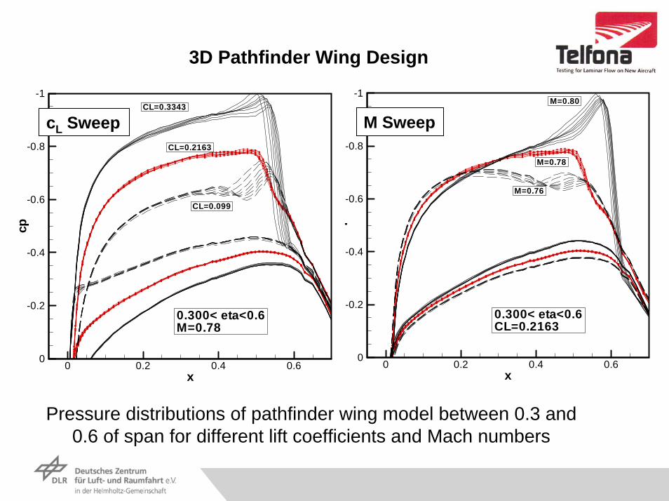
3D Pathfinder Wing Design
Pressure distributions of pathfinder wing model between 0.3 and 0.6 of span for different lift coefficients and Mach numbers
x
p
0 0.2 0.4 0.6
-1
-0.8
-0.6
-0.4
-0.2
0
0.300< eta<0.6CL=0.2163
M=0.76
M=0.78
M=0.80
x
cp
0 0.2 0.4 0.6
-1
-0.8
-0.6
-0.4
-0.2
0
0.300< eta<0.6M=0.78
CL=0.099
CL=0.2163
CL=0.3343
M SweepcL Sweep

3D Pathfinder Wing Design
Isobar evolution at upper surface of pathfinder wing model at design conditions with four degree yaw angle

3D Pathfinder Wing Design
Pressure Distributions of Pathfinder Wing at Design Conditions with four Degree Yaw Angle
M= 0.78β=4o
Rec=20 mill.cL= 0.2174
x/c
c p
0 0.2 0.4 0.6
-1
-0.8
-0.6
-0.4
-0.2
0
0.300< η<0.6M=0.78, CL=0.2163 (β=0o)
β=4o (right wing)
β=0o
β=4o (left wing)
3D Pathfinder Wing Design
Pathfinder configuration with wing, fuselage and belly fairing
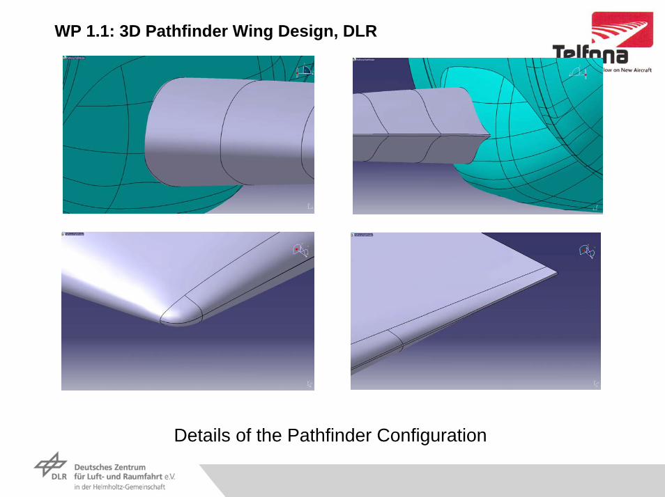
WP 1.1: 3D Pathfinder Wing Design, DLR
Details of the Pathfinder Configuration

B/L receptivity investigationPreparation of test in PETW with different turbulence and noise levels:
•Modification of turbulence level by additional grids in PETW
•Measurement of free stream turbulence, noise and pressure fluctuations
•NLF airfoil for M=0.78 and Re=8.3 Mio
•Measurement of surface sheer stress fluctuations
- Very high disturbance frequencies of TS waves up to more than 100 kHz
- Very short wave lengths below 2 mm
- Standard sensors not applicable
- Use of Piezo sensors
•Modification of TS waves show B/L receptivity

Outlook (I)
Expected results of TELFONA:
• Experience in the laminar wing design process
• Validation of CFD methods for laminar flow technology
• Validation of wind tunnel testing (ETW) of laminar flow wing (NLF)
• Reliable scaling method(s) for wind tunnel to flight extrapolation
• Knowledge of receptivity of B/L for noise and turbulence
• Knowledge of performance of NLF HARLS wing
• TELFONA results are also applicable on laminar nacelle
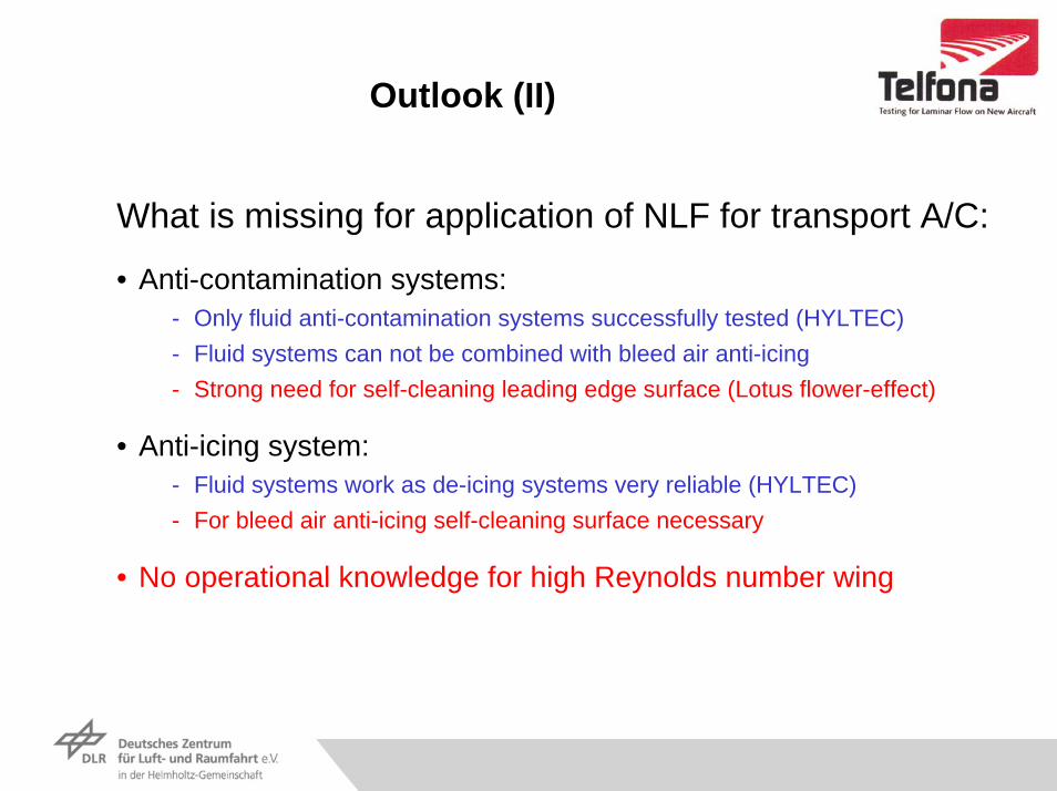
Outlook (II)
What is missing for application of NLF for transport A/C:
• Anti-contamination systems:- Only fluid anti-contamination systems successfully tested (HYLTEC)- Fluid systems can not be combined with bleed air anti-icing- Strong need for self-cleaning leading edge surface (Lotus flower-effect)
• Anti-icing system:- Fluid systems work as de-icing systems very reliable (HYLTEC)- For bleed air anti-icing self-cleaning surface necessary
• No operational knowledge for high Reynolds number wing