Embed Size (px)
Citation preview

Telex�
Operating Instructions
FMR-10 SERIESWIRELESS USER GUIDE
Channel
Diversity
Audio
RF
A
B
1 2 3 4
-20 -10 0 +3
TelexR
CLEAR
SCANTM
FMR-10
Telex
POWER
BAT .NO
A U D I O
Telex WT-10 UHF
TRANSMITTER
R


Table of ContentsSection Page
1. Quick System Setup Guide . . . . . . . . . . . . . . . . . . . . . . . 12. System Description . . . . . . . . . . . . . . . . . . . . . . . . . . . . . 33. Detailed system/component setup instructions . . . . . . . . 4
3.1. FMR-10 Receiver Setup and Operation . . . . . . . . . . 43.1.1 Rack Mount Installation . . . . . . . . . . . . . . . . . . . 73.1.2 Antenna Placement . . . . . . . . . . . . . . . . . . . . . . . 9
3.2. Handheld Transmitter Setup . . . . . . . . . . . . . . . . . . 113.3. Bodypack Transmitter Setup . . . . . . . . . . . . . . . . . 13
4. Guidelines/Recommendations for Best Performance . . 165. Troubleshooting Guide . . . . . . . . . . . . . . . . . . . . . . . . . 186. Technical Specifications . . . . . . . . . . . . . . . . . . . . . . . . 19
FCC Information . . . . . . . . . . . . . . . . . . . . . . . . . . . . . . 20Accessories and Replacement Parts. . . . . . . . . . . . . . . . 21
1. Quick System Setup Guide
Receiver SetupReceiver Setup
1. Plug power supply cord into the back of the receiver and plug thepower supply into an outlet. The channel display & red/green“Diversity” light on the receiver front panel should light up.
2. Attach the supplied 1/4 wave antenna’s to the FMR-10 receiver.Orient the receive antennas angled up and away from each other(at a 90 degree angle). For specific receiver setup information, re-fer to section 3.1 for the FMR-10 receiver. Assure that your trans-mitter(s) are turned OFF.
3. Depress “SET” button on front panel and release when channeldisplay starts to flash (about 3 seconds). This activates“ClearScan™” to find an interference free channel for operation.Note the channel (0 - 9) shown on the receiver front panel channeldisplay.
4. Connect receiver audio output to mixer or amplifier. Mute or re-duce mixer gain.
-1-
Transmitter SetupTransmitter Setup
1. Open battery compartment, install 9 Volt battery. Make sure toobserve proper battery polarity.
2. Adjust channel setting to match channel number shown on re-ceiver channel display. Replace battery cover.
3. If using bodypack transmitter, plug the microphone into the trans-mitter connector.
Operating the SystemOperating the System
1. Turn transmitter ON via the ON/OFF switch. After a few sec-onds, the yellow “Tx On” light should illuminate on the receiverfront panel.
2. Turn audio switch to the ON position to the audio.
3. Set mixer amp gain to normal position.
4. Talk/sing into the microphone at a normal volume. You shouldhear audio coming out of the system.
5. If the signal is distorted, turn the gain adjust control on the trans-mitter down. If the signal level is low, you may need to turn thegain adjust control up.
-2-
2. System Description
The Telex FMR-10 Wireless is a series of 10 channel frequency agileUHF wireless systems that combine Telex’s legendary quality andreliability with high value. The transmitters and receivers operate inthe UHF frequency range. The well-designed audio circuitry ensuresexcellent signal-to-noise ratio with accurate sound quality.
System FeaturesSystem Features
· 10 Channel Frequency Agile UHF system operation.
· Featuring “ClearScan™” which makes for quick and easy system
setup.
· Handheld transmitters feature Electro-Voice N/DYM mic ele-
ments, for superior sound quality.
· True-diversity system with Posi-Phase™ insures maximum range
and freedom from interference.
· Well-designed companding and audio circuitry insures high sig-
nal-to-noise ratio and excellent sound quality.
· Receivers may be rack-mounted with included hardware.
· FMR-10 output via 3-pin XLR-type balanced mic level connector.
-3-

3. Detailed Setup Instructions
3.1 FMR-10 Receiver Setup & OperationReceiver Setup & Operation
1. Place the receiver where there is a clear line of sight to the areawhere the transmitter will be used.
2. Attach either the supplied 1/4-wave antennas or two remotelymounted antennas to the antenna connectors on the rear panel of theFMR-10. Be sure and tighten the connectors securely. If the supplied1/4-wave antennas are used, they must be oriented at a 90o angle asshown in Figure 2. Unlike other diversity wireless systems, twoantennas are required for the FMR-10 to operate correctly.
3. Connect the power supply cord to the receiver. Plug the powersupply into an AC outlet. Confirm that the receiver is ON bychecking for the lighted channel display and diversity led’s on thefront panel.
NOTE: Upon power-up, the receiver will return to the channel itwas set to when it was turned off.
-4-
CHANNELDISPLAY
CHANNELSET
BUTTON
SET ANTENNASAT 90 DEGREES
Channel
Diversity
Audio
RF
A
B
1 2 3 4
-20 -10 0 +3
DIVERSITYLIGHTS RF METER
AUDIO METER
LOCK OUT INDICATOR
TelexR
CLEAR
SCANTM
FMR-10
Madein
U.S.A.
BalancedMic LevelOutput
Power12-15 V AC/DC
700 mA
Squelch
llll llll llll
llll lllllll llll
BALANCEDAUDIO
OUTPUT
POWERJACK
SQUELCHCONTROL
Antenna Antenna
Telex FMR-10R
F CC Tested to Complywith FCC Standards
Canada
Patent Pending
Figure 1 FMR-10 Front View
Figure 2 FMR-10 Rear View
CAUTION: Please make sure that the AC adapter is the cor-rect voltage for your local requirements.
4. ClearScan™: The FMR-10 Wireless system featuresClearScan™. ClearScan™ automates the process of finding aclear channel to use in setup of your FMR-10 Wireless system. Touse ClearScan™, depress and hold down the set button for 3 sec-onds. When the channel display begins flashing release the setbutton. The receiver is now searching for a clear frequency bymeasuring the RF energy present on each channel. The entire pro-cess will take about 5 seconds. While scanning, the channel dis-play will show the channel number being scanned. WhenClearScan™ is complete, the display will stop flashing and it willdisplay the number of the channel recommended for use.
NOTE: If using more than one FMR-10 system, set up ONE sys-tem at a time. Turn on the transmitter for the first system, beforeusing ClearScan™ to set up the second. Please see the “Guide-line/Recommendations for best performance” section of theFMR-10 User’s Guide to set up more than two systems.
5. Setting the Channel: Changing the channel on the receiver canalso be done manually. By momentarily depressing the set but-ton, the channel number is increased by one.
NOTE: when the system is turned off, the channel number issaved in non-volatile memory. When the receiver is turned on, itwill return to the same channel number.
6. Channel Change Lock-out: Once the channel has been set onthe receiver, the FMR-10 system has the capability to deactivateor lock-out the channel change button. This is done by depressingthe set button for 10 seconds or more. Lock-out is active when thedecimal point illuminates in the lower right corner of the channeldisplay. This will defeat the set button. To override or defeat thelockout function, again depress the set button for 10 seconds. Thiswill reactivate the channel set button to work normally. Thisfunction can be useful where unauthorized personnel have accessto the receiver.
-5-
NOTE: If thesystemis in“lock-out”,ClearScan™ willnot function.
7. Make sure the gain setting is muted or turned down on the mixeror amp channel you will connect the wireless system to.
8. Plug the audio cable (not supplied) into the output connector.
NOTE: The 3-pin XLR-type connector output level is fixed, andcannot be adjusted.
Now refer to details located in the FMR-10 User’s Guide onhow to set up the transmitter.
Once the Transmitter has been set-up, and turned on...
9. Speak or sing loudly into the microphone and observe the Audiolevel meter on the receiver. Adjust the gain control on the trans-mitter to prevent over or under modulation. The gain should beadjusted so that the signal peaks are no more than -10dB and thatthere is at least -20dB or audio level meter indication.
10. “Walk” the expected area of use to check for dropouts or interfer-ence. To minimize the potential for dropouts or interference,please observe good antenna placement. When the transmitter isturned on, the RF meter on the receiver should be illuminated inthe green range to verify it is receiving a strong signal.
11. Adjust the squelch control if necessary. The squelch control onthe back of the receiver may be adjusted to effectively increaserange or to reduce interference. The factory setting is at a mid-point, which should be suitable for most situations. To effectivelyincrease range, turn the control counter-clockwise until you hearnoise or interference, then, turn the squelch clockwise until thenoise is muted. To reduce interference, turn the control clock-wise.
NOTE: If the squelch is being adjusted, the transmitter should beturned off.
CAUTION! Increasing the range will make the system moresusceptible to outside interference! Reducing interferencewill also effectively decrease the range, which will make thesystem more susceptible to dropouts.
-6-

3.1.1 Rack Mount Installation3.1.1 Rack Mount Installation
The FMR-10 is supplied with rack mounts for single and double mount-ing in a standard EIA 19”/ 483mm equipment rack (see Figure 3).
For rack mounting a single unit, a long and short “ear” are used. Fordual side-by-side mounting, use the short “ears” and the mid sizedbrackets from two FMR-10 as shown.
To assemble the rack mount adapters to the unit(s) and install into arack, proceed as follows:
1. Remove the front Phillips head screws from each side of each unit.
2. Align the correct rack ear or bracket with the holes on the side ofthe unit. Install the previously removed screws. Insert an addi-tional screw (provided in the parts pack) into the remaining hole.Repeat this step for the opposite side of the unit. Be sure to tightenall screws securely.
For double mounting of two systems, proceed as follows:
1. Align the mid-sized brackets (Item #2) with the holes on the adja-cent sides of each unit.
-7-
(TYPICAL BOTH SIDES)
(TYPICAL ALL SIDES)
1
1
4
REMOVE SCREWS(TYPICAL 4 SIDES)
2
5
65
6
6
3
FMR-10
CLEARSCAN
1
2
3
4
Diversity
AUDIO
Channel
FMR-10
CLEARSCAN
Diversity
AUDIO
Channel
1
2
3
4
Figure 3Rack Mount Installation

2. Install the previously removed screws. Insert an additional screw(provided in the parts pack) into the remaining holes. Tighten allscrews securely.
3. Place the two assemblies side-by-side with the mid brackets to-gether. (The left bracket should fit above the right so that thecountersinks are visible). Install 4 flat-head screws (Item #5) andtighten them securely.
4. Attach the antenna connectors to the brackets.
5. Attach the supplied extension cables from the rack connectors tothe antenna connections on the back of the receiver.
6. Place the assembly into the rack enclosure and insert 4 #10-32 x3/8” Phillips pan head screws (supplied) in each corner of the rackears and secure to the enclosure. Some rack enclosures requiremetric screws which are not supplied.
-8-
FMR-10
Diversity
AUDIO
Channel
FMR-10
Diversity
AUDIO
Channel
Figure 4

3.1.2 Antenna Placement3.1.2 Antenna Placement
For any wireless system to perform correctly, strong RF signals aremandatory. To maximize signal strength, good antenna placementmust be utilized. Although some situations prohibit perfect antennaplacement, here are some guidelines:
1. The antennas should be placed in a location with a clear signalpath to the transmitter. Walls, ceilings, metal objects, equipmentracks, etc. are all signal barriers that will reduce range and perfor-mance. Generally speaking, placing the receiver at an elevated lo-cation can help increase range and signal strength.
2. If the receiver is rack-mounted, external antennas are neces-sary. Do not rack mount the FMR-10 with the antennasmounted directly on the back of the unit. This will severelydecrease the range and performance of the system.
If the FMR-10 is rack-mounted, make sure the antennas arefront-mounted (following the directions noted above). If anten-nas are mounted remotely from the chassis, the 1/4-wave anten-nas supplied with the receiver cannot be used. 1/2-wave antennasare a necessity if the antennas are remote-mounted and can pro-vide better performance when used with the rack mount.
-9-
Figure 51/2-Wave antenna for Remote Mounting
Figure 6

If antennas are remote-mounted, separating them 6 feet (1.8m) ormore and keeping them at least 2 feet (.6m) from other barriers willimprove performance (see Figure 8). If you are remote mountingthe antennas and require strong signal over a large area, considerusing highly directional antennas such as a log-periodic. TheALP-450 available from Telex is tuned for frequencies from450-900 MHz and can provide an additional 5 dB of gain.
3. If you remote-mount the antennas, attention should be paid to thetype and quality of the antenna cable. For cable runs longer than25-ft. (7.6m), special low-loss cables should be used.
4. If multiple wireless systems are being used, a multi-coupler willminimize antenna interference. A multi-coupler has one set of an-tennas and distributes RF signal to multiple systems. The Telexwill supply antenna signal and DC power to 4 systems, eliminat-ing 3 external power supplies and 6 antennas.
-10-
SIDEMOUNTING
BRACKET SHOULD BEAT TOP OF MOUNTINGSURFACE.
MICROPHONE STANDMOUNTING
Figure 7
2 FT (60 CM)MINIMUMDISTANCE
MINIMUMDISTANCE
6 FT (2 METERS)
TelexR
CLEAR
SCANTM
FMR-10
Channel
Diversity
A
B
RF
AUDIO
1 2
-20 -10 0 +3
3 4
TelexR
CLEAR
SCANTM
FMR-10
Channel
Diversity
A
B
RF
AUDIO
1 2
-20 -10 0 +3
3 4
Figure 8
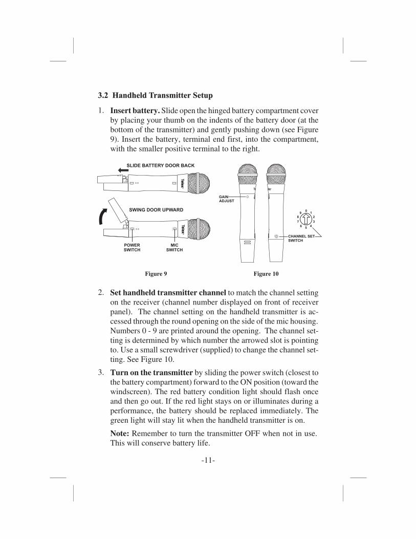
3.2 Handheld Transmitter Setup3.2 Handheld Transmitter Setup
1. Insert battery. Slide open the hinged battery compartment coverby placing your thumb on the indents of the battery door (at thebottom of the transmitter) and gently pushing down (see Figure9). Insert the battery, terminal end first, into the compartment,with the smaller positive terminal to the right.
2. Set handheld transmitter channel to match the channel settingon the receiver (channel number displayed on front of receiverpanel). The channel setting on the handheld transmitter is ac-cessed through the round opening on the side of the mic housing.Numbers 0 - 9 are printed around the opening. The channel set-ting is determined by which number the arrowed slot is pointingto. Use a small screwdriver (supplied) to change the channel set-ting. See Figure 10.
3. Turn on the transmitter by sliding the power switch (closest tothe battery compartment) forward to the ON position (toward thewindscreen). The red battery condition light should flash onceand then go out. If the red light stays on or illuminates during aperformance, the battery should be replaced immediately. Thegreen light will stay lit when the handheld transmitter is on.
Note: Remember to turn the transmitter OFF when not in use.This will conserve battery life.
-11-
SLIDE BATTERY DOOR BACK
SWING DOOR UPWARD
POWERSWITCH
MICSWITCH
TelexR
elexTelex
R
elex
Figure 9
GAINADJUST
9 10
2
3
45
6
7
8 CHANNEL SETSWITCH
9 10
2
3
45
6
7
8
elex RTelex
Figure 10

4. Verify Reception. When the transmitter is turned on: (FMR-10)the RF meter will illuminate, indicating that the receiver is pick-ing up the signal. If this does not happen, make sure that the trans-mitter and receiver are set to the same channels.
5. Unmute the audio by sliding the audio switch (immediately be-low the mic element) towards the windscreen. Speak or sing intothe microphone and you should hear your voice through the PA /sound system.
6. Adjustment of the transmitter audio gain - if necessary. Thetransmitter audio gain is set to a mid level which should be suit-able for most situations. However, for loud or soft speakers orsingers, an adjustment may be necessary. First, speak or sing intothe microphone and listen closely. If the gain is too high, you willhear distortion, and if the gain is too low, the signal will be low. Ineither situation, an adjustment may be necessary.
To adjust the transmitter gain, gently insert the provided screw-driver (or other 3/32-in./2.4mm screwdriver) into the hole nearthe head of the transmitter (see Figure 12). Turn lightly until thescrewdriver tip drops into the slot in the level control. Gently turncounterclockwise until the control stops (the mic output is attenu-ated but not “off”). Slowly turn the mic-level control up while lis-tening to the audio. If the audio becomes distorted, turn the miclevel control down (counter-clockwise) about 1/8 turn.
Note: Operate with the transmitter audio gain set as high as possi-ble without distortion, for the best signal to noise ratio.
7. Test performance. Check to see that the RF meter on theFMR-10 receiver is illuminated, an indication that the receiver ispicking up the signal. Then, “walk” the intended area of use andmake sure that there are no barriers to reception or sources of in-terference. If problems are encountered, see TroubleshootingGuide.
-12-

3.3 Bodypack Transmitter SetupTransmitter Setup
1. Insert battery. Open the hinged battery compartment by placingyour thumb or finger on the indent labeled OPEN on the batterydoor and pushing down, see Figure 11. When inserting the bat-tery, pay attention to the polarity (+/-) and insert the terminalsinto the battery compartment first. Close the battery door by slid-ing the door shut.
2. Set the transmitter channel to match the channel setting on thereceiver. The channel switch on the bodypack is located just un-derneath the battery door, and to the right of the indent labeledOPEN. Note the channel number label (0-9) surrounding theopening. The bodypack channel must be set to the same numberas the receiver channel, which is displayed on the receiver frontpanel. The channel setting is determined by which number thearrowed slot is pointing to. Use a small screwdriver (supplied)to change the channel setting.
-13-
BELT CLIP MAY BE TURNED90 DEGREES BY REMOVINGSCREW AND REINSTALLINGHERE.
GAINADJUSTMENT
DOOR OPENEDBUT NOTSWUNG UPWARD
SWING DOORUPWARD TOACCESS BATTERYCOMPARTMENT
TO OPEN BATTERY DOORPRESS ARROW WITH INDEXFINGER AND PULL DOWN WITHTHUMB AND MIDDLE FINGER
CHANNELSWITCH
Figure 11Channel Switch
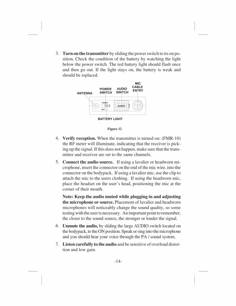
3. Turn on the transmitter by sliding the power switch to its on po-sition. Check the condition of the battery by watching the lightbelow the power switch. The red battery light should flash onceand then go out. If the light stays on, the battery is weak andshould be replaced.
4. Verify reception. When the transmitter is turned on: (FMR-10)the RF meter will illuminate, indicating that the receiver is pick-ing up the signal. If this does not happen, make sure that the trans-mitter and receiver are set to the same channels.
5. Connect the audio source. If using a lavalier or headworn mi-crophone, insert the connector on the end of the mic wire, into theconnector on the bodypack. If using a lavalier mic, use the clip toattach the mic to the users clothing. If using the headworn mic,place the headset on the user’s head, positioning the mic at thecorner of their mouth.
Note: Keep the audio muted while plugging in and adjustingthe microphone or source. Placement of lavalier and headwornmicrophones will noticeably change the sound quality, so sometesting with the user is necessary. An important point to remember,the closer to the sound source, the stronger or louder the signal.
6. Unmute the audio, by sliding the large AUDIO switch located onthe bodypack, to the ON position. Speak or sing into the microphoneand you should hear your voice through the PA / sound system.
7. Listen carefully to the audio and be sensitive of overload distor-tion and low gain.
-14-
POWER
O
POWERSWITCH
AUDIOSWITCH
MICCABLEENTRY
BATTERY LIGHT
N
BAT.
OFF
AUDIO
ANTENNA
Figure 12
8. Adjust the transmit gain if necessary. Gently insert the pro-vided screwdriver or other 3/32-in. 2.4mm screwdriver into thegain adjustment located at the top edge of the battery compart-ment under the door (see Figure 11). The door has to be openedbut not swung upward to make adjustments. Turn lightly until thescrewdriver tip drops into the slot on the level control. Gently turnthe control counterclockwise until the control stops (the audiooutput is attenuated but not “off”). Slowly turn the audio levelcontrol clockwise while listening to audio; if the audio becomesdistorted, turn the mic level control counter-clockwise about 1/8turn.
9. Test performance. Check to see that the RF meter on theFMR-10 receiver is illuminated, an indication that the receiver ispicking up the signal. Then, “walk” the intended area of use andmake sure that there are no barriers to reception or sources of in-terference. If problems are encountered, see TroubleshootingGuide.
10. Clip the bodypack to the user’s belt or pocket. The bodypackcan be positioned horizontally or vertically by moving the beltclip attachment. This is done by removing the belt clip attachmentscrew, rotating the clip to the desired position, and replacing thescrew.
-15-
4. Guidelines/Recommendations for Best Performance
Compatibility
The receiver and transmitter must be set to the same channel to oper-ate together.
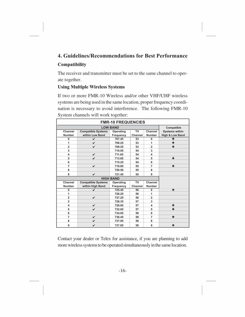
Using Multiple Wireless SystemsUsing Multiple Wireless Systems
If two or more FMR-10 Wireless and/or other VHF/UHF wirelesssystems are being used in the same location, proper frequency coordi-nation is necessary to avoid interference. The following FMR-10System channels will work together:
Contact your dealer or Telex for assistance, if you are planning to addmorewireless systems tobeoperatedsimultaneously in thesamelocation.
-16-
FMR-10 FREQUENCIES
LOW BAND Compatible
Channel Compatible Systems Operating TV Channel Systems within
Number within Low Band Frequency Channel Number High & Low Band
0 ✔ 707.45 53 0 ✚
1 ✔ 708.25 53 1 ✚
2 ✔ 709.25 53 2 ✚3 710.05 54 3
4 ✔ 711.65 54 4
5 ✔ 713.85 54 5 ✚6 715.25 54 6
7 ✔ 718.85 55 7 ✚8 720.50 55 8
9 ✔ 721.45 55 9
HIGH BANDChannel Compatible Systems Operating TV Channel
Number within High Band Frequency Channel Number
0 ✔ 725.45 56 0 ✚1 726.25 56 1
2 ✔ 727.25 56 2
3 728.35 57 3
4 ✔ 729.65 57 4 ✚
5 ✔ 732.65 57 5 ✚6 734.05 58 6
7 ✔ 736.45 58 7 ✚8 ✔ 737.05 58 8
9 ✔ 737.85 58 9 ✚

Multiple System Setup &Multiple System Setup & ClearScan™
ClearScan™ is most useful for finding operating frequencies for situ-ations where no more than 2 systems will be used simultaneously.
When setting up more than 2 systems, use ClearScan™ to choose thefirst channel of operation. Set up subsequent systems following thechannel groupings listed above in the “Using Multiple Wireless Sys-tems” section.
Potential Sources of InterferencePotential Sources of Interference
There are many potential sources of interference for your wirelesssystem. Any electronic product that contains digital circuitry includ-ing digital signal processors (reverb/multi-effects units), electronickeyboards, digital lighting controllers, CD players and computers, allemit RF energy that can adversely affect the performance of yourwireless system. It is always best to place your receiver as far awayfrom these devices as possible to minimize this potential source ofproblems.
-17-
Battery RecommendationsBattery Recommendations
Fresh 9-volt alkaline batteries from a quality manufacturer will yieldthe best performance from your FMR-10 transmitters. Rechargeable8.4-volt Ni-cad batteries can be used, but will yield much shorter op-erational time.
When the transmitter switch is turned on, the red battery light willflash once if the battery is good. If the light does not flash or stays litcontinuously, the battery is weak or dead. If the light comes on duringuse, the battery is weakening and should be replaced as soon as possi-ble.
If sound quality degrades during use, it may be the result of a weaken-ing battery.
Receiver and Antenna PlacementReceiver and Antenna Placement
Do not place the receiver near a large metal object or surface.Locate the receiver as close as possible to the area where the Trans-mitter user will be working. Ideally, position the receiver so that thetransmitter is within site of the receiver.
When using multiple systems, do not allow antennas to cross or toucheach other.
-18-
-19-
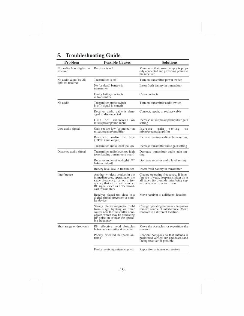
5. Troubleshooting Guide
Problem Possible Causes SolutionsNo audio & no lights onreceiver
No audio & no Tx ONlight on receiver
No audio
Low audio signal
Distorted audio signal
Interference
Short range or drop-outs
Receiver is off
Transmitter is off
No (or dead) battery intransmitter
Faulty battery contactsin transmitter
Transmitter audio switchis off (signal is muted)
Receiver audio cable is dam-aged or disconnected
Gain not suff ic ient onmixer/preamp/amp input.
Gain set too low (or muted) onmixer/preamp/amplifier
Receiver audio too low(1/4”/6.4mm output)
Transmitter audio level too low
Transmitter audio level too high(overloading transmitter circuit)
Receiver audio set too high (1/4”6.4mm output)
Battery level low in transmitter
Another wireless product in theimmediate area, operating on thesame frequency, or on a fre-quency that mixes with anotherRF signal (such as a TV broad-cast transmitter).
Receiver placed too close to adigital signal processor or simi-lar device.
Strong electromagnetic fieldfrom stage lighting or othersource near the transmitter or re-ceiver, which may be producingRF noise on or near the operat-ing frequency.
RF reflective metal obstaclesbetween transmitter & receiver.
Poorly oriented beltpack an-tenna
Faulty receiving antenna system
Make sure that power supply is prop-erly connected and providing power tothe receiver
Turn on transmitter power switch
Insert fresh battery in transmitter
Clean contacts
Turn on transmitter audio switch
Connect, repair, or replace cable
Increase mixer/preamp/amplifier gainsetting
Increase gain set t ing onmixer/preamp/amplifier
Increase receiver audio volume setting
Increase transmitter audio gain setting
Decrease transmitter audio gain set-ting
Decrease receiver audio level setting
Insert fresh battery in transmitter
Change operating frequency. If inter-ference is weak, keep transmitter on atall times (to override interfering sig-nal) whenever receiver is on.
Move receiver to a different location
Change operating frequency. Repair orremove source of interference. Movereceiver to a different location.
Move the obstacles, or reposition thereceiver
Reorient bodypack so that antenna ispositioned vertical (up and down) andfacing receiver, if possible
Reposition antennas or receiver
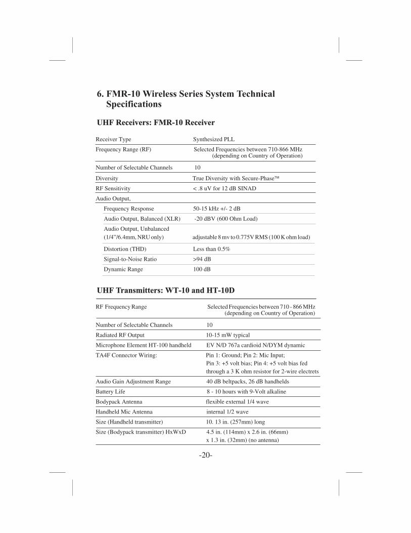
6. FMR-10 Wireless Series System TechnicalSpecifications
UHF Receivers:UHF Receivers: FMR-10 Receiver
UHF Transmitters:UHF Transmitters: WT-10 and HT-10Dand HT-10D
-20-
Receiver Type Synthesized PLL
Frequency Range (RF) Selected Frequencies between 710-866 MHz(depending on Country of Operation)
Number of Selectable Channels 10
Diversity True Diversity with Secure-Phase�
RF Sensitivity < .8 uV for 12 dB SINAD
Audio Output,
Frequency Response 50-15 kHz +/- 2 dB
Audio Output, Balanced (XLR) -20 dBV (600 Ohm Load)
Audio Output, Unbalanced(1/4”/6.4mm, NRU only) adjustable 8 mv to 0.775V RMS (100 K ohm load)
Distortion (THD) Less than 0.5%
Signal-to-Noise Ratio >94 dB
Dynamic Range 100 dB
RF Frequency Range Selected Frequencies between 710 - 866 MHz(depending on Country of Operation)
Number of Selectable Channels 10
Radiated RF Output 10-15 mW typical
Microphone Element HT-100 handheld EV N/D 767a cardioid N/DYM dynamic
TA4F Connector Wiring: Pin 1: Ground; Pin 2: Mic Input;Pin 3: +5 volt bias; Pin 4: +5 volt bias fedthrough a 3 K ohm resistor for 2-wire electrets
Audio Gain Adjustment Range 40 dB beltpacks, 26 dB handhelds
Battery Life 8 - 10 hours with 9-Volt alkaline
Bodypack Antenna flexible external 1/4 wave
Handheld Mic Antenna internal 1/2 wave
Size (Handheld transmitter) 10. 13 in. (257mm) long
Size (Bodypack transmitter) HxWxD 4.5 in. (114mm) x 2.6 in. (66mm)x 1.3 in. (32mm) (no antenna)
-21-
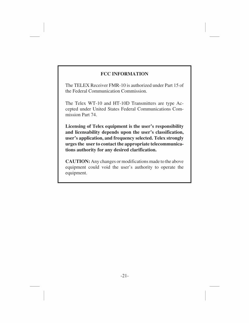
FCC INFORMATION
The TELEX Receiver FMR-10 is authorized under Part 15 ofthe Federal Communication Commission.
The Telex WT-10 and HT-10D Transmitters are type Ac-cepted under United States Federal Communications Com-mission Part 74.
Licensing of Telex equipment is the user’s responsibilityand licensability depends upon the user’s classification,user’s application, and frequency selected. Telex stronglyurges the user to contact the appropriate telecommunica-tions authority for any desired clarification.
CAUTION: Any changes or modifications made to the aboveequipment could void the user’s authority to operate theequipment.

ACCESSORIES AND REPLACEMENT PARTS
Order No. Description
450131 Plastic belt clip for bodypack63850006 WLM-50 tie clip-horizontal63850007 WLM-50 tie clip-vertical64277000 WLM-50 omnidirectional lapel microphone57013001 WLM-50 foam windscreen
70925001 ELM-22 MicroMini™ omnidirectional lapel mic70928001 ELM-22 mic clip57013001 ELM-22 foam windscreen450124 Spring-adjusted handheld mic stand adapter870343 Deluxe handheld mic stand adapter71081001 Rack-mount kit - Single71081002 Rack-mount kit - Double730139 120-volt power supply (US/Canada type)730140 230-volt power supply (EURO type)730103 230-volt power supply (UK type)71253000 UAD-2 Antenna/power distribution system
(supplies 4 units) (600-780 MHz)
879010 1/4-wave antenna with connector (668-746 MHz)71147000 ALP-450 Directional log periodic antenna (450-900 MHz)870658-5 1/2-wave antenna with TNC connector (690-725 MHz)870658-6 1/2-wave antenna with TNC connector (725-760 MHz)71138000 Universal bracket for 1/2-wave antenna with
10 ft. (3.05m) coax cable
71151025 25 ft. (7.62m) coax cable with TNC connectors71151050 50 ft. (15.24m) coax cable with TNC connectors71151075 75 ft. (22.86m) coax cable with TNC connectors71151100 100 ft. (30.48m) coax cable with TNC connectors
-22-


R
PN 803341 May 2001
Telex Communications Inc., 12000 Portland Ave. South, Burnsville, MN 55337(952) 884-4051, (800) 828-6107, Fax: (952) 887-9212


![AudioCom Training rev3 - textfiles.compdf.textfiles.com/manuals/STARINMANUALS/Telex Intercom/Manuals... · 1 Telex Intercom 1]Small System Intercom AudioCom RTS-TW 2] Large System](https://img.pdfslide.us/doc/110x75/5b25fa067f8b9ad4348b517a/audiocom-training-rev3-intercommanuals-1-telex-intercom-1small-system.jpg)