Embed Size (px)
Citation preview

256 PHILIPS TECHNICAL REVIEW VOLUME 26
Television transmitters for the' ultra-high frequency bandJ. A. van der Vorm Lucardie
A number of frequency bands in the very high andultra-high frequency regions of the radio spectrumhave been set aside by international agreement forthe provision of television and sound broadcastingprogrammes. In these regions, which are generallyreferred to by their initials VHF and UHF, a total offive bands are available. Bands I, IJ and III are in theVHF spectrum and bands IVand V in the UHF. Band11 is used for sound broadcasting, while the othershave been assigned to television broadcasting.
For frequency-band allocation the world is di-vided into three regions, and the location' of thefrequency bands varies slightly for each of theseregions. That for Europe, the Near East and NorthAfrica was last defined in 1961 during the Stockholmconference [11. As the use of frequencies in UHFbands IV and V was still in a very early stage, it provedpossible to definethe bandwidth available per televisionchannel - 8Mcfs - and the positions of the visioncarrier frequencies within bands IV and V in a uni-form manner.
For the sake of completeness the positions of thefive bands are here quoted:Band I : 41 - 68 Mcfs (7.3 - 4 m),Band 11: 87.5 - 100 Mcfs (3.4 - 3 m),Band Ill: 162 - 230 Mcfs (1.85 - 1.3 m),Band IV: 470 - 582 Mc/s €64 - 51 cm),Band V : 582 - 960 Mcfs (51 - 31 cm).It will be seen from this table that bands I and IIIare relatively narrow and they can therefore accom-modate only a limited number of TV channels.
The service area of a television transmitter - i.e.the area in which the field strength is sufficient toensure good picture quality - depends on the heightof the aerial and is confined within a radius of ap-proximately 35 miles (60 km) for powerful stations.The interference area, however, extends much furtherand therefore the distance between two transmitterswhich it is intended to operate on the same frequencyhas to be several hundred kilometres. It is consequentlyimpossible, even in countries where there is only onetelevision programme, to obtain a completely closedpattern of service areas, as is desirable in Europe, usingonly channels which are available in bands I and Ill.If this is to be achieved, a number of additional chan-nels in the UHF spectrum are necessary.
Ir. J. A. vall der Vorm Lucardie is 011 the staff of N. V. Philips'"Telecommunicatie Industrie, Hilversum.
621.397.61.029.6
In addition to this need, however, a far greater onehas been created by the desire to transmit a secondor even a third television programme. Fortunately, themuch greater width of bands IV and V amply allowsthe demand to be met in these bands.In designing television transmitters for the UHF
range a number of problems are encountered whichare more or less peculiar to these high frequencies. Weshall devote particular attention to such points in thepresent article.
. The power required for transmitters in bands IV and V
A certain minimum field strength is necessary toensure a good-quality television picture. An increasein the field strength need not involve increasing thetransmitting power but can also be achieved byarranging that the RF power is not radiated uni-formly in all directions but strongly concentrated inthe horizontal plane. A number of aerial designs areavailable for this. It is consequently customary, indescribing television transmitters, to speak of their"effective radiated power", which is defined as theproduct of the power applied to the aerial and a factordependent on the type or design of aerial employed.This factor is expressed in decibels and is called theaerial power gain.When allowance has been made for the effective
aerial height, the gain of the receiving aerial and thenoise contribution of the receiver, it is found that theeffective radiated power of a UHF station has to beapproximately 10dB higher than that of a VHF sta-tion for the same quality of reception. The effectiveradiated power of large stations in bands I and IIIbeing 30-100 kW, an ERP of 300-1000kW is neces-sary in bands IV and V.At the frequencies with which we are concerned
here the limit of the service area more or less coin-cides with the optical horizon as seen from the aerial,which is therefore erected in as elevated a positionas possible. The short wavelengths in bands IV andV make it possible to obtain much greater aerial gainthan in bands I, 11and Ill, while keeping the size ofthe transmitting aerial within economic bounds. Thelimit is determined by mechanical considerations.The maximum gain factor that can be attained isapproximately 50. If, finally, allowance is made for
[1) Final acts of the European VHF/UHF Broadcasting Confer-ence, Stockholm, 1961, published by the International Tele-communication Union, Geneva.
the fact that very considerable losses occur in thecoaxial cable connecting the transmitter and the aerialin its high position at band IV and band V frequencies,it is finally found that transmitter powers of 10-40kWare necessary.On the basis of this result Philips' Telecommunica-
tie Industrie first developed a 10 kW transmitter.This was followed by a 20 kW transmitter, while forsmaller service areas a 2 kW transmitter is now also-available. All of these are suitable for colour television.When necessary, double power can be obtained byconnecting two transmitters in parallel. An advantage
• of this arrangement is that if one transmitter developsa fault, the transmission can continue without inter-ruption, though at reduced power. We shall return tothis point later.
General arrangement of a television transmitter
What is generally called a television transmitter isin fact a combination of two transmitters, one ofwhich transmits the vision signal and the other theaccompanying sound signal. As the aerial and itsfeeder cable form a very costly element, both trans-mitters are always connected to the same aerial bymeans of a coupling network, for which the termcombining unit has been generally adopted in televisionpractice. The combining unit prevents the sound-transmitter and vision-transmitter from interactingon each other.The essential parts of a vision-transmitter are shown
in fig. J. A crystal oscillator A generates a signal whosefrequency is a sub-multiple of the transmitting fre-quency. The transmitting frequency is attained bymultiplication in stage B. In C the radio-frequencysignal is modulated by the video signal, which haspreviously been amplified in the video modulator E.As a rule, modulation takes place as close as possibleto the output stage, and sometimes in the output stageitself. The effect of this is to simplify transmitter tuningand improve the stability. In output stage D the mo-dulated signal is amplified to output level.Amplitude modulation is used for picture trans-
mission. The bandwidthoccupied is limited by sup-pressing. a large part ofthe lower sideband of themodulated signal. In tele-vision transmitters in whichmodulation is effected inthe output stage, the generalpractice is to have the out-put stage followed by a filtercombined with the combi-ning unit. This combination
1965, No. 8/9
..TELEVISION TRANSMITTERS FOR BANDS IV AND V 257
Fig. 1. Diagram showing the main parts of a vision-transmitter.A crystal oscillator; B frequency multipliers; C modulated am-plifier; D final amplifier; E video modulator.
is called a filterplexer. In the transmitter to be describedbelow, a combining unit is adequate since a klystron isused as the final power amplifier. Suppression of thelower sideband is effected with a simple coaxial filterinserted before the final amplifier input.In keeping with normal practice, the sound-trans-
mitter employs frequency modulation. Once again,the process starts with the generation of a signal witha frequency much lower than the transmitting fre-quency. This is done in the oscillator Al (see fig.2),whose frequency is directly modulated with the soundsignal, the latter being amplified in F. Oscillator Alcannot therefore be crystal-controlled and as a resultits stability is limited. If the frequency of Al were tobe raised to its final value solely by multiplication,as is done in the vision-transmitter, the large multipli-cation factor required would result in equally largemagnification of the fluctuations of the mean fre-quency of oscillator Al in relation to its nominal value.The output' frequency from Al is first doubled in VIand then compared with the frequency of a crystaloscillator A2 in circuit C. This comparison circuitdelivers a control voltage which corrects the meanfrequency of Al when deviations are observed. StageV2 triples the output frequency of VI and the outputsignal from V2 is then mixed in stage M with thatfrom a crystal oscillator Aa whose frequency is equalto half the mean transmitting frequency, minus theoutput frequency of Va. The frequency of the outputsignal from M is therefore ---:-after the suppression ofunwanted products of mixing - half the mean trans-
Fig. 2. Diagram showing the main parts of an FM sound-transmitter. Al frequency-mod-ulated oscillator; F sound-amplifier/modulator; Vl doubler; C comparison circuit; A2crystal oscillator; V2 tripler; M mixer circuit; A3 crystal oscillator; V3 doubler; D poweramplifier; E output amplifier. .

258 PHILlPS TECHNICAL REVIEW VOLUME 26
mitting frequency. The transmitting frequency isfinally attained in a doubler Va, which is followed bythe power amplifier D and the output stage E.As we have already observed, the sound-transmitter
operates in the same frequency band as the vision-transmitter, and therefore the design problemsraised by the two are largely the same. There are,however, two problems which are peculiar to thevision-transmitter and owe their origin to the fact thatits power is approximately five times that of the sound-transmitter and that the bandwidth it requires isseveral Mc/s, compared with the few kc/s needed forthe sound-transmitter. In the description which follows,we will therefore confine our observations to the vision-transmitter.At the high frequencies of bands IV and V the
choice of transmitting valves for the output amplifierconstitutes a problem, at least for output powers of10 to 20 kW. We will begin by examining this point.
Transmitting valves for the output stage of the visiontransmitter
In the final amplification stage of their band I andband III transmitters, Philips generally use tetrodesin push-pull connection. At frequencies in the UHFrange, two difficulties arise. In the first place thewavelength at these frequencies is comparable withthe dimensions of the components used. To avoidunwanted radiation and coupling effects which canresult in various types of instability, one must usecoaxial techniques, in which the advantages of thesimple design of the push-pull circuits are lost. Thisalso means, however, that the full transmitting powercan be attained much more simply with one valvethan two.A second feature is that at frequencies in the UHF
range the electron transit time leads to incorrect valveoperation. We shall not analyse this phenomenonhere but merely point out that it greatly reduces theefficiency and power output of tetrodes. The ob-vious remedy for it is to make the electrode spacingas small as possible. There is, however, a limit to thisreduction because, particularly in the case of valvesfor power of 10 kW and more the thermal demandson the material become greater and greater. Thisdrawback can be partly overcome by replacing theglass by a ceramic insulator but even then the limitof what is possible is still reached sooner or later inlarge valves.In the transmitter under discussion use has accor-
dingly been made of klystrons or velocity-modulationtubes. The operating principle of the klystron hasbeen described in numerous publications, includingprevious articles in this journal [2l, and will therefore
not be discussed here. We will merely remind readersthat in this type of valve a beam of electrons is passedthrough a cylindrical chamber which is interrupted bygaps at, basically, two places. If an a.c. voltage isapplied across the first gap that the electron beamtraverses, a velocity modulation of the electrons occurswhich leads to a density modulation of the electronbeam after the electrons have travelled a certaindistance in the valve. If the dimensions of the valveare chosen so that the area where this density.modula-tion is greatest coincides with the location of thesecond gap, energy can be drawn from the electronbeam by loading this gap with a tuned circuit. Ther.f. power thus obtained is many times 'greater thanthat needed to maintain the modulation voltage acrossthe first gap, so that the valve can operate as an ampli-fier.The amplifying effect can be increased further by
arranging a number of gaps one after the other andbridging each gap with a tuned circuit. The Philips11kW klyston type YK 1001, used in the 10 kW trans-mitter, and the 22 kW klystron type YK 1061, usedin the 20 kW transmitter, have four gaps and fourcircuits in the form of resonant cavities, and aresometimes called four-cavity klystrons. For the fre-quencies for which these klystrons are used the gaps areso spaced that both valves are about 5 ft. 6 in. long.Before deciding whether klystrons or normal triodes
or tetrodes are to be preferred for the frequency rangein question, a number of considerations relating todesign, operation and economy must be taken intoaccount. From a design view point the very consider-able power gain of the klystron has the advantagethat the number of power amplifiers which precedeit can be greatly reduced. This means that, despitethe large dimensions of the klystron, the overalldimensions of a klystron transmitter need not begreater than those of a transmitter equipped withtriodes or tetrodes.Operationally, it is of great importance to. be
able to predict impending klystron failure, aswill be seen below. This enables the klystron to bereplaced before it fails, thus eliminating the risk offailure during a broadcast and consequent interruptionof the programme. The fact that it takes much moretime to replace a klystron than the much smallertriodes and tetrodes is, by comparison, of secondaryimportance. There is often no means of predictingthe end of the life of the latter type of valves with anycertainty and the possibility of their failure during abroadcast cannot be disregarded. In view of the pre-
[2] See, for example, B. B. van Iperen, Velocity-modulationvalves for 100 to 1000 watts continuous output, Philips
• tech. Rev. 13, 209-222, 1951/52.

1965, No. 8/9 TELEVISION TRANSMITTERS FOR BANDS IV AND V 259
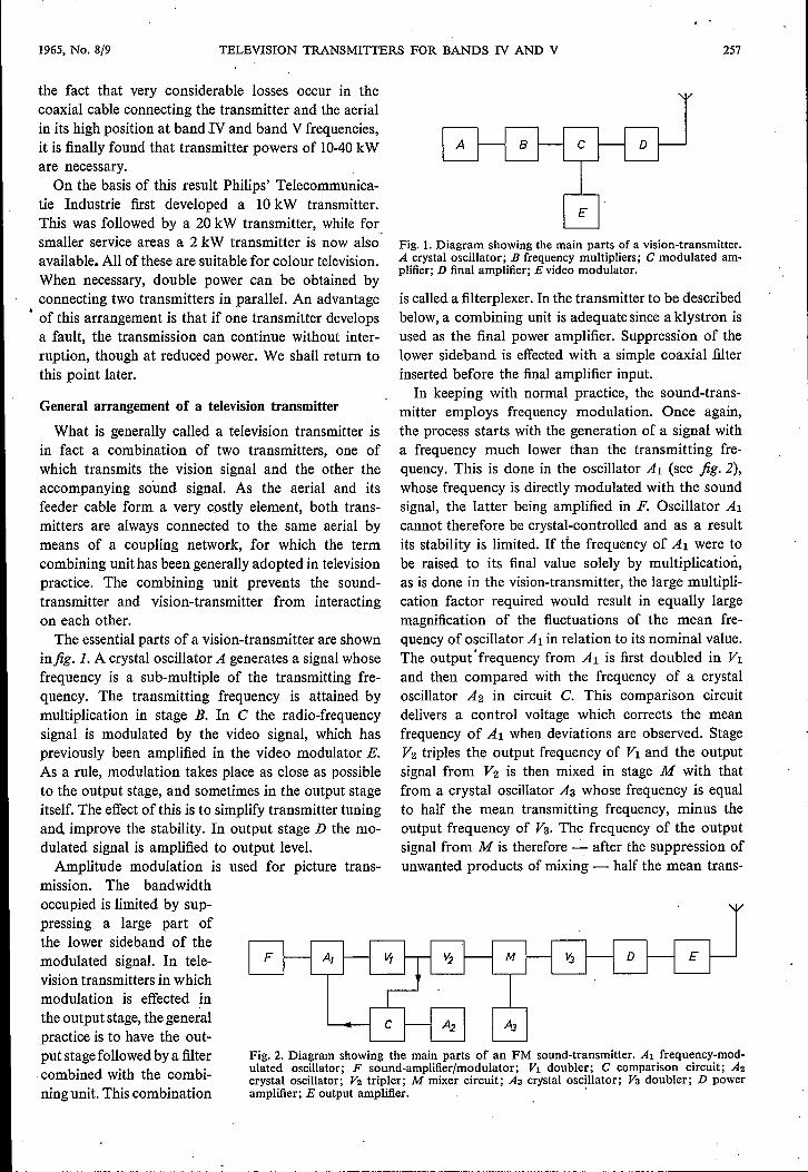
Fig. 3. Photograph of the type YK 100.1,four-cavity klystron without focusing magnets orresonant cavities. The getter ion-pump is visible at the top of the valve.
Fig. 4. Arrangement of a type YK 1001 klystron in the output stage of the 10 kW vision-transmitter.
.---------------;-;~------------------------------------- -------
260 , PHILIPS TECHNICAL REVIEW VOLUME 26
sent trend towards television stations which are notpermanently attended, the time involved in travellingto and from the transmitting station is of far moreconsequence than the time required to change the valves.It is therefore preferable that such changes should bemade in the course of routine maintenance visits.The fact that klystrons have a much longer life than
tetrodes economically outweighs the lower purchaseprice of tetrodes. With regard to the power consump-tion of a klystron transmitter, the efficiency of a kly-stron operated as a class A' amplifier can be consider-ably improved by appropriate measures, which willbe discussed in greater detail below. This and the factthat the total number of amplification stages can besmaller in a klystron transmitter mean that the overallefficiency of a klystron transmitter is not inferior tothat of a transmitter equipped with tetrodes, althoughthe tetrodes th-emselves,being connected as class B orclass C amplifiers, are themselves more efficient thanthe klystron.As already observed, a large part of the lower side-
band of the amplitude-modulated vision-transmittercarrier has to be suppressed. It is an advantage ofthe four-cavity klystron that the gain of the valvecan be made markedly selective - a point to whichwe will return - so that the filter inserted in the cir-cuit prior to the modulated stage can be simplifiedstill further.Thus, although from the point of view of design
and economy the advantages of klystrons approxima-tely balance those of triodes and tetrodes, the relia-bility of the klystron transmitter seems to tip the ba-lance in its favour, and it was this consideration whichdetermined the principle adopted in the Philips 10 kWand 20 kW transmitters.
The type YK 1001 klystronAs the design principles embodied in the construc-
tion of the type YK 1001 11 kW and type YK 106122 kW klystrons .are very similar and the klystronshave practically identical dimensions, it will sufficehere to describe a number of details of the YK 1001.Fig. 3 shows this valve without the accessories that
are visible infig. 4, which is a photograph of the samevalve arranged in position in the output stage of the10kW transmitter. The valve is best described withreference to fig.5, which combines a diagram of asection through the klystron with the circuit in whichthe various components of the valve are included.The electron beam traversing the entire valve in the
longitudinal direction is provided by an impregnatedcathode [3l. The life of this very ruggedly constructedtype of cathode is favourably influenced here by thefact that the cathode is clear of the regions in
which high-frequency alternating fields occur, and thisenables the cathode to be given ample dimensions.
The cathode has a concave emitting surface, sothat the electrons emerging from it are already beamedto some extent; the focusing electrode which theelectrons now pass and which has a negative potentialof about 300 V relative to the cathode, ensures that theelectrons are sharply beamed before they enter thevalve proper. Before this happens they also pass anaccelerating anode which, like the walls of the valve,is at earth potential. As the cathode is maintained atapproximately -18 kV, the electrons enter the driftspace at full velocity.On leaving the transit region, the electrons encounter
the collector. As will be seen from the diagram, thelatter has a voltage of about -5 kV relative to thewall of the drift space region. The result is that theelectrons, on leaving the last section of the drift space,are decelerated and arrive ar the collector with reducedvelocity. In this way a portion of the energy impartedto the electrons during their acceleration is recoveredand the efficiency is improved.When the depth of modulation is large, some elec-
trons will already have a low velocity on leaving thedrift space. To prevent these electrons from goingonly part of the way to the collector and returning tothe last section ofthe drift space, the collector is shapedso as to impede these returns as much as possible.Although the electrons, on entering the drift space,
are concentrated by the operation of the focusingelectrode, the beam will tend to disperse again owingto the repelling effect of the electrons on each other.The length of the drift space in relation to its widthis so large that if no countermeasures were taken someof the electrons would strike the wall of the drift space,eventually causing excessive heating of the klystron wall.It is therefore necessary to maintain a focusing effectalong the entire length of the beam. The most econo-mical means of doing this is by using an axial magneticfield. As the beaming effect is independent of the dir-.eetion of the field, so long as the latter is axial, it ispermissible to use either a field which has a fixed dir-ection over the length of the klystron or a field thatreverses its direction several times along the axis ofthe valve.In the earliest klystrons to appear on the market a
field of constant direction was employed which wasgenerated by a number of circular coils surroundingthe klystron. As will be seen in fig. 4, such coils do notfigure in the YK 1001 klystron. They have been re-placed by a number of permanent magnets made offerroxdure. It can be shown [4l that by employing analternating field (i.e. alternating in space but not intime) which is generated by a number of small, per-

1965, No. 8/9 . TELEVISION TRANSMITTERS FOR BANDS IV AND V 261
F
Fig. 5. Combined cross-sectional drawing of the type YK 1001klystron and diagram of the circuit in which it is used. A ionpump; B cathode; C focusing electrode; D acceleration anode;M; to M5 focusing magnets; Tl to T4 resonant cavities; F powersupply rectifier for the ion pump; G 13 kV HT rectifier; H 5 kVHT rectifier; I RF signal from preceding stage; K output signalto aerial.
manent magnets, it is possible to save considerably onmagnetic material compared with an arrangementwhereby a field of fixed orientation is set up with asingle large magnet. The use of permanent magnetsalso means a saving in weight by comparison with theuse of magnetic coils. Of even more importance, how-ever, is the fact that the klystron, being no longersurrounded by coils is freely accessible.The beaming effect obtainable with a magnetic
field of alternating direction does not manifest itselfuntil a certain minimum value of the beam voltage [4]
is reached. The cathode voltage is therefore broughtto its full value at once and then the beam current isincreased by means of the accelerating anode. Whenthe HT rectifier is switched on, the voltage control ofthe accelerating anode is set so that this anode is atcathode potential. Then the accelerating anode isbrought to earth potential in steps.
Despite the very careful degassing to which trans-mitting valves are always subjected, it is necessary toallow for the possibility that when the klystron isbeing put into service, and to a lesser degree when itis in actual operation, residual gas may be releasedfrom various components. The presence of smallamounts of gas has a harmful effect on the life of thecathode and on the operation of the valve as a whole.The klystron therefore has a permanently fitted getterion pump. As fig. 3 shows, this pump is a small cube-shaped box mounted at the top of the tube. It also
serves as a vacuum gauge, operating on the principleindicated by Penning [5], with which the vacuum canbe measured not only before the valve is put into ser-vice but also while it is in operation. The formerpossibility is important because klystrons have a lifeof many thousands of hours and consequently thespare valves which have to be kept in reserve at everytransmitter are sometimes held in store for a long timebefore they go into use. A very tiny leak which cannotbe detected during manufacture may have reduced thevacuum considerably during that period, without byany means having rendered the valve unsuitable foruse, because the ion pump can easily extract the smallquantity of gas that has entered. If any deteriorationis measured, the pump is switched on for a time beforethe valve is put into operation.Regular measurement of the vacuum during opera-
tion gives a check on the condition of the valve, thusmaking it possible to ensure that the valve does notfail at an undesirable moment, e.g. while the transmit-ter is on the air. This, and the regular check on thecondition of the cathode provided by measurement ofthe beam current, make it practically certain that abroadcast need never be interrupted by the failure ofa klystron.
Tuning the output stageIt will be seen from fig. 3 that to maintain the
vacuum, the modulation gaps in the valve are bridgedby ceramic sleeves. As these sleeves are in the r.f.alternating field, the materialof which they are mademust satisfy very stringent requirements. The materialchosen is an aluminium oxide ceramic. .These sleeves are not visible in fig. 4, being enclosed
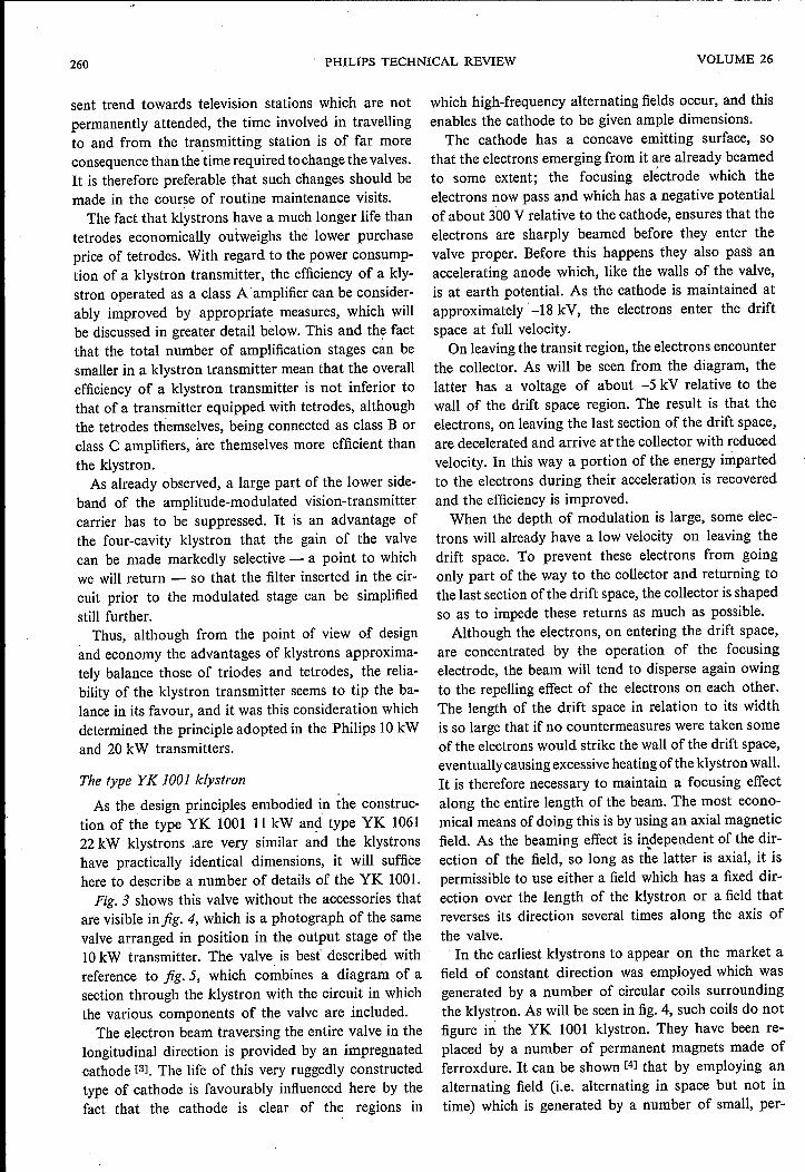
in the resonant cavities bridging the modulation gaps.Each of these cavities takes the form of a rectangularbox fitted round the tube in two halves. One such halfis shown in fig. 6. As can be seen from the photograph,one of the walls of the box is adjustable and thus canbe used to tune the cavity to the desired frequency.The photograph also shows an' adjustable couplingloop. A loop of this kind is used in the first resonantcavity (Tl in fig. 5) to inject the RF power excitationneeded. In cavities T2 and T3 the loop is used to couplean externalload resistance to the RF field. Adjustmentof the coupling loops and tuning of the resonant cav-ities together give the desired form of tuning charac-
(3] R. Levi, Dispenser cathodes, Ill. The impregnated cathode,Philips tech. Rev. 19, 186-190, 1957/58.
(4] J. T. Mendel, C. F. Quate and W. H. Yocom, Electron beamfocusing with periodic permanent magnet fields, Proc. IRE42, 800-810, 1954.
(5] F. M. Penning and K. Nienhuis, Construction and applica-tions of a new design of the Philips vacuum gauge, Philips tech.Rev. 11, 116-122,1949/50, and A. Klopfer and W. Ermrich,Asmall getter ion-pump, Philips tech. Rev. 22, 260-265,1960/61,
262 PHILIPS TECHNICAL REVIEW VOLUME 26
teristic. The coupling loop in the last cavity, T4, isused to take the RF power from the klystron.It can be seen infig. 7 that the resonance frequencies
of the various cavities do not coincide with the car-
Fig. 6. One half of a box-shaped resonant cavity. One wall canbe adjusted to tune the cavity. An adjustable coupling loop canbe used to inject or extract RF power.
~I ----o
-2 -I 0 +1 +2 +] +4 +5 +6 Mc/s_Llf
t t t t1274 Ti Ti
Fig. 7. The resonant cavities are tuned so that the maxima ofthe amplitude-frequency response curves for the various reso-nators are slightly to the side of the nominal carrier frequency.The overall gain characteristic of the klystron is therefore asshown at the bottom of the figure.
rier frequency. The flatness of the resonance curves ofcavities Tl, T2 and T3 can be modified by increasingor decreasing the resistive load on the cavities by meansof the coupling loops. The flatness of the curve ofcavity T4 is of course determined by the aerial load.The result of connecting in tandem the four circuitstuned in this way is shown at the bottom of fig. 7.
The range of frequencies over which the resonantcavities can be tuned extends from 470 to 790 Mc/s.The same klystron can also be used for the band Vtop frequencies, up to 960 Mc/s, but a second set ofresonant cavities is then necessary.
Tj
The driver stages
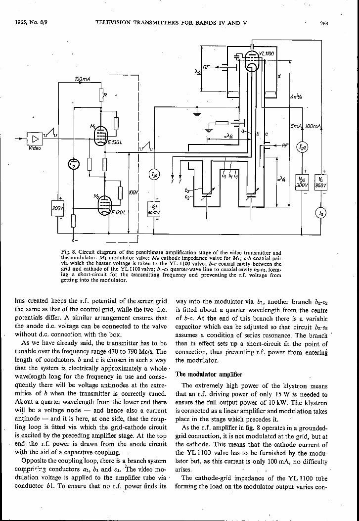
Our discussion of the driver stages will be restrictedto the stage immediately preceding the klystron - i.e.where modulation takes place - and to the modulationamplifier. The penultimate stage of the transmitter isdriven by a signal at carrier frequency. The amplifiervalve used in it is the type YL 1100 tetrode. The cir-cuit of which this valve forms part is reproduced infig· 8, which also shows part of the physical construe-tion. The modulator circuit can also be seen in thediagram.
To increase the stability of the amplifier thegrounded-grid circuit has been chosen, with a tunedcircuit inserted between grid and cathode and anotherbetween the grid and anode. The grid has a d.c. con-nection to earth. Both tuned circuits, as fig. 8 showsconsist entirely of concentric conductors.
Conductors a and b form a coaxial system throughwhich the filament voltage is connected to the valve.The space inside conductor b is therefore free of RFfields. Conductors band c together constitute thegrid-cathode circuit. At the top, the grid-cathode capa-city terminates the coaxial line formed by band c. Avariable capacitor at the other end of this coaxialline is used to adjust the grid-cathode voltage to amaximum.
Cylindrical can d forms a cup over the top of con-ductor c: the space between the two forms the grid-anode circuit, which is tuned with a piston fitted inthe lower part of the box d. The cover top of can dis removable, so that the valve is accessible for re-placement. All connections to the electrodes of thevalve are made by means of circular arrangements ofspring contacts and replacement is therefore a simpleoperation.
The banks of spring contacts for both the screen-grid, anode, and control-grid connections are mountedon flat metal rings. The ring for the control grid con-tacts is fixed to the top of conductor c. This ring andthe one for the screen-grid contacts, which is fitted ontop of it, are separated by a mica ring. The capacitance
1965, No. 8/9 TELEVISION TRANSMITTERS FOR BANDS IV AND V
100mA --I,.J
I,i,iAI
Video
+
263
4x%
5mA 100mA
f
+
---_jFig. 8. Circuit diagram of the penultimate amplification stage of the video transmitter andthe modulator. MI modulator valve; M2 cathode impedance valve for MI; a-b coaxial pairvia which the heater voltage is taken to the YL 1100 valve; b-c coaxial cavity between thegrid and cathode of the YL 1100 valve; bi-ei quarter-wave line to coaxial cavity bz-cz, form-ing a short-circuit for the transmitting frequency and preventing the r.f. voltage fromgetting into the modulator.
hus created keeps the r.f. potentialof the screen gridthe same as that of the control grid, while the two d.c.potentials differ. A similar arrangement ensures thatthe anode d.c. voltage can be connected to the valvewithout d.c. connection with the box.As we have already said, the transmitter has to be
tunable over the frequency range 470 to 790Mc/s. Thelength of conductors band C is chosen in such a waythat the system is electrically approximately a whole .wavelength long for the frequency in use and conse-quently there will be voltage antinodes at the extre-mities of b when the transmitter is correctly tuned.About a quarter wavelength from the lower end therewill be a voltage node - and hence also a currentantinode - and it is here, at one side, that the coup-ling loop is fitted via which the grid-cathode circuitis excited by the preceding amplifier stage. At the topend the r.f. power is drawn from the anode circuitwith the aid of a capacitive coupling.
Opposite the coupling 'loop, there is a,branch systemco:r;npri~::-.5conductors al, bi and Cl. The video mo-dulation voltage is applied to the amplifier tube via .conductor bI. To ensure that. no r.f. power finds its
way into the modulator via bi, another branch b2-C2
is fitted about a quarter wavelength from the centreof b-c. At the end of this branch there 'is a variablecapacitor which can be adjusted so that circuit b2-C2
assumes a condition of series resonance. The branch .then in effect sets up a short-circuit àt the point ofconnection, thus preventing r.f. power from enteringthe modulator.
The modulator amplifier
The extremely high power of the klystron meansthat an r.f. driving power of only 15W is needed toensure the full output power of 10kW. The klystronis connected as a linear amplifier and modulation takesplace in the stage which precedes it.As the r .f. amplifier in fig. 8 operates in a grounded-
grid connection, it is not modulated at the grid, but atthe cathode. This means that the cathode current ofthe YL 1100 valve has to be furnished by the modu-lator but, as this current is only 100mA, no difficultyarises.The cathode-grid impedance of the YL 1100 tube
forming the load on the modulator output varies con-

264 PHILIPS TECHNICAL REVIEW VOLUME 26
siderably with the amplitude of the modulation vol-tage. To reduce this effect the grid-cathode circuit isloaded by a external fixed resistor which is capacitivelycoupled to conductor b. Nevertheless, the output im-pedance of the modulator still varies too much tomake special measures unnecessary. These measuresare designed to reduce the internal resistance of themodulator as far as possible, for only then can asufficiently linear amplitude response be obtainedwith variable load.
As can be seen from fig. 8, modulator tube M!, forwhich a type E 130 L pentode has been, chosen, isconnected as a cathode follower. The anode impe-dance of valve Mz - also an E 130L - whose gridis coupled to the anode of M!, acts as a cathode re-sistance. Careful design of this negative feedback.circuit enabled the internal resistance of the modu-lator to be reduced to a very low value, measurementshowing it to be less than 4 ohms.
Sideband suppression
The video signal has a bandwidth of approximately5Mc/s. The amplitude modulation of the vision-transmitter produces two sidebands, one on eitherside of the carrier frequency, so that a total bandwidthof 10Mc/s is occupied. It has been agreed interna-tionally to suppress a large part of the lower sidebandto save space in the frequency spectrum. In bands Iand 1I, where 7 Mc/s is available per channel, thissideband is cut off in accordance with the curve shownschematically in fig. 9. The curve is flat to 0.75 Mc/sbelow the carrier frequency and reaches zero at apoint 1.25Mc/s below it.The curve shown in fig. la has been adopted as a
standard for the r.f. amplitude response of televisionreceivers. If an r.f. signal is detected whose lowersideband has been suppressed in accordance withfig. 9, the amplitude response of the video signalobtained is flat, except for a 0.5 dB deviation at afrequency of 0.75 Mc/s. This distortion, which isvisible at 0.75 Mc/s in a normal picture, has beenaccepted as unavoidable in bands I and Ill. Neverthe-less, it can be avoided if, as in fig. 11, the transmitterresponse is not allowed to drop until the frequency is1Mc/s below the carrier. This solution is a possibility inbands IV and V, because of the extra space available.Partial suppression of the lower sideband introduces
phase errors into the video signal, and the steeper theslope of the transmitter response c,urve, the greaterthese errors will be. Phase errors are also present inthe receiver. For economic reasons these are correctedin the transmitter. The phase correction usually isessentially a pre-distortion of the video signal. Whensudden level variations take place in the video signal,
-0.5 0.5 1,5Mc;S
Fig. 9. The lower-frequency end of the amplitude-frequencyresponse curve of the vision-transmitter, shown diagrammatic-ally. The response is fiat to 0.75 Mcfs below the transmittingfrequency fz, falling to zero at 1.25 Mcfs below fz.
-1,5 1,5Mc/s
Fig. 10. The amplitude response curve of the average televisionreceiver. It begins to drop 1 Mcfs above the transmitting fre-quency fz and reaches the zero line 1 Mcfs below it.
-0.5 0,5 1,5MC/SFig. 11. The Philips vision-transmitter can be tuned so thatthe residual sideband characteristic of the transmitter assumesthe form seen here. In combination 'with the receiver characte-ristic shown in fig. 10 it gives an overall response which is en-tirely fiat.
pre-distortion causes this signal to "overshoot", i.e.there is for a moment a larger variation in.level thanthat warranted by the actual signal. This means thata sudden change from white to black caus~s temporaryovermodulation of the transmitter. As.....a. bandwidthof 8 Mc/s is available in bands IV and V, the responsecurve can be given a gentler slope in these bands, so

1965, No. 8/9 TELEVISION TRANSMITTERS FOR BANDS IV AND V 265
Fig. 12. The component partsof the Nyquist receiver aremounted on a frame. In front,the Nyquist filter; behind it, thenotch filter; in between, the de-tector, and, on the right, thephase correction filter.
to a crystal detector via apair of filters which will bedescribed below. Thisarrangement not only en-ables the number of electri-cal components to be keptdown, but it also obviatesthe use of amplifier valveswhich, as theyage, becomean important contributorycause of response curvedrift in receivers.
The signal to be mOTIl-tored passes through a high-pass filter, a band-rejectionfilter, a detector and aphase-correction filter, inthat order. The first twofilters determine the am-plitude-frequency responseof the receiver and musttherefore satisfy high stan-dards of stability. Theyare composed of coaxialelements which, to eliminatethe effect of temperaturevariations on the characte-ristics, are made partly ofInvar. Both filters are ac-curately adjusted for the
transmitter frequency chosen and must therefore bereplaced if this frequency is changed.
The first filter, which is used to give the amplitude-frequency response curve the lower-end slope shown infig. 10, is a high-pass filter generally referred to as theNyquist filter. The second is a band-rejection filterfor preventing the sound transmitter signal, which,of course, is also present in the transmitter outputlead, from entering the receiver. This type of filter isknown in television engineering as a notch filter. Thetwo filters are mounted on a chassis together with thecrystal detector and phase correction filter, as shownin jig. 12.
In both the Nyquist filter and the notch filter ther.f. signal is fed in via a coaxial line which has shuntcoaxial stubs at quarter-wavelength intervals. Thesestubs are clearly visible in fig. 12. A cross-section of
that the phase distortion is decreased and less phasecorrection is needed. The bands IV and V transmitterdescribed here can be adjusted to give a residual-side-band response like that shown in fig. 11.
Monitoring the transmitted picture signal
For adjustment of the transmitter and regularsupervision of the transmitted vision signal it isnecessary to have a monitoring receiver with an amp-litude response which is exactly as shown in fig. 10.As this response curve was first indicated by Nyquist,this receiver is generally referred to as a Nyquist demo-dulator. Because of the important task this receiverperforms, its response curve must not vary. As theinput signal to the receiver can be taken straight fromthe transmitter output, sufficient power is availablefor the signal to be applied without pre-amplification
"",
266 PHILlPS TECHNICAL REVmW VOLUME 26
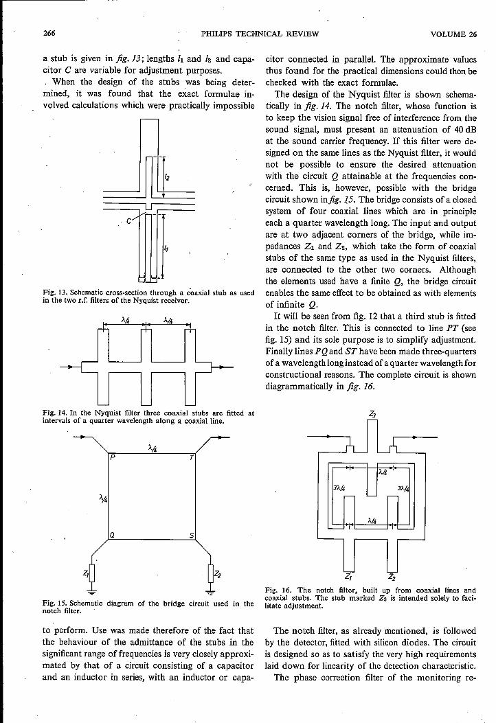
a stub is given in jig. 13; lengths hand /2 and capa-citor C are variable for adjustment purposes.. When the design of the stubs was being deter-mined, it was found that the exact formulae in-volved calculations which were practically impossible
c
I,
Fig. 13. Schematic cross-section through a coaxial stub as usedin the two r.f. filters of the Nyquist receiver.
Fig. 14. In the Nyquist filter three coaxial stubs are fitted atintervals of a quarter wavelength along a coaxial line.
p
Q 5
Fig. IS. Schematic diagram of the bridge circuit used in thenotch filter.
to perform. Use was made therefore of the fact thatthe behaviour of the admittance of the stubs in thesignificant range of frequencies is very closely approxi-mated by that of a circuit consisting of a capacitorand an inductor in series, with an inductor or capa-
citor connected in parallel. The approximate valuesthus found for the practical dimensions could then bechecked with the exact formulae.The design of the Nyquist filter is shown schema-
tically in jig. 14. The notch filter, whose function isto keep the vision signal free of interference from thesound signal, must present an attenuation of 40 dBat the sound carrier frequency. If this filter were de-signed on the same lines as the Nyquist :filter, it wouldnot be possible to ensure the desired attenuationwith the circuit Q attainable at the frequencies con-cerned. This is, however, possible with the bridgecircuit shown infig. ]5. The bridge consists of a closedsystem of four coaxial lines which are in principleeach a quarter wavelength long. The input and outputare at two adjacent corners of the bridge, while im-pedances Z1 and Z2, which take the form of coaxialstubs of the same type as used in the Nyquist filters,are connected to the other two corners. Althoughthe elements used have a finite Q, the bridge circuitenables the same effect to be obtained as with elementsof infinite Q.It will be seen from fig. 12 that a third stub is fitted
in the notch filter. This is connected to line PT (seefig. 15) and its sole purpose is to simplify adjustment.Finally lines PQ and ST have been made three-quartersof a wavelength long instead of a quarter wavelength forconstructional reasons. The complete circuit is showndiagrammatically in jig. 16.
À.4
3),./4 3À/4r+' '-- -
À/I,-I ., '---
Z, Z2
Fig. 16. The notch filter, built up from coaxial lines andcoaxial stubs. The stub marked Z3 is intended solely to faci-litate adjustment.
The notch filter, as already mentioned, is followedby the detector, fitted with silicon diodes. The circuitis designed so as to satisfy the very high requirementslaid down for linearity of the detection characteristic.The phase correction :filter of the monitoring re-

1965, No. 8/9 TELEVISION TRANSMITTERS FOR BANDS IV AND V 267
ceiver is composed of a number of bridged-T sec-tions. The properties of this filter are best representedby the "group delay" characteristic, as this is mostsuitable for practical measurement. The filter is nor-mally given the characteristic shown in jig. 17 but ifdesired a filter with a different characteristic can besupplied.
Fig. 17. Group delay characteristic for normal setting of thephase-correction filter in the Nyquist demodulator.
Paralleling transmitters
In the interest of continuity of television broadcasts,special measures are taken to avoid interruptions. Forexample, equipment can be duplicated. For economicreasons and to be certain that stand-by equipmentwill not fail at the very moment its services are needed,it is desirable to keep this equipment in operation. Agood solution to the problem is, having decided uponthe operating power of the transmitter, to have thispower provided by two transmitter units, each of halfthe power and operating in parallel. If one of the unitsfails the transmission wil! go on without interruption,although at reduced power.
When two transmitters are connected in parallel inthis way, it can be assumed that their frequencies aredetermined by a common crystal oscillator, and thattheir phase relationship is therefore permanentlyfixed. Two courses are then available. The first possi-bility is to feed both output signals to a bridge circuitfor combination. The composite signal then goes fromthe bridge circuit to the aerial via the common aerialfeeder. The drawback of this arrangement is that a
broadcast can stil! be interrupted by a fault in thebridge circuit, the feeder or the aerial. If it is desiredto eliminate even that possibility, the aerial can bedivided into two identical parts and the two transmit-ters connected to these half aerials by separate feeders.No bridge circuit is then needed and the signals com-bine after radiation from the aerials.
Although the second arrangement reduces thechance of interruptions during broadcasts to a mini-mum, it was found, when Philips TelecommunicatieIndustrie set up a transmitter operating on this prin-ciple, that certain precautions have to be taken inbuilding and tuning the two halves of the aerial ifunwanted side effects are to be avoided.
These side effects are due to the fact that in additionto the main lobe, whose axis generally slopes slightlydownwards towards the horizon, the radiation patternalso comprises a number of side lobes. The minimabetween the various lobes are due to the fact that thesignals of the two aerial halves in the direction ofthese minima are practically cancelled out by interfer-ence. In the case of a clear-cut minimum, whencancellation is practically complete, the residual com-ponent of the signal will depend very closelyon thephase relation between the two signals radiated bythe two half-aerials. As this phase relation also dependson the momentary frequency determined by the mod-ulation, the picture quality may be very unfavourablyaffected, and negative pictures may even occur, inareas situated in the direction of radiation patternminima. It will be obvious from what has been saidthat this drawback can be overcome by designing andadjusting the aerial so that no very pronounced minimaoccur.
Summary. The article describes a number of problems confront-ing the designer of television transmitters for ultra-high fre-quencies (470-960 Mc/s), When allowance is made for propaga-tion conditions at these frequencies and the gain that can beattained with the aid of the directional effect of the transmittingaerial, transmitter outputs of 10-40 kW are found to be neces-sary. These outputs and the frequencies used bring designersto the limit of what is possible with triodes and tetrodes. Twotypes of transmitter built by Philips for these bands thereforeemploy klystrons. A description of the 10 kW four-cavity klys-tron type YK 1001 is followed by a description of the outputstage tuning procedure. The four resonant cavities can be tunedin such a way that the conventional sideband suppression filteris made largely superfluous. The penultimate stage of the vision-transmitter employs a tetrode in grounded-grid connection anduses coaxial techniques throughout. The cathode current forthis stage is supplied by the modulator, which has a very lowinternal resistance. The receiver used to monitor the qualityof the transmitted signal has to possess extremely constantcharacteristics and is therefore of special design. The filtersincorporated in it are composed of coaxial elements madepartly of Invar. Finally the article points out possible sourcesof degradation in picture quality when transmitters are con-nected in parallel.