Embed Size (px)
Citation preview
Copy
613-0
TELESYN® SeriesServices Guide
Issue 1Release 8.0
00761 Rev.A 070328
right © 2007 Allied Telesis Holdings K.K. All rights reserved. Information subject to change without notice.
IntroductionCongratulations on your purchase of a Telesyn™ product. This product is part of a family of products that leverages Ethernet switching technology to offer service providers a range of services, including data (low and high speed) video, and voice.
Who Should Read This Guide?Service provider staff who are involved with the implementation of data, video, and voice services. This document provides an outline for the engineering and provisioning of these services using the various technologies (ADSL, SHDSL, etc.) available with the Telesyn product.
About this GuideThis guide includes:
• Section 1 provides an outline of the document and shows the user how to access necessary information and procedures.
• Section 2 shows how data services are provided (such as by SHDSL), and the important network, hardware, and software considerations to take into account.
• Section 3 shows how video data are provided (such as by ADSL), and the important network, hardware, and software considerations to take into account
• Section 4 shows how voice services are provided (such as by the POTS24 card), and the important network, hardware, and software considerations to take into account
• Section 5 describes Circuit Emulation Service (CES), which provides DS1/E1-based services to subscribers while shifting to a packet-based infrastructure for the rest of the network.
• Section 6 describes Ethernet Passive Optical Network (EPON) and traffic considerations.
• Section 7 explains any special configurations and how they can be incorporated into the provider’s network.
• Section 8 shows some sample configurations that optimally combine the services described in the previous sections. The sample configurations include provisioning at the network level (such as Protection Switching).
© 2007 Allied Telesis Holdings K.K. All rights reserved. Information subject to change without notice.
Table of Contents
1 What this Guide Provides- - - - - - - - - - - - - - - - - - - - - - - - -1-11.1 Overview- - - - - - - - - - - - - - - - - - - - - - - - - - - - - - - - - - - - - - - - - - - - - - - - - - - - - - - - 1-1
1.2 How this Document is Organized- - - - - - - - - - - - - - - - - - - - - - - - - - - - - - - - - - - - - - - 1-11.2.1 Definition of Terms - - - - - - - - - - - - - - - - - - - - - - - - - - - - - - - - - - - - - - - - - - - - 1-11.2.2 Document Sections- - - - - - - - - - - - - - - - - - - - - - - - - - - - - - - - - - - - - - - - - - - - - 1-21.2.3 Final Section (Provisioning Example) - - - - - - - - - - - - - - - - - - - - - - - - - - - - - - - - 1-3
2 Optimizing Data Services (SHDSL) - - - - - - - - - - - - - - - - - -2-12.1 Overview- - - - - - - - - - - - - - - - - - - - - - - - - - - - - - - - - - - - - - - - - - - - - - - - - - - - - - - - 2-1
2.2 Technology Implementation - - - - - - - - - - - - - - - - - - - - - - - - - - - - - - - - - - - - - - - - - - 2-32.2.1 Standards - - - - - - - - - - - - - - - - - - - - - - - - - - - - - - - - - - - - - - - - - - - - - - - - - - - 2-32.2.2 Telesyn Implementation - - - - - - - - - - - - - - - - - - - - - - - - - - - - - - - - - - - - - - - - - 2-3
2.3 Features - - - - - - - - - - - - - - - - - - - - - - - - - - - - - - - - - - - - - - - - - - - - - - - - - - - - - - - - 2-4
2.4 Hardware Provisioning- - - - - - - - - - - - - - - - - - - - - - - - - - - - - - - - - - - - - - - - - - - - - - 2-52.4.1 Port Numbering - - - - - - - - - - - - - - - - - - - - - - - - - - - - - - - - - - - - - - - - - - - - - - - 2-52.4.2 CPE Devices - - - - - - - - - - - - - - - - - - - - - - - - - - - - - - - - - - - - - - - - - - - - - - - - - 2-5
2.5 Software Engineering - - - - - - - - - - - - - - - - - - - - - - - - - - - - - - - - - - - - - - - - - - - - - - - 2-62.5.1 Interface Association - - - - - - - - - - - - - - - - - - - - - - - - - - - - - - - - - - - - - - - - - - - 2-62.5.2 Conversion from Normal to Bonded SHDSL - - - - - - - - - - - - - - - - - - - - - - - - - - - 2-62.5.3 SHDSL Port Audit - - - - - - - - - - - - - - - - - - - - - - - - - - - - - - - - - - - - - - - - - - - - - 2-72.5.4 SHDSL RMON Statistics - - - - - - - - - - - - - - - - - - - - - - - - - - - - - - - - - - - - - - - - 2-82.5.5 SHDSL PMON - - - - - - - - - - - - - - - - - - - - - - - - - - - - - - - - - - - - - - - - - - - - - - - 2-8
3 Optimizing Video Services - - - - - - - - - - - - - - - - - - - - - - - -3-13.1 Overview- - - - - - - - - - - - - - - - - - - - - - - - - - - - - - - - - - - - - - - - - - - - - - - - - - - - - - - - 3-1
3.2 Video Services provided by ADSL - - - - - - - - - - - - - - - - - - - - - - - - - - - - - - - - - - - - - - 3-13.2.1 Overview - - - - - - - - - - - - - - - - - - - - - - - - - - - - - - - - - - - - - - - - - - - - - - - - - - - 3-13.2.2 Technology - - - - - - - - - - - - - - - - - - - - - - - - - - - - - - - - - - - - - - - - - - - - - - - - - - 3-33.2.3 Features - - - - - - - - - - - - - - - - - - - - - - - - - - - - - - - - - - - - - - - - - - - - - - - - - - - - 3-33.2.4 Network Engineering - - - - - - - - - - - - - - - - - - - - - - - - - - - - - - - - - - - - - - - - - - - 3-53.2.5 Software Engineering - - - - - - - - - - - - - - - - - - - - - - - - - - - - - - - - - - - - - - - - - - 3-10
Telesyn Service Guide (Table of Contents)
3.2.6 Maintenance - - - - - - - - - - - - - - - - - - - - - - - - - - - - - - - - - - - - - - - - - - - - - - - - -3-213.2.7 Loop Length and Data Rates (Rate vs. Reach) for ADSL Modes- - - - - - - - - - - - - -3-23
3.3 Video Services Provided by Fast Ethernet/Fiber - - - - - - - - - - - - - - - - - - - - - - - - - - -3-233.3.1 Overview - - - - - - - - - - - - - - - - - - - - - - - - - - - - - - - - - - - - - - - - - - - - - - - - - - -3-233.3.2 Technology- - - - - - - - - - - - - - - - - - - - - - - - - - - - - - - - - - - - - - - - - - - - - - - - - -3-253.3.3 Features - - - - - - - - - - - - - - - - - - - - - - - - - - - - - - - - - - - - - - - - - - - - - - - - - - - -3-253.3.4 Network Engineering - - - - - - - - - - - - - - - - - - - - - - - - - - - - - - - - - - - - - - - - - - -3-253.3.5 Software Engineering- - - - - - - - - - - - - - - - - - - - - - - - - - - - - - - - - - - - - - - - - - -3-253.3.6 Maintenance - - - - - - - - - - - - - - - - - - - - - - - - - - - - - - - - - - - - - - - - - - - - - - - - -3-34
4 Optimizing Voice Services - - - - - - - - - - - - - - - - - - - - - - - - 4-14.1 Overview - - - - - - - - - - - - - - - - - - - - - - - - - - - - - - - - - - - - - - - - - - - - - - - - - - - - - - - -4-1
4.2 POTS Only with Call Agent (POTS24 Card) - - - - - - - - - - - - - - - - - - - - - - - - - - - - - - -4-14.2.1 Overview - - - - - - - - - - - - - - - - - - - - - - - - - - - - - - - - - - - - - - - - - - - - - - - - - - - -4-14.2.2 Technology- - - - - - - - - - - - - - - - - - - - - - - - - - - - - - - - - - - - - - - - - - - - - - - - - - -4-24.2.3 Features - - - - - - - - - - - - - - - - - - - - - - - - - - - - - - - - - - - - - - - - - - - - - - - - - - - - -4-34.2.4 Network Engineering - - - - - - - - - - - - - - - - - - - - - - - - - - - - - - - - - - - - - - - - - - - -4-44.2.5 Hardware Provisioning- - - - - - - - - - - - - - - - - - - - - - - - - - - - - - - - - - - - - - - - - - -4-54.2.6 Software Engineering- - - - - - - - - - - - - - - - - - - - - - - - - - - - - - - - - - - - - - - - - - - -4-6
4.3 Derived Voice (Residential Gateway) - - - - - - - - - - - - - - - - - - - - - - - - - - - - - - - - - - - -4-74.3.1 Overview - - - - - - - - - - - - - - - - - - - - - - - - - - - - - - - - - - - - - - - - - - - - - - - - - - - -4-74.3.2 Telesyn Implementation - - - - - - - - - - - - - - - - - - - - - - - - - - - - - - - - - - - - - - - - - -4-7
5 Circuit Emulation Service (CES) - - - - - - - - - - - - - - - - - - - 5-15.1 Overview - - - - - - - - - - - - - - - - - - - - - - - - - - - - - - - - - - - - - - - - - - - - - - - - - - - - - - - -5-1
5.2 Technology - - - - - - - - - - - - - - - - - - - - - - - - - - - - - - - - - - - - - - - - - - - - - - - - - - - - - - -5-1
5.3 Features - - - - - - - - - - - - - - - - - - - - - - - - - - - - - - - - - - - - - - - - - - - - - - - - - - - - - - - - -5-1
5.4 Network Engineering- - - - - - - - - - - - - - - - - - - - - - - - - - - - - - - - - - - - - - - - - - - - - - - -5-45.4.1 Packet Network Considerations - - - - - - - - - - - - - - - - - - - - - - - - - - - - - - - - - - - - -5-45.4.2 NUMBYTES and Bandwidth Correlation - - - - - - - - - - - - - - - - - - - - - - - - - - - - - -5-65.4.3 NUMBYTES vs. Minimum / Maximum Jitter Values - - - - - - - - - - - - - - - - - - - - - -5-7
5.5 Software Engineering - - - - - - - - - - - - - - - - - - - - - - - - - - - - - - - - - - - - - - - - - - - - - -5-105.5.1 Statistics - - - - - - - - - - - - - - - - - - - - - - - - - - - - - - - - - - - - - - - - - - - - - - - - - - -5-10
6 Ethernet Passive Optical Network (EPON)- - - - - - - - - - - - - 6-16.1 Overview - - - - - - - - - - - - - - - - - - - - - - - - - - - - - - - - - - - - - - - - - - - - - - - - - - - - - - - -6-1
TOC-2 Telesyn Service Guide (Table of Contents)
6.2 Traffic Management- - - - - - - - - - - - - - - - - - - - - - - - - - - - - - - - - - - - - - - - - - - - - - - - 6-16.2.1 Classifiers - - - - - - - - - - - - - - - - - - - - - - - - - - - - - - - - - - - - - - - - - - - - - - - - - - - 6-16.2.2 QoS (Traffic Queues/Priorities) - - - - - - - - - - - - - - - - - - - - - - - - - - - - - - - - - - - - 6-16.2.3 Connection Admission Control (CAC) - - - - - - - - - - - - - - - - - - - - - - - - - - - - - - - 6-2
6.3 Feature Interaction - - - - - - - - - - - - - - - - - - - - - - - - - - - - - - - - - - - - - - - - - - - - - - - - 6-3
6.4 Technology - - - - - - - - - - - - - - - - - - - - - - - - - - - - - - - - - - - - - - - - - - - - - - - - - - - - - - 6-4
7 Special Network Configurations - - - - - - - - - - - - - - - - - - - -7-17.1 Overview- - - - - - - - - - - - - - - - - - - - - - - - - - - - - - - - - - - - - - - - - - - - - - - - - - - - - - - - 7-1
7.2 FE10 Upstream Interface - - - - - - - - - - - - - - - - - - - - - - - - - - - - - - - - - - - - - - - - - - - - 7-17.2.1 Overview - - - - - - - - - - - - - - - - - - - - - - - - - - - - - - - - - - - - - - - - - - - - - - - - - - - 7-17.2.2 Feature Interaction - - - - - - - - - - - - - - - - - - - - - - - - - - - - - - - - - - - - - - - - - - - - - 7-1
8 Optimizing All Services (Triple Play) - - - - - - - - - - - - - - - - -8-18.1 Overview- - - - - - - - - - - - - - - - - - - - - - - - - - - - - - - - - - - - - - - - - - - - - - - - - - - - - - - - 8-1
8.1.1 Sample Configuration - Network Level - - - - - - - - - - - - - - - - - - - - - - - - - - - - - - - 8-1
8.2 Provisioning Example - Overview - - - - - - - - - - - - - - - - - - - - - - - - - - - - - - - - - - - - - - 8-2
Telesyn Service Guide (Table of Contents) TOC-3

TOC-4 Telesyn Service Guide (Table of Contents)
1. What this Guide Provides
1.1 OverviewThe Telesyn documentation set includes the Telesyn User Guide and Reference Guides. These Guides provide the user an overview of the products that make up the Telesyn product set, the features that are provided for these products, and the parameters, measurements, audits, and logs that are used to activate and use these features.
Starting from the information provided in these Guides, this document is intended to give the user recommenda-tions on how to:
• Engineer the system before physical provisioning• Help configure key parameters and measurements so that services can be provisioned to meet the engineering
requirements• Monitor the systems so that problems (and potential problems) can be more effectively recognized and
resolved.
Note: This document is not intended to give the user a complete overview of all aspects of the Telesyn product; that is provided in the Telesyn User Guide. By reading this Guide, the user can see what features are available and how to optimally use these features.
1.2 How this Document is Organized
1.2.1 Definition of TermsTerms such as services, features, applications, products, technologies, solutions, etc. are often used when describ-ing various products in the network and their capabilities; to help the reader, these terms are explicitly defined here since they help in understanding the organization of this Guide:
• Service - Telesyn products provide what is called Triple Play, and these are the three services that providers wish to make available to their customers: Video, Data, and Voice.
• Technology - The Telesyn products employ the technologies that are suited to provide a service, such as SHDSL for high-speed data. These technologies are based on standards that are both public and Telesyn-spe-cific, and so these standards must be reviewed to ensure the provider knows how Telesyn meets/implements these standards.
• Feature - These are the functions used that allow the technology to meet the various standards. Since these functions can be in a hierarchy, features can be part of a larger Feature Group
1-1 Telesyn Service Guide (What this Guide Provides)
How this Document is Organized Document Sections
This document will focus on the technologies that are used to provide these Services
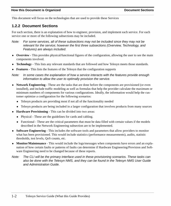
1.2.2 Document SectionsFor each section, there is an explanation of how to engineer, provision, and implement each service. For each service one or more of the following subsections may be included.
Note: For some services, all of these subsections may not be included since they may not be relevant for the service; however the first three subsections (Overview, Technology, and Features) are always included.
• Overview - This provides physical/functional figures of the configuration, allowing the user to see the main components involved.
• Technology - This lists any relevant standards that are followed and how Telesyn meets those standards.• Features - This lists the features of the Telesyn that the configuration supports
Note: In some cases the explanation of how a service interacts with the features provide enough information to allow the user to optimally provision the service.
• Network Engineering - These are the tasks that are done before the components are provisioned (or even installed), and include traffic modeling as well as formulas that help the provider calculate the maximum or minimum numbers of components for various configurations. Ideally, the information would help the cus-tomer optimize a configuration for the following scenarios:• Telesyn products are providing most if not all of the functionality needed• Telesyn products are being included in a larger configuration that involves products from many sources
• Hardware Provisioning - This can be divided into two areas:• Physical - These are the guidelines for cards and cabling.• Functional - These are the critical parameters that must be data filled with certain values if the models
described in the Network Engineering subsection are to be implemented.• Software Engineering - This includes the software tools and parameters that allow providers to monitor
what has been provisioned. This would include statistics (performance measurements), audits, statistic thresholds, test levels, QoS counts, etc.
• Monitor/Maintenance - This would include the logs/messages when components have errors and an expla-nation of how certain faults or patterns of faults can determine if Hardware Engineering/Provision and Soft-ware Engineering need to be changed because of these reports.
Note: The CLI will be the primary interface used in these provisioning scenarios. These tasks can also be done with the Telesyn NMS, and they can be found in the Telesyn NMS User Guide and Administration Guide.
Telesyn Service Guide (What this Guide Provides)1-2
Final Section (Provisioning Example) How this Document is Organized
1.2.3 Final Section (Provisioning Example)The final section of this document provides a complete example that shows a large network that spans several devices, VLANs, and subnetworks, so the user can see how services are combined in real-world scenarios. This helps providers understand how Telesyn products fit into the network and their interactions with other products.
Note: In this Section, the Telesyn NMS will be used in the provisioning scenarios. This will highlight how using the Telesyn NMS allows the provider to provision customers effectively and efficiently using a GUI interface as well as features such as profiles. Moreover, by using the Telesyn NMS, the provider can make network level changes (such as protection switching), easier and less prone to error.
1-3Telesyn Service Guide (What this Guide Provides)

How this Document is Organized Final Section (Provisioning Example)
Telesyn Service Guide (What this Guide Provides)1-4
2. Optimizing Data Services (SHDSL)
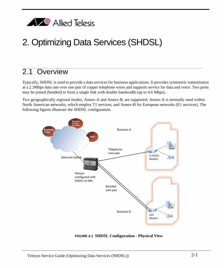
2.1 OverviewTypically, SHDSL is used to provide a data services for business applications. It provides symmetric transmission at a 2.3Mbps data rate over one pair of copper telephone wires and supports service for data and voice. Two ports may be joined (bonded) to form a single link with double bandwidth (up to 4.6 Mbps).
Two geographically regional modes, Annex-A and Annex-B, are supported. Annex-A is normally used within North American networks, which employ T1 services, and Annex-B for European networks (E1 services). The following figures illustrate the SHDSL configuration.
FIGURE 2-1 SHDSL Configuration - Physical View
Telesyn MAPconfigured withSHDSL16 SMs
Telephonewire pair
Bondedwire pair
G.SHDSLModem
Ethernet Uplink
BusinessPTSN
BusinessIP DataServices
VoIP
GSVModem
Business A
Business B
2-1 Telesyn Service Guide (Optimizing Data Services (SHDSL))
Overview
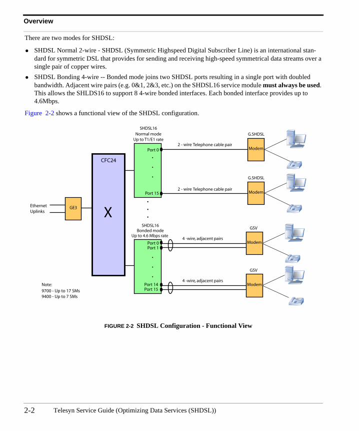
There are two modes for SHDSL:
• SHDSL Normal 2-wire - SHDSL (Symmetric Highspeed Digital Subscriber Line) is an international stan-dard for symmetric DSL that provides for sending and receiving high-speed symmetrical data streams over a single pair of copper wires.
• SHDSL Bonding 4-wire -- Bonded mode joins two SHDSL ports resulting in a single port with doubled bandwidth. Adjacent wire pairs (e.g. 0&1, 2&3, etc.) on the SHDSL16 service module must always be used. This allows the SHLDS16 to support 8 4-wire bonded interfaces. Each bonded interface provides up to 4.6Mbps.
Figure 2-2 shows a functional view of the SHDSL configuration.
FIGURE 2-2 SHDSL Configuration - Functional View
GE3
Modem
SHDSL16
Telephone cable pair
G.SHDSL
Modem
G.SHDSL
Modem
SHDSL16
GSV
Modem4 -wire, adjacent pairs
4 -wire, adjacent pairs
GSV
Normal mode
Bonded mode
Up to T1/E1 rate
Up to 4.6 Mbps rate
CFC24
XEthernetUplinks
Port 0
Port 0Port 1
Port 14Port 15
Port 15
.
.
.
.
.
.
2 - wire
Telephone cable pair2 - wire
.
.
.
9700 - Up to 17 SMs9400 - Up to 7 SMs
Note:
Telesyn Service Guide (Optimizing Data Services (SHDSL))2-2
Standards Technology Implementation
2.2 Technology Implementation
2.2.1 Standards
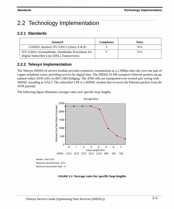
2.2.2 Telesyn ImplementationThe Telesyn SHDSL16 service module provides symmetric transmission at a 2.3Mbps data rate over one pair of copper telephone wires, providing service for digital data. The SHDSL16 SM transports Ethernet packets encap-sulated within ATM cells via RFC1483 bridging. The ATM cells are transported over twisted pair wiring with SHDSL encoding as AAL5. The subscriber CPE is a SHDSL modem that recovers the Ethernet packets from the ATM payload.
The following figure illustrates averages rates over specific loop lengths.
FIGURE 2-3 Average rates for specific loop lengths
Standard Compliance Notes
G.SHDSL Standard, ITU G.991.2 (Annex A & B) Y N/A
ITU G.994.1 (G.handshake, Handshake Procedures for Digital Subscriber Line (DSL) Transceivers)
Y N/A
Loop Length (km)
Att
ain
edLi
ne
Rat
e(k
bp
s)(A
vera
ge)
SHDSL
0
500
1000
1500
2000
2500
0 1 2 3 4 5 6 7
2312 2312 2312 2312 2120 968 520 328-
Average Rates
Modem - Xavi 3102r
Maximum Upstream Rate - 2312
Maximum Downstream Rate - 72
2-3Telesyn Service Guide (Optimizing Data Services (SHDSL))
Features Telesyn Implementation
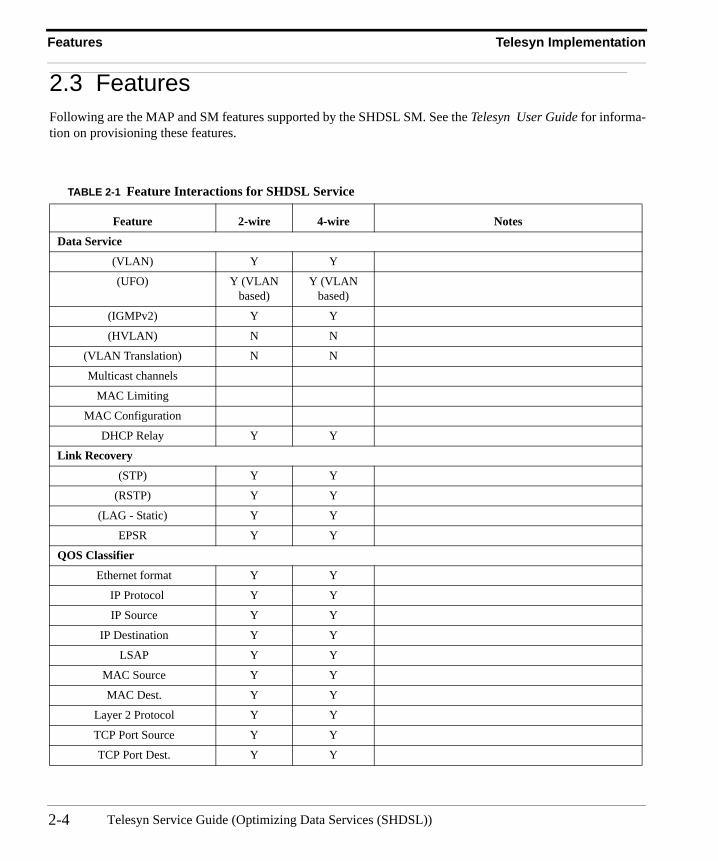
2.3 FeaturesFollowing are the MAP and SM features supported by the SHDSL SM. See the Telesyn User Guide for informa-tion on provisioning these features.
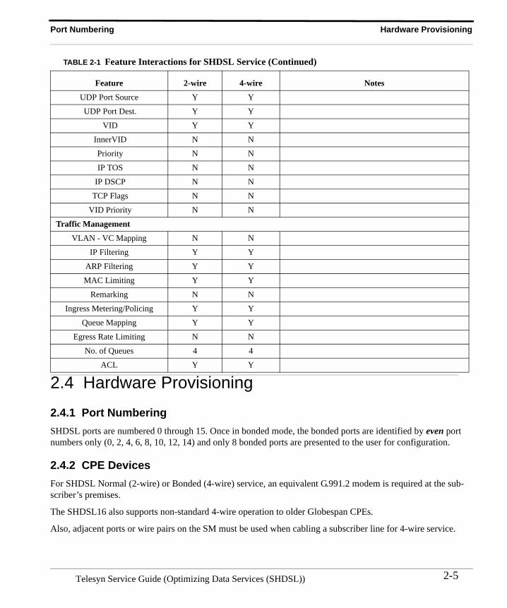
TABLE 2-1 Feature Interactions for SHDSL Service
Feature 2-wire 4-wire Notes
Data Service
(VLAN) Y Y
(UFO) Y (VLAN based)
Y (VLAN based)
(IGMPv2) Y Y
(HVLAN) N N
(VLAN Translation) N N
Multicast channels
MAC Limiting
MAC Configuration
DHCP Relay Y Y
Link Recovery
(STP) Y Y
(RSTP) Y Y
(LAG - Static) Y Y
EPSR Y Y
QOS Classifier
Ethernet format Y Y
IP Protocol Y Y
IP Source Y Y
IP Destination Y Y
LSAP Y Y
MAC Source Y Y
MAC Dest. Y Y
Layer 2 Protocol Y Y
TCP Port Source Y Y
TCP Port Dest. Y Y
Telesyn Service Guide (Optimizing Data Services (SHDSL))2-4
Port Numbering Hardware Provisioning
2.4 Hardware Provisioning
2.4.1 Port NumberingSHDSL ports are numbered 0 through 15. Once in bonded mode, the bonded ports are identified by even port numbers only (0, 2, 4, 6, 8, 10, 12, 14) and only 8 bonded ports are presented to the user for configuration.
2.4.2 CPE DevicesFor SHDSL Normal (2-wire) or Bonded (4-wire) service, an equivalent G.991.2 modem is required at the sub-scriber’s premises.
The SHDSL16 also supports non-standard 4-wire operation to older Globespan CPEs.
Also, adjacent ports or wire pairs on the SM must be used when cabling a subscriber line for 4-wire service.
UDP Port Source Y Y
UDP Port Dest. Y Y
VID Y Y
InnerVID N N
Priority N N
IP TOS N N
IP DSCP N N
TCP Flags N N
VID Priority N N
Traffic Management
VLAN - VC Mapping N N
IP Filtering Y Y
ARP Filtering Y Y
MAC Limiting Y Y
Remarking N N
Ingress Metering/Policing Y Y
Queue Mapping Y Y
Egress Rate Limiting N N
No. of Queues 4 4
ACL Y Y
TABLE 2-1 Feature Interactions for SHDSL Service (Continued)
Feature 2-wire 4-wire Notes
2-5Telesyn Service Guide (Optimizing Data Services (SHDSL))
Software Engineering Interface Association
2.5 Software Engineering
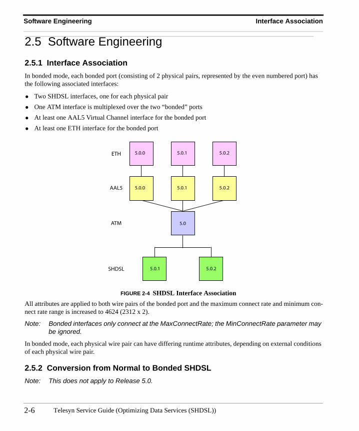
2.5.1 Interface AssociationIn bonded mode, each bonded port (consisting of 2 physical pairs, represented by the even numbered port) has the following associated interfaces:
• Two SHDSL interfaces, one for each physical pair• One ATM interface is multiplexed over the two “bonded” ports• At least one AAL5 Virtual Channel interface for the bonded port• At least one ETH interface for the bonded port
FIGURE 2-4 SHDSL Interface AssociationAll attributes are applied to both wire pairs of the bonded port and the maximum connect rate and minimum con-nect rate range is increased to 4624 (2312 x 2).
Note: Bonded interfaces only connect at the MaxConnectRate; the MinConnectRate parameter may be ignored.
In bonded mode, each physical wire pair can have differing runtime attributes, depending on external conditions of each physical wire pair.
2.5.2 Conversion from Normal to Bonded SHDSLNote: This does not apply to Release 5.0.
5.0.0 5.0.1 5.0.2
5.0.0 5.0.1 5.0.2
5.0.1 5.0.2
5.0
ETH
AAL5
ATM
SHDSL
Telesyn Service Guide (Optimizing Data Services (SHDSL))2-6
SHDSL Port Audit Software Engineering
The following walk-through assumes that card16 is a SHDSL16 card, it has been installed, provisioned, and is in service when the wiremode is modified.
Note: The subscriber’s modem must be configured in 4-wire mode for successful 4-wire operation.
The steps involved are:
1. Disable the card.2. Set the card attribute WIREMODE to bonded.3. Enable the card.
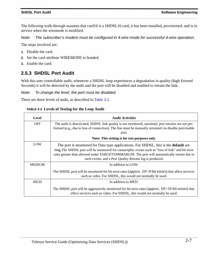
2.5.3 SHDSL Port AuditWith this user controllable audit, whenever a SHDSL loop experiences a degradation in quality (high Errored Seconds) it will be detected by the audit and the port will be disabled and enabled to retrain the link.
Note: To change the level, the port must be disabled.
There are three levels of audit, as described in Table 2-2
TABLE 2-2 Levels of Testing for the Loop Audit
Level Audit Activities
OFF The audit is deactivated, SHDSL link quality is not monitored, automatic port retrains are not per-formed (e.g., due to loss of connection). The line must be manually retrained via disable port/enable
port.
Note: This setting is for test purposes only.
LOW The port is monitored for Data type applications. For SHDSL, this is the default set-ting.The SHDSL port will be monitored for catastrophic events such as “loss of link” and bit error rates greater than allowed under TARGETSNRMARGIN. The port will automatically retrain due to
such events, and a Port Quality Retrain log is produced.
MEDIUM In addition to LOW:
The SHDSL port will be monitored for bit error rates (approx. 10^-9 bit errors) that affect services such as video. For SHDSL, this would not normally be used.
HIGH In addition to MED:
The SHDSL port will be aggressively monitored for bit error rates (approx. 10^-10 bit errors) that effect services such as video. For SHDSL, this would not normally be used.
2-7Telesyn Service Guide (Optimizing Data Services (SHDSL))
Software Engineering SHDSL RMON Statistics
2.5.4 SHDSL RMON Statistics
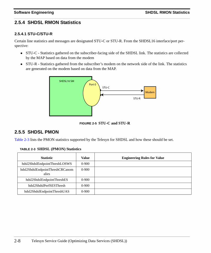
2.5.4.1 STU-C/STU-R
Certain line statistics and messages are designated STU-C or STU-R. From the SHDSL16 interface/port per-spective:
• STU-C - Statistics gathered on the subscriber-facing side of the SHDSL link. The statistics are collected by the MAP based on data from the modem
• STU-R - Statistics gathered from the subscriber’s modem on the network side of the link. The statistics are generated on the modem based on data from the MAP.
FIGURE 2-5 STU-C and STU-R
2.5.5 SHDSL PMONTable 2-3 lists the PMON statistics supported by the Telesyn for SHDSL and how these should be set.
TABLE 2-3 SHDSL (PMON) Statistics
Statistic Value Engineering Rules for Value
hdsl2ShdslEndpointThreshLOSWS 0-900
hdsl2ShdslEndpointThreshCRCanomalies
0-900
hdsl2ShdslEndpointThreshES 0-900
hdsl2ShdslPerfSESThresh 0-900
hdsl2ShdslEndpointThreshUAS 0-900
SHDSL16 SM
Modem
Port 0STU-C
STU-R
Telesyn Service Guide (Optimizing Data Services (SHDSL))2-8
3. Optimizing Video Services
3.1 OverviewVideo service can be configured using either:
• ADSL - This uses the ADSL technology/protocol at the lower protocol layer level that is transported over Ethernet. A typical configuration involves using an ADSL modem at the premesis and an ADSL card at the Telesyn.
• Ethernet - This uses ethernet directly. A typical configuration involves using an Residential Gateway (RG) at the premesis and an Ehternet card (FE or FX) at the Telesyn.
Note: These are example configurations: refer to Section 7 for examples that emply mulitple services.
3.2 Video Services provided by ADSL
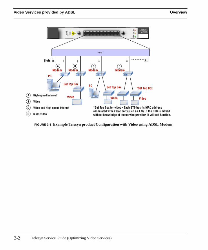
3.2.1 OverviewFigure 3-1 shows the basic Telesyn ADSL product configuration. It shows the customer interface in more detail and shows how video services are configured. System components include the ADSL8S, ADSL16, ADSL16B, and ADSL24 cards.
Since some subscribers may have more than one Set Top Box (STB) at their residence, the ADSL interface can support more than one STB, each needing to support a separate channel. Moreover, one STB may need to support two video channels at once (such as picture within a picture).
Note: Figure 3-1 shows two STBs attached to the ADSL interface. The general configuration rule is that each ADSL interface can support up to three STBs, and the ADSL16 card can support up to 24 STBs. Details on these rules are provided later in this section.
3-1 Telesyn Service Guide (Optimizing Video Services)
Video Services provided by ADSL Overview
FIGURE 3-1 Example Telesyn product Configuration with Video using ADSL Modem
PULLFAULT
INSERV
AD
SL24 TN-112-ATN-112-A
!PINO
UT
SEEU
SER'SM
AN
UA
L
CAT5
Ports
0 231 2 3 4Slots
Modem Modem Modem Modem
PC
A
Set Top Box
Video
B
Video
Set Top BoxPC
C
A High-speed Internet
B Video
C Video and High-speed Internet
D Multi-video
Video
*Set Top Box
D
*Set Top Box for video - Each STB has its MAC addressassociated with a slot.port (such as 4.3). If the STB is movedwithout knowledge of the service provider, it will not function.
Telesyn Service Guide (Optimizing Video Services)3-2
Technology Video Services provided by ADSL
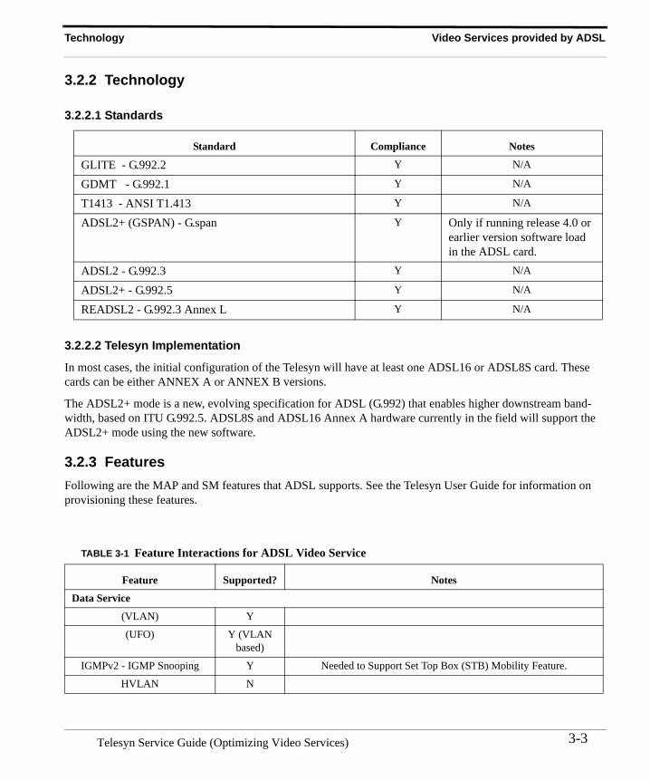
3.2.2 Technology
3.2.2.1 Standards
3.2.2.2 Telesyn Implementation
In most cases, the initial configuration of the Telesyn will have at least one ADSL16 or ADSL8S card. These cards can be either ANNEX A or ANNEX B versions.
The ADSL2+ mode is a new, evolving specification for ADSL (G.992) that enables higher downstream band-width, based on ITU G.992.5. ADSL8S and ADSL16 Annex A hardware currently in the field will support the ADSL2+ mode using the new software.
3.2.3 FeaturesFollowing are the MAP and SM features that ADSL supports. See the Telesyn User Guide for information on provisioning these features.
Standard Compliance Notes
GLITE - G.992.2 Y N/A
GDMT - G.992.1 Y N/A
T1413 - ANSI T1.413 Y N/A
ADSL2+ (GSPAN) - G.span Y Only if running release 4.0 or earlier version software load in the ADSL card.
ADSL2 - G.992.3 Y N/A
ADSL2+ - G.992.5 Y N/A
READSL2 - G.992.3 Annex L Y N/A
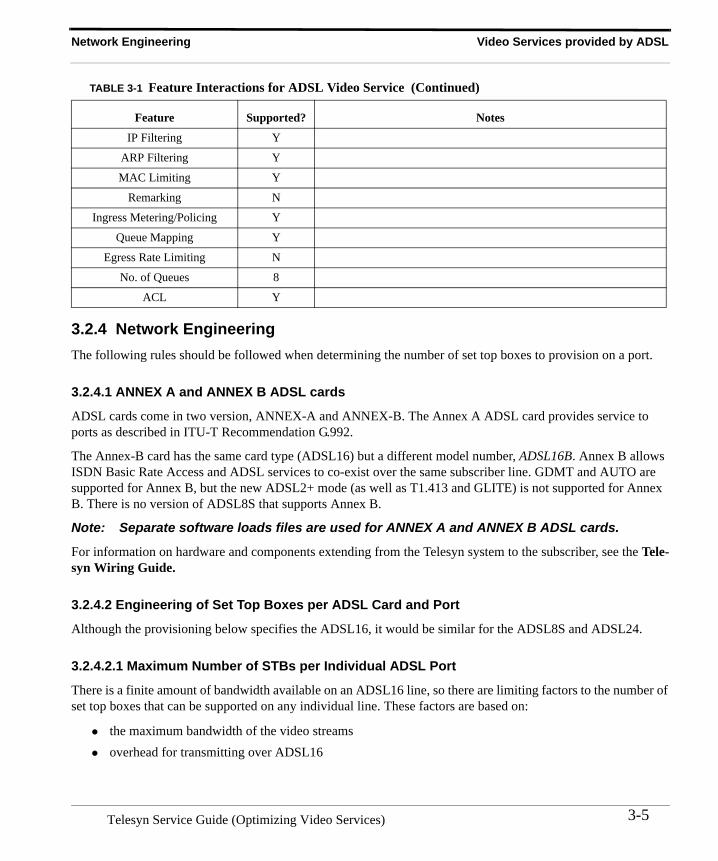
TABLE 3-1 Feature Interactions for ADSL Video Service
Feature Supported? Notes
Data Service
(VLAN) Y
(UFO) Y (VLAN based)
IGMPv2 - IGMP Snooping Y Needed to Support Set Top Box (STB) Mobility Feature.
HVLAN N
3-3Telesyn Service Guide (Optimizing Video Services)
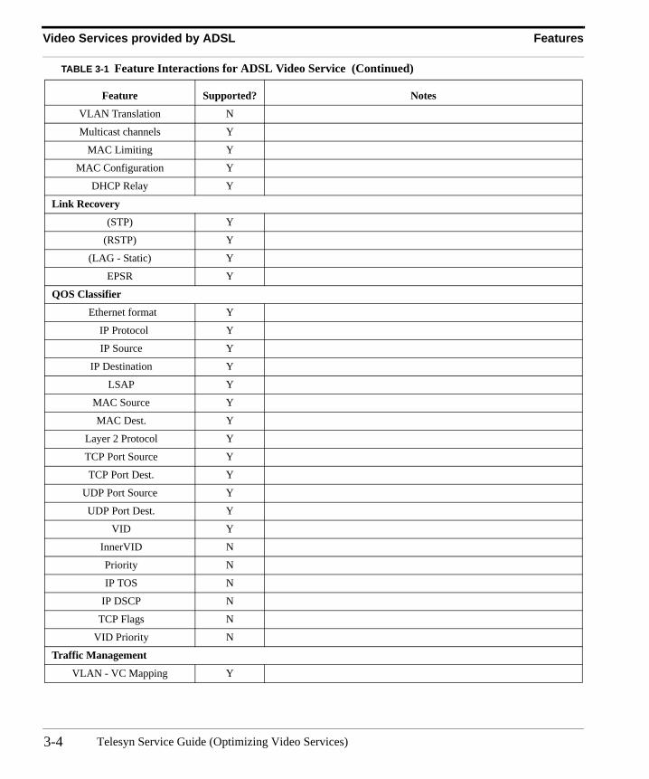
Video Services provided by ADSL Features
VLAN Translation N
Multicast channels Y
MAC Limiting Y
MAC Configuration Y
DHCP Relay Y
Link Recovery
(STP) Y
(RSTP) Y
(LAG - Static) Y
EPSR Y
QOS Classifier
Ethernet format Y
IP Protocol Y
IP Source Y
IP Destination Y
LSAP Y
MAC Source Y
MAC Dest. Y
Layer 2 Protocol Y
TCP Port Source Y
TCP Port Dest. Y
UDP Port Source Y
UDP Port Dest. Y
VID Y
InnerVID N
Priority N
IP TOS N
IP DSCP N
TCP Flags N
VID Priority N
Traffic Management
VLAN - VC Mapping Y
TABLE 3-1 Feature Interactions for ADSL Video Service (Continued)
Feature Supported? Notes
Telesyn Service Guide (Optimizing Video Services)3-4
Network Engineering Video Services provided by ADSL
3.2.4 Network EngineeringThe following rules should be followed when determining the number of set top boxes to provision on a port.
3.2.4.1 ANNEX A and ANNEX B ADSL cards
ADSL cards come in two version, ANNEX-A and ANNEX-B. The Annex A ADSL card provides service to ports as described in ITU-T Recommendation G.992.
The Annex-B card has the same card type (ADSL16) but a different model number, ADSL16B. Annex B allows ISDN Basic Rate Access and ADSL services to co-exist over the same subscriber line. GDMT and AUTO are supported for Annex B, but the new ADSL2+ mode (as well as T1.413 and GLITE) is not supported for Annex B. There is no version of ADSL8S that supports Annex B.
Note: Separate software loads files are used for ANNEX A and ANNEX B ADSL cards.
For information on hardware and components extending from the Telesyn system to the subscriber, see the Tele-syn Wiring Guide.
3.2.4.2 Engineering of Set Top Boxes per ADSL Card and Port
Although the provisioning below specifies the ADSL16, it would be similar for the ADSL8S and ADSL24.
3.2.4.2.1 Maximum Number of STBs per Individual ADSL Port
There is a finite amount of bandwidth available on an ADSL16 line, so there are limiting factors to the number of set top boxes that can be supported on any individual line. These factors are based on:
• the maximum bandwidth of the video streams• overhead for transmitting over ADSL16
IP Filtering Y
ARP Filtering Y
MAC Limiting Y
Remarking N
Ingress Metering/Policing Y
Queue Mapping Y
Egress Rate Limiting N
No. of Queues 8
ACL Y
TABLE 3-1 Feature Interactions for ADSL Video Service (Continued)
Feature Supported? Notes
3-5Telesyn Service Guide (Optimizing Video Services)
Video Services provided by ADSL Network Engineering
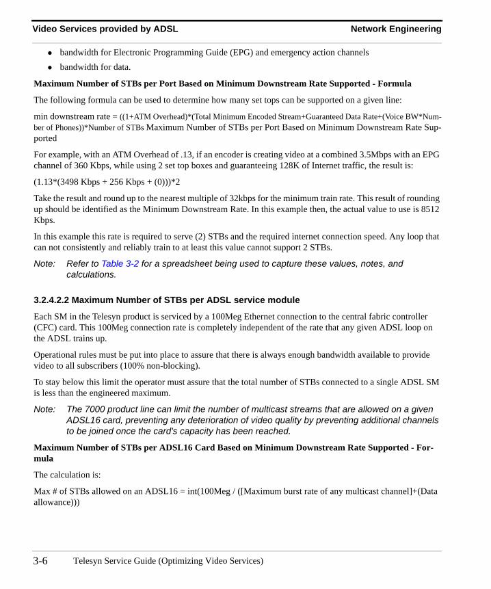
• bandwidth for Electronic Programming Guide (EPG) and emergency action channels• bandwidth for data.
Maximum Number of STBs per Port Based on Minimum Downstream Rate Supported - Formula
The following formula can be used to determine how many set tops can be supported on a given line:
min downstream rate = ((1+ATM Overhead)*(Total Minimum Encoded Stream+Guaranteed Data Rate+(Voice BW*Num-ber of Phones))*Number of STBs Maximum Number of STBs per Port Based on Minimum Downstream Rate Sup-ported
For example, with an ATM Overhead of .13, if an encoder is creating video at a combined 3.5Mbps with an EPG channel of 360 Kbps, while using 2 set top boxes and guaranteeing 128K of Internet traffic, the result is:
(1.13*(3498 Kbps + 256 Kbps + (0)))*2
Take the result and round up to the nearest multiple of 32kbps for the minimum train rate. This result of rounding up should be identified as the Minimum Downstream Rate. In this example then, the actual value to use is 8512 Kbps.
In this example this rate is required to serve (2) STBs and the required internet connection speed. Any loop that can not consistently and reliably train to at least this value cannot support 2 STBs.
Note: Refer to Table 3-2 for a spreadsheet being used to capture these values, notes, and calculations.
3.2.4.2.2 Maximum Number of STBs per ADSL service module
Each SM in the Telesyn product is serviced by a 100Meg Ethernet connection to the central fabric controller (CFC) card. This 100Meg connection rate is completely independent of the rate that any given ADSL loop on the ADSL trains up.
Operational rules must be put into place to assure that there is always enough bandwidth available to provide video to all subscribers (100% non-blocking).
To stay below this limit the operator must assure that the total number of STBs connected to a single ADSL SM is less than the engineered maximum.
Note: The 7000 product line can limit the number of multicast streams that are allowed on a given ADSL16 card, preventing any deterioration of video quality by preventing additional channels to be joined once the card's capacity has been reached.
Maximum Number of STBs per ADSL16 Card Based on Minimum Downstream Rate Supported - For-mula
The calculation is:
Max # of STBs allowed on an ADSL16 = int(100Meg / ([Maximum burst rate of any multicast channel]+(Data allowance)))
Telesyn Service Guide (Optimizing Video Services)3-6
Network Engineering Video Services provided by ADSL
Some Video encoders produce inherently bursty data streams, particularly those which attempt to rate-limit digi-tal satellite channels. This must be accounted for in the calculations by assuming that all STBs on the ADSL16 could be watching a different “bursty” channel. Again, the user must assume a 100% non-blocking engineering rule for bandwidth in order to avoid video disruption for the customer.
Maximum Number of STBs per ADSL16 Card Based on Minimum Downstream Rate Supported - Exam-ple
For example, if it is found through network inspection at the head-end that the maximum burst rate on the com-bined audio/video channels is 4Mb/sec., and .5Mb is requested for minimum internet connection for the subscrib-ers grouped on the SM. The calculation is:
Int(100Mb/(4.0Mb + .5Mb)) = 24 STBs per ADSL16
3.2.4.2.3 Minimum and Maximum Downstream Rate Calculations per System
When an ADSL16 loop trains to a particular data rate the environmental factors at the moment may cause it to train lower or higher then normal. Examples would include lightning storms.
• Training too low may mean that the loop won't provide enough bandwidth for the number of STBs attached, causing video disruption.
• Some modems have a tendency to train higher than what can be sustained over time, which may lead to a higher number of errored seconds than normal, which can also cause video disruption.
There is also an error correction advantage in setting a maximum train rate which is lower then the actual maxi-mum a loop can support. In such a case the ADSL16 loop can take advantage of excess bandwidth to correct for noise on the loop. (Note: This requires bitswapping to be enabled in the ADSL16 modem).
It is recommended that a system-wide minimum and maximum train rate be set for all loops. The numbers used here would be for most subscribers, typically 0-10000 ft., which can expect to reach train rates to support two STBs.
For longer loops, or loops with interferers on them which prevent training to the Minimum Downstream Rate, a second training profile can be applied based on a single STB. In other words, if a loop does not train up to the recommended minimum downstream rate, then it can only support one STB.
The formula for the Minimum Downstream Rate is the same as in Table 3-2. As part of the installation process the operator should verify that a loop can normally reach the minimum downstream rate without issue. In event of a poor retrain in the future (example: ADSL16 retrain during a lighting burst) the system will automatically attempt to recover by retraining the loop until the minimum is reached.
3-7Telesyn Service Guide (Optimizing Video Services)
Video Services provided by ADSL Network Engineering
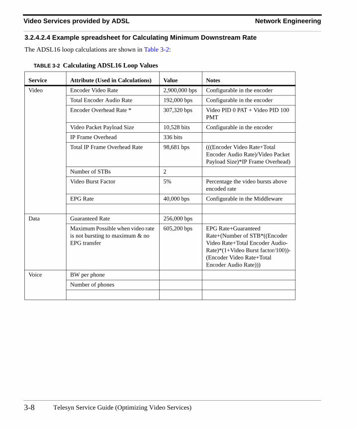
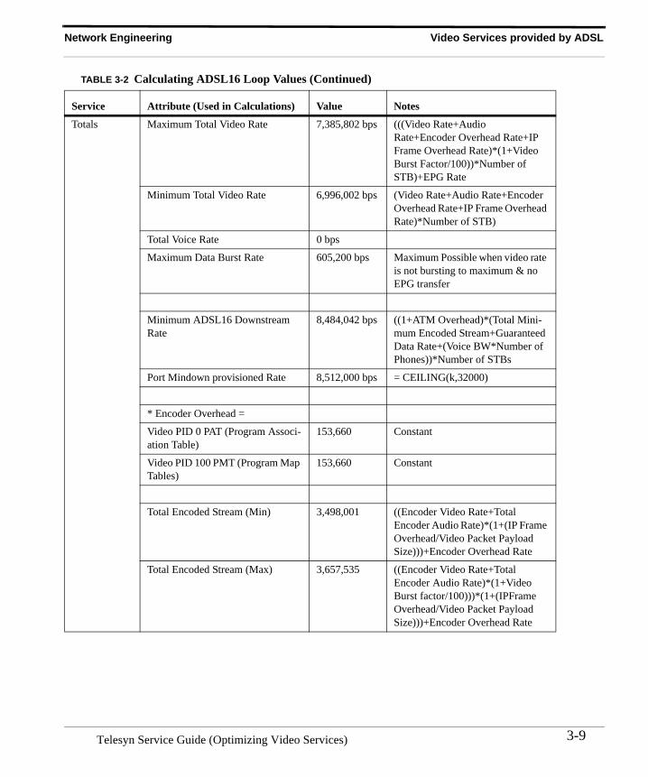
3.2.4.2.4 Example spreadsheet for Calculating Minimum Downstream Rate
The ADSL16 loop calculations are shown in Table 3-2:
TABLE 3-2 Calculating ADSL16 Loop Values
Service Attribute (Used in Calculations) Value Notes
Video Encoder Video Rate 2,900,000 bps Configurable in the encoder
Total Encoder Audio Rate 192,000 bps Configurable in the encoder
Encoder Overhead Rate * 307,320 bps Video PID 0 PAT + Video PID 100 PMT
Video Packet Payload Size 10,528 bits Configurable in the encoder
IP Frame Overhead 336 bits
Total IP Frame Overhead Rate 98,681 bps (((Encoder Video Rate+Total Encoder Audio Rate)/Video Packet Payload Size)*IP Frame Overhead)
Number of STBs 2
Video Burst Factor 5% Percentage the video bursts above encoded rate
EPG Rate 40,000 bps Configurable in the Middleware
Data Guaranteed Rate 256,000 bps
Maximum Possible when video rate is not bursting to maximum & no EPG transfer
605,200 bps EPG Rate+Guaranteed Rate+(Number of STB*((Encoder Video Rate+Total Encoder Audio-Rate)*(1+Video Burst factor/100))-(Encoder Video Rate+Total Encoder Audio Rate)))
Voice BW per phone
Number of phones
Telesyn Service Guide (Optimizing Video Services)3-8
Network Engineering Video Services provided by ADSL
Totals Maximum Total Video Rate 7,385,802 bps (((Video Rate+Audio Rate+Encoder Overhead Rate+IP Frame Overhead Rate)*(1+Video Burst Factor/100))*Number of STB)+EPG Rate
Minimum Total Video Rate 6,996,002 bps (Video Rate+Audio Rate+Encoder Overhead Rate+IP Frame Overhead Rate)*Number of STB)
Total Voice Rate 0 bps
Maximum Data Burst Rate 605,200 bps Maximum Possible when video rate is not bursting to maximum & no EPG transfer
Minimum ADSL16 Downstream Rate
8,484,042 bps ((1+ATM Overhead)*(Total Mini-mum Encoded Stream+Guaranteed Data Rate+(Voice BW*Number of Phones))*Number of STBs
Port Mindown provisioned Rate 8,512,000 bps = CEILING(k,32000)
* Encoder Overhead =
Video PID 0 PAT (Program Associ-ation Table)
153,660 Constant
Video PID 100 PMT (Program Map Tables)
153,660 Constant
Total Encoded Stream (Min) 3,498,001 ((Encoder Video Rate+Total Encoder Audio Rate)*(1+(IP Frame Overhead/Video Packet Payload Size)))+Encoder Overhead Rate
Total Encoded Stream (Max) 3,657,535 ((Encoder Video Rate+Total Encoder Audio Rate)*(1+Video Burst factor/100)))*(1+(IPFrame Overhead/Video Packet Payload Size)))+Encoder Overhead Rate
TABLE 3-2 Calculating ADSL16 Loop Values (Continued)
Service Attribute (Used in Calculations) Value Notes
3-9Telesyn Service Guide (Optimizing Video Services)
Video Services provided by ADSL Software Engineering
3.2.4.3 Engineering of STBs for the ADSL24
Calculations for the maximum number of STBs per port are the same for the ADSL24 SM as those discussed above for the ADSL16 and ADSL8S. Refer to Figure 3.2.4.2 for more information. 3 STBs per ADSL24 port is the norm.
3.2.4.4 ADSL IGMP Video ConfigurationFor each ADSL interface, the following can be configured for the specified Telesyn:
• Three STB with Five streams per STB• One channel change per STB per second
3.2.5 Software Engineering
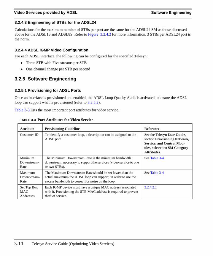
3.2.5.1 Provisioning for ADSL Ports
Once an interface is provisioned and enabled, the ADSL Loop Quality Audit is activated to ensure the ADSL loop can support what is provisioned (refer to 3.2.5.2).
Table 3-3 lists the most important port attributes for video service.
TABLE 3-3 Port Attributes for Video Service
Attribute Provisioning Guideline Reference
Customer ID To identify a customer loop, a description can be assigned to the ADSL port
See the Telesyn User Guide, section Provisioning Network, Service, and Control Mod-ules, subsection SM Category Attributes.
Minimum Downstream-Rate
The Minimum Downstream Rate is the minimum bandwidth downstream necessary to support the services (video service to one or two STBs).
See Table 3-4
Maximum DownStream-Rate
The Maximum Downstream Rate should be set lower than the actual maximum the ADSL loop can support, in order to use the excess bandwidth to correct for noise on the loop.
See Table 3-4
Set Top Box MAC Addresses
Each IGMP device must have a unique MAC address associated with it. Provisioning the STB MAC address is required to prevent theft of service.
3.2.4.2.1
Telesyn Service Guide (Optimizing Video Services)3-10
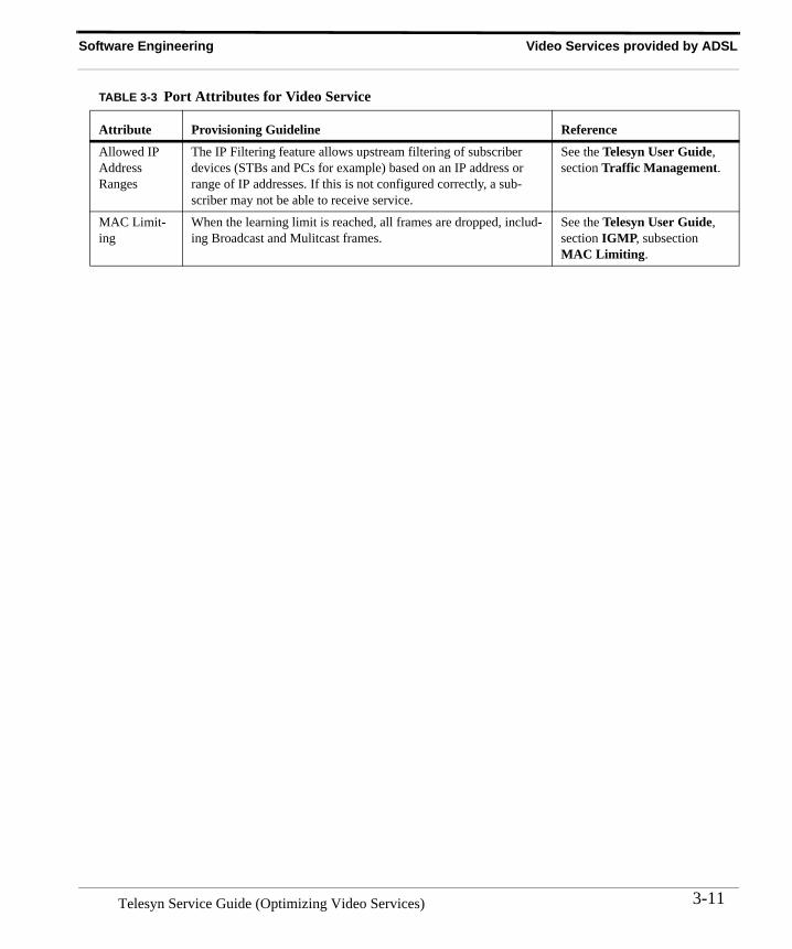
Software Engineering Video Services provided by ADSL
Allowed IP Address Ranges
The IP Filtering feature allows upstream filtering of subscriber devices (STBs and PCs for example) based on an IP address or range of IP addresses. If this is not configured correctly, a sub-scriber may not be able to receive service.
See the Telesyn User Guide, section Traffic Management.
MAC Limit-ing
When the learning limit is reached, all frames are dropped, includ-ing Broadcast and Mulitcast frames.
See the Telesyn User Guide, section IGMP, subsection MAC Limiting.
TABLE 3-3 Port Attributes for Video Service
Attribute Provisioning Guideline Reference
3-11Telesyn Service Guide (Optimizing Video Services)
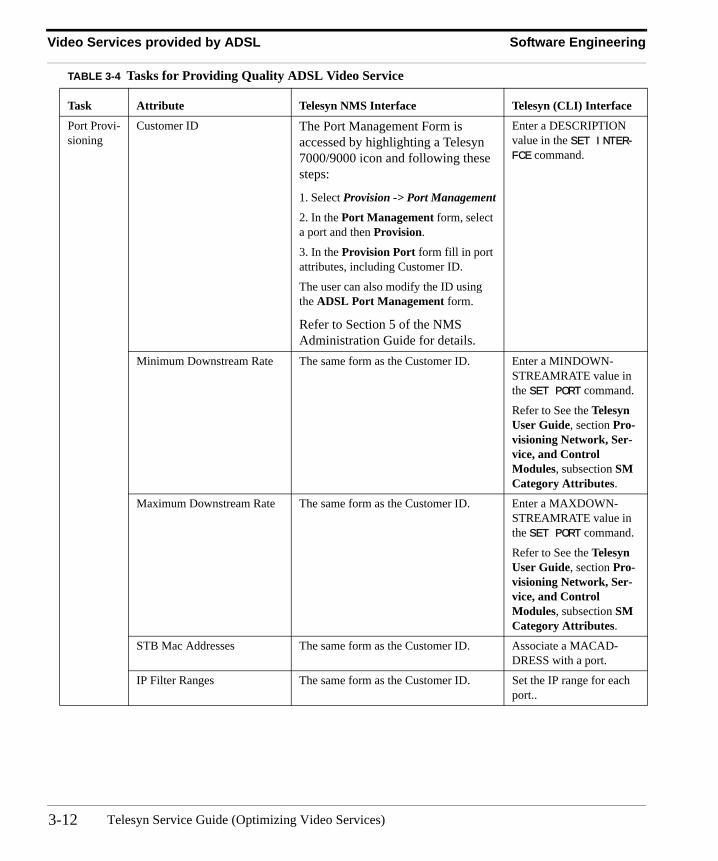
Video Services provided by ADSL Software Engineering
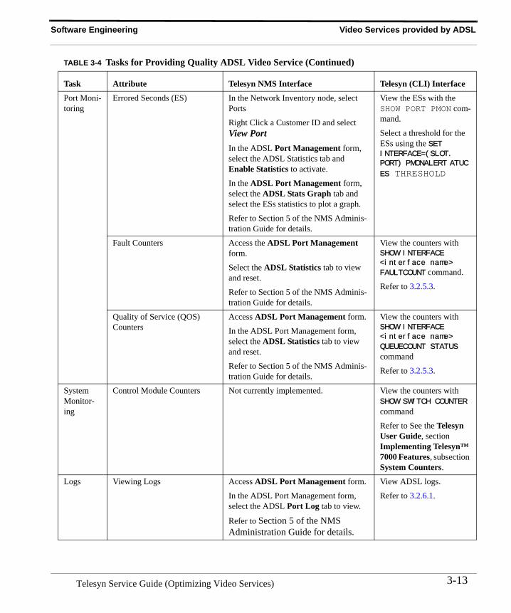
TABLE 3-4 Tasks for Providing Quality ADSL Video Service
Task Attribute Telesyn NMS Interface Telesyn (CLI) Interface
Port Provi-sioning
Customer ID The Port Management Form is accessed by highlighting a Telesyn 7000/9000 icon and following these steps:
1. Select Provision -> Port Management
2. In the Port Management form, select a port and then Provision.
3. In the Provision Port form fill in port attributes, including Customer ID.
The user can also modify the ID using the ADSL Port Management form.
Refer to Section 5 of the NMS Administration Guide for details.
Enter a DESCRIPTION value in the SET INTER-FCE command.
Minimum Downstream Rate The same form as the Customer ID. Enter a MINDOWN-STREAMRATE value in the SET PORT command.
Refer to See the Telesyn User Guide, section Pro-visioning Network, Ser-vice, and Control Modules, subsection SM Category Attributes.
Maximum Downstream Rate The same form as the Customer ID. Enter a MAXDOWN-STREAMRATE value in the SET PORT command.
Refer to See the Telesyn User Guide, section Pro-visioning Network, Ser-vice, and Control Modules, subsection SM Category Attributes.
STB Mac Addresses The same form as the Customer ID. Associate a MACAD-DRESS with a port.
IP Filter Ranges The same form as the Customer ID. Set the IP range for each port..
Telesyn Service Guide (Optimizing Video Services)3-12
Software Engineering Video Services provided by ADSL
Port Moni-toring
Errored Seconds (ES) In the Network Inventory node, select Ports
Right Click a Customer ID and select View PortIn the ADSL Port Management form, select the ADSL Statistics tab and Enable Statistics to activate.
In the ADSL Port Management form, select the ADSL Stats Graph tab and select the ESs statistics to plot a graph.
Refer to Section 5 of the NMS Adminis-tration Guide for details.
View the ESs with the SHOW PORT PMON com-mand.
Select a threshold for the ESs using the SET INTERFACE=(SLOT.
PORT) PMONALERT ATUC
ES THRESHOLD
Fault Counters Access the ADSL Port Management form.
Select the ADSL Statistics tab to view and reset.
Refer to Section 5 of the NMS Adminis-tration Guide for details.
View the counters with SHOW INTERFACE
<interface name>
FAULTCOUNT command.
Refer to 3.2.5.3.
Quality of Service (QOS) Counters
Access ADSL Port Management form.
In the ADSL Port Management form, select the ADSL Statistics tab to view and reset.
Refer to Section 5 of the NMS Adminis-tration Guide for details.
View the counters with SHOW INTERFACE
<interface name>
QUEUECOUNT STATUS command
Refer to 3.2.5.3.
System Monitor-ing
Control Module Counters Not currently implemented. View the counters with SHOW SWITCH COUNTER command
Refer to See the Telesyn User Guide, section Implementing Telesyn™ 7000 Features, subsection System Counters.
Logs Viewing Logs Access ADSL Port Management form.
In the ADSL Port Management form, select the ADSL Port Log tab to view.
Refer to Section 5 of the NMS Administration Guide for details.
View ADSL logs.
Refer to 3.2.6.1.
TABLE 3-4 Tasks for Providing Quality ADSL Video Service (Continued)
Task Attribute Telesyn NMS Interface Telesyn (CLI) Interface
3-13Telesyn Service Guide (Optimizing Video Services)
Video Services provided by ADSL Software Engineering
3.2.5.2 ADSL Loop Quality Audit
Without this audit, an ADSL port would detect a Loss of Link and would try to re-enable the link. In applications such as video, however, a degradation (rather than a loss) of the loop quality could still make the video unusable.
With this audit, whenever an ADSL loop experiences a degradation in quality (high Errored Seconds) it will be detected by the audit and the port will be disabled and enabled to retrain the link.
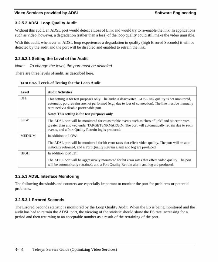
3.2.5.2.1 Setting the Level of the Audit
Note: To change the level, the port must be disabled.
There are three levels of audit, as described here.
3.2.5.3 ADSL Interface Monitoring
The following thresholds and counters are especially important to monitor the port for problems or potential problems.
3.2.5.3.1 Errored Seconds
The Errored Seconds statistic is monitored by the Loop Quality Audit. When the ES is being monitored and the audit has had to retrain the ADSL port, the viewing of the statistic should show the ES rate increasing for a period and then returning to an acceptable number as a result of the retraining of the port.
TABLE 3-5 Levels of Testing for the Loop Audit
Level Audit Activities
OFF This setting is for test purposes only. The audit is deactivated, ADSL link quality is not monitored, automatic port retrains are not performed (e.g., due to loss of connection). The line must be manually retrained via disable port/enable port.
Note: This setting is for test purposes only.
LOW The ADSL port will be monitored for catastrophic events such as “loss of link” and bit error rates greater than allowed under TARGETSNRMARGIN. The port will automatically retrain due to such events, and a Port Quality Retrain log is produced.
MEDIUM In addition to LOW:
The ADSL port will be monitored for bit error rates that effect video quality. The port will be auto-matically retrained, and a Port Quality Retrain alarm and log are produced.
HIGH In addition to MED:
The ADSL port will be aggressively monitored for bit error rates that effect video quality. The port will be automatically retrained, and a Port Quality Retrain alarm and log are produced.
Telesyn Service Guide (Optimizing Video Services)3-14
Software Engineering Video Services provided by ADSL
In addition to the monitoring of ES that is done by the audit, ES should be monitored by the network engineer. A threshold should be set at 100 ES/hour to monitor both the quality of the loop and the performance of the audit. This threshold is higher than what the audit provides for the following reasons:
• If the higher threshold is passed and its related log is produced, there is a problem on the port that the audit cannot resolve (such as permanent physical impairments), and further troubleshooting is required.
• The performance of the audit can be monitored, and in the unlikely event the audit was not running, the higher threshold would catch the rise in ESs and the log would indicate when it occurred.
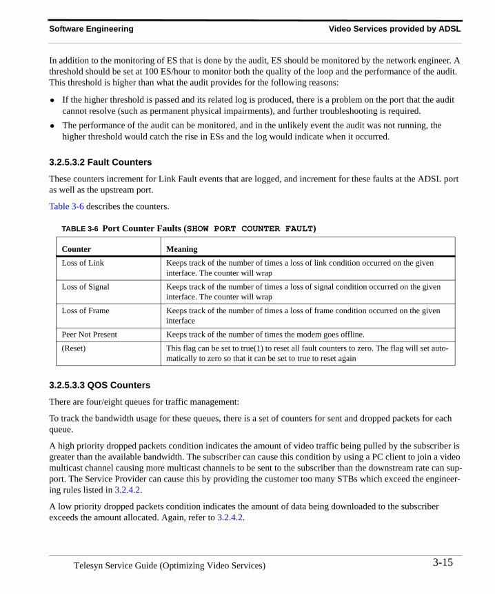
3.2.5.3.2 Fault Counters
These counters increment for Link Fault events that are logged, and increment for these faults at the ADSL port as well as the upstream port.
Table 3-6 describes the counters.
3.2.5.3.3 QOS Counters
There are four/eight queues for traffic management:
To track the bandwidth usage for these queues, there is a set of counters for sent and dropped packets for each queue.
A high priority dropped packets condition indicates the amount of video traffic being pulled by the subscriber is greater than the available bandwidth. The subscriber can cause this condition by using a PC client to join a video multicast channel causing more multicast channels to be sent to the subscriber than the downstream rate can sup-port. The Service Provider can cause this by providing the customer too many STBs which exceed the engineer-ing rules listed in 3.2.4.2.
A low priority dropped packets condition indicates the amount of data being downloaded to the subscriber exceeds the amount allocated. Again, refer to 3.2.4.2.
TABLE 3-6 Port Counter Faults (SHOW PORT COUNTER FAULT)
Counter Meaning
Loss of Link Keeps track of the number of times a loss of link condition occurred on the given interface. The counter will wrap
Loss of Signal Keeps track of the number of times a loss of signal condition occurred on the given interface. The counter will wrap
Loss of Frame Keeps track of the number of times a loss of frame condition occurred on the given interface
Peer Not Present Keeps track of the number of times the modem goes offline.
(Reset) This flag can be set to true(1) to reset all fault counters to zero. The flag will set auto-matically to zero so that it can be set to true to reset again
3-15Telesyn Service Guide (Optimizing Video Services)
Video Services provided by ADSL Software Engineering
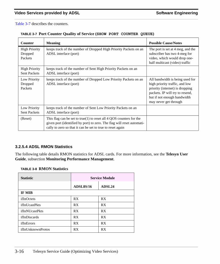
Table 3-7 describes the counters.
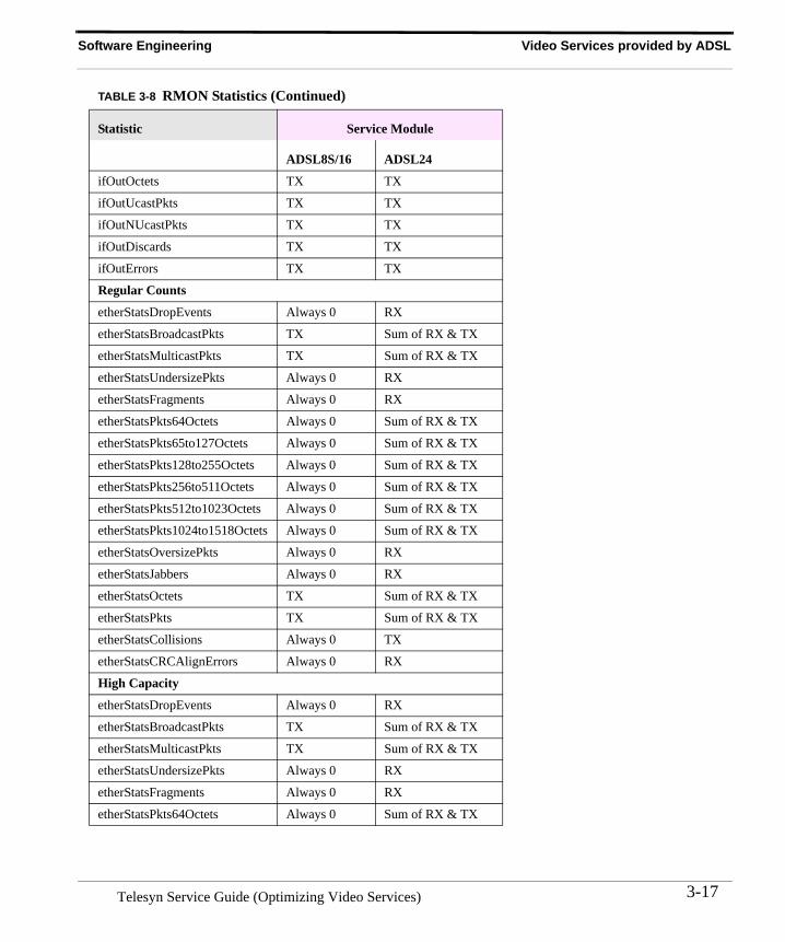
3.2.5.4 ADSL RMON Statistics
The following table details RMON statistics for ADSL cards. For more information, see the Telesyn User Guide, subsection Monitoring Performance Management.
TABLE 3-7 Port Counter Quality of Service (SHOW PORT COUNTER QUEUE)
Counter Meaning Possible Cause/Notes
High Priority Dropped Packets
keeps track of the number of Dropped High Priority Packets on an ADSL interface (port)
The port is set at 4 meg, and the subscriber has two 4-meg for video, which would drop one-half multicast (video) traffic
High Priority Sent Packets
keeps track of the number of Sent High Priority Packets on an ADSL interface (port)
Low Priority Dropped Packets
keeps track of the number of Dropped Low Priority Packets on an ADSL interface (port)
All bandwidth is being used for high priority traffic, and low priority (internet) is dropping packets. IP will try to resend, but if not enough bandwidth may never get through
Low Priority Sent Packets
keeps track of the number of Sent Low Priority Packets on an ADSL interface (port)
(Reset) This flag can be set to true(1) to reset all 4 QOS counters for the given port (identified by port) to zero. The flag will reset automati-cally to zero so that it can be set to true to reset again
TABLE 3-8 RMON Statistics
Statistic Service Module
ADSL8S/16 ADSL24
IF MIB
ifInOctets RX RX
ifInUcastPkts RX RX
ifInNUcastPkts RX RX
ifInDiscards RX RX
ifInErrors RX RX
ifInUnknownProtos RX RX
Telesyn Service Guide (Optimizing Video Services)3-16
Software Engineering Video Services provided by ADSL
ifOutOctets TX TX
ifOutUcastPkts TX TX
ifOutNUcastPkts TX TX
ifOutDiscards TX TX
ifOutErrors TX TX
Regular Counts
etherStatsDropEvents Always 0 RX
etherStatsBroadcastPkts TX Sum of RX & TX
etherStatsMulticastPkts TX Sum of RX & TX
etherStatsUndersizePkts Always 0 RX
etherStatsFragments Always 0 RX
etherStatsPkts64Octets Always 0 Sum of RX & TX
etherStatsPkts65to127Octets Always 0 Sum of RX & TX
etherStatsPkts128to255Octets Always 0 Sum of RX & TX
etherStatsPkts256to511Octets Always 0 Sum of RX & TX
etherStatsPkts512to1023Octets Always 0 Sum of RX & TX
etherStatsPkts1024to1518Octets Always 0 Sum of RX & TX
etherStatsOversizePkts Always 0 RX
etherStatsJabbers Always 0 RX
etherStatsOctets TX Sum of RX & TX
etherStatsPkts TX Sum of RX & TX
etherStatsCollisions Always 0 TX
etherStatsCRCAlignErrors Always 0 RX
High Capacity
etherStatsDropEvents Always 0 RX
etherStatsBroadcastPkts TX Sum of RX & TX
etherStatsMulticastPkts TX Sum of RX & TX
etherStatsUndersizePkts Always 0 RX
etherStatsFragments Always 0 RX
etherStatsPkts64Octets Always 0 Sum of RX & TX
TABLE 3-8 RMON Statistics (Continued)
Statistic Service Module
ADSL8S/16 ADSL24
3-17Telesyn Service Guide (Optimizing Video Services)
Video Services provided by ADSL Software Engineering
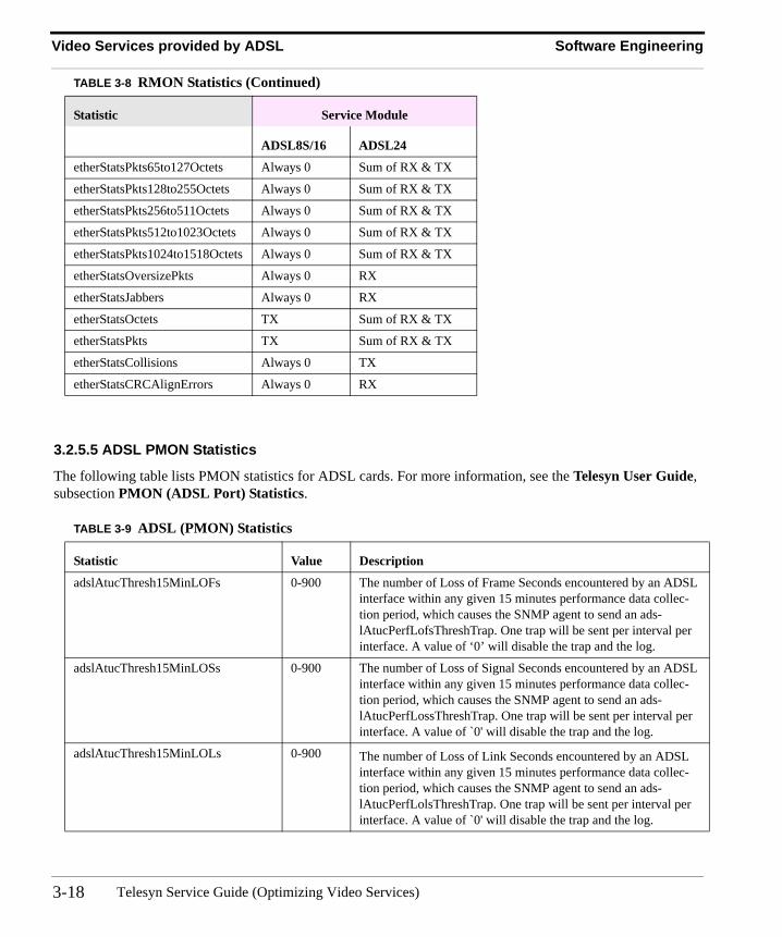
3.2.5.5 ADSL PMON Statistics
The following table lists PMON statistics for ADSL cards. For more information, see the Telesyn User Guide, subsection PMON (ADSL Port) Statistics.
etherStatsPkts65to127Octets Always 0 Sum of RX & TX
etherStatsPkts128to255Octets Always 0 Sum of RX & TX
etherStatsPkts256to511Octets Always 0 Sum of RX & TX
etherStatsPkts512to1023Octets Always 0 Sum of RX & TX
etherStatsPkts1024to1518Octets Always 0 Sum of RX & TX
etherStatsOversizePkts Always 0 RX
etherStatsJabbers Always 0 RX
etherStatsOctets TX Sum of RX & TX
etherStatsPkts TX Sum of RX & TX
etherStatsCollisions Always 0 TX
etherStatsCRCAlignErrors Always 0 RX
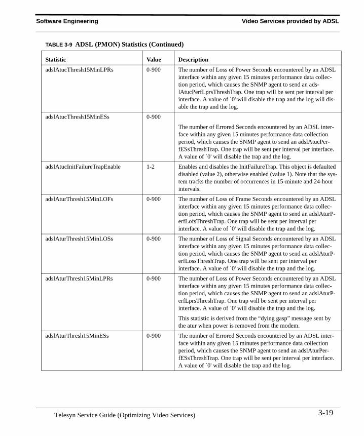
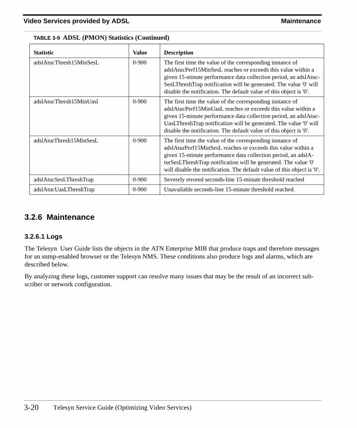
TABLE 3-9 ADSL (PMON) Statistics
Statistic Value Description
adslAtucThresh15MinLOFs 0-900 The number of Loss of Frame Seconds encountered by an ADSL interface within any given 15 minutes performance data collec-tion period, which causes the SNMP agent to send an ads-lAtucPerfLofsThreshTrap. One trap will be sent per interval per interface. A value of ‘0’ will disable the trap and the log.
adslAtucThresh15MinLOSs 0-900 The number of Loss of Signal Seconds encountered by an ADSL interface within any given 15 minutes performance data collec-tion period, which causes the SNMP agent to send an ads-lAtucPerfLossThreshTrap. One trap will be sent per interval per interface. A value of `0' will disable the trap and the log.
adslAtucThresh15MinLOLs 0-900 The number of Loss of Link Seconds encountered by an ADSL interface within any given 15 minutes performance data collec-tion period, which causes the SNMP agent to send an ads-lAtucPerfLolsThreshTrap. One trap will be sent per interval per interface. A value of `0' will disable the trap and the log.
TABLE 3-8 RMON Statistics (Continued)
Statistic Service Module
ADSL8S/16 ADSL24
Telesyn Service Guide (Optimizing Video Services)3-18
Software Engineering Video Services provided by ADSL
adslAtucThresh15MinLPRs 0-900 The number of Loss of Power Seconds encountered by an ADSL interface within any given 15 minutes performance data collec-tion period, which causes the SNMP agent to send an ads-lAtucPerfLprsThreshTrap. One trap will be sent per interval per interface. A value of `0' will disable the trap and the log will dis-able the trap and the log.
adslAtucThresh15MinESs 0-900
The number of Errored Seconds encountered by an ADSL inter-face within any given 15 minutes performance data collection period, which causes the SNMP agent to send an adslAtucPer-fESsThreshTrap. One trap will be sent per interval per interface. A value of `0' will disable the trap and the log.
adslAtucInitFailureTrapEnable 1-2 Enables and disables the InitFailureTrap. This object is defaulted disabled (value 2), otherwise enabled (value 1). Note that the sys-tem tracks the number of occurrences in 15-minute and 24-hour intervals.
adslAturThresh15MinLOFs 0-900 The number of Loss of Frame Seconds encountered by an ADSL interface within any given 15 minutes performance data collec-tion period, which causes the SNMP agent to send an adslAturP-erfLofsThreshTrap. One trap will be sent per interval per interface. A value of `0' will disable the trap and the log.
adslAturThresh15MinLOSs 0-900 The number of Loss of Signal Seconds encountered by an ADSL interface within any given 15 minutes performance data collec-tion period, which causes the SNMP agent to send an adslAturP-erfLossThreshTrap. One trap will be sent per interval per interface. A value of `0' will disable the trap and the log.
adslAturThresh15MinLPRs 0-900 The number of Loss of Power Seconds encountered by an ADSL interface within any given 15 minutes performance data collec-tion period, which causes the SNMP agent to send an adslAturP-erfLprsThreshTrap. One trap will be sent per interval per interface. A value of `0' will disable the trap and the log.
This statistic is derived from the “dying gasp” message sent by the atur when power is removed from the modem.
adslAturThresh15MinESs 0-900 The number of Errored Seconds encountered by an ADSL inter-face within any given 15 minutes performance data collection period, which causes the SNMP agent to send an adslAturPer-fESsThreshTrap. One trap will be sent per interval per interface. A value of `0' will disable the trap and the log.
TABLE 3-9 ADSL (PMON) Statistics (Continued)
Statistic Value Description
3-19Telesyn Service Guide (Optimizing Video Services)
Video Services provided by ADSL Maintenance
3.2.6 Maintenance
3.2.6.1 Logs
The Telesyn User Guide lists the objects in the ATN Enterprise MIB that produce traps and therefore messages for an snmp-enabled browser or the Telesyn NMS. These conditions also produce logs and alarms, which are described below.
By analyzing these logs, customer support can resolve many issues that may be the result of an incorrect sub-scriber or network configuration.
adslAtucThresh15MinSesL 0-900 The first time the value of the corresponding instance of adslAtucPerf15MinSesL reaches or exceeds this value within a given 15-minute performance data collection period, an adslAtuc-SesLThreshTrap notification will be generated. The value '0' will disable the notification. The default value of this object is '0'.
adslAtucThresh15MinUasl 0-900 The first time the value of the corresponding instance of adslAtucPerf15MinUasL reaches or exceeds this value within a given 15-minute performance data collection period, an adslAtuc-UasLThreshTrap notification will be generated. The value '0' will disable the notification. The default value of this object is '0'.
adslAturThresh15MinSesL 0-900 The first time the value of the corresponding instance of adslAturPerf15MinSesL reaches or exceeds this value within a given 15-minute performance data collection period, an adslA-turSesLThreshTrap notification will be generated. The value '0' will disable the notification. The default value of this object is '0'.
adslAtucSesLThreshTrap 0-900 Severely errored seconds-line 15-minute threshold reached
adslAtucUasLThreshTrap 0-900 Unavailable seconds-line 15-minute threshold reached.
TABLE 3-9 ADSL (PMON) Statistics (Continued)
Statistic Value Description
Telesyn Service Guide (Optimizing Video Services)3-20
Maintenance Video Services provided by ADSL
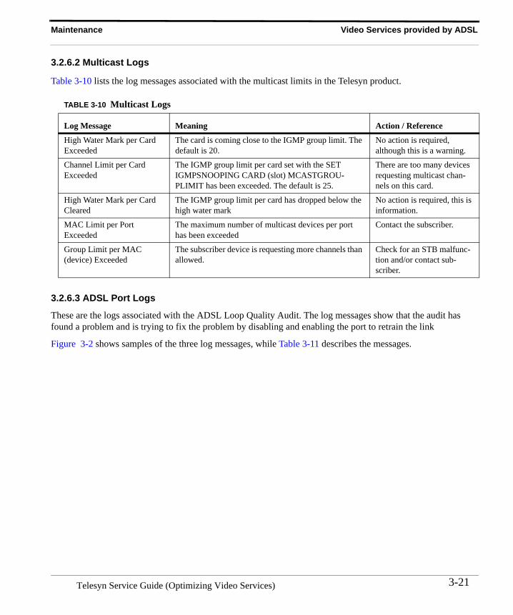
3.2.6.2 Multicast Logs
Table 3-10 lists the log messages associated with the multicast limits in the Telesyn product.
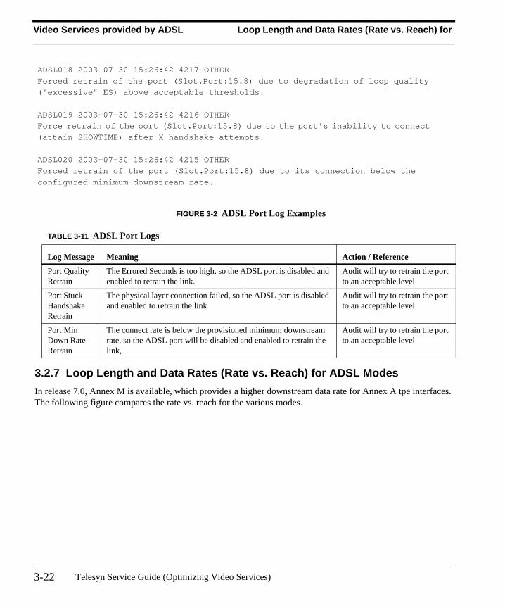
3.2.6.3 ADSL Port Logs
These are the logs associated with the ADSL Loop Quality Audit. The log messages show that the audit has found a problem and is trying to fix the problem by disabling and enabling the port to retrain the link
Figure 3-2 shows samples of the three log messages, while Table 3-11 describes the messages.
TABLE 3-10 Multicast Logs
Log Message Meaning Action / Reference
High Water Mark per Card Exceeded
The card is coming close to the IGMP group limit. The default is 20.
No action is required, although this is a warning.
Channel Limit per Card Exceeded
The IGMP group limit per card set with the SET IGMPSNOOPING CARD (slot) MCASTGROU-PLIMIT has been exceeded. The default is 25.
There are too many devices requesting multicast chan-nels on this card.
High Water Mark per Card Cleared
The IGMP group limit per card has dropped below the high water mark
No action is required, this is information.
MAC Limit per Port Exceeded
The maximum number of multicast devices per port has been exceeded
Contact the subscriber.
Group Limit per MAC (device) Exceeded
The subscriber device is requesting more channels than allowed.
Check for an STB malfunc-tion and/or contact sub-scriber.
3-21Telesyn Service Guide (Optimizing Video Services)
Video Services provided by ADSL Loop Length and Data Rates (Rate vs. Reach) for
FIGURE 3-2 ADSL Port Log Examples
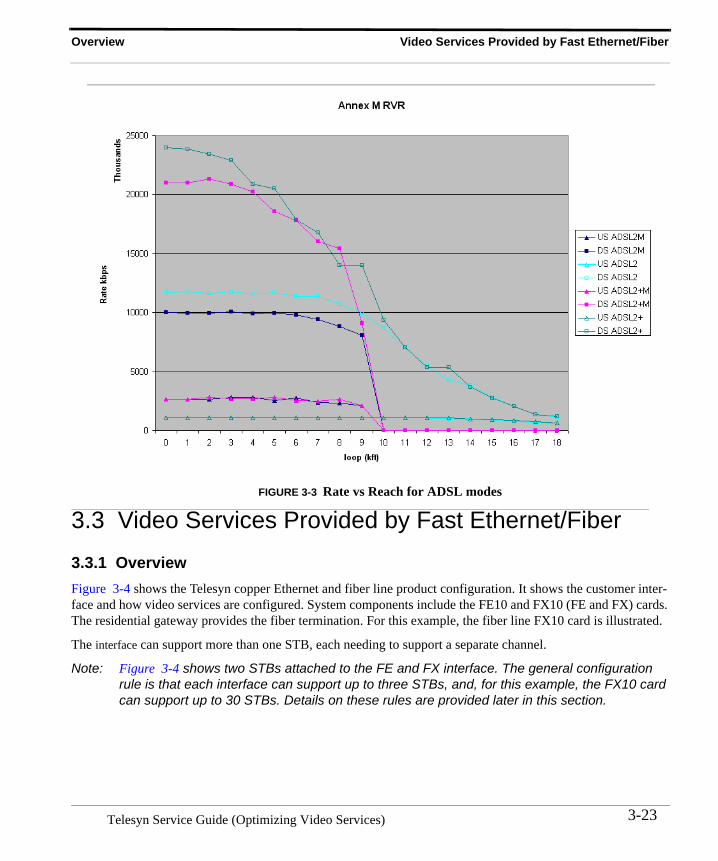
3.2.7 Loop Length and Data Rates (Rate vs. Reach) for ADSL ModesIn release 7.0, Annex M is available, which provides a higher downstream data rate for Annex A tpe interfaces. The following figure compares the rate vs. reach for the various modes.
TABLE 3-11 ADSL Port Logs
Log Message Meaning Action / Reference
Port Quality Retrain
The Errored Seconds is too high, so the ADSL port is disabled and enabled to retrain the link.
Audit will try to retrain the port to an acceptable level
Port Stuck Handshake Retrain
The physical layer connection failed, so the ADSL port is disabled and enabled to retrain the link
Audit will try to retrain the port to an acceptable level
Port Min Down Rate Retrain
The connect rate is below the provisioned minimum downstream rate, so the ADSL port will be disabled and enabled to retrain the link,
Audit will try to retrain the port to an acceptable level
ADSL018 2003-07-30 15:26:42 4217 OTHERForced retrain of the port (Slot.Port:15.8) due to degradation of loop quality ("excessive" ES) above acceptable thresholds.
ADSL019 2003-07-30 15:26:42 4216 OTHERForce retrain of the port (Slot.Port:15.8) due to the port's inability to connect (attain SHOWTIME) after X handshake attempts.
ADSL020 2003-07-30 15:26:42 4215 OTHERForced retrain of the port (Slot.Port:15.8) due to its connection below the configured minimum downstream rate.
Telesyn Service Guide (Optimizing Video Services)3-22
Overview Video Services Provided by Fast Ethernet/Fiber
FIGURE 3-3 Rate vs Reach for ADSL modes
3.3 Video Services Provided by Fast Ethernet/Fiber
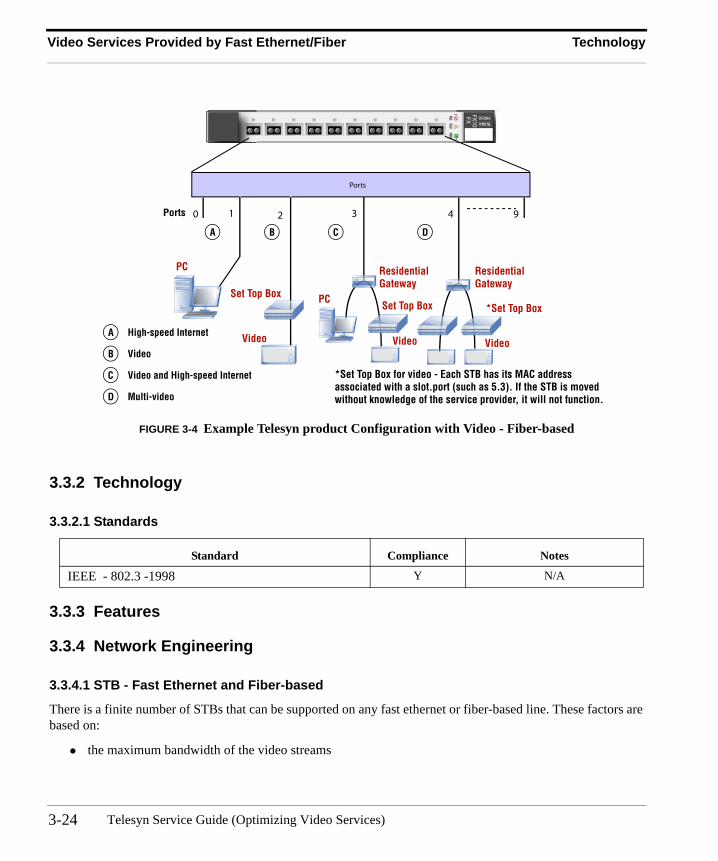
3.3.1 OverviewFigure 3-4 shows the Telesyn copper Ethernet and fiber line product configuration. It shows the customer inter-face and how video services are configured. System components include the FE10 and FX10 (FE and FX) cards. The residential gateway provides the fiber termination. For this example, the fiber line FX10 card is illustrated.
The interface can support more than one STB, each needing to support a separate channel.
Note: Figure 3-4 shows two STBs attached to the FE and FX interface. The general configuration rule is that each interface can support up to three STBs, and, for this example, the FX10 card can support up to 30 STBs. Details on these rules are provided later in this section.
3-23Telesyn Service Guide (Optimizing Video Services)
Video Services Provided by Fast Ethernet/Fiber Technology
FIGURE 3-4 Example Telesyn product Configuration with Video - Fiber-based
3.3.2 Technology
3.3.2.1 Standards
3.3.3 Features
3.3.4 Network Engineering
3.3.4.1 STB - Fast Ethernet and Fiber-based
There is a finite number of STBs that can be supported on any fast ethernet or fiber-based line. These factors are based on:
• the maximum bandwidth of the video streams
Standard Compliance Notes
IEEE - 802.3 -1998 Y N/A
PULLFAULT
INSERV
FE10 TN-100-A
TN-100-A
PULLFAULT
INSERV
FX10 TN-104-ATN-104-A
FX
Ports
0 91 2 3 4Ports
PC
A
Set Top Box
Video
B
Video
Set Top BoxPC
C
A High-speed Internet
B Video
C Video and High-speed Internet
D Multi-video
Video
*Set Top Box
D
*Set Top Box for video - Each STB has its MAC addressassociated with a slot.port (such as 5.3). If the STB is movedwithout knowledge of the service provider, it will not function.
ResidentialGateway
ResidentialGateway
Telesyn Service Guide (Optimizing Video Services)3-24
Software Engineering Video Services Provided by Fast Ethernet/Fiber
• overhead for transmitting over the line• bandwidth for Electronic Programming Guide (EPG) and emergency action channels• bandwidth for data
3.3.4.2 FE10/FX10 IGMP Video ConfigurationFor each ADSL and fiber interface, the following can be configured for the specified Telesyn:
• Three STB with Five streams per STB
3.3.5 Software Engineering
3.3.5.1 Interface Provisioning for Fast Ethernet and Fiber-based Ports
Refer to Section Provisioning Network, Service, and Control Modules and subsection ADSL Port for an overview of all attributes of these interfaces.
To provide quality video service, the service provider must perform the following tasks:
1. Correctly provision the interface.2. Monitor the interface so problems or potential problems can be noted and resolved.3. Ensure service providers have correctly configured the equipment.4. Check for faults with the physical connection(s) or equipment from the interface to the subscriber’s equip-
ment.
The first two tasks are directly related to provisioning the Telesyn product and are therefore covered both in this section and other sections of this Guide. Moreover, the Telesyn product helps with the other two tasks by provid-ing features that help determine if a problem is in a component that is not directly a part of the Telesyn product.
With these features, service providers can provide more timely customer support and ensure the subscriber line is correctly configured.
3-25Telesyn Service Guide (Optimizing Video Services)
Video Services Provided by Fast Ethernet/Fiber Software Engineering
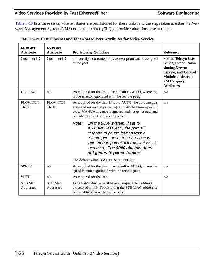
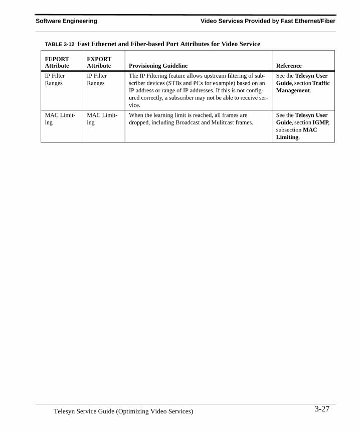
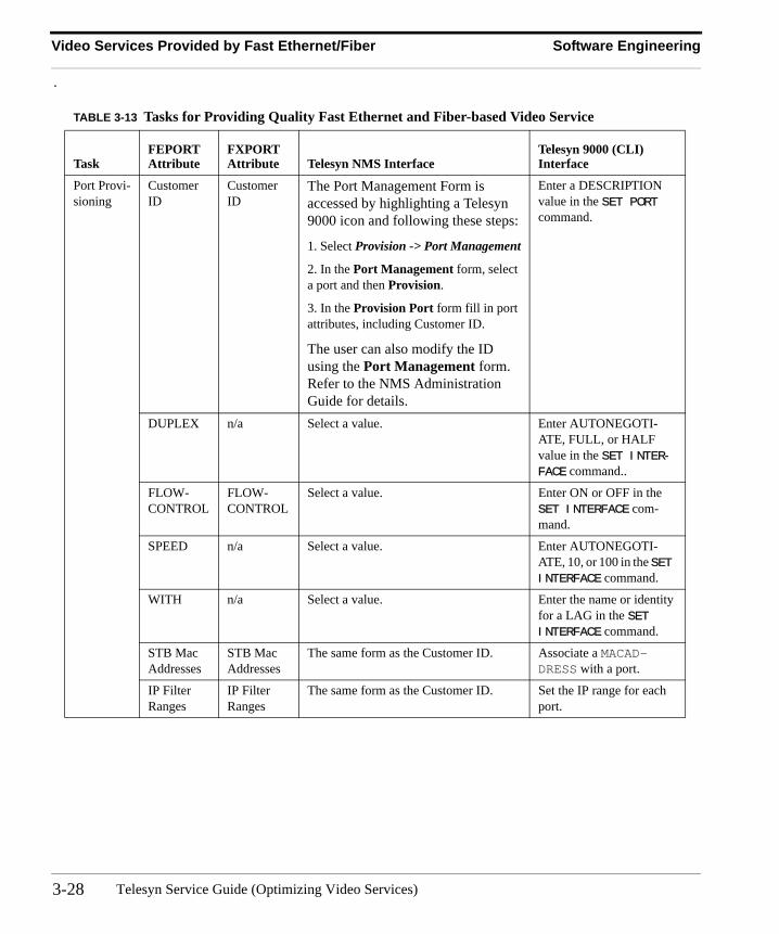
Table 3-13 lists these tasks, what attributes are provisioned for these tasks, and the steps taken at either the Net-work Management System (NMS) or local interface (CLI) to provide values for these attributes.
TABLE 3-12 Fast Ethernet and Fiber-based Port Attributes for Video Service
FEPORTAttribute
FXPORT Attribute Provisioning Guideline Reference
Customer ID Customer ID To identify a customer loop, a description can be assigned to the port
See the Telesyn User Guide, section Provi-sioning Network, Service, and Control Modules, subsection SM Category Attributes.
DUPLEX n/a As required for the line. The default is AUTO, where the mode is auto negotiated with the remote peer.
n/a
FLOWCON-TROL
FLOWCON-TROL
As required for the line. If set to AUTO, the port can gen-erate and respond to pause signals with the remote peer. If set to MANUAL, pause is ignored and not generated, and potential for packet loss is increased.
Note: On the 9000 system, if set to AUTONEGOTIATE, the port will respond to pause frames from a remote peer. If set to ON, pause is ignored and potential for packet loss is increased. The 9000 chassis does not generate pause frames.
The default value is AUTONEGOTIATE.
n/a
SPEED n/a As required for the line. The default is AUTO, where the speed is auto negotiated with the remote peer.
n/a
WITH n/a As required for the line n/a
STB Mac Addresses
STB Mac Addresses
Each IGMP device must have a unique MAC address associated with it. Provisioning the STB MAC address is required to prevent theft of service.
Telesyn Service Guide (Optimizing Video Services)3-26
Software Engineering Video Services Provided by Fast Ethernet/Fiber
IP Filter Ranges
IP Filter Ranges
The IP Filtering feature allows upstream filtering of sub-scriber devices (STBs and PCs for example) based on an IP address or range of IP addresses. If this is not config-ured correctly, a subscriber may not be able to receive ser-vice.
See the Telesyn User Guide, section Traffic Management.
MAC Limit-ing
MAC Limit-ing
When the learning limit is reached, all frames are dropped, including Broadcast and Mulitcast frames.
See the Telesyn User Guide, section IGMP, subsection MAC Limiting.
TABLE 3-12 Fast Ethernet and Fiber-based Port Attributes for Video Service
FEPORTAttribute
FXPORT Attribute Provisioning Guideline Reference
3-27Telesyn Service Guide (Optimizing Video Services)
Video Services Provided by Fast Ethernet/Fiber Software Engineering
.
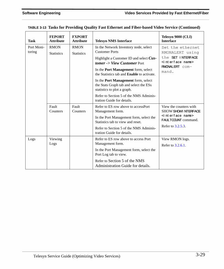
TABLE 3-13 Tasks for Providing Quality Fast Ethernet and Fiber-based Video Service
TaskFEPORTAttribute
FXPORT Attribute Telesyn NMS Interface
Telesyn 9000 (CLI) Interface
Port Provi-sioning
Customer ID
Customer ID
The Port Management Form is accessed by highlighting a Telesyn 9000 icon and following these steps:
1. Select Provision -> Port Management
2. In the Port Management form, select a port and then Provision.
3. In the Provision Port form fill in port attributes, including Customer ID.
The user can also modify the ID using the Port Management form. Refer to the NMS Administration Guide for details.
Enter a DESCRIPTION value in the SET PORT command.
DUPLEX n/a Select a value. Enter AUTONEGOTI-ATE, FULL, or HALF value in the SET INTER-FACE command..
FLOW-CONTROL
FLOW-CONTROL
Select a value. Enter ON or OFF in the SET INTERFACE com-mand.
SPEED n/a Select a value. Enter AUTONEGOTI-ATE, 10, or 100 in the SET INTERFACE command.
WITH n/a Select a value. Enter the name or identity for a LAG in the SET INTERFACE command.
STB Mac Addresses
STB Mac Addresses
The same form as the Customer ID. Associate a MACAD-DRESS with a port.
IP Filter Ranges
IP Filter Ranges
The same form as the Customer ID. Set the IP range for each port.
Telesyn Service Guide (Optimizing Video Services)3-28
Software Engineering Video Services Provided by Fast Ethernet/Fiber
Port Moni-toring
RMON
Statistics
RMON
Statistics
In the Network Inventory node, select Customer Ports
Highlight a Customer ID and select Cus-tomer -> View Customer Port
In the Port Management form, select the Statistics tab and Enable to activate.
In the Port Management form, select the Stats Graph tab and select the ESs statistics to plot a graph.
Refer to Section 5 of the NMS Adminis-tration Guide for details.
Set the ethernet RMONALERT using the SET INTERFACE <interface name>
RMONALERT com-mand.
Fault Counters
Fault Counters
Refer to ES row above to accessPort Management form.
In the Port Management form, select the Statistics tab to view and reset.
Refer to Section 5 of the NMS Adminis-tration Guide for details.
View the counters with SHOW SHOW INTERFACE <interface name>
FAULTCOUNT command.
Refer to 3.2.5.3.
Logs Viewing Logs
Refer to ES row above to access Port Management form.
In the Port Management form, select the Port Log tab to view.
Refer to Section 5 of the NMS Administration Guide for details.
View RMON logs.
Refer to 3.2.6.1.
TABLE 3-13 Tasks for Providing Quality Fast Ethernet and Fiber-based Video Service (Continued)
TaskFEPORTAttribute
FXPORT Attribute Telesyn NMS Interface
Telesyn 9000 (CLI) Interface
3-29Telesyn Service Guide (Optimizing Video Services)
Video Services Provided by Fast Ethernet/Fiber Software Engineering
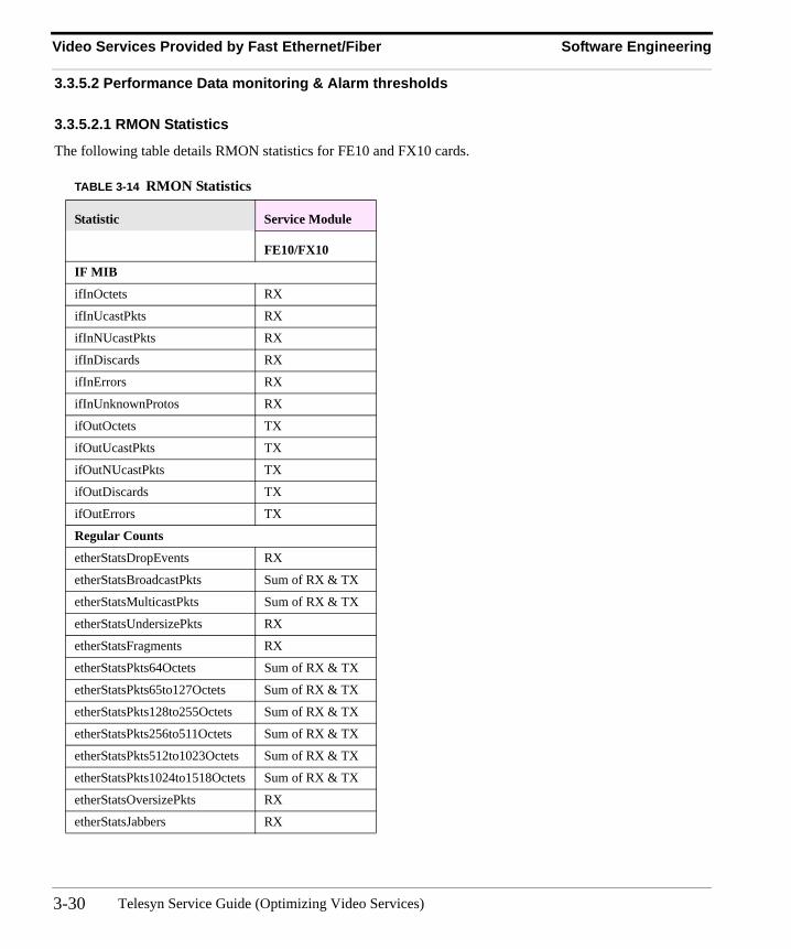
3.3.5.2 Performance Data monitoring & Alarm thresholds
3.3.5.2.1 RMON Statistics
The following table details RMON statistics for FE10 and FX10 cards.
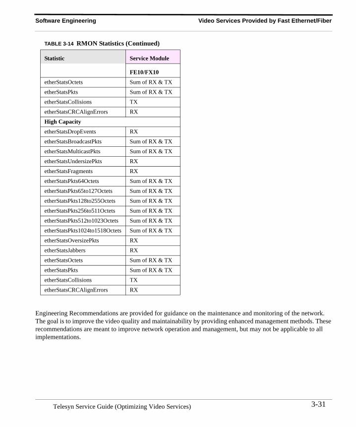
TABLE 3-14 RMON Statistics
Statistic Service Module
FE10/FX10
IF MIB
ifInOctets RX
ifInUcastPkts RX
ifInNUcastPkts RX
ifInDiscards RX
ifInErrors RX
ifInUnknownProtos RX
ifOutOctets TX
ifOutUcastPkts TX
ifOutNUcastPkts TX
ifOutDiscards TX
ifOutErrors TX
Regular Counts
etherStatsDropEvents RX
etherStatsBroadcastPkts Sum of RX & TX
etherStatsMulticastPkts Sum of RX & TX
etherStatsUndersizePkts RX
etherStatsFragments RX
etherStatsPkts64Octets Sum of RX & TX
etherStatsPkts65to127Octets Sum of RX & TX
etherStatsPkts128to255Octets Sum of RX & TX
etherStatsPkts256to511Octets Sum of RX & TX
etherStatsPkts512to1023Octets Sum of RX & TX
etherStatsPkts1024to1518Octets Sum of RX & TX
etherStatsOversizePkts RX
etherStatsJabbers RX
Telesyn Service Guide (Optimizing Video Services)3-30
Software Engineering Video Services Provided by Fast Ethernet/Fiber
Engineering Recommendations are provided for guidance on the maintenance and monitoring of the network. The goal is to improve the video quality and maintainability by providing enhanced management methods. These recommendations are meant to improve network operation and management, but may not be applicable to all implementations.
etherStatsOctets Sum of RX & TX
etherStatsPkts Sum of RX & TX
etherStatsCollisions TX
etherStatsCRCAlignErrors RX
High Capacity
etherStatsDropEvents RX
etherStatsBroadcastPkts Sum of RX & TX
etherStatsMulticastPkts Sum of RX & TX
etherStatsUndersizePkts RX
etherStatsFragments RX
etherStatsPkts64Octets Sum of RX & TX
etherStatsPkts65to127Octets Sum of RX & TX
etherStatsPkts128to255Octets Sum of RX & TX
etherStatsPkts256to511Octets Sum of RX & TX
etherStatsPkts512to1023Octets Sum of RX & TX
etherStatsPkts1024to1518Octets Sum of RX & TX
etherStatsOversizePkts RX
etherStatsJabbers RX
etherStatsOctets Sum of RX & TX
etherStatsPkts Sum of RX & TX
etherStatsCollisions TX
etherStatsCRCAlignErrors RX
TABLE 3-14 RMON Statistics (Continued)
Statistic Service Module
FE10/FX10
3-31Telesyn Service Guide (Optimizing Video Services)
Video Services Provided by Fast Ethernet/Fiber Software Engineering
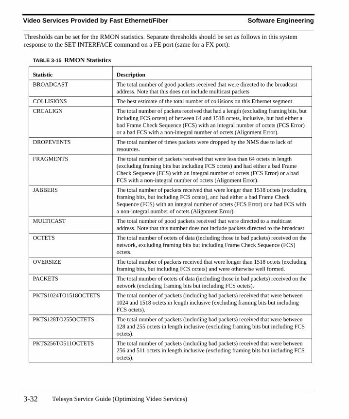
Thresholds can be set for the RMON statistics. Separate thresholds should be set as follows in this system response to the SET INTERFACE command on a FE port (same for a FX port):
TABLE 3-15 RMON Statistics
Statistic Description
BROADCAST The total number of good packets received that were directed to the broadcast address. Note that this does not include multicast packets
COLLISIONS The best estimate of the total number of collisions on this Ethernet segment
CRCALIGN The total number of packets received that had a length (excluding framing bits, but including FCS octets) of between 64 and 1518 octets, inclusive, but had either a bad Frame Check Sequence (FCS) with an integral number of octets (FCS Error) or a bad FCS with a non-integral number of octets (Alignment Error).
DROPEVENTS The total number of times packets were dropped by the NMS due to lack of resources.
FRAGMENTS The total number of packets received that were less than 64 octets in length (excluding framing bits but including FCS octets) and had either a bad Frame Check Sequence (FCS) with an integral number of octets (FCS Error) or a bad FCS with a non-integral number of octets (Alignment Error).
JABBERS The total number of packets received that were longer than 1518 octets (excluding framing bits, but including FCS octets), and had either a bad Frame Check Sequence (FCS) with an integral number of octets (FCS Error) or a bad FCS with a non-integral number of octets (Alignment Error).
MULTICAST The total number of good packets received that were directed to a multicast address. Note that this number does not include packets directed to the broadcast
OCTETS The total number of octets of data (including those in bad packets) received on the network, excluding framing bits but including Frame Check Sequence (FCS) octets.
OVERSIZE The total number of packets received that were longer than 1518 octets (excluding framing bits, but including FCS octets) and were otherwise well formed.
PACKETS The total number of octets of data (including those in bad packets) received on the network (excluding framing bits but including FCS octets).
PKTS1024TO1518OCTETS The total number of packets (including bad packets) received that were between 1024 and 1518 octets in length inclusive (excluding framing bits but including FCS octets).
PKTS128TO255OCTETS The total number of packets (including bad packets) received that were between 128 and 255 octets in length inclusive (excluding framing bits but including FCS octets).
PKTS256TO511OCTETS The total number of packets (including bad packets) received that were between 256 and 511 octets in length inclusive (excluding framing bits but including FCS octets).
Telesyn Service Guide (Optimizing Video Services)3-32
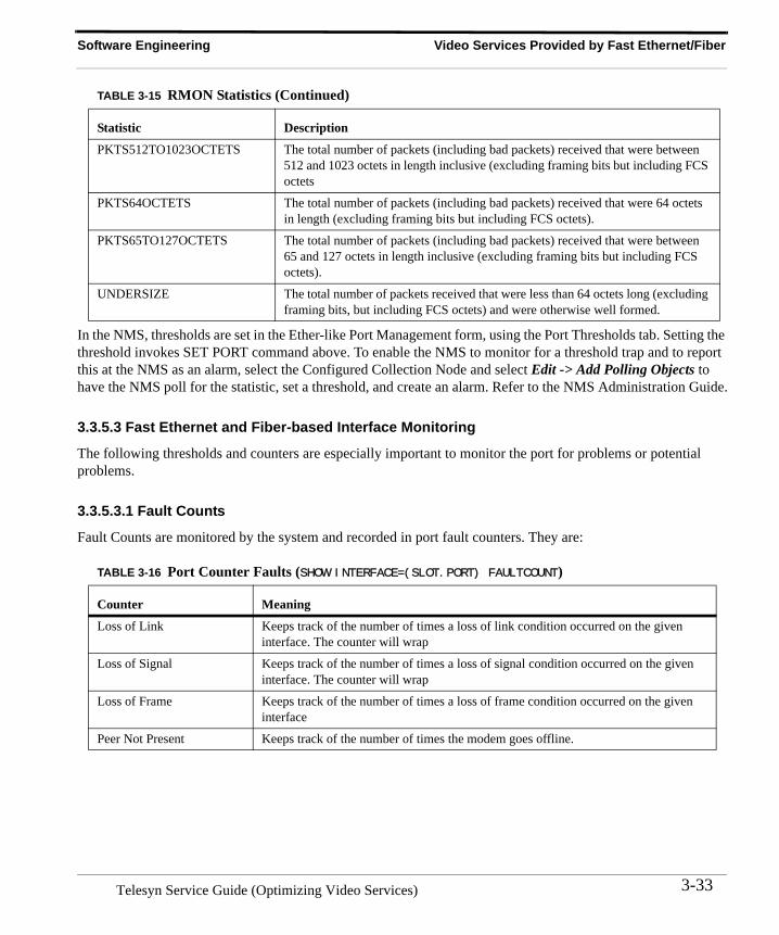
Software Engineering Video Services Provided by Fast Ethernet/Fiber
In the NMS, thresholds are set in the Ether-like Port Management form, using the Port Thresholds tab. Setting the threshold invokes SET PORT command above. To enable the NMS to monitor for a threshold trap and to report this at the NMS as an alarm, select the Configured Collection Node and select Edit -> Add Polling Objects to have the NMS poll for the statistic, set a threshold, and create an alarm. Refer to the NMS Administration Guide.
3.3.5.3 Fast Ethernet and Fiber-based Interface Monitoring
The following thresholds and counters are especially important to monitor the port for problems or potential problems.
3.3.5.3.1 Fault Counts
Fault Counts are monitored by the system and recorded in port fault counters. They are:
PKTS512TO1023OCTETS The total number of packets (including bad packets) received that were between 512 and 1023 octets in length inclusive (excluding framing bits but including FCS octets
PKTS64OCTETS The total number of packets (including bad packets) received that were 64 octets in length (excluding framing bits but including FCS octets).
PKTS65TO127OCTETS The total number of packets (including bad packets) received that were between 65 and 127 octets in length inclusive (excluding framing bits but including FCS octets).
UNDERSIZE The total number of packets received that were less than 64 octets long (excluding framing bits, but including FCS octets) and were otherwise well formed.
TABLE 3-16 Port Counter Faults (SHOW INTERFACE=(SLOT.PORT) FAULTCOUNT)
Counter Meaning
Loss of Link Keeps track of the number of times a loss of link condition occurred on the given interface. The counter will wrap
Loss of Signal Keeps track of the number of times a loss of signal condition occurred on the given interface. The counter will wrap
Loss of Frame Keeps track of the number of times a loss of frame condition occurred on the given interface
Peer Not Present Keeps track of the number of times the modem goes offline.
TABLE 3-15 RMON Statistics (Continued)
Statistic Description
3-33Telesyn Service Guide (Optimizing Video Services)
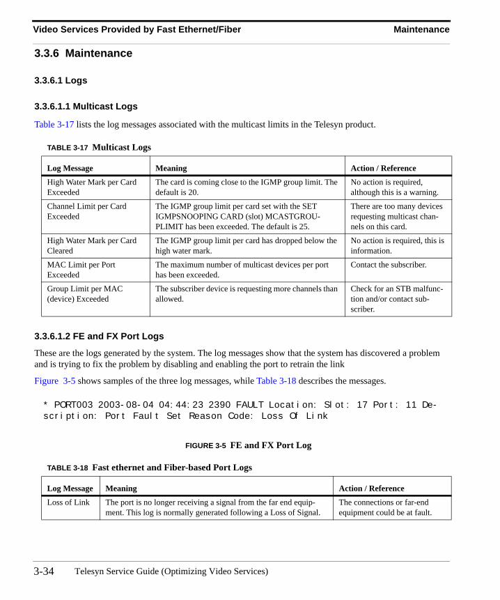
Video Services Provided by Fast Ethernet/Fiber Maintenance
3.3.6 Maintenance
3.3.6.1 Logs
3.3.6.1.1 Multicast Logs
Table 3-17 lists the log messages associated with the multicast limits in the Telesyn product.
3.3.6.1.2 FE and FX Port Logs
These are the logs generated by the system. The log messages show that the system has discovered a problem and is trying to fix the problem by disabling and enabling the port to retrain the link
Figure 3-5 shows samples of the three log messages, while Table 3-18 describes the messages.
FIGURE 3-5 FE and FX Port Log
TABLE 3-17 Multicast Logs
Log Message Meaning Action / Reference
High Water Mark per Card Exceeded
The card is coming close to the IGMP group limit. The default is 20.
No action is required, although this is a warning.
Channel Limit per Card Exceeded
The IGMP group limit per card set with the SET IGMPSNOOPING CARD (slot) MCASTGROU-PLIMIT has been exceeded. The default is 25.
There are too many devices requesting multicast chan-nels on this card.
High Water Mark per Card Cleared
The IGMP group limit per card has dropped below the high water mark.
No action is required, this is information.
MAC Limit per Port Exceeded
The maximum number of multicast devices per port has been exceeded.
Contact the subscriber.
Group Limit per MAC (device) Exceeded
The subscriber device is requesting more channels than allowed.
Check for an STB malfunc-tion and/or contact sub-scriber.
TABLE 3-18 Fast ethernet and Fiber-based Port Logs
Log Message Meaning Action / Reference
Loss of Link The port is no longer receiving a signal from the far end equip-ment. This log is normally generated following a Loss of Signal.
The connections or far-end equipment could be at fault.
* PORT003 2003-08-04 04:44:23 2390 FAULT Location: Slot: 17 Port: 11 De-scription: Port Fault Set Reason Code: Loss Of Link
Telesyn Service Guide (Optimizing Video Services)3-34
4. Optimizing Voice Services
4.1 OverviewVoice service can be provided with the following configurations:
• POTS with a call agent using the POTS24 card
In this configuration, the POTS24 card supports VoIP using Media Gateway Control Protocol (MGCP) as the call control protocol to the network gateway as defined in the Line Control Signalling (LCS) architecture. The Telesyn POTS24 card transforms analog POTS calls into IP packets and forward these packets onto an Ether-net network. The network gateway accepts these packets and forwards them to a Class 5 switch via GR-303 trunks.
Furthermore, the POTS24 supports the use of RFC2833 to signal Robbed Bit Signalling (RBS) events when requested by the Internet Protocol Digital Terminal (IPDT, the LCS representation of the MGC or call agent). Line signaling events are sent to the IPDT by the POTS24 for on-hook and off-hook events detected on its lines. Likewise, the IPDT will signal RBS events to the POTS24 in order to condition its lines to facilitate call management (for example, external ringback)
to connect to a phone (or modem or fax machine), and is embedded in ethernet.
• Derived Voice
In this configuration, the Residential Gateway provides the same functionality as the POTS24 card and Tele-syn device; it can then connect to a Telesyn device or directly to the network. The connection to the network gateway over GR-303 trunks is the same.
In this section, each configuration is described separately.
4.2 POTS Only with Call Agent (POTS24 Card)
4.2.1 OverviewFigure 4-1 shows the physical configuration of Voice call processing using the POTS24 card and Call Agent. The analog loop is converted to and ethernet uplink and then connected with the network.
Note: This figure also shows that the POTS24 card can be used for data services, such as a pc or fax, since it can connect to a dial-up analog modem.
4-1 Telesyn Service Guide (Optimizing Voice Services)
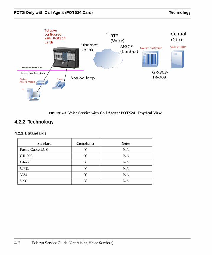
POTS Only with Call Agent (POTS24 Card) Technology
FIGURE 4-1 Voice Service with Call Agent / POTS24 - Physical View
4.2.2 Technology
4.2.2.1 Standards
Standard Compliance Notes
PacketCable LCS Y N/A
GR-909 Y N/A
GR-57 Y N/A
G.711 Y N/A
V.34 Y N/A
V.90 Y N/A
Telesyn MAPconfiguredwith POTS24Cards
Subscriber Premises
Provider Premises
Gateway / Softswitch
PC
Class 5 Switch
RTP(Voice)
MGCP(Control)
GR-303/TR-008Analog loop
EthernetUplink
CentralOffice
PhoneDial-upAnalog Modem
‘
Telesyn Service Guide (Optimizing Voice Services)4-2
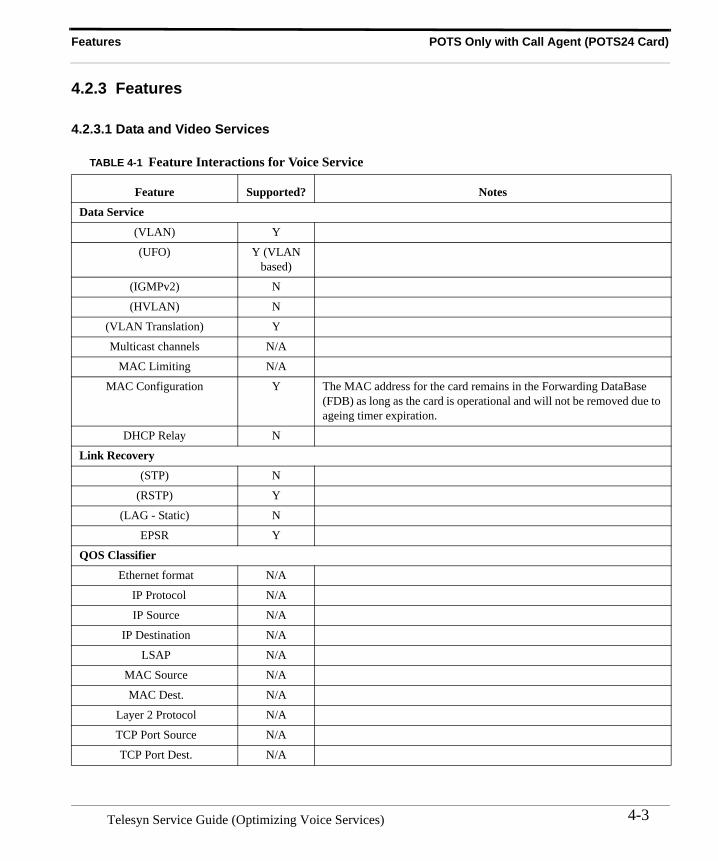
Features POTS Only with Call Agent (POTS24 Card)
4.2.3 Features
4.2.3.1 Data and Video Services
TABLE 4-1 Feature Interactions for Voice Service
Feature Supported? Notes
Data Service
(VLAN) Y
(UFO) Y (VLAN based)
(IGMPv2) N
(HVLAN) N
(VLAN Translation) Y
Multicast channels N/A
MAC Limiting N/A
MAC Configuration Y The MAC address for the card remains in the Forwarding DataBase (FDB) as long as the card is operational and will not be removed due to ageing timer expiration.
DHCP Relay N
Link Recovery
(STP) N
(RSTP) Y
(LAG - Static) N
EPSR Y
QOS Classifier
Ethernet format N/A
IP Protocol N/A
IP Source N/A
IP Destination N/A
LSAP N/A
MAC Source N/A
MAC Dest. N/A
Layer 2 Protocol N/A
TCP Port Source N/A
TCP Port Dest. N/A
4-3Telesyn Service Guide (Optimizing Voice Services)
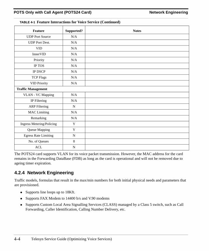
POTS Only with Call Agent (POTS24 Card) Network Engineering
The POTS24 card supports VLAN for its voice packet transmission. However, the MAC address for the card remains in the Forwarding DataBase (FDB) as long as the card is operational and will not be removed due to ageing timer expiration.
4.2.4 Network EngineeringTraffic models, formulas that result in the max/min numbers for both initial physical needs and parameters that are provisioned.
• Supports line loops up to 18Kft.• Supports FAX Modem to 14400 b/s and V.90 modems• Supports Custom Local Area Signalling Services (CLASS) managed by a Class 5 switch, such as Call
Forwarding, Caller Identification, Calling Number Delivery, etc.
UDP Port Source N/A
UDP Port Dest. N/A
VID N/A
InnerVID N/A
Priority N/A
IP TOS N/A
IP DSCP N/A
TCP Flags N/A
VID Priority N/A
Traffic Management
VLAN - VC Mapping N/A
IP Filtering N/A
ARP Filtering N
MAC Limiting N/A
Remarking N/A
Ingress Metering/Policing Y
Queue Mapping Y
Egress Rate Limiting N
No. of Queues 8
ACL N
TABLE 4-1 Feature Interactions for Voice Service (Continued)
Feature Supported? Notes
Telesyn Service Guide (Optimizing Voice Services)4-4
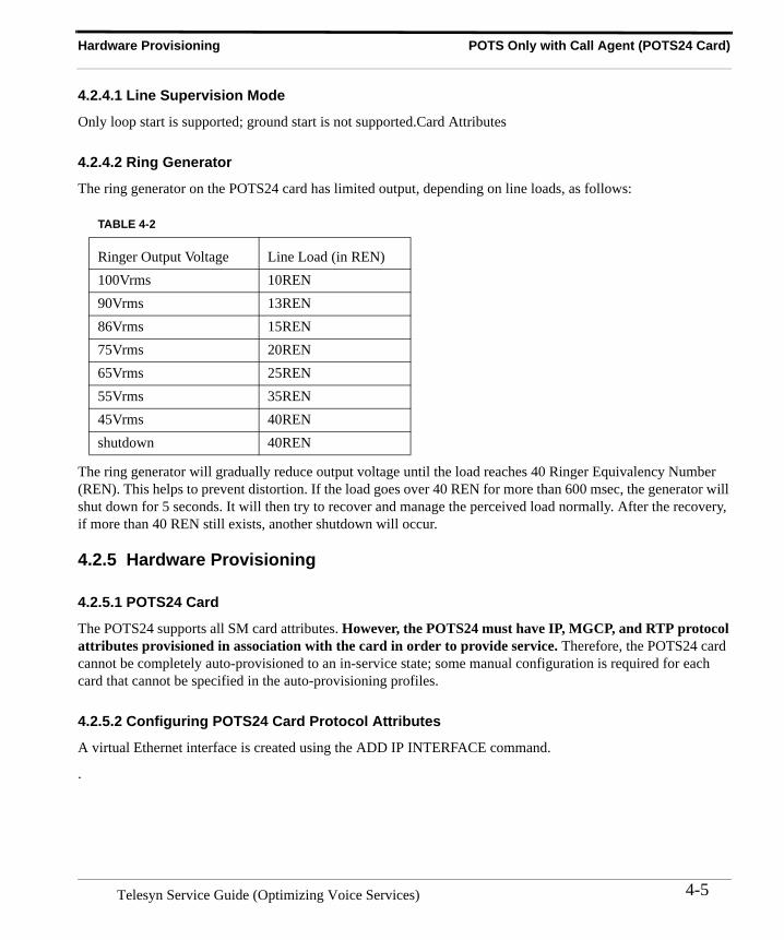
Hardware Provisioning POTS Only with Call Agent (POTS24 Card)
4.2.4.1 Line Supervision Mode
Only loop start is supported; ground start is not supported.Card Attributes
4.2.4.2 Ring Generator
The ring generator on the POTS24 card has limited output, depending on line loads, as follows:
The ring generator will gradually reduce output voltage until the load reaches 40 Ringer Equivalency Number (REN). This helps to prevent distortion. If the load goes over 40 REN for more than 600 msec, the generator will shut down for 5 seconds. It will then try to recover and manage the perceived load normally. After the recovery, if more than 40 REN still exists, another shutdown will occur.
4.2.5 Hardware Provisioning
4.2.5.1 POTS24 Card
The POTS24 supports all SM card attributes. However, the POTS24 must have IP, MGCP, and RTP protocol attributes provisioned in association with the card in order to provide service. Therefore, the POTS24 card cannot be completely auto-provisioned to an in-service state; some manual configuration is required for each card that cannot be specified in the auto-provisioning profiles.
4.2.5.2 Configuring POTS24 Card Protocol Attributes
A virtual Ethernet interface is created using the ADD IP INTERFACE command.
.
TABLE 4-2
Ringer Output Voltage Line Load (in REN)100Vrms 10REN90Vrms 13REN86Vrms 15REN75Vrms 20REN65Vrms 25REN55Vrms 35REN45Vrms 40RENshutdown 40REN
4-5Telesyn Service Guide (Optimizing Voice Services)
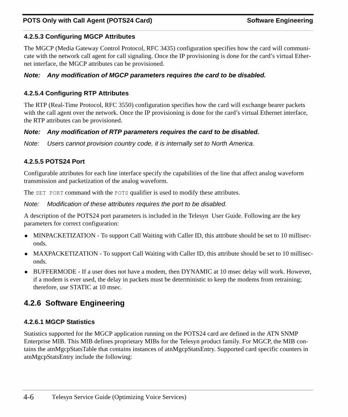
POTS Only with Call Agent (POTS24 Card) Software Engineering
4.2.5.3 Configuring MGCP Attributes
The MGCP (Media Gateway Control Protocol, RFC 3435) configuration specifies how the card will communi-cate with the network call agent for call signaling. Once the IP provisioning is done for the card’s virtual Ether-net interface, the MGCP attributes can be provisioned.
Note: Any modification of MGCP parameters requires the card to be disabled.
4.2.5.4 Configuring RTP Attributes
The RTP (Real-Time Protocol, RFC 3550) configuration specifies how the card will exchange bearer packets with the call agent over the network. Once the IP provisioning is done for the card’s virtual Ethernet interface, the RTP attributes can be provisioned.
Note: Any modification of RTP parameters requires the card to be disabled.
Note: Users cannot provision country code, it is internally set to North America.
4.2.5.5 POTS24 Port
Configurable attributes for each line interface specify the capabilities of the line that affect analog waveform transmission and packetization of the analog waveform.
The SET PORT command with the POTS qualifier is used to modify these attributes.
Note: Modification of these attributes requires the port to be disabled.
A description of the POTS24 port parameters is included in the Telesyn User Guide. Following are the key parameters for correct configuration:
• MINPACKETIZATION - To support Call Waiting with Caller ID, this attribute should be set to 10 millisec-onds.
• MAXPACKETIZATION - To support Call Waiting with Caller ID, this attribute should be set to 10 millisec-onds.
• BUFFERMODE - If a user does not have a modem, then DYNAMIC at 10 msec delay will work. However, if a modem is ever used, the delay in packets must be deterministic to keep the modems from retraining; therefore, use STATIC at 10 msec.
4.2.6 Software Engineering
4.2.6.1 MGCP Statistics
Statistics supported for the MGCP application running on the POTS24 card are defined in the ATN SNMP Enterprise MIB. This MIB defines proprietary MIBs for the Telesyn product family. For MGCP, the MIB con-tains the atnMgcpStatsTable that contains instances of atnMgcpStatsEntry. Supported card specific counters in atnMgcpStatsEntry include the following:
Telesyn Service Guide (Optimizing Voice Services)4-6
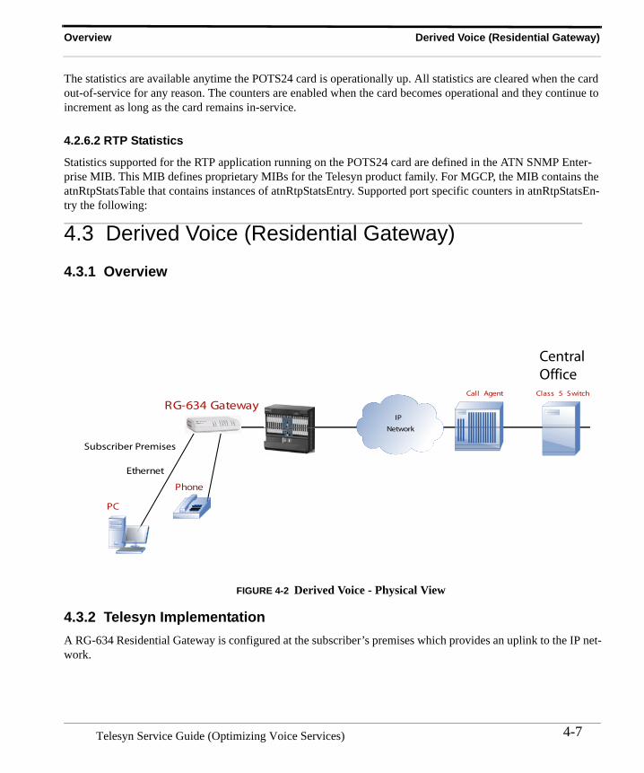
Overview Derived Voice (Residential Gateway)
The statistics are available anytime the POTS24 card is operationally up. All statistics are cleared when the card out-of-service for any reason. The counters are enabled when the card becomes operational and they continue to increment as long as the card remains in-service.
4.2.6.2 RTP Statistics
Statistics supported for the RTP application running on the POTS24 card are defined in the ATN SNMP Enter-prise MIB. This MIB defines proprietary MIBs for the Telesyn product family. For MGCP, the MIB contains the atnRtpStatsTable that contains instances of atnRtpStatsEntry. Supported port specific counters in atnRtpStatsEn-try the following:
4.3 Derived Voice (Residential Gateway)
4.3.1 Overview
FIGURE 4-2 Derived Voice - Physical View
4.3.2 Telesyn ImplementationA RG-634 Residential Gateway is configured at the subscriber’s premises which provides an uplink to the IP net-work.
RG-634
Subscriber Premises
Call Agent
PC
Class 5 Switch
CentralOffice
Phone
IP
Network
Ethernet
Gateway
4-7Telesyn Service Guide (Optimizing Voice Services)

Derived Voice (Residential Gateway) Telesyn Implementation
Telesyn Service Guide (Optimizing Voice Services)4-8
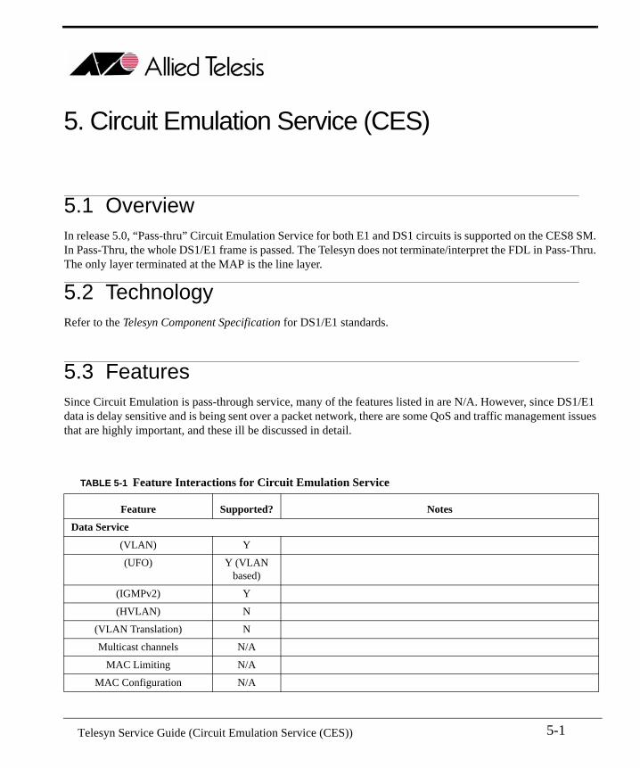
5. Circuit Emulation Service (CES)
5.1 Overview In release 5.0, “Pass-thru” Circuit Emulation Service for both E1 and DS1 circuits is supported on the CES8 SM. In Pass-Thru, the whole DS1/E1 frame is passed. The Telesyn does not terminate/interpret the FDL in Pass-Thru. The only layer terminated at the MAP is the line layer.
5.2 TechnologyRefer to the Telesyn Component Specification for DS1/E1 standards.
5.3 FeaturesSince Circuit Emulation is pass-through service, many of the features listed in are N/A. However, since DS1/E1 data is delay sensitive and is being sent over a packet network, there are some QoS and traffic management issues that are highly important, and these ill be discussed in detail.
TABLE 5-1 Feature Interactions for Circuit Emulation Service
Feature Supported? Notes
Data Service
(VLAN) Y
(UFO) Y (VLAN based)
(IGMPv2) Y
(HVLAN) N
(VLAN Translation) N
Multicast channels N/A
MAC Limiting N/A
MAC Configuration N/A
5-1 Telesyn Service Guide (Circuit Emulation Service (CES))
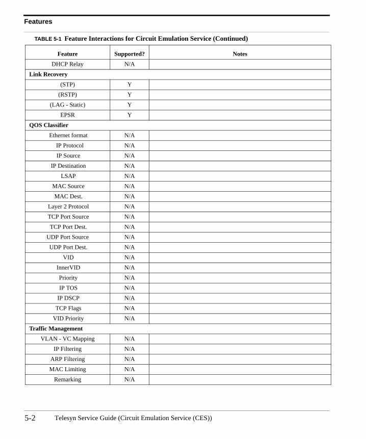
Features
DHCP Relay N/A
Link Recovery
(STP) Y
(RSTP) Y
(LAG - Static) Y
EPSR Y
QOS Classifier
Ethernet format N/A
IP Protocol N/A
IP Source N/A
IP Destination N/A
LSAP N/A
MAC Source N/A
MAC Dest. N/A
Layer 2 Protocol N/A
TCP Port Source N/A
TCP Port Dest. N/A
UDP Port Source N/A
UDP Port Dest. N/A
VID N/A
InnerVID N/A
Priority N/A
IP TOS N/A
IP DSCP N/A
TCP Flags N/A
VID Priority N/A
Traffic Management
VLAN - VC Mapping N/A
IP Filtering N/A
ARP Filtering N/A
MAC Limiting N/A
Remarking N/A
TABLE 5-1 Feature Interactions for Circuit Emulation Service (Continued)
Feature Supported? Notes
Telesyn Service Guide (Circuit Emulation Service (CES))5-2
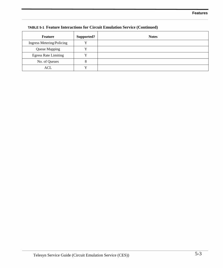
Features
Ingress Metering/Policing Y
Queue Mapping Y
Egress Rate Limiting Y
No. of Queues 8
ACL Y
TABLE 5-1 Feature Interactions for Circuit Emulation Service (Continued)
Feature Supported? Notes
5-3Telesyn Service Guide (Circuit Emulation Service (CES))
Network Engineering Packet Network Considerations
5.4 Network Engineering
5.4.1 Packet Network ConsiderationsTransport robustness is important since many characteristics of packet networks are not compatible to constant bit rate services. Packet network congestion, blocking, QoS prioritization, and multiple paths with varying latency, can lead to:
• jitter• lost packets• duplicate packets• packets out of sequence.
All of these error conditions must engineered into the CES8 configuration; some of these are done automatically by the card, while some are done though configurable parameters.
5.4.1.1 Packet Size
Packet size is directly related to the number of bytes taken from a T1 bit stream to create a packet for the pseudo span. This is user configurable and can range from 1 byte to 1488 bytes. (Refer to the Telesyn User Guide for details.)
Increasing the number of bytes per packet increases end to end latency, and thus adds delay in the TDM circuit. For data applications such as Frame Relay, latency does not significantly degrade the service. However for voice applications, sufficient amounts of delay can result in the need for echo cancellation.
At the other extreme, lower numbers of bytes per packet decrease transport efficiency by increasing the percent-age of overhead bytes associated with the packet. Setting the number of bytes per packet too low doesn’t provide enough bytes to fill the minimum Ethernet frame of 64 bytes, causing the packet to be filled with dummy infor-mation and therefore wasting packet bandwidth.
show the relationship of NUMBYTES and the bandwidth/jitter values.
5.4.1.2 Packet Delay Variation
TDM-based data operates at a constant bit rate. When converting from packet to T1, the CES8 must have a queued packet to “play out”. It cannot wait for a packet to arrive without causing errors in the T1. Unfortunately, transit time across a packet network varies from packet to packet. These variations, or jitter, in the arrival time of the incoming packets and are commonly referred to as Packet Delay Variation (PDV). PDV is a parameter that is measured in milliseconds. PDV has many origins; multiple routes with different transit times, switch con-gestion, mixed packet sizes, contention with traffic with marked for higher QoS, and router loading.
Generally, the more switching or routing nodes in the pseudo span path, the greater the PDV. In order to com-pensate for PDV, the CES8 must buffer enough packets to ensure there that another packet has arrived before the
Telesyn Service Guide (Circuit Emulation Service (CES))5-4
Packet Network Considerations Network Engineering
current packet has been played out. The CES8 provides buffers that can be configured to absorb up to 60ms of PDV. Increasing the depth of these buffers adds latency and thus delay to the T1.
As mentioned above in the discussion on packet size, latency may not degrade some data services but voice ser-vices may require echo cancellation to handle excessive delays.
5.4.1.3 End-to-End Latency
Many services carried over T1 are delay sensitive. For example, in voice applications end to end transport latency greater than 25ms generally requires the use of echo cancellers to remove audible reflections from far end 4 to2 wire hybrid circuits. Therefore it is often important to understand the total end to end transport delay when engi-neering a T1 over Ethernet circuit.
Calculations of end to end latency must include the following:
1. Packet size - The number of bytes from the T1 stream that are used to form the Ethernet packet. 2. Switch transit delay - The delay incurred as a packet is switched or routed through nodes in the Ethernet net-
work.3. PDV Buffering - The depth of the jitter buffer on the DCEI8 adds to the end to end delay.
The total latency is determined by adding the contribution of each the factors above. For example, in an EPSR configuration the end to end delay varies depending on which direction traffic is circulating on the ring.
5-5Telesyn Service Guide (Circuit Emulation Service (CES))
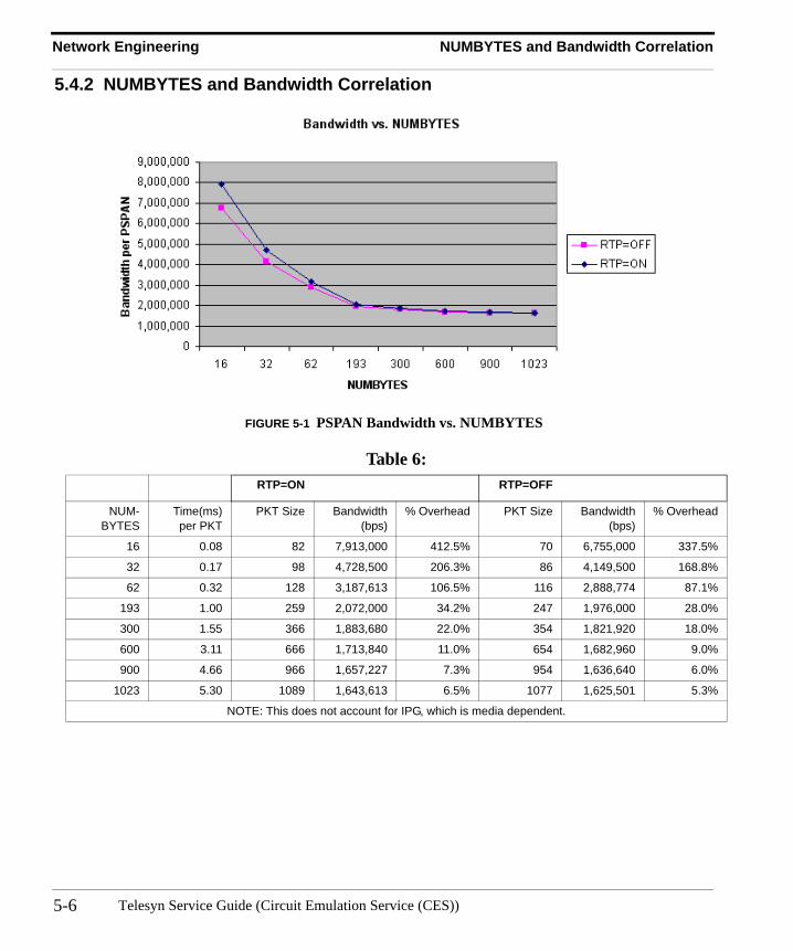
Network Engineering NUMBYTES and Bandwidth Correlation
5.4.2 NUMBYTES and Bandwidth Correlation
FIGURE 5-1 PSPAN Bandwidth vs. NUMBYTES
Table 6: RTP=ON RTP=OFF
NUM-BYTES
Time(ms)per PKT
PKT Size Bandwidth(bps)
% Overhead PKT Size Bandwidth(bps)
% Overhead
16 0.08 82 7,913,000 412.5% 70 6,755,000 337.5%
32 0.17 98 4,728,500 206.3% 86 4,149,500 168.8%
62 0.32 128 3,187,613 106.5% 116 2,888,774 87.1%
193 1.00 259 2,072,000 34.2% 247 1,976,000 28.0%
300 1.55 366 1,883,680 22.0% 354 1,821,920 18.0%
600 3.11 666 1,713,840 11.0% 654 1,682,960 9.0%
900 4.66 966 1,657,227 7.3% 954 1,636,640 6.0%
1023 5.30 1089 1,643,613 6.5% 1077 1,625,501 5.3%
NOTE: This does not account for IPG, which is media dependent.
Telesyn Service Guide (Circuit Emulation Service (CES))5-6
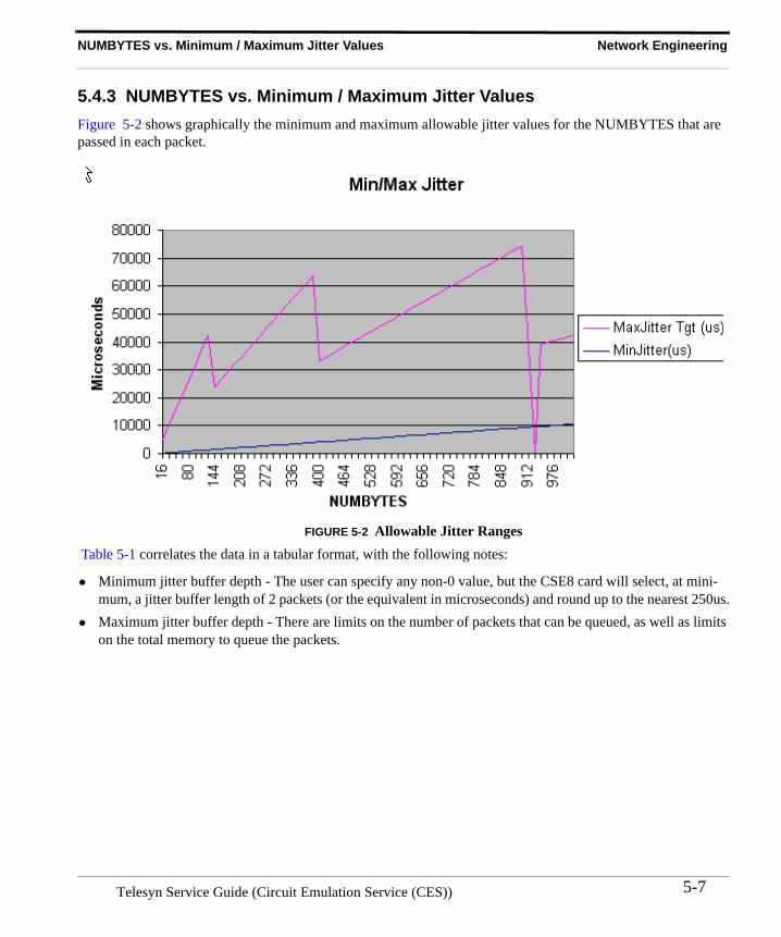
NUMBYTES vs. Minimum / Maximum Jitter Values Network Engineering
5.4.3 NUMBYTES vs. Minimum / Maximum Jitter ValuesFigure 5-2 shows graphically the minimum and maximum allowable jitter values for the NUMBYTES that are passed in each packet.
FIGURE 5-2 Allowable Jitter Ranges Table 5-1 correlates the data in a tabular format, with the following notes:
• Minimum jitter buffer depth - The user can specify any non-0 value, but the CSE8 card will select, at mini-mum, a jitter buffer length of 2 packets (or the equivalent in microseconds) and round up to the nearest 250us.
• Maximum jitter buffer depth - There are limits on the number of packets that can be queued, as well as limits on the total memory to queue the packets.
5-7Telesyn Service Guide (Circuit Emulation Service (CES))
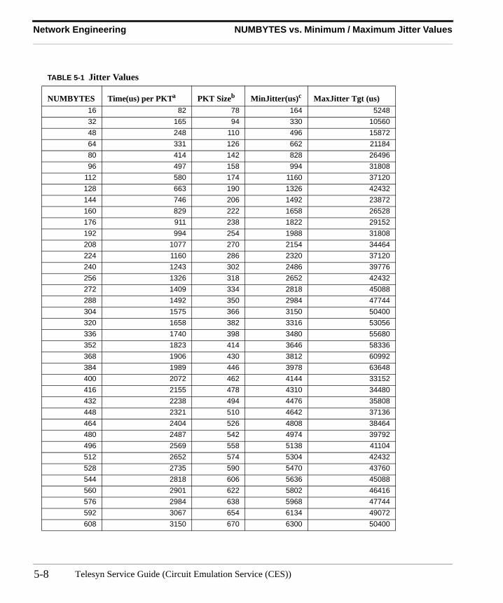
Network Engineering NUMBYTES vs. Minimum / Maximum Jitter Values
TABLE 5-1 Jitter Values
NUMBYTES Time(us) per PKTa PKT Sizeb MinJitter(us)c MaxJitter Tgt (us)16 82 78 164 524832 165 94 330 1056048 248 110 496 1587264 331 126 662 2118480 414 142 828 2649696 497 158 994 31808
112 580 174 1160 37120128 663 190 1326 42432144 746 206 1492 23872160 829 222 1658 26528176 911 238 1822 29152192 994 254 1988 31808208 1077 270 2154 34464224 1160 286 2320 37120240 1243 302 2486 39776256 1326 318 2652 42432272 1409 334 2818 45088288 1492 350 2984 47744304 1575 366 3150 50400320 1658 382 3316 53056336 1740 398 3480 55680352 1823 414 3646 58336368 1906 430 3812 60992384 1989 446 3978 63648400 2072 462 4144 33152416 2155 478 4310 34480432 2238 494 4476 35808448 2321 510 4642 37136464 2404 526 4808 38464480 2487 542 4974 39792496 2569 558 5138 41104512 2652 574 5304 42432528 2735 590 5470 43760544 2818 606 5636 45088560 2901 622 5802 46416576 2984 638 5968 47744592 3067 654 6134 49072608 3150 670 6300 50400
Telesyn Service Guide (Circuit Emulation Service (CES))5-8
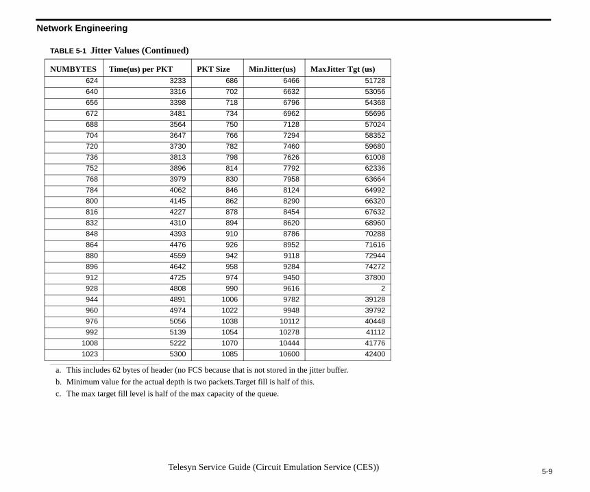
5-9
N
Telesyn Service Guide (Circuit Emulation Service (CES))
etwork Engineering
NUMBYTES Time(us) per PKT PKT Size MinJitter(us) MaxJitter Tgt (us)624 3233 686 6466 51728640 3316 702 6632 53056656 3398 718 6796 54368672 3481 734 6962 55696688 3564 750 7128 57024704 3647 766 7294 58352720 3730 782 7460 59680736 3813 798 7626 61008752 3896 814 7792 62336768 3979 830 7958 63664784 4062 846 8124 64992800 4145 862 8290 66320816 4227 878 8454 67632832 4310 894 8620 68960848 4393 910 8786 70288864 4476 926 8952 71616880 4559 942 9118 72944896 4642 958 9284 74272912 4725 974 9450 37800928 4808 990 9616 2944 4891 1006 9782 39128960 4974 1022 9948 39792976 5056 1038 10112 40448992 5139 1054 10278 41112
1008 5222 1070 10444 417761023 5300 1085 10600 42400
a. This includes 62 bytes of header (no FCS because that is not stored in the jitter buffer.b. Minimum value for the actual depth is two packets.Target fill is half of this.c. The max target fill level is half of the max capacity of the queue.
TABLE 5-1 Jitter Values (Continued)
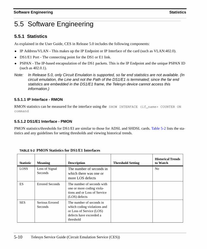
Software Engineering Statistics
5.5 Software Engineering
5.5.1 StatisticsAs explained in the User Guide, CES in Release 5.0 includes the following components:
• IP Address/VLAN - This makes up the IP Endpoint or IP Interface of the card (such as VLAN:402.0).• DS1/E1 Port - The connecting point for the DS1 or E1 link.• PSPAN - The IP-based encapsulation of the DS1 packets. This is the IP Endpoint and the unique PSPAN ID
(such as 402.0.1).
Note: In Release 5.0, only Circuit Emulation is supported, so far end statistics are not available. (In circuit emulation, the Line and not the Path of the DS1/E1 is terminated; since the far end statistics are embedded in the DS1/E1 frame, the Telesyn device cannot access this information.)
5.5.1.1 IP Interface - RMON
RMON statistics can be measured for the interface using the SHOW INTERFACE (if_name> COUNTER ON command
5.5.1.2 DS1/E1 Interface - PMON
PMON statistics/thresholds for DS1/EI are similar to those for ADSL and SHDSL cards. Table 5-2 lists the sta-tistics and any guidelines for setting thresholds and viewing historical trends.
TABLE 5-2 PMON Statistics for DS1/E1 Interfaces
Statistic Meaning Description Threshold SettingHistorical Trends to Watch
LOSS Loss of Signal Seconds
The number of seconds in which there was one or more LOS defects
No
ES Errored Seconds The number of seconds with one or more coding viola-tions and or Loss of Service (LOS) defects
SES Serious Errored Seconds
The number of seconds in which coding violations and or Loss of Service (LOS) defects have exceeded a threshold
Telesyn Service Guide (Circuit Emulation Service (CES))5-10
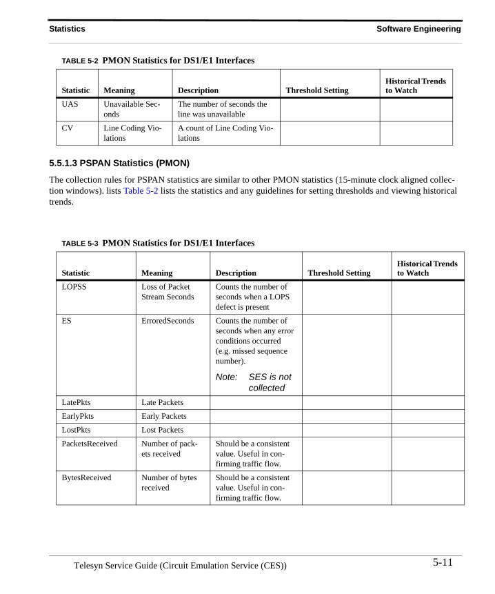
Statistics Software Engineering
5.5.1.3 PSPAN Statistics (PMON)
The collection rules for PSPAN statistics are similar to other PMON statistics (15-minute clock aligned collec-tion windows). lists Table 5-2 lists the statistics and any guidelines for setting thresholds and viewing historical trends.
UAS Unavailable Sec-onds
The number of seconds the line was unavailable
CV Line Coding Vio-lations
A count of Line Coding Vio-lations
TABLE 5-3 PMON Statistics for DS1/E1 Interfaces
Statistic Meaning Description Threshold SettingHistorical Trends to Watch
LOPSS Loss of Packet Stream Seconds
Counts the number of seconds when a LOPS defect is present
ES ErroredSeconds Counts the number of seconds when any error conditions occurred (e.g. missed sequence number).
Note: SES is not collected
LatePkts Late Packets
EarlyPkts Early Packets
LostPkts Lost Packets
PacketsReceived Number of pack-ets received
Should be a consistent value. Useful in con-firming traffic flow.
BytesReceived Number of bytes received
Should be a consistent value. Useful in con-firming traffic flow.
TABLE 5-2 PMON Statistics for DS1/E1 Interfaces
Statistic Meaning Description Threshold SettingHistorical Trends to Watch
5-11Telesyn Service Guide (Circuit Emulation Service (CES))
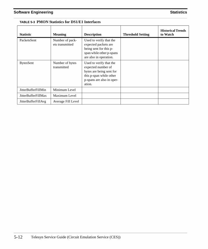
Software Engineering Statistics
PacketsSent Number of pack-ets transmitted
Used to verify that the expected packets are being sent for this p-span while other p-spans are also in operation.
BytesSent Number of bytes transmitted
Used to verify that the expected number of bytes are being sent for this p-span while other p-spans are also in oper-ation.
JitterBufferFillMin Minimum Level
JitterBufferFillMax Maximum Level
JitterBufferFillAvg Average Fill Level
TABLE 5-3 PMON Statistics for DS1/E1 Interfaces
Statistic Meaning Description Threshold SettingHistorical Trends to Watch
Telesyn Service Guide (Circuit Emulation Service (CES))5-12
6. Ethernet Passive Optical Network (EPON)
6.1 Overview Refer to the Telesyn User Guide for an overview of the Ethernet Passive Optical Network implementation using the EPON2 card and the iMG/RG that includes the ONU.
6.2 Traffic ManagementThis subsection highlights how traffic management is handled for the EPON configuration.
6.2.1 ClassifiersFiltering is based on VLAN and IPSOURCE address.
IPSOURCE filtering can be done:
• Statically, using ACL or user classifiers• Dynamically, using the Auto_IP filtering option on DHCP relay.
Note the following rules for classification; these are enforced by the CLI:
• The VID match rule is required on all IP filters.• Ingress metering is not supported.• The user can do only FORWARD and DROP actions (e.g. can't COUNT, remark, etc.).• There is no support for IP address masks .• All FORWARD actions precede any DROP actions, and all DROP actions follow any FORWARD actions.
Note: These attributes are included in the summary tables in Section 17.1.
6.2.2 QoS (Traffic Queues/Priorities)With the introduction of the Service Level Agreement (SLA) model, there is a change in how traffic is prioritized as it flows upstream and downstream. Between the OLT and ONU, traffic management is done as follows:
• The SLA provides traffic management per VLAN• The SLA must take into account all traffic on that VLAN (service, ping, DHCP, etc.)
6-1 Telesyn Service Guide (Ethernet Passive Optical Network (EPON))
Traffic Management Connection Admission Control (CAC)
At points outside the OLT-ONU, p-bits/classifiers may still used at various points; moreover, these are passed through the OLT-ONU. This has the following results:
• In the upstream direction, traffic is passed with no controls from the UNI to the ONU. From the OLT to the ONU, the SLA is used to prioritize traffic flows per VLAN as follows:• High - UPDELAYSENSITIVITY=Sensitive• Medium - UPDELAYSENSITIVITY=Tolerant, MINUPSTREAMRATE not=0• Low - MINUPSTREAMRATE=0
At the EPON interface, p-bits may be used with the VPRIORITY setting to separate and prioritize traffic for up to 8 queues.
Note: The user must be sure that there are no conflicts between the flows set up by the SLA and those by the p-bit settings, since they are separate traffic management tools.
• In the downstream direction, p-bits/classifiers are set at the EPON interface. For known unicast traffic (non-video and non-BRUUM), the SLA per VLAN is used to prioritize the data flows. At the ONU, the p-bit/clas-sifier settings are passed down to the ONU and are actually applied to the traffic flows.
Note: Traffic management is therefore not performed by the EPON but by the ONU, which has the interface to the UNI. The ONU is modeled as an Telesyn extension.
6.2.3 Connection Admission Control (CAC)The CAC function is to ensure the hardware can provide the guarantees configured by the SLAs. There are two type of CAC check on the EPON2 interface:
1. Sum of Minimum Bandwidths - The sum of provisioned minimum bandwidths for the QOSPOLICYs of all logical links on an EPON port must not exceed the bandwidth capacity of that port in either upstream or downstream direction. This limit is slightly below 1G due to administrative overhead (REPORTs, GRANTs, OAMPDUs, etc.). This function is performed in OAM so that CAC can be enforced even if the EPON2 card is not physically present (i.e. when pre-provisioning).
Telesyn Service Guide (Ethernet Passive Optical Network (EPON))6-2
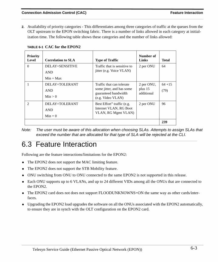
Connection Admission Control (CAC) Feature Interaction
2. Availability of priority categories - This differentiates among three categories of traffic at the queues from the OLT upstream to the EPON switching fabric. There is a number of links allowed in each category at initial-ization time. The following table shows these categories and the number of links allowed:
Note: The user must be aware of this allocation when choosing SLAs. Attempts to assign SLAs that exceed the number that are allocated for that type of SLA will be rejected at the CLI.
6.3 Feature InteractionFollowing are the feature interactions/limitations for the EPON2:
• The EPON2 does not support the MAC limiting feature.• The EPON2 does not support the STB Mobility feature.• ONU switching from ONU to ONU connected to the same EPON2 is not supported in this release.• Each ONU supports up to 6 VLANs, and up to 24 different VIDs among all the ONUs that are connected to
the EPON2.• The EPON2 card does not does not support FLOODUNKNOWNS=ON the same way as other cards/inter-
faces. • Upgrading the EPON2 load upgrades the software on all the ONUs associated with the EPON2 automatically,
to ensure they are in synch with the OLT configuration on the EPON2 card.
TABLE 6-1 CAC for the EPON2
Priority Level Correlation to SLA Type of Traffic
Number of Links Total
0 DELAY=SENSITIVE
AND
Min = Max
Traffic that is sensitive to jitter (e.g. Voice VLAN)
2 per ONU 64
1 DELAY=TOLERANT
AND
Min > 0
Traffic that can tolerate some jitter, and has some guaranteed bandwidth (e.g. Video VLAN)
2 per ONU, plus 15 additional
64 +15
(79)
2 DELAY=TOLERANT
AND
Min = 0
Best Effort” traffic (e.g. Internet VLAN, RG Boot VLAN, RG Mgmt VLAN)
2 per ONU 96
239
6-3Telesyn Service Guide (Ethernet Passive Optical Network (EPON))
Feature Interaction Connection Admission Control (CAC)
Telesyn Service Guide (Ethernet Passive Optical Network (EPON))6-4
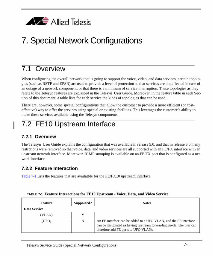
7. Special Network Configurations
7.1 Overview When configuring the overall network that is going to support the voice, video, and data services, certain topolo-gies (such as RSTP and EPSR) are used to provide a level of protection so that services are not affected in case of an outage of a network component, or that there is a minimum of service interruption. These topologies as they relate to the Telesyn features are explained in the Telesyn User Guide. Moreover, in the feature table in each Sec-tion of this document, a table lists for each service the kinds of topologies that can be used.
There are, however, some special configurations that allow the customer to provide a more efficient (or cost-effective) way to offer the services using special or existing facilities. This leverages the customer’s ability to make these services available using the Telesyn components.
7.2 FE10 Upstream Interface
7.2.1 OverviewThe Telesyn User Guide explains the configuration that was available in release 5.0, and that in release 6.0 many restrctions were removed so that voice, data, and video services are all supported with an FE/FX interface with an upstream network interface. Moreover, IGMP snooping is available on an FE/FX port that is configured as a net-work interface.
7.2.2 Feature InteractionTable 7-1 lists the features that are availalble for the FE/FX10 upstream interface.
TABLE 7-1 Feature Interactions for FE10 Upstream - Voice, Data, and Video Service
Feature Supported? Notes
Data Service
(VLAN) Y
(UFO) N An FE interface can be added to a UFO VLAN, and the FE interface can be designated as having upstream forwarding mode. The user can therefore add FE ports to UFO VLANs.
7-1 Telesyn Service Guide (Special Network Configurations)
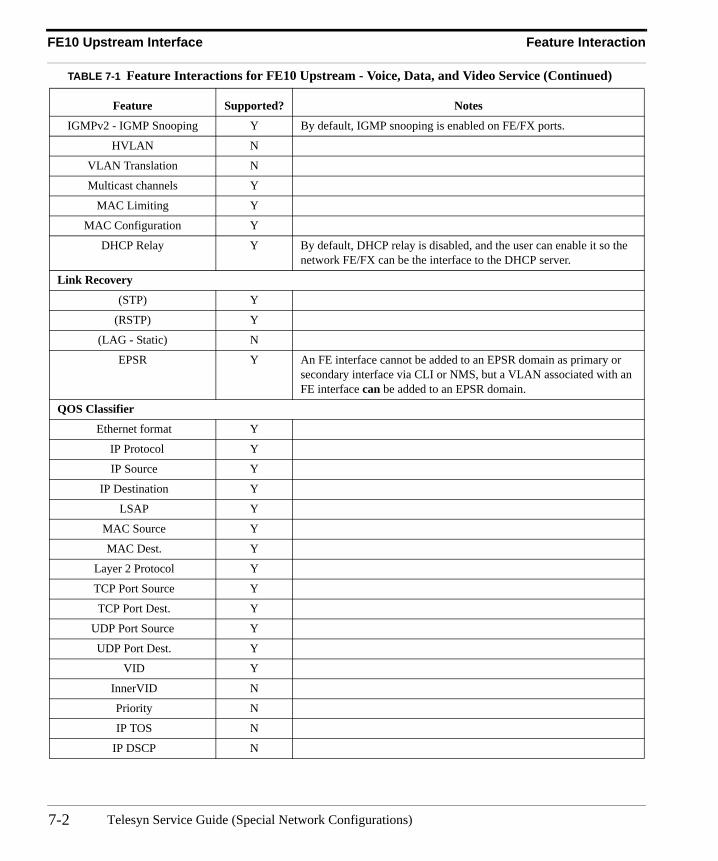
FE10 Upstream Interface Feature Interaction
IGMPv2 - IGMP Snooping Y By default, IGMP snooping is enabled on FE/FX ports.
HVLAN N
VLAN Translation N
Multicast channels Y
MAC Limiting Y
MAC Configuration Y
DHCP Relay Y By default, DHCP relay is disabled, and the user can enable it so the network FE/FX can be the interface to the DHCP server.
Link Recovery
(STP) Y
(RSTP) Y
(LAG - Static) N
EPSR Y An FE interface cannot be added to an EPSR domain as primary or secondary interface via CLI or NMS, but a VLAN associated with an FE interface can be added to an EPSR domain.
QOS Classifier
Ethernet format Y
IP Protocol Y
IP Source Y
IP Destination Y
LSAP Y
MAC Source Y
MAC Dest. Y
Layer 2 Protocol Y
TCP Port Source Y
TCP Port Dest. Y
UDP Port Source Y
UDP Port Dest. Y
VID Y
InnerVID N
Priority N
IP TOS N
IP DSCP N
TABLE 7-1 Feature Interactions for FE10 Upstream - Voice, Data, and Video Service (Continued)
Feature Supported? Notes
Telesyn Service Guide (Special Network Configurations)7-2
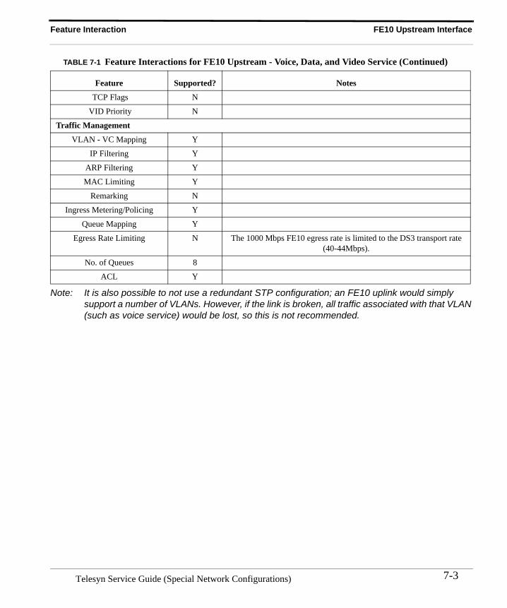
Feature Interaction FE10 Upstream Interface
Note: It is also possible to not use a redundant STP configuration; an FE10 uplink would simply support a number of VLANs. However, if the link is broken, all traffic associated with that VLAN (such as voice service) would be lost, so this is not recommended.
TCP Flags N
VID Priority N
Traffic Management
VLAN - VC Mapping Y
IP Filtering Y
ARP Filtering Y
MAC Limiting Y
Remarking N
Ingress Metering/Policing Y
Queue Mapping Y
Egress Rate Limiting N The 1000 Mbps FE10 egress rate is limited to the DS3 transport rate (40-44Mbps).
No. of Queues 8
ACL Y
TABLE 7-1 Feature Interactions for FE10 Upstream - Voice, Data, and Video Service (Continued)
Feature Supported? Notes
7-3Telesyn Service Guide (Special Network Configurations)
FE10 Upstream Interface Feature Interaction
Telesyn Service Guide (Special Network Configurations)7-4
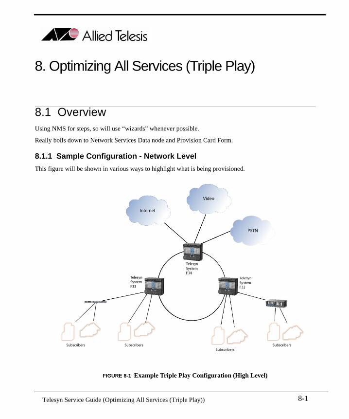
8. Optimizing All Services (Triple Play)
8.1 OverviewUsing NMS for steps, so will use “wizards” whenever possible.
Really boils down to Network Services Data node and Provision Card Form.
8.1.1 Sample Configuration - Network LevelThis figure will be shown in various ways to highlight what is being provisioned.
FIGURE 8-1 Example Triple Play Configuration (High Level)
Internet
Video
PSTN
TelesynSystemF33
Subscribers SubscribersSubscribers
Subscribers
8-1 Telesyn Service Guide (Optimizing All Services (Triple Play))
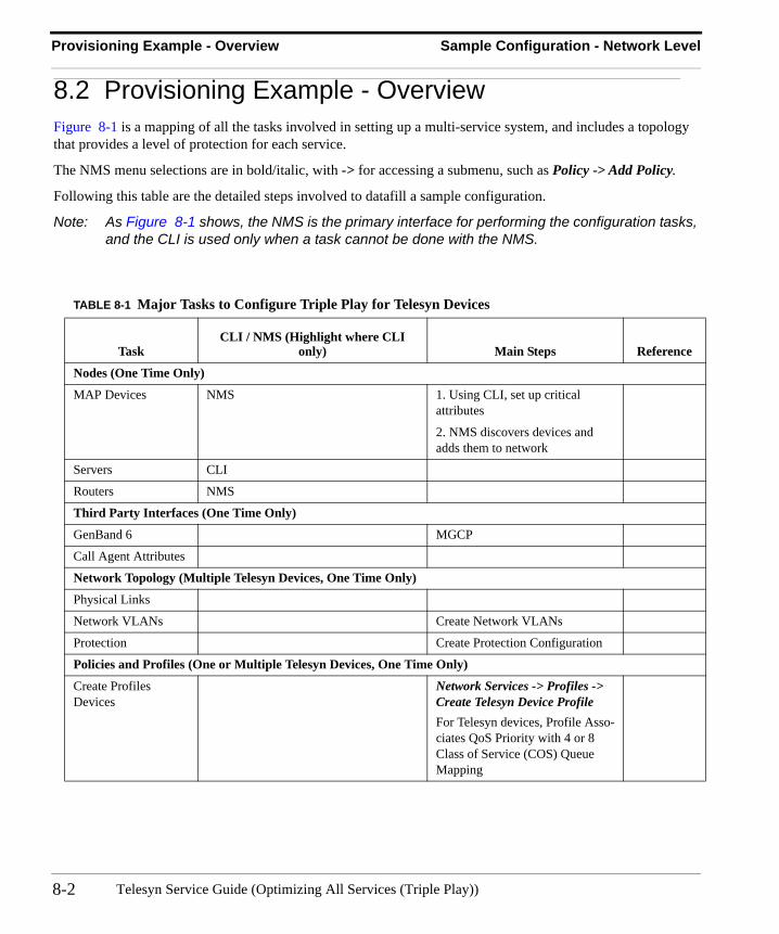
Provisioning Example - Overview Sample Configuration - Network Level
8.2 Provisioning Example - OverviewFigure 8-1 is a mapping of all the tasks involved in setting up a multi-service system, and includes a topology that provides a level of protection for each service.
The NMS menu selections are in bold/italic, with -> for accessing a submenu, such as Policy -> Add Policy.
Following this table are the detailed steps involved to datafill a sample configuration.
Note: As Figure 8-1 shows, the NMS is the primary interface for performing the configuration tasks, and the CLI is used only when a task cannot be done with the NMS.
TABLE 8-1 Major Tasks to Configure Triple Play for Telesyn Devices
TaskCLI / NMS (Highlight where CLI
only) Main Steps Reference
Nodes (One Time Only)
MAP Devices NMS 1. Using CLI, set up critical attributes
2. NMS discovers devices and adds them to network
Servers CLI
Routers NMS
Third Party Interfaces (One Time Only)
GenBand 6 MGCP
Call Agent Attributes
Network Topology (Multiple Telesyn Devices, One Time Only)
Physical Links
Network VLANs Create Network VLANs
Protection Create Protection Configuration
Policies and Profiles (One or Multiple Telesyn Devices, One Time Only)
Create Profiles Devices
Network Services -> Profiles -> Create Telesyn Device ProfileFor Telesyn devices, Profile Asso-ciates QoS Priority with 4 or 8 Class of Service (COS) Queue Mapping
Telesyn Service Guide (Optimizing All Services (Triple Play))8-2
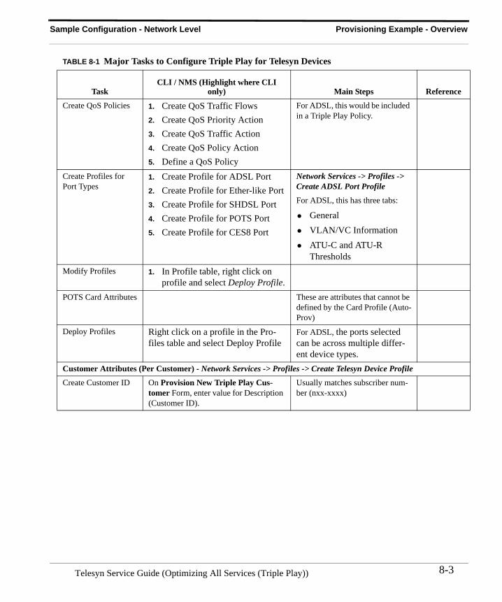
Sample Configuration - Network Level Provisioning Example - Overview
Create QoS Policies 1. Create QoS Traffic Flows2. Create QoS Priority Action3. Create QoS Traffic Action4. Create QoS Policy Action5. Define a QoS Policy
For ADSL, this would be included in a Triple Play Policy.
Create Profiles for Port Types
1. Create Profile for ADSL Port2. Create Profile for Ether-like Port3. Create Profile for SHDSL Port4. Create Profile for POTS Port5. Create Profile for CES8 Port
Network Services -> Profiles -> Create ADSL Port Profile
For ADSL, this has three tabs:
• General• VLAN/VC Information• ATU-C and ATU-R
ThresholdsModify Profiles 1. In Profile table, right click on
profile and select Deploy Profile.POTS Card Attributes These are attributes that cannot be
defined by the Card Profile (Auto-Prov)
Deploy Profiles Right click on a profile in the Pro-files table and select Deploy Profile
For ADSL, the ports selected can be across multiple differ-ent device types.
Customer Attributes (Per Customer) - Network Services -> Profiles -> Create Telesyn Device Profile
Create Customer ID On Provision New Triple Play Cus-tomer Form, enter value for Description (Customer ID).
Usually matches subscriber num-ber (nxx-xxxx)
TABLE 8-1 Major Tasks to Configure Triple Play for Telesyn Devices
TaskCLI / NMS (Highlight where CLI
only) Main Steps Reference
8-3Telesyn Service Guide (Optimizing All Services (Triple Play))
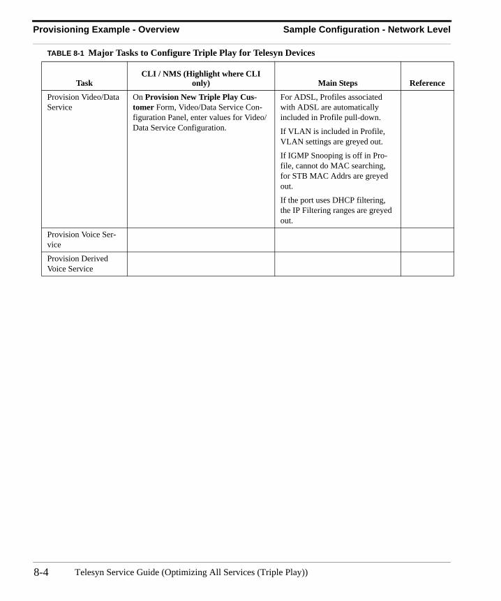
Provisioning Example - Overview Sample Configuration - Network Level
Provision Video/Data Service
On Provision New Triple Play Cus-tomer Form, Video/Data Service Con-figuration Panel, enter values for Video/Data Service Configuration.
For ADSL, Profiles associated with ADSL are automatically included in Profile pull-down.
If VLAN is included in Profile, VLAN settings are greyed out.
If IGMP Snooping is off in Pro-file, cannot do MAC searching, for STB MAC Addrs are greyed out.
If the port uses DHCP filtering, the IP Filtering ranges are greyed out.
Provision Voice Ser-vice
Provision Derived Voice Service
TABLE 8-1 Major Tasks to Configure Triple Play for Telesyn Devices
TaskCLI / NMS (Highlight where CLI
only) Main Steps Reference
Telesyn Service Guide (Optimizing All Services (Triple Play))8-4


![Allied Telesyn Government Allied Telesyn Centrecom Manual[1]](https://img.pdfslide.us/doc/110x75/547ef4015806b5d15e8b47a8/allied-telesyn-government-allied-telesyn-centrecom-manual1.jpg)