Embed Size (px)
Citation preview
TELESCOPIC JACKS
TELESCOPIC JACKS SELECTION
Here below the needed data for the selection of the right telescopic jack:
Q = rated car load [kg]P3 = empty car weight + car sling + accessories [kg]H = car travel [m]B = lower car overtravel [m]T = upper car overtravel [m]S = jack stroke [m]gn = acceleration of gravity [9,80665 m/s2]Pr = rams weight (see tab. OVERALL DIM. AND TECHNICAL DATA) [kg]Ar = small ram area (see tab. OVERALL DIM. AND TECHNICAL DATA) [mm2]
The data needed for jack selection can be obtained using the following formulas:
T = total load applied [daN]:
– direct acting:
• single jack: [1a]
• double jack: [1b]
Max static pressure (function of jack travel and max load T):
[MPa] [2]
Min static pressure:
[MPa] [3]
T Q P3+ gn
10------=
TQ P3+
2---------------------
gn
10------=
Pstmax Q P3 Pr+ + 7 06Ar
------------=
Pst P3 Pr+ 7 06Ar
------------=
HL 09.01 1/10Rev:ADate:01-04
Car speed calculation:v = car speed [m/s]:
• single jack: [4a]
• double jack: [4b]
with Ppump flow = pump flow [l/min.]
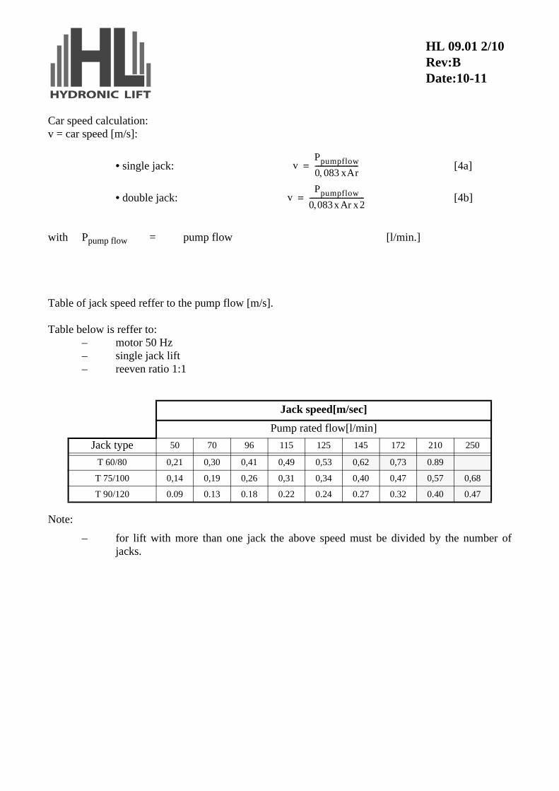
Table of jack speed reffer to the pump flow [m/s].
Table below is reffer to:– motor 50 Hz– single jack lift– reeven ratio 1:1
Note:
– for lift with more than one jack the above speed must be divided by the number ofjacks.
Jack speed[m/sec]
Pump rated flow[l/min]
Jack type 50 70 96 115 125 145 172 210 250
T 60/80 0,21 0,30 0,41 0,49 0,53 0,62 0,73 0.89
T 75/100 0,14 0,19 0,26 0,31 0,34 0,40 0,47 0,57 0,68
T 90/120 0.09 0.13 0.18 0.22 0.24 0.27 0.32 0.40 0.47
vPpumpflow
0 083 xAr-------------------------=
vPpumpflow
0 083xAr x2--------------------------------=
HL 09.01 2/10Rev:BDate:10-11
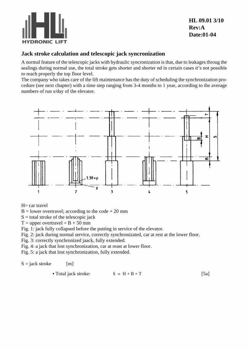
Jack stroke calculation and telescopic jack syncronization
A normal feature of the telescopic jacks with hydraulic syncronization is that, due to leakages throug thesealings during normal use, the total stroke gets shorter and shorter nd in certain cases it’s not possibleto reach properly the top floor level.The company who takes care of the lift maintenance has the duty of scheduling the synchronization pro-cedure (see next chapter) with a time step ranging from 3-4 months to 1 year, according to the averagenumbers of run s/day of the elevator.
H= car travelB = lower overtravel; according to the code + 20 mmS = total stroke of the telescopic jackT = upper overtravel = B + 50 mmFig. 1: jack fully collapsed before the putting in service of the elevator.Fig. 2: jack during normal service, correctly synchronizated, car at rest at the lower floor.Fig. 3: correctly synchronized jaack, fully extended.Fig. 4: a jack that lost synchronization, car at reast at lower floor.Fig. 5: a jack that lost synchronization, fully extended.
S = jack stroke [m]
• Total jack stroke: [5a]S H B T+ +=
HL 09.01 3/10Rev:ADate:01-04
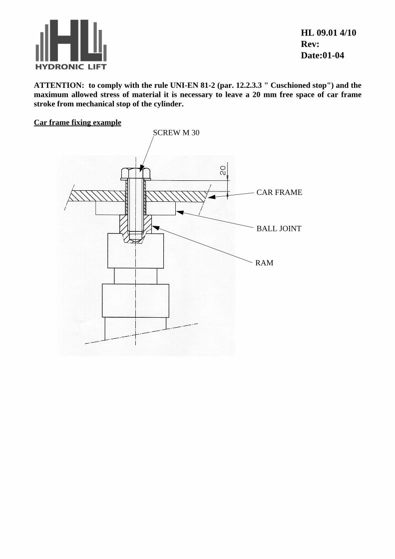
ATTENTION: to comply with the rule UNI-EN 81-2 (par. 12.2.3.3 " Cuschioned stop") and themaximum allowed stress of material it is necessary to leave a 20 mm free space of car framestroke from mechanical stop of the cylinder.
Car frame fixing exampleSCREW M 30
CAR FRAME
BALL JOINT
RAM
HL 09.01 4/10Rev:Date:01-04
JACK SELECTION USING GRAPHICS
The right jack can be selected using graphics reporting max admitted buckling load (safety factor = 2,8). Buckling calculations meet EN81/2 requirement.
If a selection based only on graphics is preferred, the process is the following:
– calculate the total load on the ram T (formulae 1a, 1b); trace on the graphic concerningthe selected jack a vertical line starting from T value.
– calculate buckling length (formulae 5a) and trace the horizontal line starting from Lvalue;
– find the intersection of the two lines and select the jack whose max load curve is justabove the intersection point;
– verify that min. static pressure and max. static pressure (formulae 2, 3) are in the admit-ted pressure range (max. 5,0 MPa, min 1,2 MPa).
HL 09.01 5/10Rev:ADate:01-04
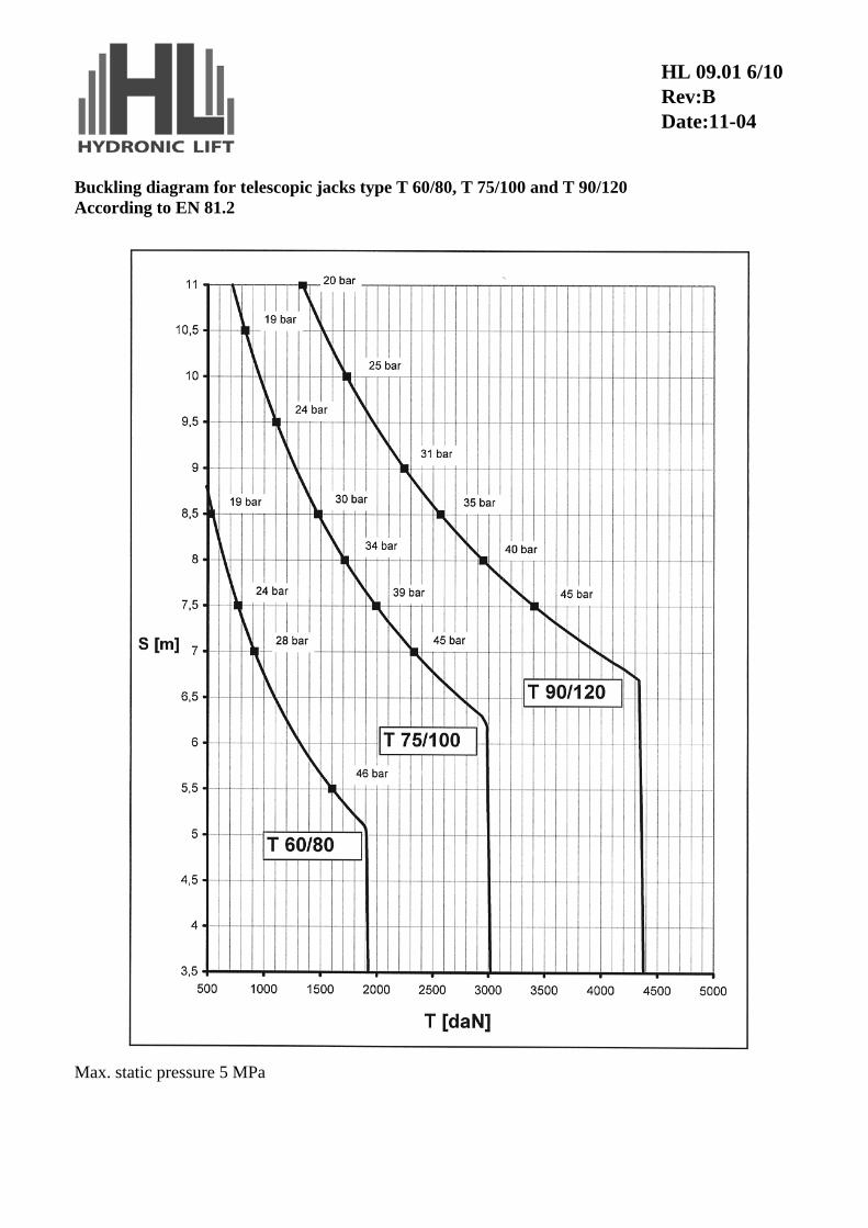
Buckling diagram for telescopic jacks type T 60/80, T 75/100 and T 90/120According to EN 81.2
Max. static pressure 5 MPa
HL 09.01 6/10Rev:BDate:11-04
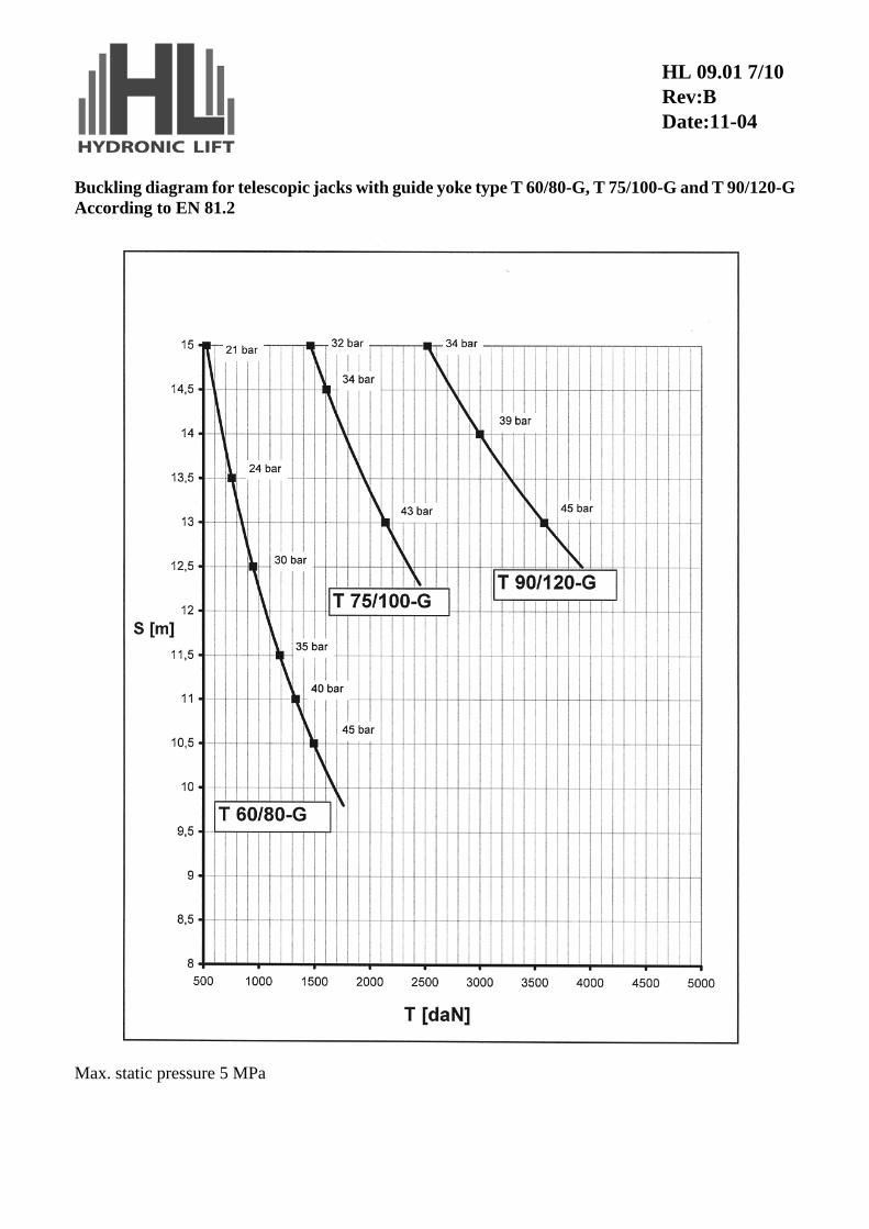
Buckling diagram for telescopic jacks with guide yoke type T 60/80-G, T 75/100-G and T 90/120-GAccording to EN 81.2
Max. static pressure 5 MPa
HL 09.01 7/10Rev:BDate:11-04
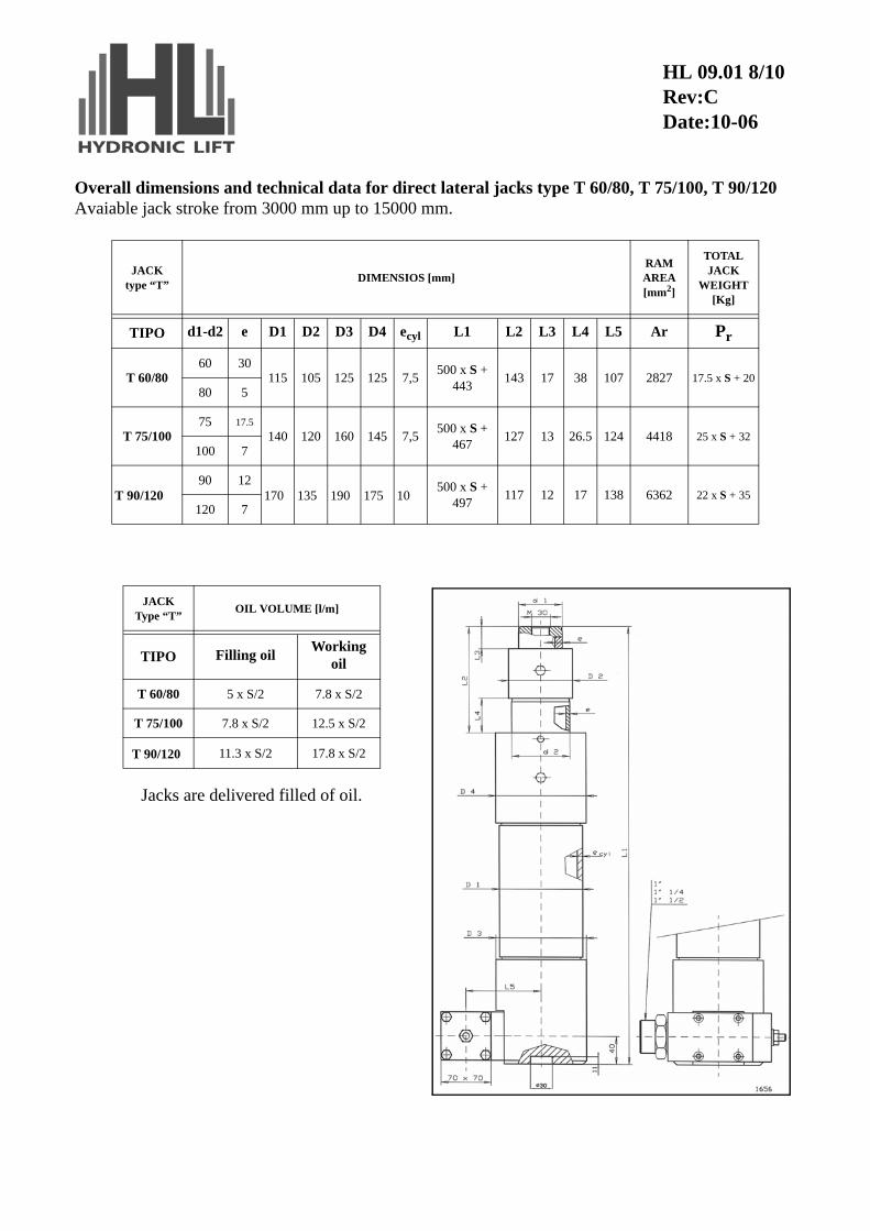
Overall dimensions and technical data for direct lateral jacks type T 60/80, T 75/100, T 90/120Avaiable jack stroke from 3000 mm up to 15000 mm.
JACKtype “T”
DIMENSIOS [mm]RAM AREA[mm2]
TOTAL JACK
WEIGHT [Kg]
TIPO d1-d2 e D1 D2 D3 D4 ecyl L1 L2 L3 L4 L5 Ar Pr
T 60/8060 30
115 105 125 125 7,5500 x S +
443143 17 38 107 2827 17.5 x S + 20
80 5
T 75/10075 17.5
140 120 160 145 7,5500 x S +
467127 13 26.5 124 4418 25 x S + 32
100 7
T 90/12090 12
170 135 190 175 10500 x S +
497117 12 17 138 6362 22 x S + 35
120 7
HL 09.01 8/10Rev:CDate:10-06
Jacks are delivered filled of oil.
JACKType “T”
OIL VOLUME [l/m]
TIPO Filling oilWorking
oil
T 60/80 5 x S/2 7.8 x S/2
T 75/100 7.8 x S/2 12.5 x S/2
T 90/120 11.3 x S/2 17.8 x S/2
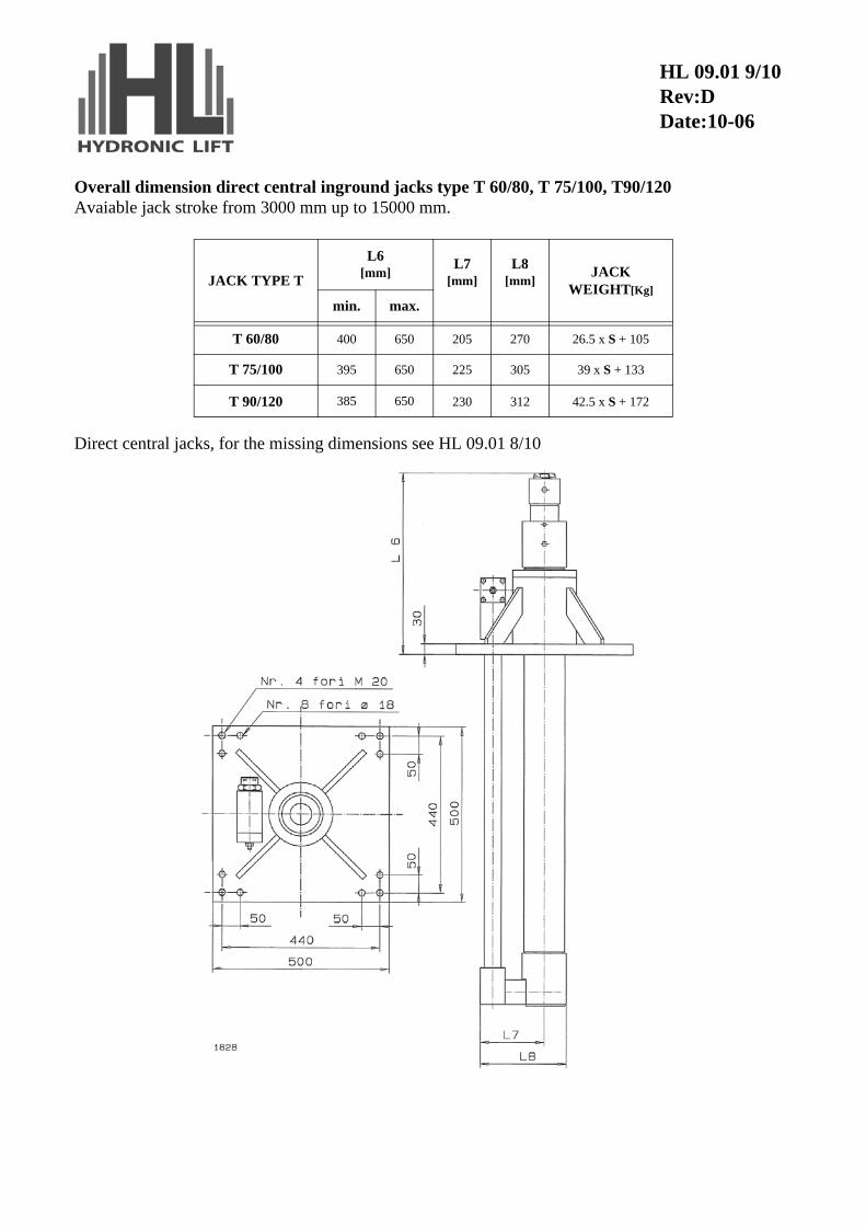
Overall dimension direct central inground jacks type T 60/80, T 75/100, T90/120Avaiable jack stroke from 3000 mm up to 15000 mm.
Direct central jacks, for the missing dimensions see HL 09.01 8/10
JACK TYPE T
L6 [mm]
L7 [mm]
L8 [mm]
JACK WEIGHT[Kg]
min. max.
T 60/80 400 650 205 270 26.5 x S + 105
T 75/100 395 650 225 305 39 x S + 133
T 90/120 385 650 230 312 42.5 x S + 172
HL 09.01 9/10Rev:DDate:10-06
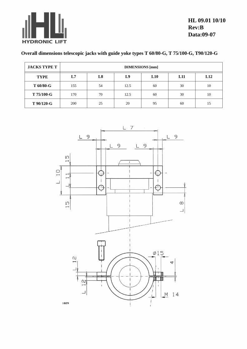
Overall dimensions telescopic jacks with guide yoke types T 60/80-G, T 75/100-G, T90/120-G
JACKS TYPE T DIMENSIONS [mm]
TYPE L7 L8 L9 L10 L11 L12
T 60/80-G 155 54 12.5 60 30 10
T 75/100-G 170 70 12.5 60 30 10
T 90/120-G 200 25 20 95 60 15
HL 09.01 10/10Rev:BData:09-07
BLEEDING, RE-SYNCHRONIZATION AND TEST BEFORE PUTTING INTOSERVICE PROCEDURE HYDRONIC TELESCOPIC JACK
General carachteristics of the product :
– Jacks are delivered filled of oil.
– In dimensioning the lift it is suggested to calculate jack extra-stroke so that upper extra-stroke is > of at least 5 cm than low extra-stroke
– Jacks are delivered with shim for intermediate element which MUST be removed afteroil inlet hose connection has been executed
– Inside the jacks there is a device that deschargs, throught a little copper pipe, theinduced pressure when the upper ram arrive to the maximum extention.
– On the two heads of the jacks the holes for the bleeding, the oil leakage and the pressuredescharge are three 120° oriented. Plug the holes that aren’t in use.
During first installation:
After the connection of oil inlet hose to the installed jack and with car frame connected .
– Remove cabin pit bottom spring.
– Remove completely air bleed screw M6 from both cylinder head sealings of the jack,taking care to cover with a cloth the thread so to avoid oil splash.
– Remove coil of the high speed pilot valve of power unit and remove external shim ofjack intermediate element.
– Make several short upward call ( 1-3 sec.) . Rams will slide out of the jack duringworking of motorpump and get down once the motorpump doesn't work anymore.
– When some oil is outgoing from air bleed screws M6, close them down . Probably out-going of oil will not take place from both sides together, but it can happen that it getsout first from one cylinder head and then from the other.
– Once the two air bleed screw have been closed, make an upward call. Rams will have tomove together. In case one ram delays the movement compared to the other, of thesame jack, there must be some few air in internal space of cilynder. Repeat bleed oper-ation moving the bleed screw correspondent to the delayed ram.
HL 09.02 1/3Rev:AData:01-04
During normal use of lift:
To bleed air in case of its presence inside cylinder:
– Rest the lift so that the cylinder is fully collapsed (remove pit bottom springs )
– Remove bleed air screw
– Act as for the first installation
Synchronizing of a ram (two procedures are available):
Procedure A : as per air bleed
Procedure B :
– Make a full upward call, at slow speed, up to the internal mechanical stop of the jack(the elevator will be in upper extra travel).
– Keep working the motorpump for the time needed for complete extention of jackstages
CAUTION:
– when rams get stopped this means that complete fullfilment of synchronism, DO NOTinsist with motorpump working but stop the lift immediately.
HL 09.02 2/3Rev:AData:01-04
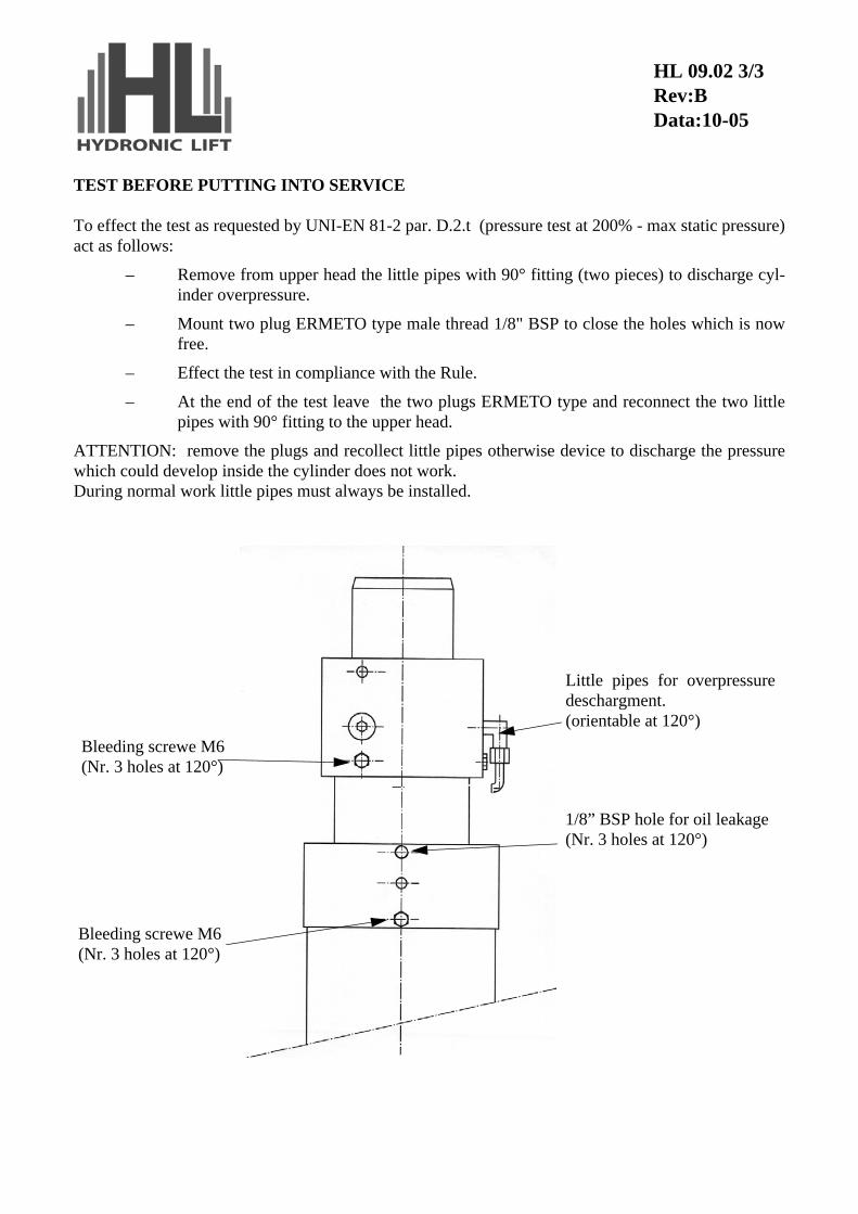
TEST BEFORE PUTTING INTO SERVICE
To effect the test as requested by UNI-EN 81-2 par. D.2.t (pressure test at 200% - max static pressure)act as follows:
– Remove from upper head the little pipes with 90° fitting (two pieces) to discharge cyl-inder overpressure.
– Mount two plug ERMETO type male thread 1/8" BSP to close the holes which is nowfree.
– Effect the test in compliance with the Rule.
– At the end of the test leave the two plugs ERMETO type and reconnect the two littlepipes with 90° fitting to the upper head.
ATTENTION: remove the plugs and recollect little pipes otherwise device to discharge the pressurewhich could develop inside the cylinder does not work.During normal work little pipes must always be installed.
Bleeding screwe M6(Nr. 3 holes at 120°)
Bleeding screwe M6(Nr. 3 holes at 120°)
1/8” BSP hole for oil leakage(Nr. 3 holes at 120°)
Little pipes for overpressuredeschargment.(orientable at 120°)
HL 09.02 3/3Rev:BData:10-05
SEALS SUBSTITUTION IN TELESCOPIC JACKSIntroduction
A correct distribution of cylinder extra-stroke allows to automathically recover little out of phase of theram due to unavoidable losses during shifting on seals. In case of considerable losses, visible on ram orwith out of phase of the ram which does not allow a regular work of the cylinder, it is necessary to con-sider a possible substitution of damaged seals.
We can have two different kind of problem depending on seals of telescopic jacks
First type, which is easily solvable, is the one due to losses visible from external side.External losses are usually the dinamic ones located in seals of ram due to early wear and tear or the static ones due to damages in seals.Other oil loss from inside to external side can occure due to defects or damages in air bleed caps or inO-Ring located inside the cylinder head, but they do not occur very often
Second type of losses is about internal sealing or non-return valve located at the bottom of the biggestram: to substitute this seal it is needed to completely unthread the ram. An early wear and tear of theseparts can be caused from impurity which are present in the oil.
We can test cylinder seals in static conditions, with partially unthread ram and shut off valve on powerunit off:
– If top ram tries to shift down, and the bottom ram tries to exit from the cylinder, we cansuppose a loss in internal seal or of non return valve.
– If both rams try to go into the cylinder and we have oil loss from cylinder head, wemust substitute external seals.
HL 09.03 1/4Rev:Data:09-03
Substitution of external seals
Change the seals only if there are more than 1.5 liter per mounth oil leakage
– Check if on ram you can see irregularities or roughnesses; in this case use some sandpaper directioning it in a transversal way on the irregular part putting some rags to pro-tect the cylinder head.
– Stop the cabin in the right position which allows you to better work on cylinder rampiston head. Untie the ram from the cabin and lower the rams till it reaches the cylinderbulkhead.
– Clean the ram piston head, the ram, and particularly remove defetcs from the ram pres-ently out of ram
– Unscrew the locking screw from the cylinder head
– Unscrew the cylinder head (giving a blow with a hammer to initially unthread it) andremove the cylinder head from the ram.
– Remove ram seal and scraper. Upper ram seal is closed site type therefore it remains onthe cylinder head; lower ram seal is open site type and it remains in the fix part of thecylinder.
– Check cleaning of ram guide rings.
– Assemble the new seal: do not use metallic or sharping objects to put it in its site. Payattention in assembling the seals in the correct way: on the seals there is the indicationPRESSURE SIDE for the right location
– Assemble the scraper in its site; before re-assembling the cylinder head be sure that thestatic O-Ring of the cylinder head not damaged. If it is damaged provide to substitute it.
– Check cleaning of cylider ram and ram threading and if needed, provide to grease them.
– Provide to slowly screw and finally tight with a resolute stroke
– Provide to screw the locking screw for the cylinder head.
– The jack is now ready to work, but before making it work an accurate air bleed musttake place not to compromise the synchronization of the cylinder.
HL 09.03 2/4Rev:Data:09-03
Subsitution of internal seal
N.B.:- change the seal only when you must sincronize the jack every 15 days- in case of replacement of the internal seal take note that:
– replacement of internal seal takes more time that replacemento of external seals (twomen for 8 hours)
– replacement must be performed by practise and trained people to avoid damage of therams, jack and contamination of oil
To make this operation possible, it is needed to have an equipment to be able to pull and keep the ramout of its cylinder, using, if needed, a clamp tied on lower ram which pulls on head cap. Moreover it isneeded to have a plastic bottle to collect the oil and a plastic tube suitable to be screwed in the air bleedhole of the cylinder.
– Stop the cabin in the right position which allows you to better work on cylinder plunger.ATTENTION: be sure to have enough space around the cylinder which allows you tocompletely unthread the lower ram.
– Provide to separate the upper ram from the car frames and lower the rams till cylinderbulkhead
– If power unit is located lower than the cylinder, provide to separate the pipe line disas-sembling the shut off valve from the control valve on the power unit and leave the oilflow to the tank. The pipe line has anyway to be disconnected to allow the air flowinside the cylidner during unthreading of it
– Connect the hose for oil leakage to one fo the bleed air hoses.
– Pull out slowly the ram checking the oil flow in the hose till the ram stops itself at theupper mechanical stop.
– Unscrew the locking screw of the upper cylinder head and unscrew the upper cylinderhead
– After having completely unscrewed the upper cylinder head, pull the ram till the inter-nal seal are completely out of the cylinder
– Substitute the seal: mounting the new sealing, pay attention first to insert the rubbercentral part and then the black lateral broken rings and the white ones. To substitute thenon return valve disassemble the "seeger" ring and the washer which locks it to the bot-tom of the lower ram and pull out the cartridge check valve using some "seeger" pliers.
– Re-insert the ram in the cylinder and leave it slowly down till it reaches the bottom ofhead cylinder locking it with its nut.
– The jack is now ready to work, but before making it work an accurate air bleed musttake place not to compromise the synchronization of the cylinder.
HL 09.03 3/4Rev:AData:01-04
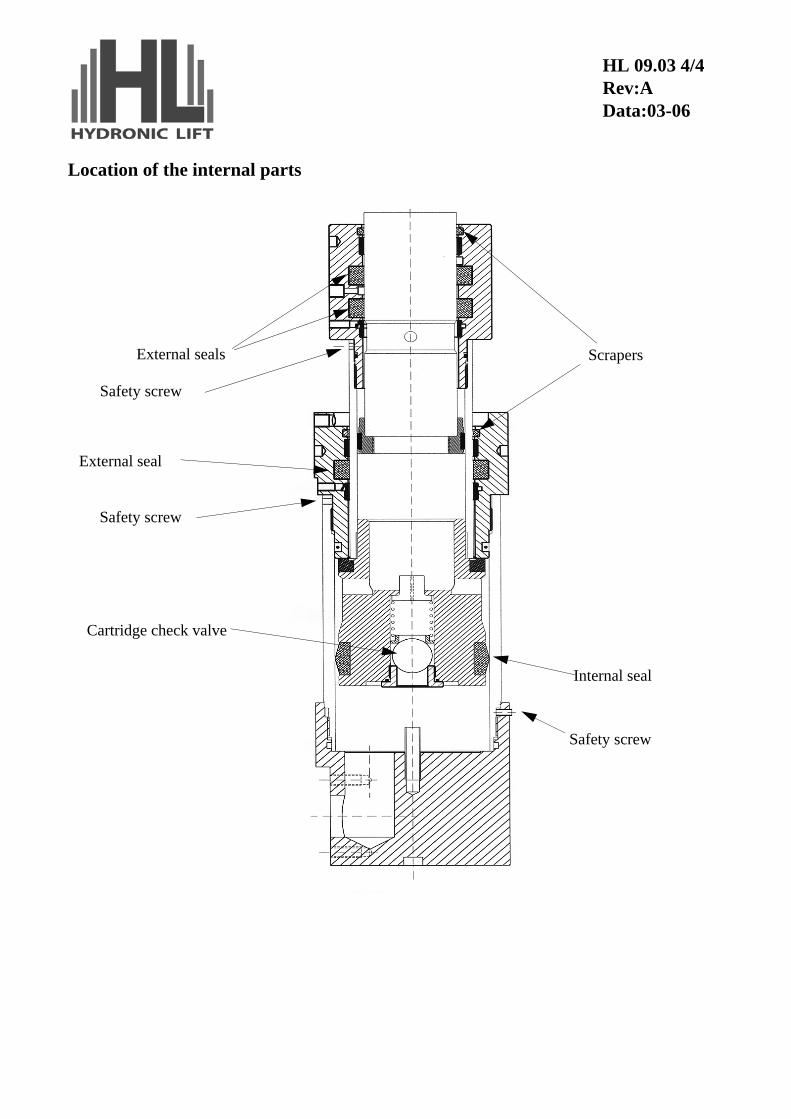
Location of the internal parts
External seals Scrapers
Internal seal
Cartridge check valve
External seal
Safety screw
Safety screw
Safety screw
HL 09.03 4/4Rev:AData:03-06


![PRESSURE TESTING [1] การตรวจสอบโดยใช้แรงดัน · pressure testing into 2 cases: 1. Hydrostatic Pressure Test. 2. Pneumatic Pressure Test](https://img.pdfslide.us/doc/110x75/5e6f0cdaf382de6744014cfb/pressure-testing-1-aaaaaaaaaaaaaafaaaaaaaa.jpg)