Embed Size (px)
Citation preview
4/07
1
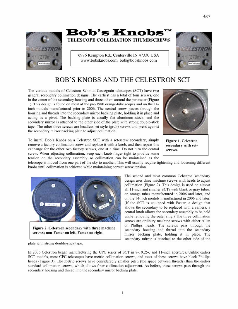
Figure 1. Celestron secondary with set-screws.
Figure 2. Celestron secondary with three machine screws; non-Faster on left, Fastar on right.
Bob’s Knobs™ TELESCOPE COLLIMATION THUMBSCREWS
6976 Kempton Rd., Centerville IN 47330 USA www.bobsknobs.com [email protected]
BOB’S KNOBS AND THE CELESTRON SCT
The various models of Celestron Schmidt-Cassegrain telescopes (SCT) have two general secondary collimation designs. The earliest has a total of four screws, one in the center of the secondary housing and three others around the perimeter (Figure 1). This design is found on most of the pre-1980 orange-tube scopes and on the 14-inch models manufactured prior to 2006. The central screw passes through the housing and threads into the secondary mirror backing plate, holding it in place and acting as a pivot. The backing plate is usually flat aluminum stock, and the secondary mirror is attached to the other side of the plate with strong double-stick tape. The other three screws are headless set-style (grub) screws and press against the secondary mirror backing plate to adjust collimation. To install Bob’s Knobs on a Celestron SCT with a set-screw secondary, simply remove a factory collimation screw and replace it with a knob, and then repeat this exchange for the other two factory screws, one at a time. Do not turn the central screw. When adjusting collimation, keep each knob finger tight to provide some tension on the secondary assembly so collimation can be maintained as the telescope is moved from one part of the sky to another. This will usually require tightening and loosening different knobs until collimation is achieved while maintaining correct screw tension.
The second and most common Celestron secondary design uses three machine screws with heads to adjust collimation (Figure 2). This design is used on almost all 11-inch and smaller SCTs with black or gray tubes, on orange tubes manufactured in 2006 and later, and on the 14-inch models manufactured in 2006 and later. (If the SCT is equipped with Fastar, a design that allows the secondary to be replaced with a camera, a central knob allows the secondary assembly to be held while removing the outer ring.) The three collimation screws are ordinary machine screws with either Allen or Phillips heads. The screws pass through the secondary housing and thread into the secondary mirror backing plate, holding it in place. The secondary mirror is attached to the other side of the
plate with strong double-stick tape. In 2006 Celestron began manufacturing the CPC series of SCT in 8-, 9.25-, and 11-inch apertures. Unlike earlier SCT models, most CPC telescopes have metric collimation screws, and most of these screws have black Phillips heads (Figure 3). The metric screws have considerably smaller pitch (the space between threads) than the earlier standard collimation screws, which allows finer collimation adjustment. As before, these screws pass through the secondary housing and thread into the secondary mirror backing plate.
4/07
2
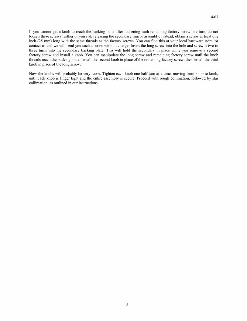
Figure 4. CPC 1100 secondary mirror backing plate (left) and inside of the secondary housing (right).
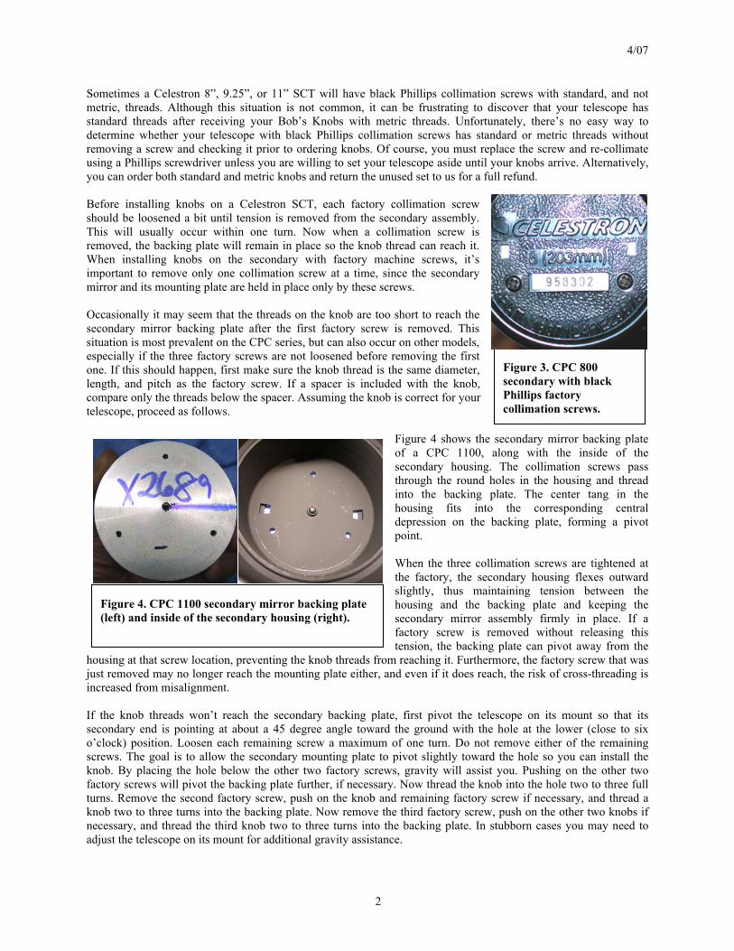
Figure 3. CPC 800 secondary with black Phillips factory collimation screws.
Sometimes a Celestron 8”, 9.25”, or 11” SCT will have black Phillips collimation screws with standard, and not metric, threads. Although this situation is not common, it can be frustrating to discover that your telescope has standard threads after receiving your Bob’s Knobs with metric threads. Unfortunately, there’s no easy way to determine whether your telescope with black Phillips collimation screws has standard or metric threads without removing a screw and checking it prior to ordering knobs. Of course, you must replace the screw and re-collimate using a Phillips screwdriver unless you are willing to set your telescope aside until your knobs arrive. Alternatively, you can order both standard and metric knobs and return the unused set to us for a full refund. Before installing knobs on a Celestron SCT, each factory collimation screw should be loosened a bit until tension is removed from the secondary assembly. This will usually occur within one turn. Now when a collimation screw is removed, the backing plate will remain in place so the knob thread can reach it. When installing knobs on the secondary with factory machine screws, it’s important to remove only one collimation screw at a time, since the secondary mirror and its mounting plate are held in place only by these screws. Occasionally it may seem that the threads on the knob are too short to reach the secondary mirror backing plate after the first factory screw is removed. This situation is most prevalent on the CPC series, but can also occur on other models, especially if the three factory screws are not loosened before removing the first one. If this should happen, first make sure the knob thread is the same diameter, length, and pitch as the factory screw. If a spacer is included with the knob, compare only the threads below the spacer. Assuming the knob is correct for your telescope, proceed as follows.
Figure 4 shows the secondary mirror backing plate of a CPC 1100, along with the inside of the secondary housing. The collimation screws pass through the round holes in the housing and thread into the backing plate. The center tang in the housing fits into the corresponding central depression on the backing plate, forming a pivot point. When the three collimation screws are tightened at the factory, the secondary housing flexes outward slightly, thus maintaining tension between the housing and the backing plate and keeping the secondary mirror assembly firmly in place. If a factory screw is removed without releasing this tension, the backing plate can pivot away from the
housing at that screw location, preventing the knob threads from reaching it. Furthermore, the factory screw that was just removed may no longer reach the mounting plate either, and even if it does reach, the risk of cross-threading is increased from misalignment. If the knob threads won’t reach the secondary backing plate, first pivot the telescope on its mount so that its secondary end is pointing at about a 45 degree angle toward the ground with the hole at the lower (close to six o’clock) position. Loosen each remaining screw a maximum of one turn. Do not remove either of the remaining screws. The goal is to allow the secondary mounting plate to pivot slightly toward the hole so you can install the knob. By placing the hole below the other two factory screws, gravity will assist you. Pushing on the other two factory screws will pivot the backing plate further, if necessary. Now thread the knob into the hole two to three full turns. Remove the second factory screw, push on the knob and remaining factory screw if necessary, and thread a knob two to three turns into the backing plate. Now remove the third factory screw, push on the other two knobs if necessary, and thread the third knob two to three turns into the backing plate. In stubborn cases you may need to adjust the telescope on its mount for additional gravity assistance.
4/07
3
If you cannot get a knob to reach the backing plate after loosening each remaining factory screw one turn, do not loosen these screws further or you risk releasing the secondary mirror assembly. Instead, obtain a screw at least one inch (25 mm) long with the same threads as the factory screws. You can find this at your local hardware store, or contact us and we will send you such a screw without charge. Insert the long screw into the hole and screw it two to three turns into the secondary backing plate. This will hold the secondary in place while you remove a second factory screw and install a knob. You can manipulate the long screw and remaining factory screw until the knob threads reach the backing plate. Install the second knob in place of the remaining factory screw, then install the third knob in place of the long screw. Now the knobs will probably be very loose. Tighten each knob one-half turn at a time, moving from knob to knob, until each knob is finger tight and the entire assembly is secure. Proceed with rough collimation, followed by star collimation, as outlined in our instructions.