Embed Size (px)
Citation preview

University of Wollongong University of Wollongong
Research Online Research Online
Coal Operators' Conference Faculty of Engineering and Information Sciences
2-2017
Telerescuer - reconnaissance mobile robot for underground coal mines Telerescuer - reconnaissance mobile robot for underground coal mines
Petr Novak University of Ostrava, [email protected]
Jan Babjak Technical University of Ostravia
Tomas Kot Technical University of Ostrava
Zdenko Bobovský Technical University of Ostrava
Petr Olivka Technical University of Ostrava
See next page for additional authors
Follow this and additional works at: https://ro.uow.edu.au/coal
Recommended Citation Recommended Citation Petr Novak, Jan Babjak, Tomas Kot, Zdenko Bobovský, Petr Olivka, Wojciech Moczulski, Anna Timofiejczuk, Marek Adamczyk, Borja Genoves Guzman, Ana Gaecia Armada, and Angel Rodriguez, Telerescuer - reconnaissance mobile robot for underground coal mines, in Naj Aziz and Bob Kininmonth (eds.), Proceedings of the 2017 Coal Operators' Conference, Mining Engineering, University of Wollongong, 18-20 February 2019 https://ro.uow.edu.au/coal/672
Research Online is the open access institutional repository for the University of Wollongong. For further information contact the UOW Library: [email protected]
Authors Authors Petr Novak, Jan Babjak, Tomas Kot, Zdenko Bobovský, Petr Olivka, Wojciech Moczulski, Anna Timofiejczuk, Marek Adamczyk, Borja Genoves Guzman, Ana Gaecia Armada, and Angel Rodriguez
This conference paper is available at Research Online: https://ro.uow.edu.au/coal/672
Coal Operators Conference The University of Wollongong
8-10 February 2017 332
TELERESCUER - RECONNAISSANCE MOBILE
ROBOT FOR UNDERGROUND COAL MINES
Petr Novák1, Jan Babjak1, Tomas Kot1, Zdenko Bobovský1, Petr Olivka1 Wojciech Moczulski2,3, Anna Timofiejczuk2, Marek Adamczyk2,3
Borja Genovés Guzmán4, Ana Garcia Armada4, Ángel Rodriguez4
ABSTRACT: The paper describes conception of a reconnaissance mobile robot TELERESCUER for
inspecting underground coal mine areas affected by catastrophic events. The introduction describes
the whole project background and the following sections deal with the design of the control system
and communication between individual subsystems. The subsystems described include the motion
subsystem, the sensory subsystem (temperatures, gas concentration, air flow, navigation and
cameras), the subsystem for 3D map data acquisition and the communication subsystem. Mentioned
also is the ATEX implementation (where the robot can safely operate in an environment with
dangerous concentrations of methane).
INTRODUCTION
The goal of the project “System of the mobile robot TELERESCUER for inspecting coal mine areas
affected by catastrophic events” is to develop a system for virtual teleportation (virtual immersion) of
rescuers to the subterranean areas of a coal mine that have been closed due to a catastrophic event
within them (Telerescuer, 2016; Timofiejczuk, et al. 2016; Moczulski, et al 2016.). Nowadays, human
rescuers inspect such areas alone. The activities of rescuers in places impacted by such disasters are
extremely dangerous. Moreover, human rescuers are allowed to enter a restricted area only if the
values of several critical parameters achieve acceptable levels, which often require long waiting
times. To overcome these problems and improve the efficiency of operation of the human rescuers, a
TeleRescuer system has been developed. The TeleRescuer system takes advantage of a special
Unmanned Vehicle (UV) capable of moving within the area affected by the catastrophic event (i.e.,
with many obstacles, such as parts of damaged machinery and equipment, fallen rocks, damaged
installations). The UV is equipped with sensors and video cameras. The requirements mentioned
above have to be guaranteed in surroundings where methane is present. It means that all robot
subsystems have to be designed in accordance with the ATEX requirement Group I, Category M1 –
“Equipment in this category is required to remain functional with an explosive atmosphere present”.
STATE OF ART
There are a number of projects relating to problems of mobile robots at underground coal mines. All
the projects mentioned below have one main problem in common – implementation of the ATEX in
the robot design. This is probably the most important difference for these robots when compared to
the “normal” field mobile robots. One of the projects, a Chinese mobile robot, shown in Figure 1 (Gao
Junyao, et al, 2009) – is a robot with six tracks, which weighs is 65 kg, travels at 3.2 km/h maximum
speed, has about 4 hours of working time (about 2 hours if moving continuously), can climb a slope of
30 degrees and can communication over a distance of 1 km. Additionally, it can carry 5 kg of food or
medical supplies. The robot shown in Figure 1 consists of a mechanical vehicle, driving system,
control system, communication system, sensor system, storage batteries and remote control system.
1 VŠB – Technical University of Ostrava, Faculty of Mechanical Engineering, Department of Robotics, Czech republic,
[email protected] Mob: +420 59 732 3595 2 SkyTech Research llc., Gliwice, Poland
3 Silesian University of Technology (SUT), Gliwice, Poland
4 Universidad Carlos III de Madrid, Spain

Coal Operators Conference The University of Wollongong
8-10 February 2017 333
Figure 1: Chinese coal mine rescue robot
Another example of a mobile robot designed for usage in coal mines is the Mine Rescue Robot
(MINBOT) described by (Wang, et al, 2014). Its second generation – MINBOT-II – is developed based
on the experiences learnt from the applications and experiments of the first generation (MINBOT-I)
shown in Figure 2.
Figure 2: Minibot-I robotic platform
The mobile robot NUMBAT shown in Figure 3 is a mine reconnaissance robot designed in the 1990s
by the Australian Commonwealth Scientific and Industrial Research Organization. The Numbat is an
eight-wheeled mobile platform with an on-board gas analysis package to provide information on the
environmental conditions within the mine (Jonathon, et al, 1998).
Figure 3: Robot Numbat
The mobile robots for coal mines described above have some disadvantages like their large size,
teleoperation only (no autonomy), no ability to create a 3D map of the surroundings and most
probably, problems with meeting the actual ATEX requirements. Other serious problems include:
communication distance is shorter than required, ability to overcome obstacles is low, autonomous
movement ability is weak or non-existent. Some tracked robots are not suitable for crossing rough
surfaces caused by an explosion in a coal mine. Thus the practical robot for detection and rescue in

Coal Operators Conference The University of Wollongong
8-10 February 2017 334
coal mine should have the abilities of movement on rough surface with obstacles, in smoke-filled and
dusty environments, must have the explosion-proof design (Chinese standards for these conditions
are less stringent when compared to European standards) and a waterproof design, many sensors,
wireless and safe communication (optimally with a backup line), a teleoperation system and other
subsystems like a 2D or 3D laser scanner for map building, autonomous behaviour, etc. Other
information about similar projects are mentioned e.g. in Kasprzyczak, et al, 2012; Kasprzyczak, et al,
2016.
SPECIFIC PROJECT OBJECTIVES
The identification of needs has been carried out in close collaboration with the Central Mining Rescue
Station (CMRS) (Timofiejczuk, et al, 2015). First, the rescuers filled out special questionnaires.
Additionally, interviews with experienced rescuers and discussions with the higher engineering
personnel of CMRS have been performed. Results of those activities have been summarized and
reported (Moczulski, et al 2014).
The platform should have the ability to pass obstacles such as conveyor structures, conveyor drives,
excavation protection structures and their intersections, hydraulic or wood racks, railroad tracks,
turnouts, loading ramps, winches, transformers, switchgear or single switches, pumps, hoses,
drainage, metal sheets, elements of concrete, construction machines and their fixing – beam, struts,
chains, wire ropes, tubes, pipes, cables, ventilation fans and chutes. In mine roadways there can be
present bulky materials (over 25 cm) left (abandoned) during transport, such as mining carts,
platform, locomotives, mine roof sections, components, parts, roadway support arches, concrete
lining, mesh lining, bales of ventilation cloth, metal and wooden racks, structural wood in the form of
timbers, planks, beams, metal crates and boxes used for transporting spare parts.
It is required to carry out measurements, transmission, visualization and recording of temperature and
humidity and temperature of selected elements of the robot body in a continuous way. Exceeding the
temperature threshold shall be indicated. The operator should be able to easily and quickly program
the contents of the measurement cycle. Registration of the results should include time stamps.
Placement of some sensors (CH4, O2) on a vertically retractable telescopic mast (independent of the
arm) – enables rising sensors up to 3 m. The required measurements of environmental parameters
and composition of mine atmosphere are:
Methane (CH4). Place of measurement: under the roof. Range: 0 to 5 % and 5 to 100 % vol.
Carbon monoxide (CO). Place of measurement: at face level. Range: 0 to 10000 ppm.
Carbon dioxide (CO2). Place of measurement: near the floor. Range: 0 to 5 % vol.
Oxygen (O2). Place of measurement: usually at face level. Range: 0 to 25 % vol.
Air flow (velocity and amount of air flow). Place of measurement: various methods but usually
at the whole cross section of the excavation. Measurement range: 0.2 to 20 m/s.
Temperature and relative humidity. Place of measurement: usually at face level in place of
free flow of air. Temperature range: -20 to +60°C. Relative humidity range: 0 to 100 % RH.
ACTUAL STAGE OF DEVELOPMENT
The TeleRescuer robot shown in Figure 4 consists of the main body with tracked arms (motors, motor
controllers, batteries and control system are encapsulated in a flameproof housing), a sensor arm with
a camera head (three degrees of freedom), a 3D laser scanner unit and a mote deploying subsystem
(motes are small Wi-Fi repeater modules with their own independent power units).
The most important part of the mobile robot is the sensor head on the sensor arm. The sensor head is
a cylindrical module with a flameproof enclosure. It is energy independent with its own batteries.
Communication with this module is done only through optical fibres (Ethernet). The sensor head
Coal Operators Conference The University of Wollongong
8-10 February 2017 335
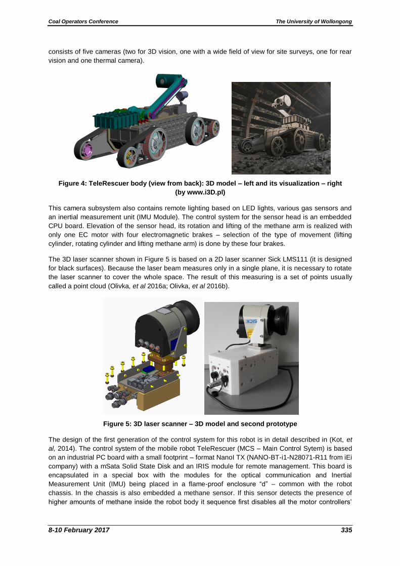
consists of five cameras (two for 3D vision, one with a wide field of view for site surveys, one for rear
vision and one thermal camera).
Figure 4: TeleRescuer body (view from back): 3D model – left and its visualization – right
(by www.i3D.pl)
This camera subsystem also contains remote lighting based on LED lights, various gas sensors and
an inertial measurement unit (IMU Module). The control system for the sensor head is an embedded
CPU board. Elevation of the sensor head, its rotation and lifting of the methane arm is realized with
only one EC motor with four electromagnetic brakes – selection of the type of movement (lifting
cylinder, rotating cylinder and lifting methane arm) is done by these four brakes.
The 3D laser scanner shown in Figure 5 is based on a 2D laser scanner Sick LMS111 (it is designed
for black surfaces). Because the laser beam measures only in a single plane, it is necessary to rotate
the laser scanner to cover the whole space. The result of this measuring is a set of points usually
called a point cloud (Olivka, et al 2016a; Olivka, et al 2016b).
Figure 5: 3D laser scanner – 3D model and second prototype
The design of the first generation of the control system for this robot is in detail described in (Kot, et
al, 2014). The control system of the mobile robot TeleRescuer (MCS – Main Control Sytem) is based
on an industrial PC board with a small footprint – format NanoI TX (NANO-BT-i1-N28071-R11 from iEi
company) with a mSata Solid State Disk and an IRIS module for remote management. This board is
encapsulated in a special box with the modules for the optical communication and Inertial
Measurement Unit (IMU) being placed in a flame-proof enclosure “d” – common with the robot
chassis. In the chassis is also embedded a methane sensor. If this sensor detects the presence of
higher amounts of methane inside the robot body it sequence first disables all the motor controllers’

Coal Operators Conference The University of Wollongong
8-10 February 2017 336
functionality (thus minimizing current consumption) and subsequently disconnects the power
subsystem. This way, the double explosion-proof safety required for Group I - M1 category is met.
Eight EC motors (4 for the track motion of each tracked arm and 4 for the rotation of these arms)
provide movement of the mobile robot. These motors are driven by four dual-channels RoboteQ
motor controllers connected to the MCS by the CAN bus. Each driver has an independent battery
pack with common grounding.
There are two independent subsystems for communication with the operation station. The first is
optical communication by optical fibre (solution n by Sedi-Ati Company). The secondary (backup)
communication channel is via wireless communication with a lower speed than through the optical
fibre, with a pack of releasable wireless repeater stations (motes). The subsystem are shown in
Figure 6.
Figure 6: Robot subsystems and their connections
MIGRATING TO ROS
The main change in the TeleRescuer control system is in the field of the operation system. The
original draft (Novák, et al 2014) was based on Microsoft Windows for both components (robot and
operator controller) but new requirements for the control system (especially the need for programming
of autonomous behaviour) forced to the migration to Robotic Operation System (ROS).
ROS is an open-source, meta-operating system for robotics systems. It provides the services
expected from an operating system, including hardware abstraction, low-level device control,
implementation of commonly-used functionality, message-passing between processes, and package
management. It also provides tools and libraries for obtaining, building, writing, and running code
across multiple computers. (In reality ROS is not a real operating system, but an extension of Linux.
ROS represents a verified framework for robot design with a wide range of supported devices and
libraries with many implemented algorithms. It is worth mentioning that Octomaps are an inseparable
Coal Operators Conference The University of Wollongong
8-10 February 2017 337
part of ROS. The usage of Octomaps and ROS is currently presented in many projects and robotic
competitions.)
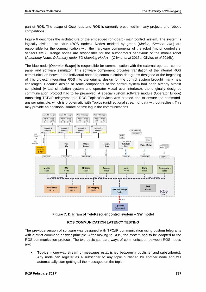
Figure 6 describes the architecture of the embedded (on-board) main control system. The system is
logically divided into parts (ROS nodes). Nodes marked by green (Motion, Sensors etc.) are
responsible for the communication with the hardware components of the robot (motor controllers,
sensors etc.). Orange nodes are responsible for the autonomous behaviour of the mobile robot
(Autonomy Node, Odometry node, 3D Mapping Node) – (Olivka, et al 2016a; Olivka, et al 2016b).
The blue node (Operator Bridge) is responsible for communication with the external operator control
panel and software simulator. This software component provides translation of the internal ROS
communication between the individual nodes to communication datagrams designed at the beginning
of this project. Integrating ROS into the original design for the control system brought many new
challenges. Because design of some components of the control system had been already almost
completed (virtual simulation system and operator visual user interface), the originally designed
communication protocol had to be preserved. A special custom software module (Operator Bridge)
translating TCP/IP telegrams into ROS Topics/Services was created and to ensure the command-
answer principle, which is problematic with Topics (unidirectional stream of data without replies). This
may provide an additional source of time lag in the communications.
Figure 7: Diagram of TeleRescuer control system – SW model
ROS COMMUNICATION LATENCY TESTING
The previous version of software was designed with TPC/IP communication using custom telegrams
with a strict command-answer principle. After moving to ROS, the system had to be adapted to the
ROS communication protocol. The two basic standard ways of communication between ROS nodes
are:
Topics – one-way stream of messages established between a publisher and subscriber(s).
Any node can register as a subscriber to any topic published by another node and will
automatically start getting all the messages on the topic.
Temp.
RoboteQ 1(Motion)
Motor +IRC
(Arm)
Motor+IRC
(Track)
Arm Tilt Sensor
AI
RoboteQ 2(Motion)
Motor+IRC
(Arm)
Motor+IRC
(Track)
Arm Tilt Sensor
RoboteQ 3(Motion)
Motor+IRC
(Arm)
Motor+IRC
(Track)
Arm Tilt Sensor
RoboteQ 4(Motion)
Motor+IRC
(Arm)
Motor+IRC
(Track)
Arm Tilt Sensor
Autonomy lock
Centralstop
AI AI AI
PwrCtrl PwrCtrl PwrCtrl PwrCtrlWDT WDT WDT WDT
Motion Node
IMU Node
USB/RS232
Main IMU
3D LaserNode
USB/RS232
3D Laser Scanner
Op
t. f
ibre
SensorsNode
Sensors,Lights
Eth
ern
et
ArmNode
USB/CAN
RoboteQ 5(Arm)
Op
t. f
ibre
Motes Effector
Autonomy Node
3D Mapping Node
Odometry Node
Operator (Windows)
Topics, Services
ROS
Topics, Services
(Linux)
ROSMasterOperator Bridge
Node
TCP/IP
Motes
MoteNode
USB/RS232USB/CAN
Op
t. f
ibre
TemperatureNode
USB/1wire
Temp.Temp.Temp.Temp.Temp.Temp.Temp.
Topics, Services
WDT
DO
Motor+IRC
DO
Tilt Sensor 1
AI
Tilt Sensor 2
AI
Enable
1w
ire
ARM cpu interface& WDT
Enab
le
Coal Operators Conference The University of Wollongong
8-10 February 2017 338
Services – pairs of messages (request and reply) exchanged between two nodes. A client
node calls a service provided by a server node by sending the request message, the server
node processes the request and answers with a reply.
The command-answer principle would suggest the usage of ROS Services. However, cleaner from
the ROS point of view would be to use of Topics for periodic commands or data feedback. For better
understanding of the internal implementation of Topics and Services, a series of performance tests
was performed. The goal was to to optimize data the exchange between the subsystems
(implemented as nodes) of the control system in order to get as low a latency as possible.
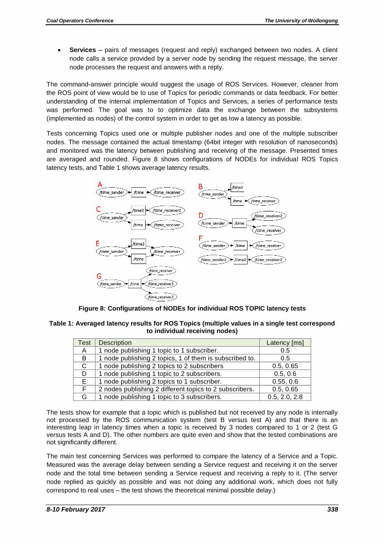
Tests concerning Topics used one or multiple publisher nodes and one of the multiple subscriber
nodes. The message contained the actual timestamp (64bit integer with resolution of nanoseconds)
and monitored was the latency between publishing and receiving of the message. Presented times
are averaged and rounded. Figure 8 shows configurations of NODEs for individual ROS Topics
latency tests, and Table 1 shows average latency results.
Figure 8: Configurations of NODEs for individual ROS TOPIC latency tests
Table 1: Averaged latency results for ROS Topics (multiple values in a single test correspond to individual receiving nodes)
Test Description Latency [ms]
A 1 node publishing 1 topic to 1 subscriber. 0.5
B 1 node publishing 2 topics, 1 of them is subscribed to. 0.5
C 1 node publishing 2 topics to 2 subscribers 0.5, 0.65
D 1 node publishing 1 topic to 2 subscribers. 0.5, 0.6
E 1 node publishing 2 topics to 1 subscriber. 0.55, 0.6
F 2 nodes publishing 2 different topics to 2 subscribers. 0.5, 0.65
G 1 node publishing 1 topic to 3 subscribers. 0.5, 2.0, 2.8
The tests show for example that a topic which is published but not received by any node is internally not processed by the ROS communication system (test B versus test A) and that there is an interesting leap in latency times when a topic is received by 3 nodes compared to 1 or 2 (test G versus tests A and D). The other numbers are quite even and show that the tested combinations are not significantly different.
The main test concerning Services was performed to compare the latency of a Service and a Topic.
Measured was the average delay between sending a Service request and receiving it on the server
node and the total time between sending a Service request and receiving a reply to it. (The server
node replied as quickly as possible and was not doing any additional work, which does not fully
correspond to real uses – the test shows the theoretical minimal possible delay.)

Coal Operators Conference The University of Wollongong
8-10 February 2017 339
ROS offers also a Persistent service, where a permanent connection between a client and server
node is established, which is useful if a lot of Service calls are expected between two particular
nodes. This option was tested the same way as standard Services. Table 2 provides average latency
results for ROS services.
Table 2: Averaged latency results for ROS services
Service Measured value Latency [ms]
Standard Client – server (request only) 2.3
Client – server – client (request + reply) 7.8
Persistent Client – server (request only) 0.24
Client – server – client (request + reply) 5.1
The results show that the standard Service is much slower than a topic and thus should be avoided in
latency-critical situations. The persistent Service is extremely fast in the first phase (request), even
faster than topics; the total latency including reply is however much higher again.
CONCLUSION
TeleRescuer is an international project managed by a consortium composed of the Silesian University
of Technology (Poland), the VSB – Technical University of Ostrava (Czech Republic), the Universidad
Carlos III de Madrid (Spain), COPEX (Poland), SIMMERSION GMBH (Austria) and SKYTECH
RESEARCH (Poland).
This paper describes design of a control system for the mobile robot TeleRescuer. For the easy
implementation of the autonomous behaviour of the mobile robot and simple teamwork across
international consortium, it was decided to migrate to the operating system ROS, which is designed
for usage in mobile robotics to simplify R and D software, especially in larger teams. Autonomy is
crucial in cases of loss of communication with the operator, because it will be able to drive the robot
back and try to re-acquire the signal.
Structure of the control system was completely re-designed for ROS. For a better understanding of
the internal implementation of the ROS communication a series of performance tests were performed,
in order to be able to better optimize the design of the individual subsystems and the communication
between them. It was decided to change some aspects of the previous control system, for example
the strict command-answer principle used in communication telegrams (TCP/IP) was replaced in most
cases with one-directional streams of data (ROS Topics).
The robot can be controlled remotely via optical fibre (primary line) or wirelessly (backup line).
Specialized software (Moczulski, et al, 2014) is used for virtual teleportation. More detailed
information about TeleRescuer subsystems of 3D map building and 3D map visualization are
described in the Midterm Report (Timofiejczuket et al, 2016; Kot, et al, 2016a; Olivka, et al, 2016a;
Moczulski, et al, 2016).
ACKNOWLEDGEMENT
The authors thank the European Commission - Research Fund for Coal and Steel for supporting this
project “System of the mobile robot TELERESCUER for inspecting coal mine areas affected by
catastrophic events”, No. RFCR-CT-2014-00002.
REFERENCES
Babjak, J, Novák, P, Kot, T and Moczulski, W, 2016. Control system of a mobile robot for coal mines. In Proceedings of the 2016 17th International Carpathian Control Conference, ICCC 2016, pp: 17-20, ISBN 978-146738606-7.

Coal Operators Conference The University of Wollongong
8-10 February 2017 340
Gao, J, Gao, X, Zhu, J, Zhu W, Wei, B, Wang, S, 2009. Coal mine detect and rescue robot technique research in Proceedings of the 2009 IEEE International Conference on Information and Automation, June 22 -25, Zhuhai/Macau, China.
Jonathon, C R, David W, Hainsworth, 1998. The numbat: a remotely controlled mine emergency response vehicle, Field and Service Robotics, pp: 53-59, ISBN 978-1-4471-1273-0.
Kasprzyczak, L, Szwejkowski, P and Cader, M, 2016. Robotics in mining exemplified by Mobile Inspection Platform pp: 23- 28, Mining – Informatics, Automation and Electrical Engineering, Volume 2 (526), Poland, ISSN 2449-6421.
Kasprzyczak, L, Trenczek, S and Cader, M, 2012. Robot for monitoring hazardous environments as a mechatronic product. Journal of Automation, Mobile Robotics and Intelligent Systems, Vol 6, N 4 2012, pp: 57-64, Poland, ISSN 1897-8649.
Kot, T, Krys, V, Mostýn, V and Novák, P, 2014. Control system of a mobile robot manipulator in Proceedings of the 2014 15th International Carpathian Control Conference, ICCC 2014 pp: 258-263. ISBN 978-1-47-993528-4.
Kot, T, Novák, P and Babjak, J, 2016a. Visualization of point clouds built from 3D scanning in coal mines in Proceedings of the 17th IEEE International Carpathian Control Conference, ICCC 2016 pp: 372-377. ISBN 978-146738606-7.
Kot, T, Novák, P, Babjak, J and Olivka, P, 2016b. Rendering of 3D maps with additional information for operator of a coal mine mobile robot in Proceedings of Modelling and Simulation for Autonomous Systems. International Workshop, MESAS 2016, p: 12, Rome, Italy, June 15-16.
Moczulski, W, Cyran, K, Januszka, M and Novák, P, 2016. TeleRescuer - An innovative robotised system for supporting mining rescuers by inspecting roadways affected by catastrophes in Proceedings of the 24th World Mining Congress, Automation and Robotics. 24th, Rio de Janeiro, Brasil : Instituto Brasileiro de Mineracao, 2016 pp: 94-103.
Moczulski, W, Cyran, K, Novak, P, Rodriguez, A and Januszka, M, 2014. TeleRescuer - A concept of a system for teleimmersion of a rescuer to areas of coal mines affected by catastrophes in Proceedings of the VI Międzynarodowa Konferencja Systemy Mechatroniczne Pojazdów i Maszyn Roboczych (in Polish).
Moczulski, W, Cyran, K, Januszka, M, Mostyn, V, Novak, P and Rodriguez, A, 2014. System for virtual TELEportation of RESCUER for inspecting coal mine areas affected by catastrophic events. TECHNICAL ANNEX of the project application p: 22
Novák, P, Babjak, J, Kot, T and Olivka, P, 2014. Exploration mobile robot for coal mines in Modelling and Simulation for Autonomous Systems. International Workshop, MESAS 2015 , Prague, Czech Republic, April 29-30, pp: 209-215, ISBN 978-3-319-22383-4.
Olivka, P, Mihola, M, Novak, P, Kot, T and Babjak, J, 2016a. The design of 3D laser range finder for robot navigation and mapping in Industrial Environment with Point Clouds Preprocessing. In Modelling and Simulation for Autonomous Systems. International Workshop, MESAS 2016 p: 13 Rome, Italy, June 15-16.
Olivka, P, Mihola, M, Novak, P, Kot, T and Babjak, J, 2016b. The 3D laser range finder design for the navigation and mapping for the coal mine robot in 17th IEEE International Carpathian Control Conference, ICCC 2016. 2016. Pp: 533-538, SCOPUS, DOI: 10.1109/CarpathianCC.2016. 7501155, ISBN 978-146738606-7.
Telerescuer, 2016. Available from <http://telerescuer.eu> [Accessed: 27 September 2016].
Timofiejczuk, A, Adamczyk, M, Moczulski, W, Mura, G and Nocoň, M, 2015. Uklad mobilny specjalistycznego robota do inspekcji wyrobisk kopalmianych dotknietych katastrofa,. Monografia: Mechanizacja, Automatyzacja i Robotyzacja w gornictwie.Krakow, ISBN 978-83-936657-7-8, pp: 66-74 (in Polish).
Timofiejczuk, A, Adamczyk, M, Moczulski, W, Januszka, M, Mura, G, Nocoň, M, Novák, P, Olivka, P, Kot, T and Cyran, K, 2016. System for virtual TELEportation of RESCUER for inspecting coal mine areas affected by catastrophic events. Mid-Term Report European Commission Research Programme of the Research Fund for Coal and Steel Technical Group: TGC1.
Wang, W, Dong, W, Su, Y, Wu, D and Du, Z, 2014. Development of search‐and‐rescue robots for underground coal mine applications, Journal of Field Robotics, Volume 31, Issue 3 pp: 386-407.