Embed Size (px)
Citation preview

TelephonyArchitecture:1 For UPnP Version 1.0 Status: Standardized DCP (SDCP) Date: March 22, 2011 Document Version: 1.0 Service Template Version: 2.00 This Standardized DCP has been adopted as a Standardized DCP by the Steering Committee of the UPnP Forum, pursuant to Section 2.1(c)(ii) of the UPnP Forum Membership Agreement. UPnP Forum Members have rights and licenses defined by Section 3 of the UPnP Forum Membership Agreement to use and reproduce the Standardized DCP in UPnP Compliant Devices. All such use is subject to all of the provisions of the UPnP Forum Membership Agreement.
THE UPNP FORUM TAKES NO POSITION AS TO WHETHER ANY INTELLECTUAL PROPERTY RIGHTS EXIST IN THE STANDARDIZED DCPS. THE STANDARDIZED DCPS ARE PROVIDED "AS IS" AND "WITH ALL FAULTS". THE UPNP FORUM MAKES NO WARRANTIES, EXPRESS, IMPLIED, STATUTORY, OR OTHERWISE WITH RESPECT TO THE STANDARDIZED DCPS, INCLUDING BUT NOT LIMITED TO ALL IMPLIED WARRANTIES OF MERCHANTABILITY, NON-INFRINGEMENT AND FITNESS FOR A PARTICULAR PURPOSE, OF REASONABLE CARE OR WORKMANLIKE EFFORT, OR RESULTS OR OF LACK OF NEGLIGENCE. Copyright © 2011 UPnP Forum. All rights Reserved. Authors1 Company
Mahfuzur Rahman (Editor) Samsung
Yoshiki Nishikawa NTT
Jeyoung Maeng Samsung
Enrico Grosso Telecom Italia 1 The UPnP forum in no way guarantees the accuracy or completeness of this author list and in no way implies any rights for or support from those members listed. This list is not the specifications’ contributor list that is kept on the UPnP Forum’s website.

Copyright © 2011 UPnP Forum. All rights Reserved.
Contents Contents.......................................................................................................................................................... 2
List of Tables .................................................................................................................................................. 3
List of Figures ................................................................................................................................................ 4
1 Overview and Scope ............................................................................................................................... 5 1.1 Notation ............................................................................................................................................. 5 1.2 References ......................................................................................................................................... 6
1.2.1 Informative References .............................................................................................................. 6 1.3 Terms and Abbreviations .................................................................................................................. 6
1.3.1 Abbreviations ............................................................................................................................. 6 1.3.2 Terms ......................................................................................................................................... 6
2 Introduction ............................................................................................................................................ 8
3 Telephony Reference Architecture ....................................................................................................... 9 3.1 Telephony Basic Architecture Paradigm ........................................................................................... 9 3.2 Telephony Components Overview .................................................................................................. 11
3.2.1 Call Management Service ........................................................................................................ 12 3.2.2 Media Management Service ..................................................................................................... 13 3.2.3 Interaction of Media and Call Management Service ................................................................ 14 3.2.4 Messaging Service ................................................................................................................... 14 3.2.5 Phone Management via Data Model ........................................................................................ 15 3.2.6 InputConfig Service ................................................................................................................. 16 3.2.7 Security .................................................................................................................................... 16
Appendix A. Deployment Scenarios ..................................................................................................... 18 A.1 Intended Deployment Scenarios ..................................................................................................... 18
A.1.1 TV With a Telephony Control Point ........................................................................................ 18 A.1.2 TV With a Telephony Control point (TelCP) and a Telephony Client (TC) ........................... 19 A.1.3 Phone With a Telephony Control Point and Telephony Server ............................................... 20 A.1.4 Phone With a Telephony Control Point ................................................................................... 21 A.1.5 A Telephony Control Point Outside of a Device with no Telephony Client and Server ......... 22 A.1.6 Messaging Service Deployment ............................................................................................... 23 A.1.7 Multiple Telephony Servers in a Telephone ............................................................................ 24

Copyright © 2011 UPnP Forum. All rights Reserved.
List of Tables Table 1-2: Abbreviations ...................................................................................................................... 6
Copyright © 2011 UPnP Forum. All rights Reserved.
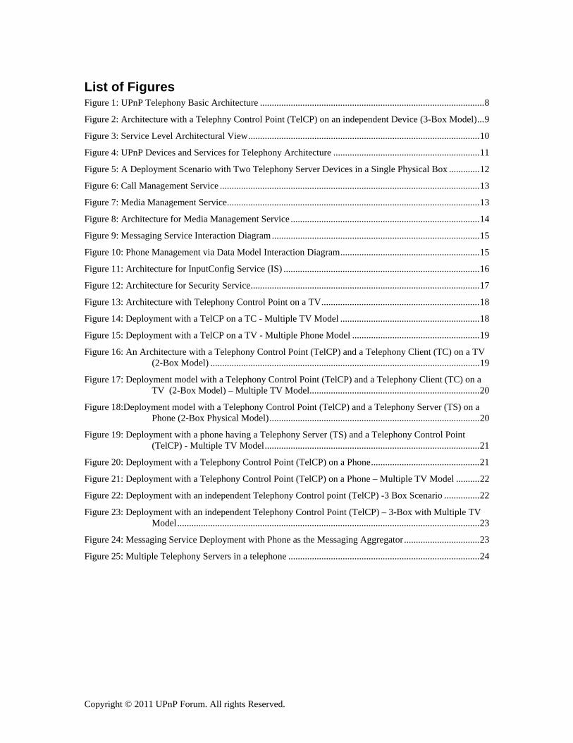
List of Figures Figure 1: UPnP Telephony Basic Architecture ............................................................................................... 8
Figure 2: Architecture with a Telephny Control Point (TelCP) on an independent Device (3-Box Model) ... 9
Figure 3: Service Level Architectural View .................................................................................................. 10
Figure 4: UPnP Devices and Services for Telephony Architecture .............................................................. 11
Figure 5: A Deployment Scenario with Two Telephony Server Devices in a Single Physical Box ............. 12
Figure 6: Call Management Service .............................................................................................................. 13
Figure 7: Media Management Service........................................................................................................... 13
Figure 8: Architecture for Media Management Service ................................................................................ 14
Figure 9: Messaging Service Interaction Diagram ........................................................................................ 15
Figure 10: Phone Management via Data Model Interaction Diagram ........................................................... 15
Figure 11: Architecture for InputConfig Service (IS) ................................................................................... 16
Figure 12: Architecture for Security Service ................................................................................................. 17
Figure 13: Architecture with Telephony Control Point on a TV ................................................................... 18
Figure 14: Deployment with a TelCP on a TC - Multiple TV Model ........................................................... 18
Figure 15: Deployment with a TelCP on a TV - Multiple Phone Model ...................................................... 19
Figure 16: An Architecture with a Telephony Control Point (TelCP) and a Telephony Client (TC) on a TV (2-Box Model) .................................................................................................................. 19
Figure 17: Deployment model with a Telephony Control Point (TelCP) and a Telephony Client (TC) on a TV (2-Box Model) – Multiple TV Model ........................................................................ 20
Figure 18:Deployment model with a Telephony Control Point (TelCP) and a Telephony Server (TS) on a Phone (2-Box Physical Model) ......................................................................................... 20
Figure 19: Deployment with a phone having a Telephony Server (TS) and a Telephony Control Point (TelCP) - Multiple TV Model ........................................................................................... 21
Figure 20: Deployment with a Telephony Control Point (TelCP) on a Phone .............................................. 21
Figure 21: Deployment with a Telephony Control Point (TelCP) on a Phone – Multiple TV Model .......... 22
Figure 22: Deployment with an independent Telephony Control point (TelCP) -3 Box Scenario ............... 22
Figure 23: Deployment with an independent Telephony Control Point (TelCP) – 3-Box with Multiple TV Model ................................................................................................................................ 23
Figure 24: Messaging Service Deployment with Phone as the Messaging Aggregator ................................ 23
Figure 25: Multiple Telephony Servers in a telephone ................................................................................. 24

Copyright © 2011 UPnP Forum. All rights Reserved.
1 Overview and Scope This document describes an architecture that allows UPnP Telephony devices, services and control points defined in the propoded DCP to be deployed in the home network environment and to enable management of incoming and outgoing telephony calls, messaging, presence information and phone features configuration through UPnP means from devices within the home.
In order to accommodate the above mentioned goals, the Telephony Architecture defines several UPnP devices and services that can be embedded to the devices defined for telephony. The architecture model describes interaction among the telephony devices, services and control points. The architecture also describes various deployment scenarios.
The architecture does not describe any interfaces to “service” gateways that will enable non-UPnP entities to interact with the UPnP devices, services and control points physically attached to the home network.
1.1 Notation • In this document, features are described as Required, Recommended, or Optional as follows:
The key words “MUST,” “MUST NOT,” “REQUIRED,” “SHALL,” “SHALL NOT,” “SHOULD,” “SHOULD NOT,” “RECOMMENDED,” “MAY,” and “OPTIONAL” in this specification are to be interpreted as described in [RFC 2119].
In addition, the following keywords are used in this specification:
PROHIBITED – The definition or behavior is an absolute prohibition of this specification. Opposite of REQUIRED.
CONDITIONALLY REQUIRED – The definition or behavior depends on a condition. If the specified condition is met, then the definition or behavior is REQUIRED, otherwise it is PROHIBITED.
CONDITIONALLY OPTIONAL – The definition or behavior depends on a condition. If the specified condition is met, then the definition or behavior is OPTIONAL, otherwise it is PROHIBITED.
These keywords are thus capitalized when used to unambiguously specify requirements over protocol and application features and behavior that affect the interoperability and security of implementations. When these words are not capitalized, they are meant in their natural-language sense.
• Strings that are to be taken literally are enclosed in “double quotes”.
• Words that are emphasized are printed in italic.
• Keywords that are defined by the UPnP Working Committee are printed using the forum character style.
• Keywords that are defined by the UPnP Device Architecture are printed using the arch character style.
• A double colon delimiter, “::”, signifies a hierarchical parent-child (parent::child) relationship between the two objects separated by the double colon. This delimiter is used in multiple contexts, for example: Service::Action(), Action()::Argument, parentProperty::childProperty.

Copyright © 2011 UPnP Forum. All rights Reserved.
1.2 References
1.2.1 Informative References This section lists the informative references that are provided as information in helping understand this specification:
[DEVICE] – UPnP Device Architecture, version 1.0. Available at: http://www.upnp.org/specs/arch/UPnP-arch-DeviceArchitecture-v1.0-20080424.pdf. Latest version available at: http://www.upnp.org/specs/arch/UPnP-arch-DeviceArchitecture-v1.0.pdf.
[DEVICE-IPv6] – UPnP Device Architecture, version 1.0., Annex A – IP Version 6 Support. Available at: http://www.upnp.org/resources/documents/AnnexA-IPv6_000.pdf
[RFC 2119] – S. Bradner, RFC 2119: Key words for use in RFCs to Indicate Requirement Levels, 1997. Available at: http://www.faqs.org/rfcs/rfc2119.html.
[CONVENTIONS] – UPnP-tech-NamingConventions-v2-20071010.pdf Available at: https://members.upnp.org/default.asp?ItemType=Doc&ItemID=7005
1.3 Terms and Abbreviations
1.3.1 Abbreviations
Table 1-2: Abbreviations
Definition Description
TS Telephony Server
TC Telephony Client
TelCP Telephony Control Point
InputConfig InputConfig Service
ICP Input Control Point
1.3.2 Terms
1.3.2.1 Telephony Server (TS) The term Telephony Server (TS) refers to a logical device that provides common telephony features (e.g. call/video call, messaging, address book) via UPnP to other devices in the home network. A TS is usually connected to a telephony service on its WAN interface, either wire line or mobile. For example, a TS may be a mobile phone or a home gateway with VoIP features.
1.3.2.2 Telephony Client (TC) The term Telephony Client (TC) to a networked logical device that allows the user to enjoy the telephony features provided by the Telephony Server via UPnP. A TC may usually provide input/output features for voice and video. An example of a TC is a networked TV Set.
1.3.2.3 Telephony Control Point (TelCP) The term Telephony Control Point (TelCP) refers to a software feature able to control the functionalities of both TS and TC. It may be embedded in a TS, a TC or also being a physical device on its own.

Copyright © 2011 UPnP Forum. All rights Reserved.
1.3.2.4 InputConfig Control Point (ICP) The Term InputConfig Control Point (ICP) refers to a software feature that is able to control the functionalities of UPnP devices to be used to provide user-friendly input features. The control here refers to getting capabilities of UPnP dveices to be used for input, matching capabilities and selecting the appropriate dveice role such as receving side or sending side etc.
1.3.2.5 InputConfig Service (IS) The Term InputConfig Service (InputConfig) refers to a software feature that is able to provide user-friendly input capability via UPnP means and expose interfaces to describe capabilities of sender/receiver of devices to be used for input services and setup the input session between the devices using the matching profile (capability) from the ICP .
Copyright © 2011 UPnP Forum. All rights Reserved.
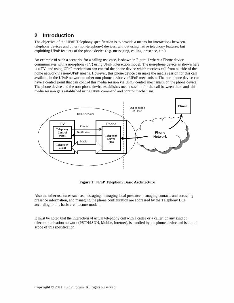
2 Introduction The objective of the UPnP Telephony specification is to provide a means for interactions between telephony devices and other (non-telephony) devices, without using native telephony features, but exploiting UPnP features of the phone device (e.g. messaging, calling, presence, etc.). An example of such a scenario, for a calling use case, is shown in Figure 1 where a Phone device communicates with a non-phone (TV) using UPnP interaction model. The non-phone device as shown here is a TV, and using UPnP mechanism can control the phone device which receives call from outside of the home network via non-UPnP means. However, this phone device can make the media session for this call available in the UPnP network to other non-phone device via UPnP mechanism. The non-phone device can have a control point that can control this media session via UPnP control mechanism on the phone device. The phone device and the non-phone device establishes media session for the call between them and this media session gets established using UPnP command and control mechanism.
Media
Notification
Control Phone
Telephony
Server (TS)
TV
Telephony Client
Telephony Control
Point
Home Network
Phone
Phone Network
Out of scope of UPnP
Figure 1: UPnP Telephony Basic Architecture
Also the other use cases such as messaging, managing local presence, managing contacts and accessing presence information, and managing the phone configuration are addressed by the Telephony DCP according to this basic architecture model.
It must be noted that the interaction of actual telephony call with a callee or a caller, on any kind of telecommunication network (PSTN/ISDN, Mobile, Internet), is handled by the phone device and is out of scope of this specification.

Copyright © 2011 UPnP Forum. All rights Reserved.
3 Telephony Reference Architecture
3.1 Telephony Basic Architecture Paradigm This section of the document describes the basic architectural model for telephony features.
The basic architecture for UPnP telephony features can be described in a 3-box model which is shown below in Figure 2. . Figure 2 represents a 3-box model where the Telephony Control Point (TelCP) resides on a box outside of the Telephony Server (TS) and the Telephony Client (TC). The Telephony Control Point (TelCP) discovers both the Telephony Client (TC) and the Telephony Server (TS) and can establish the media session between them. And can control the media session between the Telephony Client (TC) and the Telephony Server (TS). This model can be collapsed into a 2-box model by having the Telephony Control Point (TelCP) reside either in the Telephony Server (TS) or the Telephony Client (TC). The Telephony Control Point (TelCP) can also directly interact with the Telephony Server (TS) without needing an interaction with a Telephony Client (TC) or without residing in the Telephony Client (TC). This is the case when realizing a number of features such as presence and messaging services, notifications, initiating a call etc.
Notification Notification
Media/Data
Control
Phone
TelephonyServer (TS)
TV
Telephony
Client (TC)
PDA Telephony
Control Point
(TelCP)Control
Figure 2: Architecture with a Telephny Control Point (TelCP) on an independent Device (3-Box Model)
The diagram below shows a more detailed view on the interactions between a Telephony Control Point (TelCP), a Telephony Server (TS) and a Telephony Client (TC). The Telephony Server (TS) and the Telephony Client (TC) are UPnP devices. A Telephony Client (TC) and a Telephony Server (TS) devices consists of a set of services and the Telephony Control Point (TelCP) basically interacts with the services using UPnP actions. The actual communication between TC and TS devices for media streams is performed out-of-band with respect to UPnP protocols.

Copyright © 2011 UPnP Forum. All rights Reserved.
Telephony Control Point (UI Application)
Telephony Server …..
Telephony Client …..
Bi-directionalMedia transfer
Standard UPnP Actions
Input Service
Media Management Service
Input Service
Media Management Service
Media Transfer Server/Client
Media Transfer Server/ Client
Figure 3: Service Level Architectural View
The diagram above shows the service level interaction model using UPnP actions. The various services as defined for the telephony featuures expose interfaces forthe Telephony Control Point (TelCP) to access those services.

Copyright © 2011 UPnP Forum. All rights Reserved.
3.2 Telephony Components Overview This section of the document provides an overview of the Telephony architecture components in terms of UPnP devices and UPnP services that this Telephony specification defines. The architecture defines two different UPnP devices: Telephony Server (TS) Device and Telephony Client (TC) Device. There are a number of UPnP services that are defined which include: Media Management Service, Call Management Service, Messaging Service, Presence Service, Phone Management via Data Model and UPnP Device Management, Input Service, and Security Service.
UPnP TC Device Media Management
Service
Input Service
Device Protection Service
UPnP TS DeviceCall Management
Service
Messaging Service
CMS Service
Input Service
Device Protection Service
Messaging Service
Phone Data Model
Figure 4: UPnP Devices and Services for Telephony Architecture
The types of services a Telephony Server (TS) Device and a Telephony Client (TC) Device may include is shown in Figure 4.
• The Media Management Service resides in a Telephony Client (TC) device and is responsible to establish and manage media session on the client side.
• The Call Management service resides in the Telephony Server (TS) device and is responsible for establishing and real-time controlling call and media session on the server side.
• The Messaging service can reside in the Telephony Server (TS) device or the Telephony Client (TC) device.
• Phone management on the TS-side is performed via the reuse of the Configuration Management Service (CMS), as specified by UPnP Device Management, and a specific data model defined by UPnP Telephony.
• The Input Service due to its symmetrical nature will reside in both Telephony Server (TS) Device and Telephony Client (TC) Device.
• Security is achieved by reusing on both TS and TC the DeviceProtection service, as specified by the Gayeway WC, with a ad hoc profiling for the Telephony WC.

Copyright © 2011 UPnP Forum. All rights Reserved.
The figure below shows a deployment scenario where two Telephony Server devices are residing in a single physical box. This kind of deployment model will allow having multiple telephony identities in a single physical box with each identity representing a telephone number. A Telephony Server (TS) will advertise its identity in the device description document. Indeed these two TS devices could be embedded in a root UPnP Basic device as shown in the Figure below.. This Figure represents that the two UPnP TS devices are logical functions of a unique telephone.
UPnP TS Device Call Management
Service
Messaging Service
CMS Service
Input Service
Device Protection Service
Phone Data Model
UPnP TS DeviceCall Management
Service
Messaging Service
CMS Service
Input Service
Device Protection Service
Phone Data Model
Single Physical Device UPnP Basic Device
Figure 5: A Deployment Scenario with Two Telephony Server Devices in a Single Physical Box
3.2.1 Call Management Service The Call Management Service is responsible to enable the features for a Telephony Control Point (TelCP) to initiate a call, accept or connect an incoming call or receive notifications for incoming calls and manage media session associated with the call including starting and stoping the media session.. The high-level interaction between the Call Management Service in a Telephony Server (TS) and a Telephony Control Point (TelCP) is shown below. These interactions involve a number of interfaces exposed by the Call Mangement Service and the Telephony Control Point (TelCP) uses those interfaces to initiate a call or accept or reject or modify an incoming call. The Call Management service also includes interfaces to manage media session including starting and stoping of media transfer on the server side, and getting media capabilitities of the server. The interactions also involve eventing mechanism where notifications for incoming call are sent from the Telephony Server (TS) to the Telephony Control Point (TelCP) through the Call Management Service.

Copyright © 2011 UPnP Forum. All rights Reserved.
Telephony Server (TS)
Telephony Control Point
(TelCP)
Notification for incoming calls
Initiate/Stop/Reject a Call
Call Management
Service Manage a call (modify call)
Manage media session (start/stop media transfer, getting media capabilities)
Figure 6: Call Management Service
3.2.2 Media Management Service The Media Management Service provides the feature to set-up media session on a Telephony Client (TC), under the control of a Telephony Control Point (TelCP). The architectural model shown in the diagram below at a very high level explains how media session parameters are gathered/negotiated by a Telephony Control Point (TelCP) to establish a media session between a Telephony Server (TS) and a Telephony Client (TC). The more details of the negotiations of media capabilities are explained in the next section.
Telephony Client (TC)
Telephony Control Point
(TelCP)
GetMediaCapabilities
Media Management
Service GetMediasessionInfo
Manage media session (start/stop media session)
Figure 7: Media Management Service

Copyright © 2011 UPnP Forum. All rights Reserved.
3.2.3 Interaction of Media and Call Management Service The Telephony Server and the Telephony Client (TC) expose interface for a Telephony Control Point (TelCP) to retrieve the media capabilities of the server and the client. Once the media capabilities are gathered and matched by the Telephony Control Point (TelCP), the Telephony Control Point (TelCP) starts the media session by invoking actions exposed by the Telephony Server (TS) and the Telephony Client (TC).
Figure 8: Architecture for Media Management Service
The figure above describes the basic flow of the sequence to establish media session between a Telephony Server (TS) and a Telephony Client (TC). The diagram shows a 3-box scenario. However, the location of the control point can be anywhere including in the Telephony Server (TS) or the Telephony Client (TC). When the Telephony Control Point (TelCP) resides in the Telephony Server (TS) or in the Telephony Client (TC), the interaction between the server or the client where the control point resides will be through internal interface. A Telephony Control Point (TelCP) can initiate the media session establishment process from either end (TS or TC). The figure above only shows one possible approach. The interactions between the TelCP and TS or the TC are through UPnP actions.
3.2.4 Messaging Service The basic architecture for the messaging service can be envisioned as the interactions between a Telephony Server (TS), or a Telephony Client (TC), with a Telephony Control point (TelCP). The figure below shows the basic architecture for the Messaging service.
It is assumed that the end user functions for managing messages are provided by a user terminal implementing the TelCP.
Telephony Server (TS)
Telephony Control Point
(TelCP)
Get Media Session
Capabilities
Get Media Session
Capabilities
12
4
Media
3Start Media
Transfer
Stop Media transfer
6
5
Stop Media session
Start Media Session
Telephony Client (TC)

Copyright © 2011 UPnP Forum. All rights Reserved.
Telephony Server (TS) or
Telephony Client (TC)
Telephony Control Point
(TelCP) Notification for message
Send/Retrieve message
Messaging
Service
Figure 9: Messaging Service Interaction Diagram
The basic architecture for Messaging service requires basic UPnP eventing mechanism for notifications of incoming messages. The interactions between Telephony Control Point (TelCP) and the Messaging service also requires a number of UPnP actions to realize the features of messaging service.
3.2.5 Phone Management via Data Model The basic software architecture for the support of functionalities for configuration management of the Telephony Server (TS), via a set of configuration parameters (i.e. the “Telephony Server Data Model”), is shown in the figure below.
Figure 10: Phone Management via Data Model Interaction Diagram
This architecture assumes that UPnP Device Management (DM) is reused as follows:
• A Telephony Server (TS) device may include a Confiramtion Management Service (CMS) as defined in the DM:1.
Telephony Server (TS)
ConfigurationManagement Service (CMS)
Phone
Data Model
TelephonyControl
Point (TelCP)
Get/Set values of parameters in the TS data model(i.e. TS Configuration
Management)
Notifications of configuration change

Copyright © 2011 UPnP Forum. All rights Reserved.
• The CMS service allows the manipulation of configuration parameters, both for retrieving configuration and status information from a managed device (here the TS device) or for changing its configuration; notifications of configuration updates are also available;
• The UPnP Telephony architecture assumes that a Data Model for the TS is defined, both including generic device parameters, as specified in UPnP DM CMS service, and specific additional parameters for managing the TS features (e.g. manipulating address book with contacts, accessing lists of calls, setting ringtones).
Finally, the Telephony Control Point (TelCP) will include also the capability of control point for UPnP DM.
3.2.6 InputConfig Service The InputConfig Service (IS) provides a feature for user-friendly input capability setup via UPnP means. The sender and receiver devices MUST have this service in order to facilitate such user friendly input capability. The architecture for the Input Service (IS) is shown below.
Mobile Phone TV
InputConfigControl Point
InputConfig Service
InputConfig Service
Get Input Capability Get Input Capability
Set Up Input Session
Set Up Input Session
Start/Stop Input Session
Figure 11: Architecture for InputConfig Service (IS) The above architecture shows a 3-box model where a Input Control Point (ICP) resides on a device other than the sender and receiving device with Input Service (IS). However, the Input Control Point (ICP) can reside in either of the devices due to the symmetrical nature of the service. The Input Control Point (ICP) retrieves input capability information of the devices by invoking action exposed by the input Service (IS) and does the capability matching to select and setup the appropriate role for the devices (which include sender or receiving role, input type, etc) and the protocol for exchanging input data. The actual transfer of input data occurs in out of band mechanism (i.e. the protocols for exchanging input data are not based on the UPnP protocol stack, UDA).
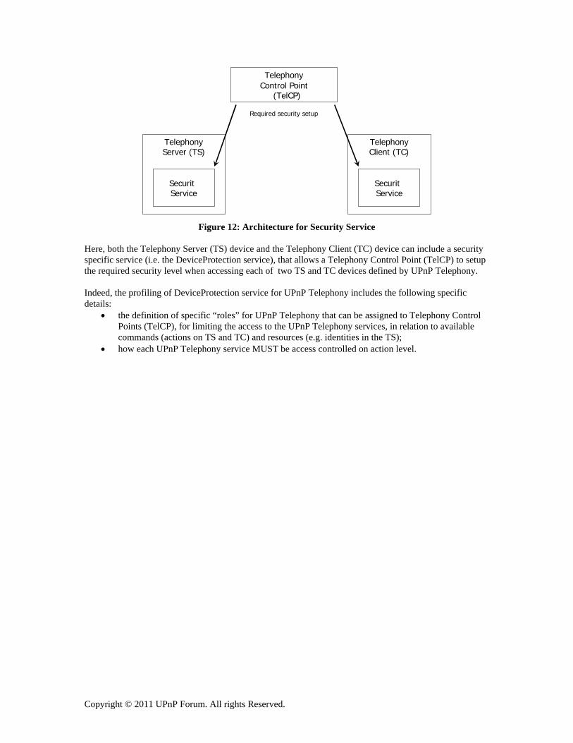
3.2.7 Security According to the specification of the security solution for UPnP IGD:2, the security solution for UPnP Telephony reuses the DeviceProtection service specified in IGD:2, as shown in the following figure.
Copyright © 2011 UPnP Forum. All rights Reserved.
Figure 12: Architecture for Security Service
Here, both the Telephony Server (TS) device and the Telephony Client (TC) device can include a security specific service (i.e. the DeviceProtection service), that allows a Telephony Control Point (TelCP) to setup the required security level when accessing each of two TS and TC devices defined by UPnP Telephony. Indeed, the profiling of DeviceProtection service for UPnP Telephony includes the following specific details:
• the definition of specific “roles” for UPnP Telephony that can be assigned to Telephony Control Points (TelCP), for limiting the access to the UPnP Telephony services, in relation to available commands (actions on TS and TC) and resources (e.g. identities in the TS);
• how each UPnP Telephony service MUST be access controlled on action level.
TelephonyServer (TS)
SecuritService
TelephonyClient (TC)
Required security setup
SecuritService
TelephonyControl Point
(TelCP)

Copyright © 2011 UPnP Forum. All rights Reserved.
Appendix A. Deployment Scenarios
A.1 Intended Deployment Scenarios
A.1.1 TV With a Telephony Control Point Figure below shows a model where a Telephony Control Point (TelCP) resides on a TV and the Telephony Server (TS) resides on a phone. This model can realize a number of use cases including presence of contacts, presence updated by the control point, initiating a call, notifications, etc. In case of presence of contacts, the Telephony Control Point (TelCP), that resides on the TV, can invoke an action to retrieve the presence information of the contact of interest and also the same applies while updating presence at the telephony Server (TS). The telephony Server (TS) can notify to the Telephony Control Point (TelCP) on the TV about any incoming call or a notify call-back. This is one of the very basic architectural models and, however, with this model it is not possible to establish a media session since there is no Telephony Client (TC) on the TV that can have a media session with the Telephony Server (TS) on the phone.
Notification
Control Phone Telephony Server (TS)
TV Telephony
Control Point
(TelCP)
Figure 13: Architecture with Telephony Control Point on a TV
Figure below shows another deployment model for the model described above. In the scenario below, the Telephony Server (TS) is communication with multiple Telephony Control Points (TelCP). Besides being controlled by multiple telephony Control Points (TelCP), possibly concurrently, it is basically the same model as described above.
Notification
Phone
TS
TV
TelCPControl
Control
Notification
TV
TelCP
Figure 14: Deployment with a TelCP on a TC - Multiple TV Model

Copyright © 2011 UPnP Forum. All rights Reserved.
Another variation of the model “Telephony Control Point (TelCP) on a TV” is the case where the telephony Control point (TelCP) on the TV can control multiple telephony Servers (TS). This is shown in Figure 8.
Notification
TV
TelCP
Phone
TS Control
Control
Notification
Phone
TS
Figure 15: Deployment with a TelCP on a TV - Multiple Phone Model
A.1.2 TV With a Telephony Control point (TelCP) and a Telephony Client (TC)
Figure below represents a 2-box model where the TV includes a Telephony Client (TC) and a Telephony Control Point (TelCP). The Telephony Server (TS) resides on the phone. The use cases that can be realized using this model includes call itself, which basically means establishing bi-directional media session between the Telephony Client (TC) and the Telephony Server (TS), messaging including both session and page mode, seamless handover, modifying stream on a call, etc..
Media
Notification
Control Phone
Telephony Server (TS)
TV
Telephony Client
Telephony Control
Point
Figure 16: An Architecture with a Telephony Control Point (TelCP) and a Telephony Client (TC) on a TV (2-Box Model)
A variation of the above deployment model is shown in Figure below. The Figure also shows multiple TV, each with a Telephony Control Point (TelCP) and a Telephony Client (TC), that are interacting with the Telephony Server (TS). This deployment mode is suitable to realize features such as calling using multiple devices, seamless hand-over, and modifying a stream in a call.

Copyright © 2011 UPnP Forum. All rights Reserved.
Event
Control
Media
Event
Control Phone
TS
TV
TC
TelCP
TV
TC
TelCP
Media
Figure 17: Deployment model with a Telephony Control Point (TelCP) and a Telephony Client (TC) on a TV (2-Box Model) – Multiple TV Model
A.1.3 Phone With a Telephony Control Point and Telephony Server Figure below shows a diagram where a Telephony Control Point (TelCP) and a Telephony Server (TS) reside on a phone and the Telephony Client (TC) resides on a TV. This is a 2-box physical model where the control point resides in the phone. This model can realize the feature such as call itself where a bi-directional media session is established between the Telephony Client (TC) and the Telephony Server (TS) and is controlled by the telephony Control Point (TelCP) residing in the Telephony Server (TS).
Media
Notification
Control Phone
TS
TV
TC
TelCP
Figure 18:Deployment model with a Telephony Control Point (TelCP) and a Telephony Server (TS) on a Phone (2-Box Physical Model)
A variation of the above model, where multiple Telephony Clients (TC) are interacting with the Telephony Server (TS), is shown in the Figure below. A number of features including seamless handover, modifying a stream in a call can be realized by this deployment model.

Copyright © 2011 UPnP Forum. All rights Reserved.
Notification
Control
Media
TV
TC
Media
Notification
Control
Phone
TS TV
TC
TelCP
Figure 19: Deployment with a phone having a Telephony Server (TS) and a Telephony Control Point (TelCP) - Multiple TV Model
A.1.4 Phone With a Telephony Control Point The Figure below shows a deployment model where a Telephony Control Point (TelCP) resides on a phone. This model can realize the feature such as presence updated automatically by the Telephony Client (TC).
Notification
Control Phone
TelCP
TV
TC
Figure 20: Deployment with a Telephony Control Point (TelCP) on a Phone
A derivative of the above deployment model is shown in the Figure below where multiple telephony Clients (TC) interact with the Telephony Control Point (TelCP) residing on the Phone.

Copyright © 2011 UPnP Forum. All rights Reserved.
Notification
Control Phone
TelCP
TV
TC
TV
TC
Figure 21: Deployment with a Telephony Control Point (TelCP) on a Phone – Multiple TV Model
A.1.5 A Telephony Control Point Outside of a Device with no Telephony Client and Server
This is the basic architectural model that has been described in Section 2 of this document. This model basically represents a 3-box model, where the Telephony Control Point (TelCP) resides on a box outside of the Telephony Server (TS) and the Telephony Client (TC). The Telephony Control Point (TelCP) discovers both the Telephony Client (TC) and the Telephony Server (TS) and can establish the media session between them and then can control the media session between the Telephony Client (TC) and the Telephony Server (TS).
Notification Notification
Media/Data
Control
Phone
TelephonyServer (TS)
TV
Telephony Client (TC)
PDA Telephony
Control Point
(TelCP) Control
Figure 22: Deployment with an independent Telephony Control point (TelCP) -3 Box Scenario
A variation of the above deployment model is shown in the Figure below where multiple TVs with a Telephony Client (TC) establish media session with a Telephony Server (TS). The media sessions are controlled by a stand alone Telephony Control Point (TelCP). This variation of deployment can realize features such as calling using multiple devices, seamless hand-over, and modifying a stream in a call.
Copyright © 2011 UPnP Forum. All rights Reserved.
Notification
Control
Notification
Control
Media
TV
TC
Media
Notification
Control
Phone
TS
TV
TC
TelCP
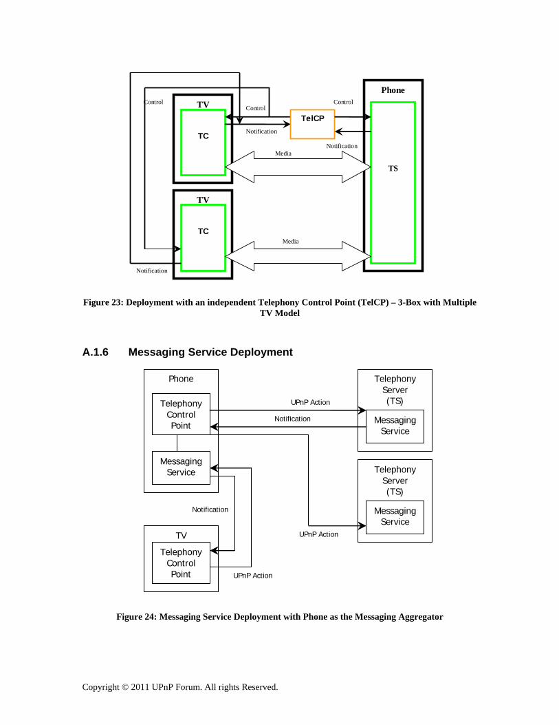
Figure 23: Deployment with an independent Telephony Control Point (TelCP) – 3-Box with Multiple TV Model
A.1.6 Messaging Service Deployment
Phone
Telephony Server (TS)
Messaging Service
Telephony Control Point
Messaging Service
Telephony Server (TS)
Messaging Service
TV Telephony
Control Point UPnP Action
UPnP Action
UPnP Action
Notification
Notification
Figure 24: Messaging Service Deployment with Phone as the Messaging Aggregator

Copyright © 2011 UPnP Forum. All rights Reserved.
The above figure shows a deployment scenario where a phone acts as the aggregator of messaging service by gathering messages information from multiple Telephony Servers (TS).
A.1.7 Multiple Telephony Servers in a Telephone A Home Gateway with VoIP functionalities (for communications, messaging, presence, …), that provides multiple VoIP lines to other devices via UPnP Telephony, can implement multiple Telephony Servers (TS), as shown in the figure below (with a Voip Gateway and two lines).
Figure 25: Multiple Telephony Servers in a telephone
Then, Telephony Control Points can enroll and use the features of the multiple Telephony Servers, in order to accommodate the end user preference: e.g. a PDA could subscribe to the VoIP gateway only for Line 1, while a TV could subscibe to both Lines.
VoIP Gateway
TS
(Line 1)
TS
(Line 2)
PDA
TelC
TV
T
TelC