Embed Size (px)
Citation preview
1
the condition monitoring magazine of PRÜFTECHNIK AG and Flender Service GmbH
No. 04 - October 2002
In this issue:PRÜFTECHNIK AG & Flender Service:The benefit of joining forces
Steel mill with automatic overloadmonitoring
Digital and software-supportedteleservice (2)
Level 1: Characteristic values of roll-er bearings
Level 2: Basic rules for themeasurement of frequency spectra
Aligning a test stand for injectioncontrollers used in Tornado engines
News & tradefair dates
Condition monitoring application:
Steel mill withautomatic overload monitoringDr.Becker, Herne
Online condition monitoring has de-veloped into the state of the art forcertain systems. At the same time, themarket shows that it is often not enoughto simply deliver a functioning systemconsisting of sensors, hardware and soft-ware. Many system operators also wantto purchase a diagnostic service in theform of telediagnosis by a competent
partner, as they do not possess the nec-essary know-how themselves. The indus-trial sector of wind-powered energy canbe cited as a typical example. A numberof respected insurance companies willonly insure the systems if certain compo-nents are replaced after a specified in-spection interval. An extension of theinterval can only be achieved by suitable
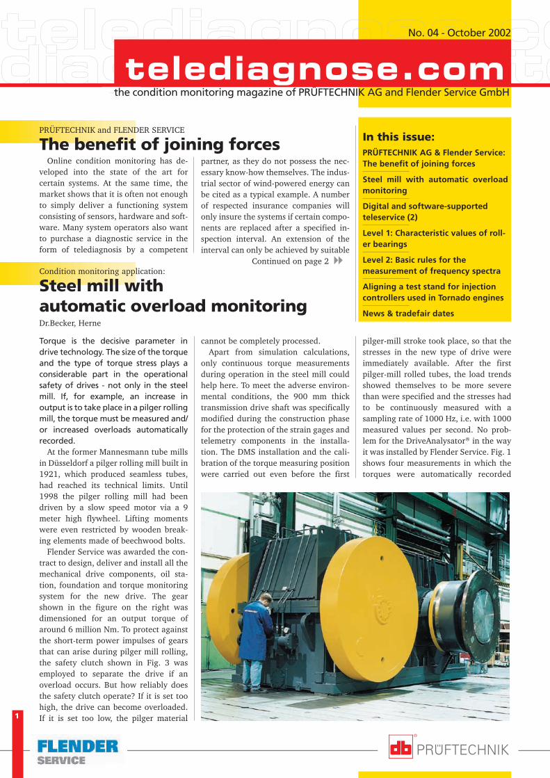
Torque is the decisive parameter indrive technology. The size of the torqueand the type of torque stress plays aconsiderable part in the operationalsafety of drives - not only in the steelmill. If, for example, an increase inoutput is to take place in a pilger rollingmill, the torque must be measured and/or increased overloads automaticallyrecorded.
At the former Mannesmann tube millsin Düsseldorf a pilger rolling mill built in1921, which produced seamless tubes,had reached its technical limits. Until1998 the pilger rolling mill had beendriven by a slow speed motor via a 9meter high flywheel. Lifting momentswere even restricted by wooden break-ing elements made of beechwood bolts.
Flender Service was awarded the con-tract to design, deliver and install all themechanical drive components, oil sta-tion, foundation and torque monitoringsystem for the new drive. The gearshown in the figure on the right wasdimensioned for an output torque ofaround 6 million Nm. To protect againstthe short-term power impulses of gearsthat can arise during pilger mill rolling,the safety clutch shown in Fig. 3 wasemployed to separate the drive if anoverload occurs. But how reliably doesthe safety clutch operate? If it is set toohigh, the drive can become overloaded.If it is set too low, the pilger material
cannot be completely processed.Apart from simulation calculations,
only continuous torque measurementsduring operation in the steel mill couldhelp here. To meet the adverse environ-mental conditions, the 900 mm thicktransmission drive shaft was specificallymodified during the construction phasefor the protection of the strain gages andtelemetry components in the installa-tion. The DMS installation and the cali-bration of the torque measuring positionwere carried out even before the first
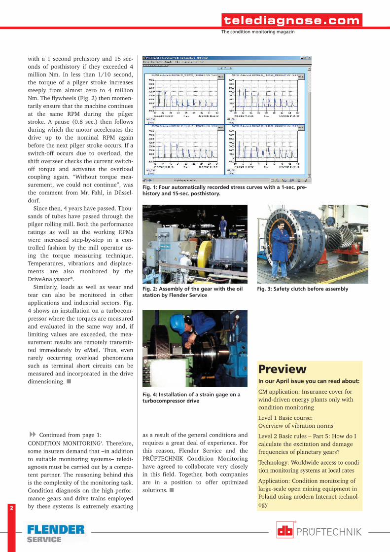
pilger-mill stroke took place, so that thestresses in the new type of drive wereimmediately available. After the firstpilger-mill rolled tubes, the load trendsshowed themselves to be more severethan were specified and the stresses hadto be continuously measured with asampling rate of 1000 Hz, i.e. with 1000measured values per second. No prob-lem for the DriveAnalysator® in the wayit was installed by Flender Service. Fig. 1shows four measurements in which thetorques were automatically recorded
PRÜFTECHNIK and FLENDER SERVICE
The benefit of joining forces
Continued on page 2 �
2
The condition monitoring magazin
with a 1 second prehistory and 15 sec-onds of posthistory if they exceeded 4million Nm. In less than 1/10 second,the torque of a pilger stroke increasessteeply from almost zero to 4 millionNm. The flywheels (Fig. 2) then momen-tarily ensure that the machine continuesat the same RPM during the pilgerstroke. A pause (0.8 sec.) then followsduring which the motor accelerates thedrive up to the nominal RPM againbefore the next pilger stroke occurs. If aswitch-off occurs due to overload, theshift overseer checks the current switch-off torque and activates the overloadcoupling again. “Without torque mea-surement, we could not continue”, wasthe comment from Mr. Fahl, in Düssel-dorf.
Since then, 4 years have passed. Thou-sands of tubes have passed through thepilger rolling mill. Both the performanceratings as well as the working RPMswere increased step-by-step in a con-trolled fashion by the mill operator us-ing the torque measuring technique.Temperatures, vibrations and displace-ments are also monitored by theDriveAnalysator®.
Similarly, loads as well as wear andtear can also be monitored in otherapplications and industrial sectors. Fig.4 shows an installation on a turbocom-pressor where the torques are measuredand evaluated in the same way and, iflimiting values are exceeded, the mea-surement results are remotely transmit-ted immediately by eMail. Thus, evenrarely occurring overload phenomenasuch as terminal short circuits can bemeasured and incorporated in the drivedimensioning. �
PreviewIn our April issue you can read about:
CM application: Insurance cover forwind-driven energy plants only withcondition monitoring
Level 1 Basic course:Overview of vibration norms
Level 2 Basic rules – Part 5: How do Icalculate the excitation and damagefrequencies of planetary gears?
Technology: Worldwide access to condi-tion monitoring systems at local rates
Application: Condition monitoring oflarge-scale open mining equipment inPoland using modern Internet technol-ogy
CONDITION MONITORING‘. Therefore,some insurers demand that –in additionto suitable monitoring systems– teledi-agnosis must be carried out by a compe-tent partner. The reasoning behind thisis the complexity of the monitoring task.Condition diagnosis on the high-perfor-mance gears and drive trains employedby these systems is extremely exacting
� Continued from page 1: as a result of the general conditions andrequires a great deal of experience. Forthis reason, Flender Service and thePRÜFTECHNIK Condition Monitoringhave agreed to collaborate very closelyin this field. Together, both companiesare in a position to offer optimizedsolutions. �
Fig. 1: Four automatically recorded stress curves with a 1-sec. pre-history and 15-sec. posthistory.
Fig. 2: Assembly of the gear with the oilstation by Flender Service
Fig. 3: Safety clutch before assembly
Fig. 4: Installation of a strain gage on aturbocompressor drive
3
The condition monitoring magazin
Roland Schühle, Mathias Luft, Franz Lebitsch
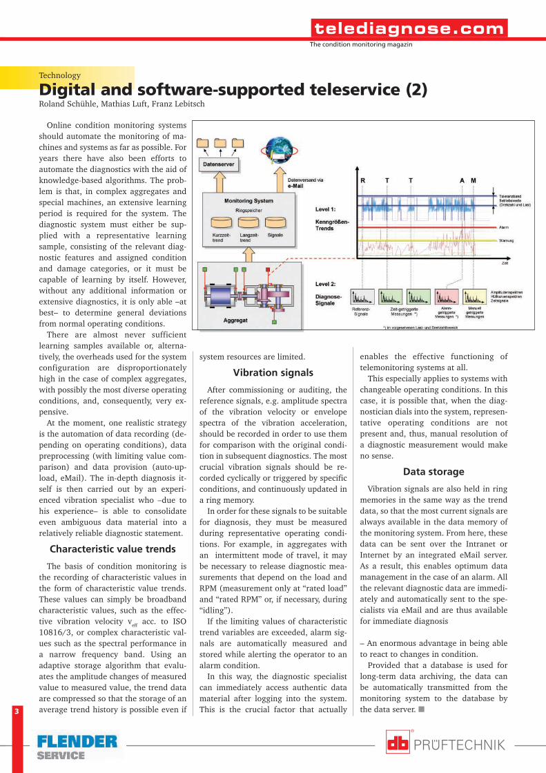
Online condition monitoring systemsshould automate the monitoring of ma-chines and systems as far as possible. Foryears there have also been efforts toautomate the diagnostics with the aid ofknowledge-based algorithms. The prob-lem is that, in complex aggregates andspecial machines, an extensive learningperiod is required for the system. Thediagnostic system must either be sup-plied with a representative learningsample, consisting of the relevant diag-nostic features and assigned conditionand damage categories, or it must becapable of learning by itself. However,without any additional information orextensive diagnostics, it is only able –atbest– to determine general deviationsfrom normal operating conditions.
There are almost never sufficientlearning samples available or, alterna-tively, the overheads used for the systemconfiguration are disproportionatelyhigh in the case of complex aggregates,with possibly the most diverse operatingconditions, and, consequently, very ex-pensive.
At the moment, one realistic strategyis the automation of data recording (de-pending on operating conditions), datapreprocessing (with limiting value com-parison) and data provision (auto-up-load, eMail). The in-depth diagnosis it-self is then carried out by an experi-enced vibration specialist who –due tohis experience– is able to consolidateeven ambiguous data material into arelatively reliable diagnostic statement.
Characteristic value trends
The basis of condition monitoring isthe recording of characteristic values inthe form of characteristic value trends.These values can simply be broadbandcharacteristic values, such as the effec-tive vibration velocity veff acc. to ISO10816/3, or complex characteristic val-ues such as the spectral performance ina narrow frequency band. Using anadaptive storage algorithm that evalu-ates the amplitude changes of measuredvalue to measured value, the trend dataare compressed so that the storage of anaverage trend history is possible even if
Technology
Digital and software-supported teleservice (2)
system resources are limited.
Vibration signals
After commissioning or auditing, thereference signals, e.g. amplitude spectraof the vibration velocity or envelopespectra of the vibration acceleration,should be recorded in order to use themfor comparison with the original condi-tion in subsequent diagnostics. The mostcrucial vibration signals should be re-corded cyclically or triggered by specificconditions, and continuously updated ina ring memory.
In order for these signals to be suitablefor diagnosis, they must be measuredduring representative operating condi-tions. For example, in aggregates withan intermittent mode of travel, it maybe necessary to release diagnostic mea-surements that depend on the load andRPM (measurement only at “rated load”and “rated RPM” or, if necessary, during“idling”).
If the limiting values of characteristictrend variables are exceeded, alarm sig-nals are automatically measured andstored while alerting the operator to analarm condition.
In this way, the diagnostic specialistcan immediately access authentic datamaterial after logging into the system.This is the crucial factor that actually
enables the effective functioning oftelemonitoring systems at all.
This especially applies to systems withchangeable operating conditions. In thiscase, it is possible that, when the diag-nostician dials into the system, represen-tative operating conditions are notpresent and, thus, manual resolution ofa diagnostic measurement would makeno sense.
Data storage
Vibration signals are also held in ringmemories in the same way as the trenddata, so that the most current signals arealways available in the data memory ofthe monitoring system. From here, thesedata can be sent over the Intranet orInternet by an integrated eMail server.As a result, this enables optimum datamanagement in the case of an alarm. Allthe relevant diagnostic data are immedi-ately and automatically sent to the spe-cialists via eMail and are thus availablefor immediate diagnosis
– An enormous advantage in being ableto react to changes in condition.
Provided that a database is used forlong-term data archiving, the data canbe automatically transmitted from themonitoring system to the database bythe data server. �
4
The condition monitoring magazin
4
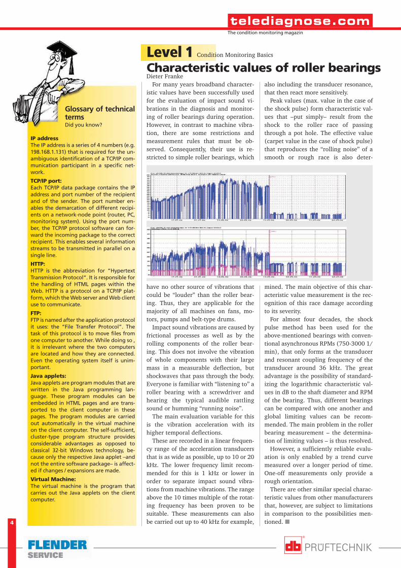
also including the transducer resonance,that then react more sensitively.
Peak values (max. value in the case ofthe shock pulse) form characteristic val-ues that –put simply– result from theshock to the roller race of passingthrough a pot hole. The effective value(carpet value in the case of shock pulse)that reproduces the “rolling noise” of asmooth or rough race is also deter-
mined. The main objective of this char-acteristic value measurement is the rec-ognition of this race damage accordingto its severity.
For almost four decades, the shockpulse method has been used for theabove-mentioned bearings with conven-tional asynchronous RPMs (750-3000 1/min), that only forms at the transducerand resonant coupling frequency of thetransducer around 36 kHz. The greatadvantage is the possibility of standard-izing the logarithmic characteristic val-ues in dB to the shaft diameter and RPMof the bearing. Thus, different bearingscan be compared with one another andglobal limiting values can be recom-mended. The main problem in the rollerbearing measurement – the determina-tion of limiting values – is thus resolved.
However, a sufficiently reliable evalu-ation is only enabled by a trend curvemeasured over a longer period of time.One-off measurements only provide arough orientation.
There are other similar special charac-teristic values from other manufacturersthat, however, are subject to limitationsin comparison to the possibilities men-tioned. �
Level 1Characteristic values of roller bearings
Condition Monitoring Basics
For many years broadband character-istic values have been successfully usedfor the evaluation of impact sound vi-brations in the diagnosis and monitor-ing of roller bearings during operation.However, in contrast to machine vibra-tion, there are some restrictions andmeasurement rules that must be ob-served. Consequently, their use is re-stricted to simple roller bearings, which
have no other source of vibrations thatcould be “louder” than the roller bear-ing. Thus, they are applicable for themajority of all machines on fans, mo-tors, pumps and belt-type drums.
Impact sound vibrations are caused byfrictional processes as well as by therolling components of the roller bear-ing. This does not involve the vibrationof whole components with their largemass in a measurable deflection, butshockwaves that pass through the body.Everyone is familiar with “listening to” aroller bearing with a screwdriver andhearing the typical audible rattlingsound or humming “running noise”.
The main evaluation variable for thisis the vibration acceleration with itshigher temporal deflections.
These are recorded in a linear frequen-cy range of the acceleration transducersthat is as wide as possible, up to 10 or 20kHz. The lower frequency limit recom-mended for this is 1 kHz or lower inorder to separate impact sound vibra-tions from machine vibrations. The rangeabove the 10 times multiple of the rotat-ing frequency has been proven to besuitable. These measurements can alsobe carried out up to 40 kHz for example,
Glossary of technicaltermsDid you know?
IP addressThe IP address is a series of 4 numbers (e.g.198.168.1.131) that is required for the un-ambiguous identification of a TCP/IP com-munication participant in a specific net-work.
TCP/IP port:Each TCP/IP data package contains the IPaddress and port number of the recipientand of the sender. The port number en-ables the demarcation of different recipi-ents on a network-node point (router, PC,monitoring system). Using the port num-ber, the TCP/IP protocol software can for-ward the incoming package to the correctrecipient. This enables several informationstreams to be transmitted in parallel on asingle line.
HTTP:HTTP is the abbreviation for “HypertextTransmission Protocol“. It is responsible forthe handling of HTML pages within theWeb. HTTP is a protocol on a TCP/IP plat-form, which the Web server and Web clientuse to communicate.
FTP:FTP is named after the application protocolit uses: the “File Transfer Protocol”. Thetask of this protocol is to move files fromone computer to another. While doing so ,it is irrelevant where the two computersare located and how they are connected.Even the operating system itself is unim-portant.
Java applets:Java applets are program modules that arewritten in the Java programming lan-guage. These program modules can beembedded in HTML pages and are trans-ported to the client computer in thesepages. The program modules are carriedout automatically in the virtual machineon the client computer. The self-sufficient,cluster-type program structure providesconsiderable advantages as opposed toclassical 32-bit Windows technology, be-cause only the respective Java applet –andnot the entire software package– is affect-ed if changes / expansions are made.
Virtual Machine:The virtual machine is the program thatcarries out the Java applets on the clientcomputer.
Dieter Franke
5
The condition monitoring magazin
Part 4: Calculating roller bearing-specific excitation frequencies
The roller bearing condition in geartransmissions cannot be diagnosed usingsimple characteristic values, as the gearmesh dominates the measurement sig-nal. Consequently, the envelope spec-trum has been used for years to filter outroller bearing-specific components ofthe impact sound vibrations in order tobe able to diagnose race damage (seeVDI 3839 sheets 1 and 2 for moreinformation). At the same time, a searchis made for the so-called rotating andoverrun frequencies of the roller bearingcomponents from the rolling process.
The origin of the overrun frequenciesis very similar to the wheel rims of atrain running over joints in the rails thatis clearly noticeable by the passengers.The audible rhythm of the repeatedoverrunning of the rail joints changesnoticeably with the speed of travel andis determined, moreover, by the spacingof the wheel sets.
In the roller bearing, the rotating fre-quencies of the rolling member and thoseof the rolling member set or–more simply– the cage ro-tating frequency arise fromthe inner geometric dimen-sions of the components andthe shaft revolutions. Inturn, these determine theoverrun frequencies of therace damage on the rings bythe rolling member number.As the inner geometrical di-mensions are not containedin roller bearing catalogs,for some time a number ofbearing manufacturers haveoffered software togetherwith their frequency cata-logs for this. This requiresonly the RPM to be input asaccurately as possible.
In the standard case, thecalculation can be madefrom the geometrical di-mensions of the stationaryouter ring and rotating in-ner ring according to theformula on the right.
As a result, the race dam-
Level 2Basic rules for the measurement of frequency spectra
Condition Monitoring Basics
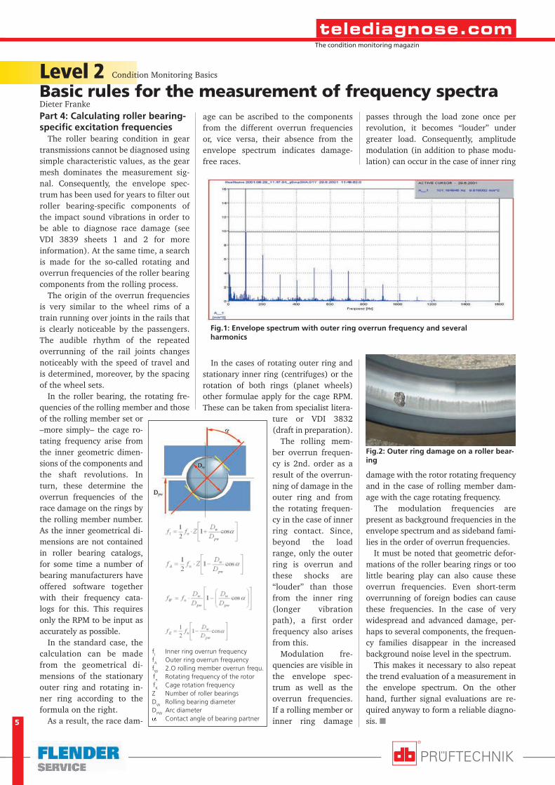
age can be ascribed to the componentsfrom the different overrun frequenciesor, vice versa, their absence from theenvelope spectrum indicates damage-free races.
In the cases of rotating outer ring andstationary inner ring (centrifuges) or therotation of both rings (planet wheels)other formulae apply for the cage RPM.These can be taken from specialist litera-
ture or VDI 3832(draft in preparation).
The rolling mem-ber overrun frequen-cy is 2nd. order as aresult of the overrun-ning of damage in theouter ring and fromthe rotating frequen-cy in the case of innerring contact. Since,beyond the loadrange, only the outerring is overrun andthese shocks are“louder” than thosefrom the inner ring(longer vibrationpath), a first orderfrequency also arisesfrom this.
Modulation fre-quencies are visible inthe envelope spec-trum as well as theoverrun frequencies.If a rolling member orinner ring damage
passes through the load zone once perrevolution, it becomes “louder” undergreater load. Consequently, amplitudemodulation (in addition to phase modu-lation) can occur in the case of inner ring
damage with the rotor rotating frequencyand in the case of rolling member dam-age with the cage rotating frequency.
The modulation frequencies arepresent as background frequencies in theenvelope spectrum and as sideband fami-lies in the order of overrun frequencies.
It must be noted that geometric defor-mations of the roller bearing rings or toolittle bearing play can also cause theseoverrun frequencies. Even short-termoverrunning of foreign bodies can causethese frequencies. In the case of verywidespread and advanced damage, per-haps to several components, the frequen-cy families disappear in the increasedbackground noise level in the spectrum.
This makes it necessary to also repeatthe trend evaluation of a measurement inthe envelope spectrum. On the otherhand, further signal evaluations are re-quired anyway to form a reliable diagno-sis. �
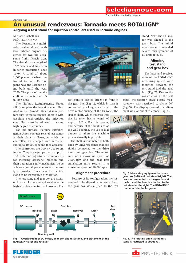
Fig.2: Outer ring damage on a roller bear-ing
Fig.1: Envelope spectrum with outer ring overrun frequency and severalharmonics
Dieter Franke
fI
Inner ring overrun frequencyf
AOuter ring overrun frequency
fW
2.O rolling member overrun frequ.
f
nRotating frequency of the rotor
f
KCage rotation frequency
Z Number of roller bearingsD
WRolling bearing diameter
DPW
Arc diametera Contact angle of bearing partner
6
The condition monitoring magazin
The Tornado is a multi-role combat aircraft withtwo turbofan engines de-signed for two-fold ultra-sonic flight (Mach 2.2).The aircraft has a length of16.7 meters and has beenin series production since1979. A total of about1,000 planes have been de-livered to date. Currentplans have the Tornado be-ing built until the year2020. The price of the air-craft is estimated at 35million Euro.
The Pierburg Luftfahrtgeräte Union(PLU) supplies the injection controllersused in the Tornado. Since it is impor-tant that Tornado engines operate withabsolute synchronicity, the injectioncontrollers must be adjusted to a veryhigh degree of accuracy.
For this purpose, Pierburg Luftfahrt-geräte Union operates several test standsat their plant in Neuss, at which thecontrollers are charged with kerosene,run-up to 10,000 rpm and then adjusted.
The controllers are 100 x 40 x 50 cmin size. They are equipped with approx.100 different adjustment componentsfor metering kerosene injection andtheir operation is fully mechanical. To beable to adjust all parameters as accurate-ly as possible, it is crucial for the teststand to be largely free of vibration.
The test stand and gear box are situat-ed in an explosive atmosphere due to thehighly explosive nature of kerosene. The
Michael Stachelhaus,PRÜFTECHNIK VD
An unusual rendezvous: Tornado meets ROTALIGN®
Aligning a test stand for injection controllers used in Tornado engines
Application
test stand is located directly in front ofthe gear box (Fig. 1), which in turn isconnected by a long spacer shaft to thedrive motor outside of the Ex zone. Thespacer shaft, which reaches intothe Ex zone, has a length ofapprox. 1.2 m. For this reason,and because of the small size ofthe wall opening, the use of dialgauges to align the machineproves virtually impossible.
The shaft is terminated at bothends by universal joints that arerigidly connected to the drivemotor and gear box. The motorruns at a maximum speed of2,500 rpm and the gear boxtranslation ratio results in amaximum speed of 10,000 rpm.
Alignment procedure
Because of its configuration, the sys-tem had to be aligned in two steps. First,the gear box was aligned to the test
stand. Next, the DC mo-tor was aligned to thegear box. The initialmeasurement revealedsevere misalignment ofall units (Fig. 6).
Aligningtest stand
and gear box
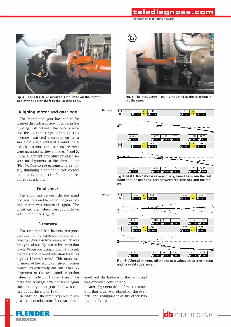
The laser and receiverunits of the ROTALIGN®
measuring system weremounted between thetest stand and the gearbox (Fig. 2). Due to theconstruction at the test
stand, the rotation angle during mea-surement was restricted to about 90°(Fig. 3). The display showed that align-ment was far out of tolerance (Fig. 6).
Fig. 1: Arrangement of DC motor, gear box and test stand, and placement of theROTALIGN® laser and receiver
Fig. 3. The rotating angle at the teststand is restricted to about 90°.
Fig. 2: Measuring equipment betweengear box (left) and test stand (right): Thereceiver is mounted on the gear box atthe left and the laser is attached to thetest stand at the right. The ROTALIGN®
computer is in the forground.
Non-Ex zone
Dividing wall
LaserReceiverLaserReceiver
DC motor Gear box Teststand
7
The condition monitoring magazin
Aligning motor and gear box
The motor and gear box had to bealigned through a narrow opening in thedividing wall between the non-Ex zoneand the Ex zone (Figs. 1 and 5). Thisopening restricted measurement to asmall 75° angle centered around the 6o’clock position. The laser and receiverwere mounted as shown in Figs. 4 and 5.
The alignment procedure revealed se-vere misalignment of the drive motor(Fig. 6). Due to the extremely large off-set, shimming alone could not correctthe misalignment. The foundation re-quired redesigning.
Final check
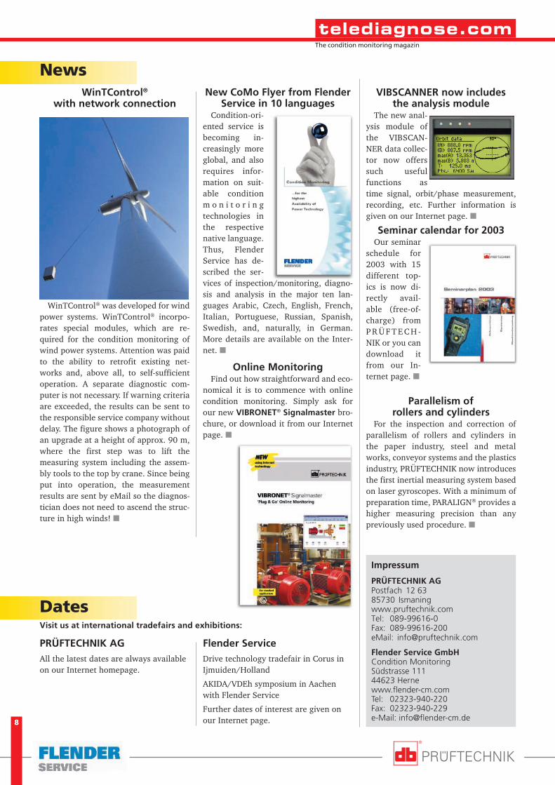
The alignment between the test standand gear box and between the gear boxand motor was measured again. Theoffset and gap values were found to bewithin tolerance (Fig. 7).
Summary
The test stand had become conspicu-ous due to the repeated failure of itsbearings (twice in two years), which wasbrought about by excessive vibrationlevels. When operating under a full load,the test stand showed vibration levels ashigh as 10 mm/s (rms). This made ad-justment of the highly sensitive injectioncontrollers extremely difficult. After re-alignment of the test stand, vibrationvalues fell to below 1 mm/s (rms). Thetest stand bearings have not failed againsince the alignment procedure was car-ried out at the end of 1996.
In addition, the time required to ad-just the Tornado controllers was short-
ened and the lifetime of the test standwas extended considerably.
After alignment of the first test stand,a further order was placed for the over-haul and realignment of the other twotest stands. �
Fig. 15: After alignment, offset and gap values are at a minimumand lie within tolerance.
Fig. 5. The ROTALIGN® laser is mounted at the gear box inthe Ex zone.
Fig. 4: The ROTALIGN® receiver is mounted on the motor-side of the spacer shaft in the Ex-free zone.
Before:
After:
Fig. 6. ROTALIGN® shows severe misalignment between the teststand and the gear box, and between the gear box and the mo-tor.
8
The condition monitoring magazin
Impressum
PRÜFTECHNIK AGPostfach 12 6385730 Ismaningwww.pruftechnik.comTel: 089-99616-0Fax: 089-99616-200eMail: [email protected]
Flender Service GmbHCondition MonitoringSüdstrasse 11144623 Hernewww.flender-cm.comTel: 02323-940-220Fax: 02323-940-229e-Mail: [email protected]
DatesVisit us at international tradefairs and exhibitions:
NewsWinTControl®
with network connection
WinTControl® was developed for windpower systems. WinTControl® incorpo-rates special modules, which are re-quired for the condition monitoring ofwind power systems. Attention was paidto the ability to retrofit existing net-works and, above all, to self-sufficientoperation. A separate diagnostic com-puter is not necessary. If warning criteriaare exceeded, the results can be sent tothe responsible service company withoutdelay. The figure shows a photograph ofan upgrade at a height of approx. 90 m,where the first step was to lift themeasuring system including the assem-bly tools to the top by crane. Since beingput into operation, the measurementresults are sent by eMail so the diagnos-tician does not need to ascend the struc-ture in high winds! �
Flender ServiceDrive technology tradefair in Corus inIjmuiden/Holland
AKIDA/VDEh symposium in Aachenwith Flender Service
Further dates of interest are given onour Internet page.
PRÜFTECHNIK AGAll the latest dates are always availableon our Internet homepage.
Online MonitoringFind out how straightforward and eco-
nomical it is to commence with onlinecondition monitoring. Simply ask forour new VIBRONET® Signalmaster bro-chure, or download it from our Internetpage. �
New CoMo Flyer from FlenderService in 10 languages
Condition-ori-ented service isbecoming in-creasingly moreglobal, and alsorequires infor-mation on suit-able conditionm o n i t o r i n gtechnologies inthe respectivenative language.Thus, FlenderService has de-scribed the ser-vices of inspection/monitoring, diagno-sis and analysis in the major ten lan-guages Arabic, Czech, English, French,Italian, Portuguese, Russian, Spanish,Swedish, and, naturally, in German.More details are available on the Inter-net. �
Seminar calendar for 2003Our seminar
schedule for2003 with 15different top-ics is now di-rectly avail-able (free-of-charge) fromP R Ü F T E C H -NIK or you candownload itfrom our In-ternet page. �
Parallelism ofrollers and cylinders
For the inspection and correction ofparallelism of rollers and cylinders inthe paper industry, steel and metalworks, conveyor systems and the plasticsindustry, PRÜFTECHNIK now introducesthe first inertial measuring system basedon laser gyroscopes. With a minimum ofpreparation time, PARALIGN® provides ahigher measuring precision than anypreviously used procedure. �
VIBSCANNER now includesthe analysis module
The new anal-ysis module ofthe VIBSCAN-NER data collec-tor now offerssuch usefulfunctions astime signal, orbit/phase measurement,recording, etc. Further information isgiven on our Internet page. �