Embed Size (px)
DESCRIPTION
Telecommunication Technologies. Week 9 HDLC (ISO 33009, ISO 4335). HDLC (High level Data Link Control) ISO 33009, ISO 4335. Stations: Primary, Secondary, Combined Link Balance or Unbalanced Transfer Modes NRM, ABM, ARM Frames I-frames, S-frames, U-frames. HDLC Syntax. - PowerPoint PPT Presentation
Citation preview
EIE325: Telecommunication Technologies Maciej Ogorzałek, PolyU, EIE
Telecommunication Technologies
Week 9
HDLC(ISO 33009, ISO 4335)
EIE325: Telecommunication Technologies Maciej Ogorzałek, PolyU, EIE
EIE325: Telecommunication Technologies Maciej Ogorzałek, PolyU, EIE
EIE325: Telecommunication Technologies Maciej Ogorzałek, PolyU, EIE
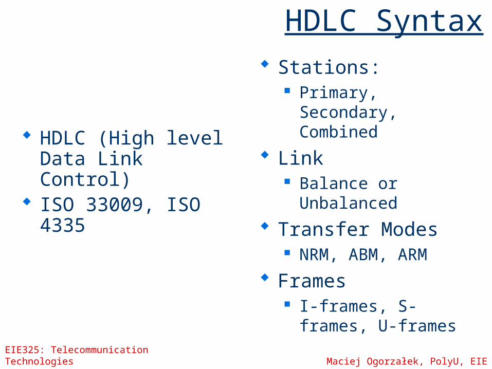
HDLC Syntax
HDLC (High level Data Link Control)
ISO 33009, ISO 4335
Stations: Primary, Secondary,
Combined
Link Balance or
Unbalanced
Transfer Modes NRM, ABM, ARM
Frames I-frames, S-frames,
U-frames
EIE325: Telecommunication Technologies Maciej Ogorzałek, PolyU, EIE
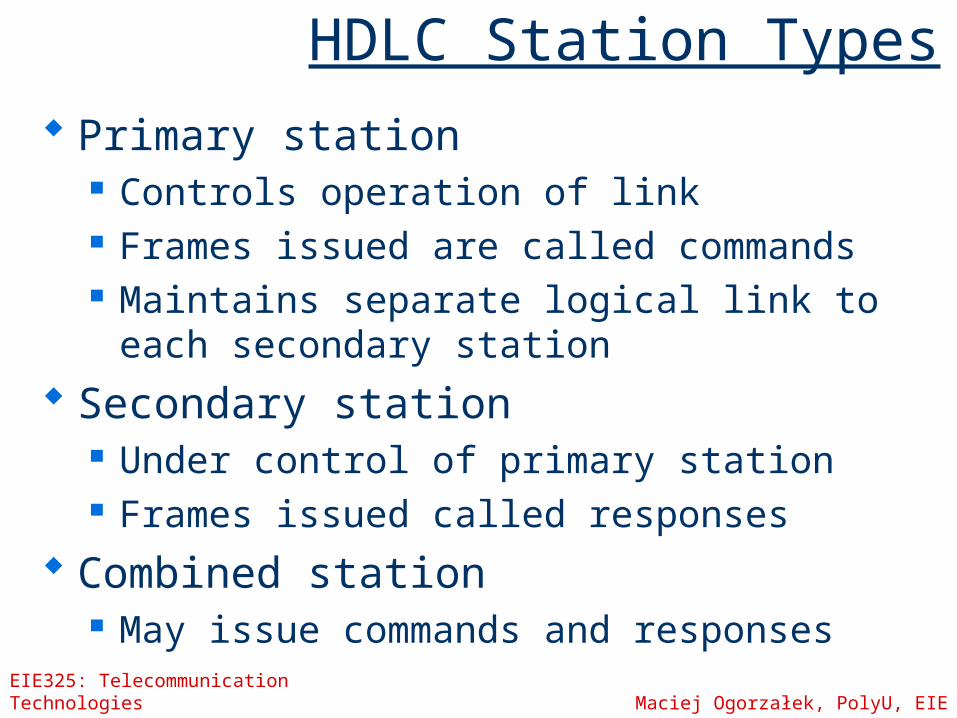
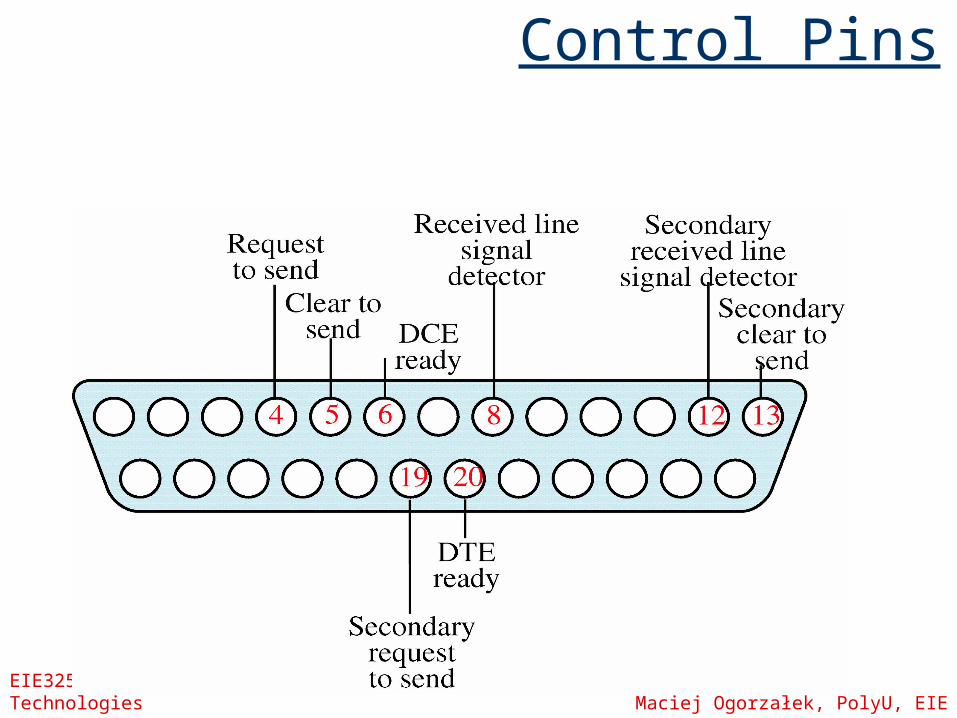
HDLC Station Types Primary station
Controls operation of link Frames issued are called commands Maintains separate logical link to each
secondary station Secondary station
Under control of primary station Frames issued called responses
Combined station May issue commands and responses
EIE325: Telecommunication Technologies Maciej Ogorzałek, PolyU, EIE
HDLC Link Configurations
Unbalanced One primary and one or more secondary
stations Supports full duplex and half duplex
Balanced Two combined stations Supports full duplex and half duplex
EIE325: Telecommunication Technologies Maciej Ogorzałek, PolyU, EIE
HDLC Transfer Modes
Normal Response Mode (NRM) Unbalanced configuration Primary initiates transfer to secondary Secondary may only transmit data in
response to command from primary Used on multi-drop lines Host computer as primary Terminals as secondary
EIE325: Telecommunication Technologies Maciej Ogorzałek, PolyU, EIE
HDLC Transfer Modes
Asynchronous Balanced Mode (ABM) Balanced configuration Either station may initiate transmission
without receiving permission Most widely used No polling overhead
EIE325: Telecommunication Technologies Maciej Ogorzałek, PolyU, EIE
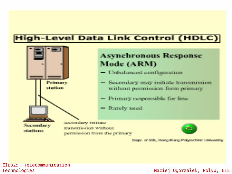
HDLC Transfer Modes
Asynchronous Response Mode (ARM) Unbalanced configuration Secondary may initiate transmission
without permission form primary Primary responsible for line Rarely used
EIE325: Telecommunication Technologies Maciej Ogorzałek, PolyU, EIE
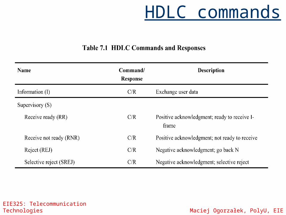
HDLC Frame Types
Three types of frames I-frames : Information (data) S-frames : Supervisory (ARQ) U-frames : Unnumbered (other)
Frame structure the same in each case
EIE325: Telecommunication Technologies Maciej Ogorzałek, PolyU, EIE
Frame Structure
Synchronous transmission All transmissions in frames Single frame format for all data and
control exchanges
EIE325: Telecommunication Technologies Maciej Ogorzałek, PolyU, EIE
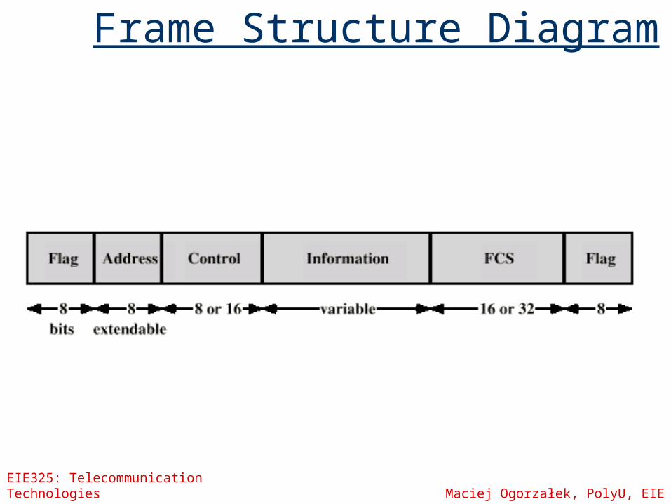
Frame Structure Diagram
EIE325: Telecommunication Technologies Maciej Ogorzałek, PolyU, EIE
Flag Fields
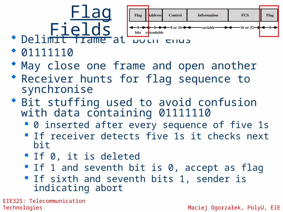
Delimit frame at both ends 01111110 May close one frame and open another Receiver hunts for flag sequence to
synchronise Bit stuffing used to avoid confusion with data
containing 01111110 0 inserted after every sequence of five 1s If receiver detects five 1s it checks next bit If 0, it is deleted If 1 and seventh bit is 0, accept as flag If sixth and seventh bits 1, sender is indicating
abort
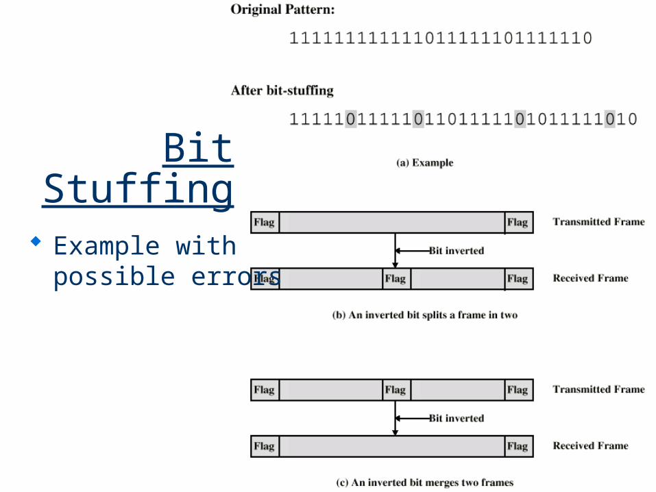
Bit Stuffing
Example with possible errors
EIE325: Telecommunication Technologies Maciej Ogorzałek, PolyU, EIE
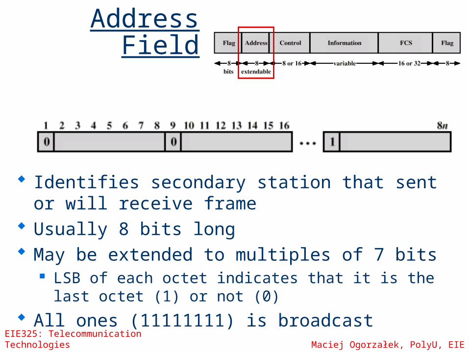
Address Field
Identifies secondary station that sent or will receive frame
Usually 8 bits long May be extended to multiples of 7 bits
LSB of each octet indicates that it is the last octet (1) or not (0)
All ones (11111111) is broadcast
EIE325: Telecommunication Technologies Maciej Ogorzałek, PolyU, EIE
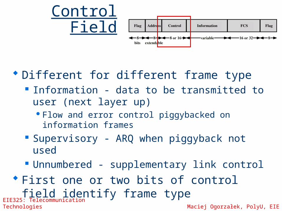
Control Field
Different for different frame type Information - data to be transmitted to user
(next layer up)Flow and error control piggybacked on
information frames Supervisory - ARQ when piggyback not used Unnumbered - supplementary link control
First one or two bits of control field identify frame type
EIE325: Telecommunication Technologies Maciej Ogorzałek, PolyU, EIE
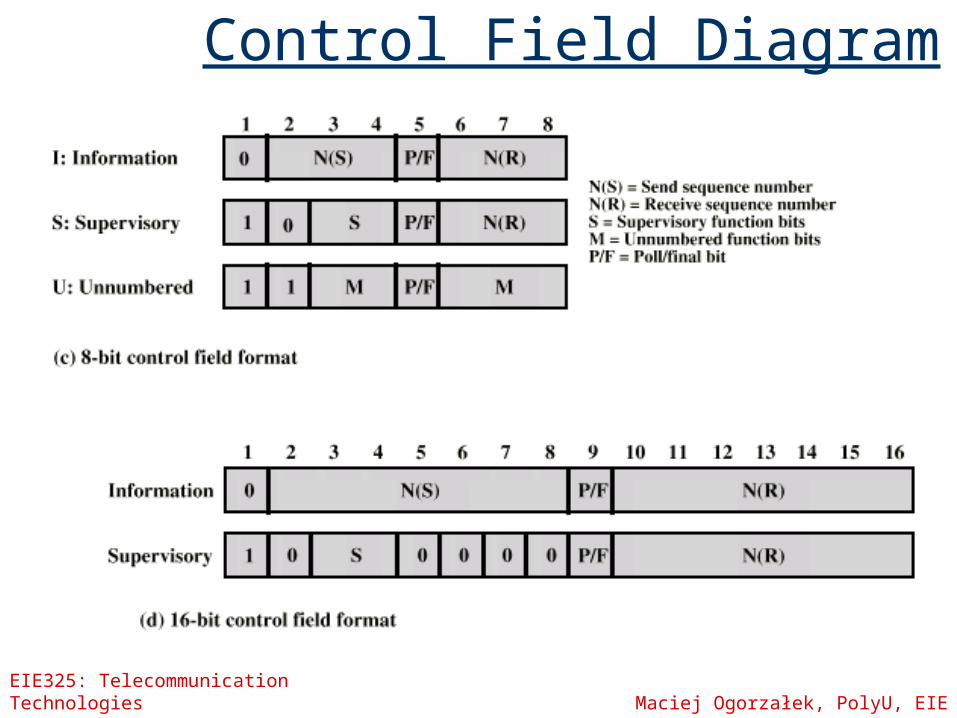
Control Field Diagram
EIE325: Telecommunication Technologies Maciej Ogorzałek, PolyU, EIE
Poll/Final Bit
Use depends on context Command frame
P bit 1 to solicit (poll) response from peer
Response frame F bit 1 indicates response to soliciting command
EIE325: Telecommunication Technologies Maciej Ogorzałek, PolyU, EIE
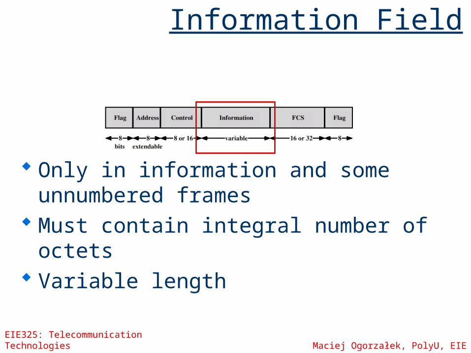
Information Field
Only in information and some unnumbered frames
Must contain integral number of octets Variable length
EIE325: Telecommunication Technologies Maciej Ogorzałek, PolyU, EIE
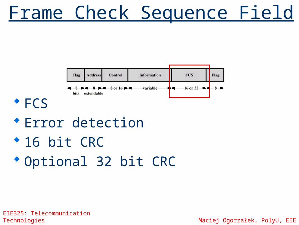
Frame Check Sequence Field
FCS Error detection 16 bit CRC Optional 32 bit CRC
EIE325: Telecommunication Technologies Maciej Ogorzałek, PolyU, EIE
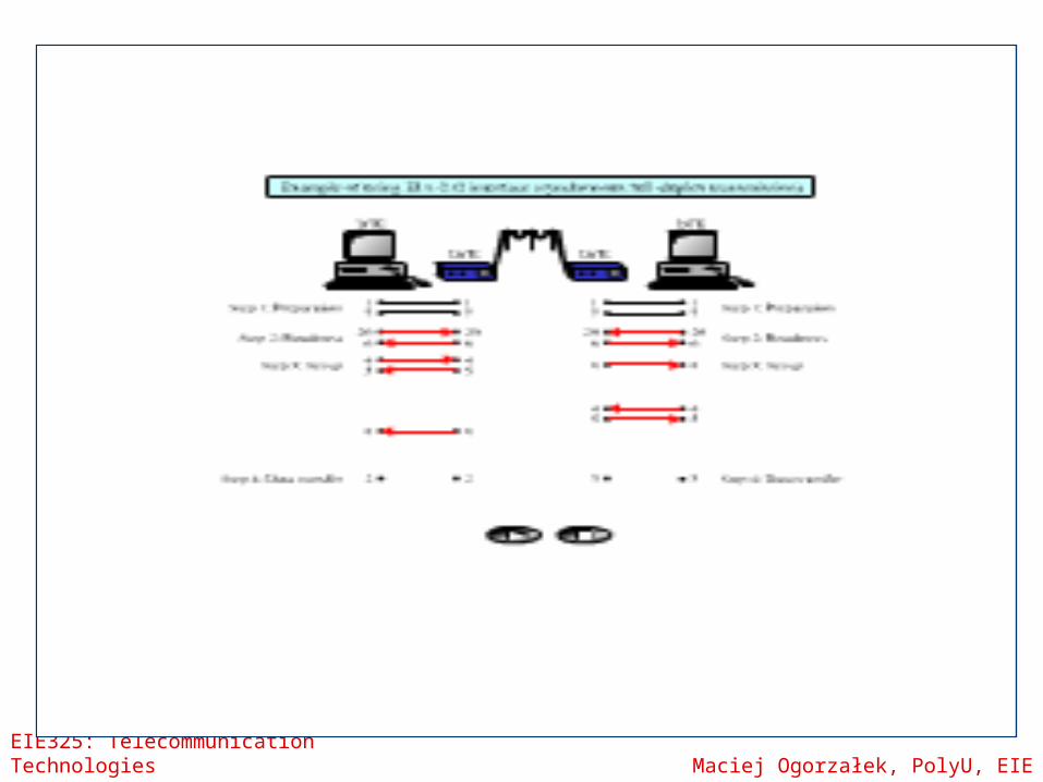
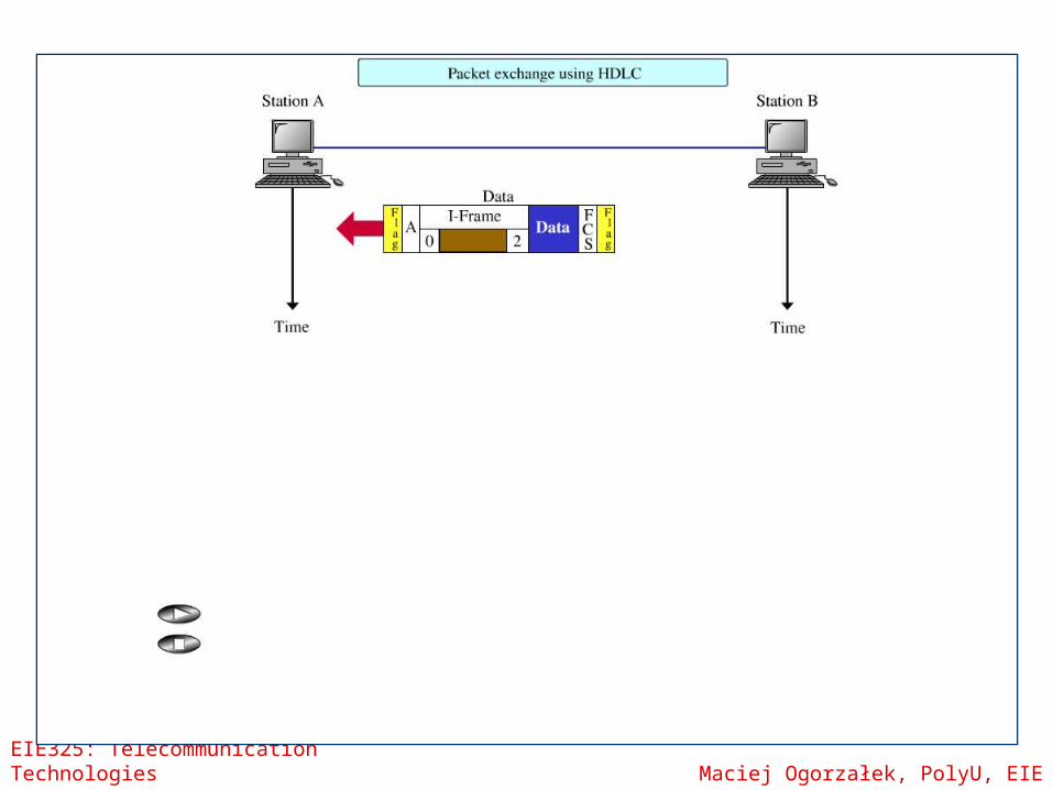
HDLC Operation
Exchange of information, supervisory and unnumbered frames
Three phases Initialisation Data transfer Disconnect
EIE325: Telecommunication Technologies Maciej Ogorzałek, PolyU, EIE
EIE325: Telecommunication Technologies Maciej Ogorzałek, PolyU, EIE
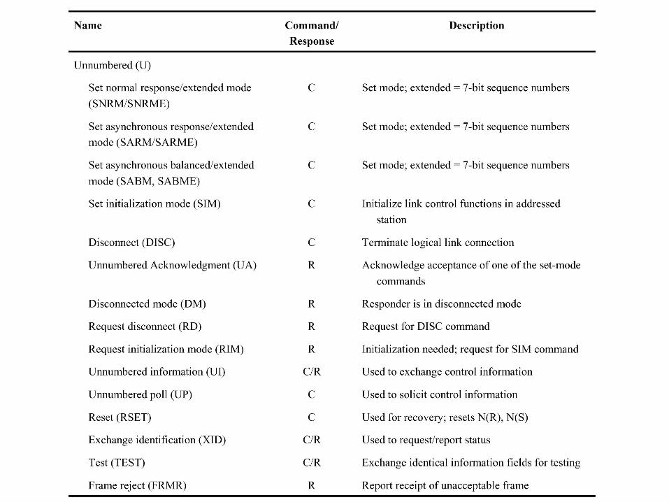
HDLC commands
EIE325: Telecommunication Technologies Maciej Ogorzałek, PolyU, EIE
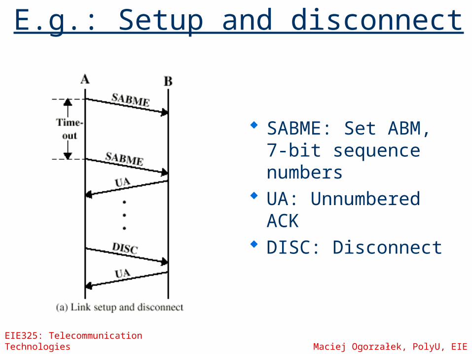
E.g.: Setup and disconnect
SABME: Set ABM, 7-bit sequence numbers
UA: Unnumbered ACK
DISC: Disconnect
EIE325: Telecommunication Technologies Maciej Ogorzałek, PolyU, EIE
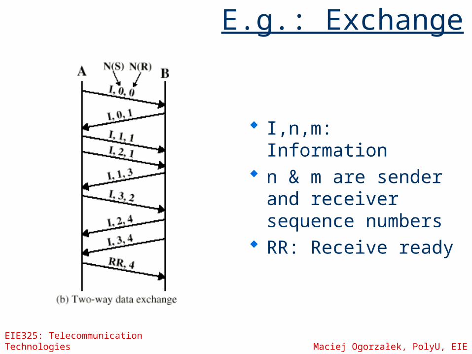
E.g.: Exchange
I,n,m: Information n & m are sender
and receiver sequence numbers
RR: Receive ready
EIE325: Telecommunication Technologies Maciej Ogorzałek, PolyU, EIE
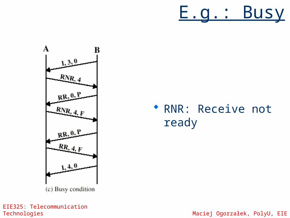
E.g.: Busy
RNR: Receive not ready
EIE325: Telecommunication Technologies Maciej Ogorzałek, PolyU, EIE
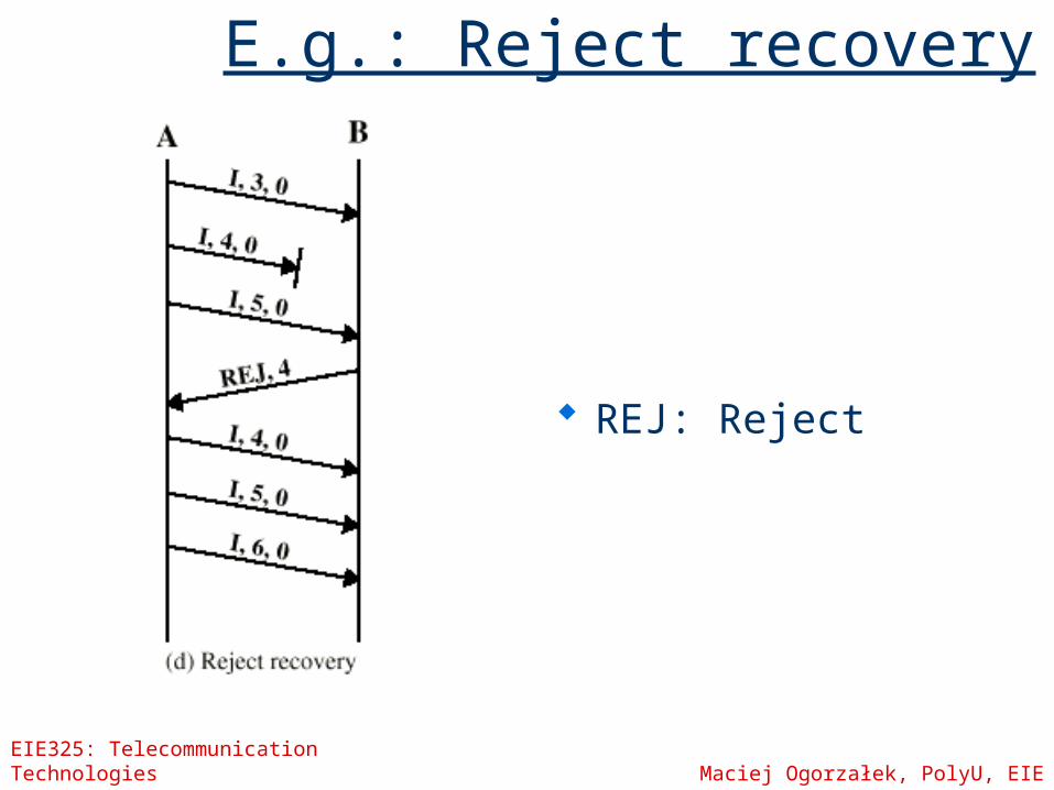
E.g.: Reject recovery
REJ: Reject
EIE325: Telecommunication Technologies Maciej Ogorzałek, PolyU, EIE
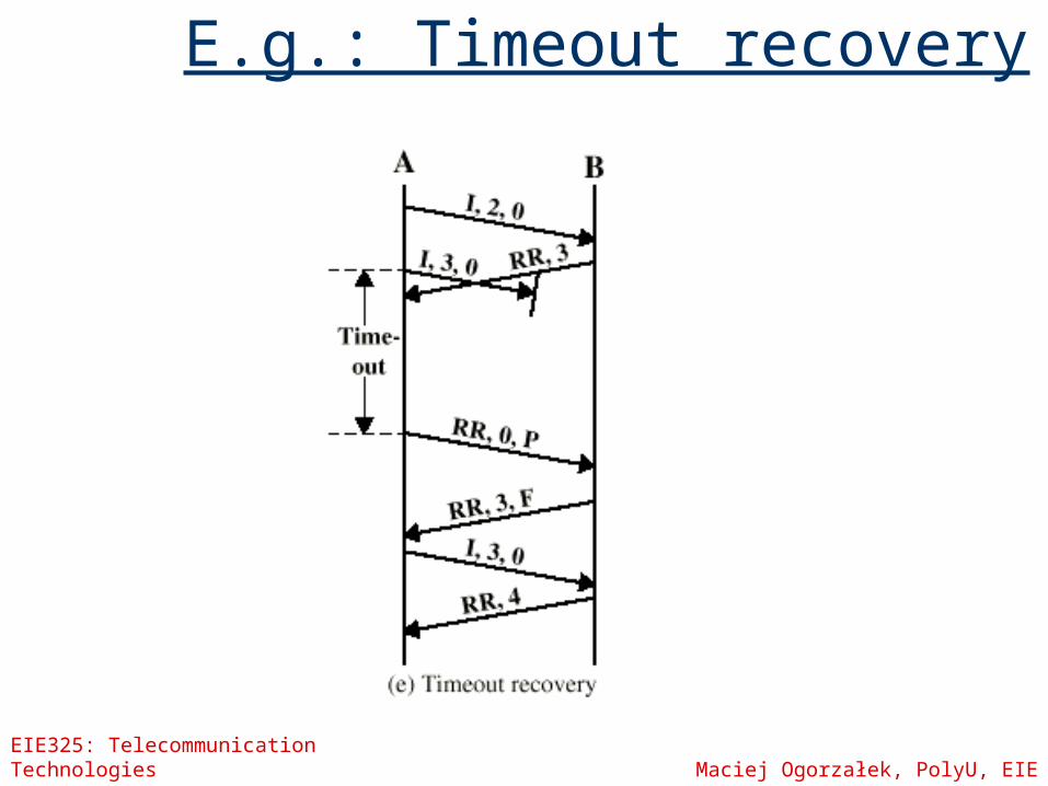
E.g.: Timeout recovery
EIE325: Telecommunication Technologies Maciej Ogorzałek, PolyU, EIE
Telecommunication Technologies
Week 9
Synchronisation
EIE325: Telecommunication Technologies Maciej Ogorzałek, PolyU, EIE
Asynchronous and Synchronous Transmission
Timing problems require a mechanism to synchronise the transmitter and receiver data rate bit duration inter-frame spacing
Two solutions Asynchronous (data not contiguous) Synchronous (data blocks contiguous)
EIE325: Telecommunication Technologies Maciej Ogorzałek, PolyU, EIE
Presumptions
Serial, not Parallel Transmission One bit per signal element Sender and receiver’s clocks are
different Errors in timing (sampling) as well as
amplitude (quantisation)
EIE325: Telecommunication Technologies Maciej Ogorzałek, PolyU, EIE
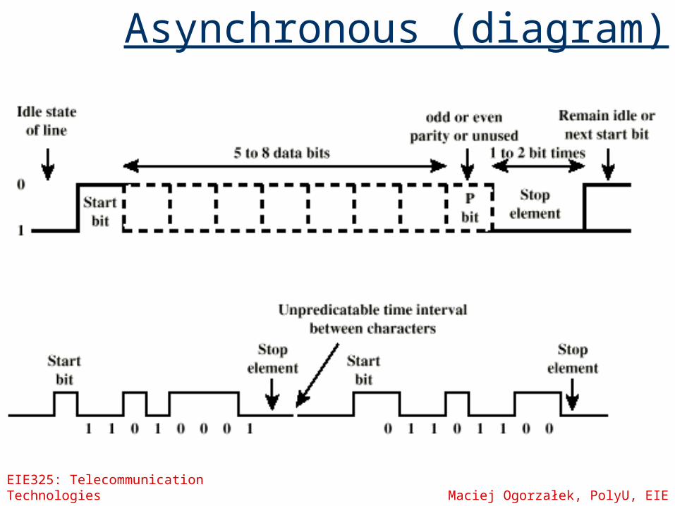
Asynchronous
Data transmitted one character (5-8 bits) at a time
Timing only needs maintaining within each character
Resynchronise for each character Idle (binary 1) between characters Start bit is a binary 0
EIE325: Telecommunication Technologies Maciej Ogorzałek, PolyU, EIE
Asynchronous (diagram)
EIE325: Telecommunication Technologies Maciej Ogorzałek, PolyU, EIE
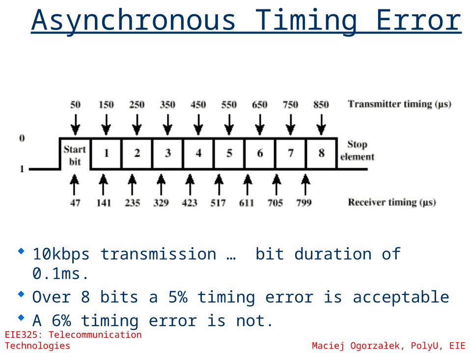
Asynchronous Timing Error
10kbps transmission … bit duration of 0.1ms.
Over 8 bits a 5% timing error is acceptable A 6% timing error is not.
EIE325: Telecommunication Technologies Maciej Ogorzałek, PolyU, EIE
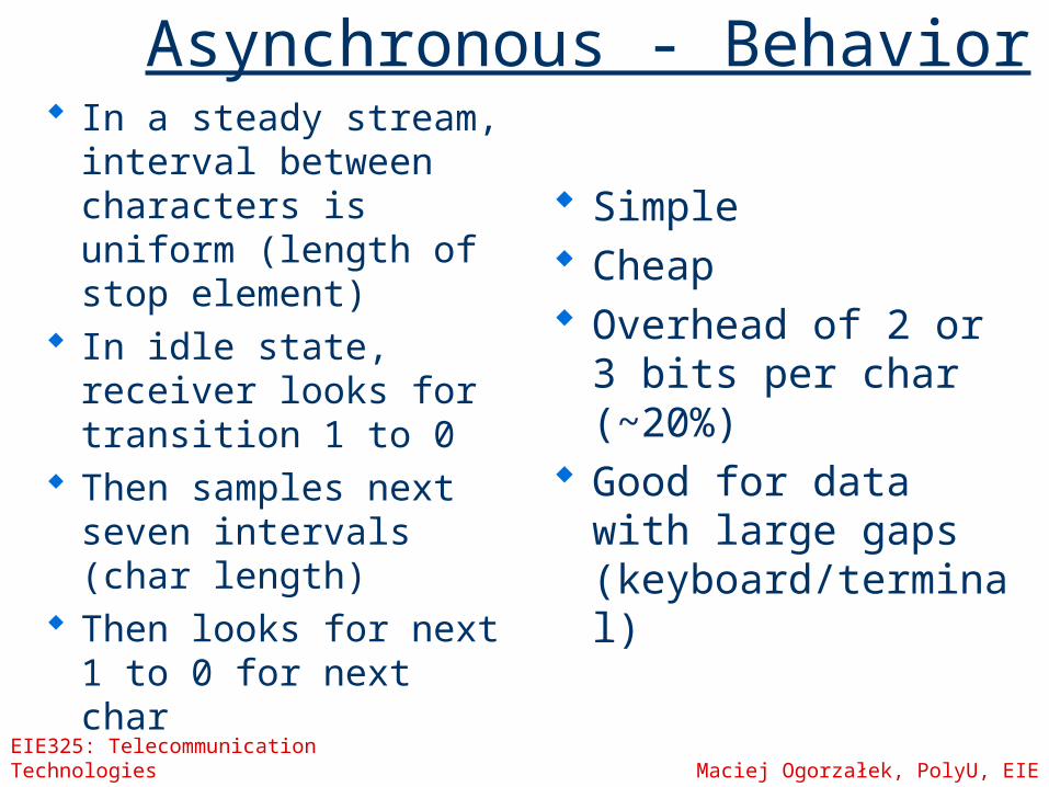
Asynchronous - Behavior In a steady stream,
interval between characters is uniform (length of stop element)
In idle state, receiver looks for transition 1 to 0
Then samples next seven intervals (char length)
Then looks for next 1 to 0 for next char
Simple Cheap Overhead of 2 or 3
bits per char (~20%) Good for data with
large gaps (keyboard/terminal)
EIE325: Telecommunication Technologies Maciej Ogorzałek, PolyU, EIE
Asynchronous Errors
Timing errors extreme discrepancy between sender and
receiver’s clocks. Framing errors
Erroneous start bits
EIE325: Telecommunication Technologies Maciej Ogorzałek, PolyU, EIE
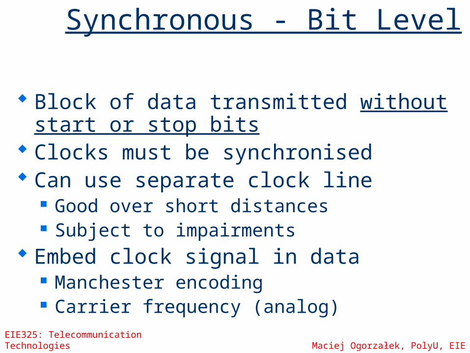
Synchronous - Bit Level
Block of data transmitted without start or stop bits
Clocks must be synchronised Can use separate clock line
Good over short distances Subject to impairments
Embed clock signal in data Manchester encoding Carrier frequency (analog)
EIE325: Telecommunication Technologies Maciej Ogorzałek, PolyU, EIE
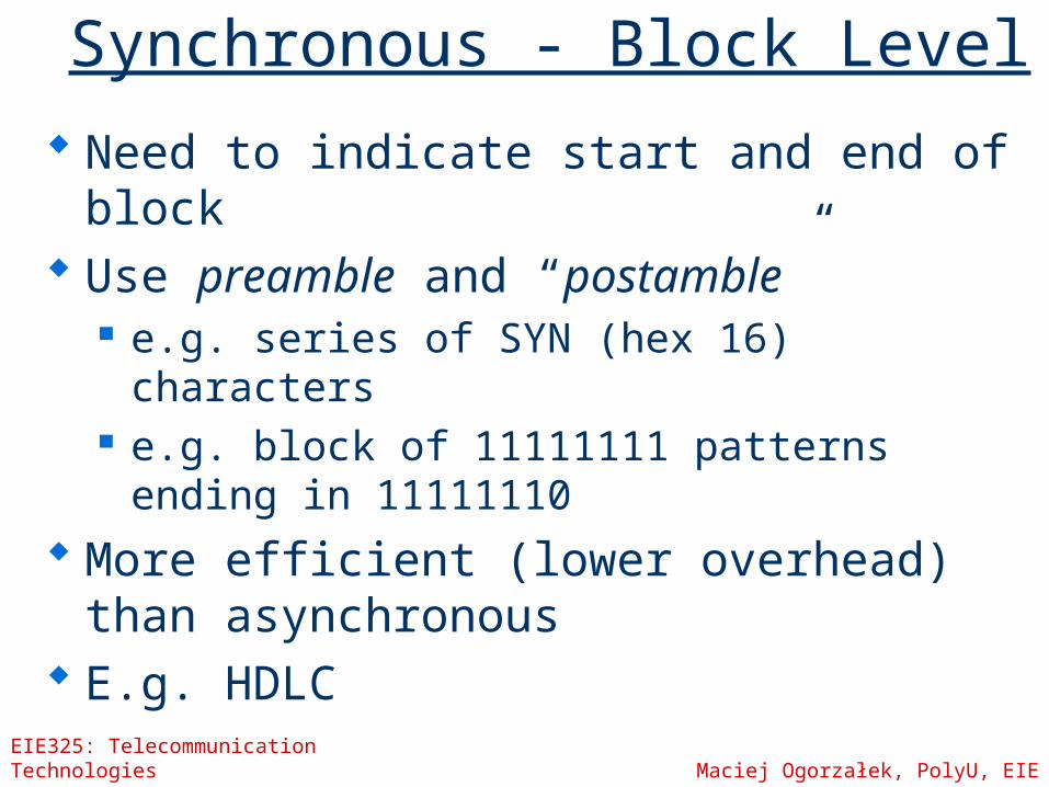
Synchronous - Block Level
Need to indicate start and end of block Use preamble and “postamble”
e.g. series of SYN (hex 16) characters e.g. block of 11111111 patterns ending in
11111110 More efficient (lower overhead) than
asynchronous E.g. HDLC
EIE325: Telecommunication Technologies Maciej Ogorzałek, PolyU, EIE
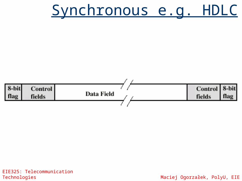
Synchronous e.g. HDLC
EIE325: Telecommunication Technologies Maciej Ogorzałek, PolyU, EIE
Echo Cancellation
Transceiver: Transmitter/Receiver Two parties transmit on the same data
path simultaneously Each is aware of their own transmission
and can subtract that from the resultant to receive the other!
EIE325: Telecommunication Technologies Maciej Ogorzałek, PolyU, EIE
Telecommunication Technologies
Week 9
Interfacing
EIE325: Telecommunication Technologies Maciej Ogorzałek, PolyU, EIE
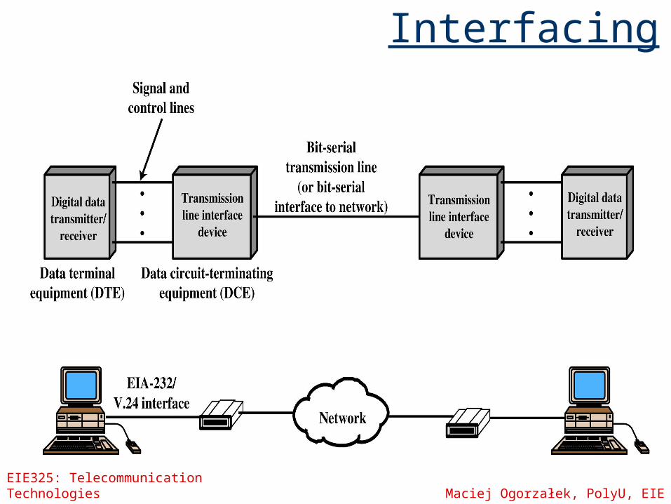
Interfacing Data processing devices (or data
terminal equipment, DTE) do not (usually) include data transmission facilities
Need an interface called data circuit terminating equipment (DCE) e.g. modem, NIC
DCE transmits bits on medium DCE communicates data and control
info with DTE Done over interchange circuits Clear interface standards required
EIE325: Telecommunication Technologies Maciej Ogorzałek, PolyU, EIE
Interfacing
EIE325: Telecommunication Technologies Maciej Ogorzałek, PolyU, EIE
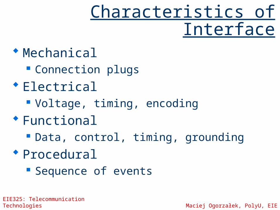
Characteristics of Interface
Mechanical Connection plugs
Electrical Voltage, timing, encoding
Functional Data, control, timing, grounding
Procedural Sequence of events
EIE325: Telecommunication Technologies Maciej Ogorzałek, PolyU, EIE
Two examples
Modem ISDN
EIE325: Telecommunication Technologies Maciej Ogorzałek, PolyU, EIE
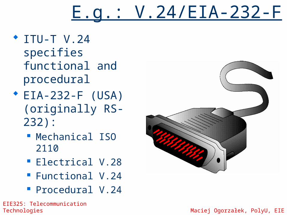
E.g.: V.24/EIA-232-F
ITU-T V.24 specifies functional and procedural
EIA-232-F (USA) (originally RS-232): Mechanical ISO 2110 Electrical V.28 Functional V.24 Procedural V.24
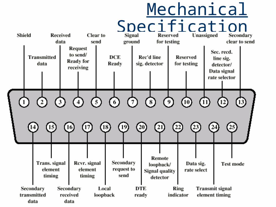
Mechanical Specification
EIE325: Telecommunication Technologies Maciej Ogorzałek, PolyU, EIE
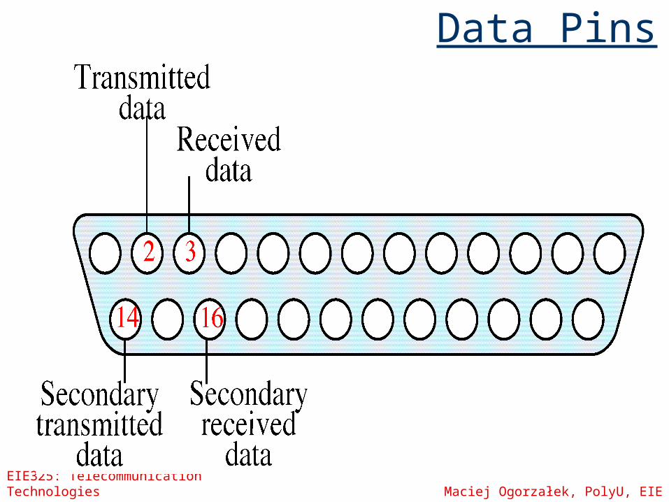
Data Pins
EIE325: Telecommunication Technologies Maciej Ogorzałek, PolyU, EIE
Control Pins
EIE325: Telecommunication Technologies Maciej Ogorzałek, PolyU, EIE
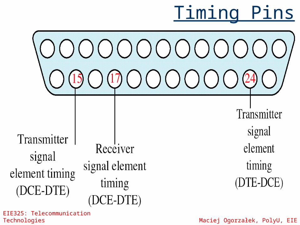
Timing Pins
EIE325: Telecommunication Technologies Maciej Ogorzałek, PolyU, EIE
Electrical Specification
Signaling specification Values interpreted as data or control,
depending on circuit More than -3v is binary 1, more than
+3v is binary 0 (NRZ-L) Signal rate < 20kbps Distance <15m For control, more than-3v is off, +3v is
on
EIE325: Telecommunication Technologies Maciej Ogorzałek, PolyU, EIE
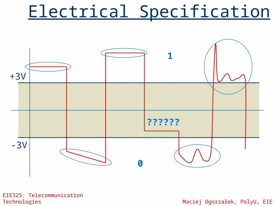
Electrical Specification
0
1
??????
+3V
-3V