Embed Size (px)
Citation preview
PolySwitchResetta
bleDevices–Telecommunications&NetworkingDevices
213
12
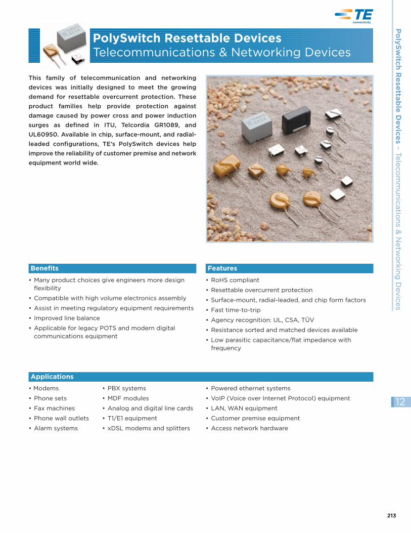
This family of telecommunication and networking
devices was initially designed to meet the growing
demand for resettable overcurrent protection. These
product families help provide protection against
damage caused by power cross and power induction
surges as defined in ITU, Telcordia GR1089, and
UL60950. Available in chip, surface-mount, and radial-
leaded configurations, TE’s PolySwitch devices help
improve the reliability of customer premise and network
equipment world wide.
• Many product choices give engineers more designflexibility
• Compatible with high volume electronics assembly
• Assist in meeting regulatory equipment requirements
• Improved line balance
• Applicable for legacy POTS and modern digitalcommunications equipment
• RoHS compliant
• Resettable overcurrent protection
• Surface-mount, radial-leaded, and chip form factors
• Fast time-to-trip
• Agency recognition: UL, CSA, TÜV
• Resistance sorted and matched devices available
• Low parasitic capacitance/flat impedance withfrequency
• Modems
• Phone sets
• Fax machines
• Phone wall outlets
• Alarm systems
PolySwitch Resettable DevicesTelecommunications & Networking Devices
Benefits Features
Applications
• PBX systems
• MDF modules
• Analog and digital line cards
• T1/E1 equipment
• xDSL modems and splitters
• Powered ethernet systems
• VoIP (Voice over Internet Protocol) equipment
• LAN, WAN equipment
• Customer premise equipment
• Access network hardware
214 RoHS Compliant, ELV Compliant
12
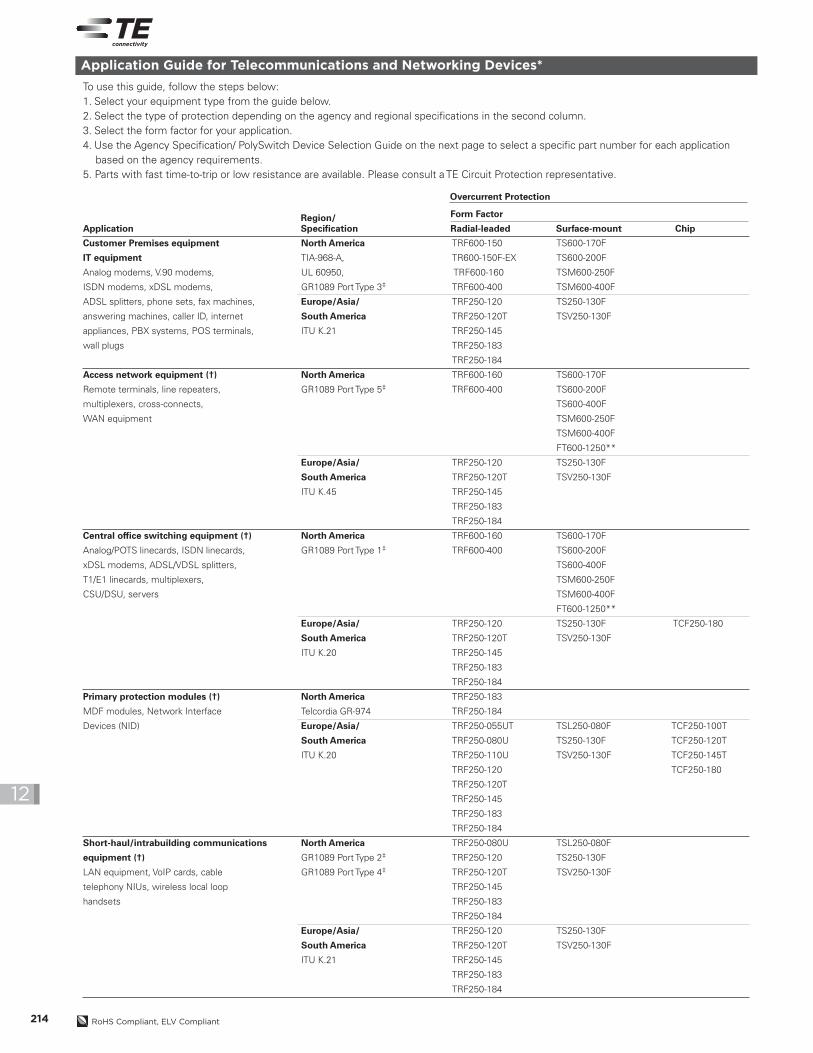
Application Guide for Telecommunications and Networking Devices*
To use this guide, follow the steps below:1. Select your equipment type from the guide below.2. Select the type of protection depending on the agency and regional specifications in the second column.3. Select the form factor for your application.4. Use the Agency Specification/ PolySwitch Device Selection Guide on the next page to select a specific part number for each application
based on the agency requirements.5. Parts with fast time-to-trip or low resistance are available. Please consult a TE Circuit Protection representative.
Customer Premises equipment North America TRF600-150 TS600-170F
IT equipment TIA-968-A, TR600-150F-EX TS600-200F
Analog modems, V.90 modems, UL 60950, TRF600-160 TSM600-250F
ISDN modems, xDSL modems, GR1089 Port Type 3‡ TRF600-400 TSM600-400F
ADSL splitters, phone sets, fax machines, Europe/Asia/ TRF250-120 TS250-130F
answering machines, caller ID, internet South America TRF250-120T TSV250-130F
appliances, PBX systems, POS terminals, ITU K.21 TRF250-145
wall plugs TRF250-183
TRF250-184
Access network equipment (†) North America TRF600-160 TS600-170F
Remote terminals, line repeaters, GR1089 Port Type 5‡ TRF600-400 TS600-200F
multiplexers, cross-connects, TS600-400F
WAN equipment TSM600-250F
TSM600-400F
FT600-1250**
Europe/Asia/ TRF250-120 TS250-130F
South America TRF250-120T TSV250-130F
ITU K.45 TRF250-145
TRF250-183
TRF250-184
Central office switching equipment (†) North America TRF600-160 TS600-170F
Analog/POTS linecards, ISDN linecards, GR1089 Port Type 1‡ TRF600-400 TS600-200F
xDSL modems, ADSL/VDSL splitters, TS600-400F
T1/E1 linecards, multiplexers, TSM600-250F
CSU/DSU, servers TSM600-400F
FT600-1250**
Europe/Asia/ TRF250-120 TS250-130F TCF250-180
South America TRF250-120T TSV250-130F
ITU K.20 TRF250-145
TRF250-183
TRF250-184
Primary protection modules (†) North America TRF250-183
MDF modules, Network Interface Telcordia GR-974 TRF250-184
Devices (NID) Europe/Asia/ TRF250-055UT TSL250-080F TCF250-100T
South America TRF250-080U TS250-130F TCF250-120T
ITU K.20 TRF250-110U TSV250-130F TCF250-145T
TRF250-120 TCF250-180
TRF250-120T
TRF250-145
TRF250-183
TRF250-184
Short-haul/intrabuilding communications North America TRF250-080U TSL250-080F
equipment (†) GR1089 Port Type 2‡ TRF250-120 TS250-130F
LAN equipment, VoIP cards, cable GR1089 Port Type 4‡ TRF250-120T TSV250-130F
telephony NIUs, wireless local loop TRF250-145
handsets TRF250-183
TRF250-184
Europe/Asia/ TRF250-120 TS250-130F
South America TRF250-120T TSV250-130F
ITU K.21 TRF250-145
TRF250-183
TRF250-184
ApplicationRegion/Specification
Form Factor
Radial-leaded Surface-mount Chip
Overcurrent Protection
PolySwitchResetta
bleDevices–Telecommunications&NetworkingDevices
215RoHS Compliant, ELV Compliant
12
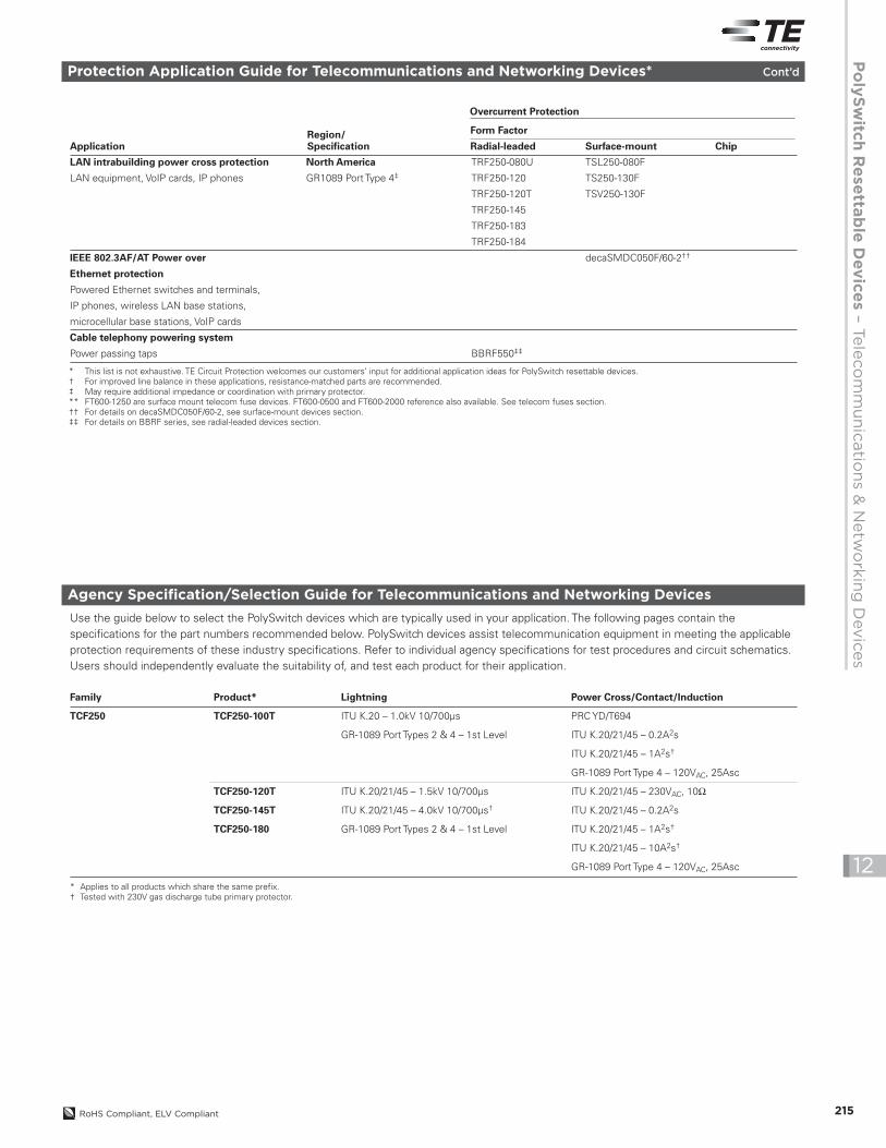
Protection Application Guide for Telecommunications and Networking Devices* Cont’d
LAN intrabuilding power cross protection North America TRF250-080U TSL250-080F
LAN equipment, VoIP cards, IP phones GR1089 Port Type 4‡ TRF250-120 TS250-130F
TRF250-120T TSV250-130F
TRF250-145
TRF250-183
TRF250-184
IEEE 802.3AF/AT Power over decaSMDC050F/60-2††
Ethernet protection
Powered Ethernet switches and terminals,
IP phones, wireless LAN base stations,
microcellular base stations, VoIP cards
Cable telephony powering system
Power passing taps BBRF550‡‡
Agency Specification/Selection Guide for Telecommunications and Networking Devices
Use the guide below to select the PolySwitch devices which are typically used in your application. The following pages contain thespecifications for the part numbers recommended below. PolySwitch devices assist telecommunication equipment in meeting the applicableprotection requirements of these industry specifications. Refer to individual agency specifications for test procedures and circuit schematics.Users should independently evaluate the suitability of, and test each product for their application.
Family Product* Lightning Power Cross/Contact/Induction
TCF250 TCF250-100T ITU K.20 – 1.0kV 10/700µs PRC YD/T694
GR-1089 Port Types 2 & 4 – 1st Level ITU K.20/21/45 – 0.2A2s
ITU K.20/21/45 – 1A2s†
GR-1089 Port Type 4 – 120VAC, 25Asc
TCF250-120T ITU K.20/21/45 – 1.5kV 10/700µs ITU K.20/21/45 – 230VAC, 10Ω
TCF250-145T ITU K.20/21/45 – 4.0kV 10/700µs† ITU K.20/21/45 – 0.2A2s
TCF250-180 GR-1089 Port Types 2 & 4 – 1st Level ITU K.20/21/45 – 1A2s†
ITU K.20/21/45 – 10A2s†
GR-1089 Port Type 4 – 120VAC, 25Asc
* Applies to all products which share the same prefix.† Tested with 230V gas discharge tube primary protector.
ApplicationRegion/Specification
Form Factor
Radial-leaded Surface-mount Chip
Overcurrent Protection
* This list is not exhaustive. TE Circuit Protection welcomes our customers’ input for additional application ideas for PolySwitch resettable devices.† For improved line balance in these applications, resistance-matched parts are recommended.‡ May require additional impedance or coordination with primary protector.** FT600-1250 are surface mount telecom fuse devices. FT600-0500 and FT600-2000 reference also available. See telecom fuses section.†† For details on decaSMDC050F/60-2, see surface-mount devices section.‡‡ For details on BBRF series, see radial-leaded devices section.
216 RoHS Compliant, ELV Compliant
12
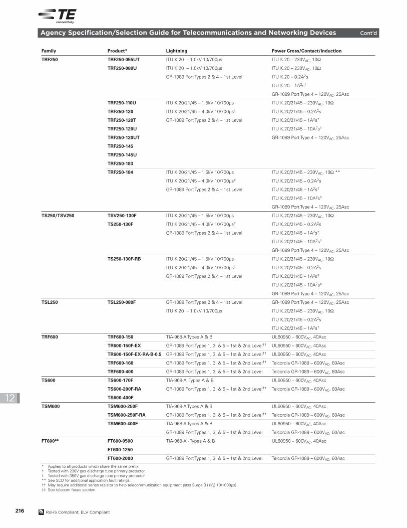
Agency Specification/Selection Guide for Telecommunications and Networking Devices Cont’d
Family Product* Lightning Power Cross/Contact/Induction
TRF250 TRF250-055UT ITU K.20 – 1.0kV 10/700µs ITU K.20 – 230VAC, 10Ω
TRF250-080U ITU K.20 – 1.0kV 10/700µs ITU K.20 – 230VAC, 10Ω
GR-1089 Port Types 2 & 4 – 1st Level ITU K.20 – 0.2A2s
ITU K.20 – 1A2s†
GR-1089 Port Type 4 – 120VAC, 25Asc
TRF250-110U ITU K.20/21/45 – 1.5kV 10/700µs ITU K.20/21/45 – 230VAC, 10Ω
TRF250-120 ITU K.20/21/45 – 4.0kV 10/700µs† ITU K.20/21/45 – 0.2A2s
TRF250-120T GR-1089 Port Types 2 & 4 – 1st Level ITU K.20/21/45 – 1A2s†
TRF250-120U ITU K.20/21/45 – 10A2s†
TRF250-120UT GR-1089 Port Type 4 – 120VAC, 25Asc
TRF250-145
TRF250-145U
TRF250-183
TRF250-184 ITU K.20/21/45 – 1.5kV 10/700µs ITU K.20/21/45 – 230VAC, 10Ω **
ITU K.20/21/45 – 4.0kV 10/700µs‡ ITU K.20/21/45 – 0.2A2s
GR-1089 Port Types 2 & 4 – 1st Level ITU K.20/21/45 – 1A2s‡
ITU K.20/21/45 – 10A2s‡
GR-1089 Port Type 4 – 120VAC, 25Asc
TS250/TSV250 TSV250-130F ITU K.20/21/45 – 1.5kV 10/700µs ITU K.20/21/45 – 230VAC, 10Ω
TS250-130F ITU K.20/21/45 – 4.0kV 10/700µs† ITU K.20/21/45 – 0.2A2s
GR-1089 Port Types 2 & 4 – 1st Level ITU K.20/21/45 – 1A2s†
ITU K.20/21/45 – 10A2s†
GR-1089 Port Type 4 – 120VAC, 25Asc
TS250-130F-RB ITU K.20/21/45 – 1.5kV 10/700µs ITU K.20/21/45 – 230VAC, 10Ω
ITU K.20/21/45 – 4.0kV 10/700µs‡ ITU K.20/21/45 – 0.2A2s
GR-1089 Port Types 2 & 4 – 1st Level ITU K.20/21/45 – 1A2s‡
ITU K.20/21/45 – 10A2s‡
GR-1089 Port Type 4 – 120VAC, 25Asc
TSL250 TSL250-080F GR-1089 Port Types 2 & 4 – 1st Level GR-1089 Port Type 4 – 120VAC, 25Asc
ITU K.20 – 1.0kV 10/700µs ITU K.20/21/45 – 230VAC, 10Ω
ITU K.20/21/45 – 0.2A2s
ITU K.20/21/45 – 1A2s†
TRF600 TRF600-150 TIA-968-A Types A & B UL60950 – 600VAC, 40Asc
TR600-150F-EX GR-1089 Port Types 1, 3, & 5 – 1st & 2nd Level†† UL60950 – 600VAC, 40Asc
TR600-150F-EX-RA-B-0.5 GR-1089 Port Types 1, 3, & 5 – 1st & 2nd Level†† UL60950 – 600VAC, 40Asc
TRF600-160 GR-1089 Port Types 1, 3, & 5 – 1st & 2nd Level†† Telcordia GR-1089 – 600VAC, 60Asc
TRF600-400 GR-1089 Port Types 1, 3, & 5 – 1st & 2nd Level Telcordia GR-1089 – 600VAC, 60Asc
TS600 TS600-170F TIA-968-A Types A & B UL60950 – 600VAC, 40Asc
TS600-200F-RA GR-1089 Port Types 1, 3, & 5 – 1st & 2nd Level†† Telcordia GR-1089 – 600VAC, 60Asc
TS600-400F
TSM600 TSM600-250F TIA-968-A Types A & B UL60950 – 600VAC, 40Asc
TSM600-250F-RA GR-1089 Port Types 1, 3, & 5 – 1st & 2nd Level†† Telcordia GR-1089 – 600VAC, 60Asc
TSM600-400F TIA-968-A Types A & B UL60950 – 600VAC, 40Asc
GR-1089 Port Types 1, 3, & 5 – 1st & 2nd Level Telcordia GR-1089 – 600VAC, 60Asc
FT600‡‡ FT600-0500 TIA-968-A - Types A & B UL60950 – 600VAC, 40Asc
FT600-1250
FT600-2000 GR-1089 Port Types 1, 3, & 5 – 1st & 2nd Level Telcordia GR-1089 – 600VAC, 60Asc
* Applies to all products which share the same prefix.† Tested with 230V gas discharge tube primary protector.‡ Tested with 350V gas discharge tube primary protector.** See SCD for additional application fault ratings.†† May require additional series resistor to help telecommunication equipment pass Surge 3 (1kV, 10/1000µs).‡‡ See telecom fuses section.
PolySwitchResetta
bleDevices–Telecommunications&NetworkingDevices
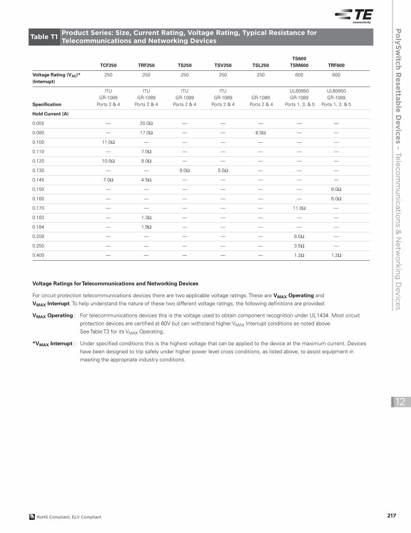
TS600TCF250 TRF250 TS250 TSV250 TSL250 TSM600 TRF600
Voltage Rating (VAC)* 250 250 250 250 250 600 600(Interrupt)
ITU ITU ITU ITU UL60950 UL60950GR-1089 GR-1089 GR-1089 GR-1089 GR-1089 GR-1089 GR-1089
Specification Ports 2 & 4 Ports 2 & 4 Ports 2 & 4 Ports 2 & 4 Ports 2 & 4 Ports 1, 3, & 5 Ports 1, 3, & 5
Hold Current (A)
0.055 — 20.0Ω — — — — —
0.080 — 17.0Ω — — 8.0Ω — —
0.100 11.0Ω — — — — — —
0.110 — 7.0Ω — — — — —
0.120 10.5Ω 8.0Ω — — — — —
0.130 — — 9.0Ω 5.5Ω — — —
0.145 7.0Ω 4.5Ω — — — — —
0.150 — — — — — — 8.0Ω
0.160 — — — — — — 6.0Ω
0.170 — — — — — 11.0Ω —
0.183 — 1.3Ω — — — — —
0.184 — 1.9Ω — — — — —
0.200 — — — — — 8.5Ω —
0.250 — — — — — 3.5Ω —
0.400 — — — — — 1.2Ω 1.2Ω
217RoHS Compliant, ELV Compliant
12
Voltage Ratings forTelecommunications and Networking Devices
For circuit protection telecommunications devices there are two applicable voltage ratings. These are VMAX Operating and
VMAX Interrupt. To help understand the nature of these two different voltage ratings, the following definitions are provided:
VMAX Operating : For telecommunications devices this is the voltage used to obtain component recognition under UL1434. Most circuit
protection devices are certified at 60V but can withstand higher VMAX Interrupt conditions as noted above.
See Table T3 for its VMAX Operating.
*VMAX Interrupt : Under specified conditions this is the highest voltage that can be applied to the device at the maximum current. Devices
have been designed to trip safely under higher power level cross conditions, as listed above, to assist equipment in
meeting the appropriate industry conditions.
Table T1Product Series: Size, Current Rating, Voltage Rating, Typical Resistance forTelecommunications and Networking Devices
218 RoHS Compliant, ELV Compliant
12
%o
fR
ated
Ho
ldan
dTr
ipC
urr
ent
Device’s AmbientTemperature (˚C)
200
150
100
50
0-40 -20 0 20 40 60 80
A
A
B
B
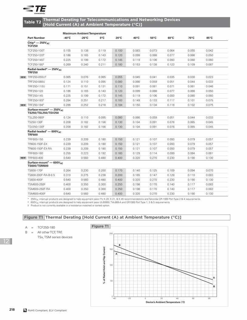
Figure T1A = TCF250-180
B = All other TCF, TRF,
TSx, TSM series devices
NEW
MaximumAmbientTemperature
Part Number -40°C -20°C 0°C 20°C 40°C 50°C 60°C 70°C 85°C
Chip* — 250VACTCF250
TCF250-100T 0.155 0.138 0.119 0.100 0.083 0.073 0.064 0.055 0.042
TCF250-120T 0.186 0.165 0.143 0.120 0.099 0.088 0.077 0.066 0.050
TCF250-145T 0.225 0.199 0.172 0.145 0.119 0.106 0.093 0.080 0.060
TCF250-180‡ 0.269 0.240 0.211 0.180 0.153 0.138 0.123 0.109 0.087
Radial-leaded* — 250VACTRF250
TRF250-055UT 0.085 0.076 0.065 0.055 0.045 0.041 0.035 0.030 0.023
TRF250-080U 0.124 0.110 0.095 0.080 0.066 0.059 0.051 0.044 0.033
TRF250-110U 0.171 0.151 0.131 0.110 0.091 0.081 0.071 0.061 0.046
TRF250-120 0.186 0.165 0.143 0.120 0.099 0.088 0.077 0.066 0.050
TRF250-145 0.225 0.199 0.172 0.145 0.119 0.106 0.093 0.080 0.060
TRF250-183‡ 0.284 0.251 0.217 0.183 0.149 0.133 0.117 0.101 0.075
TRF250-184‡ 0.286 0.252 0.218 0.184 0.150 0.134 0.118 0.102 0.075
Surface-mount* — 250VACTS250/TSL250/TSV250
TSL250-080F 0.124 0.110 0.095 0.080 0.066 0.059 0.051 0.044 0.033
TS250-130F 0.208 0.182 0.156 0.130 0.104 0.091 0.078 0.065 0.045
TSV250-130F 0.208 0.182 0.156 0.130 0.104 0.091 0.078 0.065 0.045
Radial-leaded† — 600VACTRF600
TRF600-150 0.239 0.209 0.180 0.150 0.121 0.107 0.093 0.079 0.057
TR600-150F-EX 0.239 0.209 0.180 0.150 0.121 0.107 0.093 0.079 0.057
TR600-150F-EX-RA 0.239 0.209 0.180 0.150 0.121 0.107 0.093 0.079 0.057
TRF600-160 0.255 0.223 0.192 0.160 0.129 0.114 0.099 0.084 0.061
TRF600-400 0.640 0.560 0.480 0.400 0.320 0.270 0.230 0.190 0.130
Surface-mount† — 600VACTS600/TSM600
TS600-170F 0.264 0.230 0.200 0.170 0.140 0.125 0.109 0.094 0.070
TS600-200F-RA-B-0.5 0.310 0.275 0.238 0.200 0.165 0.147 0.128 0.110 0.083
TS600-400F 0.640 0.560 0.480 0.400 0.320 0.270 0.230 0.190 0.130
TSM600-250F 0.400 0.350 0.300 0.250 0.198 0.170 0.140 0.117 0.083
TSM600-250F-RA 0.400 0.350 0.300 0.250 0.198 0.170 0.140 0.117 0.083
TSM600-400F 0.640 0.560 0.480 0.400 0.320 0.270 0.230 0.190 0.130
* 250VAC interrupt products are designed to help equipment pass ITU K.20, K.21, & K.45 recommendations and Telcordia GR-1089 Port Type 2 & 4 requirements.† 600VAC interrupt products are designed to help equipment pass UL60950, TIA-968-A and GR1089 Port Type 1, 3 & 5 requirements.‡ Product is not currently available in a resistance matched or sorted option.
NEW
NEW
Table T2Thermal Derating for Telecommunications and Networking Devices[Hold Current (A) at Ambient Temperature (°C)]
Figure T1 Thermal Derating [Hold Current (A) at Ambient Temperature (°C)]
PolySwitchResetta
bleDevices–Telecommunications&NetworkingDevices
219RoHS Compliant, ELV Compliant
12
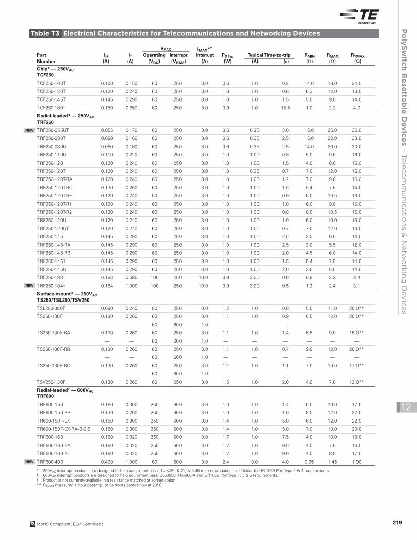
Chip* — 250VACTCF250
TCF250-100T 0.100 0.150 60 250 3.0 0.6 1.0 0.2 14.0 18.0 24.0
TCF250-120T 0.120 0.240 60 250 3.0 1.0 1.0 0.6 6.3 12.0 18.0
TCF250-145T 0.145 0.290 60 250 3.0 1.0 1.0 1.5 5.0 9.0 14.0
TCF250-180‡ 0.180 0.650 60 250 3.0 0.9 1.0 15.5 1.0 2.2 4.0
Radial-leaded* — 250VACTRF250
TRF250-055UT 0.055 0.170 60 250 3.0 0.6 0.28 3.0 15.0 25.0 35.0
TRF250-080T 0.080 0.160 60 250 3.0 0.6 0.35 2.5 15.0 22.0 33.0
TRF250-080U 0.080 0.160 60 250 3.0 0.6 0.35 2.5 14.0 20.0 33.0
TRF250-110U 0.110 0.220 60 250 3.0 1.0 1.00 0.8 5.0 9.0 16.0
TRF250-120 0.120 0.240 60 250 3.0 1.0 1.00 1.5 4.0 8.0 16.0
TRF250-120T 0.120 0.240 60 250 3.0 1.0 0.35 0.7 7.0 12.0 16.0
TRF250-120T-RA 0.120 0.240 60 250 3.0 1.0 1.00 1.2 7.0 9.0 16.0
TRF250-120T-RC 0.130 0.260 60 250 3.0 1.0 1.00 1.5 5.4 7.5 14.0
TRF250-120T-RF 0.120 0.240 60 250 3.0 1.0 1.00 0.9 6.0 10.5 16.0
TRF250-120T-R1 0.120 0.240 60 250 3.0 1.0 1.00 1.0 6.0 9.0 16.0
TRF250-120T-R2 0.120 0.240 60 250 3.0 1.0 1.00 0.8 8.0 10.5 16.0
TRF250-120U 0.120 0.240 60 250 3.0 1.0 1.00 1.0 6.0 10.0 16.0
TRF250-120UT 0.120 0.240 60 250 3.0 1.0 1.00 0.7 7.0 12.0 16.0
TRF250-145 0.145 0.290 60 250 3.0 1.0 1.00 2.5 3.0 6.0 14.0
TRF250-145-RA 0.145 0.290 60 250 3.0 1.0 1.00 2.5 3.0 5.5 12.0
TRF250-145-RB 0.145 0.290 60 250 3.0 1.0 1.00 2.0 4.5 6.0 14.0
TRF250-145T 0.145 0.290 60 250 3.0 1.0 1.00 1.5 5.4 7.5 14.0
TRF250-145U 0.145 0.290 60 250 3.0 1.0 1.00 2.0 3.5 6.5 14.0
TRF250-183‡ 0.183 0.685 100 250 10.0 0.9 3.00 0.6 0.8 2.2 3.4
TRF250-184‡ 0.184 1.000 100 250 10.0 0.9 3.00 0.5 1.2 2.4 3.1
Surface-mount* — 250VACTS250/TSL250/TSV250
TSL250-080F 0.080 0.240 80 250 3.0 1.2 1.0 0.8 5.0 11.0 20.0**
TS250-130F 0.130 0.260 60 250 3.0 1.1 1.0 0.9 6.5 12.0 20.0**
— — 60 600 1.0 — — — — — —
TS250-130F-RA 0.130 0.260 60 250 3.0 1.1 1.0 1.4 6.5 9.0 15.0**
— — 60 600 1.0 — — — — — —
TS250-130F-RB 0.130 0.260 60 250 3.0 1.1 1.0 0.7 9.0 12.0 20.0**
— — 60 600 1.0 — — — — — —
TS250-130F-RC 0.130 0.260 60 250 3.0 1.1 1.0 1.1 7.0 10.0 17.0**
— — 60 600 1.0 — — — — — —
TSV250-130F 0.130 0.260 60 250 3.0 1.5 1.0 2.0 4.0 7.0 12.0**
Radial-leaded† — 600VACTRF600
TRF600-150 0.150 0.300 250 600 3.0 1.0 1.0 1.4 6.0 10.0 17.0
TRF600-150-RB 0.130 0.260 250 600 3.0 1.0 1.0 1.0 9.0 12.0 22.0
TR600-150F-EX 0.150 0.300 250 600 3.0 1.4 1.0 5.0 6.0 12.0 22.0
TR600-150F-EX-RA-B-0.5 0.150 0.300 250 600 3.0 1.4 1.0 5.0 7.0 10.0 20.0
TRF600-160 0.160 0.320 250 600 3.0 1.7 1.0 7.5 4.0 10.0 18.0
TRF600-160-RA 0.160 0.320 250 600 3.0 1.7 1.0 9.5 4.0 7.0 16.0
TRF600-160-R1 0.160 0.320 250 600 3.0 1.7 1.0 9.0 4.0 8.0 17.0
TRF600-400 0.400 1.000 60 600 3.0 2.4 3.0 4.0 0.95 1.45 1.90
PartNumber
IH(A)
IT(A)
PDTyp(W)
TypicalTime-to-trip(A) (s)
RMIN(Ω)
R1MAX(Ω)
RMAX(Ω)
Operating(VDC)
Interrupt(VRMS)
IMAX*†
Interrupt(A)
VMAX
NEW
NEW
* 250VAC interrupt products are designed to help equipment pass ITU K.20, K.21, & K.45 recommendations and Telcordia GR-1089 Port Type 2 & 4 requirements.† 600VAC interrupt products are designed to help equipment pass UL60950, TIA-968-A and GR1089 Port Type 1, 3 & 5 requirements.‡ Product is not currently available in a resistance matched or sorted option.** R1MAX measured 1 hour post-trip, or 24 hours post-reflow at 20°C.
NEW
Table T3 Electrical Characteristics for Telecommunications and Networking Devices
220 RoHS Compliant, ELV Compliant
12
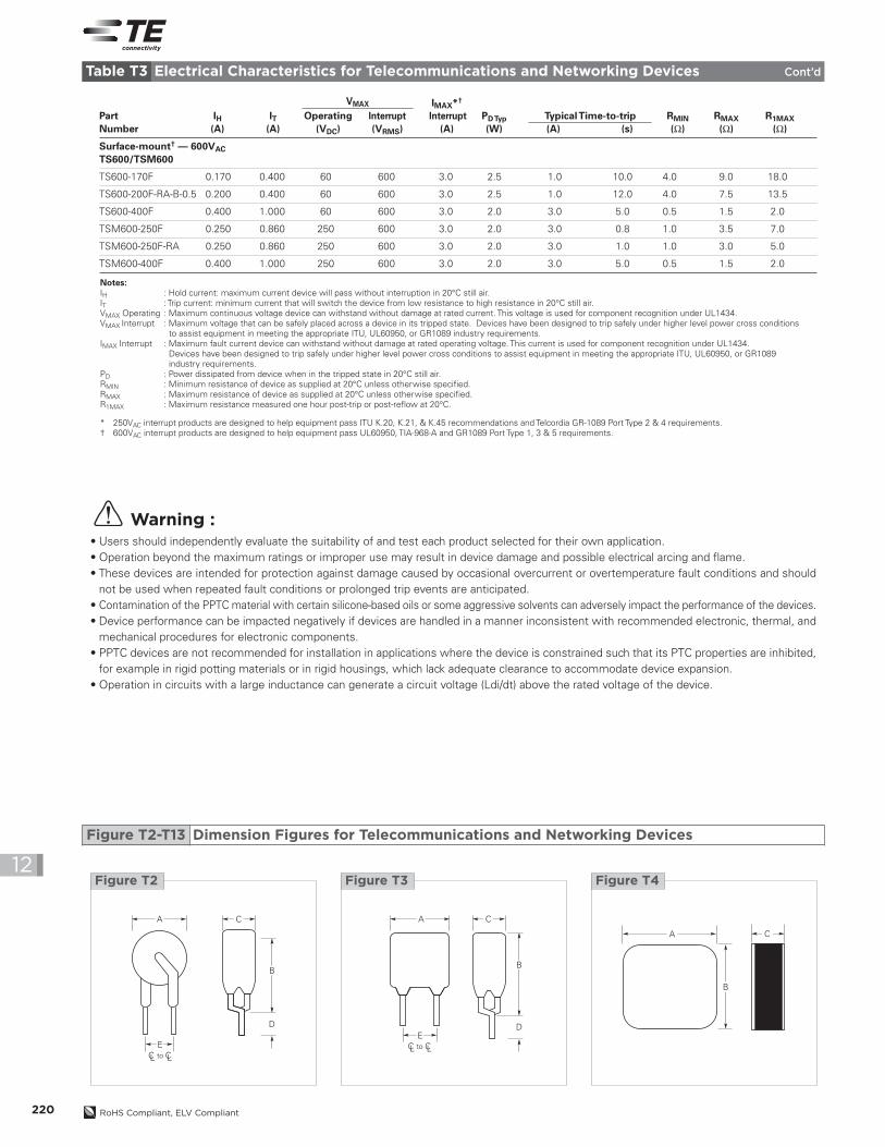
Notes:IH : Hold current: maximum current device will pass without interruption in 20°C still air.IT : Trip current: minimum current that will switch the device from low resistance to high resistance in 20°C still air.VMAX Operating : Maximum continuous voltage device can withstand without damage at rated current. This voltage is used for component recognition under UL1434.VMAX Interrupt : Maximum voltage that can be safely placed across a device in its tripped state. Devices have been designed to trip safely under higher level power cross conditions
to assist equipment in meeting the appropriate ITU, UL60950, or GR1089 industry requirements.IMAX Interrupt : Maximum fault current device can withstand without damage at rated operating voltage. This current is used for component recognition under UL1434.
Devices have been designed to trip safely under higher level power cross conditions to assist equipment in meeting the appropriate ITU, UL60950, or GR1089industry requirements.
PD : Power dissipated from device when in the tripped state in 20°C still air.RMIN : Minimum resistance of device as supplied at 20°C unless otherwise specified.RMAX : Maximum resistance of device as supplied at 20°C unless otherwise specified.R1MAX : Maximum resistance measured one hour post-trip or post-reflow at 20°C.
* 250VAC interrupt products are designed to help equipment pass ITU K.20, K.21, & K.45 recommendations and Telcordia GR-1089 Port Type 2 & 4 requirements.† 600VAC interrupt products are designed to help equipment pass UL60950, TIA-968-A and GR1089 Port Type 1, 3 & 5 requirements.
Surface-mount† — 600VACTS600/TSM600
TS600-170F 0.170 0.400 60 600 3.0 2.5 1.0 10.0 4.0 9.0 18.0
TS600-200F-RA-B-0.5 0.200 0.400 60 600 3.0 2.5 1.0 12.0 4.0 7.5 13.5
TS600-400F 0.400 1.000 60 600 3.0 2.0 3.0 5.0 0.5 1.5 2.0
TSM600-250F 0.250 0.860 250 600 3.0 2.0 3.0 0.8 1.0 3.5 7.0
TSM600-250F-RA 0.250 0.860 250 600 3.0 2.0 3.0 1.0 1.0 3.0 5.0
TSM600-400F 0.400 1.000 250 600 3.0 2.0 3.0 5.0 0.5 1.5 2.0
PartNumber
IH(A)
IT(A)
PDTyp(W)
TypicalTime-to-trip(A) (s)
RMIN(Ω)
R1MAX(Ω)
RMAX(Ω)
Operating(VDC)
Interrupt(VRMS)
IMAX*†
Interrupt(A)
VMAX
Warning :• Users should independently evaluate the suitability of and test each product selected for their own application.• Operation beyond the maximum ratings or improper use may result in device damage and possible electrical arcing and flame.• These devices are intended for protection against damage caused by occasional overcurrent or overtemperature fault conditions and should
not be used when repeated fault conditions or prolonged trip events are anticipated.• Contamination of the PPTC material with certain silicone-based oils or some aggressive solvents can adversely impact the performance of the devices.• Device performance can be impacted negatively if devices are handled in a manner inconsistent with recommended electronic, thermal, and
mechanical procedures for electronic components.• PPTC devices are not recommended for installation in applications where the device is constrained such that its PTC properties are inhibited,
for example in rigid potting materials or in rigid housings, which lack adequate clearance to accommodate device expansion.• Operation in circuits with a large inductance can generate a circuit voltage (Ldi/dt) above the rated voltage of the device.
C
B
D
A
EC toL CL
Figure T2
C
B
D
A
EC toL CL
Figure T3
B
A C
Figure T4
Table T3 Electrical Characteristics for Telecommunications and Networking Devices Cont’d
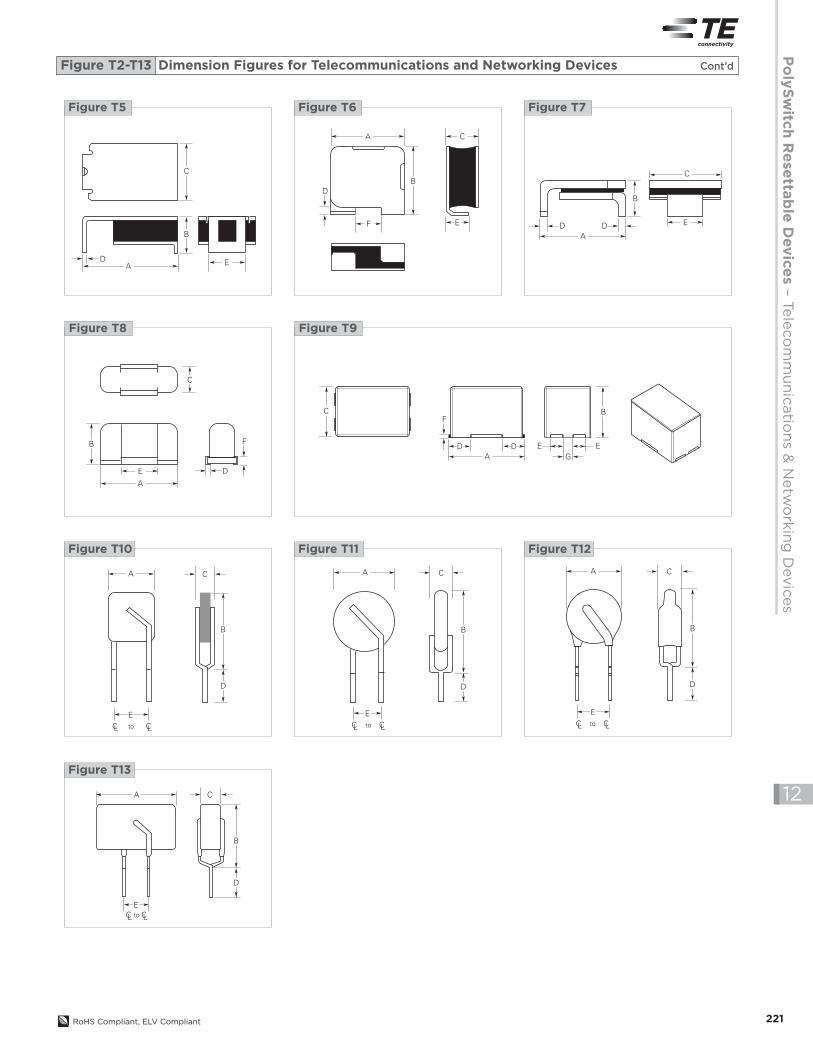
Figure T2-T13 Dimension Figures for Telecommunications and Networking Devices
PolySwitchResetta
bleDevices–Telecommunications&NetworkingDevices
221RoHS Compliant, ELV Compliant
12
C B
EG
EA
D D
F
Figure T9
C
B
D EA
Figure T5
BD
F
A C
E
Figure T6
B
C
E
AD D
Figure T7
C
B
E D
F
A
Figure T8
D
B
A C
EC toL CL
Figure T10
D
B
A C
EC toL CL
Figure T11
D
B
CA
EC toL CL
Figure T13
A C
EC toL CL
D
B
Figure T12
Figure T2-T13 Dimension Figures for Telecommunications and Networking Devices Cont’d

222 RoHS Compliant, ELV Compliant
12
TCF250V*
TCF250-100T 4.6 4.9 4.6 4.9 2.0 2.3 — — — — — — — — T4 0.24
(0.18) (0.19) (0.18) (0.19) (0.08) (0.09)
TCF250-120T 5.4 5.6 5.4 5.6 2.0 2.3 — — — — — — — — T4 0.28
(0.21) (0.22) (0.21) (0.22) (0.08) (0.09)
TCF250-145T 5.4 5.6 5.4 5.6 2.0 2.5 — — — — — — — — T4 0.28
(0.21) (0.22) (0.21) (0.22) (0.08) (0.10)
TCF250-180 6.9 7.1 6.9 7.1 1.3 1.6 — — — — — — — — T4 0.35
(0.27) (0.28) (0.27) (0.28) (0.05) (0.06)
TRF250250V*
TRF250-055UT — 4.8 — 9.3 — 3.8 4.7 — 5.0‡ — — — — — T2 0.13
(0.19) (0.37) (0.15) (0.19) (0.20)
TRF250-080T — 5.8 — 9.9 — 4.6 4.7 — 5.0‡ — — — — — T2 0.28
(0.23) (0.39) (0.18) (0.19) (0.20)
TRF250-080U — 4.8 — 9.3 — 3.8 4.7 — 5.0‡ — — — — — T11 0.13
(0.19) (0.37) (0.15) (0.19) (0.20)
TRF250-110U — 5.3 — 9.4 — 3.8 4.7 — 5.0‡ — — — — — T11 0.13
(0.21) (0.37) (0.15) (0.19) (0.20)
TRF250-120 — 6.5 — 11.0 — 4.6 4.7 — 5.0‡ — — — — — T3 0.38
(0.26) (0.43) (0.18) (0.19) (0.20)
TRF250-120U — 6.0 — 10.0 — 3.8 4.7 — 5.0‡ — — — — — T10 0.19
(0.24) (0.39) (0.15) (0.19) (0.20)
TRF250-145 — 6.5 — 11.0 — 4.6 4.7 — 5.0‡ — — — — — T3 0.38
(0.26) (0.43) (0.18) (0.19) (0.20)
TRF250-145U — 6.0 — 10.0 — 3.8 4.7 — 5.0‡ — — — — — T10 0.19
(0.24) (0.39) (0.15) (0.19) (0.20)
TRF250-183 — 7.5 — 10.5 — 4.1 4.7 — 5.0‡ — — — — — T2 0.30
(0.29) (0.41) (0.16) (0.19) (0.20)
TRF250-184 — 7.7 — 10.5 — 4.6 4.7 — 5.0‡ — — — — — T12 0.32
(0.30) (0.41) (0.18) (0.19) (0.20)
TS250/TSL250/TSV250250V*
TSL250-080F 6.7 7.9 2.7 3.7 4.8 5.3 0.2 0.4 2.5 3.1 — — — — T7 2.80
(0.27) (0.31) (0.11) (0.15) (0.19) (0.21) (0.01) (0.02) (0.10) (0.12)
TS250-130F 8.5 9.4 — 3.4 — 7.4 0.3‡ — 3.8‡ — — — — — T5 3.60
(0.34) (0.37) (0.14) (0.29) (0.01) (0.15)
TSV250-130F — 6.1 — 6.9 — 3.2 0.56 — — 1.9 1.6 2.3 — — T6 2.80
(0.24) (0.27) (0.13) (0.02) (0.08) (0.07) (0.09)
TRF600600V†
TRF600-150 — 9.0 — 12.5 — 4.6 4.7 — 5.0 — — 9.0 — — T3 0.37
(0.35) (0.49) (0.18) (0.19) (0.20) (0.35)
TR600-150F-EX — 13.5 — 12.6 — 6.0 4.7 — 5.0 — — — — — T3 0.80
(0.53) (0.50) (0.18) (0.19) (0.20)
TR600-150F-EX-RA-B-0.5 — 13.5 — 12.6 — 6.0 4.7 — 5.0 — — — — — T3 0.80
(0.53) (0.50) (0.18) (0.19) (0.20)
TRF600-160 — 16.0 — 12.6 — 6.0 4.7 — 5.0‡ — — 10.0 — — T3 0.90
(0.63) (0.50) (0.24) (0.19) (0.20) (0.39)
TRF600-400 — 14.8 — 13.1 — 4.6 4.7 — 5.0‡ — — — — — T13 0.85
(0.58) (0.52) (0.18) (0.19) (0.20)
Part NumberA
Min. Max. Figure
NEW
* 250VAC interrupt products are designed to help equipment pass ITU K.20, K.21, & K.45 recommendations and Telcordia GR-1089 Port Type 2 & 4 requirements.† 600VAC interrupt products are designed to help equipment pass UL60950, TIA-968-A and GR1089 Port Type 1, 3 & 5 requirements.‡ Indicates dimension is typical, not minimum.
NEW
NEW
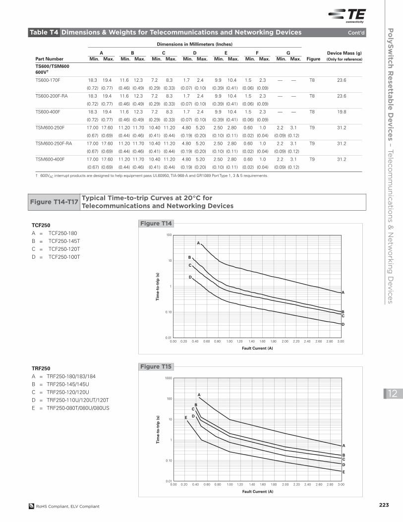
Table T4 Dimensions & Weights for Telecommunications and Networking Devices
Device Mass (g)(Only for reference)
BMin. Max.
CMin. Max.
DMin. Max.
EMin. Max.
FMin. Max.
GMin. Max.
Dimensions in Millimeters (Inches)
PolySwitchResetta
bleDevices–Telecommunications&NetworkingDevices
223RoHS Compliant, ELV Compliant
12
Tim
e-to
-tri
p(s
)
Fault Current (A)
100
10
1
0.10
0.010.00 0.20 0.40 0.60 0.80 1.00 1.20 1.40 1.60 1.80 2.00 2.20 2.40 2.60 2.80 3.00
A
A
B
B
C
D
C
D
Figure T14TCF250A = TCF250-180
B = TCF250-145T
C = TCF250-120T
D = TCF250-100T
Tim
e-to
-tri
p(s
)
Fault Current (A)
1000
100
10
1
0.10
0.010.00 0.20 0.40 0.60 0.80 1.00 1.20 1.40 1.60 1.80 2.00 2.20 2.40 2.60 2.80 3.00
A
A
BC
DE
BCD
E
Figure T15TRF250A = TRF250-180/183/184
B = TRF250-145/145U
C = TRF250-120/120U
D = TRF250-110U/120UT/120T
E = TRF250-080T/080U/080US
Figure T14-T17Typical Time-to-trip Curves at 20°C forTelecommunications and Networking Devices
Table T4 Dimensions & Weights for Telecommunications and Networking Devices Cont’d
TS600/TSM600600V†
TS600-170F 18.3 19.4 11.6 12.3 7.2 8.3 1.7 2.4 9.9 10.4 1.5 2.3 — — T8 23.6
(0.72) (0.77) (0.46) (0.49) (0.29) (0.33) (0.07) (0.10) (0.39) (0.41) (0.06) (0.09)
TS600-200F-RA 18.3 19.4 11.6 12.3 7.2 8.3 1.7 2.4 9.9 10.4 1.5 2.3 — — T8 23.6
(0.72) (0.77) (0.46) (0.49) (0.29) (0.33) (0.07) (0.10) (0.39) (0.41) (0.06) (0.09)
TS600-400F 18.3 19.4 11.6 12.3 7.2 8.3 1.7 2.4 9.9 10.4 1.5 2.3 — — T8 19.8
(0.72) (0.77) (0.46) (0.49) (0.29) (0.33) (0.07) (0.10) (0.39) (0.41) (0.06) (0.09)
TSM600-250F 17.00 17.60 11.20 11.70 10.40 11.20 4.80 5.20 2.50 2.80 0.60 1.0 2.2 3.1 T9 31.2
(0.67) (0.69) (0.44) (0.46) (0.41) (0.44) (0.19) (0.20) (0.10) (0.11) (0.02) (0.04) (0.09) (0.12)
TSM600-250F-RA 17.00 17.60 11.20 11.70 10.40 11.20 4.80 5.20 2.50 2.80 0.60 1.0 2.2 3.1 T9 31.2
(0.67) (0.69) (0.44) (0.46) (0.41) (0.44) (0.19) (0.20) (0.10) (0.11) (0.02) (0.04) (0.09) (0.12)
TSM600-400F 17.00 17.60 11.20 11.70 10.40 11.20 4.80 5.20 2.50 2.80 0.60 1.0 2.2 3.1 T9 31.2
(0.67) (0.69) (0.44) (0.46) (0.41) (0.44) (0.19) (0.20) (0.10) (0.11) (0.02) (0.04) (0.09) (0.12)
† 600VAC interrupt products are designed to help equipment pass UL60950, TIA-968-A and GR1089 Port Type 1, 3 & 5 requirements.
Part NumberA
Min. Max. FigureDevice Mass (g)(Only for reference)
BMin. Max.
CMin. Max.
DMin. Max.
EMin. Max.
FMin. Max.
GMin. Max.
Dimensions in Millimeters (Inches)
RoHS compliant, ELV compliant224
12
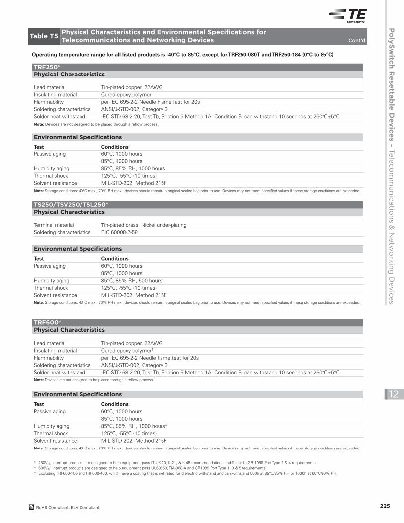
Tim
e-to
-tri
p(s
)
Fault Current (A)
1000
100
10
1
0.1
0.010 1 2 3 4 5 6 7
E
CB
A
D
E
A
BC
D
Figure T17TRF600/TS600/TSM600A = TRF600-400/TS600-400/
TSM600-400F
B = TSM600-250F/
TS600-170F/200F
C = TRF600-160
D = TR600-150F-EX
E = TRF600-150
Operating temperature range for all listed products is -40°C to 85°C, except forTRF250-080T andTRF250-184 (0°C to 85°C)
TCF250*
Terminal material Nickel-plated copper foil
Test ConditionsPassive aging 60°C, 1000 hours
85°C, 1000 hoursHumidity aging 85°C, 85% RH, 1000 hoursThermal shock 125°C, -55°C (10 times)Solvent resistance MIL-STD-202, Method 215FNote: Storage conditions: 40°C max., 70% RH max., devices should remain in original sealed bag prior to use. Devices may not meet specified values if these storage conditions are exceeded.
Physical Characteristics
Environmental Specifications
* 250VAC interrupt products are designed to help equipment pass ITU K.20, K.21, & K.45 recommendations and Telcordia GR-1089 Port Type 2 & 4 requirements.
Table T5Physical Characteristics and Environmental Specifications forTelecommunications and Networking Devices
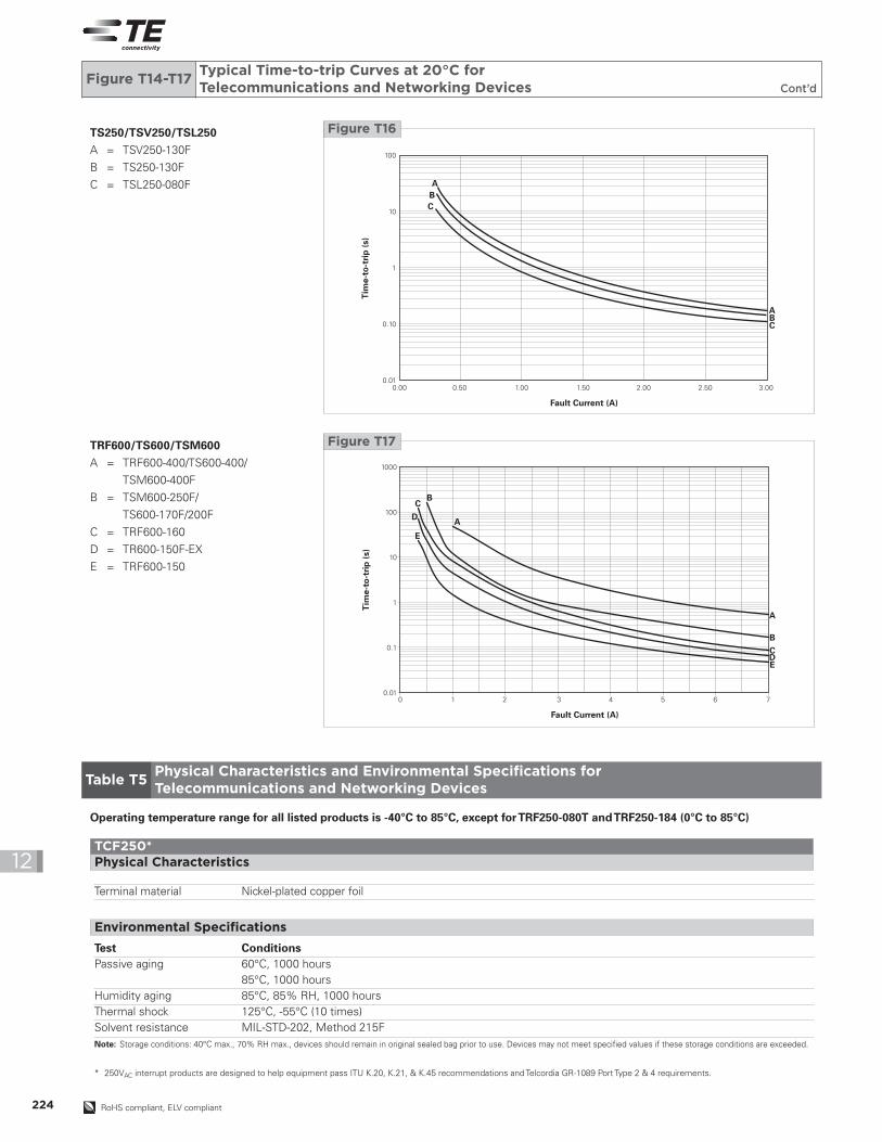
Figure T14-T17Typical Time-to-trip Curves at 20°C forTelecommunications and Networking Devices Cont’d
Tim
e-to
-tri
p(s
)
Fault Current (A)
100
10
1
0.10
0.010.00 0.50 1.00 1.50 2.00 2.50 3.00
A
ABC
BC
Figure T16TS250/TSV250/TSL250A = TSV250-130F
B = TS250-130F
C = TSL250-080F
PolySwitchResetta
bleDevices–Telecommunications&NetworkingDevices
225RoHS Compliant, ELV Compliant
12
Terminal material Tin-plated brass, Nickel under-platingSoldering characteristics EIC 60008-2-58
Test ConditionsPassive aging 60°C, 1000 hours
85°C, 1000 hoursHumidity aging 85°C, 85% RH, 500 hoursThermal shock 125°C, -55°C (10 times)Solvent resistance MIL-STD-202, Method 215FNote: Storage conditions: 40°C max., 70% RH max., devices should remain in original sealed bag prior to use. Devices may not meet specified values if these storage conditions are exceeded.
TS250/TSV250/TSL250*Physical Characteristics
Environmental Specifications
* 250VAC interrupt products are designed to help equipment pass ITU K.20, K.21, & K.45 recommendations and Telcordia GR-1089 Port Type 2 & 4 requirements.† 600VAC interrupt products are designed to help equipment pass UL60950, TIA-968-A and GR1089 Port Type 1, 3 & 5 requirements.‡ Excluding TRF600-150 and TRF600-400, which have a coating that is not rated for dielectric withstand and can withstand 500h at 85°C/85% RH or 1000h at 60°C/90% RH.
Lead material Tin-plated copper, 22AWGInsulating material Cured epoxy polymer‡
Flammability per IEC 695-2-2 Needle flame test for 20sSoldering characteristics ANSI/J-STD-002, Category 3Solder heat withstand IEC-STD 68-2-20, Test Tb, Section 5 Method 1A, Condition B: can withstand 10 seconds at 260°C±5°CNote: Devices are not designed to be placed through a reflow process.
TRF600†Physical Characteristics
Test ConditionsPassive aging 60°C, 1000 hours
85°C, 1000 hoursHumidity aging 85°C, 85% RH, 1000 hours‡
Thermal shock 125°C, -55°C (10 times)Solvent resistance MIL-STD-202, Method 215FNote: Storage conditions: 40°C max., 70% RH max., devices should remain in original sealed bag prior to use. Devices may not meet specified values if these storage conditions are exceeded.
Environmental Specifications
Operating temperature range for all listed products is -40°C to 85°C, except forTRF250-080T andTRF250-184 (0°C to 85°C)
Table T5Physical Characteristics and Environmental Specifications forTelecommunications and Networking Devices Cont’d
Lead material Tin-plated copper, 22AWGInsulating material Cured epoxy polymerFlammability per IEC 695-2-2 Needle Flame Test for 20sSoldering characteristics ANSI/J-STD-002, Category 3Solder heat withstand IEC-STD 68-2-20, Test Tb, Section 5 Method 1A, Condition B: can withstand 10 seconds at 260°C±5°CNote: Devices are not designed to be placed through a reflow process.
Test ConditionsPassive aging 60°C, 1000 hours
85°C, 1000 hoursHumidity aging 85°C, 85% RH, 1000 hoursThermal shock 125°C, -55°C (10 times)Solvent resistance MIL-STD-202, Method 215FNote: Storage conditions: 40°C max., 70% RH max., devices should remain in original sealed bag prior to use. Devices may not meet specified values if these storage conditions are exceeded.
TRF250*Physical Characteristics
Environmental Specifications

226 RoHS Compliant, ELV Compliant
12
Test ConditionsPassive aging 60°C, 1000 hours
85°C, 1000 hours
Humidity aging 85°C, 85% RH, 1000 hours
Storage humidity Per IPC/JEDEC J-STD-020A Level 2a
Thermal shock 125°C, -55°C (10 times)
Solvent resistance MIL-STD-202, Method 215J
Note: Storage conditions: 40°C max., 70% RH max., devices should remain in original sealed bag prior to use. Devices may not meet specified values if these storage conditions are exceeded.
† 600VAC interrupt products are designed to help equipment pass UL60950, TIA-968-A and GR1089 Port Type 1, 3 & 5 requirements.
Terminal material Tin-plated brass
Insulating material Nylon resin (UL94V-0), 1000V dielectric rating
Flammability IEC 695-2-2 Needle Flame Test for 20s
Soldering characteristics EIC60068-2-58, Method 7
Solder heat withstand IEC-STD 68-2-20, Test Tb, Section 5 Method 1A
TSM600†Physical Characteristics
Environmental Specifications
Operating temperature range for all listed products is -40°C to 85°C, except forTRF250-080T andTRF250-184 (0°C to 85°C)
Table T5Physical Characteristics and Environmental Specifications forTelecommunications and Networking Devices Cont’d
Test ConditionsPassive aging 60°C, 1000 hours
85°C, 1000 hours
Humidity aging 85°C, 85% RH, 1000 hours
Thermal shock 125°C, -55°C (10 times)
Solvent resistance MIL-STD-202, Method 215F
Note: Storage conditions: 40°C max., 70% RH max., devices should remain in original sealed bag prior to use. Devices may not meet specified values if these storage conditions are exceeded.
Terminal material Tin-plated brass
Insulating material Nylon resin (UL94V-0), 1000V dielectric rating
Flammability IEC 695-2-2 Needle Flame Test for 20s
Soldering characteristics ANSI/J-STD-002, Category 3
Solder heat withstand IEC-STD 68-2-20, Test Tb, Section 5 Method 1A
TS600†Physical Characteristics
Environmental Specifications
PolySwitchResetta
bleDevices–Telecommunications&NetworkingDevices
227RoHS Compliant, ELV Compliant
12
Chip* — 250VACTCF250
TCF250-100T 2,500 — 10,000 — —
TCF250-120T 2,500 — 10,000 — —
TCF250-145T 2,500 — 10,000 — —
TCF250-180 2,500 — 10,000 — UL
Radial-leaded* — 250VACTRF250
TRF250-055UT 500 — 10,000 — —
TRF250-080U 500 — 10,000 — UL, CSA, TÜV
TRF250-080U-2 — 1,500 7,500 — UL, CSA, TÜV
TRF250-080T 500 — 10,000 08F UL, CSA, TÜV
TRF250-110U 500 — 10,000 — UL, CSA, TÜV
TRF250-120 500 — 10,000 20F UL, CSA, TÜV
TRF250-120-2 — 1,500 7,500 20F UL, CSA, TÜV
TRF250-120T 500 — 10,000 20F UL, CSA, TÜV
TRF250-120T-2 — 1,500 7,500 20F UL, CSA, TÜV
TRF250-120U 500 — 10,000 20F UL, CSA, TÜV
TRF250-120U-2 — 1,500 7,500 20F UL, CSA, TÜV
TRF250-120UT 500 — 10,000 20F UL, CSA, TÜV
TRF250-145 500 — 10,000 45F UL, CSA, TÜV
TRF250-145-2 — 1,500 7,500 45F UL, CSA, TÜV
TRF250-145-RA 500 — 10,000 45F UL, CSA, TÜV
TRF250-145U 500 — 10,000 45F UL, CSA, TÜV
TRF250-145U-2 — 1,500 7,500 45F UL, CSA, TÜV
TRF250-183 500 — 10,000 83F UL, CSA, TÜV
TRF250-183-2 — 1,500 7,500 83F UL, CSA, TÜV
TRF250-184 500 — 10,000 84F UL, CSA, TÜV
Surface-mount* — 250VACTS250/TSL250/TSV250
TSL250-080F-2 — 1,500 7,500 T08 UL, CSA,TÜV
TS250-130F-2 — 1,500 7,500 T13 UL, CSA, TÜV
TSV250-130F-2 — 1,200 6,000 T13V UL, CSA, TÜV
Radial-leaded† — 600VACTRF600
TRF600-150 500 — 10,000 150F UL, CSA, TÜV
TRF600-150-2 — 1,500 7,500 150F UL, CSA, TÜV
TR600-150F-EX 500 — 10,000 150F UL, CSA
TR600-150F-EX-2 — 600 3,000 150F UL, CSA
TR600-150F-EX-RA-B-0.5 500 — 10,000 150F UL, CSA
TRF600-160 500 — 10,000 160F UL, CSA, TÜV
TRF600-160-2 — 600 3,000 160F UL, CSA, TÜV
TRF600-400 500 — 10,000 400F UL, CSA
Surface-mount† — 600VACTS600/TSM600
TS600-170F-2 — 300 900 T20 UL, CSA
TS600-200F-RA-2 — 300 900 T20 UL, CSA
TS600-400F-2 — 300 900 T40 UL, CSA
TSM600-250F-2 — 200 1,000 TSM600 UL, CSA
TSM600-250F-RA-2 — 200 1,000 TSM600 UL, CSA
TSM600-400F-2 — 200 1,000 TSM600 UL
Part NumberBag
QuantityTape & ReelQuantity
Standard PackageQuantity Part Marking Agency Recognition
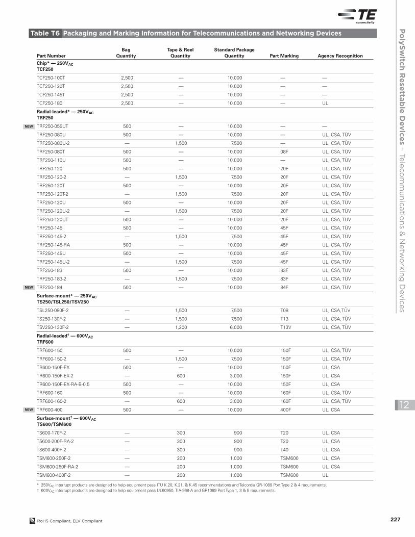
* 250VAC interrupt products are designed to help equipment pass ITU K.20, K.21, & K.45 recommendations and Telcordia GR-1089 Port Type 2 & 4 requirements.† 600VAC interrupt products are designed to help equipment pass UL60950, TIA-968-A and GR1089 Port Type 1, 3 & 5 requirements.
NEW
Table T6 Packaging and Marking Information for Telecommunications and Networking Devices
NEW
NEW
RoHS compliant, ELV compliant228
12
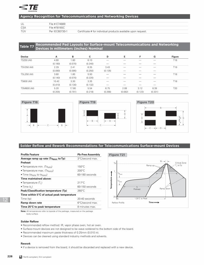
Solder Reflow and Rework Recommendations for Telecommunications Surface-mount Devices
Solder Reflow• Recommended reflow method: IR, vapor phase oven, hot air oven.• Surface-mount devices are not designed to be wave soldered to the bottom side of the board.• Recommended maximum paste thickness of 0.25mm (0.010 in).• Devices can be cleaned using standard industry methods and solvents.
Rework• If a device is removed from the board, it should be discarded and replaced with a new device.
Profile Feature Pb-Free AssemblyAverage ramp up rate (TsMAX toTp) 3°C/second max.
Preheat• Temperature min. (TsMIN) 150°C
• Temperature max. (TsMAX) 200°C
• Time (tsMIN to tsMAX) 60-180 seconds
Time maintained above:• Temperature (TL) 217°C
• Time (tL) 60-150 seconds
Peak/Classification temperature (Tp) 260°C
Time within 5°C of actual peak temperatureTime (tp) 20-40 seconds
Ramp down rate 6°C/second max.
Time 25°C to peak temperature 8 minutes max.
Critical ZoneTL to TpRamp up
t 25˚C to Peak
Reflow Profile Time
Ramp downts
Preheat
TsMAX
TL
Tptp
25
TsMIN
tL
Tem
per
atu
re
Figure T21
Note: All temperatures refer to topside of the package, measured on the packagebody surface.
Agency Recognition for Telecommunications and Networking Devices
UL File # E74889CSA File #78165CTÜV Per IEC60730-1 Certificate # for individual products available upon request.
Device A B C D E F G FigureTS250 (All) 4.60 1.80 6.10 — — — — T18
(0.180) (0.070) (0.240) — — — —
TSV250 (All) 2.29 2.41 6.35 3.43 — — — T19
(0.090) (0.095) (0.250) (0.135) — — —
TSL250 (All) 3.60 1.80 5.50 — — — — T18
(0.140) (0.070) (0.220) — — — —
TS600 (All) 10.42 3.30 3.35 — — — — T18
(0.410) (0.130) (0.132) — — — —
TSM600 (All) 5.20 17.80 5.54 6.75 2.08 3.12 8.39 T20
(0.205) (0.701) (0.218) (0.266) (0.082) (0.123) (0.331)
A
B C B
Figure T18
A
A
B B
C
D
Figure T19
A
B
C D
GE
F
Figure T20
Table T7Recommended Pad Layouts for Surface-mount Telecommunications and NetworkingDevices in millimeters (inches) Nominal

PolySwitchResetta
bleDevices–Telecommunications&NetworkingDevices
229RoHS Compliant, ELV Compliant
12
DimensionDescription EIA Mark IEC Mark Dimension (mm) Tolerance
Carrier tape width W W 18 -0.5/+1.0
Hold down tape width W4 W0 5 Minimum
Top distance between tape edges W6 W2 3 Maximum
Sprocket hole position W5 W1 9 -0.5/+0.75
Sprocket hole diameter D0 D0 4 ±0.2
Abcissa to plane (straight lead) H H 18.5 ±3.0
Abcissa to plane (kinked lead)* H0 H0 16 -0.5/+0.6
Abcissa to top H1 H1 32.2 Maximum
Overall width with lead protrusion — C1 43.2 Maximum
Overall width without lead protrusion — C2 42.5 Maximum
Lead protrusion L1 I1 1.0 Maximum
Protrusion of cut-out L L 11 Maximum
Protrusion beyond hold down tape I2 I2 Not specified —
Sprocket hole pitch P0 P0 12.7 ±0.3
Device pitch (TRF250 & TRF600-150) — — 12.7 —
Device pitch (TRF600-160/400) — — 25.4 —
Pitch tolerance — — 20 consecutive ±1
Tape thickness t t 0.9 Maximum
Tape thickness with splice* t1 — 2.0 Maximum
Splice sprocket hole alignment — — 0 ±0.3
Body lateral deviation h h 0 ±1.0
Body tape plane deviation p p 0 ±1.3
Lead spacing plane deviation P1 P1 0 ±0.7
Lead spacing* F F 5.08 ±0.6
Reel width w2 w 56 Maximum
Reel diameter a d 370 Maximum
Space between flanges less device w1 — 4.75 ±3.25
Arbor hole diameter c f 26 ±12.0
Core diameter n h 80 Maximum
Box — — 56/372/372 Maximum
Consecutive missing pieces* — — 3 maximum —
Empty places per reel* — — Not specified —
* Differs from EIA specification.
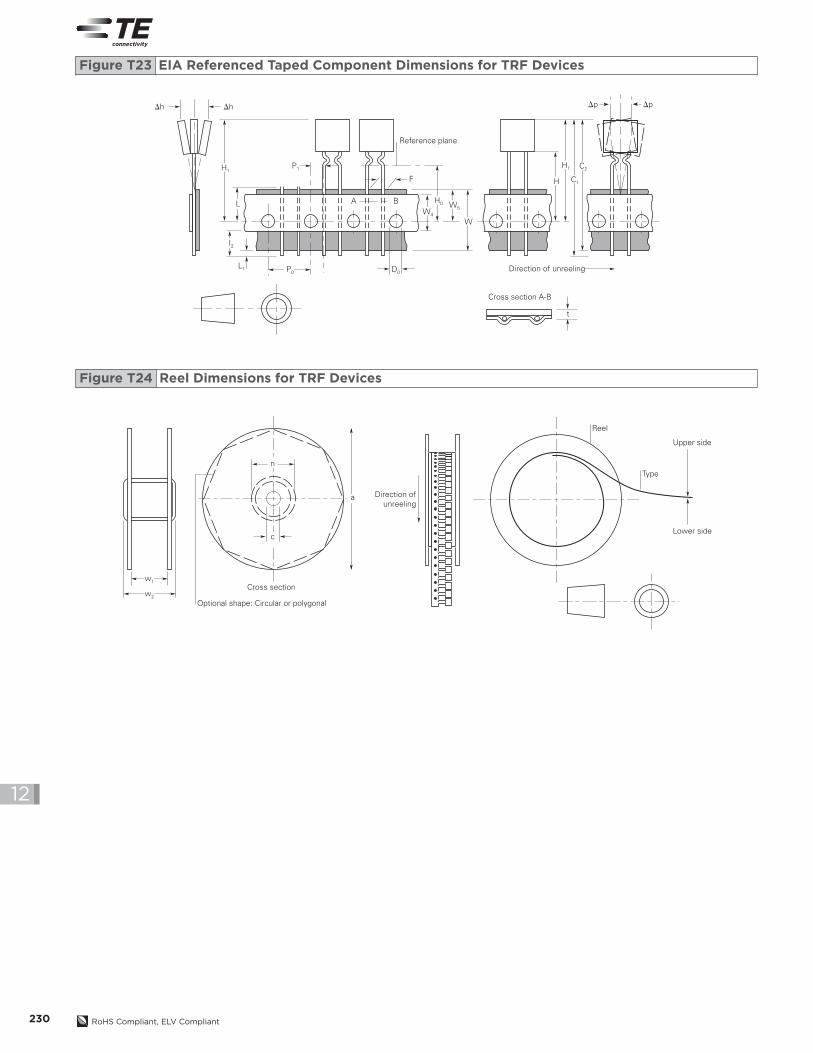
TRF250/TRF600 devices are available in tape and reel packaging per EIA 468-B standard. See Figures T23 and T24 for details.
Table T8TRF250/TRF600 Tape and Reel Specifications forTelecommunications and Networking Device
Wave Soldering and Rework Recommendations for Telecommunications Radial-leaded Devices
RecommendedWave Soldering• Soldering temperature profile
Temperature characteristic at component terminal with dualwave soldering
Rework• If a device is removed from the board, it should be discarded
and replaced with a new device.
300
250
200
150
100
50
00 50
10s
245˚C ... 260˚C
100˚C ... 130˚C
Forced cooling
100 150 200 250
Tem
per
atu
re(˚
C)
Time (s)
Figure T22
230 RoHS Compliant, ELV Compliant
12
w1
n
a
c
w2
Cross section
Direction ofunreeling
Reel
Type
Upper side
Lower side
Optional shape: Circular or polygonal
Figure T24 Reel Dimensions for TRF Devices
Dh
H1P1
W4
H0
H1
C1
C2
F
A B
Reference plane
Direction of unreeling
Cross section A-B
W5
H
W
t
P0 D0
I2
L
L1
Dh Dp Dp
Figure T23 EIA Referenced Taped Component Dimensions for TRF Devices
PolySwitchResetta
bleDevices–Telecommunications&NetworkingDevices
231RoHS Compliant, ELV Compliant
12
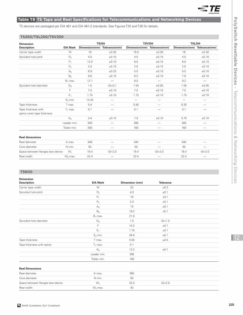
Carrier tape width W 16 ±0.30 16.0 ±0.30 16 ±0.30
Sprocket hole pitch P0 4.0 ±0.10 4.0 ±0.10 4.0 ±0.10
P1 12.0 ±0.10 8.0 ±0.10 8.0 ±0.10
P2 2.0 ±0.10 2.0 ±0.10 2.0 ±0.10
A0 6.9 ±0.23 5.5 ±0.10 5.5 ±0.10
B0 9.6 ±0.15 6.2 ±0.10 7.9 ±0.10
B1 max. 12.1 — 8.0 — 9.2 —
Sprocket hole diameter D0 1.5 -0/+0.1 1.55 ±0.05 1.55 ±0.05
F 7.5 ±0.10 7.5 ±0.10 7.5 ±0.10
E1 1.75 ±0.10 1.75 ±0.10 1.75 ±0.10
E2 min. 14.25 — — — — —
Tape thickness T max. 0.4 — 0.45 — 0.35 —
Tape thickness with T1 max. 0.1 — 0.1 — 0.1 —splice cover tape thickness
K0 3.4 ±0.15 7.0 ±0.10 3.70 ±0.10
Leader min. 300 — 390 — 390 —
Trailer min. 300 — 160 — 160 —
Reel dimensions
Reel diameter A max. 340 — 340 — 340 —
Core diameter N min. 50 — 50 — 50 —
Space between flanges less device W1 16.4 -0/+2.0 16.4 -0/+2.0 16.4 -0/+2.0
Reel width W2 max. 22.4 — 22.4 — 22.4 —
TS devices are packaged per EIA 481 and EIA 481-2 standards. See Figures T25 and T26 for details.
EIA MarkTS250
Dimension(mm) Tolerance(mm)TSV250
Dimension(mm) Tolerance(mm)TSL250
Dimension(mm) Tolerance(mm)DimensionDescription
TS250/TSL250/TSV250
Table T9 TS Tape and Reel Specifications for Telecommunications and Networking Devices
DimensionDescription EIA Mark Dimension (mm) Tolerance
Carrier tape width W 32 ±0.3
Sprocket hole pitch P0 4.0 ±0.1
P1 16 ±0.1
P2 2.0 ±0.1
A0 10 ±0.1
B0 19.2 ±0.1
B1 max. 21.6
Sprocket hole diameter D0 1.5 -0/+1.0
F 14.2 ±0.1
E1 1.75 ±0.1
E2 min. 28.4 ±0.1
Tape thickness T max. 0.50 ±0.5
Tape thickness with splice T1 max. 0.1
K0 13.2 ±0.1
Leader min. 390
Trailer min. 160
Reel Dimensions
Reel diameter A max. 360
Core diameter N min. 50
Space between flanges less device W1 32.4 -0/+2.0
Reel width W2 max. 40
TS600
232 RoHS Compliant, ELV Compliant
12
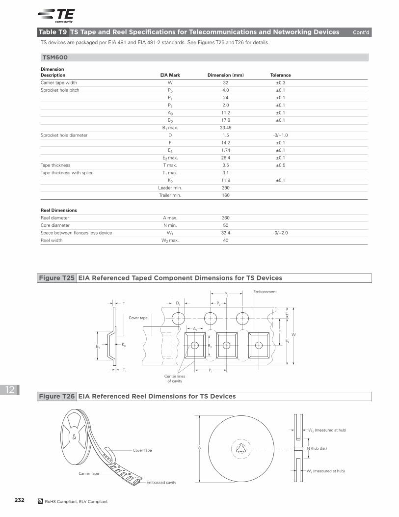
P0
E1
E2
FW
P2D0
A0
B0
P1
B1
T1
K0
T
Cover tape
Embossment
Center linesof cavity
ACover tape
Embossed cavity
Carrier tape
N (hub dia.)
W2 (measured at hub)
W1 (measured at hub)
Figure T25 EIA Referenced Taped Component Dimensions for TS Devices
Figure T26 EIA Referenced Reel Dimensions for TS Devices
TS devices are packaged per EIA 481 and EIA 481-2 standards. See Figures T25 and T26 for details.
Table T9 TS Tape and Reel Specifications for Telecommunications and Networking Devices Cont’d
DimensionDescription EIA Mark Dimension (mm) Tolerance
Carrier tape width W 32 ±0.3
Sprocket hole pitch P0 4.0 ±0.1
P1 24 ±0.1
P2 2.0 ±0.1
A0 11.2 ±0.1
B0 17.8 ±0.1
B1 max. 23.45
Sprocket hole diameter D 1.5 -0/+1.0
F 14.2 ±0.1
E1 1.74 ±0.1
E2 max. 28.4 ±0.1
Tape thickness T max. 0.5 ±0.5
Tape thickness with splice T1 max. 0.1
K0 11.9 ±0.1
Leader min. 390
Trailer min. 160
Reel Dimensions
Reel diameter A max. 360
Core diameter N min. 50
Space between flanges less device W1 32.4 -0/+2.0
Reel width W2 max. 40
TSM600
PolySwitchResetta
bleDevices–Telecommunications&NetworkingDevices
233RoHS Compliant, ELV Compliant
12
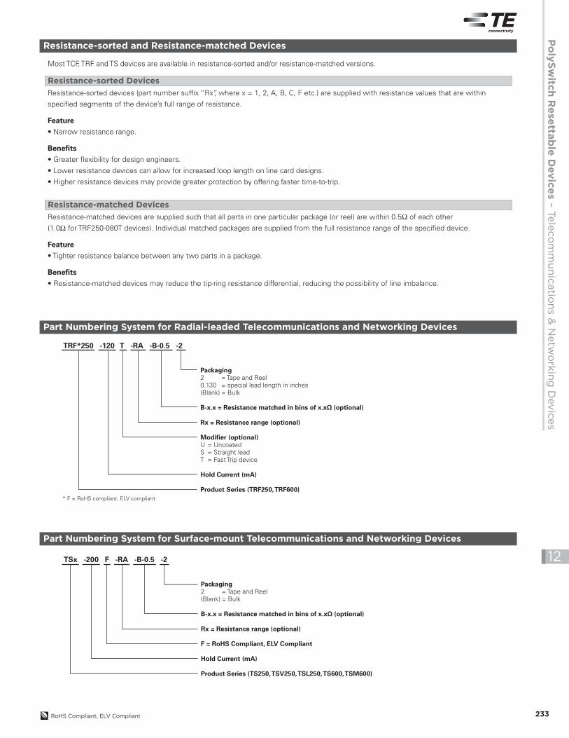
Resistance-sorted and Resistance-matched Devices
Resistance-sorted devices (part number suffix “Rx”, where x = 1, 2, A, B, C, F etc.) are supplied with resistance values that are within
specified segments of the device’s full range of resistance.
Feature• Narrow resistance range.
Benefits• Greater flexibility for design engineers.
• Lower resistance devices can allow for increased loop length on line card designs.
• Higher resistance devices may provide greater protection by offering faster time-to-trip.
Resistance-sorted Devices
Most TCF, TRF and TS devices are available in resistance-sorted and/or resistance-matched versions.
Resistance-matched devices are supplied such that all parts in one particular package (or reel) are within 0.5Ω of each other
(1.0Ω for TRF250-080T devices). Individual matched packages are supplied from the full resistance range of the specified device.
Feature• Tighter resistance balance between any two parts in a package.
Benefits• Resistance-matched devices may reduce the tip-ring resistance differential, reducing the possibility of line imbalance.
Resistance-matched Devices
Part Numbering System for Radial-leaded Telecommunications and Networking Devices
TRF*250 -120 T -RA -B-0.5 -2
Packaging2 = Tape and Reel0.130 = special lead length in inches(Blank) = Bulk
B-x.x = Resistance matched in bins of x.xΩ (optional)
Rx = Resistance range (optional)
Modifier (optional)U = UncoatedS = Straight leadT = Fast Trip device
Hold Current (mA)
Product Series (TRF250, TRF600)* F = RoHS compliant, ELV compliant
Part Numbering System for Surface-mount Telecommunications and Networking Devices
TSx -200 F -RA -B-0.5 -2
Packaging2 = Tape and Reel(Blank) = Bulk
B-x.x = Resistance matched in bins of x.xΩ (optional)
Rx = Resistance range (optional)
F = RoHS Compliant, ELV Compliant
Hold Current (mA)
Product Series (TS250,TSV250,TSL250,TS600, TSM600)
234 RoHS Compliant, ELV Compliant
12
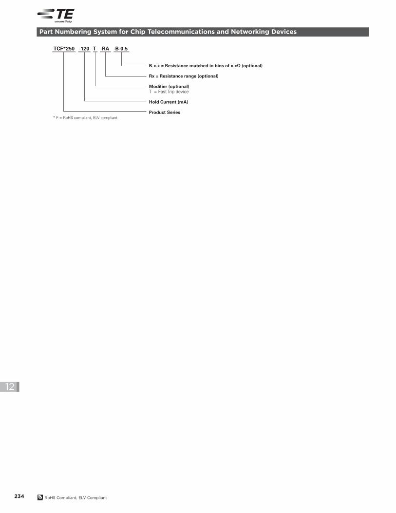
Part Numbering System for Chip Telecommunications and Networking Devices
TCF*250 -120 T -RA -B-0.5
B-x.x = Resistance matched in bins of x.xΩ (optional)
Rx = Resistance range (optional)
Modifier (optional)T = Fast Trip device
Hold Current (mA)
Product Series* F = RoHS compliant, ELV compliant