Embed Size (px)
Citation preview

1Lightning Tests: Telecom Test System
Telecom Test System
Ligh
tnin
g Te
sts
Brief Overview of Phenomena . . . . . . . . . . . . . . . . 2
Applicable Standards . . . . . . . . . . . . . . . . . . .3
Test System Overview . . . . . . . . . . . . . . . . . . . 4
Generator Specifications . . . . . . . . . . . . . . . . . . 8
Accessories and Options . . . . . . . . . . . . . . . . . 12
Software . . . . . . . . . . . . . . . . . . . . . . . 14
EMC PARTNER’s Product Range . . . . . . . . . . . . . . 15

2 Lightning Tests: Telecom Test System
Brief Overview of Phenomena
The most frequent cause of damage to telecommunication and data network equipment is overvoltages or overcurrents, caused by atmospheric discharges such as lightning, direct contact with adjacent power cables or coupling of interference signals from co-located cables. Overvoltages generated by lightning surge currents can disrupt or even destroy computer related products, process control equipment and data communica-tions equipment connected to the telephone line. Apart from interference on data lines, telecom equipment is also subjected to interference through the power interface. These can be surges generated by lightning or switching in the power network. If the interfer-ence source is in the same circuit as the electronic equipment, the transfer impedance is low and the impulse takes a current form. If the interference is from some external source, the transfer impedance will be higher and a voltage impulse results.
Telecommunications operators aim to maintain a network availability of 99.9%. In order to meet this goal, tests are performed to assess survivability and catastrophic failure of individual equipment. The objective being respectively to check for continued network operation and to ensure that failure does not lead to other equipment in the telephone exchange being damaged or destroyed.
Lightning transients are defined by the cable properties. Telecommunication lines are highly exposed and very long leading to a relatively long voltage impulse being trans-mitted to electronic interfaces. International telecommunications standards use the 10/700us impulse for telecommunication interfaces, a standard that is being adopted for ethernet and other fast data communication media.
EMC Partner telecom test systems are used to simulate transient (impulses) and also power contact or power induction in the public telephone network.
- Telecom interface impulses (10/700us, 10/160us & 10/560us) Used to simulate lightning impulses in long telecommunication lines. These impulses
are used to test telecom interfaces at the exchange and user premises. Application is through specialized Coupling De-coupling Networks (CDNs) that en-
able continuous traffic while the impulses are applied.
- Power interface impulses (CWG & 2/10us) A Combination Wave Generator (CWG) delivers voltage impulses (1.2/50us) into an
open circuit and current impulses (8/20us) into a short circuit. The 2/10us impulse is defined in FCC part 68 for power interface testing.
- Lightning Current (8/20) Lightning impulses coupled directly to the telecom line can generate currents with
very high amplitudes. Telecom interfaces that do not have primary protection ele-ments, must be tested for impulse current carrying capability.
These impulses are applied directly to non-active interfaces.
- Power Contact and Induction Co-located or adjacent power cables are an interference source that can induce
voltages into the telecom network. Power contact is direct connection between power lines and telecom lnes, caused by either line falling onto the other. This could occur during storms.
Typical power frequencies are 16.7 (for railway applications), 50 and 60Hz.
- ESD ESD can result from charging of personnel or equipment. Resultant waveforms and
test levels are dependant on location. ESD impulses are used to ensure equipment is not damaged during maintenance procedures.

3Lightning Tests: Telecom Test System
Applicable Standards
International Telecommunications Union (ITU)K.44 (2008): Resistibility tests for telecommunications equipment exposed to overvolt-ages and overcurrents - Basic recommendation
K.20 (2008): Resistibility of telecommunication equipment installed in a telecommunica-tions centre to overvoltages and overcurrents
K.21 (2008): Resistibility of telecommunication equipment installed in customer premises to overvoltages and overcurrents.
K.45 (2008): Resistability of telecommunication equipment installed in the access and trunck networks to overvoltages and overcurrents.
International Electrotechnical Committee (IEC)IEC 61000-4-5 Ed 2 (2005): Electromagnetic compatibility (EMC) - Testing and meas-urement techniques - Surge immunity test.
IEC60950-1 (2005): Information technology equipment - safety - Part 1: General re-quirements
American National Standards Institute (ANSI)ANSI / TIA 968-A (2004): Telephone Terminal Equipment - Technical requirements for connection of terminal equipment to the telephone network.
Federal Communnication Commission (FCC)47 cfr PART 68 (2005): Connection of terminal equipment to the the telephone net-work.

4 Lightning Tests: Telecom Test System
Test System Features - ITU basic level tests- ITU enhanced level tests- Power contact tests- Power induction tests- Application based solutions- Semiconductor high voltage circuits- Intuitive user interface- Telecom couplers up to 8 wires- Internal program memory- Electronic polarity change- Remote control and software upgrade through standard interface- Full range of accessories- 2 year warranty
User BenefitsThe technical excellence and many unique features of EMC PARTNER telecom test system translate directly into benefits for the user:
- Impulse repeatability eliminates costly re-tests- Fully reproducible test results between locations- Simple extension to meet future test needs- Increase quality of test object- Save operator time with the automated test routines and test report facility- Unparalleled reliability and system up-time
GeneratorsThe EMC PARTNER telecom test system comprises a range of instruments to simulate transient and EMC events that occur in the telecom network. EMC PARTNER telecom test system components are available to cover most international applications.
- MIG0603IN2 S-T The best solution for IEC, EN and ITU basic testing requirements. Both the com-
bination wave and 10/700us impulses up to 6kV are included. An integrated single phase CDN operates with EUT power up to 280V/16Aac and 110V/16Adc. A direct impulse output enables use of the EMC PARTNER telecom accessories.
- MIG0603FCC Telecom tester according to FCC part 68. This generator also includes a standard
combination wave for IEC, EN and ITU requirements as well as the 10/700us ITU impulse. FCC part 68 waveforms include the 2/10us power line and 10/160us, 10/560us and 9/720us telecom line impulses. An integrated single phase CDN op-erates with EUT power up to 280V/16Aac and 110V/16Adc. A direct impulse output enables use of the EMC PARTNER telecom accessories.
Test System Overview
MIG0603FCC
MIG0603IN2 S-T

5Lightning Tests: Telecom Test System
- MIG0603EN S-T-I A compact generator with three waveforms and two distinct applications. IEC/
EN60950 is an ITE safety standard that requires the 10/700us telecom impulse to-gether with a 1.2/50us voltage impulse. Both these are included in the MIG0603EN. Together with the “classic” combination wave, these impulses can also be applied for telecom testing according to ITU-T K.44, K.20 and K.21. An integrated single phase CDN operates with EUT power up to 280V/16Aac and 110V/16Adc. A direct impulse output enables use of the many EMC PARTNER telecom accessories.
- MIG1206-1P-T Ideal for ITU-T K.44, K.20 and K.21 basic and enhanced level testing, the MIG1206-
1P-T includes a combination wave generator up to 12kV and a 10/700us impulse up to 6kV. An integrated fully automatic CDN operates with EUT power up to 280V phase - neutral/PE and 32A. A direct impulse output enables the many EMC PART-NER telecom accessories such as the CDN-UTP to be used.
- MIG-1206-3P-T Similar to the MIG1206-1P-T, the MIG1206-3P-T is a three phase version with the
same impulse circuits. The fully automatic integrated three phase CDN operates with EUT power up to 480V phase to phase and 280V phase to neutral/PE. The MIG1206-3P-T is mounted in a rack with large wheels for ease of operation in the laboratory environment.
- MIG1203T T As an extension to the ITU-T K.44 enhanced level requirements, the MIG1203T
provides a 10/700us impulse up to 12kV with high voltage outputs on top of the generator protected by a TC-MIG24 test cabinet which is connected to the generator safety circuit. MIG1203T has many options which expand the generator capability to include IEC60950, IEC61000-4-5 and ITU-T K.20, K.21 basic level.
As options for the MIG1203T, a combination wave, 1.2/50us and 10/1000us voltage impulses up to 12kV are available.
- MIG0624TEL Lightning current test requirements in ITU-T K.20 and K.21 specify use of an 8/20us
impulse on telecom lines. MIG0624TEL has four independant outputs so if one line is short circuit the current delivered by the generator is limited to the maximum requirement for the standard.
- MIG0648TEL Similar to the MIG0624TEL, the MIG0648TEL comprises eight independant outputs
to enable testing of telecom interfaces up to enhanced level.
- MIG-ITU-K44 Specifically designed for the power induction tests in ITU-T K.44, MIG-ITU-K44
generates a short duration AC output up to 1,500Vac. Both basic and enhanced levels can be reached up to the 10 A2 s energy requirement. An integrated variac allows easy adjustment of output voltage.
- MIG0612T-K12 A dual output surge current generator designed for testing both two and three elec-
trode gas arresters. This generator includes the 10/1000us, 8/20us and 40/350us (10/350us) current impulses up to 12kA. The TC-MIG24 provides operator safety through the integrated safety circuit.
- MIG0624T-K12 Similar to the MIG0612T-K12, this generator extends the maximum impulse current
capability to 24kA for the 8/20us impulse. TC-MIG24 is a must for this generator.
Remote control of EMC PARTNER telecom test systems is possible using either the EMC PARTNER TEMA or GENECS-MIG software packages.
A wide range of accessories are available to facilitate testing. Four or eight wire coupling devices for active telecom interfaces including Ethernet complete the system.
MIG0603EN S-T-I
MIG1206-1P-T
MIG0624TEL
MIG-ITU-K44

6 Lightning Tests: Telecom Test System
System FlowchartsThe following flowcharts illustrate EMC PARTNER equipment configurations neces-sary to perform transient, power contact and power induction tests in accordance with telecoms standards.
FCC part68
ITU Telecom Basic Level
NW March. 2009
VAR-EXT1000
EUT
TEMA TEST MANAGERcustomized solution
DSO Optioncontrol TEK DSO
CDN-UTP(8)NW-K44-PC
Power Port
ITU Telecom Basic Level Tests
TRA2000IN6
TRA OPTION NW-K44-PI
Telecom Port
Telecom Port
PowerPort
Telecom Port/ Power Port
MIG0624TEL
PCPI160E
NW March. 2009
EUT
TEMA TEST MANAGERcustomized solution
DSO Optioncontrol TEK DSO
CDN-UTP(8)
FCC Part 68 Tests
MIG0603FCC
Telecom Port
PowerPort
CDN2000-06-32

7Lightning Tests: Telecom Test System
ITU Telecom Enhanced Level
ITU Telecom Component (Gas Discharge Tubes)
MIG0603IN2 S-T or
MIG0603EN S-T-I
NW March 2009
MIG1206-xP-T
EUT
TEMA TEST MANAGERcustomized solution
DSO Optioncontrol TEK DSO
CDN-UTP(8)
ITU Telecom Enhanced Level Tests
MIG-ITU-K44
Telecom Port
PowerPort
Power Port
MIG0648TEL
NW March 2009
EUT
TEMA TEST MANAGERcustomized solution
DSO Optioncontrol TEK DSO
ITU Telecom Component Tests
MIG0612T-K12 MIG0624T-K12
TC-MIG24

8 Lightning Tests: Telecom Test System
MIG0603IN2 S-T
Combination Wave 1 .2/50us (8/20us)Voltage range 0.25 up to 6kVPulse front time 1.2 µsPulse duration 50 µsCurrent range 0.125 up to 3kAPulse front time 8 µsPulse duration 20 µsSource impedance 4ohmCoupling path selection automaticCoupling paths L - N (18uF), L - PE (9uF) & N - PE (9uF)Maximum voltage on CDN 280Vac 50/60Hz
Maximum current 16A
10/700us Telecom waveVoltage range 0.25 up to 6kVRisetime 10 µsDuration 700 µsSource impedance 15ohmsDamping resistor 25ohmsCurrent range 12.5 up to 150A
MIG0603FCC
Combination Wave 1 .2/50us (8/20us)Voltage range 0.25 up to 6kVPulse front time 1.2 µsPulse duration 50 µsCurrent range 0.125 up to 3kAPulse front time 8 µsPulse duration 20 µsSource impedance 2ohm
Combination wave 2/10us (2/10us)Voltage range 0.125 up to 3kVPulse front time 1.54 µsPulse duration 12.5 µsCurrent range 0.125 up to 1.2kAPulse front time 1.54 µsPulse duration 12.5 µsSource impedance 2.5ohm
Integrated Single Phase CDNCoupling path selection automaticCoupling paths L - N (18uF), L - PE (9uF) & N - PE (9uF)Maximum voltage on CDN 280Vac 50/60Hz
Maximum current 16A
Generator Specifications
Telecom test system up to 6kV

9Lightning Tests: Telecom Test System
9/720us Telecom waveVoltage range 0.25 up to 6kVRisetime 9 µsDuration 720 µsSource impedance 15ohmsDamping resistor 25ohmsCurrent range 6.25 up to 157A
10/160us Telecom waveVoltage range 0.25 up to 2kVRisetime 7.7 µsDuration 200 µsSource impedance 7.5ohmsCurrent range 33 up to 266A
10/560us Telecom waveVoltage range 0.25 up to 1kVRisetime 7.7 µsDuration 700 µsSource impedance 8ohmsCurrent range 31 up to 125A
MIG0603EN S-T-I
Combination Wave 1 .2/50us (8/20us)Voltage range 0.25 up to 6kVPulse front time 1.2 µsPulse duration 50 µsCurrent range 0.125 up to 3kAPulse front time 8 µsPulse duration 20 µsSource impedance 2ohmCoupling path selection automaticCoupling paths L - N (18uF), L - PE (9uF) & N - PE (9uF)Maximum voltage on CDN 280Vac 50/60HzMaximum current 16A
Voltage Impulse 1 .2/50us (1uF)Voltage range 0.25 up to 6kVPulse front time 1.2 µsPulse duration 50 µsPulse Capacitor 1uFParallel Resistor 76ohmSeries Resistor 13ohmDamping Resistor 25ohm
10/700us Telecom waveVoltage range 0.25 up to 6kVRisetime 10 µsDuration 700 µsSource impedance 15ohmsDamping resistor 25ohmsCurrent range 12.5 up to 150A

10 Lightning Tests: Telecom Test System
Telecom Test System up to 12kV
MIG1203T T
10/700us Telecom waveVoltage range 0.5 up to 12kVRisetime 10 µsDuration 700 µsSource impedance 15ohmsDamping resistor 25ohmsCurrent range 25 up to 300A
OPTIONS TO MIG1203T1.2-50-1 Voltage Impulse (T-I) up to 12kVCWG Combination Wave (T-S) up to 6kV
MIG1206-1P-T
Combination Wave 1 .2/50us (8/20us)Voltage range 0.5 up to 12kVPulse front time 1.2 µsPulse duration 50 µsCurrent range 0.25 up to 6kAPulse front time 8 µsPulse duration 20 µsSource impedance 2ohmCoupling path selection automaticCoupling paths L - N, L - PE, N - PE
L + N - PEMaximum voltage on CDN 280Vac 50/60HzMaximum current 32A
10/700us Telecom waveVoltage range 1 up to 6kVRisetime 10 µsDuration 700 µsSource impedance 15ohmsDamping resistor 25ohmsMaximum Current 400A
MIG1206-3P-T
Combination Wave 1 .2/50us (8/20us)Voltage range 0.5 up to 12kVPulse front time 1.2 µsPulse duration 50 µsCurrent range 0.25 up to 6kAPulse front time 8 µsPulse duration 20 µsSource impedance 2ohmCoupling path selection automaticCoupling paths Lx - Lx, Lx - N, Lx - PE, N - PE
L1 + L2 + L3 + N - PEMaximum voltage on CDN Lx - Lx 480Vac Lx - N/PE 280Vac 50/60HzMaximum current 32A
11Lightning Tests: Telecom Test System
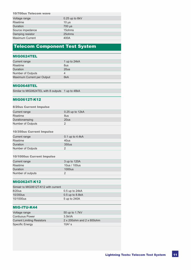
10/700us Telecom waveVoltage range 0.25 up to 6kVRisetime 10 µsDuration 700 µsSource impedance 15ohmsDamping resistor 25ohmsMaximum Current 400A
Telecom Component Test System
MIG0624TELCurrent range 1 up to 24kARisetime 8usDuration 20usNumber of Outputs 4Maximum Current per Output 6kA
MIG0648TELSimilar to MIG0624TEL with 8 outputs 1 up to 48kA
MIG0612T-K12
8/20us Current ImpulseCurrent range 0.25 up to 12kARisetime 8usDurationamping 20usNumber of Outputs 2
10/350us Current ImpulseCurrent range 0.1 up to 4.4kARisetime 40usDuration 350usNumber of Outputs 2
10/1000us Current ImpulseCurrent range 3 up to 120ARisetime 10us / 100usDuration 1000usNumber of outputs 2
MIG0624T-K12Simialr to MIG0612T-K12 with current8/20us 0.5 up to 24kA10/350us 0.5 up to 8.8kA10/1000us 5 up to 240A
MIG-ITU-K44Voltage range 50 up to 1.7kVContiuous Power 3.5kVACurrent Limiting Resistors 2 x 200ohm and 2 x 600ohmSpecific Energy 10A2 s

12 Lightning Tests: Telecom Test System
NW-K44PC
NW-K44PCNetwork for mains power contact according to ITU-T K.44, K.20, K.21. Includes current limiting resistors 2 x 300, 2 x 600, 2 x 1000 and 2 x 1200 ohm. Also features a direct output for use with external limiting resistors such as the PCPI160E.
Requires TRA2000INx with DIP circuit.
Accessories and Options
TRA OPTION NW-K44PI
TRA OPTION NW-K44PIOption to NW-K44PC. Coupling network for power induction tests, basic level, ac-cording to ITU-T K.44, K.20, K.21. Includes transformer for 600V output and current limiting resistors 2 x 200 and 2 x 600 ohm. TRA OPTION NW-K44PI can only be used together with the NW-K44PC
Requires TRA2000INx with DIP circuit.
PCPI160EPower contact current limiting resistor network for telecom testing in accordance with ITU-T K.44, K.20, K.21. Resistor values of; 10, 20, 40, 80 and 160 ohm are avaial-ble.
For use with NW-K44PC
Two PCPI160E units may be required for 4 wire testing.
PCPI160E (one unit shown)
CN10-700E252 wire telecom coupling module for impulses up to 6kV. For use with 10/700us and 8/20us impulses. Coupling 2 x GDTs (90V) in parallel with 0.1uF capacitor. 2 x 25ohm.
CN10-700E25
CN10-700E102 wire telecom coupling module for impulses up to 6kV. For use with 10/700us and 1.2/50us impulses. 2 x 10ohm. For use with CDN-UTP or CDN-UTP8.
CN10-700E10

13Lightning Tests: Telecom Test System
NW-K17-1P2 wire telecom coupling module for impulses up to 6kV. For use with 10/700us and CWG impulses. Coupling 2 x GDTs (90V). 20mH decoupling inductors.
NW-K17-1P
CDN-UTPThe CDN-UTP is a sophisticated coupling and de-coupling network for superimposing surge impulses on balanced communication lines in accordance with IEC 61000-4-5 (Figure 12: unshielded symmetrical interconnection lines), ITU-K20, K21 and FCC part 68.
It is designed for 1.2/50µs and 10/700µs pulses up to 6.6kV.
CDN-UTP is also available with 4 pairs (8 lines) as the CDN-UTP8 version. CDN-UTP
CDN-UTP8The CDN-UTP is a sophisticated coupling and de-coupling network for superimposing surge impulses on balanced communication lines in accordance with IEC 61000-4-5 (Figure 12: unshielded symmetrical interconnection lines), ITU-K20, K21 and FCC part 68.
It is designed for 1.2/50µs and 10/700µs pulses up to 6.6kV.
CDN-UTP is also available with 4 pairs (8 lines) as the CDN-UTP8 version.
CDN-UTP8
External Three Phase CouplersCombination and Ring wave testers can be extended with automatic or manual three-phase coupling networks. The CDN2000-06-25 and CDN2000A-06-32 can also be used for EFT/Burst. Coupling path selection is either from the MIG firmware, from GENECS and TEMA software or manually on the CDN front panel (manual version only). The coupling networks fulfill the requirements laid down in the IEC 61000-4-4, IEC 61000-4-5, IEC 61000-4-12 (ring wave) and ANSI C62.41 standards.
MIG Generator Three Phase CDNModel Internal CDN Model EUT VoltageMIG0603IN2 Yes CDN2000-06-32 or
CDN2000A-06-32280V Lx to N/PE 480V Lx - Lx
MIG0603EN Yes CDN2000-06-32 or CDN2000A-06-32
280V Lx to N/PE 480V Lx - Lx
MIG0603FCC Yes CDN2000-06-32 or CDN2000A-06-32
280V Lx to N/PE 480V Lx - Lx
Note: CDN2000-06-25 can be used for Combination wave, Ring wave and EFT testing. With an EMC PARTNER oscillatory wave tester, power and up to four data lines using the 100kHz and 1MHz oscillatory waves can be tested according to IEC61000-4-18.
CDN2000-06-32
CDN2000A-06-32
ADAPTER BOX 200EThe ADAPTER Box 200E can be plugged on the front of the CDN-UTP and CDN-UTP8 as shown in the figure below. The standard banana cables of the CDN-UTP and CDN-UTP8 can be used for EUT and AUX connections..
ADAPTER BOX 200E

14 Lightning Tests: Telecom Test System
For remote control of EMC PARTNER military generators, one of the following software packages is needed:
- GENECS-MIG. This is a relatively simple program that reproduces generator front panel functions on a PC. In addition to remote programming and control of the gen-erators, test report information is available to word processing or other evaluation programs such as EXCEL.
- TEMA Software. Comfortable control of EMC PARTNER generators from a PC. Enables several generator types to be included in the same test sequence. Gener-ates an enhanced level of test report.
Predefined test routines
SoftwareTC-MIG24
TC-MIG24A test cabinet for EUT with maximum dimensions 12 x 15 x 28cm. Can be used together with all Telecom Device Testers with the outputs on top. These include MIG0612T-K12 and MIG0624T-K12
TC-MIG24 is linked to the MIG tester safety circuit. Opening the test cabinet disables test voltages. Safety circuit status is indicated by red and green lamps in the test cabinet.

15Lightning Tests: Telecom Test System
EMC PARTNER’s Product RangeHidden Heading to provoke a TOC entry
EMC PARTNER’s Product RangeThe Largest Range of Impulse Test Equip ment up to 100kA and 100kV.
Lightning TestsA range of test equipment and accessories for aircraft, military and telecom applica-tions. Complete solutions including all hardware and software to meet the require-ments of RTCA / EUROCAE DO160 / ED14 for indirect lighting on aircraft systems, MIL-STD-461 tests CS106, CS115, CS116, for military vehicles, ITU-T .K44 basic and enhanced tests for impulse, power contact and power induction, FCC part 68 for and enhanced tests for impulse, power contact and power induction, FCC part 68 for telecom equipment testing.
Component TestsModular impulse gen er a tors (MIG) for transient com po nent testing on: varistors, gas discharge tubes (GDT), surge pro tec tive devices (SPD), X Y ca pac i tors, cir cuit break ers, watt-hour meters, pro tec tion re lays, in su la tion ma te ri al, sup pres sor di odes, con nec tors, chokes, fus es, re sis tors, emc-gaskets, ca bles, etc. Manual or fully automated solutions are available up to 100kA (8/20us) and 144kV (1.2/50us).
Emission MeasurementsOne unit per forms all meas ure ments on the power sup plies of elec tron ic equip ment and prod ucts for the CE-Mark. HAR1000 uses a novel techniques to deliver clean pow er prod ucts for the CE-Mark. HAR1000 uses a novel techniques to deliver clean pow er source for the EUT in a compact and lightweight form. The system includes all hardware and software including line im ped ance net works, control and evaluation software. A and software including line im ped ance net works, control and evaluation software. A basic 1-phase system can be easily extended to 3-phase by adding 2 further phases . HARCS Immunity soft ware further expands the system by addidng interharmonic tests, voltage variation and ripple on DC tests. Com plies with IEC / EN 61000-3-2, -3 IEC / EN 61000-4-13, -14,
Immunity TestsTransient Test System can be used to per forms all EMC tests on elec tron ic equip ment. ESD, EFT, surge, AC dips, AC mag net ic fi eld, surge mag net ic fi eld, com mon mode, damped oscillatory and DC dips tests are available as stand-alone or combined test instruments. A large range of ac ces so ries for dif fer ent ap pli ca tions is avail a ble: three phase cou plers up to 690V/100A, telecom and data line couplers, ver i fi ca tion sets, magnetic fi eld coils. Immunity test systems fulfi lls IEC and EN 61000-4-2, -4, -5, -8, -9, -11, -12, -16, -18, -29.
Immunity Testers
www.emc-partner.com
MIG2000-6 – a flexible solution for military and avionic applications
MIG1212CAP – an automatic 8 bank capacitor test system
System AutomationAs addition to the basic generators, a range of accessories are available to enhance capability. Test cabinets, test pistols, adapters and software, simplify interfacing with the EUT.
PS3 programmable source is an EMC hardened supply for frequencies form 16.7Hz to 400Hz. Frequency variation tests can be made using the PS3-SOFT-EXT. Complies with IEC / EN 61000-4-28
HAR1000-3P and HARCS software a complete test system
PS3 - programmable source ideal for EMC applications
TRA3000 and ESD3000 ideal for CE testing Easily extended to meet other applications
Lightning Testers
www.emc-partner.com
Emission Measurement
www.emc-partner.com
System Automation
www.emc-partner.com

16 Lightning Tests: Telecom Test System
For further information please do not hesitate to contact EMC PARTNER’s representa-tive in your region. You will find a complete list of our representatives and a lot of other useful information on our website:
The Headquarters in SwitzerlandEMC PARTNER AG Baselstrasse 160 CH - 4242 Laufen Switzerland
Phone: +41 61 775 20 30 Fax: +41 61 775 20 59 Email: [email protected] Web-Site: www.emc-partner.com
Your local representative
www .emc-partner .com
Version 01. Sept. 2011 Subject to change without notice.