Embed Size (px)
Citation preview
Telecentric lenses2014
www.opto-engineering.com

2
www.opto-engineering.com
Descrizione
Titolo
Bi-Telecentric lenses
Telecentric lenses
Index
Opto Engineering Telecentric lenses represent our core business:
these products benefit from a decade-long effort in progressive
research & development, resulting in an extensive range of part numbers
for a diverse and ever-growing number of applications.
These products deliver the highest optical performances available
on the market:
• extra-telecentricity for thick object imaging
• very low distortion for accurate measurements
• excellent resolution for small pixel cameras
• wide field depth for large object displacements
• pre-adjusted back focal length and working distance
• compact and robust design, tailored for industrial environments
TC lenses for matrix detectors also feature:
• bi-telecentric design
• detailed test report for each lens
Opto Engineering testing procedures have been checked by TÜV Rheinland.
ACCESSORIES
Our TC family is complemented by a full set of accessories:
Please refer to our website www.opto-engineering.com to browse our complete product range.
CLAMPING MECHANICS RING LED ILLUMINATORS ... AND MORE

www.opto-engineering.com
Bi-telecentric lenses for matrix detectors up to 2/3’’ 4TC series
Bi-telecentric lenses for large detectors up to 1.2’’ 6TC2M-TC4M series
Telecentric lenses for 12 k and 16 k pixel linescan cameras 10TC12K series
Bi-telecentric lenses for 35 mm and 4 k / 8 k pixel line detectors 8TC16M series
TC optical bench kits for easy measurements 14TCBENCH series
Collimated (telecentric) LED illuminators 12LTCL series

4
www.opto-engineering.com
DO YOU KNOW?
Opto Engineering provides fully localizeddocumentation of the complete product range,with schematics and in-depth specifications.Available for download at:www.opto-engineering.com
Telecentric lenses | TC series
Bi-telecentric lenses for matrix detectors up to 2/3’’
TC series
Bi-telecentric lenses are the key component of any accurate measurement system based on machine vision technologies.
Compatible with high resolution/small pixel detectors like 5 Mpx 2/3” detectors, these lenses feature very low distortion while their real bi-telecentricity makes them purely telecentric.
It’s easy to select the right lens for your application by means of its part number: for any given product part number, i.e. TC xx yyy, “xx” gives the camera sensor format size (13 = 1/3”; 12 = 1/2”; 23 = 2/3”) while “yyy” expresses the horizontal field of view (FOV) in millimeters.For instance, a TC 12 064 features a field of view of 64 (x 48) mm with a 1/2” camera sensor.
Opto Engineering testing procedures have been checked by TÜV Rheinland.TÜVRheinland®

5
www.opto-engineering.com
1 Working distance: distance between the front lens and the object. Set this distance within +/- 3% of the nominal value for maximum resolution and minimum distortion.2 Working F-number: the real F-number of a lens when used as a macro. Lenses with smaller apertures can be supplied on request. 3 Maximum slope of chief rays inside the lens: when converted to milliradians, it gives the maximum measurement error for any millimeter of object displacement. Typical (average production) values and maximum (guaranteed) values are listed.4 Percent deviation of the real image compared to an ideal, undistorted image: typical (average production) values and maximum (guaranteed) values are listed.
5 At the borders of the field depth the image can be still used for measurement but, to get a perfectly sharp image, only half of the nominal field depth should be considered.6 Measured from the front end of the mechanics to the camera flange.7 With 1/1.8” (9 mm diagonal) detectors, the FOV of TC 12 yyy lenses may show some vignetting at the image corners, as these lenses are optimized for 1/2” detectors (8 mm diagonal).8 For the fields with the indication “Ø =”, the image of a circular object of such diameter is fully inscribed into the detector.
Detector type Optical specifications Dimensions 1/3’’ 1/2.5’’ 1/2’’ 1/1.8” 2/3” - 5 Mpx
Part Mag. Image w x h w x h w x h w x h w x h W.D. F/N Telecentricity Distortion Field CTF Mount Length Diam.
number circle 4.80 x 3.60 5.70 x 4.28 6.40 x 4.80 7.13 x 5.37 8.45 x 7.07 typical (max) typical (max) depth @70lp/mm
(x) (mm) (mm x mm) (mm x mm) (mm x mm) (mm x mm) (mm x mm) (mm) (deg) (%) (mm) (%) (mm) (mm)
7 1 2 3 4 5 6
Object field of view (mm x mm) 8TC 23 004 2.000 11.0 2.40 x 1.80 2.85 x 2.14 3.20 x 2.40 3.56 x 2.68 4.22 x 3.55 57.1 11 < 0.08 (0.10) < 0.04 (0.08) 0.23 > 30 C 101.4 28
TC 23 007 1.333 11.0 3.60 x 2.70 4.28 x 3.21 4.80 x 3.60 5.35 x 4.03 6.34 x 5.30 61.2 11 < 0.08 (0.10) < 0.03 (0.08) 0.5 > 30 C 78.5 28
TC 23 009 1.000 11.0 4.80 x 3.60 5.70 x 4.28 6.40 x 4.80 7.13 x 5.37 8.44 x 7.06 63.3 11 < 0.08 (0.10) < 0.04 (0.08) 0.9 > 25 C 65.0 28
TC 23 012 0.735 11.0 6.54 x 4.90 7.77 x 5.82 8.72 x 6.54 9.71 x 7.31 11.5 x 9.62 53.9 11 < 0.04 (0.10) < 0.04 (0.10) 1.2 > 25 C 60.3 28
TC 12 016 0.385 8.0 12.5 x 9.36 14.8 x 11.1 16.6 x 12.5 18.5 x 14.0 Ø = 18.4 45.3 8 < 0.04 (0.10) < 0.04 (0.08) 5 > 40 C 93.0 37.7
TC 23 016 0.528 11.0 9.09 x 6.82 10.8 x 8.10 12.1 x 9.09 13.5 x 10.2 16.0 x 13.4 45.3 8 < 0.06 (0.10) < 0.04 (0.07) 2 > 30 C 112.7 37.7
TC 12 024 0.255 8.0 18.8 x 14.1 22.4 x 16.8 25.1 x 18.8 28.0 x 21.1 Ø = 27.7 69.2 8 < 0.08 (0.10) < 0.04 (0.08) 10 > 45 C 117.8 44
TC 23 024 0.350 11.0 13.7 x 10.3 16.3 x 12.2 18.3 x 13.7 20.4 x 15.3 24.1 x 20.2 69.2 8 < 0.08 (0.10) < 0.04 (0.10) 5 > 45 C 137.5 44
TC 13 036 0.133 6.0 36.0 x 27.0 Ø = 32.0 Ø = 36.0 Ø = 40.2 n.a. 103.5 8 < 0.04 (0.08) < 0.03 (0.08) 38 > 50 C 133.0 61
TC 12 036 0.177 8.0 27.1 x 20.3 32.2 x 24.1 36.1 x 27.1 40.2 x 30.3 Ø = 39.9 103.5 8 < 0.03 (0.08) < 0.04 (0.10) 21 > 40 C 145.2 61
TC 23 036 0.243 11.0 19.7 x 14.8 23.4 x 17.6 26.3 x 19.7 29.3 x 22.1 34.7 x 29.0 103.5 8 < 0.04 (0.08) < 0.04 (0.10) 11 > 40 C 164.9 61
TC 13 048 0.098 6.0 48.8 x 36.6 Ø = 43.5 Ø = 48.8 Ø = 54.6 n.a. 134.6 8 < 0.08 (0.10) < 0.06 (0.10) 65 > 40 C 167.9 75
TC 12 048 0.134 8.0 35.9 x 26.9 42.5 x 31.9 47.8 x 35.9 53.3 x 40.1 Ø = 52.8 134.6 8 < 0.07 (0.10) < 0.06 (0.10) 37 > 40 C 181.5 75
TC 23 048 0.184 11.0 26.1 x 19.6 31.0 x 23.3 34.8 x 26.1 38.8 x 29.2 46.0 x 38.4 134.6 8 < 0.08 (0.10) < 0.05 (0.10) 20 > 40 C 201.0 75
TC 12 056 0.114 8.0 42.0 x 31.5 49.9 x 37.4 56.0 x 42.0 62.3 x 46.9 Ø = 61.8 159.3 8 < 0.04 (0.08) < 0.04 (0.08) 51 > 50 C 205.0 80
TC 23 056 0.157 11.0 30.6 x 22.9 36.3 x 27.2 40.7 x 30.6 45.4 x 34.2 53.8 x 45.0 159.3 8 < 0.05 (0.08) < 0.03 (0.08) 27 > 45 C 225.0 80
TC 13 064 0.074 6.0 65.2 x 48.9 Ø = 58.1 Ø = 65.2 Ø = x 72.9 n.a. 182.3 8 < 0.06 (0.08) < 0.03 (0.07) 124 > 40 C 212.3 100
TC 12 064 0.100 8.0 48.0 x 36.0 57.0 x 42.7 64.0 x 48.0 71.2 x 53.6 Ø = 70.6 182.3 8 < 0.05 (0.08) < 0.04 (0.07) 67 > 50 C 225.9 100
TC 23 064 0.138 11.0 34.9 x 26.2 41.5 x 31.1 46.6 x 34.9 51.9 x 39.0 61.4 x 51.4 182.3 8 < 0.05 (0.08) < 0.03 (0.07) 35 > 50 C 245.5 100
TC 23 072 0.122 11.0 39.2 x 29.4 46.6 x 35.0 52.3 x 39.2 58.3 x 43.9 69.1 x 57.8 227.7 8 < 0.04 (0.08) < 0.03 (0.07) 45 > 40 C 299.2 116
TC 13 080 0.059 6.0 81.2 x 60.9 Ø = 72.4 Ø = 81.2 Ø = 90.9 n.a. 227.7 8 < 0.05 (0.08) < 0.03 (0.08) 192 > 40 C 259.2 116
TC 12 080 0.080 8.0 59.8 x 44.8 71.0 x 53.2 79.7 x 59.8 88.7 x 66.8 Ø = 88.0 227.7 8 < 0.03 (0.08) < 0.04 (0.10) 104 > 50 C 271.5 116
TC 23 080 0.110 11.0 43.5 x 32.6 51.7 x 38.8 58.0 x 43.5 64.6 x 48.7 76.5 x 64.0 227.7 8 < 0.04 (0.08) < 0.02 (0.10) 55 > 50 C 291.2 116
TC 23 085 0.104 11.0 46.3 x 34.8 55.1 x 41.3 61.8 x 46.3 68.8 x 51.8 81.5 x 68.2 280.6 8 < 0.04 (0.08) < 0.02 (0.08) 62 > 45 C 344.5 143
TC 13 096 0.050 6.0 96.0 x 72.0 Ø = 85.5 Ø = 96.0 Ø = 107.4 n.a. 280.6 8 < 0.06 (0.08) < 0.04 (0.10) 268 > 50 C 303.3 143
TC 12 096 0.068 8.0 70.6 x 52.9 83.8 x 62.9 94.1 x 70.6 104.8 x 78.9 Ø = 103.9 279.6 8 < 0.06 (0.08) < 0.03 (0.08) 145 > 45 C 317.0 143
TC 23 096 0.093 11.0 51.4 x 38.5 61.0 x 45.8 68.5 x 51.4 76.3 x 57.5 90.4 x 75.6 279.6 8 < 0.06 (0.08) < 0.04 (0.08) 77 > 40 C 336.6 143
TC 23 110 0.079 11.0 60.5 x 45.4 71.8 x 53.9 80.6 x 60.5 89.8 x 67.6 106.4 x 89.0 336.5 8 < 0.06 (0.08) < 0.03 (0.07) 106 > 40 C 430.4 180
TC 12 120 0.052 8.0 92.1 x 69.1 109.4 x 82.0 122.8 x 92.1 136.7 x 103.0 Ø = 135.5 336.5 8 < 0.06 (0.08) < 0.04 (0.10) 247 > 45 C 402.7 180
TC 23 120 0.072 11.0 67.0 x 50.3 79.6 x 59.7 89.4 x 67.0 99.5 x 75.0 117.9 x 98.7 336.5 8 < 0.07 (0.08) < 0.04 (0.10) 131 > 35 C 422.4 180
TC 23 130 0.068 11.0 70.9 x 53.2 84.2 x 63.2 94.5 x 70.9 105.3 x 79.3 124.7 x 104.3 398.0 8 < 0.05 (0.08) < 0.04 (0.10) 146 > 40 C 490.0 200
TC 12 144 0.044 8.0 107.9 x 80.9 128.2 x 96.2 143.9 x 107.9 160.3 x 120.7 Ø = 158.9 398.0 8 < 0.05 (0.08) < 0.05 (0.08) 339 > 35 C 462.1 200
TC 23 144 0.061 11.0 78.6 x 58.9 93.3 x 70.0 104.8 x 78.6 116.7 x 87.9 138.3 x 115.7 398.0 8 < 0.05 (0.08) < 0.04 (0.08) 180 > 40 C 481.9 200
TC 23 172 0.051 11.0 94.6 x 71.0 112.4 x 84.3 126.1 x 94.6 140.5 x 105.8 166.5 x 139.3 531.0 8 < 0.05 (0.08) < 0.04 (0.10) 260 > 40 C 630.3 260
TC 12 192 0.033 8.0 144.1 x 108.0 171.1 x 128.3 192.1 x 144.1 213.9 x 161.1 Ø = 212.0 531.0 8 < 0.06 (0.08) < 0.04 (0.08) 603 > 45 C 602.6 260
TC 23 192 0.046 11.0 104.9 x 78.6 124.6 x 93.4 139.8 x 104.9 155.7 x 117.3 184.5 x 154.4 531.0 8 < 0.06 (0.08) < 0.05 (0.08) 320 > 35 C 622.3 260
TC 23 200 0.044 11.0 110.0 x 82.5 130.7 x 98.0 146.7 x 110.0 163.3 x 123.0 193.5 x 161.9 500.0 8 < 0.06 (0.08) < 0.05 (0.10) 352 > 40 C 792.0 322
TC 23 240 0.037 11.0 130.8 x 98.1 155.4 x 116.6 174.4 x 130.8 194.3 x 146.3 230.2 x 192.6 500.0 8 < 0.03 (0.08) < 0.04 (0.08) 498 > 45 C 775.1 322
6
www.opto-engineering.com
Telecentric lenses | TC2M-TC4M series
Bi-telecentric lenses for large detectors up to 1.2’’
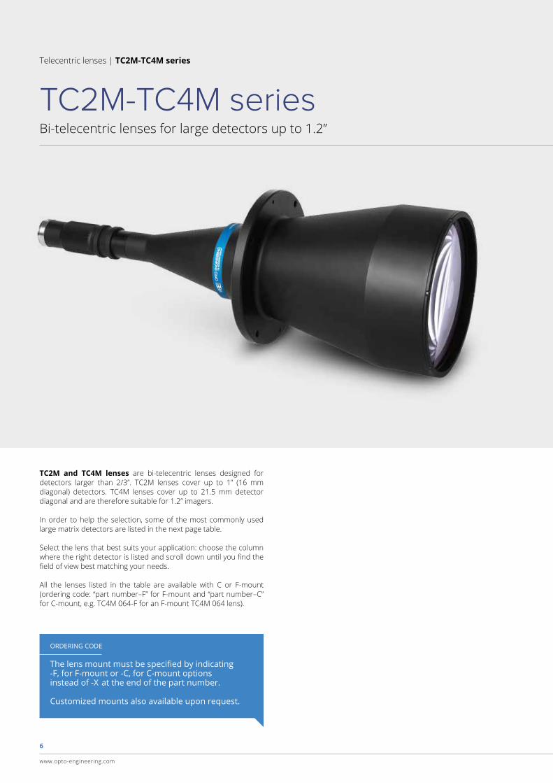
TC2M-TC4M series
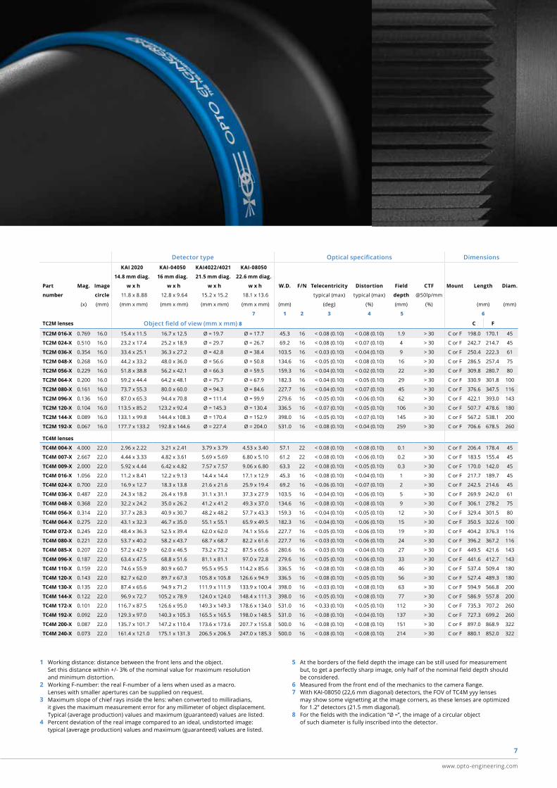
TC2M and TC4M lenses are bi-telecentric lenses designed for detectors larger than 2/3”. TC2M lenses cover up to 1” (16 mm diagonal) detectors. TC4M lenses cover up to 21.5 mm detector diagonal and are therefore suitable for 1.2” imagers.
In order to help the selection, some of the most commonly used large matrix detectors are listed in the next page table.
Select the lens that best suits your application: choose the column where the right detector is listed and scroll down until you find the field of view best matching your needs.
All the lenses listed in the table are available with C or F-mount (ordering code: “part number–F” for F-mount and “part number–C” for C-mount, e.g. TC4M 064-F for an F-mount TC4M 064 lens).
ORDERING CODE
The lens mount must be specified by indicating -F, for F-mount or -C, for C-mount options instead of -X at the end of the part number.
Customized mounts also available upon request.
7
www.opto-engineering.com
1 Working distance: distance between the front lens and the object. Set this distance within +/- 3% of the nominal value for maximum resolution and minimum distortion.2 Working F-number: the real F-number of a lens when used as a macro. Lenses with smaller apertures can be supplied on request.3 Maximum slope of chief rays inside the lens: when converted to milliradians, it gives the maximum measurement error for any millimeter of object displacement. Typical (average production) values and maximum (guaranteed) values are listed.4 Percent deviation of the real image compared to an ideal, undistorted image: typical (average production) values and maximum (guaranteed) values are listed.
5 At the borders of the field depth the image can be still used for measurement but, to get a perfectly sharp image, only half of the nominal field depth should be considered.6 Measured from the front end of the mechanics to the camera flange.7 With KAI-08050 (22,6 mm diagonal) detectors, the FOV of TC4M yyy lenses may show some vignetting at the image corners, as these lenses are optimized for 1.2” detectors (21.5 mm diagonal).8 For the fields with the indication “Ø =”, the image of a circular object of such diameter is fully inscribed into the detector.
Detector type Optical specifications DimensionsKAI 2020 KAI-04050 KAI4022/4021 KAI-08050
14.8 mm diag. 16 mm diag. 21.5 mm diag. 22.6 mm diag.
Part Mag. Image w x h w x h w x h w x h W.D. F/N Telecentricity Distortion Field CTF Mount Length Diam.
number circle 11.8 x 8.88 12.8 x 9.64 15.2 x 15.2 18.1 x 13.6 typical (max) typical (max) depth @50lp/mm
(x) (mm) (mm x mm) (mm x mm) (mm x mm) (mm x mm) (mm) (deg) (%) (mm) (%) (mm) (mm)
7 1 2 3 4 5 6
TC2M lenses Object field of view (mm x mm) 8 C F
TC2M 016-X 0.769 16.0 15.4 x 11.5 16.7 x 12.5 Ø = 19.7 Ø = 17.7 45.3 16 < 0.08 (0.10) < 0.08 (0.10) 1.9 > 30 C or F 198.0 170.1 45
TC2M 024-X 0.510 16.0 23.2 x 17.4 25.2 x 18.9 Ø = 29.7 Ø = 26.7 69.2 16 < 0.08 (0.10) < 0.07 (0.10) 4 > 30 C or F 242.7 214.7 45
TC2M 036-X 0.354 16.0 33.4 x 25.1 36.3 x 27.2 Ø = 42.8 Ø = 38.4 103.5 16 < 0.03 (0.10) < 0.04 (0.10) 9 > 30 C or F 250.4 222.3 61
TC2M 048-X 0.268 16.0 44.2 x 33.2 48.0 x 36.0 Ø = 56.6 Ø = 50.8 134.6 16 < 0.05 (0.10) < 0.08 (0.10) 16 > 30 C or F 286.5 257.4 75
TC2M 056-X 0.229 16.0 51.8 x 38.8 56.2 x 42.1 Ø = 66.3 Ø = 59.5 159.3 16 < 0.04 (0.10) < 0.02 (0.10) 22 > 30 C or F 309.8 280.7 80
TC2M 064-X 0.200 16.0 59.2 x 44.4 64.2 x 48.1 Ø = 75.7 Ø = 67.9 182.3 16 < 0.04 (0.10) < 0.05 (0.10) 29 > 30 C or F 330.9 301.8 100
TC2M 080-X 0.161 16.0 73.7 x 55.3 80.0 x 60.0 Ø = 94.3 Ø = 84.6 227.7 16 < 0.04 (0.10) < 0.07 (0.10) 45 > 30 C or F 376.6 347.5 116
TC2M 096-X 0.136 16.0 87.0 x 65.3 94.4 x 70.8 Ø = 111.4 Ø = 99.9 279.6 16 < 0.05 (0.10) < 0.06 (0.10) 62 > 30 C or F 422.1 393.0 143
TC2M 120-X 0.104 16.0 113.5 x 85.2 123.2 x 92.4 Ø = 145.3 Ø = 130.4 336.5 16 < 0.07 (0.10) < 0.05 (0.10) 106 > 30 C or F 507.7 478.6 180
TC2M 144-X 0.089 16.0 133.1 x 99.8 144.4 x 108.3 Ø = 170.4 Ø = 152.9 398.0 16 < 0.05 (0.10) < 0.07 (0.10) 145 > 30 C or F 567.2 538.1 200
TC2M 192-X 0.067 16.0 177.7 x 133.2 192.8 x 144.6 Ø = 227.4 Ø = 204.0 531.0 16 < 0.08 (0.10) < 0.04 (0.10) 259 > 30 C or F 706.6 678.5 260
TC4M lenses
TC4M 004-X 4.000 22.0 2.96 x 2.22 3.21 x 2.41 3.79 x 3.79 4.53 x 3.40 57.1 22 < 0.08 (0.10) < 0.08 (0.10) 0.1 > 30 C or F 206.4 178.4 45
TC4M 007-X 2.667 22.0 4.44 x 3.33 4.82 x 3.61 5.69 x 5.69 6.80 x 5.10 61.2 22 < 0.08 (0.10) < 0.06 (0.10) 0.2 > 30 C or F 183.5 155.4 45
TC4M 009-X 2.000 22.0 5.92 x 4.44 6.42 x 4.82 7.57 x 7.57 9.06 x 6.80 63.3 22 < 0.08 (0.10) < 0.05 (0.10) 0.3 > 30 C or F 170.0 142.0 45
TC4M 016-X 1.056 22.0 11.2 x 8.41 12.2 x 9.13 14.4 x 14.4 17.1 x 12.9 45.3 16 < 0.08 (0.10) < 0.04 (0.10) 1 > 30 C or F 217.7 189.7 45
TC4M 024-X 0.700 22.0 16.9 x 12.7 18.3 x 13.8 21.6 x 21.6 25.9 x 19.4 69.2 16 < 0.06 (0.10) < 0.07 (0.10) 2 > 30 C or F 242.5 214.6 45
TC4M 036-X 0.487 22.0 24.3 x 18.2 26.4 x 19.8 31.1 x 31.1 37.3 x 27.9 103.5 16 < 0.04 (0.10) < 0.06 (0.10) 5 > 30 C or F 269.9 242.0 61
TC4M 048-X 0.368 22.0 32.2 x 24.2 35.0 x 26.2 41.2 x 41.2 49.3 x 37.0 134.6 16 < 0.08 (0.10) < 0.08 (0.10) 9 > 30 C or F 306.1 278.2 75
TC4M 056-X 0.314 22.0 37.7 x 28.3 40.9 x 30.7 48.2 x 48.2 57.7 x 43.3 159.3 16 < 0.04 (0.10) < 0.05 (0.10) 12 > 30 C or F 329.4 301.5 80
TC4M 064-X 0.275 22.0 43.1 x 32.3 46.7 x 35.0 55.1 x 55.1 65.9 x 49.5 182.3 16 < 0.04 (0.10) < 0.06 (0.10) 15 > 30 C or F 350.5 322.6 100
TC4M 072-X 0.245 22.0 48.4 x 36.3 52.5 x 39.4 62.0 x 62.0 74.1 x 55.6 227.7 16 < 0.05 (0.10) < 0.06 (0.10) 19 > 30 C or F 404.2 376.3 116
TC4M 080-X 0.221 22.0 53.7 x 40.2 58.2 x 43.7 68.7 x 68.7 82.2 x 61.6 227.7 16 < 0.03 (0.10) < 0.06 (0.10) 24 > 30 C or F 396.2 367.2 116
TC4M 085-X 0.207 22.0 57.2 x 42.9 62.0 x 46.5 73.2 x 73.2 87.5 x 65.6 280.6 16 < 0.03 (0.10) < 0.04 (0.10) 27 > 30 C or F 449.5 421.6 143
TC4M 096-X 0.187 22.0 63.4 x 47.5 68.8 x 51.6 81.1 x 81.1 97.0 x 72.8 279.6 16 < 0.05 (0.10) < 0.06 (0.10) 33 > 30 C or F 441.6 412.7 143
TC4M 110-X 0.159 22.0 74.6 x 55.9 80.9 x 60.7 95.5 x 95.5 114.2 x 85.6 336.5 16 < 0.08 (0.10) < 0.08 (0.10) 46 > 30 C or F 537.4 509.4 180
TC4M 120-X 0.143 22.0 82.7 x 62.0 89.7 x 67.3 105.8 x 105.8 126.6 x 94.9 336.5 16 < 0.08 (0.10) < 0.05 (0.10) 56 > 30 C or F 527.4 489.3 180
TC4M 130-X 0.135 22.0 87.4 x 65.6 94.9 x 71.2 111.9 x 111.9 133.9 x 100.4 398.0 16 < 0.03 (0.10) < 0.08 (0.10) 63 > 30 C or F 594.9 566.8 200
TC4M 144-X 0.122 22.0 96.9 x 72.7 105.2 x 78.9 124.0 x 124.0 148.4 x 111.3 398.0 16 < 0.05 (0.10) < 0.08 (0.10) 77 > 30 C or F 586.9 557.8 200
TC4M 172-X 0.101 22.0 116.7 x 87.5 126.6 x 95.0 149.3 x 149.3 178.6 x 134.0 531.0 16 < 0.33 (0.10) < 0.05 (0.10) 112 > 30 C or F 735.3 707.2 260
TC4M 192-X 0.092 22.0 129.3 x 97.0 140.3 x 105.3 165.5 x 165.5 198.0 x 148.5 531.0 16 < 0.08 (0.10) < 0.04 (0.10) 137 > 30 C or F 727.3 699.2 260
TC4M 200-X 0.087 22.0 135.7 x 101.7 147.2 x 110.4 173.6 x 173.6 207.7 x 155.8 500.0 16 < 0.08 (0.10) < 0.08 (0.10) 151 > 30 C or F 897.0 868.9 322
TC4M 240-X 0.073 22.0 161.4 x 121.0 175.1 x 131.3 206.5 x 206.5 247.0 x 185.3 500.0 16 < 0.08 (0.10) < 0.08 (0.10) 214 > 30 C or F 880.1 852.0 322
8
www.opto-engineering.com
Telecentric lenses | TC16M series
Bi-telecentric lenses for 35 mm and 4 k / 8 k pixel line detectors
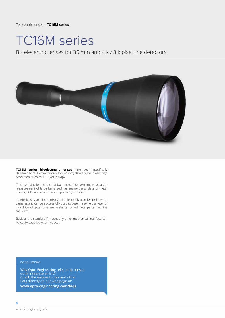
TC16M series
TC16M series bi-telecentric lenses have been specifically designed to fit 35 mm format (36 x 24 mm) detectors with very high resolution, such as 11, 16 or 29 Mpx.
This combination is the typical choice for extremely accurate measurement of large items such as engine parts, glass or metal sheets, PCBs and electronic components, LCDs, etc.
TC16M lenses are also perfectly suitable for 4 kpx and 8 kpx linescan cameras and can be successfully used to determine the diameter of cylindrical objects: for example shafts, turned metal parts, machine tools, etc.
Besides the standard F-mount any other mechanical interface can be easily supplied upon request.
DO YOU KNOW?
Why Opto Engineering telecentric lensesdon’t integrate an iris? Check the answer to this and otherFAQ directly on our web page at:www.opto-engineering.com/faqs
9
www.opto-engineering.com
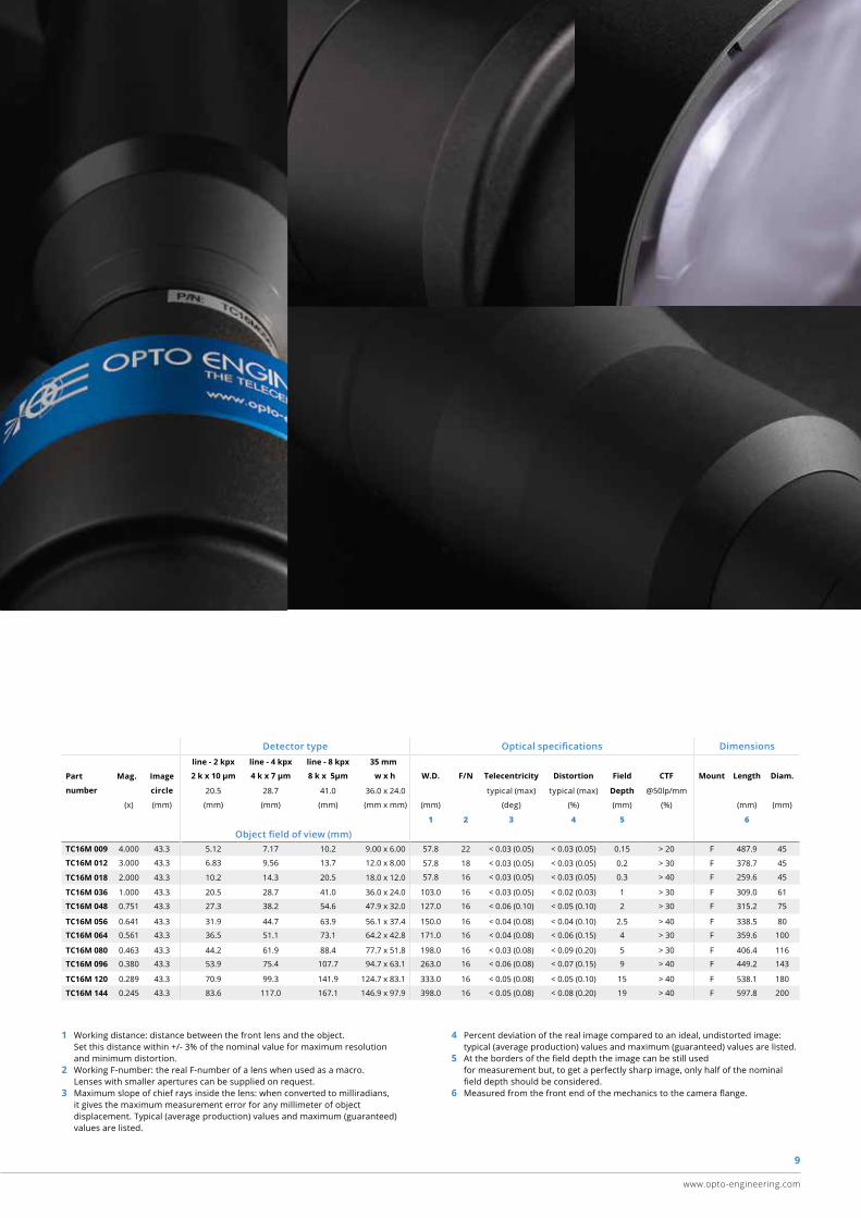
1 Working distance: distance between the front lens and the object. Set this distance within +/- 3% of the nominal value for maximum resolution and minimum distortion.2 Working F-number: the real F-number of a lens when used as a macro. Lenses with smaller apertures can be supplied on request. 3 Maximum slope of chief rays inside the lens: when converted to milliradians, it gives the maximum measurement error for any millimeter of object displacement. Typical (average production) values and maximum (guaranteed) values are listed.
4 Percent deviation of the real image compared to an ideal, undistorted image: typical (average production) values and maximum (guaranteed) values are listed.5 At the borders of the field depth the image can be still used for measurement but, to get a perfectly sharp image, only half of the nominal field depth should be considered.6 Measured from the front end of the mechanics to the camera flange.
Detector type Optical specifications Dimensions line - 2 kpx line - 4 kpx line - 8 kpx 35 mm
Part Mag. Image 2 k x 10 μm 4 k x 7 μm 8 k x 5μm w x h W.D. F/N Telecentricity Distortion Field CTF Mount Length Diam.
number circle 20.5 28.7 41.0 36.0 x 24.0 typical (max) typical (max) Depth @50lp/mm
(x) (mm) (mm) (mm) (mm) (mm x mm) (mm) (deg) (%) (mm) (%) (mm) (mm)
1 2 3 4 5 6
Object field of view (mm)TC16M 009 4.000 43.3 5.12 7.17 10.2 9.00 x 6.00 57.8 22 < 0.03 (0.05) < 0.03 (0.05) 0.15 > 20 F 487.9 45
TC16M 012 3.000 43.3 6.83 9.56 13.7 12.0 x 8.00 57.8 18 < 0.03 (0.05) < 0.03 (0.05) 0.2 > 30 F 378.7 45
TC16M 018 2.000 43.3 10.2 14.3 20.5 18.0 x 12.0 57.8 16 < 0.03 (0.05) < 0.03 (0.05) 0.3 > 40 F 259.6 45
TC16M 036 1.000 43.3 20.5 28.7 41.0 36.0 x 24.0 103.0 16 < 0.03 (0.05) < 0.02 (0.03) 1 > 30 F 309.0 61
TC16M 048 0.751 43.3 27.3 38.2 54.6 47.9 x 32.0 127.0 16 < 0.06 (0.10) < 0.05 (0.10) 2 > 30 F 315.2 75
TC16M 056 0.641 43.3 31.9 44.7 63.9 56.1 x 37.4 150.0 16 < 0.04 (0.08) < 0.04 (0.10) 2.5 > 40 F 338.5 80
TC16M 064 0.561 43.3 36.5 51.1 73.1 64.2 x 42.8 171.0 16 < 0.04 (0.08) < 0.06 (0.15) 4 > 30 F 359.6 100
TC16M 080 0.463 43.3 44.2 61.9 88.4 77.7 x 51.8 198.0 16 < 0.03 (0.08) < 0.09 (0.20) 5 > 30 F 406.4 116
TC16M 096 0.380 43.3 53.9 75.4 107.7 94.7 x 63.1 263.0 16 < 0.06 (0.08) < 0.07 (0.15) 9 > 40 F 449.2 143
TC16M 120 0.289 43.3 70.9 99.3 141.9 124.7 x 83.1 333.0 16 < 0.05 (0.08) < 0.05 (0.10) 15 > 40 F 538.1 180
TC16M 144 0.245 43.3 83.6 117.0 167.1 146.9 x 97.9 398.0 16 < 0.05 (0.08) < 0.08 (0.20) 19 > 40 F 597.8 200
10
www.opto-engineering.com
Telecentric lenses | TC12K series
Telecentric lenses for 12 k and 16 k pixel linescan cameras
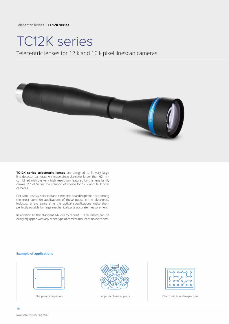
TC12K series
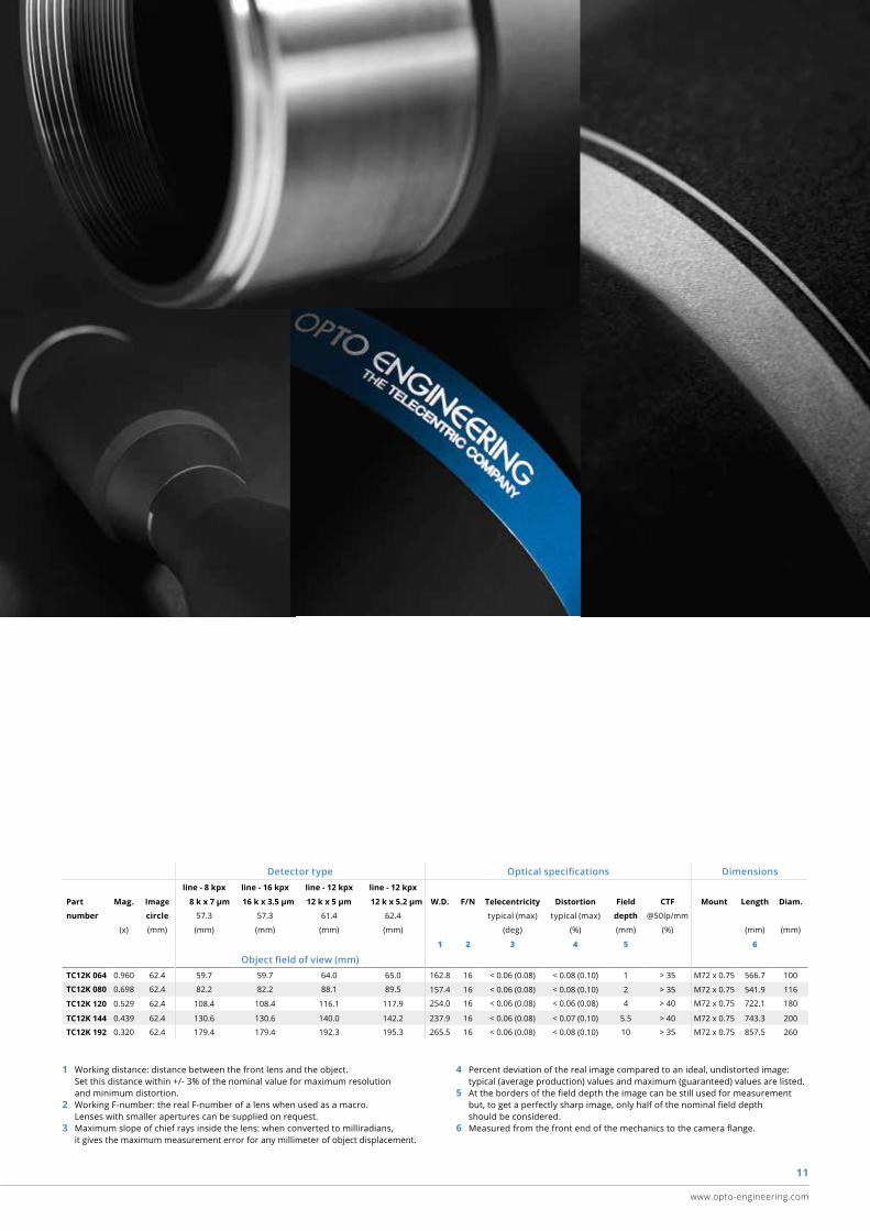
TC12K series telecentric lenses are designed to fit very large line detector cameras. An image circle diameter larger than 62 mm combined with the very high resolution featured by this lens family makes TC12K Series the solution of choice for 12 k and 16 k pixel cameras.
Flat panel display, solar cell and electronic board inspection are among the most common applications of these optics in the electronics industry; at the same time the optical specifications make them perfectly suitable for large mechanical parts accurate measurement.
In addition to the standard M72x0.75 mount TC12K lenses can be easily equipped with any other type of camera mount at no extra cost.
Flat panel inspection Large mechanical parts Electronic board inspection
Example of applications
11
www.opto-engineering.com
1 Working distance: distance between the front lens and the object. Set this distance within +/- 3% of the nominal value for maximum resolution and minimum distortion.2 Working F-number: the real F-number of a lens when used as a macro. Lenses with smaller apertures can be supplied on request. 3 Maximum slope of chief rays inside the lens: when converted to milliradians, it gives the maximum measurement error for any millimeter of object displacement.
4 Percent deviation of the real image compared to an ideal, undistorted image: typical (average production) values and maximum (guaranteed) values are listed.5 At the borders of the field depth the image can be still used for measurement but, to get a perfectly sharp image, only half of the nominal field depth should be considered.6 Measured from the front end of the mechanics to the camera flange.
Detector type Optical specifications Dimensions line - 8 kpx line - 16 kpx line - 12 kpx line - 12 kpx
Part Mag. Image 8 k x 7 μm 16 k x 3.5 μm 12 k x 5 μm 12 k x 5.2 μm W.D. F/N Telecentricity Distortion Field CTF Mount Length Diam.
number circle 57.3 57.3 61.4 62.4 typical (max) typical (max) depth @50lp/mm
(x) (mm) (mm) (mm) (mm) (mm) (deg) (%) (mm) (%) (mm) (mm)
1 2 3 4 5 6
Object field of view (mm)TC12K 064 0.960 62.4 59.7 59.7 64.0 65.0 162.8 16 < 0.06 (0.08) < 0.08 (0.10) 1 > 35 M72 x 0.75 566.7 100
TC12K 080 0.698 62.4 82.2 82.2 88.1 89.5 157.4 16 < 0.06 (0.08) < 0.08 (0.10) 2 > 35 M72 x 0.75 541.9 116
TC12K 120 0.529 62.4 108.4 108.4 116.1 117.9 254.0 16 < 0.06 (0.08) < 0.06 (0.08) 4 > 40 M72 x 0.75 722.1 180
TC12K 144 0.439 62.4 130.6 130.6 140.0 142.2 237.9 16 < 0.06 (0.08) < 0.07 (0.10) 5.5 > 40 M72 x 0.75 743.3 200
TC12K 192 0.320 62.4 179.4 179.4 192.3 195.3 265.5 16 < 0.06 (0.08) < 0.08 (0.10) 10 > 35 M72 x 0.75 857.5 260
12
www.opto-engineering.com
Telecentric lenses | LTCL series
Collimated (telecentric) LED illuminators
LTCL series
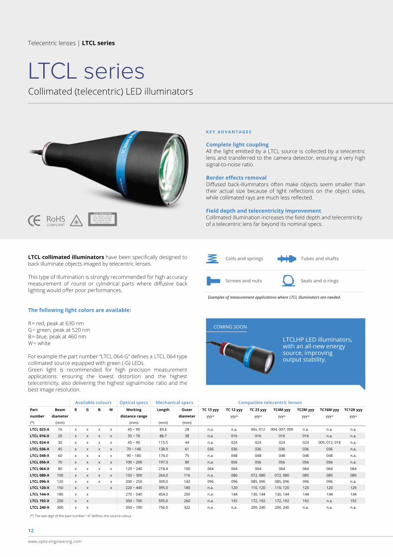
LTCL collimated illuminators have been specifically designed to back illuminate objects imaged by telecentric lenses.
This type of illumination is strongly recommended for high accuracy measurement of round or cylindrical parts where diffusive back lighting would offer poor performances.
Examples of measurement applications where LTCL illuminators are needed.
Coils and springs
Screws and nuts
Tubes and shafts
Seals and o-rings
K E Y A D V A N T A G E S
(*) The last digit of the part number “-X” defines the source colour.
Available colours Optical specs Mechanical specs Compatible telecentric lensesPart Beam R G B W Working Length Outer TC 13 yyy TC 12 yyy TC 23 yyy TC4M yyy TC2M yyy TC16M yyy TC12K yyy
number diameter distance range diameter yyy= yyy= yyy= yyy= yyy= yyy= yyy=
(*) (mm) (mm) (mm) (mm)
LTCL 023-X 16 x x x x 45 ~ 90 83.6 28 n.a. n.a. 00x, 012 004, 007, 009 n.a. n.a. n.a.
LTCL 016-X 20 x x x x 35 ~ 70 86.7 38 n.a. 016 016 016 016 n.a. n.a.
LTCL 024-X 30 x x x x 45 ~ 90 115.5 44 n.a. 024 024 024 024 009, 012, 018 n.a.
LTCL 036-X 45 x x x x 70 ~ 140 138.9 61 036 036 036 036 036 036 n.a.
LTCL 048-X 60 x x x x 90 ~ 180 174.0 75 n.a. 048 048 048 048 048 n.a.
LTCL 056-X 70 x x x x 100 ~ 200 197.3 80 n.a. 056 056 056 056 056 n.a.
LTCL 064-X 80 x x x x 120 ~ 240 218.4 100 064 064 064 064 064 064 064
LTCL 080-X 100 x x x x 150 ~ 300 264.0 116 n.a. 080 072, 080 072, 080 080 080 080
LTCL 096-X 120 x x x x 200 ~ 250 309,0 143 096 096 085, 096 085, 096 096 096 n.a.
LTCL 120-X 150 x x x 220 ~ 440 395.0 180 n.a. 120 110, 120 110, 120 120 120 120
LTCL 144-X 180 x x 270 ~ 540 454.0 200 n.a. 144 130, 144 130, 144 144 144 144
LTCL 192-X 250 x x 350 ~ 700 595.0 260 n.a. 192 172, 192 172, 192 192 n.a. 192
LTCL 240-X 300 x x 350 ~ 700 756.0 322 n.a. n.a. 200, 240 200, 240 n.a. n.a. n.a.
Complete light couplingAll the light emitted by a LTCL source is collected by a telecentric lens and transferred to the camera detector, ensuring a very high signal-to-noise ratio.
Border effects removalDiffused back-illuminators often make objects seem smaller than their actual size because of light reflections on the object sides, while collimated rays are much less reflected.
Field depth and telecentricity improvementCollimated illumination increases the field depth and telecentricityof a telecentric lens far beyond its nominal specs.
The following light colors are available:
R= red, peak at 630 nmG= green, peak at 520 nmB= blue, peak at 460 nmW= white
For example the part number “LTCL 064-G” defines a LTCL 064 type collimated source equipped with green (-G) LEDs.Green light is recommended for high precision measurement applications: ensuring the lowest distortion and the highest telecentricity, also delivering the highest signal/noise ratio and the best image resolution.
COMING SOON
LTCLHP LED illuminators, with an all-new energy source, improving output stability.
13
www.opto-engineering.com
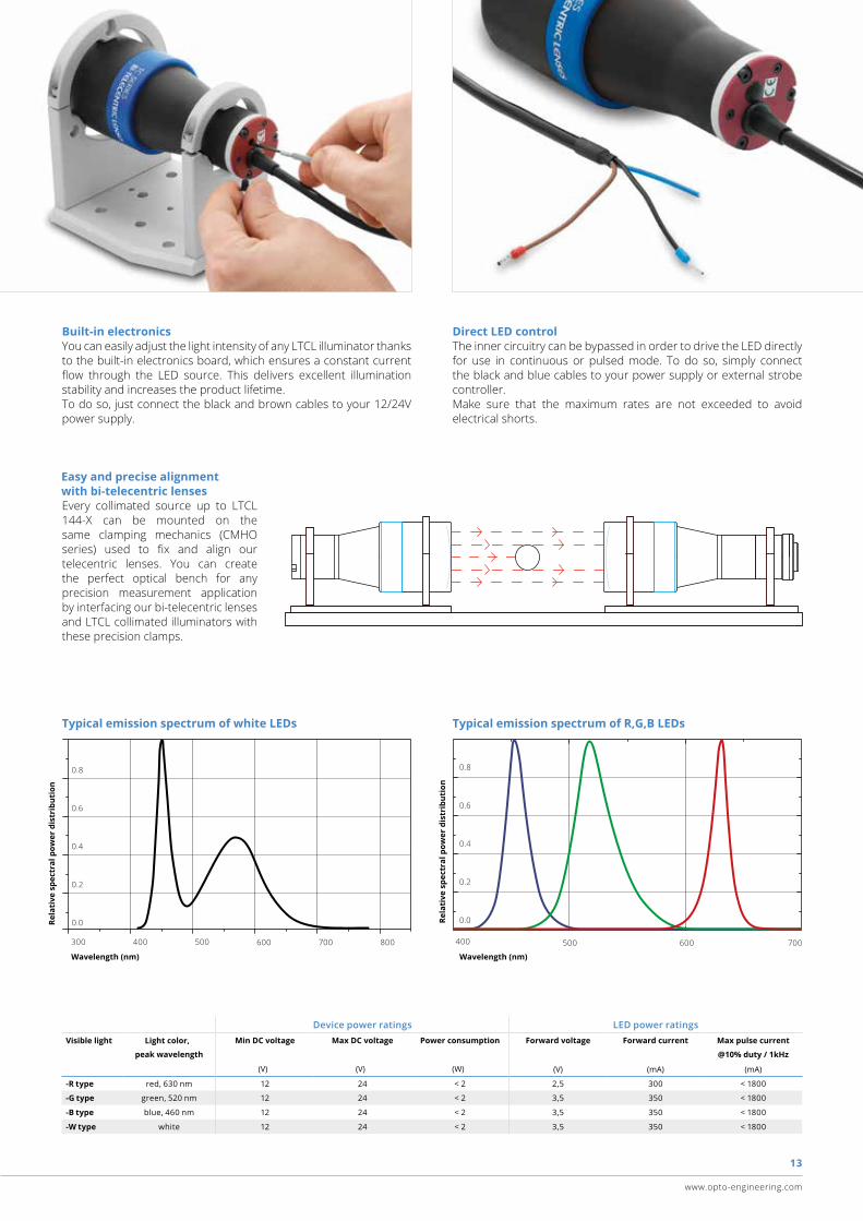
Typical emission spectrum of white LEDs
Wavelength (nm)
Rela
tive
spe
ctra
l pow
er d
istr
ibut
ion
Typical emission spectrum of R,G,B LEDs
Rela
tive
spe
ctra
l pow
er d
istr
ibut
ion
Wavelength (nm)
0.0
0.6
0.8
0.4
0.2
Device power ratings LED power ratingsVisible light Light color, Min DC voltage Max DC voltage Power consumption Forward voltage Forward current Max pulse current
peak wavelength @10% duty / 1kHz
(V) (V) (W) (V) (mA) (mA)
-R type red, 630 nm 12 24 < 2 2,5 300 < 1800
-G type green, 520 nm 12 24 < 2 3,5 350 < 1800
-B type blue, 460 nm 12 24 < 2 3,5 350 < 1800
-W type white 12 24 < 2 3,5 350 < 1800
Built-in electronics You can easily adjust the light intensity of any LTCL illuminator thanks to the built-in electronics board, which ensures a constant current flow through the LED source. This delivers excellent illumination stability and increases the product lifetime. To do so, just connect the black and brown cables to your 12/24V power supply.
Direct LED control The inner circuitry can be bypassed in order to drive the LED directly for use in continuous or pulsed mode. To do so, simply connect the black and blue cables to your power supply or external strobe controller. Make sure that the maximum rates are not exceeded to avoid electrical shorts.
Every collimated source up to LTCL 144-X can be mounted on the same clamping mechanics (CMHO series) used to fix and align our telecentric lenses. You can create the perfect optical bench for any precision measurement application by interfacing our bi-telecentric lenses and LTCL collimated illuminators with these precision clamps.
Easy and precise alignment with bi-telecentric lenses
400 500 600 700300
0.6
0.8
0.4
0.2
0.0
400 500 600 700 800
14
www.opto-engineering.com
TC optical bench kits for easy measurements
TCBENCH series
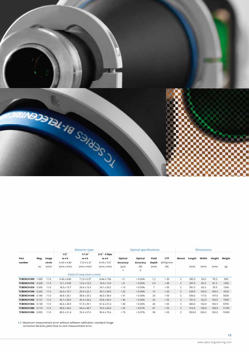
Telecentric lenses | TCBENCH series
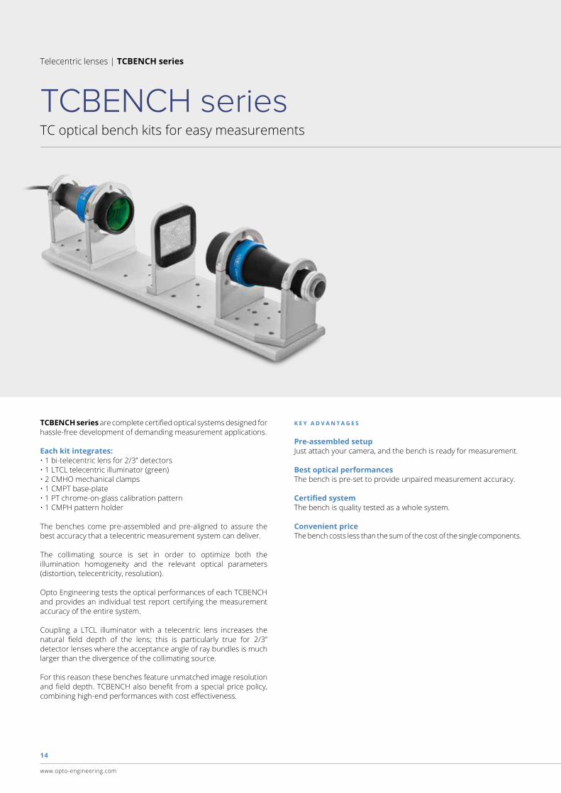
TCBENCH series are complete certified optical systems designed for hassle-free development of demanding measurement applications.
Each kit integrates:• 1 bi-telecentric lens for 2/3” detectors• 1 LTCL telecentric illuminator (green)• 2 CMHO mechanical clamps • 1 CMPT base-plate• 1 PT chrome-on-glass calibration pattern• 1 CMPH pattern holder
The benches come pre-assembled and pre-aligned to assure the best accuracy that a telecentric measurement system can deliver.
The collimating source is set in order to optimize both the illumination homogeneity and the relevant optical parameters (distortion, telecentricity, resolution).
Opto Engineering tests the optical performances of each TCBENCH and provides an individual test report certifying the measurement accuracy of the entire system.
Coupling a LTCL illuminator with a telecentric lens increases the natural field depth of the lens; this is particularly true for 2/3” detector lenses where the acceptance angle of ray bundles is much larger than the divergence of the collimating source.
For this reason these benches feature unmatched image resolution and field depth. TCBENCH also benefit from a special price policy, combining high-end performances with cost effectiveness.
K E Y A D V A N T A G E S
Pre-assembled setupJust attach your camera, and the bench is ready for measurement.
Best optical performancesThe bench is pre-set to provide unpaired measurement accuracy.
Certified systemThe bench is quality tested as a whole system.
Convenient priceThe bench costs less than the sum of the cost of the single components.
15
www.opto-engineering.com
1,2 Maximum measurement error without software calibration; standard image correction libraries yield close to zero measurement error.
Detector type Optical specifications Dimensions 1/2’’ 1/1.8’’ 2/3’’ - 5 Mpx
Part Mag. Image w x h w x h w x h Optical Optical Field CTF Mount Length Width Height Weight
number circle 6.40 x 4.80 7.13 x 5.37 8.45 x 7.07 Accuracy Accuracy Depth @70lp/mm
(x) (mm) (mm x mm) (mm x mm) (mm x mm) (μm) (%) (mm) (%) (mm) (mm) (mm) (g)
1 2
Field of view (mm x mm)TCBENCH 009 1.000 11.0 6.40 x 4.80 7.13 x 5.37 8.44 x 7.06 < 5 < 0.06% 1.2 > 35 C 282.0 56.0 78.5 900
TCBENCH 016 0.528 11.0 12.1 x 9.09 13.5 x 10.2 16.0 x 13.4 < 8 < 0.05% 2.9 > 40 C 297.0 65.5 81.2 1200
TCBENCH 024 0.350 11.0 18.3 x 13.7 20.4 x 15.3 24.1 x 20.2 < 13 < 0.05% 7 > 55 C 391.0 65.5 78.5 1340
TCBENCH 036 0.243 11.0 26.3 x 19.7 29.3 x 22.1 34.7 x 29.0 < 22 < 0.06% 14 > 50 C 529.0 103.0 140.5 4150
TCBENCH 048 0.184 11.0 34.8 x 26.1 38.8 x 29.2 46.0 x 38.4 < 31 < 0.06% 24 > 50 C 636.0 117.0 147.5 5600
TCBENCH 056 0.157 11.0 40.7 x 30.6 45.4 x 34.2 53.8 x 45.0 < 36 < 0.06% 33 > 55 C 701.0 122.0 150.0 7300
TCBENCH 064 0.138 11.0 46.6 x 34.9 51.9 x 39.1 61.4 x 51.4 < 40 < 0.06% 43 > 65 C 845.0 143.0 160.5 8700
TCBENCH 080 0.110 11.0 58.0 x 43.5 64.6 x 48.7 76.5 x 64.0 < 55 < 0.07% 67 > 55 C 915.0 158.0 168.0 11100
TCBENCH 096 0.093 11.0 68.5 x 51.4 76.3 x 57.5 90.4 x 75.6 < 70 < 0.07% 94 > 50 C 1053.0 206.5 185.0 15300

Contact us
www.opto-engineering.com
EUROPE UNITED STATES
ASIA
Opto EngineeringChinaRoom 2405, n°885, Renmin RDHuangpu District 200010Shanghai, Chinaphone: +86 21 [email protected]
Opto [email protected]
Opto [email protected]
Opto EngineeringGermanyAgnes-Pockels-Bogen, 180992 München, DEphone: +49 0 89 [email protected]
Opto EngineeringUSA11261 Richmond AveSte G-108 - Houston, TX 77082phone: +1 832 [email protected]
Opto EngineeringEurope headquartersCirconvallazione Sud, 1546100 Mantova, ITphone: +39 0376 [email protected]