Embed Size (px)
Citation preview
1
2005/03/11(C) Herbert Haas
Telco Scalable Backbones
PDH, SONET/SDH

2
�Everything
that can be invented
has been invented�
Charles H. Duell,
commissioner of the
US Office of Patents 1899
3
3(C) Herbert Haas 2005/03/11
Agenda
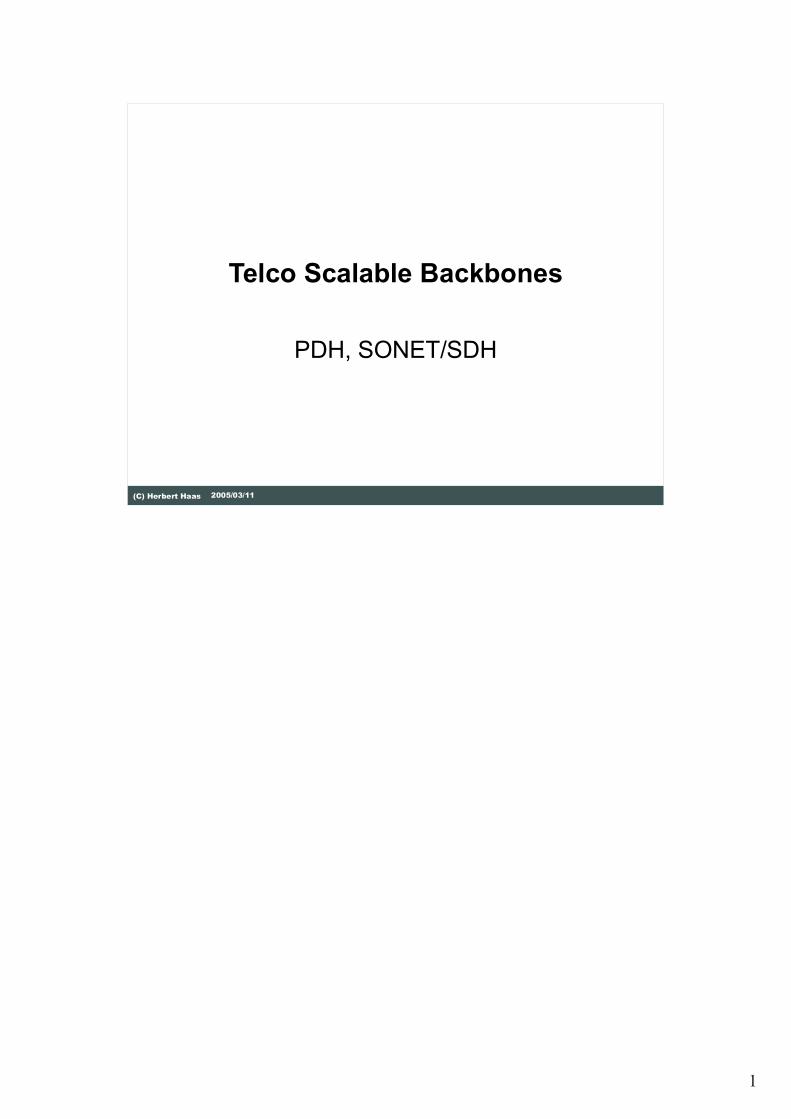
� Basics
�Shannon
� Jitter
�Compounding laws
�Digital Hierarchies
� PDH
� SONET/SDH
This chapter gives an introduction into the complex world of Telco technologies.
First we discuss transmission basics related to voice and scalability issues.
In order to understand these technologies it is important to know about Shannon's
laws, jitter problems, signal to noise problems, and digital hierarchy concepts.
After this basics sections this chapter presents two important Telco backbone
technologies, PDH and SONET/SDH.

4
4(C) Herbert Haas 2005/03/11
Long History
� Origins in late 19th century
� Voice was/is the yardstick
� Same terms
� Same signaling principles
� Even today, although data traffic
increases dramatically
� Led to technological constraints and
demands
"circuit" "cross-
connect"
Telco technologies have a long history. Its origins date back until the late 19th
century. Originally voice transmission was the only goal. Even today the
characteristics of voice transmission forms the basic design of Telco technologies
such as PDH and SONET/SDH.
5
5(C) Herbert Haas 2005/03/11
General Goals
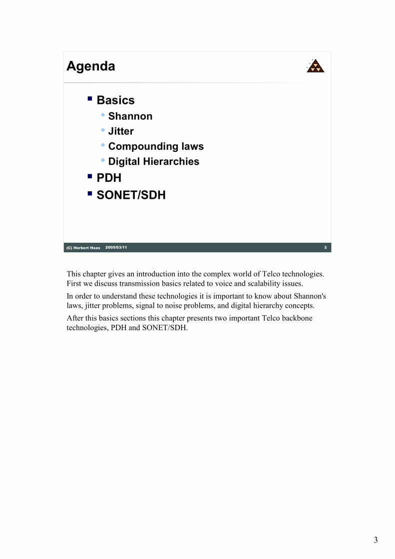
� Interoperability
�Over decades
�Over different vendors
�World-wide!
� Availability
�Protection lines in case of failures
�High non-blocking probability
The most important goals for Telco technologies are interoperability and
availability.
Telco backbones are laid throughout nations and must therefore function over
several decades, must integrate with older technologies and different vendors.
Actually, people expect to communicate from any phone on earth to any other
phone on earth.
Due to the big size of these networks even a small error probability can cause a
denial of service for thousands or even millions of users. Because of this the
Telco backbones must be designed to support great availability, for example using
redundant protection lines which are activated in case of failures.
Additionally it cannot be economically justified to dimension a backbone
connection which could support all possible users at the same time, for instance
between two cities. Therefore the user behaviors must be estimated and complex
statistical calculations are made in order to dimension the link.
6
6(C) Herbert Haas 2005/03/11
Sampling of Voice
� Shannon's Theorem
� Any analogue signal with limited bandwidth fB can be
sampled and reconstructed properly when the
sampling frequency is 2fB
� Speech signal has most of its power and information
between 0 and 4000 Hz
Power
Frequency300 Hz 3400 Hz
Telephone channel: 300-3400 Hz
8000 Hz x 8 bit resolution = 64 kbit/s
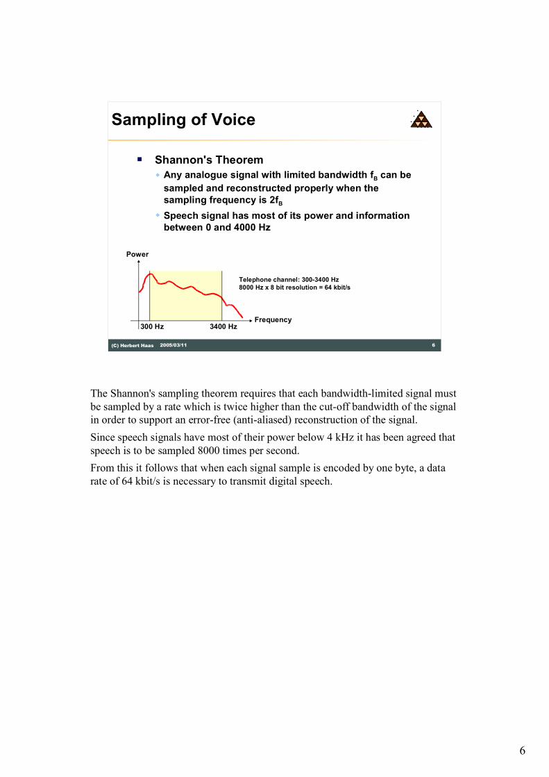
The Shannon's sampling theorem requires that each bandwidth-limited signal must
be sampled by a rate which is twice higher than the cut-off bandwidth of the signal
in order to support an error-free (anti-aliased) reconstruction of the signal.
Since speech signals have most of their power below 4 kHz it has been agreed that
speech is to be sampled 8000 times per second.
From this it follows that when each signal sample is encoded by one byte, a data
rate of 64 kbit/s is necessary to transmit digital speech.

7
7(C) Herbert Haas 2005/03/11
Isochronous Traffic
� Data rate end-to-end must be
constant
� Delay variation (jitter) is critical
� To enable echo suppression
� To reconstruct sampled analog signals
without otherwise distortion
Next, it is important to understand the properties of isochronous traffic. "Iso"
means "Equal" and "chronous" means "time". That is, each portion of data of an
isochronous traffic must be delivered exactly with same delay.
Delay variations�also called "jitter"�are very critical for isochronous traffic. For
example telephony requires isochronous transmission because of the bidirectional
communication, echo suppression is necessary. But how to suppress echoes when
they arrive at different times?
8
8(C) Herbert Haas 2005/03/11
Realtime Traffic
� Requires guaranteed bounded delay
"only"
� Example:
� Telephony (< 1s RTT)
� Interactive traffic (remote operations)
�Remote control
� Telemetry
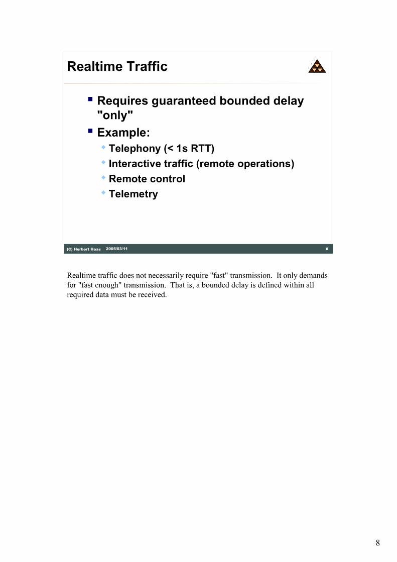
Realtime traffic does not necessarily require "fast" transmission. It only demands
for "fast enough" transmission. That is, a bounded delay is defined within all
required data must be received.
9
9(C) Herbert Haas 2005/03/11
Solutions
� Isochronous network � Common clock for all components
� Aka "Synchronous" network
� Plesiochronous network� With end-to-end synchronization
somehow
� Totally asynchronous network � Using buffers (playback) and QoS
techniques
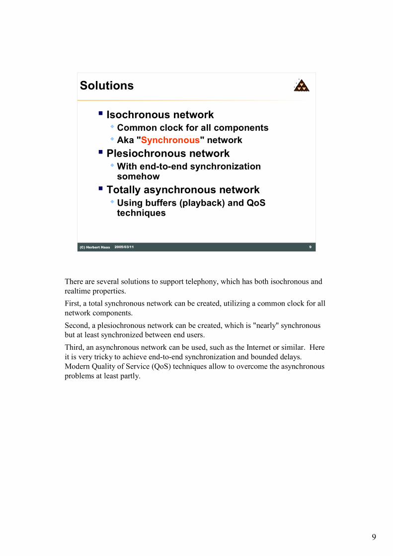
There are several solutions to support telephony, which has both isochronous and
realtime properties.
First, a total synchronous network can be created, utilizing a common clock for all
network components.
Second, a plesiochronous network can be created, which is "nearly" synchronous
but at least synchronized between end users.
Third, an asynchronous network can be used, such as the Internet or similar. Here
it is very tricky to achieve end-to-end synchronization and bounded delays.
Modern Quality of Service (QoS) techniques allow to overcome the asynchronous
problems at least partly.

10
10(C) Herbert Haas 2005/03/11
Improving SNR
� SNR improvement of speech signals� Quantize loud signals much coarser than quiet signals
� Expansion and compression specified by nonlinear function� USA: m-law (Bell)
� Europe: A-law (CCITT)
Quantization
levels
Analogue input signal
Conversion is task
of the m-law world
The Signal-to-Noise Ratio (SNR) is an indicator of signal quality. Furthermore, a
better SNR allows lower signal strengths and higher data rates.
Digital voice is generally "compounded", that is the higher amplitude levels are
quantized at a lower resolution and the smaller amplitudes at a higher quantization
resolution. The characteristic of this compression and expansion technique is
expressed by a nonlinear function which has first been defined by Graham Bell. In
the USA the so-called m-law is used while in Europe the CCITT defined the A-law
function to improve the SNR.
Note that digital voice signals have to be converted when the m-law world talks to
the A-law world or vice versa. The rule is, that the conversion must be a task of
the m-law world.

11
11(C) Herbert Haas 2005/03/11
Plesiochronous Digital Hierarchy
� Created in the 1960s as successor of analog telephony infrastructure
� Smooth migration� Adaptation of analog signaling methods
� Based on Synchronous TDM
� Still important today� Telephony access level
� ISDN PRI
� Leased line
In the middle of the 20th century, the telephony network infrastructure was still
analog and very complex. Each connection was realized by a dedicated bundle of
wires and all terminated in the central office. Signaling was slow and primitive
and switching a time consuming process. Furthermore speech quality degraded on
long haul connections.
In the 1960s digital backbones were created and also digital signaling protocols
such has SS#7. Central office equipment became smaller and more efficient and
the number of wires were reduced drastically. This technology was called
Plesiochronous Digital Hierarchy (PDH) and is based on synchronous TDM,
however it was not fully synchronous because of technical restrictions of that days.
PDH is still important and used today.
12
12(C) Herbert Haas 2005/03/11
Why Plesiochronous?
� 1960s technology: No buffering of frames
at high speeds possible
� Goal: Fast delivery, very short delays
(voice!)
� Immediate forwarding of bits
� Pulse stuffing instead of buffering
� Plesiochronous = "nearly synchronous"
� Network is not synchronized but fast
� Sufficient to synchronize sender and receiver
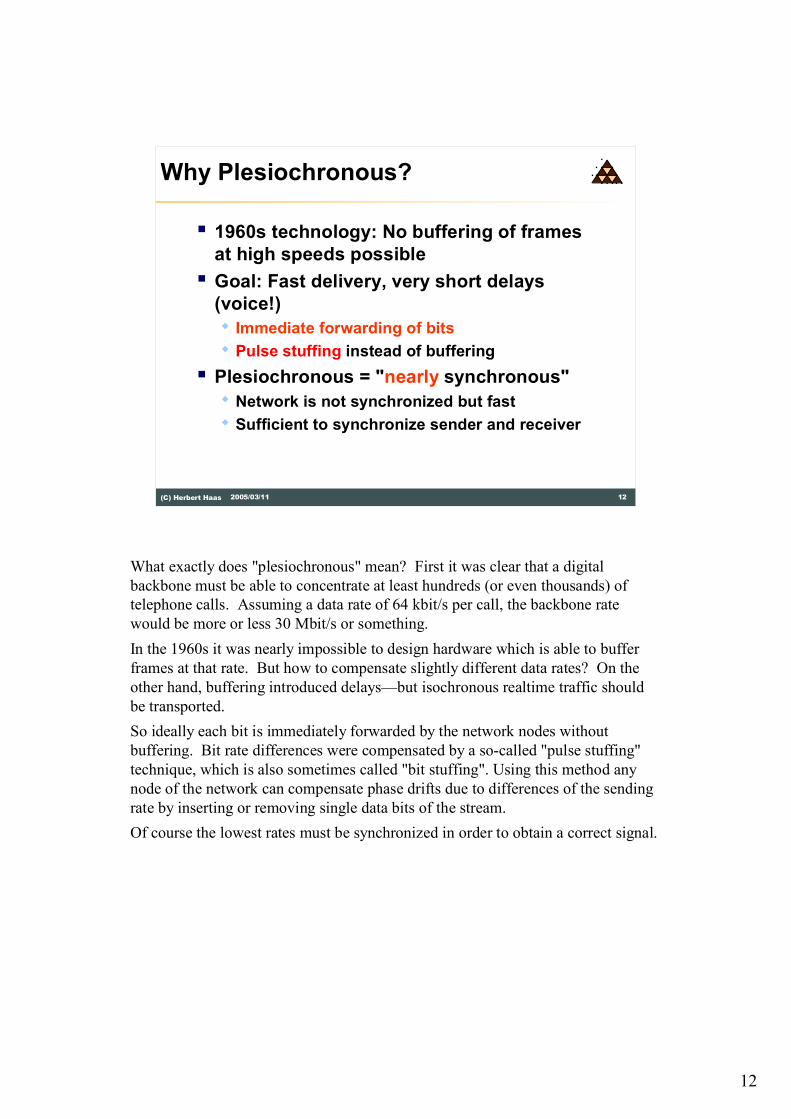
What exactly does "plesiochronous" mean? First it was clear that a digital
backbone must be able to concentrate at least hundreds (or even thousands) of
telephone calls. Assuming a data rate of 64 kbit/s per call, the backbone rate
would be more or less 30 Mbit/s or something.
In the 1960s it was nearly impossible to design hardware which is able to buffer
frames at that rate. But how to compensate slightly different data rates? On the
other hand, buffering introduced delays�but isochronous realtime traffic should
be transported.
So ideally each bit is immediately forwarded by the network nodes without
buffering. Bit rate differences were compensated by a so-called "pulse stuffing"
technique, which is also sometimes called "bit stuffing". Using this method any
node of the network can compensate phase drifts due to differences of the sending
rate by inserting or removing single data bits of the stream.
Of course the lowest rates must be synchronized in order to obtain a correct signal.

13
13(C) Herbert Haas 2005/03/11
Why Hierarchy?
� Only a hierarchical digital multiplexing
infrastructure
� Can connect millions of (low speed)
customers across the city/country/world
� Local infrastructure: Simple star
� Wide area infrastructure: Point-to-point
trunks or ring topologies
� Grooming required
Now we know the meaning of the term "plesiochronous". But what is meant by
the term "hierarchy" in this context? Obviously Telcos were supposed to supply
millions of users with a dial tone. Which topology would be most efficient? Only
star topology can efficiently cover whole villages, cities, and even countries. A
star consists of many point-to-point connections: each spoke is connected to a hub.
The hub is called the "Central Office" (CO) and the spokes are either telephones
or multiplexers.
Traffic always concentrates to the hubs but is also distributed from the hubs. The
hubs are interconnected by PDH trunks. Many trunks constitute spokes and are
again concentrated in another�higher level�hub. This principle is applied
recursively, forming a so-called Digital Hierarchy. If you go deeper into this
hierarchy you will see higher data rates.
The backbone itself consists of point-to-point or ring topologies. Rings have the
advantage of providing one redundant connection between each two nodes.
Of course the number of links are much lower in the heart of the hierarchy
(therefore the data rate is much higher). Hubs are responsible to collect all user
signals that are destined to the same direction and put them onto the same trunk.
This process is called "grooming".
14
14(C) Herbert Haas 2005/03/11
Digital Hierarchy of Multiplexers
.
.
.
.
.
.
.
.
.
.
.
.
.
.
.
E1 = 30 x 64 kbit/s + Overhead
E2 = 4 x 30 x 64 kbit/s + O
E3 = 4 x 4 x 30 x 64 kbit/s + O
E4 = 4 x 4 x 4 x 30
x 64 kbit/s + O
64 kbit/s
Example: European PDH
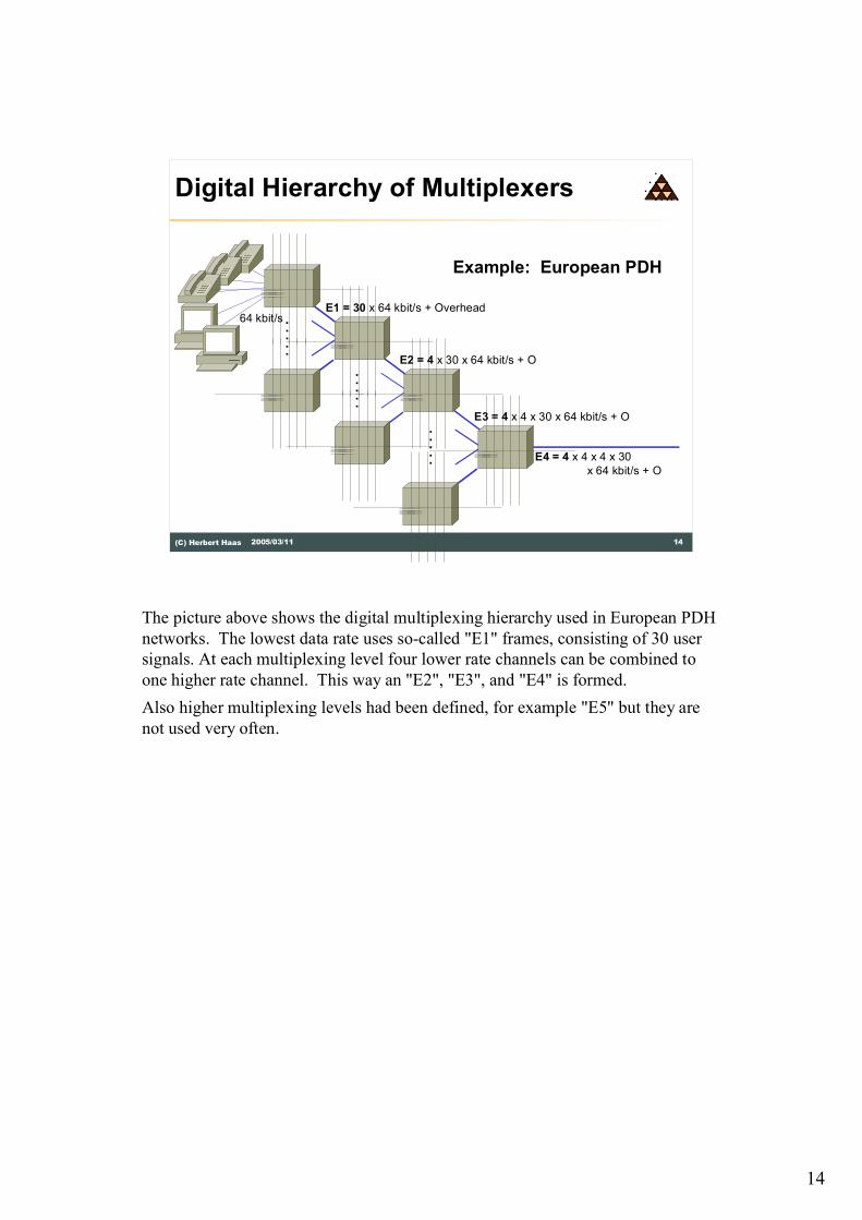
The picture above shows the digital multiplexing hierarchy used in European PDH
networks. The lowest data rate uses so-called "E1" frames, consisting of 30 user
signals. At each multiplexing level four lower rate channels can be combined to
one higher rate channel. This way an "E2", "E3", and "E4" is formed.
Also higher multiplexing levels had been defined, for example "E5" but they are
not used very often.

15
15(C) Herbert Haas 2005/03/11
Digital Signal Levels
� Differentiate:� Signal (Framing layer)
� Carrier (Physical Layer)
� North America (ANSI)� DS-n = Digital Signal level n
� Carrier system: T1, T2, ...
� Europe (CEPT)� CEPT-n = ITU-T digital signal level n
� Carrier system: E1, E2, ...
The Telco world differentiates between the digital signal level and the carrier
system. The signal level can be regarded as the OSI link layer and the carrier
system is similar to the OSI physical layer. Note that this picture is not really
correct because the OSI system cannot really applied to this world.
In North America the ANSI is responsible for Telco standardization efforts and
defined the so-called Digital Signal DS to identify the framing layer. For example
DS-0 is the 64 kbit/s user signal and DS-1 denotes the first multiplexing level.
Equivalently the carrier system for DS-1 is called T1, and DS-2 is carried upon T2,
and so on.
The same thing happened in Europe. The Conference of European Post and
Telecommunications (CEPT, now ETSI) defined signal levels CEPT-1, CEPT-2,
and so on, to be carried upon E1, E2, etcetera.
16
16(C) Herbert Haas 2005/03/11
Worldwide Digital Signal Levels
Signal Carrier
DS0
DS1
DS2
DS3
T1
T2
T3
North AmericaMbit/s
0.064
1.544
6.312
44.736
DS1C T1C 3.152
Signal Carrier
DS0
CEPT-1
CEPT-3
CEPT-4
"E0"
E1
E2
E3
E4
EuropeMbit/s
0.064
2.048
34.368
139.264
CEPT-2 8.448
Channels Channels
1
24
48
96
672
1
32
128
512
2048
DS4 T4 274.1764032 CEPT-5 E5 565.1488192
� Incompatible MUX rates
� Different signalling schemes
� Different overhead
� m-law versus A-law
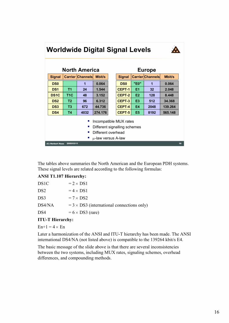
The tables above summaries the North American and the European PDH systems.
These signal levels are related according to the following formulas:
ANSI T1.107 Hierarchy:
DS1C = 2 ´ DS1
DS2 = 4 ´ DS1
DS3 = 7 ´ DS2
DS4/NA = 3 ´ DS3 (international connections only)
DS4 = 6 ´ DS3 (rare)
ITU-T Hierarchy:
En+1 = 4 ´ En
Later a harmonization of the ANSI and ITU-T hierarchy has been made. The ANSI
international DS4/NA (not listed above) is compatible to the 139264 kbit/s E4.
The basic message of the slide above is that there are several inconsistencies
between the two systems, including MUX rates, signaling schemes, overhead
differences, and compounding methods.

17
17(C) Herbert Haas 2005/03/11
Frame Duration
� Each samples (byte) must arrive within 125 ms
� To receive 8000 samples (bytes) per second
� Higher order frames must ensure the same byte-rate per user(!)
DS0: 1 Byte
E1: 32 Byte
E2: 132 Byte
125 ms
64 kbit/s
2.048 kbit/s
8.448 kbit/s
Remember that voice transmission was and is the yardstick for Telco backbone
technologies. Since all higher digital signal levels are basically multiplex methods
to transport many DS0 signals it is clear that each multiplex frame (e.g. an E1
frame or E2 frame etc) must be transmitted within the same time period than the
DS0 signal. A DS0 signal has 64 kbit/s which is created by sending one byte of a
voice sample 8000 times per second.
As it can be seen in the picture above, each user�each DS0�is assigned to one
timeslot in the higher rate frames. Moreover, there is exactly one byte for each
user. Thus, in order to assure a proper delivery of the DS0 signal within a higher
rate frame, any higher rate frame must be sent within 125 ms, which is 1/8000.
We call this a "periodic frame".
18
18(C) Herbert Haas 2005/03/11
Plesiochronous Multiplexing
� Bit interleaving at higher MUX levels � Simpler with slow circuits (Bit stuffing!)
� Complex frame structures and multiplexers (e.g. M12, M13, M14)
� DS1/E1 signals can only be accessed by demultiplexing
� Add-drop multiplexing not possible� All channels must be demultiplexed and then
recombined
� No ring structures, only point-to-point
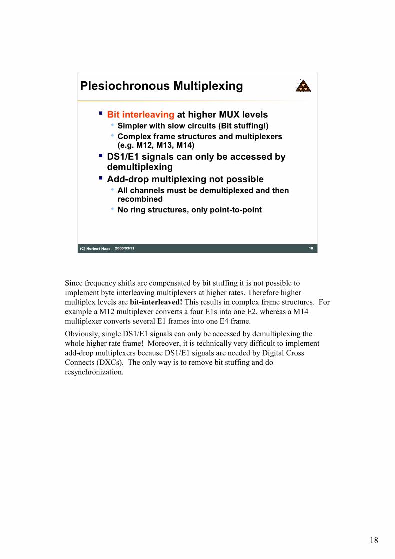
Since frequency shifts are compensated by bit stuffing it is not possible to
implement byte interleaving multiplexers at higher rates. Therefore higher
multiplex levels are bit-interleaved! This results in complex frame structures. For
example a M12 multiplexer converts a four E1s into one E2, whereas a M14
multiplexer converts several E1 frames into one E4 frame.
Obviously, single DS1/E1 signals can only be accessed by demultiplexing the
whole higher rate frame! Moreover, it is technically very difficult to implement
add-drop multiplexers because DS1/E1 signals are needed by Digital Cross
Connects (DXCs). The only way is to remove bit stuffing and do
resynchronization.
19
19(C) Herbert Haas 2005/03/11
Synchronization
M14
+
LT
CB
M14
+
LT
CBDS0
Switch
M14
+
LT
M14
+
LTE1 E4 E1 E1 E4 E1
Asynchronous
transport network
Asynchronous
transport network
Synchronous
MUX
Synchronous
MUX
End-to-End Synchronization
Network Clock
(Stratum 1)
CB ........... Channel Bank
M14+LT ... MUX and Line Termination
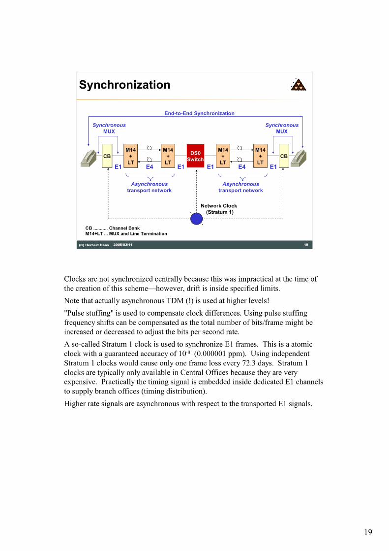
Clocks are not synchronized centrally because this was impractical at the time of
the creation of this scheme�however, drift is inside specified limits.
Note that actually asynchronous TDM (!) is used at higher levels!
"Pulse stuffing" is used to compensate clock differences. Using pulse stuffing
frequency shifts can be compensated as the total number of bits/frame might be
increased or decreased to adjust the bits per second rate.
A so-called Stratum 1 clock is used to synchronize E1 frames. This is a atomic
clock with a guaranteed accuracy of 10-11 (0.000001 ppm). Using independent
Stratum 1 clocks would cause only one frame loss every 72.3 days. Stratum 1
clocks are typically only available in Central Offices because they are very
expensive. Practically the timing signal is embedded inside dedicated E1 channels
to supply branch offices (timing distribution).
Higher rate signals are asynchronous with respect to the transported E1 signals.
20
20(C) Herbert Haas 2005/03/11
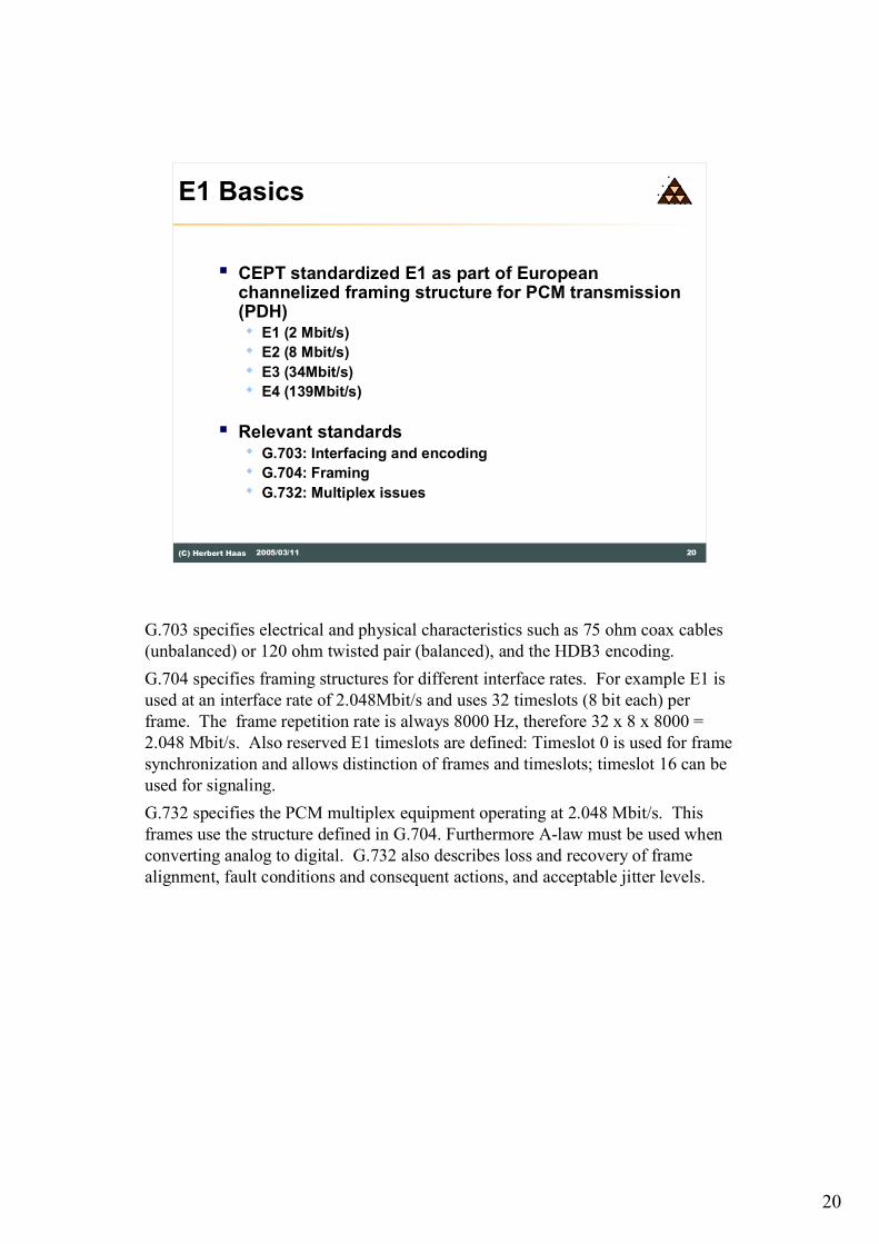
E1 Basics
� CEPT standardized E1 as part of European channelized framing structure for PCM transmission (PDH)� E1 (2 Mbit/s)
� E2 (8 Mbit/s)
� E3 (34Mbit/s)
� E4 (139Mbit/s)
� Relevant standards � G.703: Interfacing and encoding
� G.704: Framing
� G.732: Multiplex issues
G.703 specifies electrical and physical characteristics such as 75 ohm coax cables
(unbalanced) or 120 ohm twisted pair (balanced), and the HDB3 encoding.
G.704 specifies framing structures for different interface rates. For example E1 is
used at an interface rate of 2.048Mbit/s and uses 32 timeslots (8 bit each) per
frame. The frame repetition rate is always 8000 Hz, therefore 32 x 8 x 8000 =
2.048 Mbit/s. Also reserved E1 timeslots are defined: Timeslot 0 is used for frame
synchronization and allows distinction of frames and timeslots; timeslot 16 can be
used for signaling.
G.732 specifies the PCM multiplex equipment operating at 2.048 Mbit/s. This
frames use the structure defined in G.704. Furthermore A-law must be used when
converting analog to digital. G.732 also describes loss and recovery of frame
alignment, fault conditions and consequent actions, and acceptable jitter levels.

21
21(C) Herbert Haas 2005/03/11
frame frame frame frame frame frame frame
8000 frames per second
timeslot 0 timeslot 1 timeslot 2 timeslot 3 timeslot 31.................
C 0 0 1 1 0 1 1
C 1 A N N N N N
Alternating
Frame Alignment Signal (FAS)
Not Frame Alignment Signal (NFAS)
8 bits per timeslot
2.048 Mbit/s
E1 Frame Structure
....
....
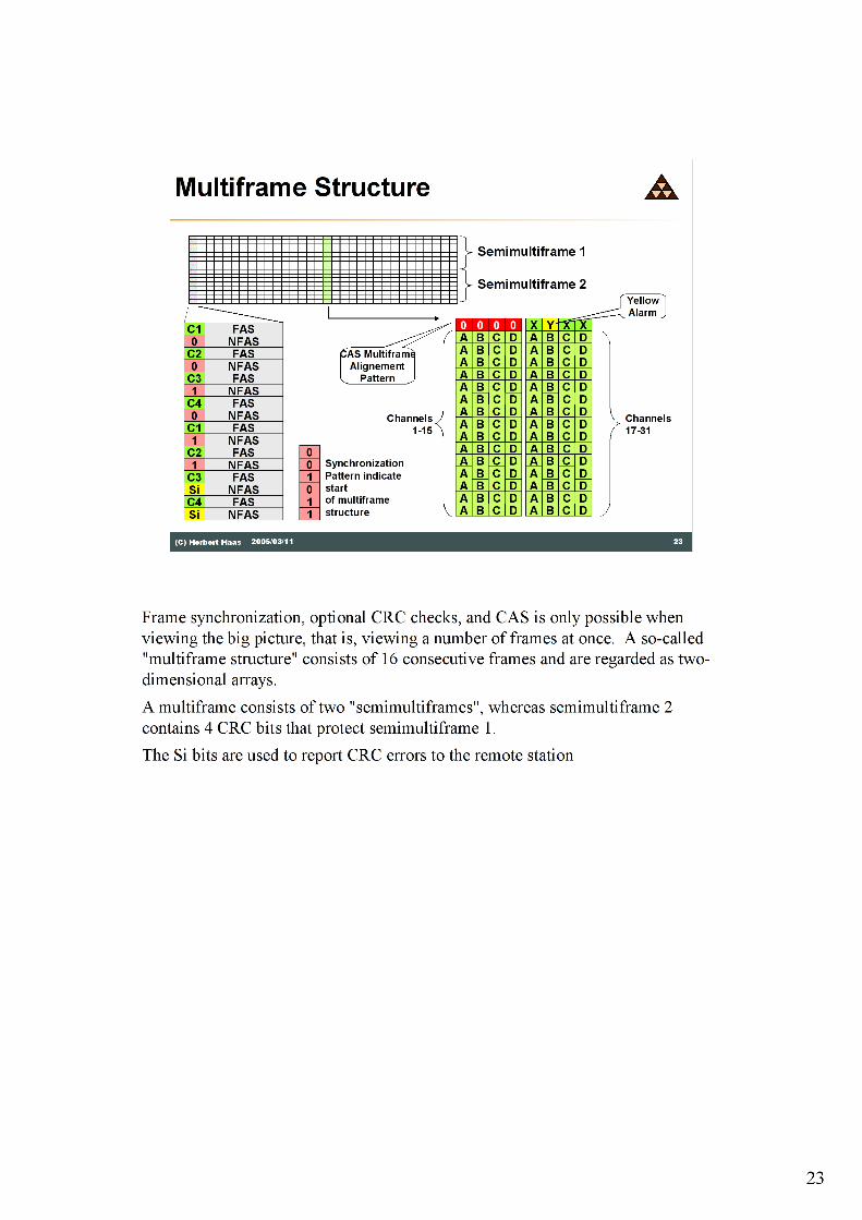
The timeslot 0 is used for frame checking and multiframe synchronization�end-
to-end!
The C (CRC) bit is part of timeslot 0 and can form an optional 4-bit CRC sequence
using 4 consecutive E1 frames. The A (Alarm Indication) bit can transmit a so
called "Yellow" alarm (remote error) to signal loss of signal (LOS) or out of frame
(OOF) condition to the remote station.
N (National) bits are vendor specific and reserved.
22
22(C) Herbert Haas 2005/03/11
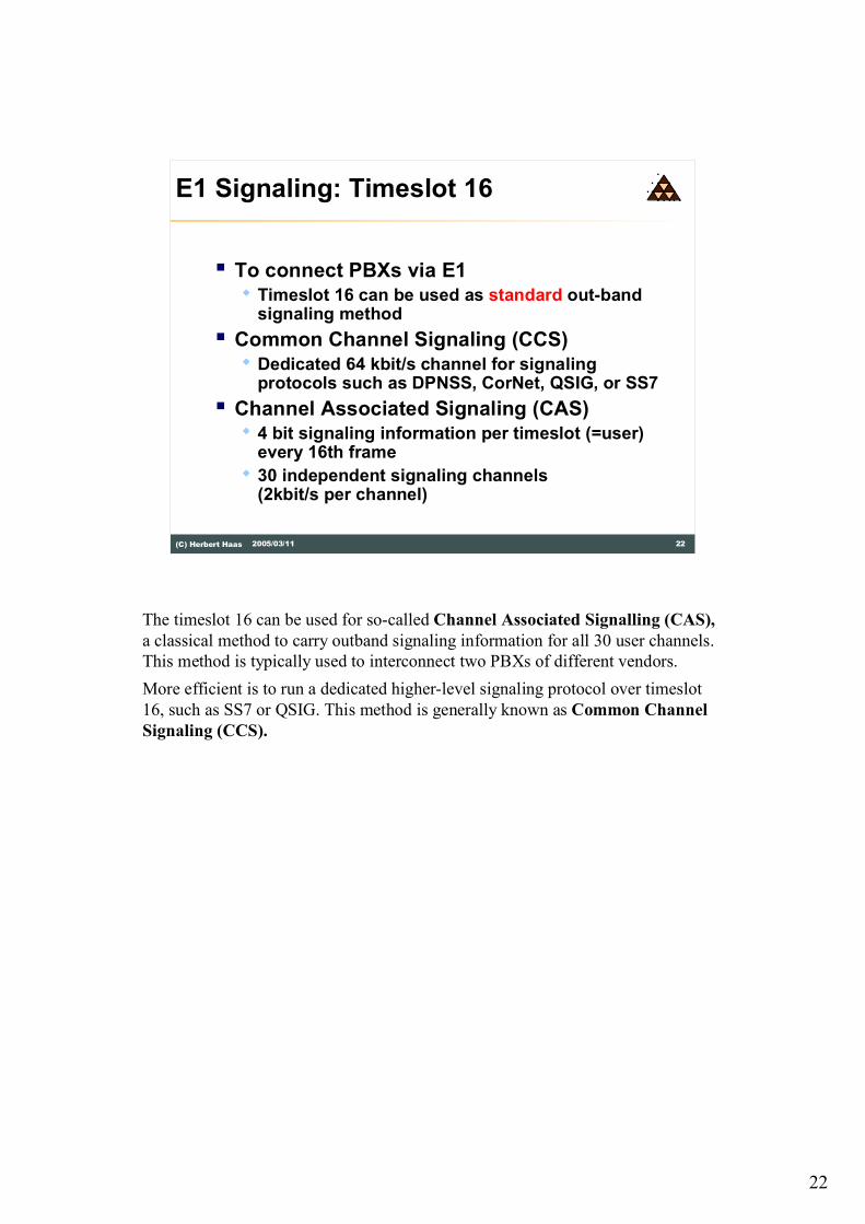
E1 Signaling: Timeslot 16
� To connect PBXs via E1� Timeslot 16 can be used as standard out-band
signaling method
� Common Channel Signaling (CCS)� Dedicated 64 kbit/s channel for signaling
protocols such as DPNSS, CorNet, QSIG, or SS7
� Channel Associated Signaling (CAS)� 4 bit signaling information per timeslot (=user)
every 16th frame
� 30 independent signaling channels (2kbit/s per channel)
The timeslot 16 can be used for so-called Channel Associated Signalling (CAS),
a classical method to carry outband signaling information for all 30 user channels.
This method is typically used to interconnect two PBXs of different vendors.
More efficient is to run a dedicated higher-level signaling protocol over timeslot
16, such as SS7 or QSIG. This method is generally known as Common Channel
Signaling (CCS).
24
24(C) Herbert Haas 2005/03/11
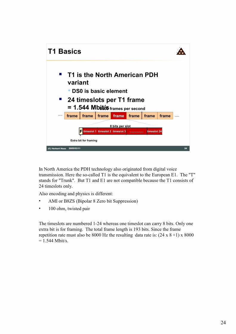
T1 Basics
� T1 is the North American PDH
variant
�DS0 is basic element
� 24 timeslots per T1 frame
= 1.544 Mbit/s
frame frame frame frame frame frame frame
8000 frames per second
F timeslot 1 timeslot 2 timeslot 3 timeslot 24.................
8 bits per slot
Extra bit for framing
........
In North America the PDH technology also originated from digital voice
transmission. Here the so-called T1 is the equivalent to the European E1. The "T"
stands for "Trunk". But T1 and E1 are not compatible because the T1 consists of
24 timeslots only.
Also encoding and physics is different:
� AMI or B8ZS (Bipolar 8 Zero bit Suppression)
� 100 ohm, twisted pair
The timeslots are numbered 1-24 whereas one timeslot can carry 8 bits. Only one
extra bit is for framing. The total frame length is 193 bits. Since the frame
repetition rate must also be 8000 Hz the resulting data rate is: (24 x 8 +1) x 8000
= 1.544 Mbit/s.

25
25(C) Herbert Haas 2005/03/11
T1 Basics
� No reserved timeslot for signaling �
Robbed Bit Signaling
� Combinations of frames to superframes
� 12 T1 frames (DS4)
� 24 T1 frames (Extended Super Frame, ESF)
� Modern alternative: Common Channel
Signaling
T1 framing is often used to connect PBX (Private Branch Exchanges) via leased line hence the signaling information between PBXs must be exchanged. But T1 defines no dedicated timeslot for CAS, instead "robbed bit signaling" is used.
Using CAS the signaling information is transmitted by robbing certain bits, which are normally used for data. The signaling is placed in the LSB of every time slot in the 6th and 12th frame of every D4 superframe (A, B).
Using an Extended Super Frame (ESF) structure, the signaling information is placed in the LSB of every time slot in the 6th, 12th 18th and 24th frame of every ESF superframe (A, B, C, D).
Robbed Bit Signalling does not affect PCM signals (analog sources) but damages data channels completely!
Therefore only 56 kbit/s data channels are possible with CAS. Alternatively, CCS can be used in the same way like E1. For example timeslot 24 can be used as transparent signaling channel. In the USA, ISDN is typically carried over CAS systems because there is still a lot of old equipment used across the country. So only 56 kbit/s per B channel usable. 64 kbit/s B channels would require CCS, which is also called "Clear Channel Capability (CCC)".

26
26(C) Herbert Haas 2005/03/11
PDH Limitations
� PDH overhead increases dramatically with
high bitrates
1%
2%
3%
4%
5%
6%
7%
8%
9%
10%
11%
0.52
2.703.90
6.60 6.25
9.09
10.60
11.76
DS1 DS2 DS3 DS4 CEPT-1 CEPT-2 CEPT-3 CEPT-4
Overhead
The diagram above shows one of the main disadvantages of PDH technologies: the
overhead increases significantly with the data rate, i. e. multiplex level. Thus it is
not reasonable to create much higher signal levels with this technology.
Note that the North American bit robbing method has also one advantage: the total
overhead is much lower compared to the European PDH variant.

27
27(C) Herbert Haas 2005/03/11
Why SONET/SDH?
� Many incompatible PDH implementations
� PDH does not scale to very high bitrates� Increasing overhead
� Complex multiplexing procedures
� Demand for a true synchronous network� No pulse stuffing between higher MUX levels
� Better compensate phase shifts by floating playload and pointer technique
� Demand for add-drop MUXes and ring topologies
In the early 1980s there was a big demand for another backbone technology
because of the severe drawbacks of the old PDH technology.
During the decades, many different PDH implementations were built by different
vendors. Furthermore PDH does not scale to high data rates because of the
overhead problem and because of the complex multiplexing method.
One thing was clear: A successor of PDH�which was supposed to scale up to
infinite data rates�must be truly synchrone. Also flexible topology configurations
should be possible.

28
28(C) Herbert Haas 2005/03/11
History Take 1: USA
� Many companies after divestiture of AT&T� Many proprietary solutions for PDH successor
technology
� In 1984 ECSA (Exchange Carriers Standards Association) started on SONET� Goal: one common standard
� A standard that almost wasn't: over 400 proposals!
� SONET became an ANSI standard� Designed to carry US PDH payloads
In 1984 the Exchange Carriers Standards Association (ECSA) started on the
development of "Synchronous Optical Networks", short: SONET. The goal was to
define one common standard for all companies that were born after the divestiture
of AT&T. Over 400 proposals were sent; but finally, after a long negotiation
period, the SONET standards was born and became an ANSI standard.
First US nation-wide SONET ring backbone were finished in 1997.
29
29(C) Herbert Haas 2005/03/11
History Take 2: World
� In 1986 CCITT became interested in
SONET
� Created SDH as a superset
� Designed to carry European PDH
payloads including E4 (140 Mbit/s)
� Originally designed for fiber optics
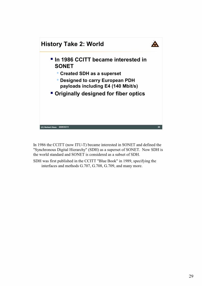
In 1986 the CCITT (now ITU-T) became interested in SONET and defined the
"Synchronous Digital Hierarchy" (SDH) as a superset of SONET. Now SDH is
the world standard and SONET is considered as a subset of SDH.
SDH was first published in the CCITT "Blue Book" in 1989, specifying the
interfaces and methods G.707, G.708, G.709, and many more.

30
30(C) Herbert Haas 2005/03/11
(Regen.Section)
Network Structure
Path
Path Termination
Service (DSn or En) mapping and demapping
PTE PTE
Line
Line termination
(MUX section
termination)
Section
(Regen.) Section
termination
REG REG
Line
Section Section Section
(RegeneratorSection)
(Regen.Section)
(RegeneratorSection)
Path Termination(Regen.) Section
termination
Service (DSn or En) mapping anddemapping
SONETSONET(SDH)(SDH) Terms
ADMor
DCS
(Path Section)
(Multiplex Section) (Multiplex Section)
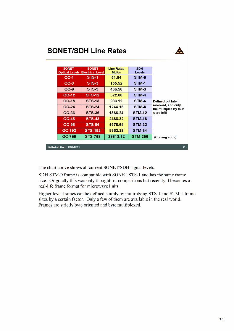
The picture above shows the network structure of a SONET/SDH network.
Although SONET and SDH are compatible, note the slightly different terms
between both worlds.
The "Terminal Multiplexer" represents a so-called "Path Termination" and
marks the edge of the SONET/SDH network (Path) by providing connectivity to
the PDH network devices. A Path is an end-to-end connection between those
Terminal Multiplexers. The "Regenerator" extends the possible distance and
quality of a "Line". The Line spans between a Path termination and a network
node, for example an ADM or DCS. The Regenerator splits a line into multiple
Sections.
The Add/drop multiplexer (ADM) is the main element for configuring paths on
top of line topologies (point-to-point or ring). Using an ADM it is possible to add
or drop multiplexed channels.
The Digital Cross Connect (DCS or DXC) is named after the historical patch
panels used in the early analog backbones. This device is basically a "static
switch" and connects equal-level channels with each other.
31
31(C) Herbert Haas 2005/03/11
Layers and Overhead
� SONET (SDH) consists of 4 layers� Physical Layer
� Section (Regenerator Section) Layer
� Line (Multiplex Section) Layer
� Path Layer
� All layers (except the physical) insert information into the so-called overhead of each frame
� Note: � SONET and SDH are technically consistent, only the
terms might be different
� In this chapter, each SONET term is named first, followed by the associated SDH term written in brackets
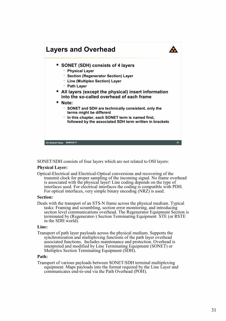
SONET/SDH consists of four layers which are not related to OSI layers:
Physical Layer:
Optical-Electrical and Electrical-Optical conversions and recovering of the transmit clock for proper sampling of the incoming signal. No frame overhead is associated with the physical layer! Line coding depends on the type of interfaces used. For electrical interfaces the coding is compatible with PDH. For optical interfaces, very simple binary encoding (NRZ) is used.
Section:
Deals with the transport of an STS-N frame across the physical medium. Typical tasks: Framing and scrambling, section error monitoring, and introducing section level communications overhead. The Regenerator Equipment Section is terminated by (Regenerator-) Section Terminating Equipment STE (or RSTE in the SDH world).
Line:
Transport of path layer payloads across the physical medium. Supports the synchronization and multiplexing functions of the path layer overhead associated functions. Includes maintenance and protection. Overhead is interpreted and modified by Line Terminating Equipment (SONET) or Multiplex Section Terminating Equipment (SDH).
Path:
Transport of various payloads between SONET/SDH terminal multiplexing equipment. Maps payloads into the format required by the Line Layer and communicates end-to-end via the Path Overhead (POH).

32
32(C) Herbert Haas 2005/03/11
SONET Signals
� Electrical signal: STS-n
� Synchronous Transport Signal level n
� Optical signal: OC-n
� Optical Carrier level n
� OC-nc means concatenated
� No multiplexed signal
� Administrative overhead optimized compared to
multiplexed signal
� Frame format is independent from
electrical or optical signals
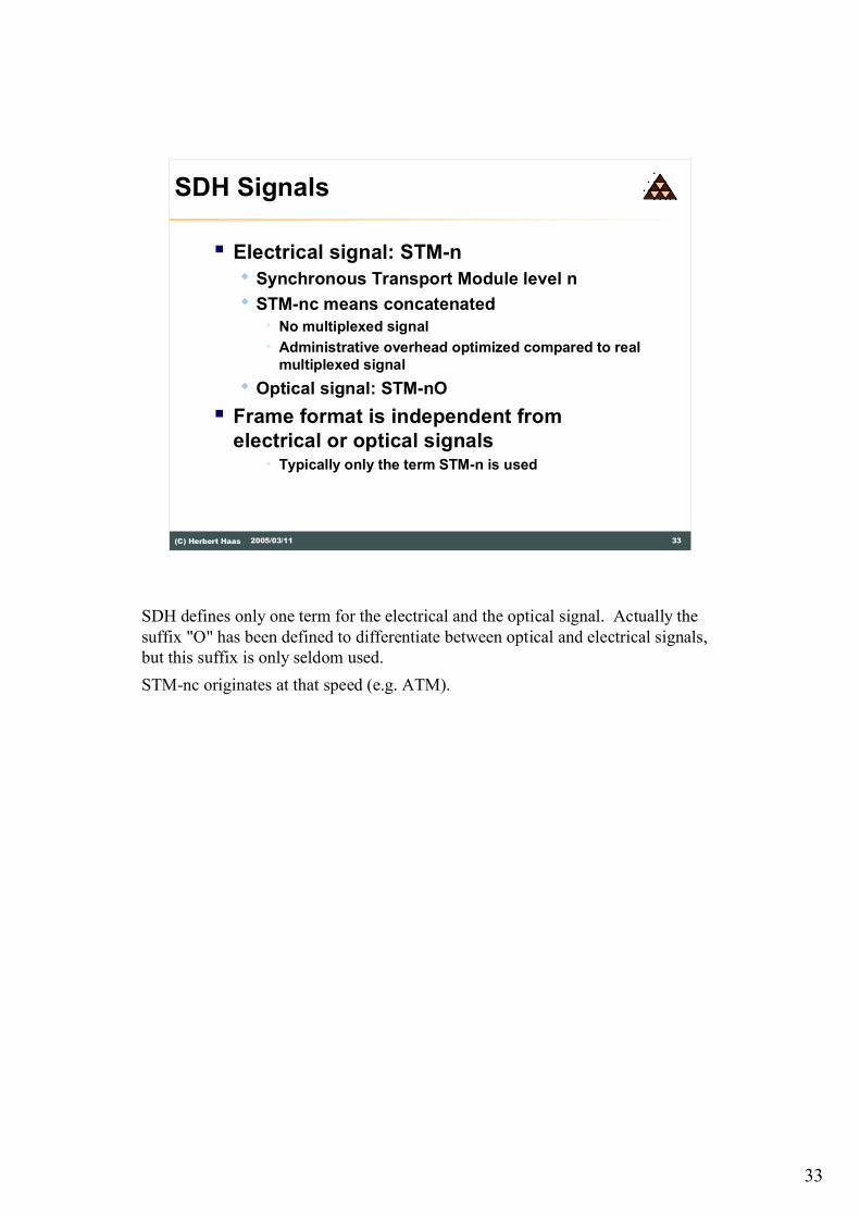
SONET defines different terms for the electrical signal and the optical signal.
OC-nc originates at that speed (e.g. ATM). Typically only the term OC-n is used
(instead of the STS-n terms).
33
33(C) Herbert Haas 2005/03/11
SDH Signals
� Electrical signal: STM-n
� Synchronous Transport Module level n
� STM-nc means concatenated
� No multiplexed signal
� Administrative overhead optimized compared to real
multiplexed signal
� Optical signal: STM-nO
� Frame format is independent from
electrical or optical signals� Typically only the term STM-n is used
SDH defines only one term for the electrical and the optical signal. Actually the
suffix "O" has been defined to differentiate between optical and electrical signals,
but this suffix is only seldom used.
STM-nc originates at that speed (e.g. ATM).
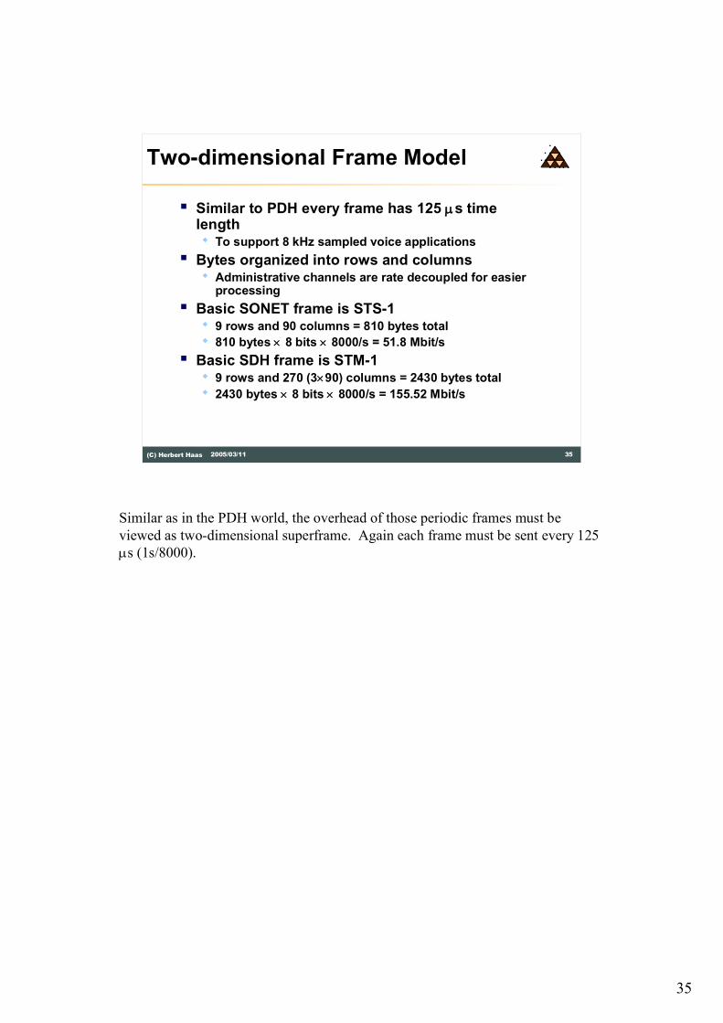
35
35(C) Herbert Haas 2005/03/11
Two-dimensional Frame Model
� Similar to PDH every frame has 125 ms time length� To support 8 kHz sampled voice applications
� Bytes organized into rows and columns� Administrative channels are rate decoupled for easier
processing
� Basic SONET frame is STS-1 � 9 rows and 90 columns = 810 bytes total
� 810 bytes ´ 8 bits ´ 8000/s = 51.8 Mbit/s
� Basic SDH frame is STM-1� 9 rows and 270 (3´90) columns = 2430 bytes total
� 2430 bytes ´ 8 bits ´ 8000/s = 155.52 Mbit/s
Similar as in the PDH world, the overhead of those periodic frames must be
viewed as two-dimensional superframe. Again each frame must be sent every 125
ms (1s/8000).

36
36(C) Herbert Haas 2005/03/11
STS-1 (STM-0) Frame Structure
3 columns 87 columns
90 columns
9 r
ow
s
Transport Overhead
Payload Envelope Capacity (Virtual Container Capacity)
LineOverhead
SectionOverhead
Synchronous Payload Envelope (SPE)
Path
Overh
ead
The STS-1 (STM-0) frame consists of a Transport Overhead (Section Overhead)
and a Payload Envelope Capacity (Virtual Container Capacity). Note that higher
level signals have the same percentage of overhead�the number of columns are
simply multiplied by the rate factor.
The Transport Overhead (TOH) consists of Section Overhead � SOH (Regen.
Section Overhead � RSOH) and a Line Overhead (Multiplex Section Overhead �
MSOH).

37
37(C) Herbert Haas 2005/03/11
Floating Payload
Path Overhe
ad
Pointer Bytes
Synchronous Payload Envelope
The payload is carried inside the Synchronous Payload Envelope or SPE. The SPE
may float inside the Payload Envelope Capacity (Virtual Container Capacity) to
compensate phase and frequency shifts.
The Path Overhead (POH) is the first column of the SPE. Various additional
"envelopes" were defined to support every type of payload e. g. DS1, DS3, E1, E3,
E4, ..., ATM, etc. For this reason the service signals are carried in so-called Virtual
Tributaries (Virtual Containers) which have a defined size to smoothly fit into a
SPE.
38
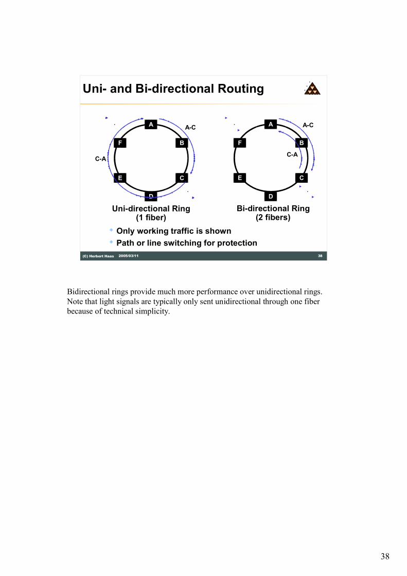
38(C) Herbert Haas 2005/03/11
Uni- and Bi-directional Routing
� Only working traffic is shown
� Path or line switching for protection
A
CE
BF
D
Uni-directional Ring(1 fiber)
C-A
A-CA
CE
BF
D
Bi-directional Ring(2 fibers)
C-A
A-C
Bidirectional rings provide much more performance over unidirectional rings.
Note that light signals are typically only sent unidirectional through one fiber
because of technical simplicity.
39
39(C) Herbert Haas 2005/03/11
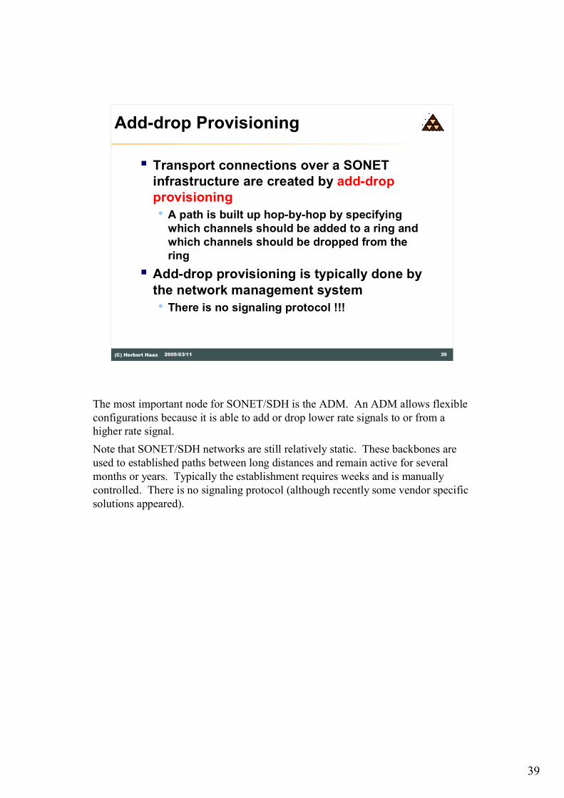
Add-drop Provisioning
� Transport connections over a SONET
infrastructure are created by add-drop
provisioning
� A path is built up hop-by-hop by specifying
which channels should be added to a ring and
which channels should be dropped from the
ring
� Add-drop provisioning is typically done by
the network management system
� There is no signaling protocol !!!
The most important node for SONET/SDH is the ADM. An ADM allows flexible
configurations because it is able to add or drop lower rate signals to or from a
higher rate signal.
Note that SONET/SDH networks are still relatively static. These backbones are
used to established paths between long distances and remain active for several
months or years. Typically the establishment requires weeks and is manually
controlled. There is no signaling protocol (although recently some vendor specific
solutions appeared).

40
40(C) Herbert Haas 2005/03/11
ADM
3
ADM
1
ADM
4OC-12
Drop
Add 1-2, 3
Add 3-4
Drop
Add 4-2
Drop
Add and Drop Example
� Example: OC-12
ring
� Consists of 4 x
OC-3c channels
� Uni-directional
routing
� 2 channels
occupied
ADM
2
Drop & Continue
The picture above illustrates the capabilities of ADMs.

41
41(C) Herbert Haas 2005/03/11
Uni- and Bi-directional Routing
ADM
2
ADM
3
ADM
1
ADM
4ADM
2
ADM
3
ADM
1
ADM
4
Uni-directional routing Bi-directional routing
The picture above illustrates the capabilities of ADMs together with unidirectional
and bidirectional routing.

42
42(C) Herbert Haas 2005/03/11
Operations
� Protection� Circuit recovery in milliseconds
� Restoration� Circuit recovery in seconds or minutes
� Provisioning� Allocation of capacity to preferred routes
� Consolidation� Moving traffic from unfilled bearers onto fewer bearers
to reduce waste trunk capacity
� Grooming� Sorting of different traffic types from mixed payloads
into separate destinations for each type of traffic
SONET/SDH topologies are designed for providing a flexible and reliable
transport for required paths. Capacity planning and bandwidth provisioning is still
a reearch issue. Redundancy and automatic fail-over is provided within 20 ms.
Delay and jitter control through control signals.
Typical topology concepts:
Point-to-point links (with protection) and DCS/MUX allows arbitrary complex
topology to be built.
Interconnected protected rings with ADM/DCS allow for minimum resource usage
(physical media) for avoiding single point of failures.
43
43(C) Herbert Haas 2005/03/11
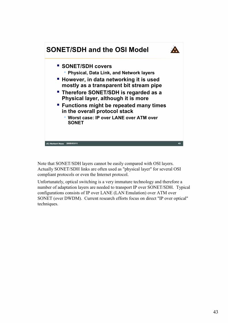
SONET/SDH and the OSI Model
� SONET/SDH covers � Physical, Data Link, and Network layers
� However, in data networking it is used mostly as a transparent bit stream pipe
� Therefore SONET/SDH is regarded as a Physical layer, although it is more
� Functions might be repeated many times in the overall protocol stack� Worst case: IP over LANE over ATM over
SONET
Note that SONET/SDH layers cannot be easily compared with OSI layers.
Actually SONET/SDH links are often used as "physical layer" for several OSI
compliant protocols or even the Internet protocol.
Unfortunately, optical switching is a very immature technology and therefore a
number of adaptation layers are needed to transport IP over SONET/SDH. Typical
configurations consists of IP over LANE (LAN Emulation) over ATM over
SONET (over DWDM). Current research efforts focus on direct "IP over optical"
techniques.
44
44(C) Herbert Haas 2005/03/11
Summary
� Telecommunication backbones must be very reliable and backward compatible
� PDH is still an important backbone technology
� Recently moving to optical backbones using SONET/SDH
� Traffic volume of voice services will decrease relative to general IP traffic