Embed Size (px)
Citation preview

5Jii ~Jj ~ FIRE SERVICES DEPARTMENT
AA! !Wt& ~ :fit !~ ~ LICENSING AND CERTIFICATION COMMAND
5/F, Fire Services Headquarters Buildingil:\"~1L~SRY,\>DJl}lf:[Jm.f!tllf.lti: I l)Jf
No. I Hong Chong Road, Tsim Sha Tsui East
Kowloon, Hong Kong$J!j llJj ~ $1&! ml :k JJl 5 ;ft
:;f;: ~ :fi l)Jf OUR REF.: (9) In FP(LC) 314/07 Pt.10
*W:fi l)Jf YOUR REF.:
Iii >( {!ll 1{ FAX: (852) 2723 2197
ft r !l!jl {lf= E-MAIL: [email protected]
ft /f,5 TEL. NO.: (852) 2733 7619
25 November 2021
To: Recipient ofFSD Circular Letters
Dear Sir/Madam,
FSD Circular Letter No. 9/2021
Revised Annual Inspection Check.lists for
Fire Hydrant/Hose Reel Systems and Supply Tanks
This letter serves to announce the revision of annual inspection (AI) checklists for
fire hydrant/hose reel (FH/HR) systems (Annex A) and supply tanks (Annex B) and should be
read in conjunction with FSD Circular Letter No. 4/2019 "Annual Inspection Checklists for
Fire Hydrant/Hose Reel Systems and Supply Tanks" issued on 13 December 2019. The
checklists annexed to FSD Circular Letters No. 4/2019 (English version) and No. 2/2020
(Chinese version) are hereby superseded by these revised ones.
The revisions to the existing checklists were made upon extensive consultation with
local trade members. Major changes include, but are not limited to, the addition ofappendices,
which are designed for certain components/installations to facilitate the completion of the
checklists, if applicable.
As a reminder, registered fire service installation contractors (RFSICs) shall
conductAis against the checklists, which specify the minimum requirements for Als, regardless
of the time of submission of building plans of the subject building for approval. Items on the
checklists and their appendices/tables, if applicable, to the FH/HR systems and supply tanks in
Reference number and date should be quoted in reference to this letter fl.. ¥,i & :$: IB ll't fR 51 ill :!ill lllft ;f!J El Jill
- P.2 -
the buildings/premises, shall be inspected/tested. RFSICs shall, after inspection, complete the
checklists by indicating, where appropriate, whether the inspected and tested items conform to
the standards/requirements stipulated in the appropriate version of the Code of Practice for
Minimum Fire Service Installations and Equipment.
In addition, RFSICs shall duly observe the principles and requirements regarding
"Completion of checklists for Al" and "Duty and responsibility of RFSICs" as stated in
FSD Circular Letter No. 4/2019. It is important for RF SI Cs to note that it is their
responsibility to make sure that the FSis are in efficient working order and conforming to the
requirements specified in the Code of Practice for Minimum Fire Service Installations and
Equipment and that the inspection, testing and maintenance are conducted in accordance with
the Code of Practice for Inspection, Testing and Maintenance of Installations and Equipment.
The revised AI checklists for FH/HR systems and supply tanks (Rev. 01, FSD
Circular Letter No. 9/2021) will take effect on 1 February 2022 to allow more time for the
trade to get acquainted with them. Meanwhile, checklists for other fire service installations
and equipment will be revised/devised for promulgation in due course.
For enquiries, please contact our Fire Service Installations Task Force at 2733 1567
during office hours.
Yours faithfully,
for Director of Fire Services
Encl.
Reference number and date should be quoted in reference to this letter n ~ & ~ fa llij r~ sl }I!b mfJl!t w a wi

Annex A
Annual Inspection Check.list for Fire Hydrant/Hose Reel Systems
RFSIC Ref.: .......................... .
Serial no. of FS 251: ...................................................................................................................................................................... .
Completion Date of Annual Inspection: ................................................................................................................................................ .
Building/Premises Address: .................................................................................................................................................. .
The annual inspection is conducted in accordance with:-
(a) the appropriate version of the Code of Practice for Minimum Fire Service Installations and Equipment promulgated by the Director
of Fire Services;
(b) the Code of Practice for Inspection, Testing and Maintenance of Installations and Equipment promulgated by the Director of Fire
Services;
(c) the relevant requirements applicable to the system(s) installed in the buildings/premises; and
(d) the relevant Circular Letters promulgated from time to time by the Fire Services Department.
See Table I for the Fire Hydrant Flow Rate/Pressure Test Record.
1. Type ofWater Supply
(Please insert a" ✓" in the appropriate box)
Remarks
a. Direct town main connection without any pump/tank [ ] Where applicable, parts of the water supply portion that need
inspection are listed in Appendix I.b. F.S. tank refilled directly from town main [ ]
c. F.S. tank refilled from town main via a transfer
pumping installation
[ ] Where applicable, parts of the water supply portion that need
inspection are listed in the Annual Inspection Checklist for
Water Supplies.
d. Internal fire main which serves more than one building
and/or system.
[ ] Where applicable, parts of the water supply portion that need
inspection are listed in Appendix I.
When water tank(s) is/are involved, parts of the water supply portion that need inspection are listed in the Annual Inspection Checklist for
Supply Tanks.
Remark: I. "Yes" denotes compliance with the FSD's requirements. "No" denotes non-compliance with the FSD's requirements. "NIA"
denotes not applicable. Please insert a" ✓" in the appropriate box.
2. If there are any items found to be non-compliant with the FSD's requirements, please indicate its location in the "Remarks"
column.
NIA Remarks
2. F.S. Pump Installation (where provided)
Findings of the annual inspection ofF.S. pump installation are recorded in Appendix II.
[ ] IfN/A, go to 4
3. Intermediate Booster Pump Installation (where provided) [ ] IfN/A, go to 4
Findings of the annual inspection of intermediate booster pump installation are recorded in Appendix
III.
Al Checklist - FH/HR Systems (Rev. 01, FSD Circular Letter No. 9/2021) 1/7

Annual Inspection Checklist for Fire Hydrant/Hose Reel Systems
Yes No NIA Remarks
4. Fire Hydrant (where applicable) [ ] IfN/A, go to 5
a. The fire hydrant(s), including the body, outlet(s), hand-wheel(s), stem(s), cap(s)
and chain(s), pressure reducing facility and other accessories, where applicable,
is/are intact and free from leakage and undue corrosion.
[ ] [ ] [ ] ........................
························
........................
b. The gasket(s) at the fire hydrant outlet coupling(s), where applicable, is/are
intact and free from undue deterioration.
[ ] [ l [ ] ························ ........................
c. The fire hydrant(s) is/are duly lubricated and tested to operate freely between
fully open and fully closed.
[ ] [ l [ ] ························ ........................
d. An automatic air vent valve is provided at the appropriate position of the rising
main(s).
[ ] [ ] [ ] ························
........................
e. The fire hydrant(s) is/are clear of obstructions and can be used freely. [ ] [ ] [ ] ........................
························ f. For fire hydrants installed inside cabinets, each cabinet is properly labelled and
its door can be opened easily without the use of any tool.
[ ] [ ] [ ] ........................
........................
5. Hose Reel [ ] IfN/A, go to 6
a. The hose reel(s), including the body, hose, nozzle, glass-fronted nozzle cabinet,
striker, swing arm assembly and other accessories, where applicable, is/are
intact, securely mounted, and free from leakage and undue corrosion.
[ ] [ ] [ ] ........................
························
........................
b. The hose reel drum(s) is/are painted in red. [ ] [ ] [ ] ························ ........................
c. The glass-fronted cabinet(s) for nozzles is/are of a size and design which allow
the free use of the hose reel(s) and the glass panel(s) is/are easily frangible with
a thickness of l.5 mm or less.
[ ] [ ] [ ] ........................
························
························ d. The fixed type hose reel(s), where provided, is/are equipped with a hose guide. [ l [ ] [ ] ........................
························ e. The control valve(s), pipework and accessories are intact, securely supported,
and free from leakage and undue corrosion.
[ ] [ ] [ ] . .......................
. .......................
f. The control valve(s) is/are duly lubricated and tested to operate freely between
fully open and fully closed.
[ ] [ ] [ ] ........................
........................
g. For recessed type hose reels, where provided, the control valve and nozzle when
recessed are in a position within 500 mm from the front wall surface.
[ l [ ] [ ] ........................
························
h. The cabinet(s), where provided, for housing the hose reel(s), is/are labelled
"FIRE HOSE REEL ;f!:j~JJ~ffi" in lettering of at least 50 mm high.
[ ] [ ] [ ] ························
························
AI Checklist - FH/HR Systems (Rev. 01, FSD Circular Letter No. 9/2021) 2/7

Annual Inspection Check.list for Fire Hydrant/Hose Reel Systems
Yes No NIA Remarks
i. Except the cabinets fitted with an easily frangible glass panel, the door(s) fitted
to the cabinet(s), where provided, for housing the hose reel(s), can be opened
without the use of any key.
[ ] [ ] [ ] ........................
........................
························ j. The drum, nozzle and swing arm assembly, where applicable, of the hose reel(s)
are duly lubricated and tested to operate freely through their full range of
operation.
[ ] [ ] [ ] ························
························ ........................
k. The hose reel(s) and the associated manual call point(s) are clear ofobstructions
and can be used freely.
[ ] [ ] [ ] ························ ........................
I. A legible standard operation instruction notice is affixed to the wall in a
prominent position adjacent to the hose reel(s). For hose reels installed inside
cabinets, where applicable, such notice is affixed to the cabinet door.
[ ] [ ] [ ] ························ ........................
........................
m. The hose reel(s) is/are capable of producing a jet of6 m in length. [ ] [ ] [ ] ........................
........................
n. An automatic air vent valve is provided at the appropriate position of the rising
main(s).
[ ] [ ] [ ] ........................
........................
6. F.S. Inlet [ ] IfN/A, go to 7
a. The F.S. inlet(s), including the body, couplings, hand-wheel, stems, built-in non-
return valves and other accessories, where applicable, is/are intact and free from
leakage and undue corrosion.
[ ] [ ] [ ] ························
........................
........................
b. The F.S. inlet(s) is/are equipped with a drain cock for pressure relief, and the
drain cock is tested to be in working order.
[ ] [ ] [ ] ........................
........................
c. The F.S. inlet(s) is/are duly lubricated and tested to operate freely between fully
open and fully closed and the internal disc assembly can manoeuvre freely
through its full range of operation.
[ ] [ ] [ ] ........................
························
························
d. For F.S. inlet(s) with a built-in stop valve installed/ last inspected in detail more
than 4 years ago, the stop valve together with the bonnet, stem, disc and disc seat
assembly should be taken out for detailed inspection to verify that all
components are intact, free from undue corrosion and in working order. The date
of installation/the last detailed inspection is displayed conspicuously on the
inlet(s).
[ ] [ ] [ ] ........................
........................
........................
........................
························
························
e. The F.S. inlet cabinet(s) is/are intact and properly protect(s) the inlet(s) against
corrosion and abuse.
[ ] [ ] [ ] ........................
........................
f. The F.S. inlet cabinet(s) is/are properly labelled "FS INLET Jf~jj,,\Jj(l!}l!" in
lettering of at least 50 mm high.
[ ] [ ] [ ] ........................
........................
AI Checklist - FH/HR Systems (Rev. 01, FSD Circular Letter No. 9/2021) 3/7

Annual Inspection Checklist for Fire Hydrant/Hose Reel Systems
Yes No NIA Remarks
g. For buildings equipped with more than one FH/HR systems, where F.S. inlets of [ ] [ ] [ ] ························
the systems are not interconnected, each F.S. inlet is properly labelled in terms ························
of the block(s)/area(s) of the building being served as applicable. ························
h. The F.S. inlet(s) is/are clear of obstructions and can be used freely. [ ] [ ] [ ] ························ ........................
i. The F.S. inlet(s) is/are affixed with a metal identification plate raised or engraved [ ] [ ] [ ] ························ with the English and Chinese characters of at least 50 mm high. ························
j. For systems equipped with intermediate booster pump(s), the intermediate [ ] [ ] [ ] ........................
booster pump start/stop buttons and the audio and/or visual alarm(s) adjacent to ........................
the corresponding F.S. inlet(s) are intact, securely mounted, properly wired, ························ properly labelled and free from undue deterioration. ························
k. The cables and cable containment for all electrical components, where [ ] [ ] [ ] ........................
applicable, are intact, securely mounted, properly wired, and free from undue ························ deterioration. ························
I. The intermediate booster pump start/stop buttons and the audio and/or visual [ ] [ ] [ ] ........................
alarm(s) are tested to be in working order. ........................
m. The pipework, valves and accessories, where applicable, are intact, securely [ ] [ ] [ ] ························ supported, and free from leakage and undue corrosion. ························
n. The support and brackets are intact and free from distortion and undue corrosion. [ ] [ ] [ ] ························
························
7. Pressure Reducing Valve (PRY) (where provided)
Findings of the annual inspection for pressure reducing valve set(s) is recorded in Appendix IV.
[ ] IfN/A, go to 8
8. Pipework, Valves and Equipment
a. The pipework, valves, strainers, expansion joints, equipment and accessories,
where appropriate, are intact, securely supported and free from leakage,
distortion and undue corrosion.
[ ] [ ] [ ] ························
........................
························
b. The support and brackets are intact and free from distortion and undue corrosion. [ ] [ ] [ ] ························
........................
c. The strainer(s), where applicable, is/are free from blockage and the screen(s)
inside is/are cleaned.
[ ] [ ] [ ] ························
........................
d. The stop valve(s), where applicable, is/are duly lubricated and tested to operate
freely between fully open and fully closed and is/are set at its/their correct (fully
open or fully closed) position(s) after the tests.
[ ] [ ] [ ] ........................
························
........................
Al Checklist - FH/HR Systems (Rev. 01, FSD Circular Letter No. 9/2021) 4/7

Annual Inspection Checklist for Fire Hydrant/Hose Reel Systems
Yes No NIA Remarks
e. Where applicable, the stop valves are padlocked and labelled "Normally Open
'i¥tlm" or "Normally Closed 'i¥t~ffl'' as appropriate.
[ ] [ ] [ ] ························
........................
f. The automatic air vent valve(s), where provided, is/are intact, with the vent
opening unobstructed (not capped closed).
[ ] [ ] [ ] ........................
························
9. Sprinkler Installation Extended from FH/HR System for Protecting (a) Refuse Chute(s), etc.
(where provided)
Findings of the annual inspection for sprinkler installation extended from FH/HR System are recorded
in Appendix V.
[ ] IfN/A, go to 10
10. Other Observations
a. For pump rooms/enclosures, where applicable, the entrance door(s) is/are kept
locked.
[ ] [ ] [ ] ························ ........................
b. For pump spaces, where applicable, the direct access to the pump space(s) is
maintained available.
[ ] [ ] [ ] ........................
························ c. The pump room(s)/enclosure(s)/space(s) as applicable, is/are kept clear of
storage and waste materials.
[ ] [ ] [ ] ........................
························
d. The artificial lighting, where provided, at pump room(s)/enclosure(s)/space(s) is
operating properly.
[ ] [ ] [ ] ························ ........................
e. For underground pump rooms, where applicable, the submersible drainage
pumping installation, where provided, is in working order.
[ ] [ ] [ ] ........................
........................
f. The opening(s) for the passage of pipes or cables through a required fire barrier
is/are protected with fire seals or fire stops to maintain the required fire resisting
properties of the fire barrier.
[ ] [ ] [ ] ........................
........................
........................
AI Checklist - FH/HR Systems (Rev. 0 I, FSD Circular Letter No. 9/2021) 5/7

Annual Inspection Checklist for Fire Hydrant/Hose Reel Systems
Note:
I. All items under part 10 - Other Observations are not related to the functionality of fire service installations and equipment (FSis) and
hence shall not be reflected in FS 251. However, owners of FSis bear the responsibility to rectify any irregularities noted thereunder.
2. This checklist specifies the minimum requirements for annual inspection for fire hydrant/hose reel systems. Incomplete inspections
or inspections not conducted in full accordance with this checklist shall not be recognised as properly completed annual inspections.
Authorized Signatory of RFSIC:
(Name in Full) (Signature)
(Date)
Registered Fire Service Installation Contractor:
(FSD/RC No.) (Company Name)
(Company Stamp)
AI Checklist- FH/HR Systems (Rev. 01, FSD Circular Letter No. 9/2021) 617

---
Annual Inspection Checklist for Fire Hydrant/Hose Reel Systems
Table I Sheet No. ____ of____
Fire Hydrant Flow Rate/Pressure Test Record
Building/Premises Address:--------------------------------------------
Building/Block Name:-----------------------------------------------
Zero Flow Conforms to
Tested Fire Water Supply Source Pressure RemarksFire Hydrant Zone No.
Hydrant
Jockey Pump
From IF
at Staircase
to IF
No. ___
From
at Staircase
to
No.
F.S. Tank Gravity Supply
Remark: For jockey pump, only testing on zero-flow pressure is required. For other water supply sources, testing on zero-flow pressure and pressure at rated flow are required.
AI Checklist - FH/HR Systems (Rev. OJ, FSD Circular Letter No. 9/2021) 7/7

Annual Inspection Checklist for Fire Hydrant/Hose Reel Systems
Appendix I
Town Main/Internal Fire Main Connection
Remarks: Appendix I is only applicable to FH/HR systems that:
(a) is fed directly from the town main without a F.S. tank; or
(b) has a F.S. tank refilled directly from the town main without any transfer pumping installation; or
(c) is fed from an internal fire main which serves more than one building and/or system.
If not applicable, skip this Appendix.
Al. Town Main/Internal Fire Main Connection Yes No NIA Remarks
a. All pipework, stop valve(s), check valve(s) and backflow preventer(s), where
applicable, are securely supported, intact and free from leakage and undue
corrosion.
[ l [ l [ l ························
........................
........................
b. Other than the anti-pollution valve, where provided, all stop valves are
padlocked where applicable.
[ l [ l [ l ........................
........................
c. All stop valves are duly lubricated, tested to operate freely between fully open
and fully closed and set at their correct (fully open or fully closed) positions after
the test.
[ l [ l [ l ........................
........................
........................
d. Where applicable, all stop valves are labelled "Normally Open '/It lffl" or
"Normally Closed '/ltrul" as appropriate.
[ ] [ ] [ l ........................
........................
e. The anti-pollution valve, where provided, is properly labelled in terms of usage. [ ] [ ] [ ] ........................
........................
f. The backflow preventer(s), where provided, is/are tested to be in working order. [ ] [ l [ l ························
........................
g. The electrical monitoring switch(es) for stop valves, where provided, is/are
intact, properly wired, and tested to be in working order.
[ l [ l [ ] ........................
........................
h. The cables and cable containment for electrical monitoring switch(es), where
provided, are intact, securely mounted, properly wired, and free from undue
deterioration.
[ l [ ] [ l ........................
........................
........................
AI Checklist - FH/HR Systems (Rev. 01, FSD Circular Letter No. 9/2021) ill-Appendix I

Annual Inspection Checklist for Fire Hydrant/Hose Reel Systems
Appendix II
F.S. Pump Installation
Remark: Appendix II is only applicable to FH/HR systems equipped with F.S. pumps. If not applicable, skip this Appendix.
A.2 Pump Installation Yes No NIA Remarks
A2.l Pump Room/Enclosure (where applicable) [ ] IfN/A, go toA2.2
a. The room(s)/enclosure(s) shelter(s) the pump(s) from tampering/inclement
weather.
[ ] [ ] [ ] ························
························
b. The room(s)/enclosure(s) is/are properly labelled in terms of usage. [ ] [ ] [ ] ························
························· A2.2 Pump Space (for pumps mounted on spreaders or flat roofs where applicable) [ ] IfN/A, go to A2.3
a. The pump space(s) is/are properly labelled in terms of usage. [ ] [ ] [ ] ························
························
b. The electrical equipment, pump control panel(s) and cable connections as
applicable, within the pump space(s) are protected against ingress of water.
[ ] [ ] [ ] ························
························
A2.3 Pump Foundation
a. The pump plinth(s)/spreader(s) is/are intact and free from deformation,
settlement and undue corrosion.
[ ] [ ] [ ] ························
························ b. The anti-vibration mounting(s), where provided, is/are intact and free from
undue settlement.
[ ] [ ] [ ] ························
························ A2A Pump Set (Pump and Driver)
a. The pump set(s) together with the base plate(s) as applicable, is/are intact,
securely mounted and free from settlement.
[ ] [ ] [ ] ························
························ b. The guard(s) for the coupling/shaft/belt-driving parts as applicable, is/are
intact and securely mounted.
[ ] [ ] [ ] ························
························ c. The pump coupling cushions and shaft alignment are checked and re-aligned
where necessary.
[ ] [ ] [ ] ························
························ d. The belts and pulleys, where provided, are intact and free from cracks, damage
and undue deterioration.
[ ] [ ] [ ] ························
························ e. The alignment and tightness of the belts, where provided, are tested and re-
adjusted where necessary.
[ ] [ ] [ ] ························
························ f The shaft bearings and shaft coupling are lubricated. [ ] [ ] [ ] ························
························
g. The packing for the pump shaft(s) is checked and re-adjusted to suitable
tightness where necessary.
[ ] [ ] [ ] ························
························ h. An air vent valve is provided at the appropriate position of the pump casing
for pump(s) which is/are capable of trapping air inside the casing.
[ ] [ ] [ ] ························
························
Al Checklist- FH/HR Systems (Rev. 01, FSD Circular Letter No. 9/2021) 1/6-Appendix II

Annual Inspection Checklist for Fire Hydrant/Hose Reel Systems
Yes No NIA Remarks
i. The pump set(s) is/are kept fully primed and pump set(s) under negative
suction condition, where applicable, is/are equipped with a priming tank.
[ ] [ ] [ ] ························
. .......................
A2.5 Pipework, Valves, Equipment and Accessories
a. The pipework, valves, strainers, expansion joints, flexible connectors,
equipment and accessories as applicable, are intact, securely supported, and
free from leakage, distortion and undue corrosion.
[ ] [ l [ ] ........................
........................
························ b. The support and brackets are intact and free from distortion and undue
corrosion.
[ ] [ l [ ] ........................
........................
c. The strainer(s), where provided, is/are free from blockage and the screen(s)
inside is/are cleaned.
[ ] [ ] [ ] ························
........................
d. The stop valves are duly lubricated and tested to operate freely between fully
open and fully closed and are set at their correct (fully open or fully closed)
positions after the tests.
[ l [ l [ l ························ ........................
........................
e. Where applicable, the stop valve(s) is/are padlocked and properly labelled
"Normally Open 'rltlm" or "Normally Closed 'rlt~ffl" as appropriate.
[ l [ l [ ] ························
........................
f The electrical monitoring switch(es) for stop valves, where provided, is/are
intact, properly wired, and tested to be in working order.
[ ] [ l [ l ........................
························ g. The pressure switch(es), where provided, is/are intact, properly wired, and
labelled in terms ofusage.
[ l [ l [ l ........................
························
h. The reading(s) on the pressure gauge(s) is/are within the acceptable range. [ l [ l [ l ........................
........................
i. The automatic air vent valve(s), where provided, is/are intact, with the vent
opening unobstructed (not capped closed).
[ l [ l [ l ························
························ A2.6 Electrical Equipment, Cables and Cable Containment
a. The power supply switch(es), busbar chamber(s), pump control panel(s) and
electrical equipment, where applicable, are intact, securely mounted, properly
labelled and free from undue corrosion.
[ l [ l [ ] ························
........................
........................
b. The fuses in the power supply circuit and control circuit as applicable, are of
the correct ratings and intact.
[ l [ l [ l ························ ........................
c. The cables and cable containment are intact, securely mounted, properly
wired, and free from undue deterioration.
[ l [ l [ l ························ ........................
d. The power supply switches are tested to be operating properly and are switched
on after the test.
[ l [ l [ l ························ ........................
AI Checklist • FH/HR Systems (Rev. 0 I, FSD Circular Letter No. 9/2021) 2/6-Appendix II

Annual Inspection Checklist for Fire Hydrant/Hose Reel Systems
Yes No NIA Remarks
e. The contactor(s), relay(s), timer(s), interface module(s), switch(es), circuit
breaker( s ), indicator(s), terminal block(s) and other components, where
applicable, and the wirings inside the pump control panel(s) are intact,
properly wired and free from any sign of damage/overheating and undue
deterioration.
[ ] [ ] [ ] ························
························
························
························
························
f. The control buttons, switches, indicators and meters are properly labelled in
terms of usage.
[ ] [ ] [ ] ························
························
g. The reading(s) on the voltmeter(s), where provided, is/are within the
acceptable range.
[ ] [ ] [ ] ························
························
h. The reading(s) on the ammeter(s), where provided, is/are within the acceptable
range.
[ ] [ ] [ ] ························
························
i. The control buttons and switches are tested to operate properly and are in the
correct positions.
[ ] [ ] [ ] ························
························
j. The switch(es) for suspending pump operation, where provided, is/are in the
correct position(s).
[ ] [ ] [ ] ························
························
k. The indicator(s), where provided, is/are tested to operate properly and are in
proper status.
[ ] [ ] [ ] ························
························ A2.7 As-built Framed Schematic Diagram (where provided) [ ] IfN/A, go toA2.8
Legible as-built system schematic diagram(s) is/are displayed conspicuously at the
pump room/enclosure/space.
[ ] [ ] [ ] ························
........................
A2.8 Operation of Jockey Pump (where provided) [ ] lfN/A, go to A2.9
a. The jockey pump can be started and stopped by the corresponding start and
stop buttons on the pump control panel respectively.
[ ] [ ] [ ] ························
························ b. The jockey pump operates upon a system pressure drop and stops when the
system pressure resumes. The pressure switch setting is checked and re-
adjusted where necessary.
[ ] [ ] [ ] ························
························
························ c. Upon activation of the lock-off button and/or other switches, where provided,
at the pump room/enclosure/space for suspending the operation of the jockey
pump, the fault alarm signal(s), where provided, on the pump control panel
and/or the F.S. control and indicating panel as appropriate is/are in working
order.
[ ] [ ] [ ] ························
························
························
························
························
d. The thermal overload relay and/or the like, where provided, can give fault
signal indication (while not stopping pump operation).
[ ] [ ] [ ] ························
························ e. When the jockey pump operates, the discharge pressure reading, the full load
voltage readings and the full load current readings at all phases are within the
acceptable ranges.
[ ] [ ] [ ] ························
························
························
AI Checklist - FH/HR Systems (Rev. 0 I, FSD Circular Letter No. 9/2021) 3/6-Appendix II

Annual Inspection Checklist for Fire Hydrant/Hose Reel Systems
Yes No NIA Remarks
f After running the jockey pump for not less than 10 minutes, the pump
operation is free from abnormal noise, excessive vibration, undue leakage,
overheating and other signs of malfunction. (Remark: A hose reel nozzle may
be set to discharge to effect cooling of the pump.)
[ ] [ ] [ ] ........................
........................
........................
........................
g. The jockey pump status indicator(s), where provided, on the pump control
panel and/or the F.S. control and indicating panel as appropriate is/are tested
to be in working order by simulating the respective scenarios.
[ ] [ ] [ ] ························
........................
. .......................
A2.9 Operation of Fixed Fire Pump
a. Fixed fire pump no. I can be started and stopped by the corresponding start
and stop buttons on the pump control panel respectively.
[ ] [ ] [ ] ························
························ b. Ditto but for fixed fire pump no. 2, where provided. [ ] [ ] [ ] ........................
........................
c. When assigned as the duty pump, fixed fire pump no. I operates upon receipt
of a fire alarm signal from any manual call point and can only be stopped
manually in the pump room/enclosure/space after the fire alarm signal has
been cleared.
[ ] [ ] [ ] ························
························ ........................
························ d. Ditto but for fixed fire pump no. 2, where provided. [ ] [ ] [ ] ························
........................
e. For fixed fire pumps designed to operate upon a system pressure drop, where
applicable, fixed fire pump no. I when assigned as the duty pump, operates
upon a system pressure drop and can only be stopped manually in the pump
room/enclosure/space after the system pressure has resumed. The pressure
switch setting is checked and re-adjusted where necessary.
[ ] [ ] [ ] ........................
························
························ ........................
························ f. Ditto but for fixed fire pump no. 2, where provided. [ ] [ ] [ ] ························
........................
g. Upon activation of the lock-off button and/or other switches, where provided,
at the pump room/enclosure/space for suspending the operation of fixed fire
pump no. 1, the fault alarm signal(s), where provided, on the pump control
panel and/or the F.S. control and indicating panel as appropriate is/are in
working order.
[ ] [ ] [ ] ························
························
························
························
························ h. Ditto but for fixed fire pump no. 2, where provided. [ ] [ ] [ ] ........................
........................
i. The thermal overload relay and/or the like, where provided, for fixed fire pump
no. 1 can give fault signal indication (while not stopping pump operation).
[ ] [ ] [ ] ························
························
j. Ditto but for fixed fire pump no. 2, where provided. [ ] [ ] [ ] ........................
........................
AI Checklist -FH/HR Systems (Rev. 01, FSD Circular Letter No. 9/2021) 4/6-Appendix II

Annual Inspection Checklist for Fire Hydrant/Hose Reel Systems
Yes No NIA Remarks
k. When started, fixed fire pump no. 1 accelerates to full speed within an
acceptable time frame.
[ ] [ ] [ ] ........................
........................
I. Ditto but for fixed fire pump no. 2, where provided. [ ] [ ] [ ] ························ ........................
m. The anti-overheating circulating pipe/relief valve, where provided, operates
properly when fixed fire pump no. 1 churns.
[ ] [ ] [ ] . .......................
························ n. Ditto but for fixed fire pump no. 2, where provided. [ ] [ ] [ ] ························
........................
0. Fixed fire pump no. I is tested to be capable of delivering adequate flow and
pressure to the system and the results are recorded in Table I.
[ ] [ ] [ ] ························ ........................
p. Ditto but for fixed fire pump no. 2, where provided. [ ] [ ] [ ] ························
........................
q. When fixed fire pump no. I is delivering the rated flow, the voltage readings
and the current readings at all phases are within the acceptable ranges.
[ ] [ ] [ ] ........................
........................
r. Ditto but for fixed fire pump no. 2, where provided. [ ] [ ] [ ] ························
························ s. After running fixed fire pump no. 1 for not less than I O minutes, the pump
operation is free from abnormal noise, excessive vibration, undue leakage,
overheating and other signs of malfunction. (Remark: check whether there is
a steady flow through the circulation pipe/relief valve for proper cooling ofthe
pump. In the absence of circulation facilities, a hose reel nozzle may be set to
discharge to effect cooling of the pump during pump operation.)
[ ] [ ] [ ] ........................
........................
........................
........................
........................
........................
t. Ditto but for fixed fire pump no. 2, where provided. [ ] [ ] [ ] ........................
........................
u. The fixed fire pump no. I status indicator(s), where provided, on the pump
control panel and/or the F.S. control and indicating panel as appropriate is/are
tested to be in working order by simulating the respective scenarios.
[ ] [ ] [ ] ........................
........................
........................
V. Ditto but for fixed fire pump no. 2, where provided. [ ] [ ] [ ] ........................
........................
w. For systems equipped with duplicate fixed fire pumps, fixed fire pump no. I
when assigned as the standby pump, is started automatically to take over fixed
fire pump no. 2 within 15 seconds upon electrical failure of fixed fire pump
no. 2, which is assigned as the duty pump.
[ ] [ ] [ ] ························ ........................
........................
························
X. Ditto but with fixed fire pump no. 2 assigned as the standby pump and fixed
fire pump no. I assigned as the duty pump where applicable.
[ ] [ ] [ ] ························ ........................
AI Checklist - FH/HR Systems (Rev. 01, FSD Circular Letter No. 9/2021) 5/6-Appendix II

Annual Inspection Checklist for Fire Hydrant/Hose Reel Systems
Yes No NIA Remarks
y. For systems equipped with duplicate fixed fire pumps, fixed fire pump no. I,
when assigned as the standby pump, is started automatically to take over fixed
fire pump no. 2 within 15 seconds upon mechanical failure of fixed fire pump
no. 2, which is assigned as the duty pump.
[ ] [ ] [ ] ........................
........................
........................
........................
z. Ditto but with fixed fire pump no. 2 assigned as the standby pump and fixed
fire pump no. I assigned as the duty pump where applicable.
[ ] [ ] [ ] ························
........................
aa. For systems equipped with duplicate fixed fire pumps, where fixed fire pump
no. I assigned as the standby pump fails to operate when required, the "no
flow" indicator adjacent to each hose reel, where provided, is turned on.
[ ] [ ] [ ] ························
························
........................
ab. Ditto but with fixed fire pump no. 2 assigned as the standby pump, where
provided.
[ ] [ ] [ ] ........................
························
AI Checklist - FH/HR Systems (Rev. 01, FSD Circular Letter No. 9/2021) 6/6-Appendix II

Annual Inspection Checklist for Fire Hydrant/Hose Reel Systems
Appendix III
Intermediate Booster Pump Installation
Remark: Appendix III is only applicable to intermediate booster pumps. Ifnot applicable, skip this Appendix.
A3. Intermediate Booster Pump Installation Yes No NIA Remarks
A3.l Pump Room/Enclosure (where applicable) [ ] IfN/A, go to A3.2.
a. The room(s)/enclosure(s) shelter(s) the pump(s) from tampering/inclement
weather.
[ ] [ ] [ ] ························ ........................
b. The room(s)/enclosure(s) is/are properly labelled in terms ofusage. [ ] [ ] [ ] ........................
........................
A3.2 Pump Foundation
a. The pump plinth(s)/spreader(s) is/are intact, and free from deformation,
settlement and undue corrosion.
[ ] [ ] [ ] ························ ........................
b. The anti-vibration mountings, where provided, are intact and free from
undue settlement.
[ ] [ ] [ ] ........................
························ A3.3 Pump Set (Pump and Driver)
a. The pump set(s) together with the base plate(s) as applicable, is/are intact,
securely mounted and free from settlement.
[ ] [ ] [ ] ························ ........................
b. The guard(s) for the coupling/shaft/belt-driving parts as applicable, is/are
intact and securely mounted.
[ ] [ ] [ ] ························ ........................
c. The pump coupling cushions and shaft alignment are checked and re-aligned
where necessary.
[ ] [ ] [ ] ························
························
d. The belts and pulleys, where provided, are intact and free from cracks,
damage and undue deterioration.
[ ] [ ] [ ] ........................
........................
e. The alignment and tightness of the belts, where provided, are tested and re-
adjusted where necessary.
[ ] [ ] [ ] ........................
........................
f. The shaft bearings and shaft coupling are lubricated. [ ] [ ] [ ] ........................
........................
g. The packing for the pump shaft(s) is checked and re-adjusted to suitable
tightness where necessary.
[ ] [ ] [ ] ........................
························ h. An air vent valve is provided at the appropriate position of the pump casing
for pump(s) which is/are capable of trapping air inside the casing.
[ ] [ ] [ ] ........................
························ A3.4 Pipework, Valves, Equipment and Accessories
a. The pipework, valves, strainers, expansion joints, flexible connectors,
equipment and accessories as applicable, are intact, securely supported, and
free from leakage, distortion and undue corrosion.
[ ] [ ] [ ] ........................
........................
. .......................
b. The support and brackets are intact and free from distortion and undue
corrosion.
[ ] [ ] [ ] ........................
........................
AI Checklist -FH/HR Systems (Rev. 01, FSD Circular Letter No. 9/2021) 1/4-Appendix III

Annual Inspection Checklist for Fire Hydrant/Hose Reel Systems
Yes No N/A Remarks
c. Where applicable, the stop valve(s) is/are padlocked and properly labelled
"Normally Open 1J:tml" or "Normally Closed 1J:t~ffl" as appropriate.
[ ] [ ] [ ] ························
························
d. The strainer(s), where provided, is/are free from blockage and the screen(s)
inside is/are cleaned.
[ ] [ ] [ ] ························
························ e. The stop valve(s) is/are duly lubricated and tested to operate freely between
fully open and fully closed and are set at their correct (fully open or fully
closed) positions after the tests.
[ ] [ ] [ ] ························
························
························ f. The electrical monitoring switch(es) for stop valves, where provided, is/are
intact, properly wired, and tested to be in working order.
[ ] [ ] [ ] ························
························
g. The pressure switch(es), where provided, is/are intact, properly wired and
labelled in terms of usage.
[ ] [ ] [ ] ························
························
h. The reading(s) on the pressure gauge(s) is/are within the acceptable range. [ ] [ ] [ ] ························
························
i. The automatic air vent valve(s), where provided, is/are intact, with the vent
opening unobstructed (not capped closed).
[ ] [ ] [ ] ························
························
j. The pipes between the F.S. inlet(s) and the intermediate booster pumps are
tested to be fully primed with water.
[ ] [ ] [ ] ························
························ A3.5 Electrical Equipment, Cables and Cable Containment
a. The power supply switch(es), busbar chamber(s), pump control panel(s) and
electrical equipment, where applicable, are intact, securely mounted,
properly labelled and free from undue corrosion.
[ ] [ ] [ ] ························
························
························
b. The fuses in the power supply circuit and control circuit as applicable, are of
the correct ratings and intact.
[ ] [ ] [ ] ························
························
c. The cables and cable containment are intact, securely mounted, properly
wired, and free from undue deterioration.
[ ] [ ] [ ] ························
························
d. The power supply switches are tested to be operating properly and are
switched on after the test.
[ ] [ ] [ ] ························
························ e. The contactor(s), relay(s), timer(s), interface module(s), switch(es), circuit
breaker( s ), indicator(s), terminal block(s) and other components, where
applicable, and the wirings inside the pump control panel(s) are intact,
properly wired and free from any sign of damage/overheating and undue
deterioration.
[ ] [ ] [ ] ························
························
························
························
························
f. The control buttons, switches, indicators and meters are properly labelled in
terms of usage.
[ ] [ ] [ ] ························
························
g. The reading(s) on the voltmeter(s), where provided, is/are within the
acceptable range.
[ ] [ ] [ ] ························
························
AI Checklist - FH/HR Systems (Rev. 01, FSD Circular Letter No. 9/2021) 2/4-Appendix III

Annual Inspection Checklist for Fire Hydrant/Hose Reel Systems
Yes No NIA Remarks
h. The reading(s) on the ammeter(s), where provided, is/are within the
acceptable range.
[ ] [ ] [ ] ........................
........................
i. The control buttons and switches are tested to operate properly and are in the
correct positions.
[ ] [ ] [ ] ························
························ j. The switch(es) for suspending pump operation, where provided, is/are in the
correct position( s ).
[ ] [ ] [ ] ........................
........................
k. The indicator(s), where provided, is/are tested to operate properly and are in
proper status.
[ ] [ ] [ ] ........................
························ A3.6 As-built Framed Schematic Diagram (where provided) [ ] IfN/A, go to A3.7
Legible as-built system schematic diagram(s) is/are displayed conspicuously at the
pump room/enclosure/space.
[ ] [ ] [ ] ························
........................
A3.7 Operation of Intermediate Booster Pumps
a. Intermediate booster pump no. l can be started and stopped by the
corresponding start and stop buttons on the pump control panel respectively.
[ ] [ ] [ ] . .......................
. .......................
b. Ditto but for intermediate booster pump no. 2, where provided. [ ] [ ] [ ] ........................
........................
c. When assigned as the duty pump, intermediate booster pump no. l operates
upon receipt of a pump starting signal from the start button at the
corresponding F.S. inlet(s) and can only be stopped manually by pressing the
stop button at the same F.S. inlet.
[ ] [ ] [ ] ........................
························
························ ........................
d. Ditto but for intermediate booster pump no. 2, where provided. [ ] [ ] [ ] ........................
························
e. When started, intermediate booster pump no. I accelerates to full speed
within an acceptable time frame.
[ ] [ ] [ ] ························
························
f. Ditto but for intermediate booster pump no. 2, where provided. [ ] [ ] [ ] ........................
........................
g. Upon activation of the lock-off button and/or other switches, where
provided, at the pump room/enclosure for suspending the operation of
intermediate booster pump no. I, the fault alarm signal(s), where provided,
on the pump control panel and/or the F.S. control and indicating panel as
appropriate is/are in working order.
[ ] [ ] [ ] ························
························
························
························
........................
h. Ditto but for intermediate booster pump no. 2, where provided. [ ] [ ] [ ] ........................
........................
i. The thermal overload relay and/or the like, where provided, for intermediate
booster pump no. l can give fault signal indication (while not stopping pump
operation).
[ ] [ ] [ ] ........................
........................
........................
AI Checklist - FH/HR Systems (Rev. 01, FSD Circular Letter No. 9/2021) 3/4-Appendix III

Annual Inspection Check.list for Fire Hydrant/Hose Reel Systems
Yes No NIA Remarks
j. Ditto but for intermediate booster pump no. 2, where provided. [ ] [ ] [ ] ························ ........................
k. Intermediate booster pump no. 1 is tested to be capable of delivering
adequate flow and pressure to the system and the results are recorded in
Table I.
[ ] [ ] [ ] ························ ........................
························
I. Ditto but for intermediate booster pump no. 2, where provided. [ ] [ ] [ ] ........................
........................
m. When intermediate booster pump no. I is delivering the rated flow, the
voltage readings and the current readings at all phases are within the
acceptable ranges.
[ ] [ ] [ ] ........................
........................
........................
n. Ditto but for intermediate booster pump no. 2, where provided. [ ] [ ] [ ] ........................
························
0. After running intermediate booster pump no. I for not less than 10 minutes,
the pump operation is free from abnormal noise, excessive vibration, undue
leakage, overheating and other signs of malfunction. (Remark: Ensure there
is a steady flow for proper cooling of the pump. A hose reel nozzle may be
set to discharge to effect cooling of the pump during pump operation.)
[ ] [ ] [ ] ........................
........................
························ ........................
p. Ditto but for intermediate booster pump no. 2, where provided. [ ] [ ] [ ] ························
........................
q. The intermediate booster pump no. I status indicator(s), where provided, on
the pump control panel and/or the F.S. control and indicating panel as
appropriate is/are tested to be in working order by simulating the respective
scenarios.
[ ] [ ] [ ] . .......................
························ ........................
························ r. Ditto but for intermediate booster pump no. 2, where provided. [ ] [ ] [ ] ........................
························ s. For systems equipped with duplicate intermediate booster pumps,
intermediate booster pump no. I, when assigned as the standby pump, is
started automatically to take over fixed fire pump no. 2 within 15 seconds
upon failure of intermediate booster pump no. 2, which is assigned as the
duty pump.
[ ] [ ] [ ] ........................
························ ........................
........................
........................
t. Ditto but with intermediate booster pump no. 2 assigned as the standby pump
and intermediate booster pump no. I assigned as the duty pump where
applicable.
[ ] [ ] [ ] ........................
························ ........................
Al Checklist - FH/HR Systems (Rev. 01, FSD Circular Letter No. 9/2021) 4/4-Appendix III

Annual Inspection Checklist for Fire Hydrant/Hose Reel Systems
Appendix IV
Pressure Reducing Valve (PRV)
Remark: Appendix IV is only applicable to FH/HR systems equipped with pressure reducing valve(s). If not applicable, skip this Appendix.
A4. Pressure Reducing Valve (PRV) Yes No NIA Remarks
a. The PRV(s) and the associated stop valve(s), strainer(s), pressure gauge(s),
pressure switch(es), pipework and accessories, where applicable, are intact,
securely supported and free from leakage and undue corrosion.
[ ] [ ] [ ] ························ ........................
........................
b. The PRV(s) is/are labelled in terms of the pressure setting and usage. [ ] [ ] [ ] ························
························ c. The stop valve(s) is/are duly lubricated and tested to operate freely between fully
open and fully closed and are set at its/their correct (fully open or fully closed)
positions after the tests.
[ ] [ ] [ ] ························
························
d. Where applicable, the stop valve(s) is/are padlocked and properly labelled
"Normally Open 1/tf#l" or "Normally Closed 1/tmru" as appropriate.
[ ] [ ] [ ] ........................
························
e. The reading(s) on the pressure gauge(s), where provided, is/are within the
acceptable range.
[ ] [ ] [ ] ························ ........................
........................
f. The external strainer(s) and the internal strainer(s), where provided, is/are free
from blockage and the screen(s) inside is/are cleaned.
[ ] [ ] [ ] ........................
........................
g. The PRV(s) is/are full flow tested to verify the downstream pressure(s) is/are
within the acceptable range and the PRV(s) operate(s) properly and free from any
abnormal noise, excessive vibration and other signs of cavitation. (Remark:
When full flow test is difficult, a flow test similar to discharging two hose reels
may be conducted in lieu.)
[ ] [ ] [ ] ························
........................
........................
........................
........................
h. For pilot operated PRV(s), where applicable, any air trapped in the cover
chamber(s) is/are released and the chamber(s) is/are tested to be free from air
pocket.
[ ] [ ] [ ] . .......................
························ ........................
i. The pressure switch(es), where provided, is/are intact and labelled in terms of
usage and pressure setting.
[ ] [ ] [ ] ························
........................
j. The pressure switch(es), where provided, is/are tested to be in working order.
The pressure switch setting is correct and re-adjusted where necessary.
[ ] [ ] [ ] ........................
........................
k. The cables and cable containment of the pressure switch(es), where applicable,
are intact, securely mounted, properly wired and free from cracks and undue
deterioration.
[ ] [ ] [ ] ........................
························ ........................
AI Checklist - FH/HR Systems (Rev. 01, FSD Circular Letter No. 9/2021) I/I-Appendix IV

Annual Inspection Checklist for Fire Hydrant/Hose Reel Systems
Appendix V
Sprinkler Installation Extended from FH/HR System for Protecting (a) Refuse Chute(s), etc.
Remark: Appendix V is only applicable to sprinkler installation extended from FH/HR system. If not applicable, skip this Appendix.
A5. Sprinkler Installation Extended from FH/HR System Yes No NIA Remarks
A5.l Pipework and Equipment
a. The pipework, stop valve(s), flow switch(es) and accessories as applicable, are
intact, securely supported, and free from leakage, distortion and undue
corrosion.
[ ] [ ] [ ] ........................
........................
........................
b. The support and brackets are intact and free from distortion and undue
corrosion.
[ ] [ ] [ ] ························
························ c. The stop valve(s) is/are duly lubricated and tested to operate freely between
fully open and fully closed and is/are set at its/their correct (fully open or fully
closed) position(s) after the tests.
[ ] [ ] [ ] ........................
........................
d. Where applicable, the stop valve(s) is/are labelled "Normally Open 'Mlffi" or
"Normally Closed 'Mmffl" as appropriate.
[ ] [ ] [ ] ........................
························ e. The electrical monitoring switch(es), where provided, for the stop valve(s)
is/are intact, properly wired, and tested to be in working order.
[ ] [ ] [ ] ........................
........................
f. For installation equipped with (a) test/drain valve(s), the flow switch(es) is/are
tested to be in working order.
[ ] [ ] [ ] ························
........................
g. For installation without any test/drain valves, the circuit(s) between the flow
switch(es) and the F.S. control and indicating panel or other control and
indicating panel as appropriate is/are tested to be in working order.
[ ] [ ] [ ] ........................
........................
........................
h. The cables and cable containment are intact, securely mounted, properly wired
and free from cracks and undue deterioration.
[ ] [ ] [ ] ........................
........................
A5.2 Sprinkler
a. The sprinkler(s) is/are intact, properly fixed, and free from leakage, distortion
and undue corrosion.
[ ] [ ] [ ] ........................
........................
b. The sprinklers are of the correct type in accordance with their application
conditions.
[ ] [ ] [ ] ························ ........................
c. The sprinklers are not covered by any foreign materials. [ ] [ ] [ ] . .......................
........................
d. The sprinklers are installed at the proper orientation, in accordance with the
requirements.
[ ] [ ] [ ] ........................
························
Al Checklist - FH/HR Systems (Rev. 01, FSD Circular Letter No. 9/2021) 1/1-Appendix V
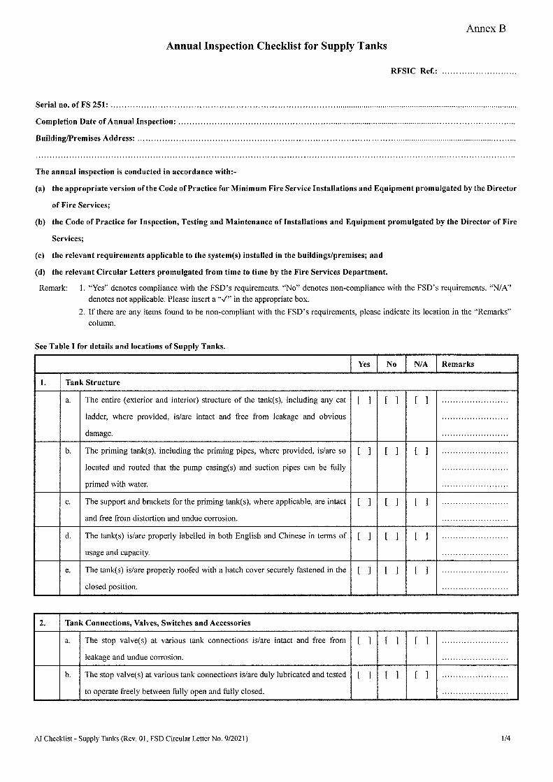
Annex B
Annual Inspection Checklist for Supply Tanks
RFSIC Ref.:
Serial no. of FS 251: ...................................................................................................................................................................... .
Completion Date of Annual Inspection: ..................................................................................................................................... .
Building/Premises Address: ................................................................................................................................................... .
The annual inspection is conducted in accordance with:-
(a) the appropriate version of the Code ofPractice for Minimum Fire Service Installations and Equipment promulgated by the Director
of Fire Services;
(b) the Code of Practice for Inspection, Testing and Maintenance of Installations and Equipment promulgated by the Director of Fire
Services;
(c) the relevant requirements applicable to the system(s) installed in the buildings/premises; and
(d) the relevant Circular Letters promulgated from time to time by the Fire Services Department.
Remark: I. "Yes" denotes compliance with the FSD's requirements. "No" denotes non-compliance with the FSD's requirements. "NIA" denotes not applicable. Please insert a" ✓" in the appropriate box.
2. If there are any items found to be non-compliant with the FSD's requirements, please indicate its location in the "Remarks"
column.
See Table I for details and locations of Supply Tanks.
Yes No NIA Remarks
1. Tank Structure
a. The entire (exterior and interior) structure of the tank(s), including any cat
ladder, where provided, is/are intact and free from leakage and obvious
damage.
[ ] [ ] [ l ........................
........................
........................
b. The priming tank(s), including the priming pipes, where provided, is/are so
located and routed that the pump casing(s) and suction pipes can be fully
primed with water.
[ ] [ ] [ ] ........................
························
························
c. The support and brackets for the priming tank(s), where applicable, are intact
and free from distortion and undue corrosion.
[ ] [ ] [ ] ........................
........................
d. The tank(s) is/are properly labelled in both English and Chinese in terms of
usage and capacity.
[ ] [ ] [ ] ........................
........................
e. The tank(s) is/are properly roofed with a hatch cover securely fastened in the
closed position.
[ ] [ ] [ ] ........................
........................
2. Tank Connections, Valves, Switches and Accessories
a. The stop valve(s) at various tank connections is/are intact and free from
leakage and undue corrosion.
[ ] [ ] [ ] ························
························ b. The stop valve(s) at various tank connections is/are duly lubricated and tested
to operate freely between fully open and fully closed.
[ ] [ ] [ ] ........................
........................
Al Checklist - Supply Tanks (Rev. 01, FSD Circular Letter No. 9/2021) 1/4

Annual Inspection Checklist for Supply Tanks
Yes No NIA Remarks
c. The stop valve(s) at various tank connections, where applicable, is/are
padlocked in the correct (fully open or fully closed) positions and labelled
"Normally Open '/$tlffl" or "Normally Closed '/$t~ffl" as appropriate.
[ ] [ ] [ ] ........................
........................
. .......................
d. The tank drain valve(s) is/are properly plugged/capped closed. [ ] [ ] [ ] ························
........................
e. The electrical monitoring switch(es) for stop valves at various tank
connections, where applicable, is/are intact, properly wired, protected by an
enclosure of appropriate IP rating, and tested to be in working order.
[ ] [ ] [ ] ........................
........................
........................
f The water level gauge(s), where provided, is/are intact and clearly indicate(s)
water levels with correct labelling.
[ ] [ ] [ ] ........................
························
g. The ball float valve(s), where provided, is/are intact and tested to operate
properly.
[ ] [ ] [ ] ........................
........................
h. The level switch(es) is/are intact, properly wired, and protected by an
enclosure of appropriate IP rating. For tanks fitted with more than one level
switch, the float cables/strings are prevented from swirling together.
[ ] [ ] [ ] ........................
························
························ I. The level switch(es) is/are tested to be in working order. [ ] [ ] [ ] ························
........................
j. The vortex inhibitor(s) or filter(s) fitted to the tank outlet pipe inside the
tank(s), where provided, is/are intact and free from blockage.
[ ] [ ] [ ] . .......................
. .......................
k. The foot valve(s), where provided, is/are tested to operate properly and free
from leakage and blockage.
[ ] [ ] [ ] ........................
........................
I. All piping connections inside the tank(s) are free from blockage. [ ] [ ] [ ] ........................
························ m. All tank external connections and pipes are intact, free from leakage and
properly supported.
[ ] [ ] [ ] ........................
························
3. Stored Water
a. The water inside the tank(s) is clean and free from debris and aquatic growth. [ ] [ ] [ ] ........................
........................
b. The water level(s) inside the tank(s) is/are not less than 90% of the required
storage capacity.
[ ] [ ] [ ] ························ ........................
c. The water level(s) inside the tank(s) stay(s) below the overflow pipe(s). [ ] [ ] [ ] ........................
........................
d. When the water level(s) drop(s) not more than 10% of the required storage
capacity, the ball float valve(s) or the transfer pump(s) as appropriate starts to
refill the tank(s).
[ ] [ ] [ ] ........................
........................
························
AI Checklist - Supply Tanks (Rev. 01, FSD Circular Letter No. 9/2021) 2/4

Annual Inspection Checklist for Supply Tanks
Yes No NIA Remarks
e. When the water level(s) cannot be maintained at more than 90% ofthe required
storage capacity, the low level alarm(s), where provided, at the pump control
panel and/or the F.S. control and indicating panel as appropriate, activate(s).
[ ] [ ] [ ] ························
························
························
f. Where applicable, when the water level in any priming tank cannot be
maintained at more than two-third of the required storage capacity, the pump
served by the priming tank starts running automatically.
[ ] [ ] [ ] ························
························
························
g. For tanks used for the combined storage of domestic ( e.g. potable/flushing)
and fire-fighting water, the maximum potential draw off by domestic services
in no way diminishes the supply for fire-fighting below the required reserve.
[ ] [ ] [ ] ························
························ ........................
Note:
This checklist specifies the minimum requirements for annual inspection for supply tanks. Incomplete inspections or inspections not
conducted in full accordance with this checklist shall not be recognised as properly completed annual inspections.
Authorized Signatory ofRFSIC:
(Name in Full) (Signature)
(Date)
Registered Fire Service Installation Contractor:
(FSD/RC No.) (Company Name)
( Company Stamp)
AI Checklist-Supply Tanks (Rev. 01, FSD Circular Letter No. 9/2021) 3/4

Annual Inspection Check.list for Supply Tanks
Table I
List of Supply Tanks
System Tank Location Building/Premises being Served Quantity Capacity (litres) Usage1 Type2 Remarks
Legend:
I. S: System water supply tank
J: Supply tank for jockey pump only
P: Priming tank
T: Transfer tank
2. RC: Reinforced-concrete
GRP: Glass-reinforced polyester/fibre-glass
M: Metal
AI Checklist - Supply Tanks (Rev. 0 I, FSD Circular Letter No. 9/2021) 4/4