Embed Size (px)
Citation preview

Operating manual 42/18�61 EN Rev. 02
TEIP 11 I/P signal converterwithout power stage

I/P signal converter TEIP 11without power stage
Operating manual
Document No. 42/18-61 EN
Release date 09.02Version 02
Manufacturer:
ABB Automation Products GmbHSchillerstrasse 7232425 Minden
Tel: +49 571 830-1494Fax: +49 571 830-1860
© Copyright 2002 by ABB Automation Products GmbHSubject to changes without notice.
This technical documentation is protected by copyright. Translating,photocopying and disseminating it in any form whatsoever - eveneditings or excerpts thereof - especially as reprint, photomechanical orelectronic reproduction or storage on data processing systems or net-works is not allowed without the permission of the copyright owner andnon-compliance will lead to both civil and criminal prosecution.

Table of contents
1 Safety and precautions ...................................................1
1.1 General safety instructions...........................................1
1.2 Requirements/conditions for safe use of explosion-proof TEIP 11 signal converters (type Doc. 900771)771) ........................................................2
2 General ..................................................................................5
2.1 Application and brief description.................................5
2.2 Deliverables....................................................................7
2.3 Scope of delivery ...........................................................7
2.4 CE compliance information ..........................................7
3 Mounting ...............................................................................8
3.1 Operating conditions at the installation site ...............8
3.2 Mounting the model with control room housing ........9
3.3 Mounting the model with aluminum or stainless steel field housing unit ...........................................................9
4 Connecting.........................................................................10
4.1 Electrical connection...................................................10
4.2 Pneumatic connection.................................................12
5 Commissioning ................................................................12
42/18-61 ENN i

6 Maintenance ......................................................................13
6.1 Checking / replacing the air filter ...............................13
6.2 Readjusting the signal converter ...............................14
7 Technical data...................................................................15
8 Dimensional drawings, connection diagrams ......21
ii 42/18-61 EN
1 Safety and precautionsy and precautions
1.1 General safety instructions
Correct and safe operation of the TEIP 11 or TEIP 11 Ex signal converter calls for appropriate transportation and stor-gnal converter calls for appropriate transportation and stor-age, expert installation and commissioning, correct operationand careful maintenance.
Only those persons familiar with the installation, commission-ing, operation and maintenance of this signal converter orsimilar instruments and who have the required qualificationare allowed to work on the device.
Observe:
• these operating instructions,
• the safety regulations and standards pertaining to the installation and operation of electrical systems,
• the standards, regulations and directives governing explosion protection, if explosion-proof devices are used.
The regulations, standards and directives referred to in theseoperating instructions are applicable in Germany. When usingthe signal converter in other countries, the national regula-tions, standards and directives applicable in the respectivecountry must be observed.
The signal converter has been manufactured and tested inaccordance with DIN VDE 0411 Part 1E 0411 Part 1
“Safety Requirements for Electronic Measuring Apparatuses”
and has been supplied in a safe condition.
Important instructions for your safety!your safety!Read and observe!
Warning
42/18-61 EN Safety and precautions 1
Prior to delivery, all devices have been tested for proper andsafe operation. These operating instructions contain warn-ings and cautions marked with . The instructions given inthese sections must be observed to retain the device in asafe condition and to ensure safe operation. Otherwise, per-sons can be endangered or the device itself or other equip-ment may be damaged or fail.
If you should need information that is not contained in thepresent operating instructions please do not hesitate to con-tact us.
1.2 Requirements/conditions for safe use of explosion-proof TEIP 11 signal converters P 11 signal converters (type Doc. 900771)
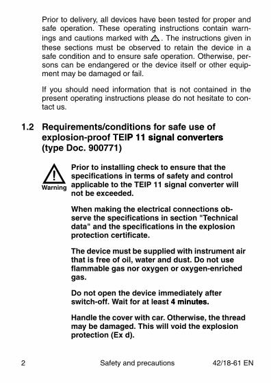
Prior to installing check to ensure that the specifications in terms of safety and control applicable to the TEIP 11 signal converter will not be exceeded.
When making the electrical connections ob-serve the specifications in section "Technical data" and the specifications in the explosion protection certificate.
The device must be supplied with instrument air that is free of oil, water and dust. Do not use flammable gas nor oxygen or oxygen-enriched gas.
Do not open the device immediately after switch-off. Wait for at least 4 minutes. 4 minutes.
Handle the cover with car. Otherwise, the thread may be damaged. This will void the explosion protection (Ex d).
Warning
2 Safety and precautions 42/18-61 EN

Specifications:
Input signal (0) 4…20 mA
Supply pressure, depending on type: 1.4 - 10 bar1.4 - 4 barother ranges depending on type
Exlusively use cable glands with full Ex-d approval for EEx-d operation.
Secure the cable and tube entries against turning and loosening by using security adhesive of medium strength.
If the signal converter is used at an ambient temperature above 60 °C (140°F) or below -20 °C 0 °C (140°F) or below -20 °C (-4 °F), use cable entries and cables approved for a service temperature corresponding to the maximum ambient temperature increased by 10 K or corresponding to the minimum ambient temperature, respectively.
Devices which – in the new state – comply with type of protection “Ex-ia” and "Ex-d" should not Ex-ia” and "Ex-d" should not be used intrinsically safe "Ex-ia" once they have been commissioned and used in an environment with type of protection “Ex-d”, since the electronics may have been damaged.
Warning
42/18-61 EN Safety and precautions 3
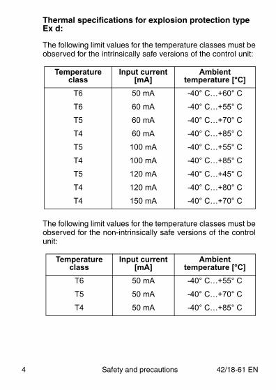
Thermal specifications for explosion protection type Ex d:
The following limit values for the temperature classes must beobserved for the intrinsically safe versions of the control unit:
The following limit values for the temperature classes must beobserved for the non-intrinsically safe versions of the controlunit:
Temperature class
Input current [mA]
Ambienttemperature [°C]
T6 50 mA -40° C…+60° C
T6 60 mA -40° C…+55° C
T5 60 mA -40° C…+70° C
T4 60 mA -40° C…+85° C
T5 100 mA -40° C…+55° C
T4 100 mA -40° C…+85° C
T5 120 mA -40° C…+45° C
T4 120 mA -40° C…+80° C
T4 150 mA -40° C…+70° C
Temperature class
Input current [mA]
Ambient temperature [°C]
T6 50 mA -40° C…+55° C
T5 50 mA -40° C…+70° C
T4 50 mA -40° C…+85° C
4 Safety and precautions 42/18-61 EN

2 General
2.1 Application and brief descriptionbrief description
The TEIP 11 or TEIP 11 Ex Signal Converter converts electri-cal into pneumatic standard signals, e.g. 4...20 mA into0.2...1 bar. It is, thus, a connecting link between the electrical/k between the electrical/electronic and the pneumatic systems. The patented signalconversion principle is based on the force balance method.Force balancing takes place at the lever arm which is pivotedwith a tension band at (9).
The coil (1) and yoke (2) generate a magnetic field in the airgap (3) which applies a force to the magnet (4) on the leverarm. The force changes in proportion to the current (input sig-nal) flowing through the coil (1).
On the other side of the lever arm a counterforce is appliedthrough the dynamic air pressure present at the air nozzle (6)
� � � � � � � � � �
�
� � � � � � � � � � � � � � � �
� � � � � � � � � � � � � � � � � � � � � � � � � � � �
� � � � � � � � � � � � � � � � � � � � � �
� �� �
Fig. 1 Functional diagram
42/18-61 EN General 5
and the flapper (5). The force is controlled in such a way thata balance of the two torques is achieved. If a torque imbal-ques is achieved. If a torque imbal-ance occurs, the lever arm is rotated. This rotation changesthe air gap between the nozzle (6) and the flapper (5) and,thus, the dynamic air pressure.
Air is permanently supplied to the nozzle (6) through thethrottle (7). The 1:1 converter stage (8) converts the dynamicair pressure into a 0.2...1 bar or 3...15 psi output signal. The3...15 psi output signal. Theair is fed in through the air filter (12) and fixed throttle (13).
Zero adjustment can be done on the tension band suspen-sion (9), and range adjustment on the potentiometer (10).
Special features of the TEIP 11 and TEIP 11 Ex signal con-verter are its relatively small dimensions and high operationalstability when submitted to shock and vibration. The stabilitywhen submitted to shock and vibration. The stabilityis due to the light weight (only 100 mg) of the moving system,which consists of the lever arm with the magnet (4) and theflapper (5).
The air filter (12) prevents malfunctions caused by pollutedair. Note that the filter capacity is only sufficient for collectingdirt that occurs occasionally (e.g. residual dirt in the air pipesat first use). It is no substitute for proper air conditioning.Some models are not equipped with an air filter (See “Mainte-nance” on page 13.)3.)
The pneumatic module was designed without an air powerstage, for the benefit of small dimensions and low cost. Dueto the reduced air capacity the signal converter can be usedfor controlling small volume systems, only.
6 General 42/18-61 EN
2.2 Deliverables
For details on the deliverable signal converter models andtheir accessories please refer to data sheet 10/18-0.11 EN,which also includes the catalog numbers of the individualitems.
2.3 Scope of delivery
Check the delivery (items and scope of delivery) immediately(items and scope of delivery) immediatelyupon arrival to see if it is in accordance with your order.
The following loose accessories are delivered with the unit asextra items:
• Mounting bracket for the aluminum or stainless steel fieldhousing unit (for wall or 2" pipe mounting)
• Cable entry for signal converter with “EEx d” explosionprotection
2.4 CE compliance information
We herewith declare that we are the manufacturer of theTEIP 11 signal converter and that the device meets the11 signal converter and that the device meets therequirements of the EC directive 89/336/EEC as of May 1989due to compliance with the following standards:
RFI suppressionEN 55011 as of 1991
EMI/RFI shieldingEN 50082-1 as of January 1991January 1991EN 50082-2 (PR) as of November 1993
The TEIP 11 signal converter meets the requirements of theEC directive for CE conformity marking.C directive for CE conformity marking.
42/18-61 EN General 7

3 Mountingg
3.1 Operating conditions at the installation site
Ambient temperature:40...+85 °C or -55...+85 °C, depending on the ordered model(see also additional information under ”Technical Data”)
Protection:IP 20 with control room housing unit
IP 65 65 with aluminum/stainless steel field housings
Explosion protection:
ATEX EEx ia or EEx d
CENELEC EEx ia or EEx d
BRITISH Standards Ex N
FM/CSA intrinsically safeM/CSA intrinsically safe
FM/CSA explosion proof
(see also additional information under ”Technical data”)
Mounting orientation:any orientation allowed
Prior to mounting check to ensure that the specifications in terms of safety and control applicable to the TEIP 11 signal converter TEIP 11 signal converter will not be exceeded.
Warning
8 Mounting 42/18-61 EN
3.2 Mounting the model with control room housing
This model is snap-mounted on a DIN top-hat rail.
The signal converter has a special mounting base. Due to itsuniversal design it is suitable for mounting to EN 50022 -50022 -35x7.5, EN 50045 - 15x5 and EN 50035 - G32 rails. Prefera-bly position the signal converter with the electrical connectiontowards the left hand side when mounting to a vertical rail,and upwards when mounting to a horizontal rail.
3.3 Mounting the model with aluminum or stainless steel field housing unit
This signal converter is available as a model for wall or 2“pipe mounting with 1/4 NPT pneumatic connections, and as amodel that can be directly flanged to pneumatic devices.
A stainless steel mounting bracket is available as a looseaccessory for the wall or 2“ pipe mounting model.
The second model is directly flanged to pneumatic devicesusing the two 6.7 mm mounting holes in the base. With this,the pneumatic connection of the air supply and output isachieved. Observe the position of the two 1.6 mm holes. TheObserve the position of the two 1.6 mm holes. Theair transitions have to be sealed on the pneumatic deviceside, e.g. by recesses with inserted O-ring seals.
Both housing types are environmentally ruggedized and aresuitable for outdoor installation without requiring further pro-tection.
Preferably position the unit such that the cablegland is oriented towards the bottom or horizon-tally to reduce moisture penetration.Caution
42/18-61 EN Mounting 9

4 Connecting
4.1 Electrical connectionWhen making the electrical installation observe:
• the relevant regulations and safety standards pertaining to the installation and operation of electrical systems.
• the additional regulations, standards and directives governing the installation and operation of explosion-proof systems, if explosion-proof devices are used.
• the specifications in “Technial Data”. For explosion-proof devices also observe the specifications in the explosion protection certificate.
Do not run signal cables close to power lines. Power lines produce interference in their near vicinity which impairs the signals transmitted on the line.
Exclusively use cable glands with full Ex-d approval for EEx d operation (partly approved (partly approved cable glands labeled “U” are NOT sufficient).
Fix the screwed-in Ex-d cable gland with glue to secure it against loosening. Loctite 242/243 or /243 or similar glues are suitable.
Warning
10 Connecting 42/18-61 EN

A 2-pole screw-terminal for cables with a max. cross-sec-tional area of 2.5 mm2 is used for making the electrical con-nection. Do not reverse polarity when connecting the cable.
The screw-terminal of the control room housing unit islocated on the side of the device, and the one of the fieldhousing unit is accommodated inside the housing, i.e. thefield housing must be opened for connecting the cable.
Cable entries of different types are provided:
standard or EEx ia or Ex N Pg 13.5 cable gland
EEx d M 20x1.51 thread
FM/CSA ”intrinsically safe” 1/2 NPT threadT threador ”explosion proof”
1. a cable gland with Ex certificate INIEX 88B. 103. 748 can be delivered as a loose part for EEx d (see “Accessories” in Section “Ordering information” of data sheet 10/18-0.11 EN).
42/18-61 EN Connecting 11
4.2 Pneumatic connection
The control room housing has external 1/8 NPT holes forconnecting the air pipes (for air supply and output). Themodel with field housing for wall or 2“ pipe mounting hasexternal 1/4 NPT holes.
The recommended pipe dimension is 6 x 1 mm. Dust, splin-ters or any other particles must be blown off the pipe beforeconnecting. The connections for air supply and output aremarked accordingly.
Flange-mounting the signal converter model for direct attach-verter model for direct attach-ment to a pneumatic device at the same time establishes thepneumatic connection. We recommend to insert filters (sin-tered disks) into the air ducts near the signal converter. Expe-rience has shown that residual dirt in the air ducts or outerpipes may lead to malfunctions.
The supply pressure for the signal converter has to be set to1.4...10 bar, as required.
5 Commissioning
The signal converter is ready for operation immediately afterinstallation and connection. No further adjustment is required.
The supply air must be free of oil, water anddust in accordance with DIN/ISO 8573-1,73-1,Class 3. The dew point must be 10 K below theminimum operating temperature.
Caution
12 Commissioning 42/18-61 EN
6 Maintenance
The signal converter is maintenance-free. Note that the sup-plied instrument air must be free of oil, water and dustaccording to DIN/ISO 8573-1 to ensure trouble-free opera-tion.
It is recommended to check on a regular basis the built-in tex-tile filter (if existing) for the degree of pollution and the signal(if existing) for the degree of pollution and the signalconversion to see if the values are still within the tolerance.
6.1 Checking / replacing the air filter
The air filter only exists for models with field housing for wallmounting or 2“ pipe mounting.
If the supply air for the signal converter has not been condi-tioned properly (supplied air must be clean and dry in accor-dance with DIN/ISO 8573-13-1), the built-in textile filter protectsthe sensitive air nozzles and throttles from being obstructedwith dirt. However, the filter capacity suffices only for occa-sionally collecting little dirt. In case of a pollution over alonger time the filter gets choked.
To check the degree of filter pollution first open the screw andthen remove the filter element using tweezers (see Fig. 2 onpage 14). Spare filter elements are available from us undercatalog number 7942511. 942511.
The signal converter is ready to operate immediately after thefilter element has been replaced. No further measures - likereadjustment - are required.
Switch off the air supply before replacing thefilter element.
Warning
42/18-61 EN Maintenance 13

6.2 Readjusting the signal converterdjusting the signal converter
The signal converters aredelivered in an adjustedcondition.
After longer operating peri-ods, however, the tolerancelimits may be exceededdue to aging or drift. Thiscan be eliminated by re-adjustment.
The signal converter can be readjusted by using the twoadjustment screws marked ”> o <“ for zero (10) and ”<->”for span (16). When using a field housing unit first remove the6). When using a field housing unit first remove thecover to access the screws.
� � � � � � � �
� � � � � � � � � � � � �
� � � � � � � � �
� � � � � � �� � !
Fig. 2 Air filter (sectional drawing)(sectional drawing)�
16 10
Fig. 3 Adjustment screws
14 Maintenance 42/18-61 EN
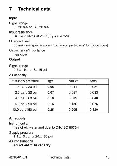
7 Technical data
Input
Signal range0...20 mA or 4...20 mA
Input resistanceRi = 260 ohms at 20 °C, Tk + 0.4 %/K%/K
Overload limit30 mA (see specifications “Explosion protection” for Ex devices)
Capacitance/Inductancenegligible
Output
Signal range0.2...1 bar or 3...15 psibar or 3...15 psi
Air capacity
Air supply
Instrument airfree of oil, water and dust to DIN/ISO 8573-1
Supply pressure1.4...10 bar or 20...150 psi
Air consumptionequivalent to air capacityvalent to air capacity
at supply pressure kg/h Nm3/h scfm
1.4 bar / 20 psi 0.05 0.041 0.024
2.0 bar / 30 psi 0.07 0.057 0.033
4.0 bar / 60 psi 0.10 0.082 0.048
6.0 bar / 90 psi 0.16 0.130 0.076
10.0 bar /150 psi 0.25 0.205 0.120
42/18-61 EN Technical data 15
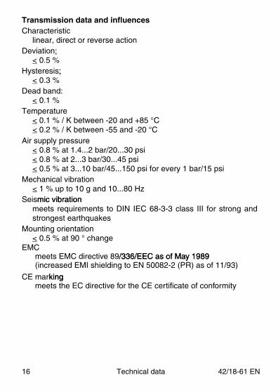
Transmission data and influencesCharacteristic
linear, direct or reverse actionDeviation:
< 0.5 %Hysteresis:
< 0.3 %Dead band:
< 0.1 %Temperature
< 0.1 % / K between -20 and +85 °C< 0.2 % / K between -55 and -20 °C
Air supply pressure< 0.8 % at 1.4...2 bar/20...30 psi< 0.8 % at 2...3 bar/30...45 psi< 0.5 % at 3...10 bar/45...150 psi for every 1 bar/15 psi
Mechanical vibration< 1 % up to 10 g and 10...80 Hz
Seismic vibrationmic vibrationmeets requirements to DIN IEC 68-3-3 class III for strong andstrongest earthquakes
Mounting orientation< 0.5 % at 90 ° change
EMCmeets EMC directive 89/336/EEC as of May 1989 /336/EEC as of May 1989 (increased EMI shielding to EN 50082-2 (PR) as of 11/93)
CE markingkingmeets the EC directive for the CE certificate of conformity
16 Technical data 42/18-61 EN

Environmental capabilitiesClimate class
GPF or FPF to DIN 40040
Temperature-40....+85 °C or -55...85 °C 5 °C or -55...85 °C
Relative humidity75 % average, 95 % short-time, non-condensing
Observe the following limits:
1. For operation in hazardous areas observe the max. x. temperature limits specified under ”Explosion protection”.
2. For operation in hazardous areas and temperatures below -20 °C observe the special mounting conditions specified in the explosion protection certificate.
Explosion protection
ATEX, intrinsically safe 2G EEx ia IIC T4/T5/T6, Tüv 1487 x/T5/T6, Tüv 1487 x
ATEX, flameproof enclosure, EEx d IIC T4/T5/T6
CENELEC, intrinsically safe (all models))EEx ia IIC T4/T5/T6, PTB No. Ex-93.C.2104X
CENELEC, flameproof (only for field housing units)using units)EEx d IIC T4/T5/T6, BVS No. 90.C.2016X
Observe the following limits for the temperature classesllowing limits for the temperature classes
Temperature class Max. short circuit current Max. ambient temperature
T6T6T5T5T5T4T4T4T4
50 mA60 mA60 mA
100 mA120 mA60 mA
100 mA120 mA150 mA
60 °C55 °C70 °C55 °C45 °C85 °C85 °C80 °C70 °C
42/18-61 EN Technical data 17

BRITISH Standards (only for ”field housing” unit)
Ex N II T6 for Zone 2, Certificate SSA 914012A 914012
FM “intrinsically safe” (only for ”control room housing” units)I.S.: CL I / Div 1 / Grp A B C DGrp A B C DN.I.: CL I / Div 2 / Grp A B C D
FM “intrinsically safe” (only for ” field housing” units)I.S.: CL I-II-II / Div 1 / Grp A B C D E F G1 / Grp A B C D E F GN.I.: CL I / Div 2 / Grp A B CS.: CL II / Div 2 / Grp GS.: CL III / Div 2
FM “explosion proof” (only for ”field housing” units)ts)X.P.: CL I /Div 1 / Grp B C DD.I.P.: CL II II / Div 1 Grp E F G
CSA “intrinsically safe” (only for ”control room housing“ units)I.S.: CL I / Div 1 / Grp A B C D
CL I / Div 2 / Grp A B C D2 / Grp A B C D
CSA “intrinsically safe” (only for ”field housing” units)I.S.: CL I / Div 1 / Grp A B C D
CL II / Div 1 / Grp E F GCL IIICL I / Div 2 / Grp A B C DCL II / Div 2 / Grp E F G
CSA “explosion proof” (only for ”field housing” units)X.P.: CL I / Div 1 / Grp B C G
CL II / Div 1 / Grp E F G
Other explosion protection certificates on request
18 Technical data 42/18-61 EN

Control room housing unit
Material/protectionAluminium housing, IP 20, with plastic capg, IP 20, with plastic cap
MountingRail EN 50022 - 35 x 7.5
EN 50035 - G 32 EN 50045 - 15 x 5
Electrical connection2-pole screw terminal for 2.5 mm2
Pneumatic connectiontwo 1/8 NPT threads for air supply and outputT threads for air supply and output
Mounting orientation: any
Weight0.25 kg
Dimensionssee dimensional drawing
Aluminium/stainless steel field housing unitMaterial/protection
Aluminium or stainless steel housing, IP 65(aluminum housing with two-component varnish,color: blue (RAL 5010))
MountingWall mounting or 2” pipe mounting with separate stainless steel mounting bracket ortwo 6.7 mm holes at add-on module for OEM applicationdd-on module for OEM application
Electrical connection2-pole screw terminal for 2.5 mm2 in housingwith PG 13.5 cable gland
for ”standard”, “CENELEC intrinsically safe”//ATEX EEx d and for ”BRITISH Standards Ex N”
42/18-61 EN Technical data 19

Electrical connection (continued from previous page)with M 20x1.5 thread.5 thread
for “CENELEC EEx d”/ATEX EEx d(on request cable gland with Ex d certificate as accessory)
with 1/2 NPT thread for cable entryfor FM/CSA/ATEX EEx d
Pneumatic connectiontwo 1/4 NPT threads for air supply and outputortwo lateral 1.6 mm holes on add-on module6 mm holes on add-on module
Mounting orientationany
Weight0.62 kg with aluminium housing1.20 kg with stainless steel housing
Dimensionssee dimensional drawing
Spare partsExcept for the textile filter, the signal converter is wear free anddoes not require maintenance. Therefore, filter elements are theonly spare parts that should be kept on stock (refer to Sectionbe kept on stock (refer to Section“Maintenance” for the catalog no.)
20 Technical data 42/18-61 EN

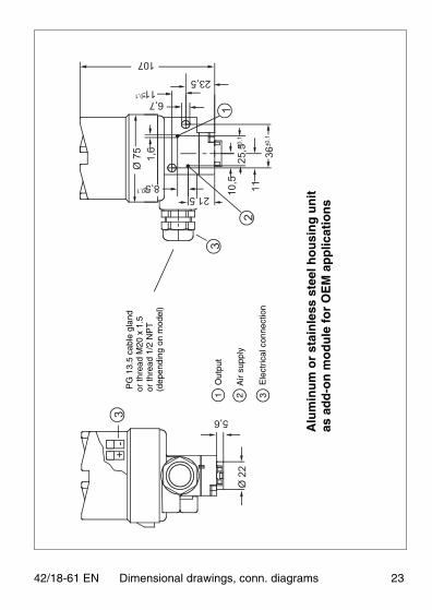
8 Dimensional drawings, conn. diagrams, conn. diagrams
��
"��#�
�
��
��
��
��
"��#�
�
��
��
��#��
�� �
1 2 3
Out
put
Air
supp
ly
Ele
ctric
al c
onne
ctio
ns
Co
ntr
ol r
oo
m h
ou
sin
g u
nit
Mo
un
tin
g b
rack
et
42/18-61 EN Dimensional drawings, conn. diagramswings, conn. diagrams 21

�
�
�
�
�
���
��
���$��%
���
"��
��
��
��
�
�
1 2 3
Out
put
Air
supp
ly
Ele
ctric
al c
onne
ctio
ns
Alu
min
um
or
stai
nle
ss s
teel
Pro
file
sh
eet
met
alfo
r w
all m
ou
nti
ng
fiel
d h
ou
sin
g u
nit
for
wal
l or
2“ p
ipe
mo
un
tin
g
PG
13.
5 ca
ble
glan
dor
thre
ad M
20 x
1.5
or th
read
1/2
NP
T(d
epen
ding
on
mod
el)
22 Dimensional drawings, conn. diagrams 42/18-61 EN
�
�#�
"��
"���
�#
#��$�#�
��#�
��#� ��#�
��#�$
�#�
��
���$�
#�
��
���$�#�
$��%
�
�
�
�#�
1 2 3
Out
put
Air
supp
ly
Ele
ctric
al c
onne
ctio
n
PG
13.
5 ca
ble
glan
dor
thre
ad M
20 x
1.5
or th
read
1/2
NP
T(d
epen
ding
on
mod
el)
Alu
min
um
or
stai
nle
ss s
teel
ho
usi
ng
un
itas
ad
d-o
n m
od
ule
fo
r O
EM
ap
plic
atio
ns
42/18-61 EN Dimensional drawings, conn. diagrams 23

ABB Automation Products GmbHSchillerstraße 7232425 Minden, GERMANYTel: +49 571 830�1494Fax: +49 571 830�1860
Subject to technical changes.This technical documentation is protected by copyright. Translating,photocopying and disseminating it in any form whatsoever - even edit-ings or excerpts thereof - especially as reprint, photomechanical or elec-tronic reproduction or storage on data processing systems or networksis not allowed without the permission of the copyright owner and non-compliance will lead to both civil and criminal prosecution.
Subject to technical changesPrinted in the Fed. Rep. of Germany
42/18�61 EN Rev. 02Edition 09.02


![1. Index [eko-eu.com] · EKO INSTRUMENTS CO., LTD. 4-20mA Signal Converter MC-11 Instruction Manual Ver.4 Pg. 6 4. Introduction 4-1. Main Functions Pyranometer Signal Converter MC-11](https://img.pdfslide.us/doc/110x75/5f37a3a97f20d670052cfa52/1-index-eko-eucom-eko-instruments-co-ltd-4-20ma-signal-converter-mc-11-instruction.jpg)