Embed Size (px)
Citation preview

Carburetor Identification,Troubleshooting and Service
ENGINES TRANSMISSIONS&
TecumsehPower
Service Dealer’s and Technician’s Training and Informational Series
TECUMSEHPOWER
I
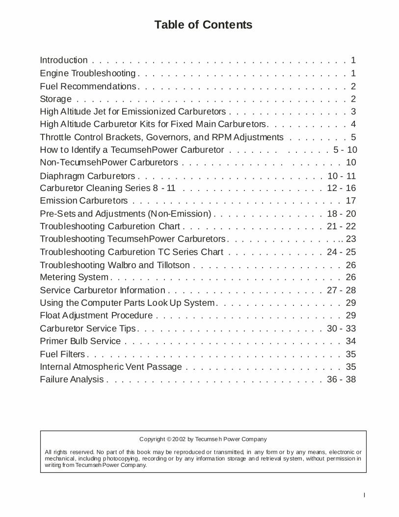
Table of Contents
Introduction . . . . . . . . . . . . . . . . . . . . . . . . . . . . . . . . . . 1
Engine Troubleshooting . . . . . . . . . . . . . . . . . . . . . . . . . . . . 1
Fuel Recommendations . . . . . . . . . . . . . . . . . . . . . . . . . . . . 2Storage . . . . . . . . . . . . . . . . . . . . . . . . . . . . . . . . . . . . 2High Altitude Jet for Emissionized Carburetors . . . . . . . . . . . . . . . . 3
How to Identify a TecumsehPower Carburetor . . . . . . . . . . . . . 5 - 10Non-TecumsehPower Carburetors . . . . . . . . . . . . . . . . . . . . . 10
Diaphragm Carburetors
Troubleshooting Carburetion Chart . . . . . . . . . . . . . . . . . . . 21 - 22Troubleshooting TecumsehPower Carburetors . . . . . . . . . . . . . . . . .. 23
Troubleshooting Carburetion TC Series Chart . . . . . . . . . . . . . 24 - 25
Troubleshooting Walbro and Tillotson . . . . . . . . . . . . . . . . . . . . 26Metering System . . . . . . . . . . . . . . . . . . . . . . . . . . . . . . . 26
Service Carburetor Information . . . . . . . . . . . . . . . . . . . . . 27 - 28Using the Computer Parts Look Up System. . . . . . . . . . . . . . . . . 29Float Adjustment Procedure . . . . . . . . . . . . . . . . . . . . . . . . . 29
Carburetor Service Tips . . . . . . . . . . . . . . . . . . . . . . . . . 30 - 33Primer Bulb Service . . . . . . . . . . . . . . . . . . . . . . . . . . . . . 34
Fuel Filters . . . . . . . . . . . . . . . . . . . . . . . . . . . . . . . . . . 35Internal Atmospheric Vent Passage . . . . . . . . . . . . . . . . . . . . . 35Failure Analysis . . . . . . . . . . . . . . . . . . . . . . . . . . . . . 36 - 38
Thrott le Control Brackets, Governors, and RPM Adjustments . . . . . . . . 5
Carburetor Cleaning Series 8 - 11 . . . . . . . . . . . . . . . . . . . 12 - 16
Pre-Sets and Adjustments (Non-Emission) . . . . . . . . . . . . . . . 18 - 20
High Altitude Carburetor Kits for Fixed Main Carburetors. . . . . . . . . . . 4
. . . . . . . . . . . . . . . . . . . . . . . . . 10 - 11
Emission Carburetors . . . . . . . . . . . . . . . . . . . . . . . . . . . . 17
Copyright © 20 02 by Tecumse h Power Company
All rights reserved. No part of this book may be reproduced or t ransmitted, in any form or b y any means, electronic or mechanical, including p hotocopying, recording or by any informa tion storage an d retrieval system, without permission in writing from Tecumseh Power Comp any.
INTRODUCTION
PLEASE DO:
DO NOT:
ENGINE TROUBLESHOOTING
This troubleshooting book is designed as a quick reference for carburetion problems and an aid in identifying failures and their possible causes. It also directs the user to other publications and printed material that assist in properly resolving problems or making adjustments not related to carburetion but could affect carburetion.
Listed below are some basic DO’S and DON’TS to be followed when making carburetor repairs.
Follow all instructions carefully.
Use new service replacement screws (650506 Torx 8) for the choke and throttle shutters (screws are treated with a dry-type adhesive to secure them in place).
Use TecumsehPower float tool 670377 or an 11/64 drill bit to set the proper float height. Remove the bowl gasket and measure from the casting surface. The gasket should be replaced or poor starting may result.
Use only genuine TecumsehPower service parts.
Remove all welch plugs, o-rings and non-metallic main nozzles before cleaning carburetor in cleaner.
Use drill bits to clean passages.Enlarge passages.Soak carburetor in a cleaner over 30 minutes.Reuse original choke and throttle shutter screws.Interchange bowl nuts.Reuse gaskets and “O” rings.
When troubleshooting a carburetor, other areas such as valves, fuel tank venting or gaskets should not be overlooked. The carburetor is dependent on the proper operation of the engine to do its job. The first step in troubleshooting is to determine if you have a carburetor or an engine problem.
In order for the engine to operate properly, the following items need to be checked first:
1. Make sure there is a sufficient amount of clean, fresh fuel in the tank.
2. Check spark plug for proper reach, gap and condition. Replace, if needed, or in question. Perform an ignition test using spark tester part number 670366 to assure that you have a crisp spark.
NOTEOn older point ignitions models check for proper ignition timing according to the Technician's handbook.
3. Check for fuel flow restrictions into the carburetor. Deteriorated fuel line, and fuel cap venting are some of the more common restrictions. TecumsehPower uses a stainless steel 75 micron filter screen molded into most tanks. It is extremely rare for this area to become restricted and should be checked last.
4. Check compression by first disconnecting the spark plug lead and ground it to prevent start-up. Next, turn the engine over by hand. A definite resistance should be noticed on the compression stroke. Using a cylinder leak down tester is also possible.
After these basic checks have been performed and you are satisfied with the engine's condition, attempt to start it. If it does not start, remove the spark plug and check its condition. If it is dry, you can assume there is a problem with the carburetor or the fuel system. Continue by troubleshooting the carburetor.
1
FUEL RECOMMENDATIONS
STORAGE
FUELTecumsehPower strongly recommends the use of fresh clean unleaded regular gasoline in all engines. Unleaded gasoline burns cleaner, extends engine life and promotes better starting by reducing build-up of combustion chamber deposits. Reformulated fuels containing no more than 10% Ethanol, 15% MTBE, 15% ETBE or premium gasoline can be used if unleaded regular gasoline is not available. Leaded fuel may be used in countries where unleaded fuel is not available. NEVER USE FUEL CONTAINING METHANOL.
Gasoline (Fuel) vapors are highly flammable and can explode. Fuel vapors can spread and be ignited by a spark or flame many feet away from the engine. To prevent injury or death from fuel fires, follow these instructions:
• Never store the engine with fuel in the fuel tank inside a building with potential sources of ignition such as hot water and space heaters, clothes dryer, electric motors, etc.
Gasoline can become unstable in less than 30 days and form deposits that can impede proper fuel flow and engine operation. To prevent deposits from forming, all gasoline must be removed from the fuel tank and the carburetor. An acceptable alternative to removing all gasoline is adding a fuel stabilizer such as TecumsehPower Ultra-Fresh part number 730245 to the gasoline. Fuel stabilizer should be added to the fuel tank or storage container. Always follow the mix ratio found on the stabilizer container. Run the engine at least 10 minutes after adding the stabilizer to allow it to reach the carburetor.
Draining the Fuel System
Drain the fuel into an approved container outdoors, and away from any open flame or combustion source. Be sure the engine is cool.
NOTEIf gasohol has been used, put a small amount of unleaded gasoline into fuel tank and repeat preceding instructions, then run engine until fuel is used up.
Oil Cylinder Bore
1. Remove the spark plug wire from the spark plug. NOTE: Always ground the plug wire when disconnected. Pull the starter handle slowly until resistance is felt from compression pressure, then stop. Slowly release starter tension to prevent the engine from reversing due to compression pressure.
2. Remove the spark plug, squirt 1/2 ounce (15 ml.) of clean engine oil into the spark plug hole.
3. Cover the spark plug hole with a shop towel and crank the engine over slowly, several times.
4. Replace the spark plug and tighten. Pull the starter handle as performed in step #1. The piston position blocks the cylinder ports on 2 cycle engines or closes the valves on 4 cycle engines, preventing air from entering and oil from leaving the cylinder bore during storage.
5. Re-connect the spark plug wire on the spark plug.
IF THE ENGINE IS TO BE UNUSED FOR 30 DAYS OR MORE
Do not attempt to pour fuel from engine or siphon fuel by mouth. Empty fuel tank by using a commercially available suction device designed for use with gasoline. Then run the engine until any remaining fuel is consumed. Doing so may result in death or serious injury.
WARNING
2
WARNING
CAUTION
3
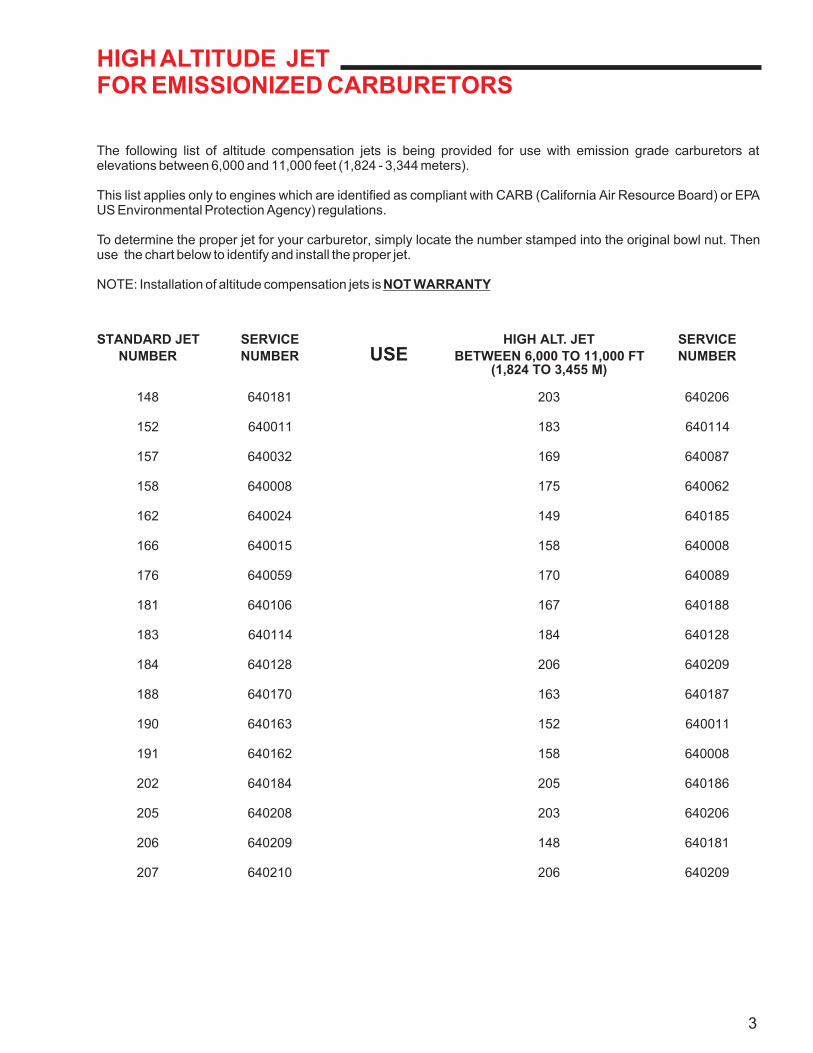
HIGH ALTITUDE JETFOR EMISSIONIZED CARBURETORS
The following list of altitude compensation jets is being provided for use with emission grade carburetors at elevations between 6,000 and 11,000 feet (1,824 - 3,344 meters).
This list applies only to engines which are identified as compliant with CARB (California Air Resource Board) or EPA US Environmental Protection Agency) regulations.
To determine the proper jet for your carburetor, simply locate the number stamped into the original bowl nut. Then use the chart below to identify and install the proper jet.
NOTE: Installation of altitude compensation jets is NOT WARRANTY
STANDARD JET SERVICE HIGH ALT. JET SERVICE
NUMBER NUMBER USE BETWEEN 6,000 TO 11,000 FT NUMBER(1,824 TO 3,455 M)
148 640181 203 640206
152 640011 183 640114
157 640032 169 640087
158 640008 175 640062
162 640024 149 640185
166 640015 158 640008
176 640059 170 640089
181 640106 167 640188
183 640114 184 640128
184 640128 206 640209
188 640170 163 640187
190 640163 152 640011
191 640162 158 640008
202 640184 205 640186
205 640208 203 640206
206 640209 148 640181
207 640210 206 640209
4
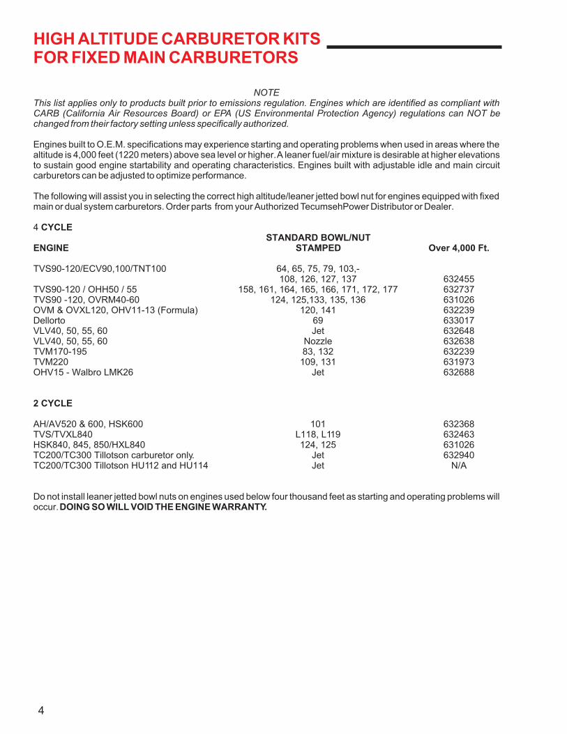
HIGH ALTITUDE CARBURETOR KITSFOR FIXED MAIN CARBURETORS
NOTEThis list applies only to products built prior to emissions regulation. Engines which are identified as compliant with CARB (California Air Resources Board) or EPA (US Environmental Protection Agency) regulations can NOT be changed from their factory setting unless specifically authorized.
Engines built to O.E.M. specifications may experience starting and operating problems when used in areas where the altitude is 4,000 feet (1220 meters) above sea level or higher. A leaner fuel/air mixture is desirable at higher elevations to sustain good engine startability and operating characteristics. Engines built with adjustable idle and main circuit carburetors can be adjusted to optimize performance.
The following will assist you in selecting the correct high altitude/leaner jetted bowl nut for engines equipped with fixed main or dual system carburetors. Order parts from your Authorized TecumsehPower Distributor or Dealer.
4 CYCLESTANDARD BOWL/NUT
ENGINE STAMPED Over 4,000 Ft.
TVS90-120/ECV90,100/TNT100 64, 65, 75, 79, 103,-108, 126, 127, 137 632455
TVS90-120 / OHH50 / 55 158, 161, 164, 165, 166, 171, 172, 177 632737TVS90 -120, OVRM40-60 124, 125,133, 135, 136 631026OVM & OVXL120, OHV11-13 (Formula) 120, 141 632239Dellorto 69 633017VLV40, 50, 55, 60 Jet 632648VLV40, 50, 55, 60 Nozzle 632638TVM170-195 83, 132 632239TVM220 109, 131 631973OHV15 - Walbro LMK26 Jet 632688
2 CYCLE
AH/AV520 & 600, HSK600 101 632368TVS/TVXL840 L118, L119 632463HSK840, 845, 850/HXL840 124, 125 631026TC200/TC300 Tillotson carburetor only. Jet 632940TC200/TC300 Tillotson HU112 and HU114 Jet N/A
Do not install leaner jetted bowl nuts on engines used below four thousand feet as starting and operating problems will occur. DOING SO WILL VOID THE ENGINE WARRANTY.
THROTTLE CONTROL BRACKETS,GOVERNORS AND RPM ADJUSTMENTS
HOW TO IDENTIFY A TecumsehPower CARBURETOR
Before adjusting any mixture screws, reset the screws to the recommended carburetor presets. Check for proper governor adjustments as outlined in the appropriate Technician's Handbook. Identify the locations of your high speed and low speed RPM adjustment screws. Check to make sure that the throttle control brackets are adjusted properly to allow for full choke. Always make sure that normal maintenance procedures (ie., oil, fuel, air cleaner, etc.) have been checked. Consult microfiche card #30, the computer parts look up system or Service Bulletin #107 for C.P.S.C. specifications to determine the proper RPM settings. Start the engine, allow it to warm up, the carburetor can then be adjusted for optimum performance by using the information outlined in this book. Now the low and high speed screws can be adjusted to the recommended RPM's.
TecumsehPower has a variety of carburetors. To help identify these carburetors here are some simple procedures to follow.
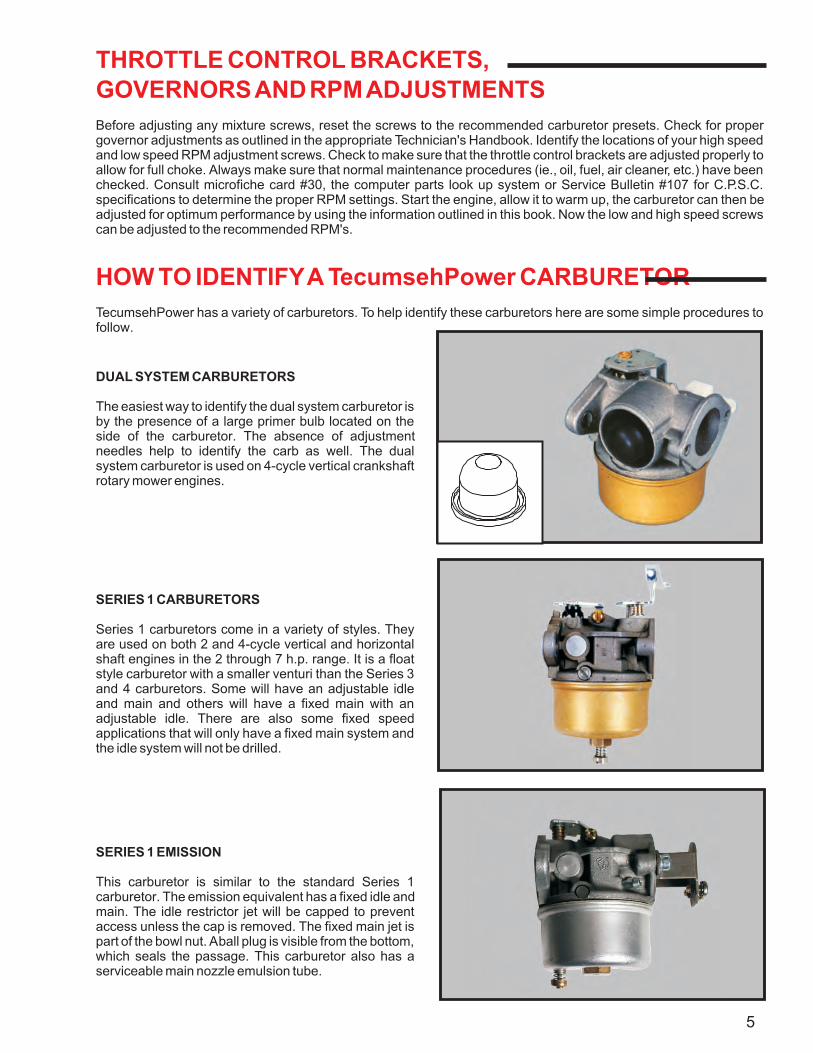
DUAL SYSTEM CARBURETORS
The easiest way to identify the dual system carburetor is by the presence of a large primer bulb located on the side of the carburetor. The absence of adjustment needles help to identify the carb as well. The dual system carburetor is used on 4-cycle vertical crankshaft rotary mower engines.
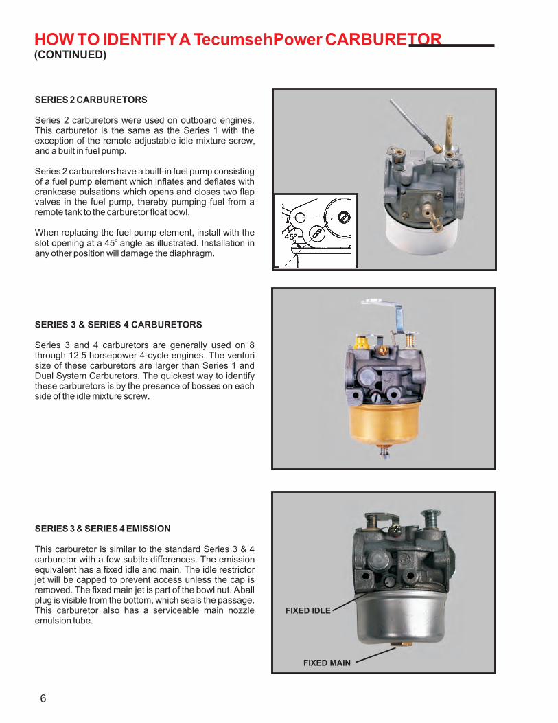
SERIES 1 CARBURETORS
Series 1 carburetors come in a variety of styles. They are used on both 2 and 4-cycle vertical and horizontal shaft engines in the 2 through 7 h.p. range. It is a float style carburetor with a smaller venturi than the Series 3 and 4 carburetors. Some will have an adjustable idle and main and others will have a fixed main with an adjustable idle. There are also some fixed speed applications that will only have a fixed main system and the idle system will not be drilled.
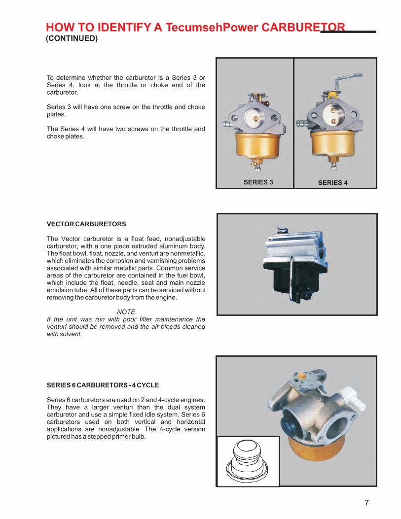
SERIES 1 EMISSION
This carburetor is similar to the standard Series 1 carburetor. The emission equivalent has a fixed idle and main. The idle restrictor jet will be capped to prevent access unless the cap is removed. The fixed main jet is part of the bowl nut. A ball plug is visible from the bottom, which seals the passage. This carburetor also has a serviceable main nozzle emulsion tube.
5
HOW TO IDENTIFY A TecumsehPower CARBURETOR(CONTINUED)
SERIES 2 CARBURETORS
Series 2 carburetors were used on outboard engines. This carburetor is the same as the Series 1 with the exception of the remote adjustable idle mixture screw, and a built in fuel pump.
Series 2 carburetors have a built-in fuel pump consisting of a fuel pump element which inflates and deflates with crankcase pulsations which opens and closes two flap valves in the fuel pump, thereby pumping fuel from a remote tank to the carburetor float bowl.
When replacing the fuel pump element, install with the oslot opening at a 45 angle as illustrated. Installation in
any other position will damage the diaphragm.
SERIES 3 & SERIES 4 CARBURETORS
Series 3 and 4 carburetors are generally used on 8 through 12.5 horsepower 4-cycle engines. The venturi size of these carburetors are larger than Series 1 and Dual System Carburetors. The quickest way to identify these carburetors is by the presence of bosses on each side of the idle mixture screw.
SERIES 3 & SERIES 4 EMISSION
This carburetor is similar to the standard Series 3 & 4 carburetor with a few subtle differences. The emission equivalent has a fixed idle and main. The idle restrictor jet will be capped to prevent access unless the cap is removed. The fixed main jet is part of the bowl nut. A ball plug is visible from the bottom, which seals the passage. This carburetor also has a serviceable main nozzle emulsion tube.
6
FIXED IDLE
FIXED MAIN
HOW TO IDENTIFY A TecumsehPower CARBURETOR(CONTINUED)
To determine whether the carburetor is a Series 3 or Series 4, look at the throttle or choke end of the carburetor.
Series 3 will have one screw on the throttle and choke plates.
The Series 4 will have two screws on the throttle and choke plates.
SERIES 6 CARBURETORS - 4 CYCLE
Series 6 carburetors are used on 2 and 4-cycle engines. They have a larger venturi than the dual system carburetor and use a simple fixed idle system. Series 6 carburetors used on both vertical and horizontal applications are nonadjustable. The 4-cycle version pictured has a stepped primer bulb.
VECTOR CARBURETORS
The Vector carburetor is a float feed, nonadjustable carburetor, with a one piece extruded aluminum body. The float bowl, float, nozzle, and venturi are nonmetallic, which eliminates the corrosion and varnishing problems associated with similar metallic parts. Common service areas of the carburetor are contained in the fuel bowl, which include the float, needle, seat and main nozzle emulsion tube. All of these parts can be serviced without removing the carburetor body from the engine.
NOTEIf the unit was run with poor filter maintenance the venturi should be removed and the air bleeds cleaned with solvent.
7
SERIES 3 SERIES 4
HOW TO IDENTIFY A TecumsehPower CARBURETOR(CONTINUED)
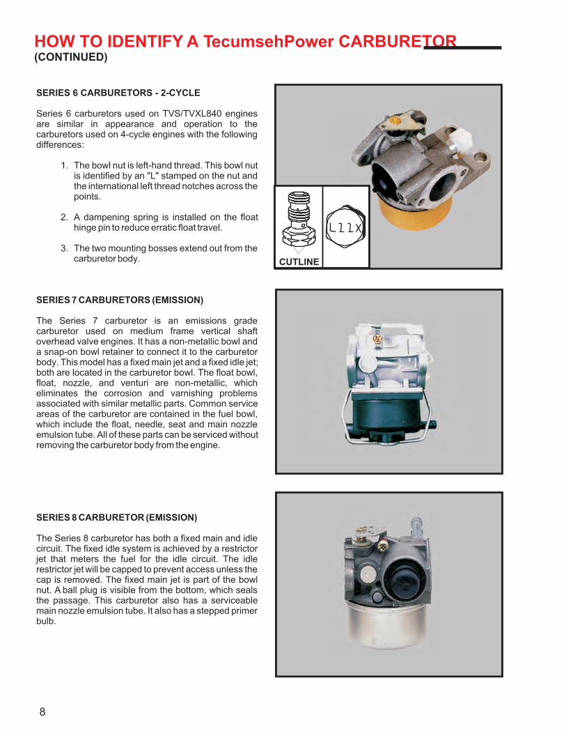
SERIES 6 CARBURETORS - 2-CYCLE
Series 6 carburetors used on TVS/TVXL840 engines are similar in appearance and operation to the carburetors used on 4-cycle engines with the following differences:
1. The bowl nut is left-hand thread. This bowl nut is identified by an "L" stamped on the nut and the international left thread notches across the points.
2. A dampening spring is installed on the float hinge pin to reduce erratic float travel.
3. The two mounting bosses extend out from the carburetor body.
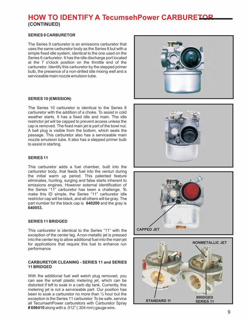
SERIES 7 CARBURETORS (EMISSION)
The Series 7 carburetor is an emissions grade carburetor used on medium frame vertical shaft overhead valve engines. It has a non-metallic bowl and a snap-on bowl retainer to connect it to the carburetor body. This model has a fixed main jet and a fixed idle jet; both are located in the carburetor bowl. The float bowl, float, nozzle, and venturi are non-metallic, which eliminates the corrosion and varnishing problems associated with similar metallic parts. Common service areas of the carburetor are contained in the fuel bowl, which include the float, needle, seat and main nozzle emulsion tube. All of these parts can be serviced without removing the carburetor body from the engine.
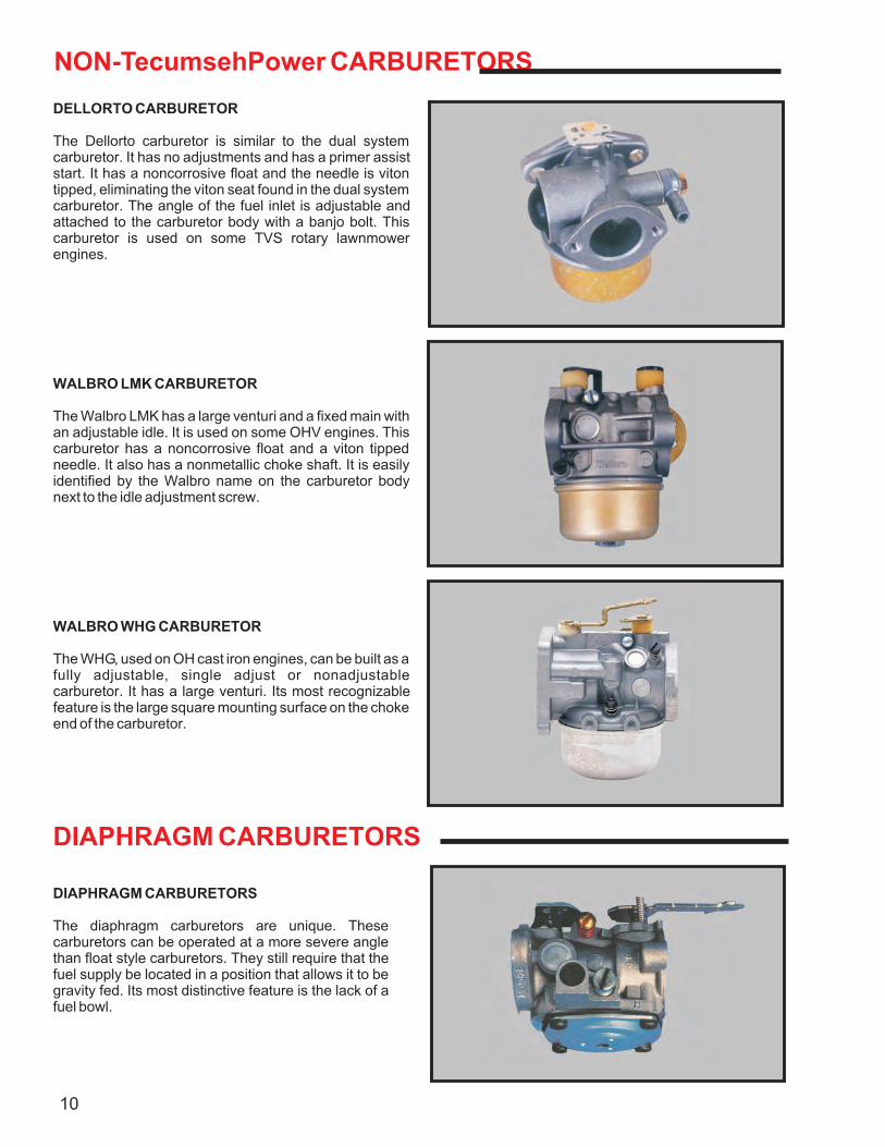
SERIES 8 CARBURETOR (EMISSION)
The Series 8 carburetor has both a fixed main and idle circuit. The fixed idle system is achieved by a restrictor jet that meters the fuel for the idle circuit. The idle restrictor jet will be capped to prevent access unless the cap is removed. The fixed main jet is part of the bowl nut. A ball plug is visible from the bottom, which seals the passage. This carburetor also has a serviceable main nozzle emulsion tube. It also has a stepped primer bulb.
8
CUTLINE
HOW TO IDENTIFY A TecumsehPower CARBURETOR(CONTINUED)
SERIES 9 CARBURETOR
The Series 9 carburetor is an emissions carburetor that uses the same carburetor body as the Series 8 but with a simple fixed idle system, identical to the one used on the Series 6 carburetor. It has the idle discharge port located at the 7 o'clock position on the throttle end of the carburetor. Identify this carburetor by the stepped primer bulb, the presence of a non-drilled idle mixing well and a serviceable main nozzle emulsion tube.
SERIES 10 (EMISSION)
The Series 10 carburetor is identical to the Series 8 carburetor with the addition of a choke. To assist in cold weather starts. It has a fixed idle and main. The idle restrictor jet will be capped to prevent access unless the cap is removed. The fixed main jet is part of the bowl nut. A ball plug is visible from the bottom, which seals the passage. This carburetor also has a serviceable main nozzle emulsion tube. It also has a stepped primer bulb to assist in starting.
SERIES 11
This carburetor adds a fuel chamber, built into the carburetor body, that feeds fuel into the venturi during the initial warm up period. This patented feature eliminates, hunting, surging and false starts inherent to emissions engines. However external identification of the Series “11” carburetor has been a challenge. To make this ID simple, the Series “11” carburetor idle restrictor cap will be black, and all others will be gray. The part number for the black cap is 640200 and the gray is 640053.
CARBURETOR CLEANING - SERIES 11 and SERIES 11 BRIDGED
With the additional fuel well welch plug removed, you can see the small plastic metering jet, which can be distorted if left to soak in a carb dip tank. Currently, this metering jet is not a serviceable part. Our position has been to soak a carburetor no more than ½ hour but the exception is the Series 11 carburetor. To be safe, service all TecumsehPower carburetors with Carburetor Spray # 696410 along with a .012” (.304 mm) gauge wire.
SERIES 11 BRIDGED
This carburetor is identical to the Series “11” with the exception of the center leg. A non-metallic jet is pressed into the center leg to allow additional fuel into the main jet for applications that require this fuel to enhance run performance
9
CAPPED JET
NONMETALLIC JET
STANDARD 11BRIDGEDSERIES 11
NON-TecumsehPower CARBURETORS
DELLORTO CARBURETOR
The Dellorto carburetor is similar to the dual system carburetor. It has no adjustments and has a primer assist start. It has a noncorrosive float and the needle is viton tipped, eliminating the viton seat found in the dual system carburetor. The angle of the fuel inlet is adjustable and attached to the carburetor body with a banjo bolt. This carburetor is used on some TVS rotary lawnmower engines.
WALBRO LMK CARBURETOR
The Walbro LMK has a large venturi and a fixed main with an adjustable idle. It is used on some OHV engines. This carburetor has a noncorrosive float and a viton tipped needle. It also has a nonmetallic choke shaft. It is easily identified by the Walbro name on the carburetor body next to the idle adjustment screw.
WALBRO WHG CARBURETOR
The WHG, used on OH cast iron engines, can be built as a fully adjustable, single adjust or nonadjustable carburetor. It has a large venturi. Its most recognizable feature is the large square mounting surface on the choke end of the carburetor.
DIAPHRAGM CARBURETORS
DIAPHRAGM CARBURETORS
The diaphragm carburetors are unique. These carburetors can be operated at a more severe angle than float style carburetors. They still require that the fuel supply be located in a position that allows it to be gravity fed. Its most distinctive feature is the lack of a fuel bowl.
10
DIAPHRAGM CARBURETORS(CONTINUED)
WTA WALBRO CARBURETOR
The WTA carburetor has a rubber-type diaphragm, which is exposed to intake pressure on one side and to atmospheric pressure on the other. The WTA is used on TC200 and 300 engines. There are two adjustment screws. They are the idle mixture screw and the idle RPM screw. The WTA has a choke and an all metal fuel inlet fitting. The Walbro name is molded onto the pump cover.
WT WALBRO CARBURETOR
The WT Walbro carburetor is used on the TC-II style engine. It is similar to the WTA carburetor but its reverse image. The WT has no choke lever and has a combination plastic and metal fuel inlet fitting.
TILLOTSON HU CARBURETOR
The Tillotson HU carburetor is the reverse image of the WTA Walbro carburetor. It is used on the TC-II. The Tillotson HU has a replaceable main and Tillotson is visible on the pump cover.
TecumsehPower TC CARBURETORThis carburetor has a fixed idle and main which meets the emissions standards for two cycle engines. The main jet is serviceable and can be accessed by removing the plastic cap. The jet is removed for cleaning purposes only, and must be covered after servicing to maintain compliance with emissions regulations.
11
CARBURETOR CLEANING SERIES 8 - 11
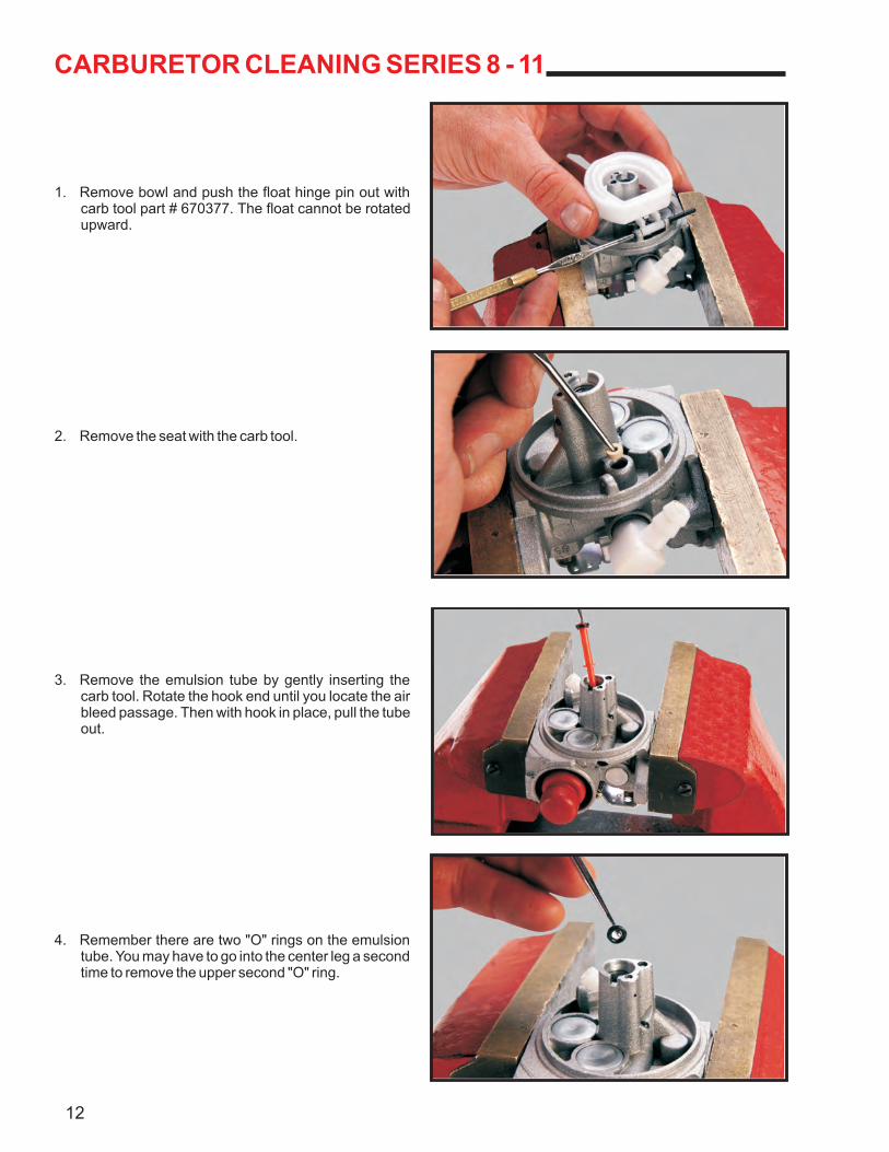
1. Remove bowl and push the float hinge pin out with carb tool part # 670377. The float cannot be rotated upward.
2. Remove the seat with the carb tool.
3. Remove the emulsion tube by gently inserting the carb tool. Rotate the hook end until you locate the air bleed passage. Then with hook in place, pull the tube out.
4. Remember there are two "O" rings on the emulsion tube. You may have to go into the center leg a second time to remove the upper second "O" ring.
12
CARBURETOR CLEANING SERIES 8 - 11(CONTINUED)
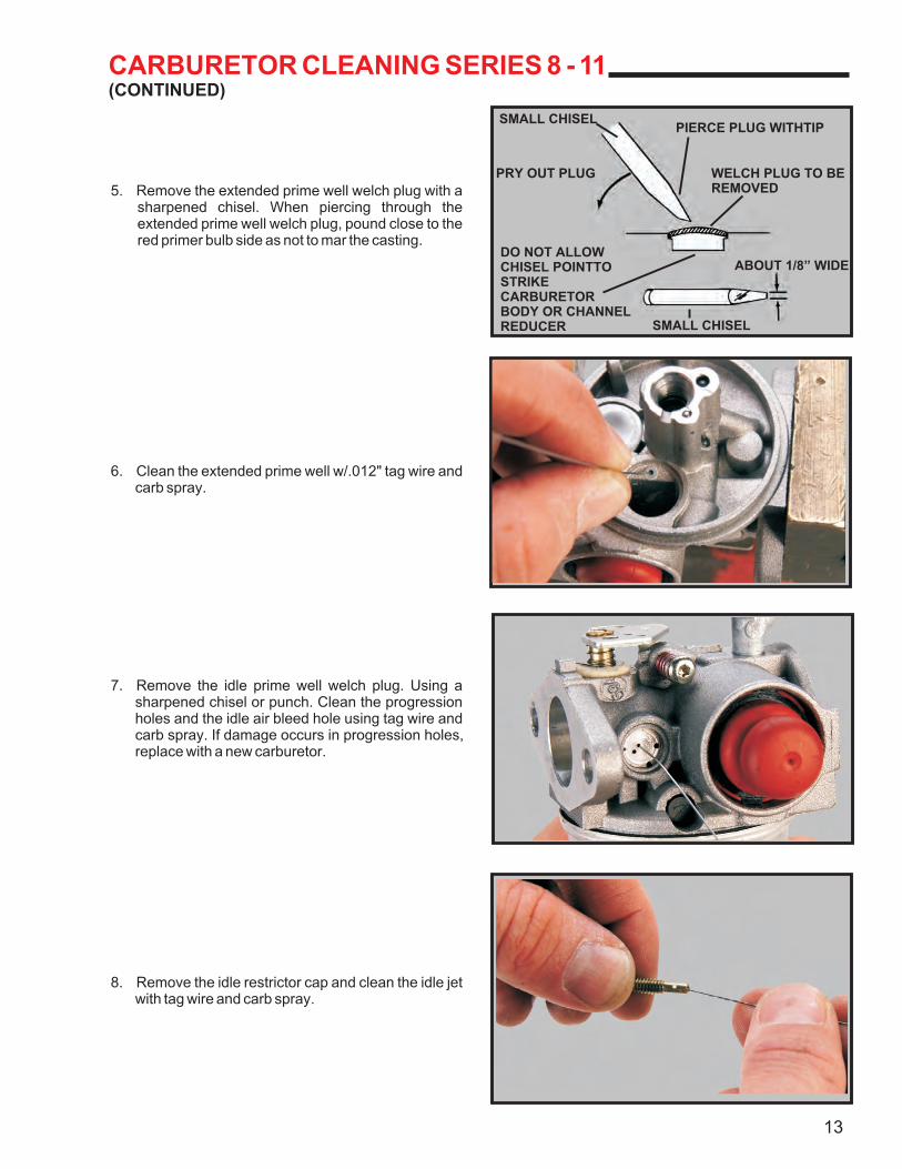
5. Remove the extended prime well welch plug with a sharpened chisel. When piercing through the extended prime well welch plug, pound close to the red primer bulb side as not to mar the casting.
6. Clean the extended prime well w/.012" tag wire and carb spray.
7. Remove the idle prime well welch plug. Using a sharpened chisel or punch. Clean the progression holes and the idle air bleed hole using tag wire and carb spray. If damage occurs in progression holes, replace with a new carburetor.
8. Remove the idle restrictor cap and clean the idle jet with tag wire and carb spray.
13
SMALL CHISEL
PRY OUT PLUG
DO NOT ALLOWCHISEL POINTTO STRIKECARBURETORBODY OR CHANNELREDUCER SMALL CHISEL
ABOUT 1/8” WIDE
WELCH PLUG TO BEREMOVED
PIERCE PLUG WITHTIP
CARBURETOR CLEANING SERIES 8 - 11(CONTINUED)
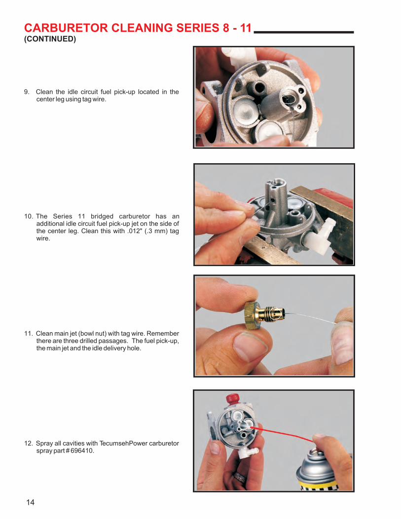
9. Clean the idle circuit fuel pick-up located in the center leg using tag wire.
10. The Series 11 bridged carburetor has an additional idle circuit fuel pick-up jet on the side of the center leg. Clean this with .012" (.3 mm) tag wire.
11. Clean main jet (bowl nut) with tag wire. Remember there are three drilled passages. The fuel pick-up, the main jet and the idle delivery hole.
12. Spray all cavities with TecumsehPower carburetor spray part # 696410.
14
CARBURETOR CLEANING SERIES 8 - 11(CONTINUED)
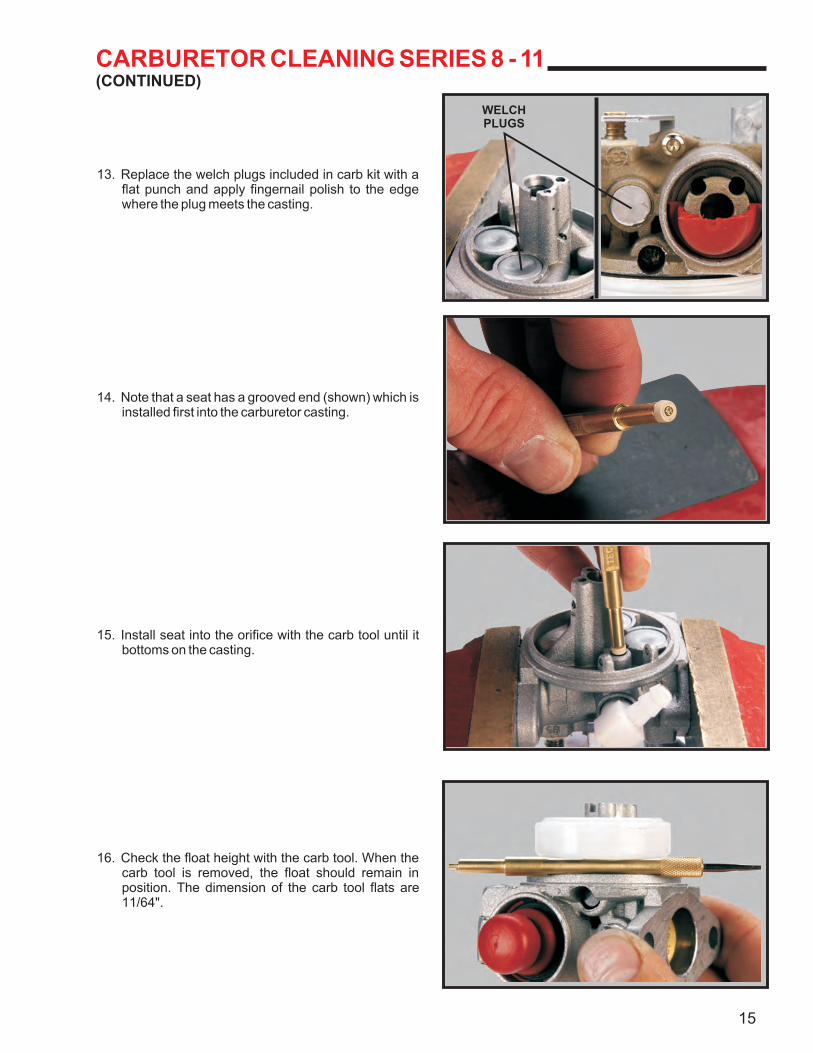
13. Replace the welch plugs included in carb kit with a flat punch and apply fingernail polish to the edge where the plug meets the casting.
14. Note that a seat has a grooved end (shown) which is installed first into the carburetor casting.
15. Install seat into the orifice with the carb tool until it bottoms on the casting.
16. Check the float height with the carb tool. When the carb tool is removed, the float should remain in position. The dimension of the carb tool flats are 11/64".
15
WELCHPLUGS
CARBURETOR CLEANING SERIES 8 - 11(CONTINUED)
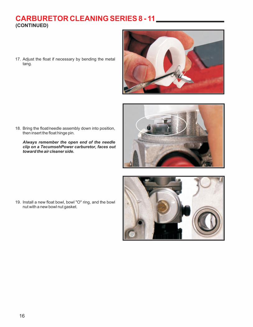
17. Adjust the float if necessary by bending the metal tang.
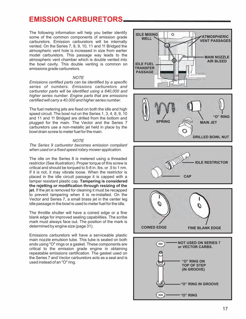
18. Bring the float/needle assembly down into position, then insert the float hinge pin.
Always remember the open end of the needle clip on a TecumsehPower carburetor, faces out toward the air cleaner side.
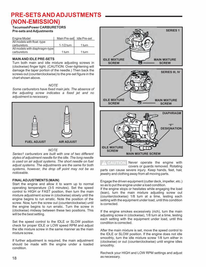
19. Install a new float bowl, bowl "O" ring, and the bowl nut with a new bowl nut gasket.
16
EMISSION CARBURETORS
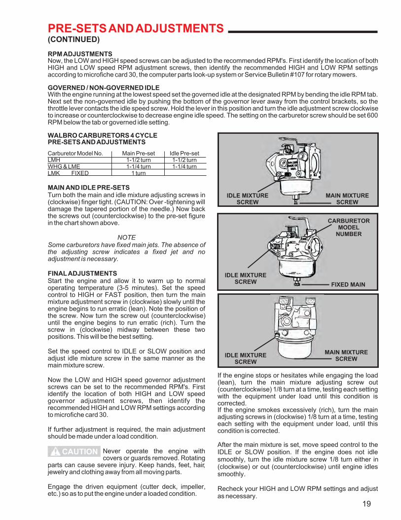
The following information will help you better identify some of the common components of emission grade carburetors. Emission carburetors will be internally vented. On the Series 7, 8, 9, 10, 11 and 11 Bridged the atmospheric vent hole is increased in size from earlier model carburetors. This passage way leads to the atmospheric vent chamber which is double vented into the bowl cavity. This double venting is common on emissions grade carburetors.
NOTEEmissions certified parts can be identified by a specific series of numbers. Emissions carburetors and carburetor parts will be identified using a 640,000 and higher series number. Engine parts that are emissions certified will carry a 40,000 and higher series number.
The fuel metering jets are fixed on both the idle and high speed circuit. The bowl nut on the Series 1, 3, 4, 8, 9, 10 and 11 and 11 Bridged are drilled from the bottom and plugged for the main. The Vector and the Series 7 carburetors use a non-metallic jet held in place by the bowl drain screw to meter fuel for the main.
NOTEThe Series 9 carburetor becomes emission compliant when used on a fixed speed rotary mower application.
The idle on the Series 8 is metered using a threaded restrictor (See illustration). Proper torque of this screw is critical and should be torqued to 5-8 in. lbs. or .5 to 1 nm. If it is not, it may vibrate loose. When the restrictor is placed in the idle circuit passage it is capped with a tamper resistant plastic cap. Tampering is considered the rejetting or modification through resizing of the jet. If the jet is removed for cleaning it must be recapped to prevent tampering when it is re-installed. On the Vector and Series 7, a small brass jet in the center leg idle passage in the bowl is used to meter fuel for the idle.
The throttle shutter will have a coined edge or a fine blank edge for improved sealing capabilities. The scribe mark must always face out. The position of the mark is determined by engine size (page 31).
Emissions carburetors will have a serviceable plastic main nozzle emulsion tube. This tube is sealed on both ends using "O" rings or a gasket. These components are critical to the emission grade engine in obtaining repeatable emissions certification. The gasket used on the Series 7 and Vector carburetors acts as a seal and is used instead of an "O" ring.
17
IDLE MIXINGWELL
IDLE FUELTRANSFERPASSAGE
ATMOSPHERICVENT PASSAGES
MAIN NOZZLEAIR BLEED
SPRING MAIN JET
DRILLED BOWL NUT
“O” RING
CAP
IDLE RESTRICTOR
COINED EDGE FINE BLANK EDGE
NOT USED ON SERIES 7or VECTOR CARBS.
“O” RING ONTOP OF STEP(IN GROOVE)
“O” RING IN GROOVE
“O” RING
PRE-SETS AND ADJUSTMENTS(NON-EMISSION)TecumsehPower CARBURETORSPre-sets and Adjustments
Engine Model Main Pre-set Idle Pre-setAll models with float -typecarburetors 1-1/2 turn 1 turnAll models with diaphragm-typecarburetors 1 turn 1 turn
MAIN AND IDLE PRE-SETSTurn both main and idle mixture adjusting screws in (clockwise) finger tight. (CAUTION: Over-tightening will damage the taper portion of the needle.) Then back the screws out (counterclockwise) to the pre-set figure in the chart shown above.
NOTESome carburetors have fixed main jets. The absence of the adjusting screw indicates a fixed jet and no adjustment is necessary.
NOTESeries1 carburetors are built with one of two different styles of adjustment needle for the idle. The long needle is used on air adjust systems. The short needle on fuel adjust systems. The adjustments are the same for both systems, however, the drop off point may not be as noticeable.
FINAL ADJUSTMENTS (MAIN)Start the engine and allow it to warm up to normal operating temperature (3-5 minutes). Set the speed control to HIGH or FAST position, then turn the main mixture adjustment screw in (clockwise) slowly until the engine begins to run erratic. Note the position of the screw. Now, turn the screw out (counterclockwise) until the engine begins to run erratic. Turn the screw in (clockwise) midway between these two positions. This will be the best setting.
Set the speed control to the IDLE or SLOW position check for proper IDLE or LOW speed RPM and adjust the idle mixture screw in the same manner as the main mixture screw.
If further adjustment is required, the main adjustment should be made with the engine under a loaded condition.
Never operate the engine with covers or guards removed. Rotating
parts can cause severe injury. Keep hands, feet, hair, jewelry and clothing away from all moving parts.
Engage the driven equipment (cutter deck, impeller, etc.) so as to put the engine under a load condition.If the engine stops or hesitates while engaging the load (lean), turn the main mixture adjusting screw out (counterclockwise) 1/8 turn at a time, testing each setting with the equipment under load, until this condition is corrected.
If the engine smokes excessively (rich), turn the main adjusting screw in (clockwise), 1/8 turn at a time, testing each setting with the equipment under load, until this condition is corrected.
After the main mixture is set, move the speed control to the IDLE or SLOW position. If the engine does not idle smoothly, turn the idle mixture screw 1/8 turn either in (clockwise) or out (counterclockwise) until engine idles smoothly.
Recheck your HIGH and LOW RPM settings and adjust as necessary.
CAUTION
18
FUEL ADJUST AIR ADJUST
SERIES 1
MAIN MIXTURESCREW
IDLE MIXTURESCREW
IDLE MIXTURESCREW
MAIN MIXTURESCREW
DIAPHRAGM
SERIES III, IV
“F”DESIGNATION
MAIN MIXTURE SCREW
IDLE MIXTURESCREW
PRE-SETS AND ADJUSTMENTS(CONTINUED)
RPM ADJUSTMENTSNow, the LOW and HIGH speed screws can be adjusted to the recommended RPM's. First identify the location of both HIGH and LOW speed RPM adjustment screws, then identify the recommended HIGH and LOW RPM settings according to microfiche card 30, the computer parts look-up system or Service Bulletin #107 for rotary mowers.
GOVERNED / NON-GOVERNED IDLEWith the engine running at the lowest speed set the governed idle at the designated RPM by bending the idle RPM tab. Next set the non-governed idle by pushing the bottom of the governor lever away from the control brackets, so the throttle lever contacts the idle speed screw. Hold the lever in this position and turn the idle adjustment screw clockwise to increase or counterclockwise to decrease engine idle speed. The setting on the carburetor screw should be set 600 RPM below the tab or governed idle setting.
WALBRO CARBURETORS 4 CYCLEPRE-SETS AND ADJUSTMENTS
Carburetor Model No. Main Pre-set Idle Pre-setLMH 1-1/2 turn 1-1/2 turnWHG & LME 1-1/4 turn 1-1/4 turnLMK FIXED 1 turn
MAIN AND IDLE PRE-SETSTurn both the main and idle mixture adjusting screws in (clockwise) finger tight. (CAUTION: Over -tightening will damage the tapered portion of the needle.) Now back the screws out (counterclockwise) to the pre-set figure in the chart shown above.
NOTESome carburetors have fixed main jets. The absence of the adjusting screw indicates a fixed jet and no adjustment is necessary.
FINAL ADJUSTMENTSStart the engine and allow it to warm up to normal operating temperature (3-5 minutes). Set the speed control to HIGH or FAST position, then turn the main mixture adjustment screw in (clockwise) slowly until the engine begins to run erratic (lean). Note the position of the screw. Now turn the screw out (counterclockwise) until the engine begins to run erratic (rich). Turn the screw in (clockwise) midway between these two positions. This will be the best setting.
Set the speed control to IDLE or SLOW position and adjust idle mixture screw in the same manner as the main mixture screw.
Now the LOW and HIGH speed governor adjustment screws can be set to the recommended RPM's. First identify the location of both HIGH and LOW speed governor adjustment screws, then identify the recommended HIGH and LOW RPM settings according to microfiche card 30.
If further adjustment is required, the main adjustment should be made under a load condition.
Engage the driven equipment (cutter deck, impeller, etc.) so as to put the engine under a loaded condition.
Never operate the engine with covers or guards removed. Rotating
parts can cause severe injury. Keep hands, feet, hair, jewelry and clothing away from all moving parts.
If the engine stops or hesitates while engaging the load (lean), turn the main mixture adjusting screw out (counterclockwise) 1/8 turn at a time, testing each setting with the equipment under load until this condition is corrected.If the engine smokes excessively (rich), turn the main adjusting screws in (clockwise) 1/8 turn at a time, testing each setting with the equipment under load, until this condition is corrected.
After the main mixture is set, move speed control to the IDLE or SLOW position. If the engine does not idle smoothly, turn the idle mixture screw 1/8 turn either in (clockwise) or out (counterclockwise) until engine idles smoothly.
Recheck your HIGH and LOW RPM settings and adjust as necessary.
19
MAIN MIXTURESCREW
IDLE MIXTURESCREW
FIXED MAIN
IDLE MIXTURESCREW
MAIN MIXTURESCREW
IDLE MIXTURESCREW
CARBURETORMODEL
NUMBER
CAUTION
20
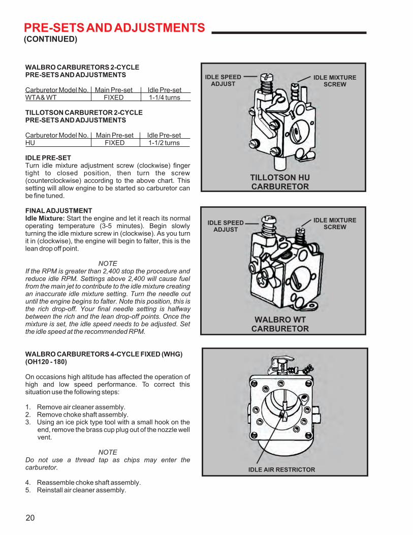
IDLE AIR RESTRICTOR
IDLE MIXTURESCREW
IDLE SPEEDADJUST
TILLOTSON HUCARBURETOR
IDLE MIXTURESCREW
IDLE SPEEDADJUST
WALBRO WTCARBURETOR
PRE-SETS AND ADJUSTMENTS(CONTINUED)
WALBRO CARBURETORS 2-CYCLEPRE-SETS AND ADJUSTMENTS
Carburetor Model No. Main Pre-set Idle Pre-setWTA & WT FIXED 1-1/4 turns
TILLOTSON CARBURETOR 2-CYCLEPRE-SETS AND ADJUSTMENTS
Carburetor Model No. Main Pre-set Idle Pre-setHU FIXED 1-1/2 turns
IDLE PRE-SETTurn idle mixture adjustment screw (clockwise) finger tight to closed position, then turn the screw (counterclockwise) according to the above chart. This setting will allow engine to be started so carburetor can be fine tuned.
FINAL ADJUSTMENTIdle Mixture: Start the engine and let it reach its normal operating temperature (3-5 minutes). Begin slowly turning the idle mixture screw in (clockwise). As you turn it in (clockwise), the engine will begin to falter, this is the lean drop off point.
NOTEIf the RPM is greater than 2,400 stop the procedure and reduce idle RPM. Settings above 2,400 will cause fuel from the main jet to contribute to the idle mixture creating an inaccurate idle mixture setting. Turn the needle out until the engine begins to falter. Note this position, this is the rich drop-off. Your final needle setting is halfway between the rich and the lean drop-off points. Once the mixture is set, the idle speed needs to be adjusted. Set the idle speed at the recommended RPM.
WALBRO CARBURETORS 4-CYCLE FIXED (WHG)(OH120 - 180)
On occasions high altitude has affected the operation of high and low speed performance. To correct this situation use the following steps:
1. Remove air cleaner assembly.2. Remove choke shaft assembly.3. Using an ice pick type tool with a small hook on the
end, remove the brass cup plug out of the nozzle well vent.
NOTEDo not use a thread tap as chips may enter the carburetor.
4. Reassemble choke shaft assembly.5. Reinstall air cleaner assembly.
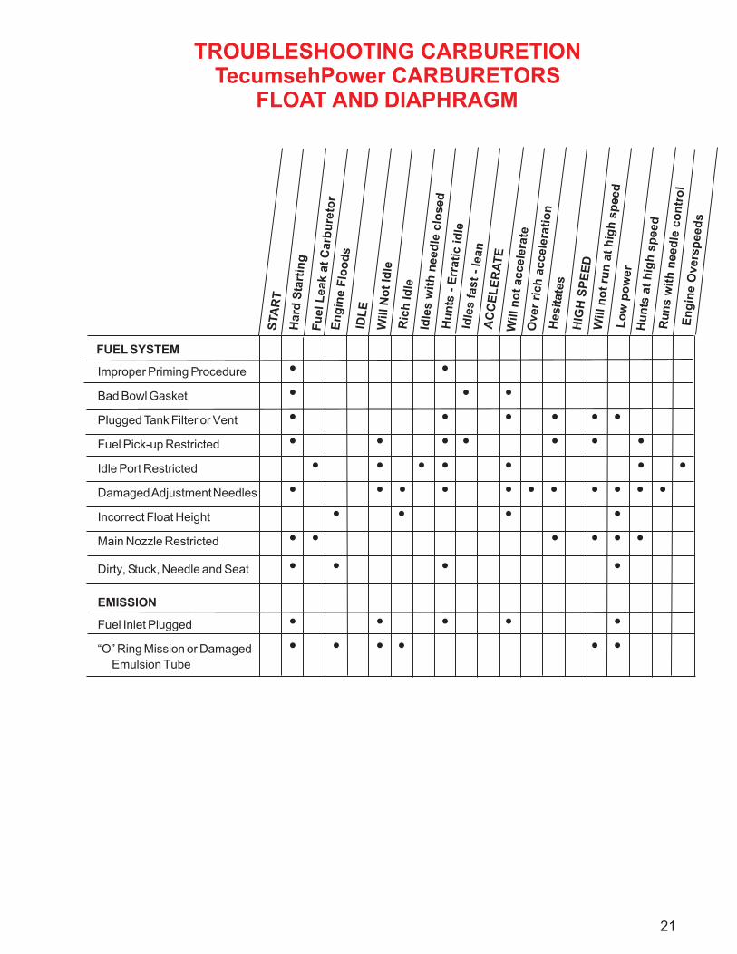
TROUBLESHOOTING CARBURETIONTecumsehPower CARBURETORS
FLOAT AND DIAPHRAGM
FUEL SYSTEM
Improper Priming Procedure • •Bad Bowl Gasket • • •Plugged Tank Filter or Vent • • • • • •Fuel Pick-up Restricted • • • • • • •Idle Port Restricted • • • • • • •Damaged Adjustment Needles • • • • • • • • • • •Incorrect Float Height • • • •Main Nozzle Restricted • • • • • •
Dirty, Stuck, Needle and Seat • • • •
EMISSION
Fuel Inlet Plugged • • • • •“O” Ring Mission or Damaged
Emulsion Tube
• • • • • •
Will n
ot
accele
rate
Hesit
ate
s
HIG
H S
PE
ED
Will n
ot
run
at
hig
h s
peed
Lo
w p
ow
er
Hu
nts
at
hig
h s
peed
Ru
ns w
ith
need
le c
on
tro
lE
ng
ine O
vers
peed
s
21
STA
RT
Hard
Sta
rtin
g
Fu
el L
eak a
t C
arb
ure
tor
En
gin
e F
loo
ds
IDL
E
Will N
ot
Idle
Ric
h Id
le
Idle
s w
ith
need
le c
losed
Hu
nts
- E
rrati
c id
leId
les f
ast
- le
an
AC
CE
LE
RA
TE
Over
rich
accele
rati
on
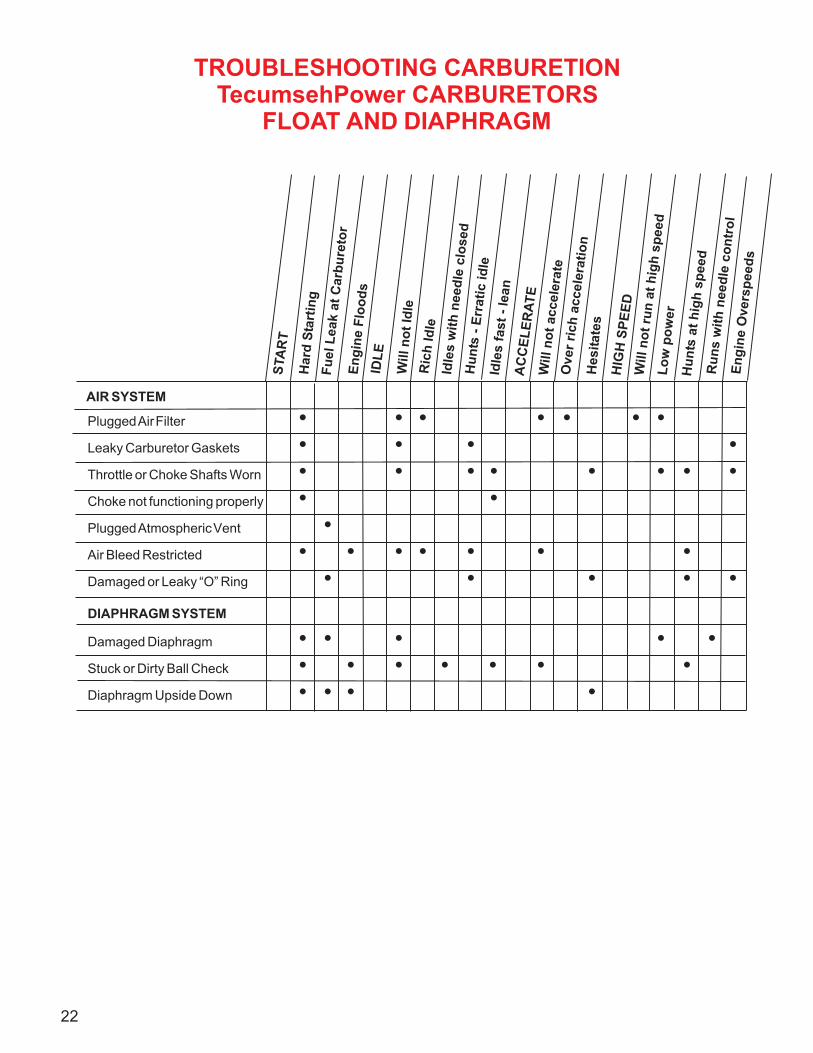
TROUBLESHOOTING CARBURETIONTecumsehPower CARBURETORS
FLOAT AND DIAPHRAGM
AIR SYSTEM
Plugged Air Filter • • • • • • •Leaky Carburetor Gaskets • • • •Throttle or Choke Shafts Worn • • • • • • • •Choke not functioning properly • •Plugged Atmospheric Vent •Air Bleed Restricted • • • • • • •Damaged or Leaky “O” Ring • • • • •
DIAPHRAGM SYSTEM
Damaged Diaphragm • • • • •Stuck or Dirty Ball Check • • • • • • •Diaphragm Upside Down • • • •
Will n
ot
accele
rate
Hesit
ate
s
HIG
H S
PE
ED
Will n
ot
run
at
hig
h s
peed
Lo
w p
ow
er
Hu
nts
at
hig
h s
peed
Ru
ns w
ith
need
le c
on
tro
lE
ng
ine O
vers
peed
s
22
STA
RT
Hard
Sta
rtin
gF
uel L
eak a
t C
arb
ure
tor
En
gin
e F
loo
ds
IDL
E
Will n
ot
Idle
Ric
h Id
leId
les w
ith
need
le c
losed
Hu
nts
- E
rrati
c id
leId
les f
ast
- le
an
AC
CE
LE
RA
TE
Over
rich
accele
rati
on
23
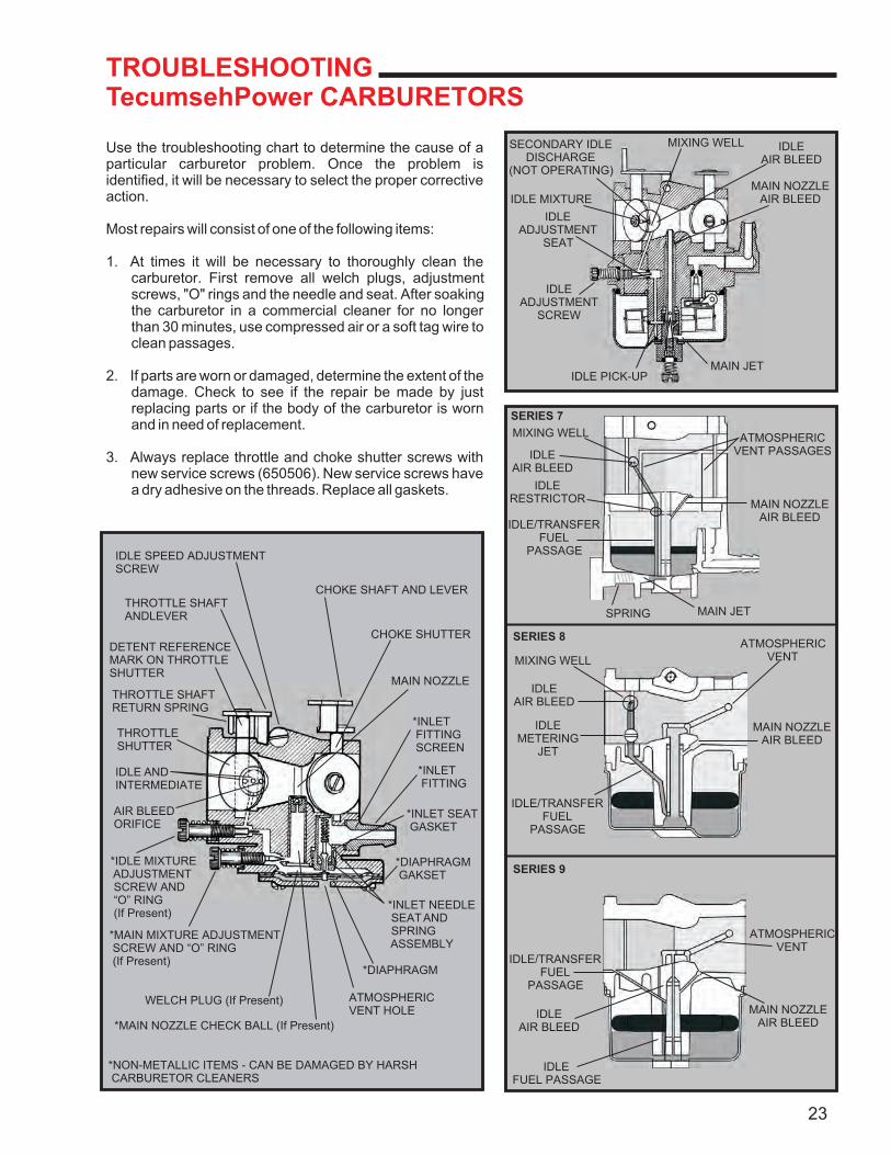
IDLE SPEED ADJUSTMENTSCREW
THROTTLE SHAFTANDLEVER
DETENT REFERENCEMARK ON THROTTLESHUTTER
THROTTLE SHAFTRETURN SPRING
THROTTLESHUTTER
IDLE ANDINTERMEDIATE
AIR BLEEDORIFICE
*IDLE MIXTURE ADJUSTMENT SCREW AND “O” RING (If Present)
*MAIN MIXTURE ADJUSTMENT SCREW AND “O” RING (If Present)
WELCH PLUG (If Present)
*MAIN NOZZLE CHECK BALL (If Present)
*NON-METALLIC ITEMS - CAN BE DAMAGED BY HARSH CARBURETOR CLEANERS
ATMOSPHERICVENT HOLE
*DIAPHRAGM
*INLET NEEDLE SEAT AND SPRING ASSEMBLY
*DIAPHRAGM GAKSET
*INLET SEAT GASKET
*INLET FITTING
*INLET FITTING SCREEN
MAIN NOZZLE
CHOKE SHUTTER
CHOKE SHAFT AND LEVER
SECONDARY IDLEDISCHARGE
(NOT OPERATING)
IDLE MIXTURE
IDLEADJUSTMENT
SEAT
IDLEADJUSTMENT
SCREW
MAIN JETIDLE PICK-UP
MAIN NOZZLEAIR BLEED
ATMOSPHERICVENT PASSAGES
MAIN NOZZLEAIR BLEED
MAIN JETSPRING
MIXING WELL IDLEAIR BLEED
MIXING WELL
IDLEAIR BLEED
IDLERESTRICTOR
IDLE/TRANSFERFUEL
PASSAGE
SERIES 7
MIXING WELL
IDLEAIR BLEED
IDLEMETERING
JET
IDLE/TRANSFERFUEL
PASSAGE
SERIES 8
IDLEAIR BLEED
IDLEFUEL PASSAGE
SERIES 9
MAIN NOZZLEAIR BLEED
MAIN NOZZLEAIR BLEED
ATMOSPHERICVENT
ATMOSPHERICVENT
IDLE/TRANSFERFUEL
PASSAGE
TROUBLESHOOTINGTecumsehPower CARBURETORS
Use the troubleshooting chart to determine the cause of a particular carburetor problem. Once the problem is identified, it will be necessary to select the proper corrective action.
Most repairs will consist of one of the following items:
1. At times it will be necessary to thoroughly clean the carburetor. First remove all welch plugs, adjustment screws, "O" rings and the needle and seat. After soaking the carburetor in a commercial cleaner for no longer than 30 minutes, use compressed air or a soft tag wire to clean passages.
2. If parts are worn or damaged, determine the extent of the damage. Check to see if the repair be made by just replacing parts or if the body of the carburetor is worn and in need of replacement.
3. Always replace throttle and choke shutter screws with new service screws (650506). New service screws have a dry adhesive on the threads. Replace all gaskets.
24
STA
RT
Hard
Sta
rtin
g
Fuel D
rippin
g F
rom
Carb
ure
tor
Flo
ods
Engin
e W
hen N
ot R
unnin
gID
LE
(Low
Speed)
Will
Not Id
leR
ich Idle
Idle
s W
ith N
eedle
Clo
sed
Err
atic
Idle
“L”
Needle
Needs
Fre
quent A
dju
stm
ent
Loads
Up W
hile
Idlin
gA
CC
EL
ER
AT
ION
& D
EC
EL
ER
AT
ION
Will
Not A
ccele
rate
Engin
e S
tops
When C
losi
ng T
hro
ttle
Ove
r-rich
Acc
ele
ratio
nH
IGH
SP
EE
D
Will
Not R
un A
t W
.O.T
.Low
Pow
er
Not R
ich D
rop O
ff
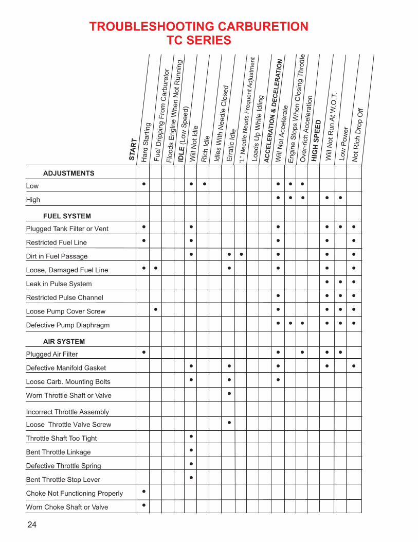
TROUBLESHOOTING CARBURETIONTC SERIES
ADJUSTMENTS
Low • • • • • •High • • • • •
FUEL SYSTEM
Plugged Tank Filter or Vent • • • • • •Restricted Fuel Line • • • • •Dirt in Fuel Passage • • • • • •Loose, Damaged Fuel Line • • • • • •Leak in Pulse System • • •Restricted Pulse Channel • • • •Loose Pump Cover Screw • • • • •Defective Pump Diaphragm • • • • • •
AIR SYSTEM
Plugged Air Filter • • • • •Defective Manifold Gasket • • • • •Loose Carb. Mounting Bolts • • •Worn Throttle Shaft or Valve •
Incorrect Throttle Assembly
Loose Throttle Valve Screw •Throttle Shaft Too Tight •Bent Throttle Linkage •Defective Throttle Spring •Bent Throttle Stop Lever •Choke Not Functioning Properly •Worn Choke Shaft or Valve •
STA
RT
Hard
Sta
rtin
g
Fuel D
rippin
g F
rom
Carb
ure
tor
Flo
ods
Engin
e W
hen N
ot R
unnin
gID
LE
(Low
Speed)
Will
Not Id
leR
ich Idle
Idle
s W
ith N
eedle
Clo
sed
Err
atic
Idle
“L”
Needle
Needs
Fre
quent A
dju
stm
ent
Loads
Up W
hile
Idlin
gA
CC
EL
ER
AT
ION
& D
EC
EL
ER
AT
ION
Will
Not A
ccele
rate
Engin
e S
tops
When C
losi
ng T
hro
ttle
Ove
r-rich
Acc
ele
ratio
nH
IGH
SP
EE
D
Will
Not R
un A
t W
.O.T
.Low
Pow
er
Not R
ich D
rop O
ff
TROUBLESHOOTING CARBURETIONTC SERIES
(CONTINUED)
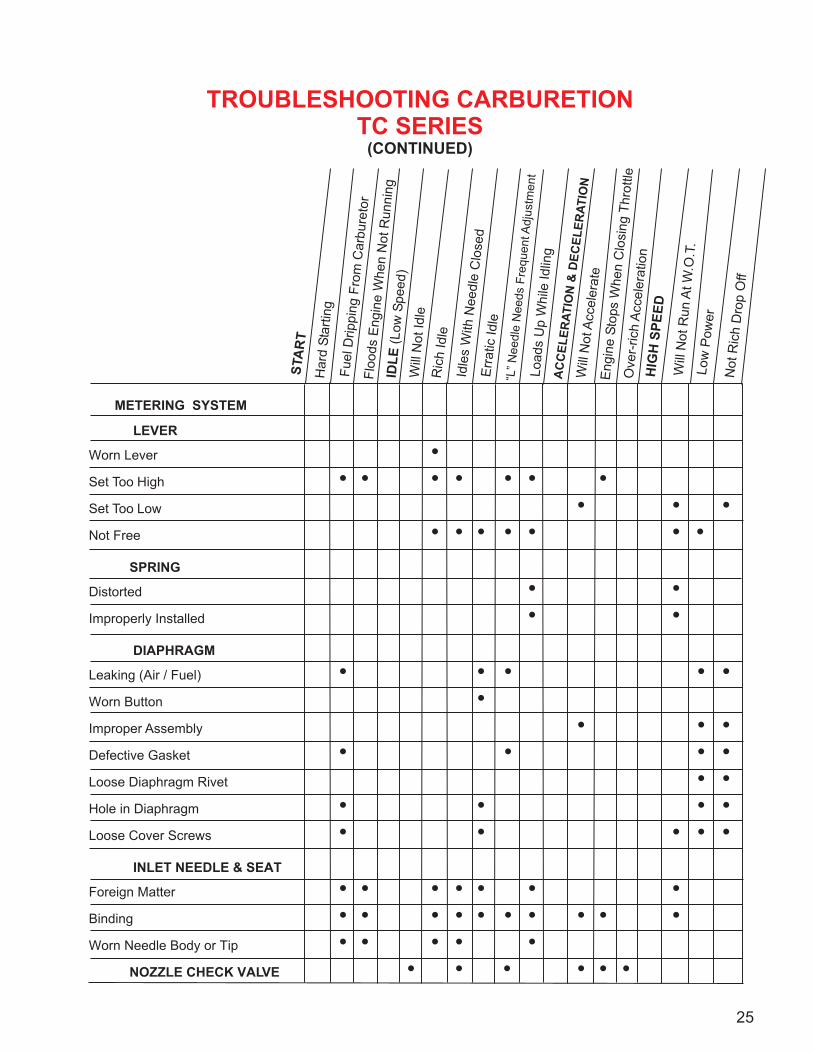
METERING SYSTEM
LEVER
Worn Lever •Set Too High • • • • • • •Set Too Low • • •Not Free • • • • • • •
SPRING
Distorted • •Improperly Installed • •
DIAPHRAGM
Leaking (Air / Fuel) • • • • •Worn Button •Improper Assembly • • •Defective Gasket • • • •Loose Diaphragm Rivet • •Hole in Diaphragm • • • •Loose Cover Screws • • • • •
INLET NEEDLE & SEAT
Foreign Matter • • • • • • •Binding • • • • • • • • • •Worn Needle Body or Tip • • • • • NOZZLE CHECK VALVE • • • • • •
25
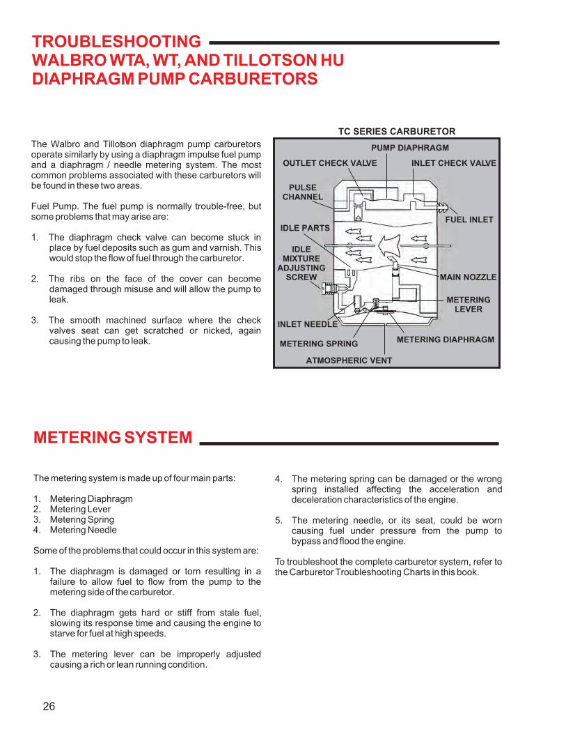
TROUBLESHOOTINGWALBRO WTA, WT, AND TILLOTSON HUDIAPHRAGM PUMP CARBURETORS
The Walbro and Tillotson diaphragm pump carburetors operate similarly by using a diaphragm impulse fuel pump and a diaphragm / needle metering system. The most common problems associated with these carburetors will be found in these two areas.
Fuel Pump. The fuel pump is normally trouble-free, but some problems that may arise are:
1. The diaphragm check valve can become stuck in place by fuel deposits such as gum and varnish. This would stop the flow of fuel through the carburetor.
2. The ribs on the face of the cover can become damaged through misuse and will allow the pump to leak.
3. The smooth machined surface where the check valves seat can get scratched or nicked, again causing the pump to leak.
METERING SYSTEM
The metering system is made up of four main parts:
1. Metering Diaphragm2. Metering Lever3. Metering Spring4. Metering Needle
Some of the problems that could occur in this system are:
1. The diaphragm is damaged or torn resulting in a failure to allow fuel to flow from the pump to the metering side of the carburetor.
2. The diaphragm gets hard or stiff from stale fuel, slowing its response time and causing the engine to starve for fuel at high speeds.
3. The metering lever can be improperly adjusted causing a rich or lean running condition.
4. The metering spring can be damaged or the wrong spring installed affecting the acceleration and deceleration characteristics of the engine.
5. The metering needle, or its seat, could be worn causing fuel under pressure from the pump to bypass and flood the engine.
To troubleshoot the complete carburetor system, refer to the Carburetor Troubleshooting Charts in this book.
26
PUMP DIAPHRAGM
INLET CHECK VALVE
FUEL INLET
MAIN NOZZLE
METERINGLEVER
METERING DIAPHRAGM
ATMOSPHERIC VENT
METERING SPRING
INLET NEEDLE
IDLEMIXTURE
ADJUSTINGSCREW
IDLE PARTS
PULSECHANNEL
OUTLET CHECK VALVE
TC SERIES CARBURETOR
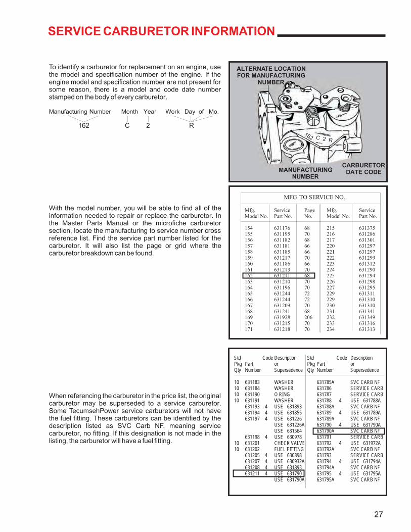
MFG. TO SERVICE NO.
Mfg. Service Page Mfg. ServiceModel No. Part No. No. Model No. Part No.
154 631176 68 215 631375155 631195 70 216 631286156 631182 68 217 631301157 631181 66 220 631297158 631185 66 221 631297159 631217 70 222 631299160 631186 66 223 631312161 631213 70 224 631290162 631211 68 225 631294163 631210 70 226 631298164 631196 70 227 631295165 631244 72 229 631311166 631244 72 229 631310167 631209 70 230 631310168 631241 68 231 631341169 631928 206 232 631349170 631215 70 233 631316171 631218 70 234 631313
Std Code Description Std Code DescriptionPkg Part or Pkg Part orQty Number Supersedence Qty Number Supersedence
10 631183 WASHER 631785A SVC CARB NF10 631184 WASHER 631786 SERVICE CARB10 631190 O RING 631787 SERVICE CARB10 631191 WASHER 631788 4 USE 631788A
631193 4 USE 631893 631788A SVC CARB NF631194 4 USE 631855 631789 4 USE 631789A631197 4 USE 631226 631789A SVC CARB NF
USE 631226A 631790 4 USE 631790AUSE 631564 631790A SVC CARB NF
631198 4 USE 630978 631791 SERVICE CARB10 631201 CHECK VALVE 631792 4 USE 631972A10 631202 FUEL FITTING 631792A SVC CARB NF
631205 4 USE 630898 631793 SERVICE CARB631207 4 USE 630932A 631794 4 USE 631794A631208 4 USE 631893 631794A SVC CARB NF631211 4 USE 631790 631795 4 USE 631795A
USE 631790A 631795A SVC CARB NF
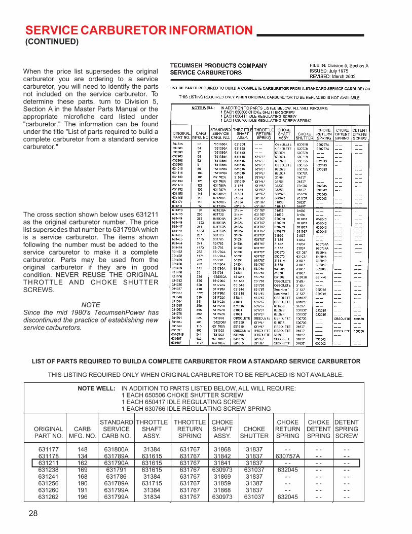
SERVICE CARBURETOR INFORMATION
To identify a carburetor for replacement on an engine, use the model and specification number of the engine. If the engine model and specification number are not present for some reason, there is a model and code date number stamped on the body of every carburetor.
Manufacturing Number Month Year Work Day of Mo.
162 C 2 R
With the model number, you will be able to find all of the information needed to repair or replace the carburetor. In the Master Parts Manual or the microfiche carburetor section, locate the manufacturing to service number cross reference list. Find the service part number listed for the carburetor. It will also list the page or grid where the carburetor breakdown can be found.
When referencing the carburetor in the price list, the original carburetor may be superseded to a service carburetor. Some TecumsehPower service carburetors will not have the fuel fitting. These carburetors can be identified by the description listed as SVC Carb NF, meaning service carburetor, no fitting. If this designation is not made in the listing, the carburetor will have a fuel fitting.
27
CARBURETORDATE CODEMANUFACTURING
NUMBER
162 C 2 R
ALTERNATE LOCATIONFOR MANUFACTURING
NUMBER
SERVICE CARBURETOR INFORMATION(CONTINUED)
When the price list supersedes the original carburetor you are ordering to a service carburetor, you will need to identify the parts not included on the service carburetor. To determine these parts, turn to Division 5, Section A in the Master Parts Manual or the appropriate microfiche card listed under "carburetor." The information can be found under the title "List of parts required to build a complete carburetor from a standard service carburetor."
The cross section shown below uses 631211 as the original carburetor number. The price list supersedes that number to 631790A which is a service carburetor. The items shown following the number must be added to the service carburetor to make it a complete carburetor. Parts may be used from the original carburetor if they are in good condition. NEVER REUSE THE ORIGINAL THROTTLE AND CHOKE SHUTTER SCREWS.
NOTESince the mid 1980's TecumsehPower has discontinued the practice of establishing new service carburetors.
28
LIST OF PARTS REQUIRED TO BUILD A COMPLETE CARBURETOR FROM A STANDARD SERVICE CARBURETOR
THIS LISTING REQUIRED ONLY WHEN ORIGINAL CARBURETOR TO BE REPLACED IS NOT AVAILABLE.
NOTE WELL: IN ADDITION TO PARTS LISTED BELOW, ALL WILL REQUIRE:1 EACH 650506 CHOKE SHUTTER SCREW1 EACH 650417 IDLE REGULATING SCREW1 EACH 630766 IDLE REGULATING SCREW SPRING
STANDARD THROTTLE THROTTLE CHOKE CHOKE CHOKE DETENTORIGINAL CARB SERVICE SHAFT RETURN SHAFT CHOKE RETURN DETENT SPRINGPART NO. MFG. NO. CARB NO. ASSY. SPRING ASSY. SHUTTER SPRING SPRING SCREW
631177 148 631800A 31384 631767 31868 31837 - - - - - -631178 134 631789A 631615 631767 31842 31837 630757A - - - -631211 162 631790A 631615 631767 31841 31837 - - - - - -631238 169 631791 631615 631767 630973 631037 632045 - - - -631241 168 631786 31384 631767 31869 31837 - - - - - -631256 190 631789A 631715 631767 31859 31387 - - - - - -631260 191 631799A 31384 631767 31868 31837 - - - - - -631262 196 631799A 31834 631767 630973 631037 632045 - - - -
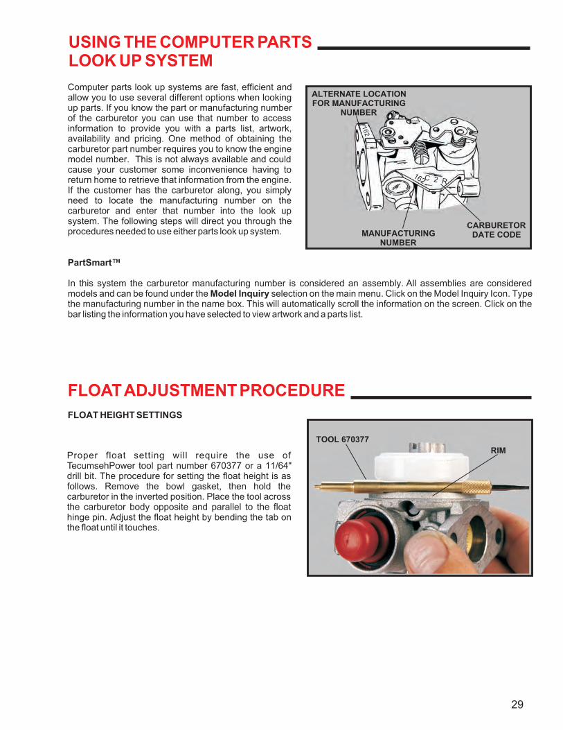
USING THE COMPUTER PARTSLOOK UP SYSTEM
Computer parts look up systems are fast, efficient and allow you to use several different options when looking up parts. If you know the part or manufacturing number of the carburetor you can use that number to access information to provide you with a parts list, artwork, availability and pricing. One method of obtaining the carburetor part number requires you to know the engine model number. This is not always available and could cause your customer some inconvenience having to return home to retrieve that information from the engine. If the customer has the carburetor along, you simply need to locate the manufacturing number on the carburetor and enter that number into the look up system. The following steps will direct you through the procedures needed to use either parts look up system.
PartSmart™
In this system the carburetor manufacturing number is considered an assembly. All assemblies are considered models and can be found under the Model Inquiry selection on the main menu. Click on the Model Inquiry Icon. Type the manufacturing number in the name box. This will automatically scroll the information on the screen. Click on the bar listing the information you have selected to view artwork and a parts list.
FLOAT HEIGHT SETTINGS
FLOAT ADJUSTMENT PROCEDURE
Proper float setting will require the use of TecumsehPower tool part number 670377 or a 11/64" drill bit. The procedure for setting the float height is as follows. Remove the bowl gasket, then hold the carburetor in the inverted position. Place the tool across the carburetor body opposite and parallel to the float hinge pin. Adjust the float height by bending the tab on the float until it touches.
29
RIM
TOOL 670377
CARBURETORDATE CODE
162C 2 R
MANUFACTURINGNUMBER
ALTERNATE LOCATIONFOR MANUFACTURING
NUMBER
162
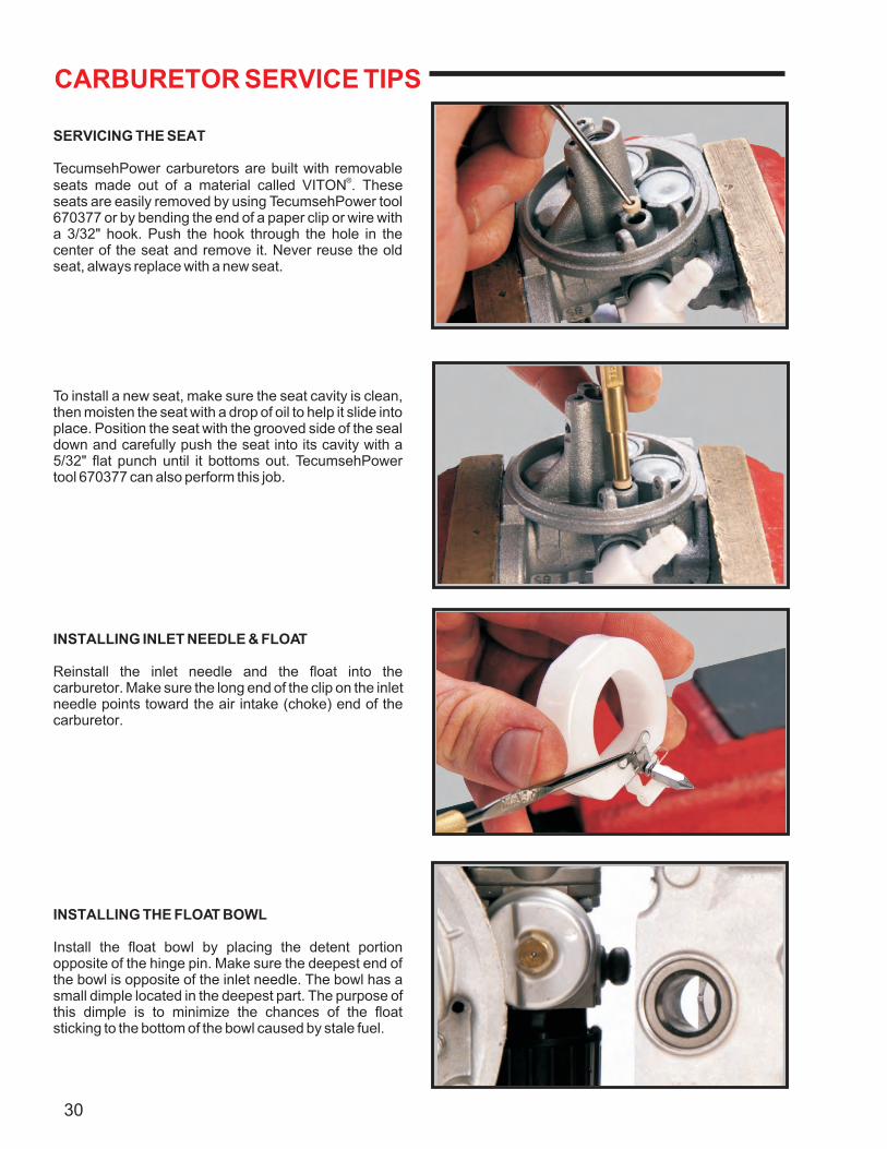
CARBURETOR SERVICE TIPS
SERVICING THE SEAT
TecumsehPower carburetors are built with removable ®seats made out of a material called VITON . These
seats are easily removed by using TecumsehPower tool 670377 or by bending the end of a paper clip or wire with a 3/32" hook. Push the hook through the hole in the center of the seat and remove it. Never reuse the old seat, always replace with a new seat.
To install a new seat, make sure the seat cavity is clean, then moisten the seat with a drop of oil to help it slide into place. Position the seat with the grooved side of the seal down and carefully push the seat into its cavity with a 5/32" flat punch until it bottoms out. TecumsehPower tool 670377 can also perform this job.
INSTALLING INLET NEEDLE & FLOAT
Reinstall the inlet needle and the float into the carburetor. Make sure the long end of the clip on the inlet needle points toward the air intake (choke) end of the carburetor.
INSTALLING THE FLOAT BOWL
Install the float bowl by placing the detent portion opposite of the hinge pin. Make sure the deepest end of the bowl is opposite of the inlet needle. The bowl has a small dimple located in the deepest part. The purpose of this dimple is to minimize the chances of the float sticking to the bottom of the bowl caused by stale fuel.
30
CARBURETOR SERVICE TIPS(CONTINUED)
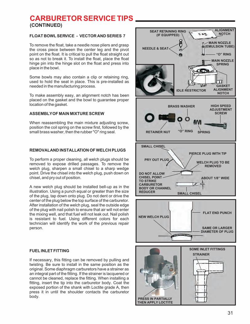
FLOAT BOWL SERVICE - VECTOR AND SERIES 7
To remove the float, take a needle nose pliers and grasp the cross piece between the center leg and the pivot point on the float. It is critical to pull the float straight out so as not to break it. To install the float, place the float hinge pin into the hinge slot on the float and press into place in the bowl.
Some bowls may also contain a clip or retaining ring, used to hold the seat in place. This is pre-installed as needed in the manufacturing process.
To make assembly easy, an alignment notch has been placed on the gasket and the bowl to guarantee proper location of the gasket.
ASSEMBLY OF MAIN MIXTURE SCREW
When reassembling the main mixture adjusting screw, position the coil spring on the screw first, followed by the small brass washer, then the rubber "O" ring seal.
REMOVAL AND INSTALLATION OF WELCH PLUGS
To perform a proper cleaning, all welch plugs should be removed to expose drilled passages. To remove the welch plug, sharpen a small chisel to a sharp wedge point. Drive the chisel into the welch plug, push down on chisel, and pry out of position.
A new welch plug should be installed bell-up as in the illustration. Using a punch equal or greater than the size of the plug, tap down onto plug. Do not dent or drive the center of the plug below the top surface of the carburetor. After installation of the welch plug, seal the outside edge of the plug with nail polish to ensure that air will not enter the mixing well, and that fuel will not leak out. Nail polish is resistant to fuel. Using different colors for each technician will identify the work of the previous repair person.
FUEL INLET FITTING
If necessary, this fitting can be removed by pulling and twisting. Be sure to install in the same position as the original. Some diaphragm carburetors have a strainer as an integral part of the fitting. If the strainer is lacquered or cannot be cleaned, replace the fitting. When installing a fitting, insert the tip into the carburetor body. Coat the exposed portion of the shank with Loctite grade A, then press it in until the shoulder contacts the carburetor body.
31
SOME INLET FITTINGS
STRAINER
FLAT END PUNCHNEW WELCH PLUG
SAME OR LARGERDIAMETER OF PLUG
SMALL CHISEL
PIERCE PLUG WITH TIP
WELCH PLUG TO BEREMOVED
ABOUT 1/8” WIDE
SMALL CHISEL
PRY OUT PLUG
DO NOT ALLOWCHISEL POINTTO STRIKECARBURETORBODY OR CHANNELREDUCER
HIGH SPEEDADJUSTMENT
SCREW
BRASS WASHER
RETAINER NUT “O” RING SPRING
ALIGNMENTNOTCH
MAIN NOZZLE(EMULSION TUBE)
“O” RING
MAIN NOZZLESPRING
IDLE RESTRICTOR
NEEDLE & SEAT
SEAT RETAINING RING(IF EQUIPPED)
GASKETALIGNMENT
NOTCH
PRESS IN PARTIALLYTHEN APPLY LOCTITE
CARBURETOR SERVICE TIPS(CONTINUED)
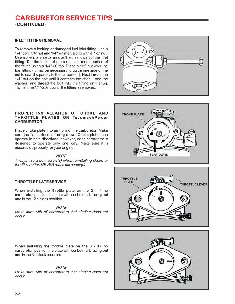
INLET FITTING REMOVAL
To remove a leaking or damaged fuel inlet fitting, use a 1/4" bolt, 1/4" nut and 1/4" washer, along with a 1/2” nut. Use a pliers or vise to remove the plastic part of the inlet fitting. Tap the inside of the remaining metal portion of the fitting using a 1/4"-20 tap. Place a 1/2” nut over the fuel fitting (it may be necessary to guide one side of the nut to seat it squarely to the carburetor). Next thread the 1/4" nut on the bolt until it contacts the shank, add the washer, and thread the bolt into the fitting until snug. Tighten the 1/4"-20 nut until the fitting is removed.
PROPER INSTALLATION OF CHOKE AND THROTTLE PLATES ON TecumsehPower CARBURETOR
Place choke plate into air horn of the carburetor. Make sure the flat surface is facing down. Choke plates can operate in both directions, however, each carburetor is designed to operate only one way. Make sure it is assembled properly for your engine.
NOTEAlways use a new screw(s) when reinstalling choke or throttle shutter. NEVER reuse old screw(s).
THROTTLE PLATE SERVICE
When installing the throttle plate on the 2 - 7 hp carburetor, position the plate with scribe mark facing out and in the 12 o'clock position.
NOTEMake sure with all carburetors that binding does not occur.
When installing the throttle plate on the 8 - 17 hp carburetor, position the plate with scribe mark facing out and in the 3 o'clock position.
NOTEMake sure with all carburetors that binding does not occur.
32
CHOKE PLATE
FLAT DOWN
THROTTLEPLATE
THROTTLE LEVER
CARBURETOR SERVICE TIPS(CONTINUED)
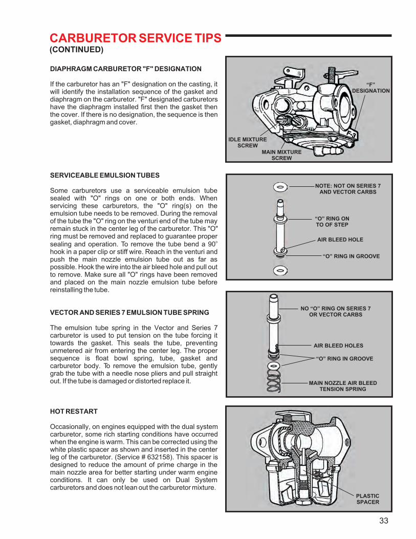
DIAPHRAGM CARBURETOR "F" DESIGNATION
If the carburetor has an "F" designation on the casting, it will identify the installation sequence of the gasket and diaphragm on the carburetor. "F" designated carburetors have the diaphragm installed first then the gasket then the cover. If there is no designation, the sequence is then gasket, diaphragm and cover.
SERVICEABLE EMULSION TUBES
Some carburetors use a serviceable emulsion tube sealed with "O" rings on one or both ends. When servicing these carburetors, the "O" ring(s) on the emulsion tube needs to be removed. During the removal of the tube the "O" ring on the venturi end of the tube may remain stuck in the center leg of the carburetor. This "O" ring must be removed and replaced to guarantee proper
osealing and operation. To remove the tube bend a 90 hook in a paper clip or stiff wire. Reach in the venturi and push the main nozzle emulsion tube out as far as possible. Hook the wire into the air bleed hole and pull out to remove. Make sure all "O" rings have been removed and placed on the main nozzle emulsion tube before reinstalling the tube.
VECTOR AND SERIES 7 EMULSION TUBE SPRING
The emulsion tube spring in the Vector and Series 7 carburetor is used to put tension on the tube forcing it towards the gasket. This seals the tube, preventing unmetered air from entering the center leg. The proper sequence is float bowl spring, tube, gasket and carburetor body. To remove the emulsion tube, gently grab the tube with a needle nose pliers and pull straight out. If the tube is damaged or distorted replace it.
HOT RESTART
Occasionally, on engines equipped with the dual system carburetor, some rich starting conditions have occurred when the engine is warm. This can be corrected using the white plastic spacer as shown and inserted in the center leg of the carburetor. (Service # 632158). This spacer is designed to reduce the amount of prime charge in the main nozzle area for better starting under warm engine conditions. It can only be used on Dual System carburetors and does not lean out the carburetor mixture.
33
“F”DESIGNATION
IDLE MIXTURESCREW
MAIN MIXTURESCREW
NOTE: NOT ON SERIES 7AND VECTOR CARBS
“O” RING ONTO OF STEP
AIR BLEED HOLE
“O” RING IN GROOVE
NO “O” RING ON SERIES 7OR VECTOR CARBS
AIR BLEED HOLES
“O” RING IN GROOVE
MAIN NOZZLE AIR BLEEDTENSION SPRING
PLASTICSPACER
CAUTION
PRIMER BULB SERVICE
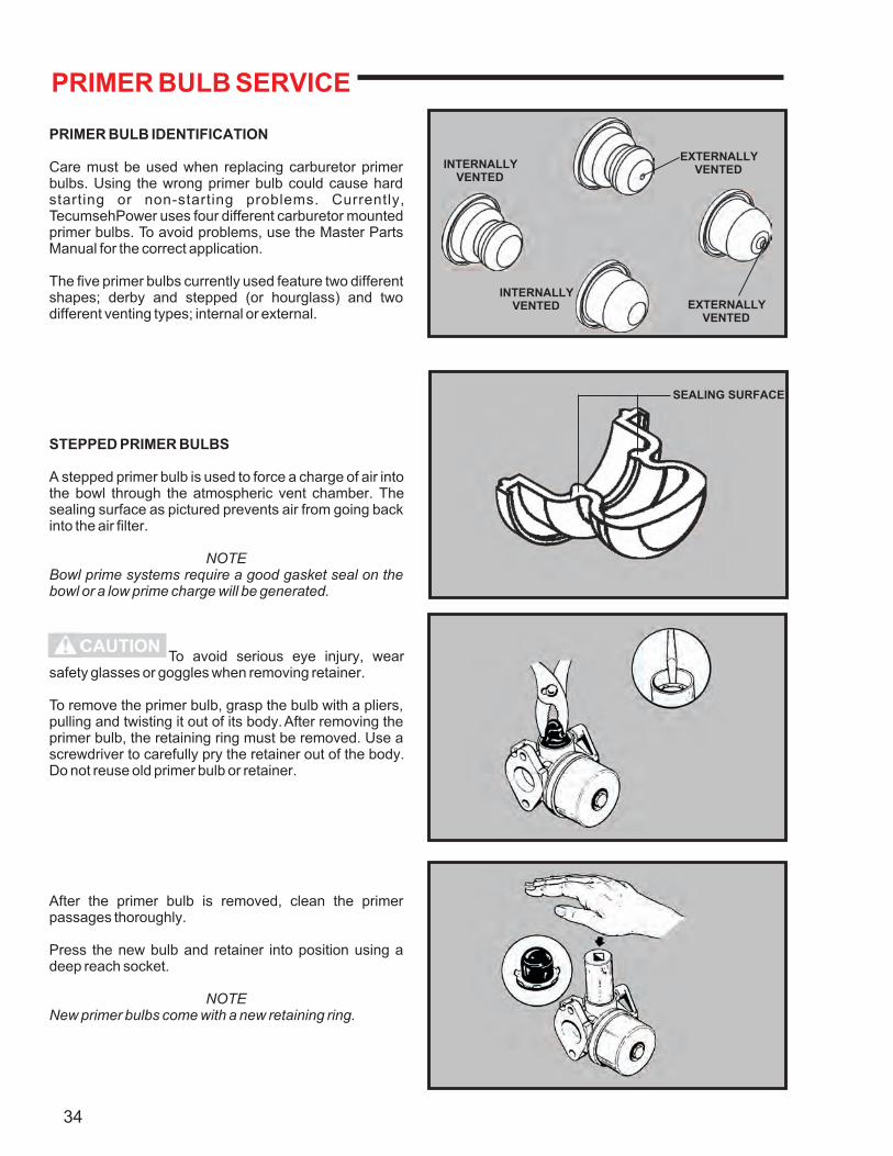
PRIMER BULB IDENTIFICATION
Care must be used when replacing carburetor primer bulbs. Using the wrong primer bulb could cause hard starting or non-starting problems. Currently, TecumsehPower uses four different carburetor mounted primer bulbs. To avoid problems, use the Master Parts Manual for the correct application.
The five primer bulbs currently used feature two different shapes; derby and stepped (or hourglass) and two different venting types; internal or external.
STEPPED PRIMER BULBS
A stepped primer bulb is used to force a charge of air into the bowl through the atmospheric vent chamber. The sealing surface as pictured prevents air from going back into the air filter.
NOTEBowl prime systems require a good gasket seal on the bowl or a low prime charge will be generated.
To avoid serious eye injury, wear safety glasses or goggles when removing retainer.
To remove the primer bulb, grasp the bulb with a pliers, pulling and twisting it out of its body. After removing the primer bulb, the retaining ring must be removed. Use a screwdriver to carefully pry the retainer out of the body. Do not reuse old primer bulb or retainer.
After the primer bulb is removed, clean the primer passages thoroughly.
Press the new bulb and retainer into position using a deep reach socket.
NOTENew primer bulbs come with a new retaining ring.
34
SEALING SURFACE
INTERNALLYVENTED
INTERNALLYVENTED
EXTERNALLYVENTED
EXTERNALLYVENTED
FUEL FILTERS
TecumsehPower engines use some form of filtration prior to the carburetor. When a non-TecumsehPower tank is used, an in- line fuel filter between the tank and carburetor is required. The filters use a 75 micron fibrous paper to trap even the smallest particles of dirt while maintaining the same flow rate. An arrow showing the direction of flow is molded into the body of the filter to aid in installation.
FUEL TANK FILTERS
All fuel tanks provided by TecumsehPower have a 75 micron stainless steel filter screen molded right into the tank over the fuel outlet. On TC series engines, a fuel filter is located on the fuel line in the tank. These filters can become restricted when foreign debris enters the tank or when varnish and gum deposits form due to stale fuel. Be sure to check these areas if you have a fuel flow problem.
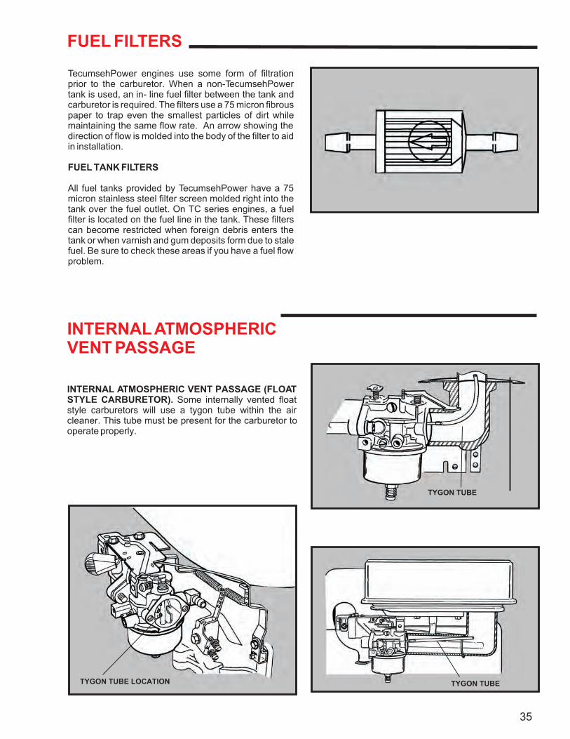
INTERNAL ATMOSPHERICVENT PASSAGE
INTERNAL ATMOSPHERIC VENT PASSAGE (FLOAT STYLE CARBURETOR). Some internally vented float style carburetors will use a tygon tube within the air cleaner. This tube must be present for the carburetor to operate properly.
35
TYGON TUBE
TYGON TUBETYGON TUBE LOCATION
FAILURE ANALYSIS
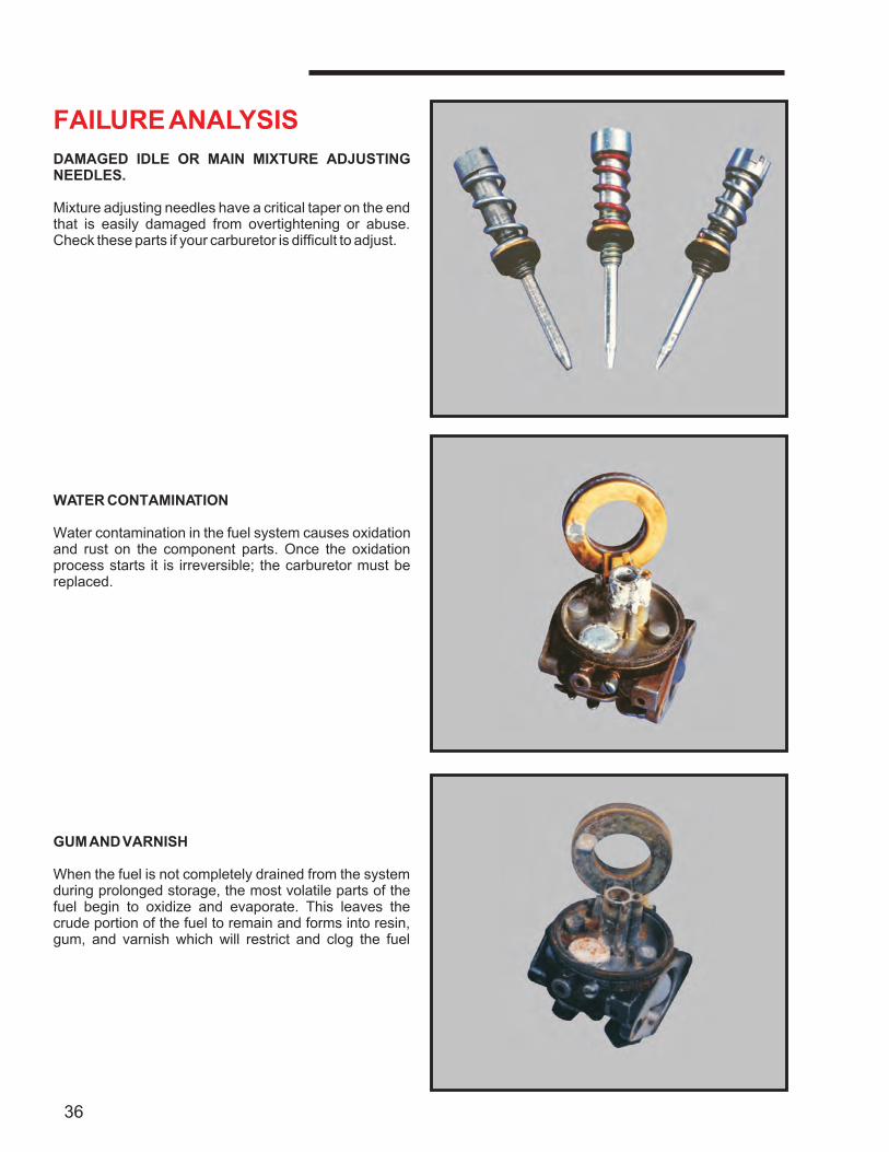
DAMAGED IDLE OR MAIN MIXTURE ADJUSTING NEEDLES.
Mixture adjusting needles have a critical taper on the end that is easily damaged from overtightening or abuse. Check these parts if your carburetor is difficult to adjust.
WATER CONTAMINATION
Water contamination in the fuel system causes oxidation and rust on the component parts. Once the oxidation process starts it is irreversible; the carburetor must be replaced.
GUM AND VARNISH
When the fuel is not completely drained from the system during prolonged storage, the most volatile parts of the fuel begin to oxidize and evaporate. This leaves the crude portion of the fuel to remain and forms into resin, gum, and varnish which will restrict and clog the fuel
36
system's passages.
FAILURE ANALYSIS(CONTINUED)
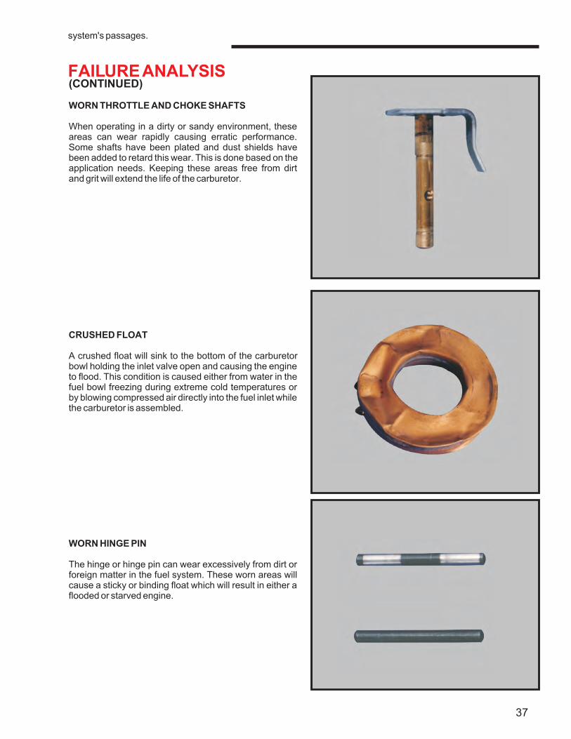
WORN THROTTLE AND CHOKE SHAFTS
When operating in a dirty or sandy environment, these areas can wear rapidly causing erratic performance. Some shafts have been plated and dust shields have been added to retard this wear. This is done based on the application needs. Keeping these areas free from dirt and grit will extend the life of the carburetor.
CRUSHED FLOAT
A crushed float will sink to the bottom of the carburetor bowl holding the inlet valve open and causing the engine to flood. This condition is caused either from water in the fuel bowl freezing during extreme cold temperatures or by blowing compressed air directly into the fuel inlet while the carburetor is assembled.
WORN HINGE PIN
The hinge or hinge pin can wear excessively from dirt or foreign matter in the fuel system. These worn areas will cause a sticky or binding float which will result in either a flooded or starved engine.
37
FAILURE ANALYSIS
(CONTINUED)
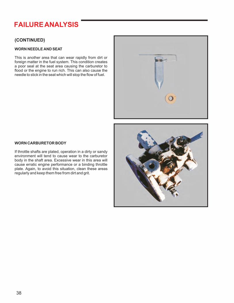
WORN NEEDLE AND SEAT
This is another area that can wear rapidly from dirt or foreign matter in the fuel system. This condition creates a poor seal at the seat area causing the carburetor to flood or the engine to run rich. This can also cause the needle to stick in the seat which will stop the flow of fuel.
WORN CARBURETOR BODY
If throttle shafts are plated, operation in a dirty or sandy environment will tend to cause wear to the carburetor body in the shaft area. Excessive wear in this area will cause erratic engine performance or a binding throttle plate. Again, to avoid this situation, clean these areas regularly and keep them free from dirt and grit.
38

Litho in U.S.A.Form No. 695907 R12/07
TecumsehPower Company900 North Street
Grafton, WI 53024Phone: 262-377-2700FAX: 262-377-4485
TecumsehPower International, LTD152-154 Commercial Road
Staines, MiddlesexUnited Kingdom TW18 2QPPhone: (44) 1 784-450785
Fax: 1 784-453563
www.TecumsehPower.com
ENGINES TRANSMISSIONS&
TecumsehPower
Provided by Barrett Small EngineTecumseh Carburetor Parts
Tecumseh Carburetors