Embed Size (px)
Citation preview
TECP-31-106 Issue 2 May 2016
Fiber Entrance Cabinet (FEC-10K) Installation Instructions
FEC-10K Content Page
INTRODUCTION . . . . . . . . . . . . . . . . . . . . . . . . . . . . . . . . . . . . . . . . . . . . . . . . . . . . . . . . . . . . . . . . . . . . . . . . . . . . . 2
RELATED PUBLICATIONS . . . . . . . . . . . . . . . . . . . . . . . . . . . . . . . . . . . . . . . . . . . . . . . . . . . . . . . . . . . . . . . . . . . . . . . 2
1 DESCRIPTION. . . . . . . . . . . . . . . . . . . . . . . . . . . . . . . . . . . . . . . . . . . . . . . . . . . . . . . . . . . . . . . . . . . . . . . . . . 3
2 DIMENSIONS AND SPECIFICATIONS . . . . . . . . . . . . . . . . . . . . . . . . . . . . . . . . . . . . . . . . . . . . . . . . . . . . . . . . . . 4
2.1 Ship-Along Parts . . . . . . . . . . . . . . . . . . . . . . . . . . . . . . . . . . . . . . . . . . . . . . . . . . . . . . . . . . . . . . . . . . 6
2.2 Tools and Materials Required for Installation . . . . . . . . . . . . . . . . . . . . . . . . . . . . . . . . . . . . . . . . . . . . . . 6
3 INSTALLATION PROCEDURE. . . . . . . . . . . . . . . . . . . . . . . . . . . . . . . . . . . . . . . . . . . . . . . . . . . . . . . . . . . . . . . . 7
3.1 Select Cable Configuration; Move Mounting Plates if Required . . . . . . . . . . . . . . . . . . . . . . . . . . . . . . . . . . 7
3.2 Mount the FEC on a Wall or on Unitstrut . . . . . . . . . . . . . . . . . . . . . . . . . . . . . . . . . . . . . . . . . . . . . . . . . . 9
3.2.1 Unistrut Mounting Procedure . . . . . . . . . . . . . . . . . . . . . . . . . . . . . . . . . . . . . . . . . . . . . . . . . . 9
3.2.2 Wall Mounting Procedure . . . . . . . . . . . . . . . . . . . . . . . . . . . . . . . . . . . . . . . . . . . . . . . . . . . . 10
3.3 Break Out and Install Outside Plant (OSP) Cables . . . . . . . . . . . . . . . . . . . . . . . . . . . . . . . . . . . . . . . . . . 12
3.4 Break Out and Install Intra Facility Cables (IFC). . . . . . . . . . . . . . . . . . . . . . . . . . . . . . . . . . . . . . . . . . . . 22
3.5 Load Splice Drawers and Splice OSP and IFC Fibers . . . . . . . . . . . . . . . . . . . . . . . . . . . . . . . . . . . . . . . . 25
4 OPERATION . . . . . . . . . . . . . . . . . . . . . . . . . . . . . . . . . . . . . . . . . . . . . . . . . . . . . . . . . . . . . . . . . . . . . . . . . . 25
5 CUSTOMER INFORMATION AND ASSISTANCE . . . . . . . . . . . . . . . . . . . . . . . . . . . . . . . . . . . . . . . . . . . . . . . . . . . 26
300100114739 Rev B Page 1© 2016 CommScope. All Rights Reserved.
TECP-31-106 • Issue 2 • May 2016
INTRODUCTION
This user manual describes the CommScope 10K Fiber Entrance Cabinet (FEC-10K) and explains how to install and operate this product. The different cable types available for use in the FEC require a variety of accessory kits. Each kit contains its own installation instructions.
Revision History
Trademark Information
CommScope and CommScope (logo) are trademarks. All rights reserved.
Admonishments
Important safety admonishments are used throughout this manual to warn of possible hazards to persons or equipment. Admonishments — in the form of Dangers, Warnings, and Cautions — must be followed at all times.
Danger: Danger is used to indicate the presence of a hazard that will cause severe personal injury, death, or substantial property damage if the hazard is not avoided.
Warning: Warning is used to indicate the presence of a hazard that can cause severe personal injury, death, or substantial property damage if the hazard is not avoided.
Caution: Caution is used to indicate the presence of a hazard that will or can cause minor personal injury or property damage if the hazard is not avoided.
General Safety Precautions
Caution: When mounting equipment in the frame, make sure mechanical loading is even to avoid a hazardous condition, such as loading heavy equipment in the frame unevenly. The frame should safely support the combined weight of all equipment it supports.
RELATED PUBLICATIONS
Listed below are related manuals and their publication numbers. Copies of these publications can be ordered by contacting the CommScope Customer Service at 1-800-366-3891, extension 73000 (in U.S.A. or Canada) or 952-917-3000, (outside U.S.A. and Canada).
Title/Description Publication Number
ISSUE DATE REASON FOR CHANGE
1 May 2016 Original.
2 May 2016 Change cable breakout information in Figure 9 and Figure 18.
Page 2© 2016 CommScope. All Rights Reserved.
TECP-31-106 • Issue 2 • May 2016
Moisture Blocking Kit for Loose Tube Cable Installation Instructions ADCP-93-045
Ribbon Breakout Kit Installation Instructions ADCP-93-305
Three Tier Cable Clamp Kit (OSP-CLPFEC) Installation Instructions ADCP-93-035
Three Tier Cable Clamp Kit (OSP-CLPFEC-LG) Installation Instructions ADCP-93-080
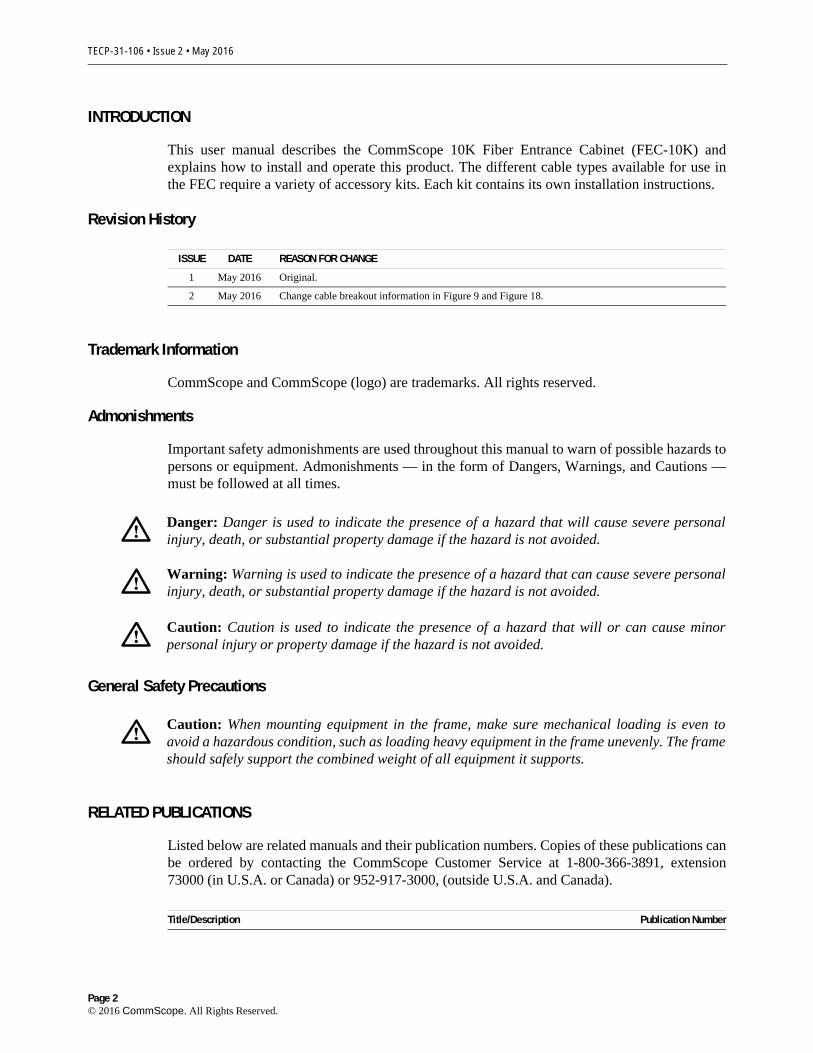
1 DESCRIPTION
The Fiber Entrance Cabinet (FEC-10K), shown in Figure 1 partly loaded and with door removed, is a high capacity wall- or strut-mounted splicing cabinet that accommodates up to 10,368 fiber cable splices.
Figure 1. FEC-1OK Front View With Door Removed
Page 3© 2016 CommScope. All Rights Reserved.
TECP-31-106 • Issue 2 • May 2016
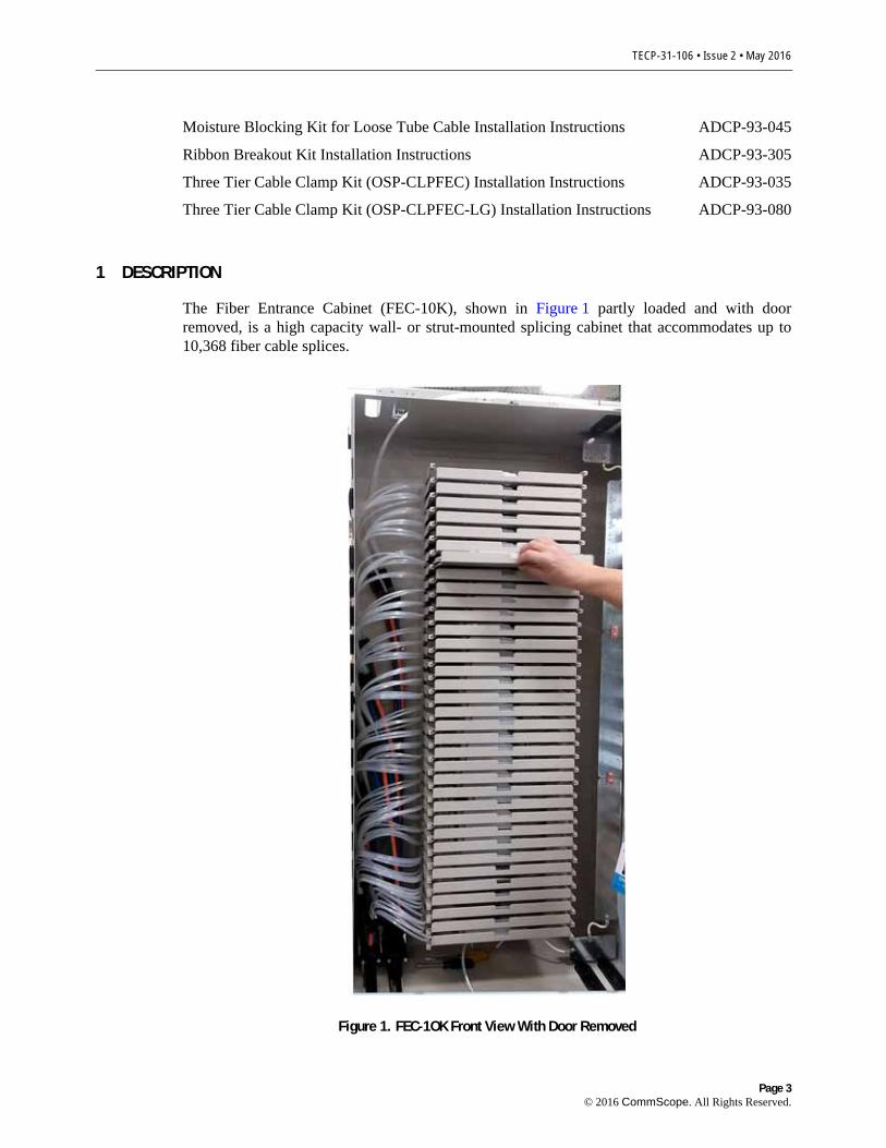
The FEC is designed for applications requiring an interface for Intra Facility Cable (IFC) and Outside Plant (OSP) cable. The FEC-10K provides storage and protection in addition to splicing. The conventional splice drawer employed in the FEC-10K provides service loop storage which allows splicing away from the FEC. Cable access ports are located at the top, bottom, and both sides of the cabinet. Pre-formed rubber grommets are provided in each cable access port. The grommets have micro slits that can be easily cut out to match cable diameter. Each grommet can handle up to three cables. Terminating and grounding plates provide cable clamp and ground connection points for IFC/OSP cables. The door hinges are split and allow the door to be removed for full access to the cabinet. The door is secured with over-center draw latches that are designed to accommodate padlocks for additional security.
Figure 2 shows the interior components of the FEC-10K. As shown, there are six top or bottom access ports for OSP cable entry and 36 side access ports for IFC cable entry. The FEC-10K comes with field installable cable mounting and ground brackets for the OSP cable and IFC cables, and six OSP cable clamps for cables up to 1.5" in diameter. As also shown, the FEC-10K has 36 splice drawers, each of which accommodates up to 288 splices.
REMOVABLEDOOR
26235-A
SPLICEDRAWER
(36X)
IFC CABLEENTRY
GROMMETS(18X)AND
PORTS(36X)
MOUNTINGBRACKET
(2X)
OSP CABLE ENTRY GROMMETS (2X)AND PORTS (6X)(4 LOCATIONS)
Figure 2. FEC-1OK Main Components
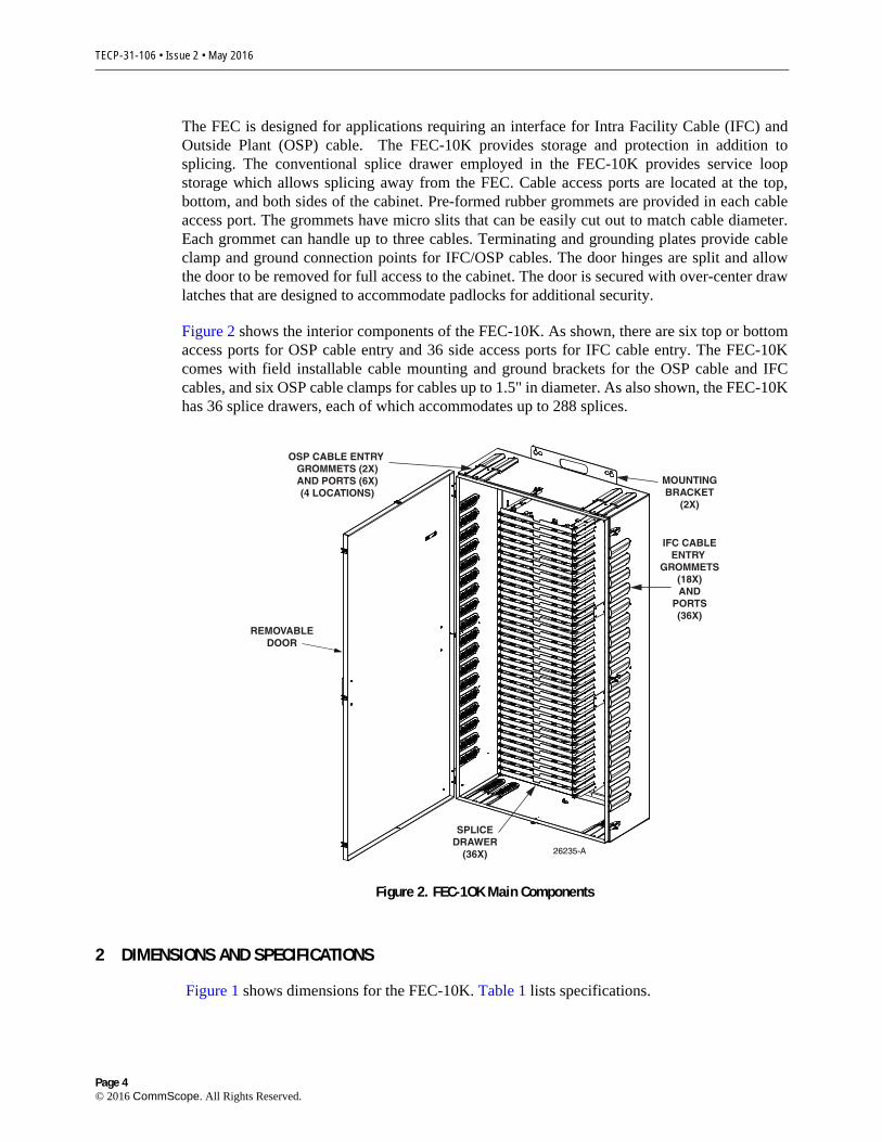
2 DIMENSIONS AND SPECIFICATIONS
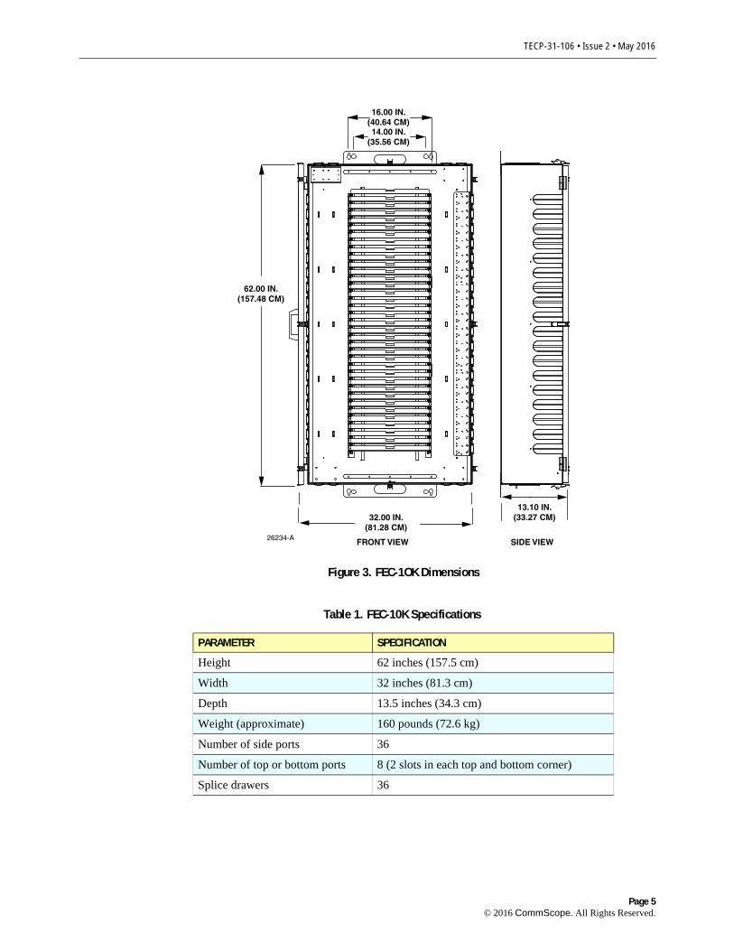
Figure 1 shows dimensions for the FEC-10K. Table 1 lists specifications.
Page 4© 2016 CommScope. All Rights Reserved.
TECP-31-106 • Issue 2 • May 2016
26234-A FRONT VIEW
62.00 IN.(157.48 CM)
16.00 IN.(40.64 CM)14.00 IN.
(35.56 CM)
SIDE VIEW
13.10 IN.(33.27 CM)32.00 IN.
(81.28 CM)
Figure 3. FEC-1OK Dimensions
Table 1. FEC-10K Specifications
PARAMETER SPECIFICATION
Height 62 inches (157.5 cm)
Width 32 inches (81.3 cm)
Depth 13.5 inches (34.3 cm)
Weight (approximate) 160 pounds (72.6 kg)
Number of side ports 36
Number of top or bottom ports 8 (2 slots in each top and bottom corner)
Splice drawers 36
Page 5© 2016 CommScope. All Rights Reserved.
TECP-31-106 • Issue 2 • May 2016
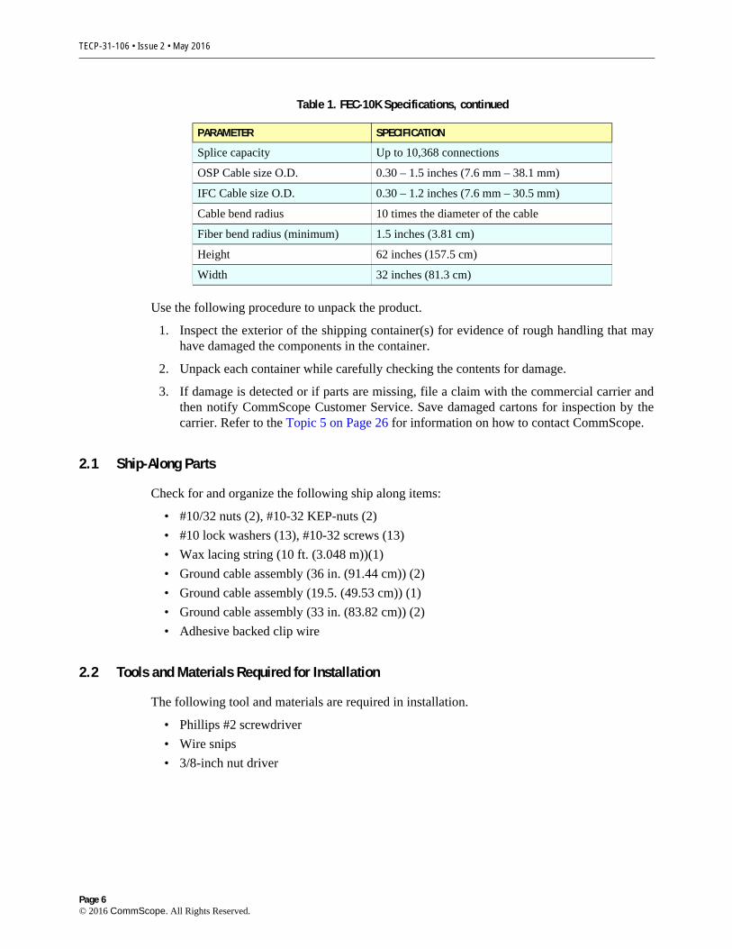
Use the following procedure to unpack the product.
1. Inspect the exterior of the shipping container(s) for evidence of rough handling that may have damaged the components in the container.
2. Unpack each container while carefully checking the contents for damage.
3. If damage is detected or if parts are missing, file a claim with the commercial carrier and then notify CommScope Customer Service. Save damaged cartons for inspection by the carrier. Refer to the Topic 5 on Page 26 for information on how to contact CommScope.
2.1 Ship-Along Parts
Check for and organize the following ship along items:
• #10/32 nuts (2), #10-32 KEP-nuts (2)
• #10 lock washers (13), #10-32 screws (13)
• Wax lacing string (10 ft. (3.048 m))(1)
• Ground cable assembly (36 in. (91.44 cm)) (2)
• Ground cable assembly (19.5. (49.53 cm)) (1)
• Ground cable assembly (33 in. (83.82 cm)) (2)
• Adhesive backed clip wire
2.2 Tools and Materials Required for Installation
The following tool and materials are required in installation.
• Phillips #2 screwdriver
• Wire snips
• 3/8-inch nut driver
Splice capacity Up to 10,368 connections
OSP Cable size O.D. 0.30 – 1.5 inches (7.6 mm – 38.1 mm)
IFC Cable size O.D. 0.30 – 1.2 inches (7.6 mm – 30.5 mm)
Cable bend radius 10 times the diameter of the cable
Fiber bend radius (minimum) 1.5 inches (3.81 cm)
Height 62 inches (157.5 cm)
Width 32 inches (81.3 cm)
Table 1. FEC-10K Specifications, continued
PARAMETER SPECIFICATION
Page 6© 2016 CommScope. All Rights Reserved.
TECP-31-106 • Issue 2 • May 2016
3 INSTALLATION PROCEDURE
Table 2 lists the main activities in installing the FEC-10K, and tells where you can find the associated procedures in this user manual.
Complete each activity before proceeding to the next activity in the table.
Table 2. Main Activities in Installing the FEC-10K
STEP ACTIVITY AND ASSOCIATED TOPIC AND PAGE TOPIC
1 Select cable configuration; move mounting plates if required Topic 3.1 on Page 7
2 Mount the FEC on a wall or on Unistrut Topic 3.2 on Page 9
4 Break out and install Outside Plant (OSP) cables Topic 3.3 on Page 12
5 Break out and install Intra Facility (IFC) cables Topic 3.4 on Page 22
6 Load splice trays and splice OSP and IFC fibers Topic 3.5 on Page 25
3.1 Select Cable Configuration; Move Mounting Plates if Required
Use the following procedure to select cable configuration and reconfigure the cabinet if necessary:
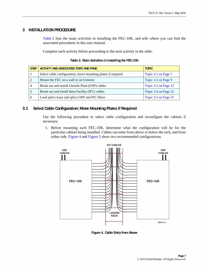
1. Before mounting each FEC-10K, determine what the configuration will be for the particular cabinet being installed. Cables can enter from above or below the rack, and from either side. Figure 4 and Figure 5 show two recommended configurations.
OSPCABLES
OSPCABLES
FEC-10K FEC-10K
26244-A
IFC CABLES
LADDERRACK
Figure 4. Cable Entry from Above
Page 7© 2016 CommScope. All Rights Reserved.
TECP-31-106 • Issue 2 • May 2016
OSPCABLES
FEC-10K FEC-10K
26321-A
OSPCABLES
IFC CABLES
LADDERRACK
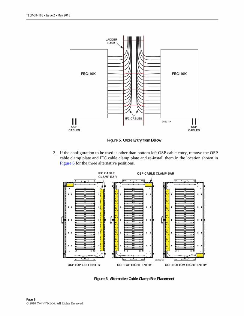
Figure 5. Cable Entry from Below
2. If the configuration to be used is other than bottom left OSP cable entry, remove the OSP cable clamp plate and IFC cable clamp plate and re-install them in the location shown in Figure 6 for the three alternative positions.
26252-A
OSP TOP LEFT ENTRY
IFC CABLECLAMP BAR
OSP CABLE CLAMP BAR
OSP TOP RIGHT ENTRY OSP BOTTOM RIGHT ENTRY
Figure 6. Alternative Cable Clamp Bar Placement
Page 8© 2016 CommScope. All Rights Reserved.

TECP-31-106 • Issue 2 • May 2016
3.2 Mount the FEC on a Wall or on Unitstrut
The FEC may be wall mounted or mounted to Unistrut. The mounting materials such as backboard, anchors, bolts, and Unistrut materials are not provided. Contact local support staff for their practices and recommendations for providing and using mounting materials. Select from the topics below to mount the FEC-10K using either Unistrut mounting or wall mounting.
3.2.1 Unistrut Mounting Procedure
Note: A CommScope Uni-bracket is required in the following procedure and must be separately ordered (catalog #FEC-UNIBKT: ACC BKT FEC UNISTRUT BLK).
Note: The vertical wall racks and Unistrut materials used in the following procedure are not provided and not available from CommScope. The Uni-bracket used in the procedure is available from CommScope but must be ordered separately (see Note above). It is recommended to use 0.50-inch (12.7 mm) and 0.25-inch (6.35 mm) size bolts and spring nuts.
Use the following instructions to mount the cabinet, referring to Figure 7.
UNISTRUTCHANNEL
BARS
WALL RACKS
WALL RACKUNI-BRACKET
WALLRACK
SPRINGNUT
UNISTRUTCHANNEL
BAR
WALL RACKUNI-BRACKET
SIDE VIEW
26258-A
Figure 7. Unistrut Mounted FEC-288
Page 9© 2016 CommScope. All Rights Reserved.

TECP-31-106 • Issue 2 • May 2016
1. Determine the location for the cabinet and insert the Uni-brackets in the wall rack.
2. Locate the spring nuts at the approximate position of the Uni-bracket hole and the FEC mounting holes.
3. Insert the Unistrut channel bars through the Uni-brackets.
4. Thread a 0.50-inch (12.7 mm) mounting bolt through each Uni-bracket into the Unistrut spring nuts. Align the Unistrut channel bars and tighten the bolts.
5. Place two 0.25-inch (6.35 mm) Unistrut spring nuts into the top Unistrut channel bar. Thread two 0.25-inch (6.35 mm) mounting bolts into the Unistrut spring nuts.
6. Place the FEC top mounting holes (keyholes) over the bolts. Position the FEC and tighten the bolts.
7. Place two 0.25-inch (6.35 mm) Unistrut spring nuts into the bottom Unistrut channel bar. Thread two 0.25-inch (6.35 mm) mounting bolts through the FEC bottom mounting holes into the Unistrut spring nuts and tighten.
8. Prepare a ground lead from central office ground to the FEC. Use #6 AWG wire and attach to a two hole crimp type lug (wire and lug not provided). Connect to the ground posts at the bottom of the FEC.
9. Attach cable designation labels on each splice drawer for IFC and OSP cable assignments.
3.2.2 Wall Mounting Procedure
The FEC may be mounted on a stable flat vertical surface. A backboard material (not provided) such as 0.75-inch (1.9 cm) thick plywood, applied to a wall provides a suitable mounting surface. The choice of fasteners is governed by local practice. Use, as a minimum, 0.375-inch (9.5 mm) diameter lag bolts and/or anchors.
If mounting on a hollow frame, wall backboard on both sides and through bolts are recommended. If the FEC is mounted directly to a concrete wall with anchors, ensure that the wall is straight so that when the fasteners are tightened the cabinet shape is not distorted. Shims may be required.
The door must fit square to provide a water resistant seal. The position of the FEC must allow enough space on all sides to bring the fiber cables in with out exceeding the minimum bend radius for the cable. The standard rule for cable bend radius is, the bend radius should be equal to or greater than ten times the cable diameter.
When determining the wall mounting locations, consider the following recommendations:
• Place cable racks a minimum of 10 inches (25.4 cm) from each side of the FEC-10K.
• Use 10-inch (25.4 cm) cable rack for FEC-10K cabinets.
• Allow at least 24 inches (61 cm) from the floor to the bottom of the FEC-864 cabinet.
• Do not stack FEC-10K cabinets.
Page 10© 2016 CommScope. All Rights Reserved.
TECP-31-106 • Issue 2 • May 2016
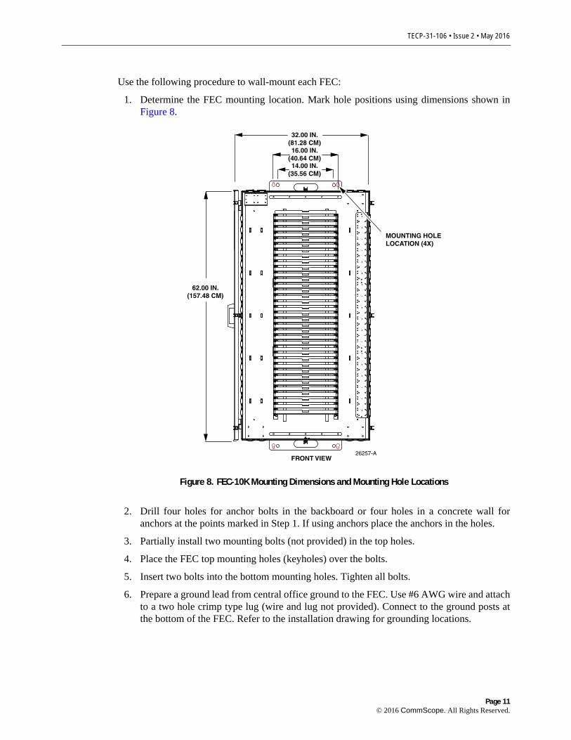
Use the following procedure to wall-mount each FEC:
1. Determine the FEC mounting location. Mark hole positions using dimensions shown in Figure 8.
26257-A
FRONT VIEW
62.00 IN.(157.48 CM)
16.00 IN.(40.64 CM)14.00 IN.
(35.56 CM)
32.00 IN.(81.28 CM)
MOUNTING HOLE LOCATION (4X)
Figure 8. FEC-10K Mounting Dimensions and Mounting Hole Locations
2. Drill four holes for anchor bolts in the backboard or four holes in a concrete wall for anchors at the points marked in Step 1. If using anchors place the anchors in the holes.
3. Partially install two mounting bolts (not provided) in the top holes.
4. Place the FEC top mounting holes (keyholes) over the bolts.
5. Insert two bolts into the bottom mounting holes. Tighten all bolts.
6. Prepare a ground lead from central office ground to the FEC. Use #6 AWG wire and attach to a two hole crimp type lug (wire and lug not provided). Connect to the ground posts at the bottom of the FEC. Refer to the installation drawing for grounding locations.
Page 11© 2016 CommScope. All Rights Reserved.

TECP-31-106 • Issue 2 • May 2016
3.3 Break Out and Install Outside Plant (OSP) Cables
Danger: Do not look into the ends of any optic fiber. Exposure to invisible radiation may result. Do not assume laser power is turned off or the fiber is disconnected at the other end.
Up to six OSP cables are terminated at the FEC-10K. Each cable has 1728 fibers divided into four sub-units each with 432 fibers. Each sub-unit is broken out into six furcation tubes each with 72 fibers.
These six furcation tubes are routed to two splice drawers, each of which accommodates 288 fibers. Refer to Figure 9, Figure 12, Figure 15, and Figure 14 for left top, left bottom, right top, and right bottom cable entry, respectively.
Refer to Figure 9 and Table 3 on Page 17 for OSP cable breakout dimensions. Note that, for any cable, the blue and orange sub-units have a different dimension than the green and brown sub-units (which are shorter). Also, note that furcation tubes are the same length for all cables and splice trays.
Note: Splice Drawer number in Table 3 starts at “1” with the first drawer loaded. This will be the top splice drawer for a bottom entry application, and the bottom splice drawer for a top entry application.
Note: All Sub-Unit Length dimensions given in Table 3 have a tolerance of -0/+2 in. (5.08 cm).
26273-A
GREEN & BROWNSUB-UNITS
BREAKOUT LENGTH‘A’ +0.0 IN./-6.0 IN. (+0.0 CM/-15.2 CM)
NOTE: BUFFER TUBE LENGTH AND RIBBON LENGTH ARE
THE SAME FOR ALL CABLE SUB-UNITS AND FOR ALL
INDIVIDUAL OSP BUFFER TUBES IN THIS APPLICATION.
BLUE & ORANGESUB-UNITSBREAKOUT
LENGTH‘A’ +0.0 IN./-6.0 IN.(+0.0 CM/-15.2 CM)
FURCATIONTUBE
LENGTH80 IN. (203.2 CM)-0.0 IN./+2.0 IN.
(-0.0 CM/+5.08 CM)
RIBBONLENGTH
(IN TOTAL)116 IN. (294.64 CM)
+/- 2.0 IN.(+/- 5.08 CM)
TO BE TRIMMED AT SPLICE
x
DRAWERTIE OFFPOINT
21 IN. (53.34 CM)+/- 1.0 IN.
(+/- 2.54 CM)
NOTE: THIS SYMBOLREPRESENTS THECABLE SUB-UNITBREAKOUT INSTALLED PER ADCP-93-305
Figure 9. OSP Cable Breakout Dimensions
Page 12© 2016 CommScope. All Rights Reserved.
TECP-31-106 • Issue 2 • May 2016
26249-A
CABLE 1 TRAYS
CABLE 6 TRAYS
CABLE 5 TRAYS
CABLE 4 TRAYS
1
2
CABLE 2 TRAYS
CABLE 3 TRAYS
45
6
FANOUTOF
TUBES(SIXPER
MODULE,TOTAL
DIVIDED INTO FOURPER
SPLCETRAY)
3
NOTE: CABLECOLORHERE IS
FORCLARITY
ONLY,DOES NOT
REPRESENTREAL
CABLECOLOR.
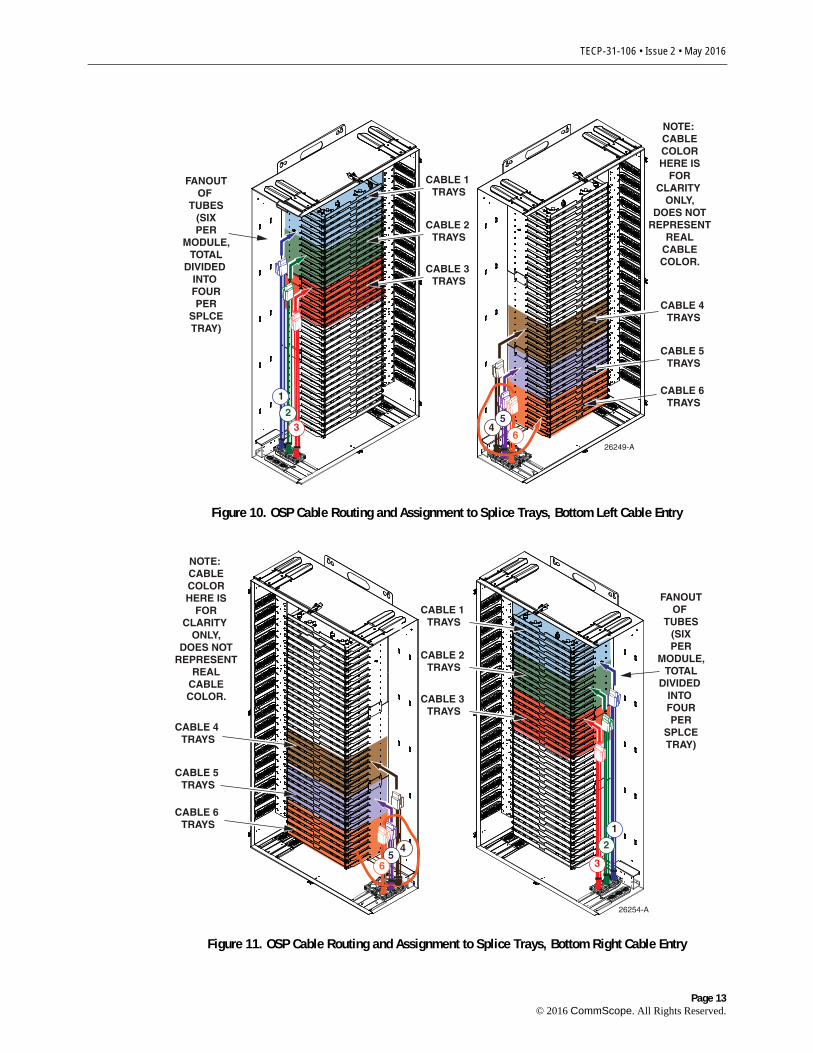
Figure 10. OSP Cable Routing and Assignment to Splice Trays, Bottom Left Cable Entry
26254-A
CABLE 1 TRAYS
CABLE 6 TRAYS
CABLE 5 TRAYS
CABLE 4 TRAYS
1
CABLE 2 TRAYS
CABLE 3 TRAYS
45
6
FANOUTOF
TUBES(SIXPER
MODULE,TOTAL
DIVIDED INTO FOURPER
SPLCETRAY)
2
3
NOTE: CABLECOLORHERE IS
FORCLARITY
ONLY,DOES NOT
REPRESENTREAL
CABLECOLOR.
Figure 11. OSP Cable Routing and Assignment to Splice Trays, Bottom Right Cable Entry
Page 13© 2016 CommScope. All Rights Reserved.
TECP-31-106 • Issue 2 • May 2016
26247-ACABLE 2
TRAYS
CABLE 3 TRAYS
CABLE 4 TRAYS
CABLE 5 TRAYS
CABLE 6 TRAYS
1 2
3
4 5
6
FANOUTOF
TUBES(SIXPER
MODULE,TOTAL
DIVIDED INTO FOURPER
SPLCETRAY)
NOTE: CABLECOLORHERE IS
FORCLARITY
ONLY,DOES NOT
REPRESENTREAL
CABLECOLOR.CABLE 1
TRAYS
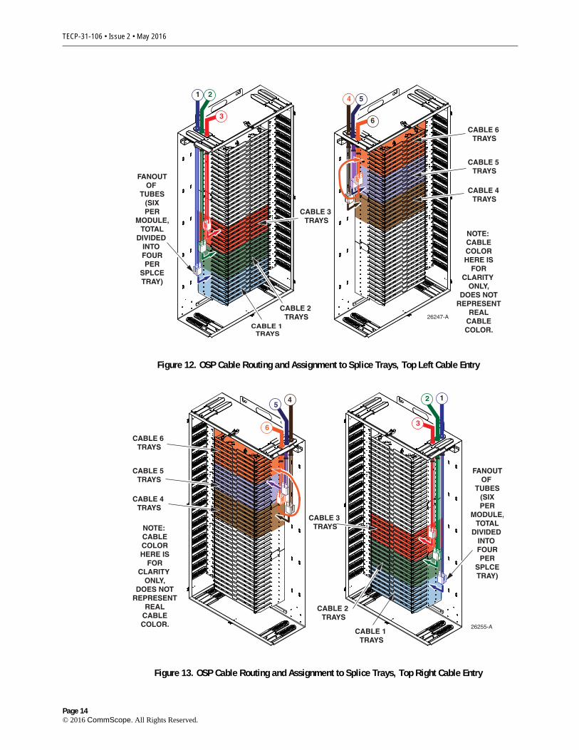
Figure 12. OSP Cable Routing and Assignment to Splice Trays, Top Left Cable Entry
CABLE 1 TRAYS
26255-A
CABLE 2 TRAYS
CABLE 3 TRAYS
CABLE 4 TRAYS
CABLE 5 TRAYS
CABLE 6 TRAYS
12
36
54
FANOUTOF
TUBES(SIXPER
MODULE,TOTAL
DIVIDED INTO FOURPER
SPLCETRAY)
NOTE: CABLECOLORHERE IS
FORCLARITY
ONLY,DOES NOT
REPRESENTREAL
CABLECOLOR.
Figure 13. OSP Cable Routing and Assignment to Splice Trays, Top Right Cable Entry
Page 14© 2016 CommScope. All Rights Reserved.
TECP-31-106 • Issue 2 • May 2016
1. On a work table adjacent to the cabinet, prepare a quantity of 144 ‘B’ size furcation Tubes (four per splice tray), as follows:
a. Cut all to the same length of 60 inches (152.4 cm) -0/+2 inches (5.08 cm).
b. Mark each furcation Tube at 20 inches (50.8 cm) from one end (this is the tie down point for the tube when routed into the splice tray).
c. Set aside the furcation Tubes for use as needed.
2. Route the first cable to the appropriate entry location shown in Figure 10, Figure 11, Figure 12, and Figure 10 for left top, left bottom, right top, or right bottom cable entry, respectively.
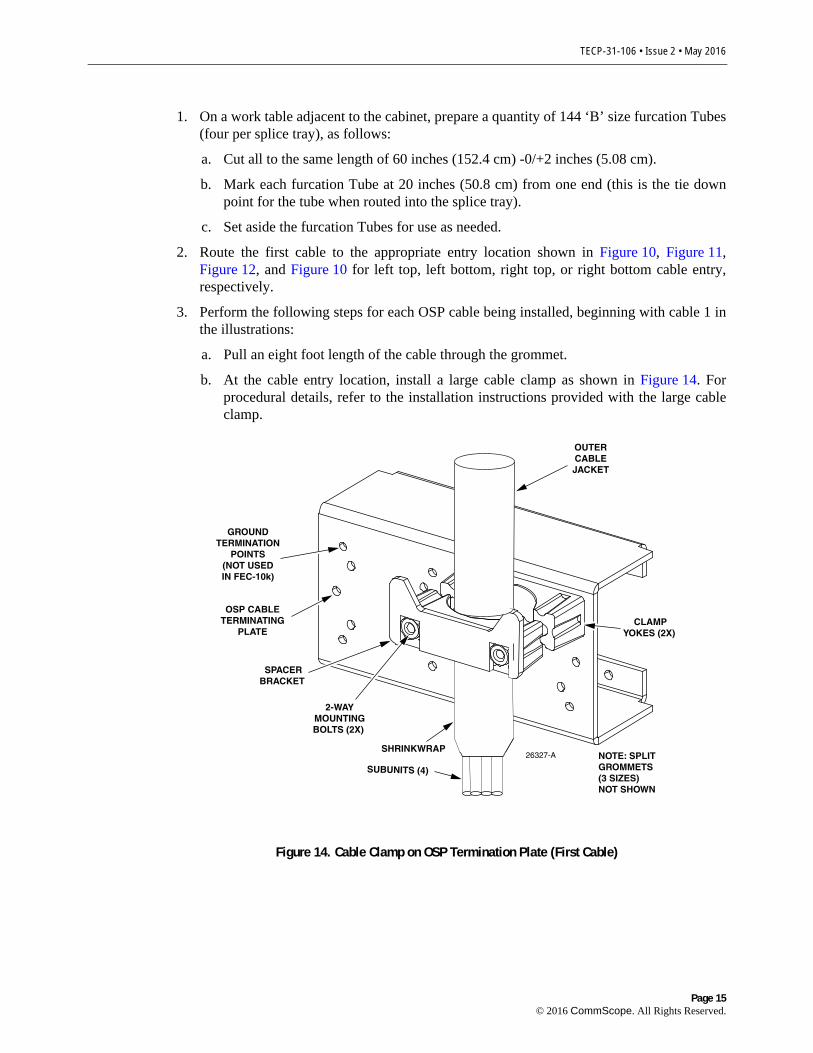
3. Perform the following steps for each OSP cable being installed, beginning with cable 1 in the illustrations:
a. Pull an eight foot length of the cable through the grommet.
b. At the cable entry location, install a large cable clamp as shown in Figure 14. For procedural details, refer to the installation instructions provided with the large cable clamp.
26327-ASHRINKWRAP
OSP CABLETERMINATING
PLATE
GROUNDTERMINATION
POINTS(NOT USEDIN FEC-10k)
OUTERCABLEJACKET
SUBUNITS (4)
SPACERBRACKET
CLAMPYOKES (2X)
2-WAYMOUNTINGBOLTS (2X)
NOTE: SPLITGROMMETS(3 SIZES)NOT SHOWN
Figure 14. Cable Clamp on OSP Termination Plate (First Cable)
Page 15© 2016 CommScope. All Rights Reserved.
TECP-31-106 • Issue 2 • May 2016
c. At a point 1.5 inches (3.81 cm) from the cable clamp (inside the cabinet), cut through the cable jacket and remove the cable jacket from the cable clamp to the stub end of the cable, thereby exposing the four inner sub-tubes (blue, orange, green, and brown in color).
Note: As successive cables are installed, overlay the furcation Tubes over those already installed so the furcation Tubes are laid in a neat leafing pattern from top to bottom for a top entry cable or bottom to top for a bottom entry cable.
d. Start with the first sub-unit (blue in color) and, referring to Table 3 on Page 17, measure out a section of length equal to the “A” dimension given for the blue subunit.
e. Strip off the sub-unit jacket at this location and thread the first six 12-fiber ribbons into protective tubes of the length prepared in Step 1. Place these protective tubes within a ribbon breakout kit, referring to publication ADCP-93-305, provided with the ribbon breakout kit. This will leave a section of exposed ribbons for use when installing splice trays.
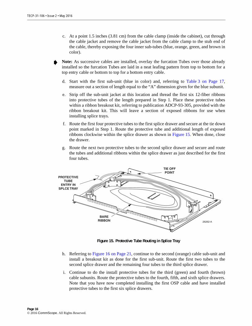
f. Route the first four protective tubes to the first splice drawer and secure at the tie down point marked in Step 1. Route the protective tube and additional length of exposed ribbons clockwise within the splice drawer as shown in Figure 15. When done, close the drawer.
g. Route the next two protective tubes to the second splice drawer and secure and route the tubes and additional ribbons within the splice drawer as just described for the first four tubes.
26262-A
PROTECTIVETUBE
ENTRY INSPLCE TRAY
TIE OFFPOINT
BARERIBBON
Figure 15. Protective Tube Routing in Splice Tray
h. Referring to Figure 16 on Page 21, continue to the second (orange) cable sub-unit and install a breakout kit as done for the first sub-unit. Route the first two tubes to the second splice drawer and the remaining four tubes to the third splice drawer.
i. Continue to do the install protective tubes for the third (green) and fourth (brown) cable subunits. Route the protective tubes to the fourth, fifth, and sixth splice drawers. Note that you have now completed installing the first OSP cable and have installed protective tubes to the first six splice drawers.
Page 16© 2016 CommScope. All Rights Reserved.
TECP-31-106 • Issue 2 • May 2016
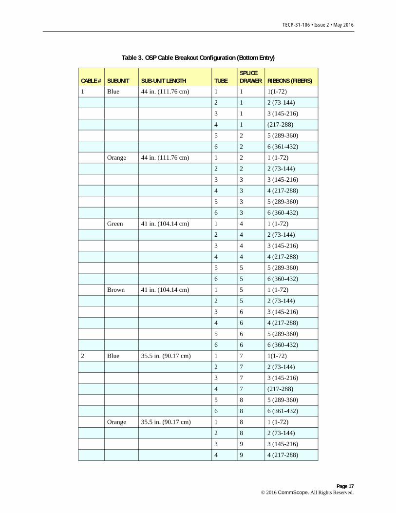
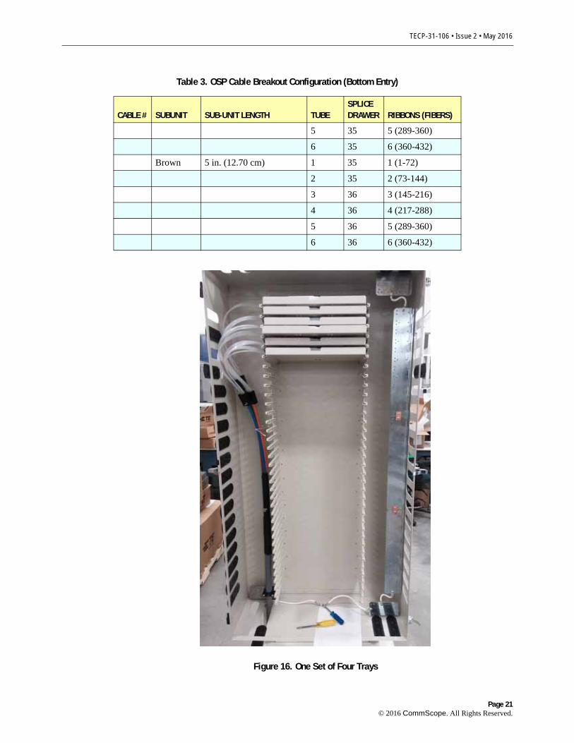
Table 3. OSP Cable Breakout Configuration (Bottom Entry)
CABLE # SUBUNIT SUB-UNIT LENGTH TUBESPLICE DRAWER RIBBONS (FIBERS)
1 Blue 44 in. (111.76 cm) 1 1 1(1-72)
2 1 2 (73-144)
3 1 3 (145-216)
4 1 (217-288)
5 2 5 (289-360)
6 2 6 (361-432)
Orange 44 in. (111.76 cm) 1 2 1 (1-72)
2 2 2 (73-144)
3 3 3 (145-216)
4 3 4 (217-288)
5 3 5 (289-360)
6 3 6 (360-432)
Green 41 in. (104.14 cm) 1 4 1 (1-72)
2 4 2 (73-144)
3 4 3 (145-216)
4 4 4 (217-288)
5 5 5 (289-360)
6 5 6 (360-432)
Brown 41 in. (104.14 cm) 1 5 1 (1-72)
2 5 2 (73-144)
3 6 3 (145-216)
4 6 4 (217-288)
5 6 5 (289-360)
6 6 6 (360-432)
2 Blue 35.5 in. (90.17 cm) 1 7 1(1-72)
2 7 2 (73-144)
3 7 3 (145-216)
4 7 (217-288)
5 8 5 (289-360)
6 8 6 (361-432)
Orange 35.5 in. (90.17 cm) 1 8 1 (1-72)
2 8 2 (73-144)
3 9 3 (145-216)
4 9 4 (217-288)
Page 17© 2016 CommScope. All Rights Reserved.
TECP-31-106 • Issue 2 • May 2016
5 9 5 (289-360)
6 9 6 (360-432)
Green 32.5 in. (82.55 cm) 1 10 1 (1-72)
2 10 2 (73-144)
3 10 3 (145-216)
4 10 4 (217-288)
5 11 5 (289-360)
6 11 6 (360-432)
Brown 32.5 in. (82.55 cm) 1 11 1 (1-72)
2 11 2 (73-144)
3 12 3 (145-216)
4 12 4 (217-288)
5 12 5 (289-360)
6 12 6 (360-432)
3 Blue 27 in, (68.58 cm) 1 13 1(1-72)
2 13 2 (73-144)
3 13 3 (145-216)
4 13 (217-288)
5 14 5 (289-360)
6 14 6 (361-432)
Orange 27 in, (68.58 cm) 1 14 1 (1-72)
2 14 2 (73-144)
3 15 3 (145-216)
4 15 4 (217-288)
5 15 5 (289-360)
6 15 6 (360-432)
Green 23 in. (58.42 cm) 1 16 1 (1-72)
2 16 2 (73-144)
3 16 3 (145-216)
4 16 4 (217-288)
5 17 5 (289-360)
6 17 6 (360-432)
Brown 23 in. (58.42 cm) 1 17 1 (1-72)
2 17 2 (73-144)
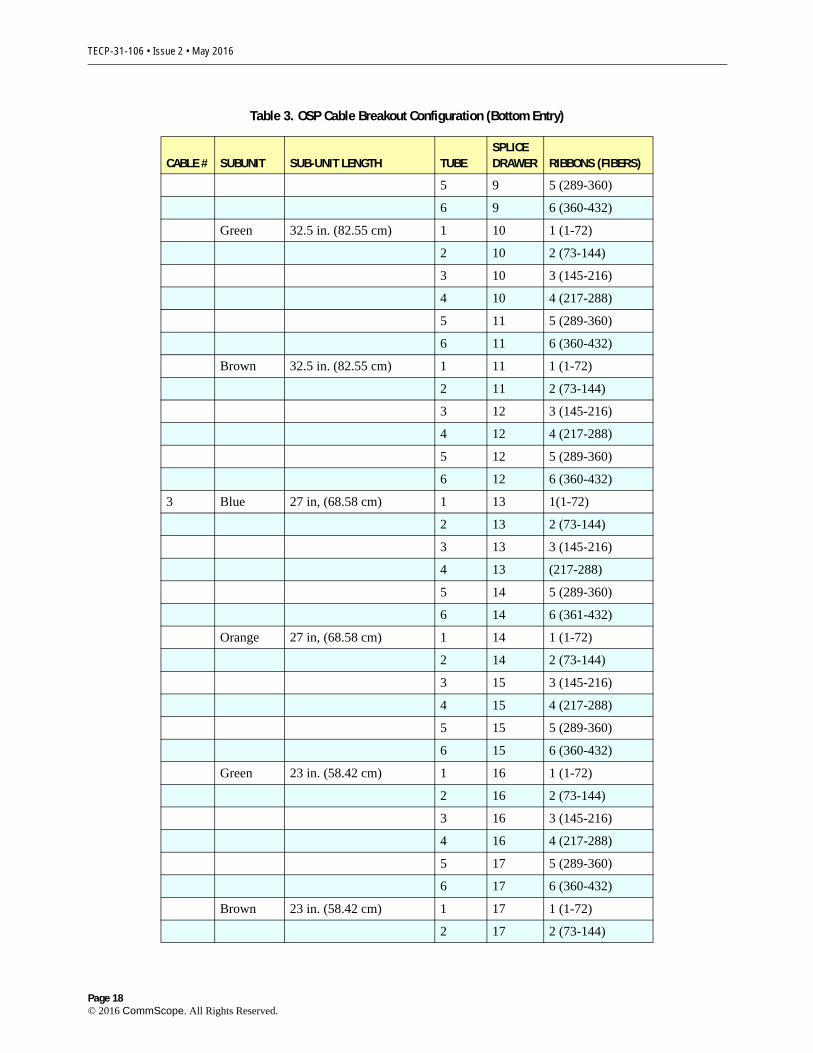
Table 3. OSP Cable Breakout Configuration (Bottom Entry)
CABLE # SUBUNIT SUB-UNIT LENGTH TUBESPLICE DRAWER RIBBONS (FIBERS)
Page 18© 2016 CommScope. All Rights Reserved.

TECP-31-106 • Issue 2 • May 2016
3 18 3 (145-216)
4 18 4 (217-288)
5 18 5 (289-360)
18 18 6 (360-432)
4 Blue 18.5 in. (46.99 cm) 1 19 1(1-72)
2 19 2 (73-144)
3 19 3 (145-216)
4 19 (217-288)
5 20 5 (289-360)
6 20 6 (361-432)
Orange 18.5 in. (46.99 cm) 1 20 1 (1-72)
2 20 2 (73-144)
3 21 3 (145-216)
4 21 4 (217-288)
5 21 5 (289-360)
6 21 6 (360-432)
Green 15.5 in. (39.37cm) 1 22 1 (1-72)
2 22 2 (73-144)
3 22 3 (145-216)
4 22 4 (217-288)
5 23 5 (289-360)
6 23 6 (360-432)
Brown 15.5 in. (39.37cm) 1 23 1 (1-72)
2 23 2 (73-144)
3 24 3 (145-216)
4 24 4 (217-288)
5 24 5 (289-360)
6 24 6 (360-432)
5 Blue 10 in. (25.54 cm) 1 25 1(1-72)
2 25 2 (73-144)
3 25 3 (145-216)
4 25 (217-288)
5 26 5 (289-360)
6 26 6 (361-432)
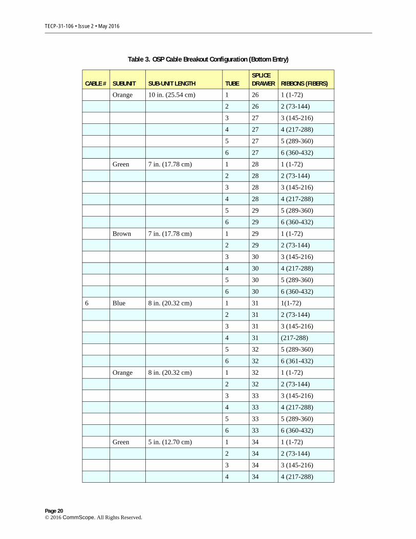
Table 3. OSP Cable Breakout Configuration (Bottom Entry)
CABLE # SUBUNIT SUB-UNIT LENGTH TUBESPLICE DRAWER RIBBONS (FIBERS)
Page 19© 2016 CommScope. All Rights Reserved.
TECP-31-106 • Issue 2 • May 2016
Orange 10 in. (25.54 cm) 1 26 1 (1-72)
2 26 2 (73-144)
3 27 3 (145-216)
4 27 4 (217-288)
5 27 5 (289-360)
6 27 6 (360-432)
Green 7 in. (17.78 cm) 1 28 1 (1-72)
2 28 2 (73-144)
3 28 3 (145-216)
4 28 4 (217-288)
5 29 5 (289-360)
6 29 6 (360-432)
Brown 7 in. (17.78 cm) 1 29 1 (1-72)
2 29 2 (73-144)
3 30 3 (145-216)
4 30 4 (217-288)
5 30 5 (289-360)
6 30 6 (360-432)
6 Blue 8 in. (20.32 cm) 1 31 1(1-72)
2 31 2 (73-144)
3 31 3 (145-216)
4 31 (217-288)
5 32 5 (289-360)
6 32 6 (361-432)
Orange 8 in. (20.32 cm) 1 32 1 (1-72)
2 32 2 (73-144)
3 33 3 (145-216)
4 33 4 (217-288)
5 33 5 (289-360)
6 33 6 (360-432)
Green 5 in. (12.70 cm) 1 34 1 (1-72)
2 34 2 (73-144)
3 34 3 (145-216)
4 34 4 (217-288)
Table 3. OSP Cable Breakout Configuration (Bottom Entry)
CABLE # SUBUNIT SUB-UNIT LENGTH TUBESPLICE DRAWER RIBBONS (FIBERS)
Page 20© 2016 CommScope. All Rights Reserved.
TECP-31-106 • Issue 2 • May 2016
Figure 16. One Set of Four Trays
5 35 5 (289-360)
6 35 6 (360-432)
Brown 5 in. (12.70 cm) 1 35 1 (1-72)
2 35 2 (73-144)
3 36 3 (145-216)
4 36 4 (217-288)
5 36 5 (289-360)
6 36 6 (360-432)
Table 3. OSP Cable Breakout Configuration (Bottom Entry)
CABLE # SUBUNIT SUB-UNIT LENGTH TUBESPLICE DRAWER RIBBONS (FIBERS)
Page 21© 2016 CommScope. All Rights Reserved.
TECP-31-106 • Issue 2 • May 2016
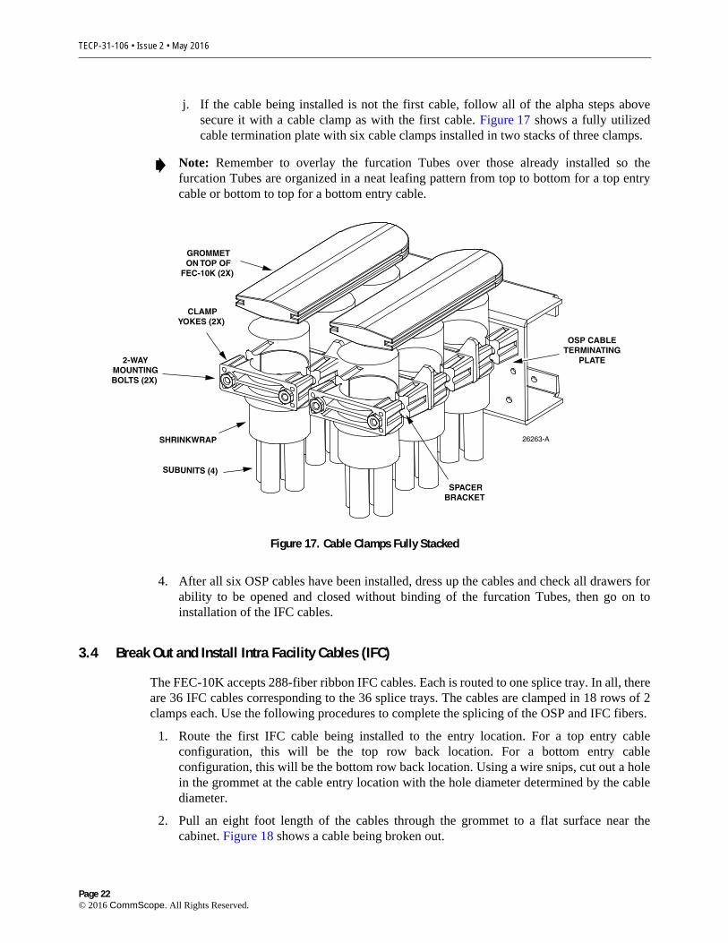
j. If the cable being installed is not the first cable, follow all of the alpha steps above secure it with a cable clamp as with the first cable. Figure 17 shows a fully utilized cable termination plate with six cable clamps installed in two stacks of three clamps.
Note: Remember to overlay the furcation Tubes over those already installed so the furcation Tubes are organized in a neat leafing pattern from top to bottom for a top entry cable or bottom to top for a bottom entry cable.
26263-ASHRINKWRAP
OSP CABLETERMINATING
PLATE
SUBUNITS (4)
SPACERBRACKET
CLAMPYOKES (2X)
2-WAYMOUNTINGBOLTS (2X)
GROMMETON TOP OF
FEC-10K (2X)
Figure 17. Cable Clamps Fully Stacked
4. After all six OSP cables have been installed, dress up the cables and check all drawers for ability to be opened and closed without binding of the furcation Tubes, then go on to installation of the IFC cables.
3.4 Break Out and Install Intra Facility Cables (IFC)
The FEC-10K accepts 288-fiber ribbon IFC cables. Each is routed to one splice tray. In all, there are 36 IFC cables corresponding to the 36 splice trays. The cables are clamped in 18 rows of 2 clamps each. Use the following procedures to complete the splicing of the OSP and IFC fibers.
1. Route the first IFC cable being installed to the entry location. For a top entry cable configuration, this will be the top row back location. For a bottom entry cable configuration, this will be the bottom row back location. Using a wire snips, cut out a hole in the grommet at the cable entry location with the hole diameter determined by the cable diameter.
2. Pull an eight foot length of the cables through the grommet to a flat surface near the cabinet. Figure 18 shows a cable being broken out.
Page 22© 2016 CommScope. All Rights Reserved.
TECP-31-106 • Issue 2 • May 2016
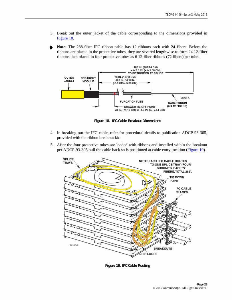
3. Break out the outer jacket of the cable corresponding to the dimensions provided in Figure 18.
Note: The 288-fiber IFC ribbon cable has 12 ribbons each with 24 fibers. Before the ribbons are placed in the protective tubes, they are severed lengthwise to form 24 12-fiber ribbons then placed in four protective tubes as 6 12-fiber ribbons (72 fibers) per tube.
26265-A
BREAKOUTMODULE
OUTERJACKET
FURCATION TUBE BARE RIBBON(6 X 12 FIBERS)
70 IN. (177.8 CM)-0.0 IN. /+2.0 IN.
(-0.0 CM/+ 5.08 CM)
106 IN. (269.24 CM)+ /- 2.0 IN. (+ /- 5.08 CM)
TO BE TRIMMED AT SPLICE
DRAWER TIE OFF POINT28 IN. (71.12 CM) +/- 1.0 IN. (+/- 2.54 CM)
x
Figure 18. IFC Cable Breakout Dimensions
4. In breaking out the IFC cable, refer for procedural details to publication ADCP-93-305, provided with the ribbon breakout kit.
5. After the four protective tubes are loaded with ribbons and installed within the breakout per ADCP-93-305 pull the cable back so is positioned at cable entry location (Figure 19).
SPLICETRAYS NOTE: EACH IFC CABLE ROUTES
TO ONE SPLICE TRAY (FOUR SUBUNITS, EACH 72 FIBERS, TOTAL 288).
26256-A
IFC CABLECLAMPS
DRIP LOOPS
BREAKOUTS
TIE DOWNPOINT
Figure 19. IFC Cable Routing
Page 23© 2016 CommScope. All Rights Reserved.
TECP-31-106 • Issue 2 • May 2016
6. Route the four tubes into the top splice tray (for top entry) or bottom (for bottom entry). Route the protective tube and additional length of exposed ribbons counter-clockwise within the splice drawer.
Note: Be careful to follow the correct color order when placing the ribbons in the tubes.
7. When routing the tubes into the splice tray, allow a drip loop to form as shown in Figure 19.
8. Continue to the next cable and repeat the same procedure in breaking out the cable. When clamping the cable, clamp it outside of the first clamp in a double stack configuration as shown.
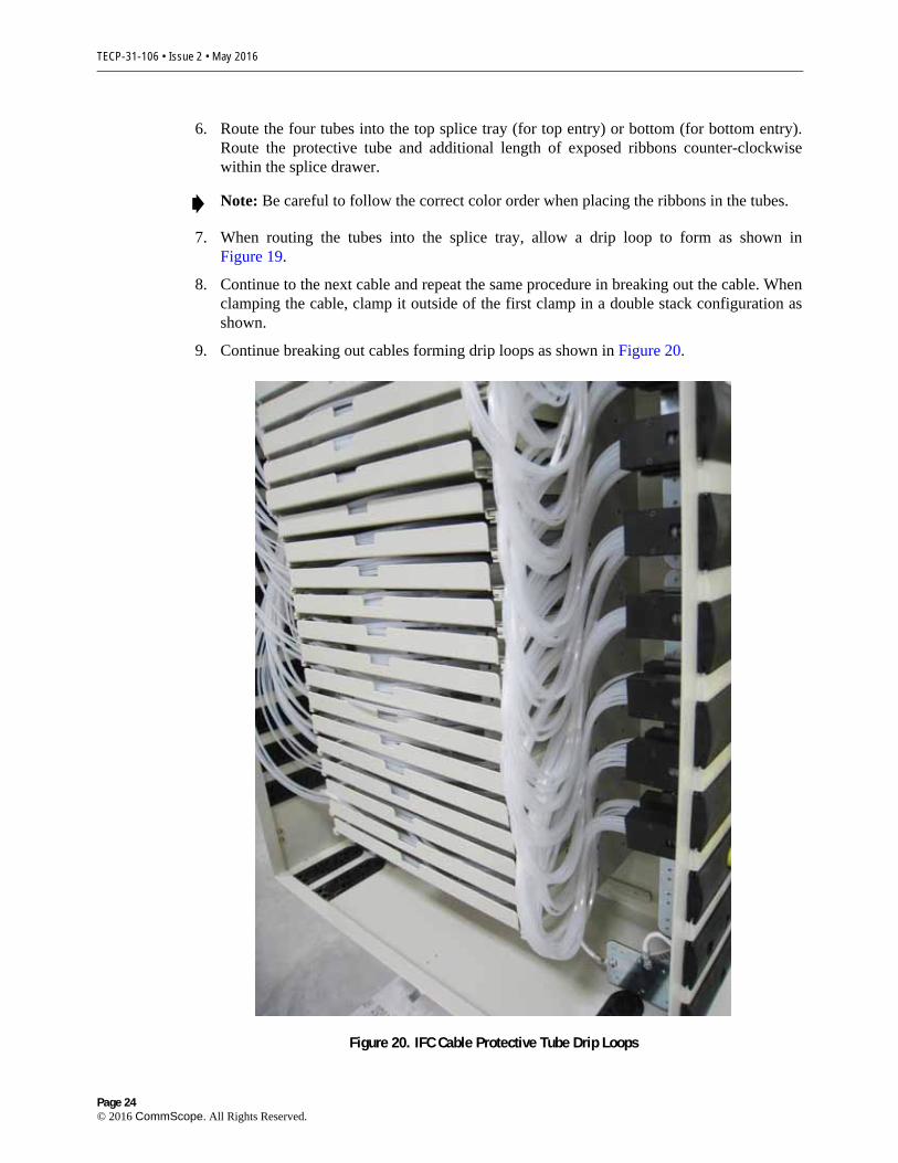
9. Continue breaking out cables forming drip loops as shown in Figure 20.
Figure 20. IFC Cable Protective Tube Drip Loops
Page 24© 2016 CommScope. All Rights Reserved.
TECP-31-106 • Issue 2 • May 2016
10. Continue preparing cables and loading splice trays until all of the input IFC cables have been installed and routed in a neat and orderly manner as shown.
3.5 Load Splice Drawers and Splice OSP and IFC Fibers
Danger: Do not look into the ends of any optic fiber. Exposure to invisible radiation may result. Do not assume laser power is turned off or the fiber is disconnected at the other end.
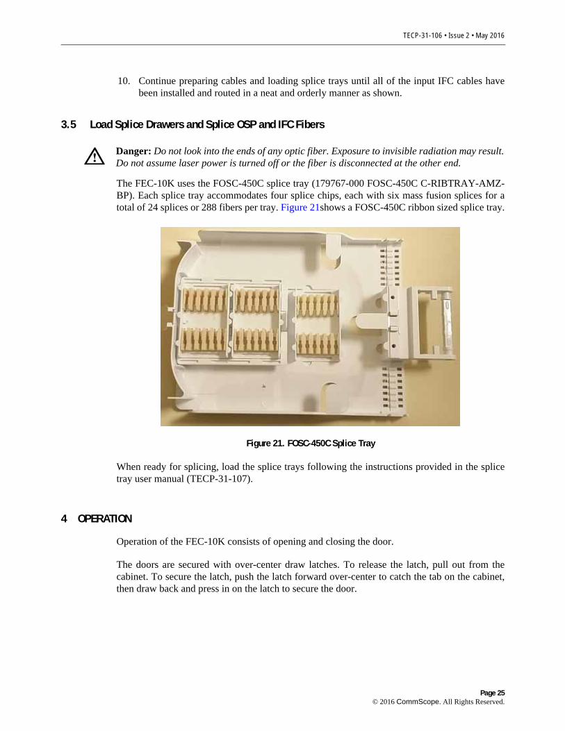
The FEC-10K uses the FOSC-450C splice tray (179767-000 FOSC-450C C-RIBTRAY-AMZ-BP). Each splice tray accommodates four splice chips, each with six mass fusion splices for a total of 24 splices or 288 fibers per tray. Figure 21shows a FOSC-450C ribbon sized splice tray.
Figure 21. FOSC-450C Splice Tray
When ready for splicing, load the splice trays following the instructions provided in the splice tray user manual (TECP-31-107).
4 OPERATION
Operation of the FEC-10K consists of opening and closing the door.
The doors are secured with over-center draw latches. To release the latch, pull out from the cabinet. To secure the latch, push the latch forward over-center to catch the tab on the cabinet, then draw back and press in on the latch to secure the door.
Page 25© 2016 CommScope. All Rights Reserved.

TECP-31-106 • Issue 2 • May 2016
5 CUSTOMER INFORMATION AND ASSISTANCE
For technical assistance for this product, call 1.800.830.5056. To email for technical service, use [email protected]. CommScope’s website address is www.commscope.com.
Page 26© 2016 CommScope. All Rights Reserved.