Embed Size (px)
Citation preview

EXPERTS FOR THE REAL WORLD
SINCE 1842
www.casece.com
CX C-SERIES HYDRAULIC EXCAVATORS
CX300C I CX350C I CX470C
TECHNOLOGY
YOU CAN TRUST

22
TECHNOLOGY
YOU CAN TRUST

3
CLEAN POWER
Case C Series excavators use clean and effi cient Tier 4 interim diesel engines.
Equipped with cooled exhaust gas recirculation (CEGR) and a diesel particulate fi lter, the engine is capable of
meeting emissions regulations without the need for additional diesel exhaust fl uids.
Automatic self-regeneration of the diesel particulate diffusor (DPD) ensures no loss of productivity, while low engine
rpm, improved hydraulic pump control and fi ve new energy saving systems boost fuel economy by up to 10%.
A green economy gauge can be activated in the cab to inform the operator of the most economical settings for the
machine, reporting fuel consumption in real-time.
4
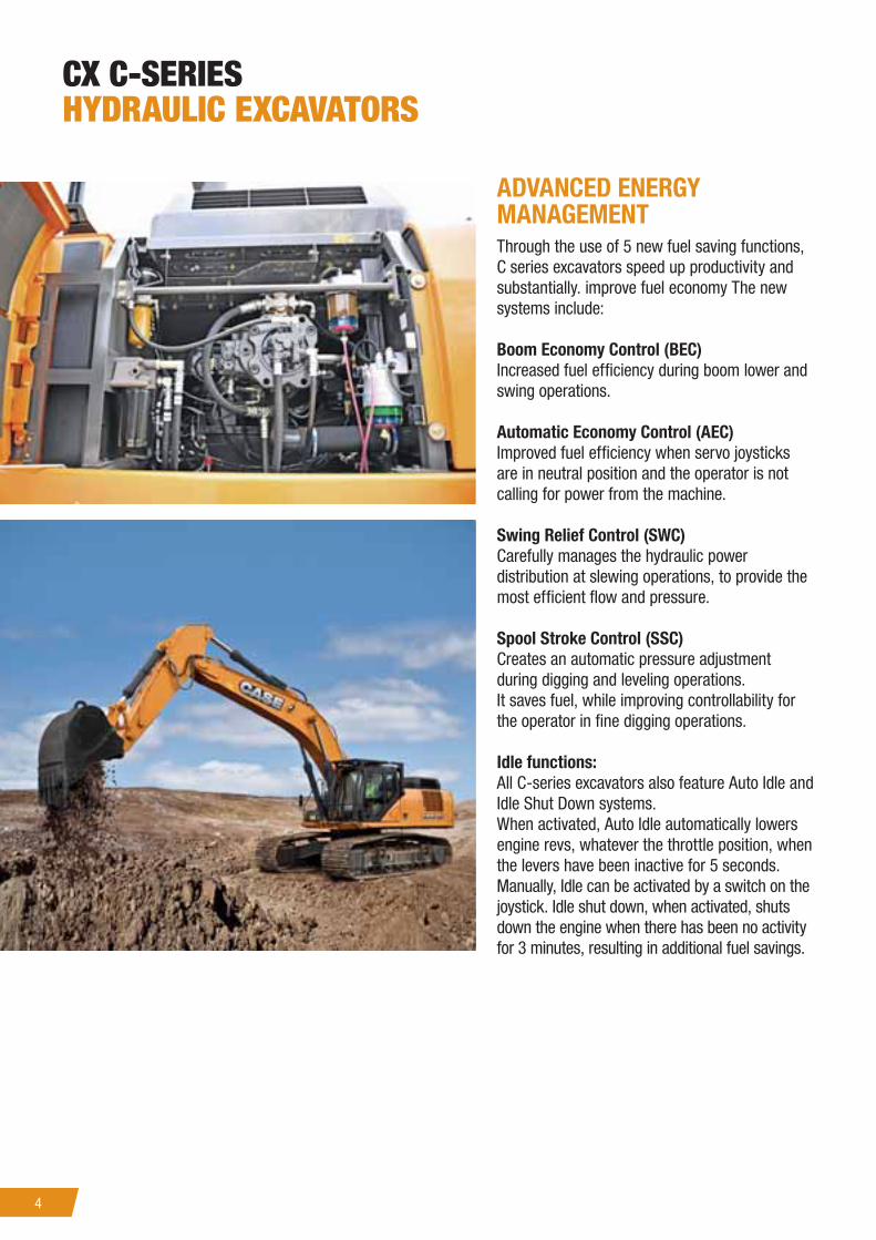
CX C-SERIES
HYDRAULIC EXCAVATORS
ADVANCED ENERGY
MANAGEMENT
Through the use of 5 new fuel saving functions,
C series excavators speed up productivity and
substantially. improve fuel economy The new
systems include:
Boom Economy Control (BEC)
Increased fuel effi ciency during boom lower and
swing operations.
Automatic Economy Control (AEC)
Improved fuel effi ciency when servo joysticks
are in neutral position and the operator is not
calling for power from the machine.
Swing Relief Control (SWC)
Carefully manages the hydraulic power
distribution at slewing operations, to provide the
most effi cient fl ow and pressure.
Spool Stroke Control (SSC)
Creates an automatic pressure adjustment
during digging and leveling operations.
It saves fuel, while improving controllability for
the operator in fi ne digging operations.
Idle functions:
All C-series excavators also feature Auto Idle and
Idle Shut Down systems.
When activated, Auto Idle automatically lowers
engine revs, whatever the throttle position, when
the levers have been inactive for 5 seconds.
Manually, Idle can be activated by a switch on the
joystick. Idle shut down, when activated, shuts
down the engine when there has been no activity
for 3 minutes, resulting in additional fuel savings.

5
INCREASED PRODUCTIVITY
As part of the Case Intelligent Hydraulic System all Case C Series excavators benefi t from improvements in
performance and productivity.
Lifting capacity is increased and cycle times have been cut. Individual operating weights are slightly increased to
cope with the additional digging and loading forces, ensuring stable, consistent high production for the customer.
Bucket and boom down regeneration systems feed hydraulic oil back to the supply side of the pump, reducing the
requirement for engine power.
The C Series excavators use the familiar working mode control from the B Series machines, making it easy for the
operator to become familiar with the new models. The Super Power Mode provides a 5% boost when required for
maximum digging ability.
The new monitor in the C Series machines provides operators with the chance to pre-programme auxiliary hydraulic
fl ow and power settings (option) for up to 10 attachments, providing rapid changeover and increased productivity.

6
CX C-SERIES
HYDRAULIC EXCAVATORS
TIER 4 INTERIM - CLEAN & EFFICIENT
The new Isuzu 6-cylinder engine meets EPA’s Tier 4 interim without a need for additional diesel exhaust fl uid.
The cooled exhaust gas recirculation (CEGR) in triple layer design effectively reduces NOx while PM is reduced by a
diesel particulate fi lter (DPF) in combination with the variable geometry turbocharger.
A diesel oxidation catalyst (DOC) treats carbon monoxide , hydrocarbons and other compounds. Both components
are integrated in the DPD (Diesel Particle Diffusor). Automatic self regeneration speeds your productivity - you can
go on working as usual without stopping for the regeneration process of the particle diffusor.
A look under the hood immediately confi rms an extremely effi cient use of space: the engine, the cooling system
and the exhaust system are all designed and grouped so as to take advantage of all the available space, while also
granting excellent serviceability and operator visibility
Low engine rpm in combination with further improved pump torque control and further 5 new energy saving
systems reduces the fuel consumption further by up to 10%.
A ECO gauge on can be activated on the new multifunction screen to inform you instantly about the key parameters
concerning fuel economy and fuel consumption. Side by side coolers, intercooler and the fuel cooler are now even
more effi cient thus further increasing our well appreciated durability.

7
FIRST CLASS SERVICEABILITY
All fi lters and regular fi ll points are grouped for easy access, with engine
oil change intervals set at 500 hours. A synthetic fi lter is used for the
hydraulic oil, providing 5,000 hour intervals, and all pins and bushes
(except the bucket pin) use the Case Extended Maintenance System
bushings, allowing greasing intervals of up to 1,000 hours.
The radiator and cooler cores are mounted side by side, to allow easy
access for cleaning and more effi cient cooling. A 100 litre/min refuelling
pump with automatic cut off is provided as standard, reducing downtime
for regular fi lls.
The Japanese-built Case excavators boast an enviable reputation for
reliability and durability, which looks set to continue with the new C Series
of CX class crawler excavators.
8
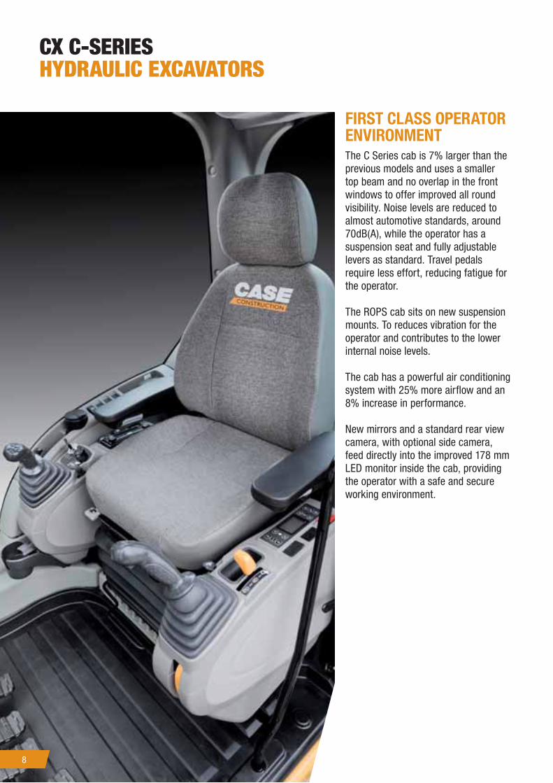
FIRST CLASS OPERATOR
ENVIRONMENT
The C Series cab is 7% larger than the
previous models and uses a smaller
top beam and no overlap in the front
windows to offer improved all round
visibility. Noise levels are reduced to
almost automotive standards, around
70dB(A), while the operator has a
suspension seat and fully adjustable
levers as standard. Travel pedals
require less effort, reducing fatigue for
the operator.
The ROPS cab sits on new suspension
mounts. To reduces vibration for the
operator and contributes to the lower
internal noise levels.
The cab has a powerful air conditioning
system with 25% more airfl ow and an
8% increase in performance.
New mirrors and a standard rear view
camera, with optional side camera,
feed directly into the improved 178 mm
LED monitor inside the cab, providing
the operator with a safe and secure
working environment.
CX C-SERIES
HYDRAULIC EXCAVATORS

9
FULL COLOUR
MULTIFUNCTION MONITOR
The standard 178 mm LED monitor provides all of the
information that the operator needs at a glance. Easy
to use buttons guide the operator through the screen
functions and the monitor can be split to show the
standard rear view, and optional side view camera images.
Information includes working mode, travel speed, working
lights, attachment choice, time and working hours,
along with system data such as coolant and hydraulic
oil temperatures, fuel level and the condition of the
particulate fi lter and the auto-regeneration function.
When selected, the ECO gauge displays the function of the
various energy saving systems, allowing the operator to
maximise effi ciency and save fuel.
The monitor can be set to work in one of 20 languages,
and is also used by service technicians to access onboard
diagnostic functions.

10
THE CASE DEALER: YOUR PROFESSIONAL PARTNER
Your success starts with world-class Case machinery and attachments.
Your Case dealer will help you work smarter and faster by selecting equipment that delivers performance and
operator comfort.
Your dealer has the knowledge and experience necessary to help you choose the right attachments so you can…
• Work faster and extend equipment life.
• Increase machine utilization.
• Increase your capabilities.
Let your Case dealer service your machine on the jobsite.
You’ll be back on the job faster.
Advantages include…
• Responsive job site service to keep your equipment running.
• Increase machine uptime.
• Certifi ed service staff and improved parts availability.

11
PARTS
When you’re looking for superior parts options to maximize the performance and lower the operating costs of your
Case machinery, turn to CNH Industrial Genuine Parts to keep you equipped for success.
CNH Industrial Genuine Parts fi t better, install faster and last longer and in an industry where “high impact” and
“heavy lifting” are the norm, the smallest mechanical differences can lead to big problems.
CNH Industrial Genuine Parts from Case are manufactured from superior materials and specifi cally designed for
Case construction equipment to continually and reliably withstand the punishment of everyday construction. So
steer clear of mechanical problems and future breakdowns, by choosing CNH Industrial Genuine Parts from Case.
They’re the only parts that are fi eld-tested and proven to keep your Case equipment performing its best.
SERVICE. RELY ON CASE TO DELIVER FOR YOU
Your commitment to your operation is evident every day, but that doesn’t minimize the enormous pressure you
face to reduce operating costs and improve productivity. So when you’re on the job, make sure you have top-notch
service and support of Case behind you every step of the way.
With our factory trained technicians, you can ensure that top-notch service professionals are working on your
maintenance needs, so you can focus on your business and the big job challenges ahead, not on the tasks of
servicing your equipment.
With your Case Service, you get more than mere oil changes. A Case Service ensures your Case equipment receives
a thorough service that meets all requirements of its service schedules and properly maintains it for the day-in, day-
out punishment of construction work.
Don’t give another thought to time-consuming maintenance tasks. Simply rest easy and make certain that your
service needs are taken care of by a Case factory trained technician.
12
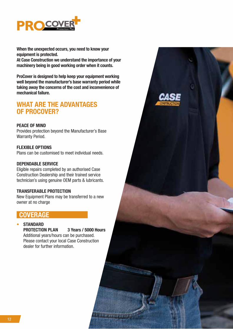
When the unexpected occurs, you need to know your
equipment is protected.
At Case Construction we understand the importance of your
machinery being in good working order when it counts.
ProCover is designed to help keep your equipment working
well beyond the manufacturer’s base warranty period while
taking away the concerns of the cost and inconvenience of
mechanical failure.
WHAT ARE THE ADVANTAGES
OF PROCOVER?
PEACE OF MIND
Provides protection beyond the Manufacturer’s Base
Warranty Period.
FLEXIBLE OPTIONS
Plans can be customised to meet individual needs.
DEPENDABLE SERVICE
Eligible repairs completed by an authorised Case
Construction Dealership and their trained service
technician’s using genuine OEM parts & lubricants.
TRANSFERABLE PROTECTION
New Equipment Plans may be transferred to a new
owner at no charge
COVERAGE
• STANDARD
PROTECTION PLAN 3 Years / 5000 Hours
Additional years/hours can be purchased.
Please contact your local Case Construction
dealer for further information.
134
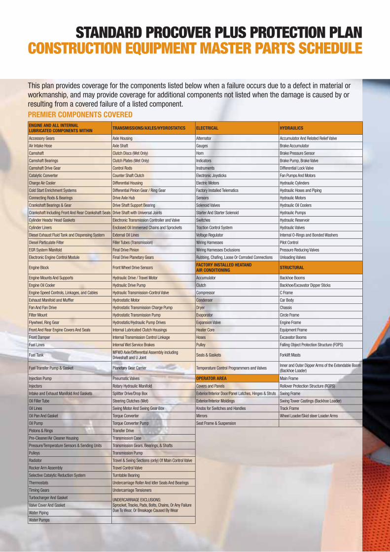
This plan provides coverage for the components listed below when a failure occurs due to a defect in material or
workmanship, and may provide coverage for additional components not listed when the damage is caused by or
resulting from a covered failure of a listed component.
ENGINE AND ALL INTERNAL
LUBRICATED COMPONENTS WITHINTRANSMISSIONS/AXLES/HYDROSTATICS ELECTRICAL HYDRAULICS
Accessory Gears Axle Housing Alternator Accumulator And Related Relief Valve
Air Intake Hose Axle Shaft Gauges Brake Accumulator
Camshaft Clutch Discs (Wet Only) Horn Brake Pressure Sensor
Camshaft Bearings Clutch Plates (Wet Only) Indicators Brake Pump, Brake Valve
Camshaft Drive Gear Control Rods Instruments Differential Lock Valve
Catalytic Converter Counter Shaft Clutch Electronic Joysticks Fan Pumps And Motors
Charge Air Cooler Differential Housing Electric Motors Hydraulic Cylinders
Cold Start Enrichment Systems Differential Pinion Gear / Ring Gear Factory Installed Telematics Hydraulic Hoses and Piping
Connecting Rods & Bearings Drive Axle Hub Sensors Hydraulic Motors
Crankshaft Bearings & Gear Drive Shaft Support Bearing Solenoid Valves Hydraulic Oil Coolers
Crankshaft Including Front And Rear Crankshaft Seals Drive Shaft with Universal Joints Starter And Starter Solenoid Hydraulic Pumps
Cylinder Heads/ Head Gaskets Electronic Transmission Controller and Valve Switches Hydraulic Reservoir
Cylinder Liners Enclosed Oil Immersed Chains and Sprockets Traction Control System Hydraulic Valves
Diesel Exhaust Fluid Tank and Dispensing System External Oil Lines Voltage Regulator Internal O-Rings and Bonded Washers
Diesel Particulate Filter Filler Tubes (Transmission) Wiring Harnesses Pilot Control
EGR System Manifold Final Drive Pinion Wiring Harnesses Exclusions Pressure Reducing Valves
Electronic Engine Control Module Final Drive Planetary Gears Rubbing, Chafi ng, Loose Or Corroded Connections Unloading Valves
Engine Block Front Wheel Drive SensorsFACTORY INSTALLED HEATAND
AIR CONDITIONINGSTRUCTURAL
Engine Mounts And Supports Hydraulic Drive / Travel Motor Accumulator Backhoe Booms
Engine Oil Cooler Hydraulic Drive Pump Clutch Backhoe/Excavator Dipper Sticks
Engine Speed Controls, Linkages, and Cables Hydraulic Transmission-Control Valve Compressor C Frame
Exhaust Manifold and Muffl er Hydrostatic Motor Condenser Car Body
Fan And Fan Drive Hydrostatic Transmission Charge Pump Dryer Chassis
Filter Mount Hydrostatic Transmission Pump Evaporator Circle Frame
Flywheel, Ring Gear Hydrostatic/Hydraulic Pump Drives Expansion Valve Engine Frame
Front And Rear Engine Covers And Seals Internal Lubricated Clutch Housings Heater Core Equipment Frame
Front Damper Internal Transmission Control Linkage Hoses Excavator Booms
Fuel Lines Internal Wet Service Brakes Pulley Falling Object Protection Structure (FOPS)
Fuel TankMFWD Axle/Differential Assembly including
Driveshaft and U JointSeals & Gaskets Forklift Masts
Fuel Transfer Pump & Gasket Planetary Gear Carrier Temperature Control Programmers and ValvesInner and Outer Dipper Arms of the Extendable Boom
(Backhoe Loader)
Injection Pump Pneumatic Valves OPERATOR AREA Main Frame
Injectors Rotary Hydraulic Manifold Covers and Panels Rollover Protection Structure (ROPS)
Intake and Exhaust Manifold And Gaskets Splitter Drive/Drop Box Exterior/Interior Door/Panel Latches, Hinges & Struts Swing Frame
Oil Filler Tube Steering Clutches (Wet) Exterior/Interior Moldings Swing Tower Castings (Backhoe Loader)
Oil Lines Swing Motor And Swing Gear Box Knobs for Switches and Handles Track Frame
Oil Pan And Gasket Torque Converter Mirrors Wheel Loader/Skid steer Loader Arms
Oil Pump Torque Converter Pump Seat Frame & Suspension
Pistons & Rings Transfer Drive
Pre-Cleaner/Air Cleaner Housing Transmission Case
Pressure/Temperature Sensors & Sending Units Transmission Gears, Bearings, & Shafts
Pulleys Transmission Pump
Radiator Travel & Swing Sections (only) Of Main Control Valve
Rocker Arm Assembly Travel Control Valve
Selective Catalytic Reduction System Turntable Bearing
Thermostats Undercarriage Roller And Idler Seals And Bearings
Timing Gears Undercarriage Tensioners
Turbocharger And GasketUNDERCARRIAGE EXCLUSIONS:
Sprocket, Tracks, Pads, Bolts, Chains, Or Any Failure
Due To Wear, Or Breakage Caused By Wear
Valve Cover And Gasket
Water Piping
Water Pumps
STANDARD PROCOVER PLUS PROTECTION PLAN
CONSTRUCTION EQUIPMENT MASTER PARTS SCHEDULE
PREMIER COMPONENTS COVERED

14
CX C-SERIES
HYDRAULIC EXCAVATORS

15

16
ENGINEModel _______________________________________ ISUZU AL-6HK1X
Type __________________Water-cooled, 4-cycle diesel, 6-cylinder in line,
Electronically controlled, high pressure common rail system, variable
geometry turbocharger, air cooled intercooler, triple exhaust gas
recirculation, DPD system with auto-regeneration. Tier 4 interim certifi ed.
Number of cylinders/displacement____________________ 6/7.79l
Bore/Stroke ____________________________________ 115 x 125 mm
Horsepower 80/1269/EEC ___________________ 154 kw @ 1800 min-1
Maximum torque 80/1269/EEC _______________ 900 Nm @ 1500 min-1
HYDRAULIC SYSTEMMax oil fl ow __________________________ 2 x 243 l/min @ 1800 min-1
2 variable displacement axial piston pumps with regulating system
Boom/Arm/Bucket ___________________________________ 37.3 MPa
Swing circuit _______________________________________ 29.4 MPa
Travel ____________________________________________ 34.3 Mpa
SWINGMax upperstructure swing speed __________________________ 10 rpm
TRAVELTravel motor ________________ Variable displacement axial piston motor
Max travel speed ____________ 5.4 km/h (Automatic travel speed shifting)
Low travel speed _____________________________________3.2 km/h
Gradeability ________________________________________70% (35°)
Drawbar pull _________________________________________ 233 kN
ELECTRICAL SYSTEMCircuit __________________________________________ 24 V 5.0 kW
Alternator ___________________________________________50 Amp
UNDERCARRIAGENumber of carriers rollers (each side) ___________________________ 2
Number of track rollers (each side) _____________________________ 9
Number of shoes (each side) ________________________________ 50
Type of shoe ________________________________ Triple grouser shoe
CIRCUIT AND
COMPONENT CAPACITIESFuel tank _____________________________________________ 450 l
Hydraulic system _______________________________________ 300 l
Cooling system ________________________________________ 30.8 l
WEIGHT AND GROUND PRESSURE
With 3.18 m Arm, 1.1 m3 bucket, operator, lubricant, coolant, full fuel tank and top guard OPG level 2
CX300C LC WEIGHT (kg)
600 mm grouser shoe 29.300
CX C-SERIES
HYDRAULIC EXCAVATORS

17
A
B
H
I
E
F
C
D
J
G
K
L
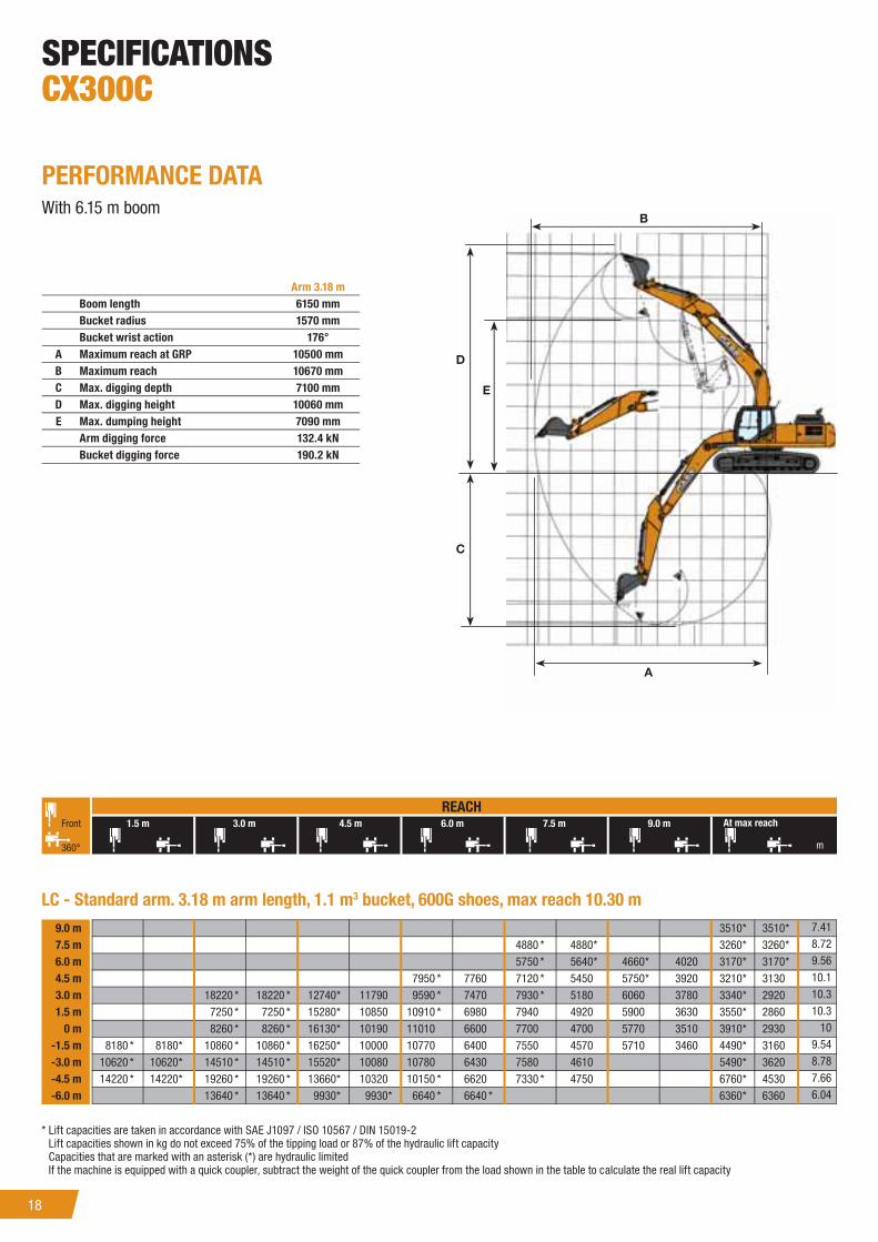
SPECIFICATIONS
CX300C
GENERAL DIMENSIONS
With 6.15 m boom
CX300C LC Arm 3.18 m
Overall length (without attachment) 5580 mm
A Overall length (with attachment) 10450 mm
B Overall height (with attachment) 3260 mm
C Cab height 3080 mm
D Upper structure overall width 2890 mm
E Swing (rear end radius) 3160 mm
F Clearance height under upper structure 1180 mm
G Minimum ground clearance 470 mm
H Wheel base (Center to center of wheels) 3980 mm
I Crawler overall length 4850 mm
L Crawler tracks height 1040 mm
J Track gauge 2600 mm
K Undercarriage overall width (with 600 mm shoes) 3400 mm
18
B
D
C
A
E
PERFORMANCE DATA
With 6.15 m boom
Arm 3.18 m
Boom length 6150 mm
Bucket radius 1570 mm
Bucket wrist action 176°
A Maximum reach at GRP 10500 mm
B Maximum reach 10670 mm
C Max. digging depth 7100 mm
D Max. digging height 10060 mm
E Max. dumping height 7090 mm
Arm digging force 132.4 kN
Bucket digging force 190.2 kN
SPECIFICATIONS
CX300C
m
3510 * 3510 *
4880 * 4880 * 3260 * 3260 *
5750 * 5640 * 4660 * 4020 3170 * 3170 *
7950 * 7760 7120 * 5450 5750 * 3920 3210 * 3130
18220 * 18220 * 12740 * 11790 9590 * 7470 7930 * 5180 6060 3780 3340 * 2920
7250 * 7250 * 15280 * 10850 10910 * 6980 7940 4920 5900 3630 3550 * 2860
8260 * 8260 * 16130 * 10190 11010 6600 7700 4700 5770 3510 3910 * 2930
8180 * 8180 * 10860 * 10860 * 16250 * 10000 10770 6400 7550 4570 5710 3460 4490 * 3160
10620 * 10620 * 14510 * 14510 * 15520 * 10080 10780 6430 7580 4610 5490 * 3620
14220 * 14220 * 19260 * 19260 * 13660 * 10320 10150 * 6620 7330 * 4750 6760 * 4530
13640 * 13640 * 9930 * 9930 * 6640 * 6640 * 6360 * 6360
7.41
8.72
9.56
10.1
10.3
10.3
10
9.54
8.78
7.66
6.04
9.0 m
7.5 m
6.0 m
4.5 m
3.0 m
1.5 m
0 m
-1.5 m
-3.0 m
-4.5 m
-6.0 m
LC - Standard arm. 3.18 m arm length, 1.1 m3 bucket, 600G shoes, max reach 10.30 m
1.5 m 3.0 m 4.5 m 6.0 m 7.5 m 9.0 m
360°
Front
REACH
At max reach
* Lift capacities are taken in accordance with SAE J1097 / ISO 10567 / DIN 15019-2
Lift capacities shown in kg do not exceed 75% of the tipping load or 87% of the hydraulic lift capacity
Capacities that are marked with an asterisk (*) are hydraulic limited
If the machine is equipped with a quick coupler, subtract the weight of the quick coupler from the load shown in the table to calculate the real lift capacity

19
SPECIFICATIONS
CX350C
ENGINEModel _______________________________________ ISUZU AL-6HK1X
Type __________________Water-cooled, 4-cycle diesel, 6-cylinder in line,
Electronically controlled, high pressure common rail system, variable
geometry turbocharger, air cooled intercooler, triple exhaust gas
recirculation, DPD system with auto-regeneration. Tier 4 interim certifi ed.
Number of cylinders/displacement _________________________ 6/7.79l
Bore/Stroke ____________________________________ 115 x 125 mm
Horsepower 80/1269/EEC ___________________ 198 kw @ 1900 min-1
Maximum torque 80/1269/EEC ______________ 1043 Nm @ 1500 min-1
HYDRAULIC SYSTEMMax oil fl ow __________________________ 2 x 285 l/min @ 1900 min-1
2 variable displacement axial piston pumps with regulating system
Boom/Arm/Bucket ___________________________________ 37.3 MPa
Swing circuit _______________________________________ 30.4 MPa
Travel ____________________________________________ 34.3 Mpa
SWINGMax upperstructure swing speed _________________________ 9.7 rpm
Travel
Travel motor ________________ Variable displacement axial piston motor
Max travel speed ____________ 5.4 km/h (Automatic travel speed shifting)
Low travel speed _____________________________________3.2 km/h
Gradeability ________________________________________70% (35°)
Drawbar pull _________________________________________ 264 kN
ELECTRICAL SYSTEMCircuit ________________________________________________ 24V
Alternator ___________________________________________50 Amp
UNDERCARRIAGENumber of carriers rollers (each side) ___________________________ 2
Number of track rollers (each side) _____________________________ 8
Number of shoes (each side) ________________________________ 48
Type of shoe ________________________________ Triple grouser shoe
CIRCUIT AND
COMPONENT CAPACITIESFuel tank _____________________________________________ 580 l
Hydraulic system _______________________________________ 350 l
Cooling system ________________________________________ 35.4 l
WEIGHT AND GROUND PRESSURE
With 3.25 m arm, 1.4 m3 bucket, operator, lubricant, coolant, full fuel tank and top guard OPG level 2
CX350C LC WEIGHT (kg)
600 mm grouser shoe 35.600

20
A
B
H
I
E
F
C
D
J
G
K
L
CX C-SERIES
HYDRAULIC EXCAVATORS
GENERAL DIMENSIONS
With 6.45 m boom
CX350C LC Arm 3.25 m
Overall length (without attachment) 6010 mm
A Overall length (with attachment) 11140 mm
B Overall height (with attachment) 3420 mm
C Cab height 3130 mm
D Upper structure overall width 3030 mm
E Swing (rear end radius) 3550 mm
F Clearance height under upper structure 1210 mm
G Minimum ground clearance 480 mm
H Wheel base (Center to center of wheels) 4040 mm
I Crawler overall length 4980 mm
L Crawler tracks height 1090 mm
J Track gauge 2600 mm
K Undercarriage overall width (with 600 mm shoes) 3200 mm

21
B
D
C
A
E
SPECIFICATIONS
CX350C
PERFORMANCE DATA
With 6.45 m boom
LIFTING CAPACITY
CX350C LC Arm 3.25 m
Boom length 6450 mm
Bucket radius 1680 mm
Bucket wrist action 173°
A Maximum reach at GRP 10980 mm
B Maximum reach 11170 mm
C Max. digging depth 7340 mm
D Max. digging height 10370 mm
E Max. dumping height 7230 mm
Arm digging force 178.0 kN
Bucket digging force 248.0 kN
m
3780 * 3780 *
6520 * 6520 * 5130 * 5130 * 3540 * 3540 *
7150 * 7030 * 6470 * 5110 3460 * 3460 *
7090 * 7090 * 9400 * 9400 * 7930 * 6870 7020 * 4930 3830 * 3580 3500 * 3500 *
17960 * 17960 * 15390 * 14530 11120 * 9350 8940 * 6470 7550 4700 5240 * 3490 3620 * 3320
7410 * 7410 * 17550 * 13450 12530 * 8670 9760 * 6090 7370 4480 5380 * 3380 3850 * 3260
10430 * 10430 * 18360 * 12670 13280 * 8180 9620 5800 7180 4310 4250 * 3350
10410 * 10410 * 14220 * 14220 * 18300 * 12540 13300 * 7970 9450 5640 7100 4240 4860 * 3640
14430 * 14430 * 19090 * 19090 * 17390 * 12690 12860 * 8030 9470 5700 7170 4340 5910 * 4200
19110 * 19110 * 21450 * 21450 * 15310 * 13040 11430 * 8290 8410 * 6020 7020 * 5270
15410 * 15410 * 11340 * 11340 * 7940 * 7940 * 6700 * 6700 *
REACH
1.5 m 3.0 m 4.5 m 6.0 m 7.5 m 9.0 m 10.5 m
360°
Front At max reach
8.23
9.36
10.1
10.6
10.7
10.7
10.4
9.91
9.13
8.01
6.4
9.0 m
7.5 m
6.0 m
4.5 m
3.0 m
1.5 m
0 m
-1.5 m
-3.0 m
-4.5 m
-6.0 m
LC - Standard arm. 3.25 arm length, 1.4 m3 bucket, 600G shoes, max reach 10.70 m
* Lift capacities are taken in accordance with SAE J1097 / ISO 10567 / DIN 15019-2
Lift capacities shown in kg do not exceed 75% of the tipping load or 87% of the hydraulic lift capacity
Capacities that are marked with an asterisk (*) are hydraulic limited
If the machine is equipped with a quick coupler, subtract the weight of the quick coupler from the load shown in the table to calculate the real lift capacity

22
CX C-SERIES
HYDRAULIC EXCAVATORS
ENGINEModel ______________________ Tier 4 interim certifi ed ISUZU AL-6UZ1X
Type __________________Water-cooled, 4-cycle diesel, 6-cylinder in line,
High pressure common rail system (electric control), turbocharger with air
cooled intercooler, without cooling fan, DPD system
Number of cylinders ________________________________________ 6
Bore/Stroke ____________________________________ 120 x 145 mm
Horsepower 80/1269/EEC ___________________ 270 kW @ 2000 min-1
(without fan-pump)
Horsepower 80/1269/EEC ___________________ 245 kW @ 2000 min-1
(with fan-pump)
Maximum torque 80/1269/EEC ______________ 1435 Nm @ 1500 min-1
(without fan-pump)
HYDRAULIC SYSTEMMax oil fl ow __________________________ 2 x 364 l/min @ 2000 min-1
2 variable displacement axial piston pumps with regulating system
Working circuit pressure
Boom/Arm/Bucket ___________________________________ 31.4 MPa
Boom/Arm/Bucket (with auto power up) ___________________ 34.3 MPa
Swing circuit _______________________________________ 29.4 MPa
Travel ____________________________________________ 34.3 Mpa
SWINGMaximum swing speed ________________________________ 9 min-1
TRAVELTravel motor ________________ Variable displacement axial piston motor
Max travel speed ____________ 5.3 km/h (Automatic travel speed shifting)
Low travel speed _____________________________________3.2 km/h
Gradeability ________________________________________70% (35°)
Drawbar pull _________________________________________ 340 kN
ELECTRICAL SYSTEMBattery ______________________________________________2x12V
Alternator ___________________________________________50 Amp
UNDERCARRIAGENumber of carriers rollers (each side) ___________________________ 2
_________________________________(Fixed sideframe undercarriage)
Number of carriers rollers (each side) ___________________________ 3
____________________________ (Retractable sideframe undercarriage)
Number of track rollers (each side) _____________________________ 9
Number of shoes (each side) ________________________________ 50
Type of shoe ________________________________ Triple grouser shoe
CAPACITIESFuel tank _____________________________________________ 650 l
Hydraulic system _______________________________________ 460 l
Cooling system _________________________________________ 47 l
WEIGHT
With 3.38 m arm, 2.0 m3 HD bucket.
CX470C LC WEIGHT (kg)*
600 mm grouser shoe
with fi xed sideframe undercarriage46.900
* With operator, lubricant, coolant and full fuel tank

2323
A
F
E
D
J
G
C
M
H
K
L
I
B
SPECIFICATIONS
C470C
GENERAL DIMENSIONS
CX470C LC Arm 3.38 m
Overall length (without attachment) 6445 mm
A Overall length (with attachment) 12060 mm
B Overall height (with attachment) 3620 mm
C Cab height (Top of head guard) 3440 mm
D Upper structure overall width (without catwalks) 3060 mm
E Upper structure overall width (with catwalks) 3590 mm
F Swing (rear end) radius 3730 mm
G Clearance height under upper structure 1330 mm
H Minimum ground clearance 540 mm
I Wheel base (Center to center of wheels) 4400 mm
J Crawler overall length 5450 mm
K Track gauge 2750 mm
L Undercarriage overall width (with 600 mm shoes) 3350 mm
M Crawler tracks height 1240 mm

24
D
C
E
B
A
CX470C
SPECIFICATIONS
CX470C
PERFORMANCE DATA
CX470C LC Arm 3.38 m
Boom length 6980 mm
Bucket radius 1840 mm
Bucket wrist action 176°
A Maximum reach at GRP 11770 mm
B Maximum reach 12000 mm
C Max. digging depth 7720 mm
D Max. digging height 11140 mm
E Max. dumping height 7740 mm
DIGGING FORCE
With 2.0 m3 HD bucket (ISO 6015)
Arm 3.38 m
Arm digging force 209 kN
- with auto power boost 229 kN
Bucket digging force 247 kN
- with auto power boost 270 kN
25
A
F
E
D
J
G
C
M
H
K
L
I
B
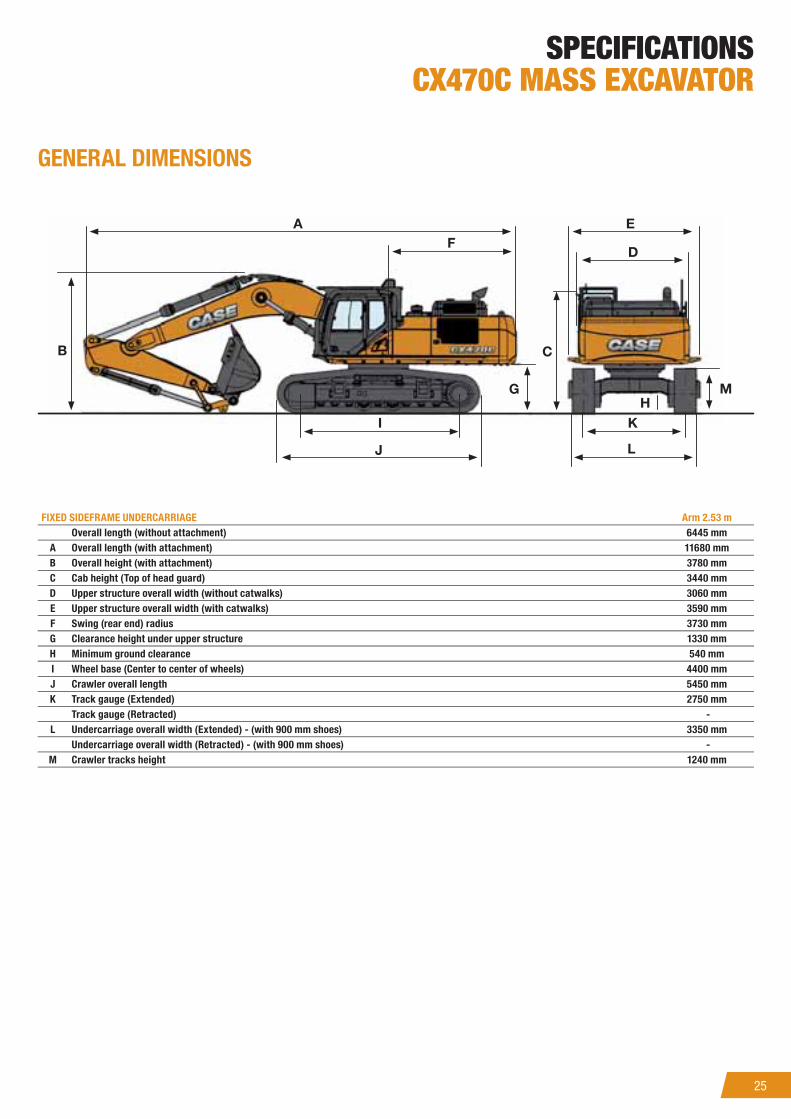
SPECIFICATIONS
CX470C MASS EXCAVATOR
GENERAL DIMENSIONS
FIXED SIDEFRAME UNDERCARRIAGE Arm 2.53 m
Overall length (without attachment) 6445 mm
A Overall length (with attachment) 11680 mm
B Overall height (with attachment) 3780 mm
C Cab height (Top of head guard) 3440 mm
D Upper structure overall width (without catwalks) 3060 mm
E Upper structure overall width (with catwalks) 3590 mm
F Swing (rear end) radius 3730 mm
G Clearance height under upper structure 1330 mm
H Minimum ground clearance 540 mm
I Wheel base (Center to center of wheels) 4400 mm
J Crawler overall length 5450 mm
K Track gauge (Extended) 2750 mm
Track gauge (Retracted) -
L Undercarriage overall width (Extended) - (with 900 mm shoes) 3350 mm
Undercarriage overall width (Retracted) - (with 900 mm shoes) -
M Crawler tracks height 1240 mm

26
D
C
E
B
A
SPECIFICATIONS
CX470C MASS EXCAVATOR
PERFORMANCE DATA
FIXED SIDEFRAME UNDERCARRIAGE Arm 2.53 m
Boom length 6550 mm
Bucket radius 1850 mm
Bucket wrist action 161 °
A Maximum reach at GRP 10560 mm
B Maximum reach 10810 mm
C Max. digging depth 6490 mm
D Max. digging height 10520 mm
E Max. dumping height 7180 mm
DIGGING FORCE
With 3.0 m3 HD bucket (ISO 6015)
Arm 3.53 m
Arm digging force 255 kN
- with auto power boost 279 kN
Bucket digging force 286 kN
- with auto power boost 313 kN
27
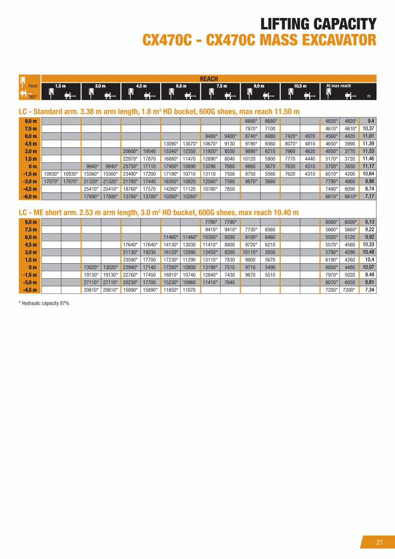
LIFTING CAPACITY
CX470C - CX470C MASS EXCAVATOR
m
REACH
360°
6680 * 6680 * 4820 * 4820 *
7970 * 7100 4610 * 4610 *
9480 * 9400 * 8740 * 6880 7420 * 4970 4560 * 4420
13090 * 13070 * 10670 * 9130 9190 * 6560 8070 * 4810 4650 * 3990
20600 * 19540 15340 * 12350 11920 * 8550 9890 * 6210 7960 4620 4850 * 3770
22970 * 17870 16880 * 11470 12890 * 8040 10120 5900 7770 4440 5170 * 3720
9940 * 9940 * 23750 * 17110 17400 * 10890 13290 7660 9860 5670 7630 4310 5700 * 3850
10930 * 10930 * 15560 * 15560 * 23490 * 17200 17190 * 10710 13110 7500 9750 5560 7620 4310 6510 * 4200
17070 * 17070 * 21320 * 21320 * 21780 * 17440 16300 * 10820 12560 * 7560 9670 * 5660 7790 * 4860
25410 * 25410 * 18760 * 17570 14260 * 11120 10780 * 7850 7490 * 6090
17890 * 17890 * 13780 * 13780 * 10260 * 10260 * 6610 * 6610 *
7790 * 7790 * 6000 * 6000 *
9410 * 9410 * 7730 * 6560 5660 * 5660 *
11460 * 11460 * 10350 * 9280 9100 * 6460 5520 * 5120
17640 * 17640 * 14130 * 13030 11410 * 8800 9720 * 6210 5570 * 4560
21130 * 19230 16120 * 12090 12450 * 8280 10110 * 5930 5790 * 4290
23590 * 17700 17230 * 11290 13110 * 7830 9900 5670 6190 * 4260
13020 * 13020 * 23940 * 17140 17280 * 10800 13190 * 7510 9710 5490 6850 * 4480
19130 * 19130 * 22760 * 17450 16810 * 10740 12840 * 7430 9670 5510 7970 * 5020
27110 * 27110 * 20230 * 17700 15230 * 10960 11410 * 7640 8070 * 6050
20610 * 20610 * 15890 * 15890 * 11850 * 11070 7200 * 7200*
REACH
* Hydraulic capacity 87%
1.5 m 3.0 m 4.5 m 6.0 m 7.5 m 9.0 m 10.5 m At max reach
LC - Standard arm. 3.38 m arm length, 1.8 m3 HD bucket, 600G shoes, max reach 11.50 m
LC - ME short arm. 2.53 m arm length, 3.0 m3 HD bucket, 600G shoes, max reach 10.40 m
9.0 m
7.5 m
6.0 m
4.5 m
3.0 m
1.5 m
0 m
-1.5 m
-3.0 m
-4.5 m
-6.0 m
9.0 m
7.5 m
6.0 m
4.5 m
3.0 m
1.5 m
0 m
-1.5 m
-3.0 m
-4.5 m
9.4
10.37
11.01
11.39
11.53
11.46
11.17
10.64
9.86
8.74
7.17
8.13
9.22
9.92
10.33
10.48
10.4
10.07
9.49
8.61
7.34
Front 1,5 m 3,0 m 4,5 m 6,0 m 7,5 m 9,0 m 10,5 m
9,0 m
7,5 m
6,0 m
4,5 m
3,0 m
1,5 m
0 m
-1,5 m
-3,0 m
-4,5 m
-6,0 m
9,0 m
7,5 m
6,0 m
4,5 m
3,0 m
1,5 m
0 m
-1,5 m
-3,0 m
-4,5 m
9,4
10,37
11,01
11,39
11,53
11,46
11,17
10,64
9,86
8,74
7,17
8,13
9,22
9,92
10,33
10,48
10,4
10,07
9.49
8,61
7,34

EXPERTS FOR THE REAL WORLD
SINCE 1842
www.casece.com
CustomerCCACCssistanc
CustomestoCAAC
ecc
1300 99 CASE
NOTE: CASE provides specifi c outfi ts for various countries and many
optional fi ttings (OPT). The illustrations on this or other leafl ets may
relate to standard or optional fi ttings. Please consult your CASE
dealer for any information in this regard and any possible updating
on components. CNH Industrial reserves the right to modify machine
specifi cations without incurring any obligation relating to such changes.
CASE CONSTRUCTION EQUIPMENT
CONTACT INFORMATION
AUSTRALIA
31-53 Kurrajong Road
St. Marys nsw 2760
Form No. ANZ3305CCGB - Printed in Australia - MediaCross Firenze - 06/15