Embed Size (px)
Citation preview

Technology software modulefor the
with
SIMOREG DC - MASTER 6RA70 and T300or
SIMOVERT MASTER DRIVES CUVC and T300
Implementation and owner: Industrial Solutions and ServicesInformation TechnologyPlant SolutionI&S IT PS Erl 35
Sales/marketing: Automation & Drives A & D MC
AL: NECCN: NStatistical product number: 49019900
closed-loop control of crane drives
Introduction and overview

Notes/FAQ´s (frequently Asked Questions):
• T300 with SIMOREG DC MASTER 6RA70Current values of DC drives (SIMOREG DC MASTER 6RA70) are referred to the devicecurrent. In opposition to the DC drives, the current values of AC drives (SIMOVERTMASTERDRIVES CUVC) are referred to the motor current.With SIMOREG DC MASTER 6RA70 100% is not equivalent to the motor current, but tothe device current of the SIMOREG DC MASTER 6RA70.
With load-dependent field weakening you must pay attention to the input of outputhyperbole characteristic (P527-P538). The output hyperbole characteristic must be eithernormalised to the device current or the current of the SIMOREG DC MASTER 6RA70 (tothe T300/pcd 4) must be scaled to the motor current. (module hoisting gear)
• Closed-loop position controlWhen automatic mode is selected, the maximum speed setpoint (+/-100%) isautomatically entered (with the correct sign), dependent on the difference between theactual position and the position setpoint.
When semi-automatic mode is selected, the master switch enters the maximum speedsetpoint. Depending on the speed setpoint polarity the position setpoint 1 or positionsetpoint 2 is selected.A positive speed setpoint needs a position setpoint1, which is larger than the actualposition, to approach the target position.A negative speed setpoint needs a position setpoint2, which is smaller than the actualposition, to approach the target position.(module hoisting gear, holding gear, slewing gear and traversing gear)

s
Introduction and overview V1.20 2 01.01.2001Copyright © Siemens AG All Rights Reserved
Changes
Version Date ChangesV1.10 01.07.99V1.11 01.11.99 - Type transformation of parameter (H171-H174): Nominal pulse
number for 100 % position (H171, H173 transformed; H172, H174deleted)
V1.20 01.01.01 - Parameter for factory setting added- Max. process data of the communication board have been in-
creased to 16 process data words- „free“ process data has been connected with the basic drive /
communication board- Allocation of digital inputs and digital outputs has been changed for
commissioning purposes- Allocation of the alarm display has been changed

s
Introduction and overview V1.20 3 01.01.2001Copyright © Siemens AG All Rights Reserved
NOTES
This documentation describes the software implementation of the closed-loop technology controlof crane drives.
The installation, connection and commissioning of the equipment and modules is not describedhere. These are provided in sufficient detail in the Instruction Manual of the equipment.
The information on danger, warning notes and cautionary measures should also be taken fromthe appropriate Instruction Manuals of the devices.
Further, it is assumed that the equipment is installed, commissioned and serviced by suitablytrained and qualified personnel, who are both knowledgeable about the product itself as well asthe particular industry sector.
This document also doesn't describe basic and simpler functions related with crane drives.
No part of this publication may be reproduced or transmitted in any form or by any means, elec-tronic or mechanical, including photocopy, recording, or any information storage and retrievalsystem, without permission in writing from the publisher.

s
Introduction and overview V1.20 4 01.01.2001Copyright © Siemens AG All Rights Reserved
STRUCTURE
1 Description of the concept.......................................................................... 5
1.1 General overview...................................................................................................................... 5
1.2 Hardware and Software components of the T300 technology module..................................... 8
1.3 Overview of the various drives, modules and functions ........................................................ 10
1.4 Communications between SIMATIC and drive units .............................................................. 12
1.5 Communications within the drive units ................................................................................... 14
1.6 Communications between 2 drive units.................................................................................. 14
1.7 Overview of communications..................................................................................................15
1.8 Basic signal characteristics and structure of the closed-loop control ..................................... 16
1.9 Connecting-up diagram for the T300...................................................................................... 17
1.10 Necessary basic device parameters....................................................................................... 18
1.10.1 SIMVOVERT MASTER DRIVE CUVC .............................................................................. 181.10.2 SIMOREG DC MASTER 6RA70 ....................................................................................... 20

s
Introduction and overview V1.20 5 01.01.2001Copyright © Siemens AG All Rights Reserved
1 Description of the concept
1.1 General overview
Presently, SIMOREG DC-MASTER 6RA70 devices are being used for the closed-loop control of DCcrane drives and SIMOVERT MASTER DRIVES CUVC for AC drives.
In order to implement the technological closed-loop control tasks and functions, in almost all cases, it isnecessary to use an additional T300 technology processor in the units mentioned above.
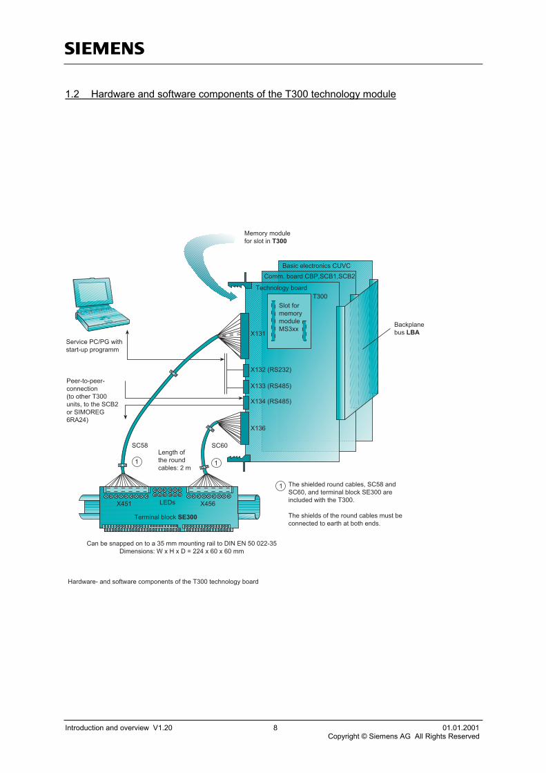
The T300 is a freely-configurable technology processor with analog and digital inputs and outputs, twoconnections for pulse encoders, serial interfaces etc. On the plant/system side, these connections arerouted to the SE300 terminal block. This is connected to the T300 technology module using screenedround cables. (For this application, only the pulse encoder connections, the analog inputs and outputsand the serial interfaces are used. The digital inputs and outputs are only used for commissioning pur-poses.)
The sub-modules (Eproms, program memory modules) for the T300 are programmed with the STRUCprogramming language from SIMADYN D. However, these are not required for this particular applica-tion.
The T300 technology module is used in the electronics box of the drive converter units as option board(slot 2). Module T300 is shown on Page 9, the installation on Page 8 as well as a connection exampleon page 16.
For the various crane drive types, the necessary and frequently required closed-loop control structuresand functions required for these drives, are combined in drive-specific software modules. These arelisted in the table on Page 10 together with the functions which have been implemented.
If other functions are required, which are not listed in the table on the next page, then these must beimplemented as custom software.
With the software, the open-loop- and closed-loop control tasks are clearly separated. These are exe-cuted in the systems which have been designed for these purposes, i.e. the implementation of all of theopen-loop control functions in the SIMATIC as well as implementation of all closed-loop control func-tions which are distributed in the drive control system.
Digital interlocking, e.g. controlling contactors, generating enable signals for the drive must thereforebe implemented in the higher-level open-loop control system. Only the drive-specific closed-loop con-trol circuits and functions are implemented in the freely-programmable technology modules.
The closed-loop technology control is realized in the technology modules. However, the closed-loopspeed control and the closed-loop current control in the basic drives are fully utilized.

s
Introduction and overview V1.20 6 01.01.2001Copyright © Siemens AG All Rights Reserved
The drive units communication with the SIMATIC via Profibus SINEC L2 DP with PPO type 5 (4 PKWand 10 PZD words). (Alternative a free configuration of the cyclical data (no PPO type) with the Engi-neering tool DriveES is possible, when a communication board CBP2 is used. There are up to 16 pro-cess data words configurable. A parameter area (PKW) is configurable, .independent on the amount ofprocess data. However the allocation of the process data (Chapter 3) has to be noticed while usage.
The complete control (control words and setpoint-actual values) of the drive converters is realized viathis interface. (The communication board CBP/CBP2 has to be inserted in slot G via the adaptionboard ADB (slot 3)).
The essential signals from the automation system to the drives are four 16-bit control words as well asthe setpoints for the speeds and the position setpoint for a closed-loop position control.
The communications between the technology module and a basic drive is realized through a DPR (dualport Ram).
The setpoint is entered from the master switch via ET200, SIMATIC and Profibus to the drive unit.
The position actual values must be sensed for the closed-loop position control of a drive. In manycases, this can be realized using the speed encoder is mounted on the motor.
For the grab position control of a grab crane or for the closed-loop synchronous control of two drives, itis necessary to sense the position actual values of both drives. This can also be realized using thepulse encoder, mounted on the motor for the speed actual values.
The pulse encoder signals for the speed actual value sensing are fed to the basic drives and for theposition actual value sensing, to the technology module. It is also possible to mount additional pulseencoders on the cable drum.
The necessary parameters are defined as technology parameters and these can be set and changed.They are set via the basic drive operator panel. It is also possible to parameterize the units (basic driveand technology module) using the SIMOVIS service tool. (The database of the T300 technology mod-ule is included in delivery.)
An overview of the concept is shown in the following block diagram using as an example, the holding-and closing gear of a grab crane. The block diagram is also valid for an individual drive or a master-slave drive.

1
01.01.01 overview concept page 7I&S IT PS Erl 35 V 1.22 3 4 5 6 7 8
ET
S5/7
cable drumHW MT
CB
TB
GG
T
ET ET
cable drumHW MT
CB
TB
GG
T
peer to peern*, i*
master switchHW and SW
n**s*
n*
control wordsstatus words
ET: electrical terminal blockT: pulse encoderHW: holding gearSW: closing gearCB: communication boardTB: technology boardGG: basic unit
s
Introduction and overview V1.20 8 01.01.2001Copyright © Siemens AG All Rights Reserved
1.2 Hardware and software components of the T300 technology module
����
�����������
����������
���������
���
����
�� �����
��� ���� ��
� �
�
��������������������
����!���"#��$������%��������
���&����'�(')�*�%+�%��%,#-�-��.����
'���,%�,-���,������%����%���%+�������#��%�/�%��%+����0�����1 2��) �3�
���.%+��$%+����#�"������4����
���%�$�������!��"#�� ��55
0���-�����#����
�+���+���"�"���#�"�������/��������"�� �/���"�%���������������������������#"�"�*�%+�%+������6
�+���+���"���$�%+����#�"���������#�%���������%�"�%�����%+��%���%+���"�6
����������--�"����%������������#�%��.������%���17��7�������,������������4�8�5�9�5���:����5� ��5� ����
���+����.!�����"
����6�����"��0'/��0�/��0�
0���������%��������;<�
9��"*���,���"���$%*�������-����%���$�%+�������%��+����.!�����"

s
Introduction and overview V1.20 9 01.01.2001Copyright © Siemens AG All Rights Reserved
T300 module with memory module

s
Introduction and overview V1.20 10 01.01.2001Copyright © Siemens AG All Rights Reserved
1.3 Overview of the various drives, modules and functions
Hoisting gear►Load-depending field weakening►Heavy load operation (reduced setpoint)►Jogging►Ramp-function generator changeover for field- weakening and heavy loads►Changeover to synchronous operation control with one-only (manual) setting of the position difference (slave operation)
►Position sensing with synchronization (of the position)
►Closed-loop position control (for automatic- or manual operation)►Non-linear master switch setpoint►Pre-limit switch►Start pulse►Monitoring functions►Current distribution monitoring►Braking with constant distance
Holding gear►Constant field weakening (efficiency)►Heavy load operation (reduced setpoint)►Closed-loop position control (for automation- or manual operation)►Jogging►Ramp-function generator changeover for heavy loads
►Slack rope control►Position sensing with synchronization (of the position)
►Non-linear master switch setpoint►Pre-limit switch►Start pulse►Monitoring functions
Closing gear►Grab adjustment►Start pulse►Current equalization control with polyp grab operation►Changeover to synchronous operation control with one-only (manual) setting of the position difference (slave operation))
►Grab position sensing►Closed-loop grab position control►Jogging►Monitoring functions
Slewing gear►Non-linear master switch setpoint►Closed-loop position control (for automatic or manual operation)►Jogging►Working angle-dependent accelerating time►Working angle-dependent slewing speed
►Position sensing with synchronization (of the position)
►Pre-limit switch►Monitoring functions► Influencing the ramp-function generator dependent on the system deviation
Traversing gear, master►Non-linear master switch setpoint►Closed-loop position control (for automation- or manual operation)►Jogging►Changeover to synchronous operation control with one-only (manual) setting of the position difference (slave operation)
►Position sensing with synchronization (of the position)
►Pre-limit switch►Monitoring functions►Current distribution monitoring
Traversing gear, slave►Current distribution monitoring►Closed-loop synchronous operation control with offset as position difference
►Jogging►Position sensing with synchronization (of the position)
►Monitoring functions

s
Introduction and overview V1.20 11 01.01.2001Copyright © Siemens AG All Rights Reserved
Monitoring functions: Closed-loop control monitoringSpeed actual-actual monitoringOverspeed monitoringZero speed signal
s
Introduction and overview V1.20 12 01.01.2001Copyright © Siemens AG All Rights Reserved
1.4 Communications between SIMATIC and the drive units
The communications between these two systems is implemented via Profibus SINEC L2-DP.This serial peripheral SINEC L2-DP bus system is optimized for extremely fast cyclic master-slaveoperation. In this case, the drives are always operated as slaves; the higher-level system has themaster function, which in this case is the SIMATIC.
The CBP/CBP2 module is used as communication module in the drive units.
The net data structure with which a DP master can access the drives is described in the following text.The SINEC L2-DP transfers the net data with the SRD utility (Send and Request with Data). Thismeans, that net data are always transferred via the bus, both from the master to the slave as well as inreturn telegrams from the slave to the master.
The master formulates a task, the slave processes this task and formulates the appropriate response.There is precisely one task in each telegram from the master to the slave; there is precisely one re-sponse in each telegram from the slave to the master.
The length and structure of the net data are permanently specified, and are known as Parameter Proc-ess data Objects (PPO).
Five types are defined to transfer net data (PPO), with which process data, i.e. control words, statuswords, setpoints and actual values can be simultaneously transferred, also parameters from the mas-ter to the slave and vice versa.
In the following application, only PPO type 5 is used.1
The PPOs are sub-divided into two areas: PKW (parameter identification value)PZD (process data)
The PKW area allows parameter values to be read and written into and parameter descriptions andtexts read. Every drive parameter can be visualized or changed via this mechanism.
The PZD area contains all of the necessary signals which are required for process control. These in-clude control words and setpoints from the automation to the drive and status words and actual valuesfrom the drive to the automation system.
Both areas together result in the net data block (PPO).
The advantage in this case is that in a telegram, both the cyclically required process data can betransferred, and it is also possible to simultaneously access parameters (reading/writing).
1 Cyclical data can be freely-configured by using the communication board CBP2 with the EngineeringTool DriveES (no PPO-type). There are up to 16 process data words configurable. Independent fromthe amount of process data a parameter area (PKW) is configurable. So you are not dependent on the5 predetermined PPO types.

s
Introduction and overview V1.20 13 01.01.2001Copyright © Siemens AG All Rights Reserved
=�5��.�����*
�����.����
�����!����*�������"
>,-�����#����%�������
=�5��.�����*
�!�%���������%��
�0'�����#����%���������"
PPO1
PPO2
PPO3
PPO4
PPO5
PKW PZD
IND PWEPZD1STW1ZSW1
PZD2HSWHIW
PZD3 PZD4 PZD5 PZD6 PZD7 PZD8 PZD9 PZD10
1st 3rd2nd 4th 1st 2nd 3rd 4th 5th 6th 7th 8th 9th 10th
PWE:PZD:PKE:IND:PWE:
Parameter ID valueProcess dataParameter IDIndexParameter value
STW:ZSW:HSW:HIW:
Control word 1Status word 1Main setpointMain actual value
Net-data structure in the "PROFIBUS Profile for PROFIDRIVE Variable-Speed Drives"

s
Introduction and overview V1.20 14 01.01.2001Copyright © Siemens AG All Rights Reserved
1.5 Communications within the drive units
The data transfer within the "slave modules", i.e. between the drive converter and CB, is realized usinginternal SIEMENS data transfer mechanisms, the so-called device response. The data is transferredbetween the communications module and drive converter via the DUAL PORT RAM (DPR).
Data transfer between the communications module CB and the basic drive is realized via a dual portRAM coupling (DPR). Both sides, CB and basic drive can access the memory of the dual port RAMwriting and reading. The dual port RAM chip is provided on the CB.
If an additional TB technology module is provided, then this is switched between the CB and the basicdrive. In this case, the dual port RAM of the CB is the interface to the TB and dual port RAM on the TBis the interface to the basic drive (configuration TB-CB basic drive).
The initialization data transferred between CB and the basic drive is not influenced by the TB, i.e. thetechnology module copies the data from its dual port RAM one-to-one into the dual port RAM of the CBand vice versa. The function must be appropriately configured in the TB.
16 pieces of process data can be transferred in both directions between the TB and basic drive.
1.6 Communications between two drive units
This communications connection is generally used for master-slave drives, where the master setpointfor the slave drive(s) is (are) entered from the master drive.
This is also the case for holding- and closing gears of a grab crane where the speed setpoint for theclosing gear and the current setpoint for the current equalization control is transferred to the closinggear via this coupling.
This coupling is realized using a fast peer-to-peer connection between the technology modules.
A maximum of 5 PZD data words can be transferred in both directions via this interface.

1
01.01.01 1.7 overview of communications I&S IT PS Erl 35 V 1.22 3 4 5 6 7 8
page 15
S7 CBP T300 CU
T300
unit 1
unit 25words
4.wordPWE
3.wordPWE
2.wordIND
1.wordPKE
peerto
peer
PZD 16 words
converter response
PZD max. 16 words
PROFIBUS
PKW
PROFIBUS
PKW
PROFIBUS
PKW
converter response
PKW
converter response
converter response
converter response
converter response

1
01.01.01 1.8 basic signal characteristics and structure of the closed-loop control I&S IT PS Erl 35 V 1.22 3 4 5 6 7 8
technologicalcontrol
n-controller
functions functions
monitoringacknowledge monitoring
acknowledge
control word 2
control word 1
control word technology 1
control word technology 2
setpoints
status word 1
status word 2
status word technology
sist
nist
∆n
i*
M
ML
IG
SIMATIC
ET200 ET200
PROFIBUS
SINEC L2 DP
1
1
2
2
i-controller
T
T300 basic unit
i*
n*n*
nist
nist
nist
page 16
RFG

s
Introduction and overview V1.20 17 01.01.2001Copyright © Siemens AG All Rights Reserved
1.9 Connecting-up diagram for the T300
�
������
���
��
��
���
� ���
��
�����
��� ��� ��� �� ��� �� ��� ��� ��� ���� ��
�����
� ���
���� ����
��
��
��
��
��
��
��
��
��
��
��
��
��
��
��
���
���
���
���
��
���
���
��
���
���
���
���
���
��
� ���
����
��
���
���
���
���
��
������
������
������
������
������
������
��������
� ���
�
���
���
���
��
���
���
���
���
��
���
�� ����
����
�� ����
���
� ���
������
��
���
���
���
���
��
���
����
��
��
��
��
�����������
� �
� �
�
� �
� �
��
���
��
��
�
�
��
����
�
�
�
��
��
��
�
��
�����
�����
���
���
���
�� �
���
���
���
���
����
�� !"#$%!
&'()%!"#$%!
*#$%!�! +',!),!�!+��' ��
������-
�( ($'.�� "#�%
��//!)! ��($�� "#�%������%���%�.
���� ()0�� "#�%
�����&1� "#��+#))! ���2���0"�+($3
���� ()0�� "#�%
�����&1� "#��+#))! ���2���0"�+($3
&'22# �+(��' %�'(),4�!�.�&�*4��&��')��&�
�!)2� ($%���4���5�&' !+���'��!)2� ($��$'+-��6�����!)2� ($%���� 4�����4�����5�&' !+���'��7!������
�#($�"')����8
�#($�"')����8
8���6���9�6��(%�+�# ��
1&:�&��'(),3
���� ()0�'#�"#�%
�����&���2(�������2��(%!�$'(,����2��/')!��!) ($�* ��� /!!,�;7�+7+( �($%'�+'2!�/)'2�7!��(%�+�# ��
�!)�($�� �!)/(+!� 1"!!)��'�"!!)3
������%���%�. ������������2��
6��7!)��� � �')������� �!)/(+!�#%!(�$!<
�!)�($�� �!)/(+!��!�.��/')�%!)=�+!4%�()��#"�;��7�*&�*>
��( ($'.�'#�"#�%
?���%�. ($�$!=!$4�2(��9 "#��/)!@#! +0�����-?A9 "#��+#))! ��"!)�+7( !$5��2�
�"#$%!�! +',!)�� "#�%
�����4� �;�)!
�����4���;�)!
8�+)'�")'+!%%')&*:5
��&��� ��8?A
�$'��/')2!2')0
2',#$!4�!�.�8�����
�!)'�"#$%!
�!)'�"#$%!
���B�%�.
*#$%!�! +',!),!�!+��' �
������!+7 '$'.0��'(),�+' !+��' �,�(.)(2

s
Introduction and overview V1.20 18 01.01.2001Copyright © Siemens AG All Rights Reserved
1.10 Basic drive converter parameters required
In order to establish error-free communications and functionality between SIMATIC and the drive unit,the following parameter settings must be made in the basic drive of the converter or inverter. Depend-ing on the selected BICO data set, these settings are made in index 1 or 2. These are:
1.10.1 SIMVOVERT MASTER DRIVE CUVC
Enter the Profibus address
P60 = 4 select the "module configuration" menuP918.1 or .2 = ? enter the CB bus addressP60 = 1 return to the parameter menu
Interlocking the receive data
PZD1: Control word 1The bits assigned by the SIMATIC must be interlocked with the appropriate parameters (refer tothe Compendium Vector Control, function chart 180). The following parameterization must bemade if, for example, all control bits are assigned by the SIMATIC.P554.1 or 2 = 3100P555.1 or 2 = 3101P558.1 or 2 = 3102P561.1 or 2 = 3103P562.1 or 2 = 3104P563.1 or 2 = 3105P564.1 or 2 = 3106P565.1 or 2 = 3107P568.1 or 2 = 3108P569.1 or 2 = 3109P571.1 or 2 = 3111P572.1 or 2 = 3112P573.1 or 2 = 3113P574.1 or 2 = 3114P575.1 or 2 = 3115Otherwise, the parameters which are to be not controlled from the SIMATIC, should be left in thefactory setting.
PZD2: Speed setpointP443.1 or 2 = 3002

s
Introduction and overview V1.20 19 01.01.2001Copyright © Siemens AG All Rights Reserved
PZD3: Control word 2The bits assigned by the SIMATIC should be interlocked with the appropriate parameters (refer tothe Compendium Vector Control, function chart 190). The following parameterization must bemade, if for example, all control bits are to be assigned by the SIMATIC.
P576.1 or 2 = 3300P577.1 or 2 = 3301P578.1 or 2 = 3302P579.1 or 2 = 3303P580.1 or 2 = 3304P581.1 or 2 = 3305P582.1 or 2 = 3306P583.1 or 2 = 3307P584.1 or 2 = 3308P585.1 or 2 = 3309P586.1 or 2 = 3310P587.1 or 2 = 3311P588.1 or 2 = 3312P589.1 or 2 = 3313P590.1 or 2 = 3314P591.1 or 2 = 3315Otherwise, the parameters which are not to be controlled from the SIMATIC, should be left in thefactory setting.
PZD4: Start pulseP506.1 or 2 = 30042
Interlocking the send data
PZD1: Status word 1P734.1 = 32
PZD2: Speed actual valueP734.2 = 148
PZD3: Status word 2P734.3 = 33
PZD4: Current setpointP734.4 = 168
PZD5: System deviationP734.5 = 152
The remaining available process data can be connected and used individually.
2 The start pulse has to be parameterized just for hoisting gear, holding gear and closing gear (mod-ules 1-3) because it is only relevant for these gears

s
Introduction and overview V1.20 20 01.01.2001Copyright © Siemens AG All Rights Reserved
1.10.2 SIMOREG DC MASTER 6RA70
Enter the Profibus address
P51 = 40 access authorizationP918.1 or .2 = ? enter the CB bus address
Interlocking the receive data
PZD1: Control word 1The bits assigned by the SIMATIC are interlocked with the appropriate parameters (refer to the In-struction Manual SIMOREG DC MASTER, function chart 33). The following parameterization mustbe made, if for example, all of the control bits are to be assigned by the SIMATIC.P654.1 or 2 = 3100P655.1 or 2 = 3101P658.1 or 2 = 3102P661.1 or 2 = 3103P662.1 or 2 = 3104P663.1 or 2 = 3105P664.1 or 2 = 3106P665.1 or 2 = 3107P668.1 or 2 = 3108P669.1 or 2 = 3109P671.1 or 2 = 3111P672.1 or 2 = 3112P673.1 or 2 = 3113P674.1 or 2 = 3114P675.1 or 2 = 3115Otherwise, the parameters which are not to be controlled from the SIMATIC, should be left in thefactory setting.
PZD2: Speed setpointP433.1 or 2,3,4 = 3002

s
Introduction and overview V1.20 21 01.01.2001Copyright © Siemens AG All Rights Reserved
PZD3: Control word 2The bits assigned by the SIMATIC are interlocked with the appropriate parameters (refer to the In-struction Manual SIMOREG DC MASTER, function chart 34). The following parameterization mustbe made if, for example, all of the control bits are assigned by the SIMATIC.P676.1 or 2 = 3300P677.1 or 2 = 3301P678.1 or 2 = 3302P679.1 or 2 = 3303P680.1 or 2 = 3304P681.1 or 2 = 3305P682.1 or 2 = 3306P683.1 or 2 = 3307P684.1 or 2 = 3308P685.1 or 2 = 3309P686.1 or 2 = 3310P687.1 or 2 = 3311P688.1 or 2 = 3312P689.1 or 2 = 3313P690.1 or 2 = 3314P691.1 or 2 = 3315Otherwise, the parameters which are not to be controlled from the SIMATIC, should be left in thefactory setting.
PZD4: Start pulseP501 = 30043
Interlocking the send data
PZD1: Status word 1U734.1 = 32
PZD2: Speed actual valueU734.2 = 167
PZD3: Status word 2U734.3 = 33
PZD4: Current setpointU734.4 = 120
PZD5: System deviationU734.5 = 165
The remaining available process data can be individually connected and used.
3 The start pulse has to be parameterized just for hoisting gear, holding gear and closing gear (mod-ules 1-3) because it is only relevant for these gears

Technology software modulefor the
module 6: traversing gear slave
►Jogging►Current distribution monitoring►Closed-loop control monitoring►Speed actual-actual monitoring►Overspeed monitoring
►Zero speed signal►Position offset sensing with synchronization
(of the offset)►Closed-loop synchronous operation control
with offset as position difference
closed-loop control of crane drives
Description of the functions

ssss
module 6: traversing gear slave V 1.20 2 01.01.2001Descriptions of the functions Copyright © Siemens AG All Rights Reserved
STRUCTURE
2 Description of the functions........................................................................ 3
2.1 Jogging ..................................................................................................................................... 3
2.2 Current distribution monitoring ................................................................................................. 4
2.3 Closed-loop control monitoring................................................................................................. 5
2.4 Speed-actual-actual-monitoring................................................................................................ 5
2.5 Overspeed monitoring .............................................................................................................. 5
2.6 Zero speed signal ..................................................................................................................... 5
2.7 Position offset sensing with synchronization (of the offset) ...................................................... 7
2.8 Closed-loop synchronous operation control with offset as position difference......................... 9
2.9 Synchronous operation and synchronizing using as an example, a crane traversing gear....11
ssss
module 6: traversing gear slave V 1.20 3 01.01.2001Descriptions of the functions Copyright © Siemens AG All Rights Reserved
2 Description of the functions
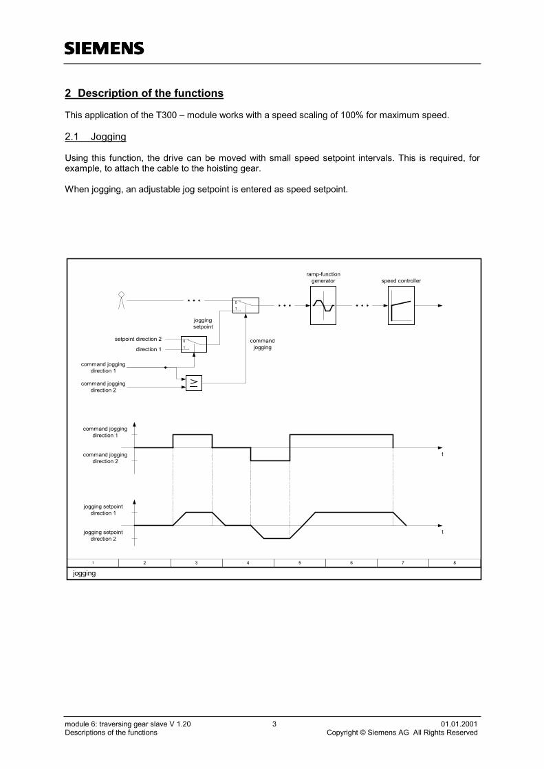
This application of the T300 – module works with a speed scaling of 100% for maximum speed.
2.1 Jogging
Using this function, the drive can be moved with small speed setpoint intervals. This is required, forexample, to attach the cable to the hoisting gear.
When jogging, an adjustable jog setpoint is entered as speed setpoint.
1 2 3 4 5 6 7 8
jogging
0
1
setpoint direction 2
direction 1
ramp-functiongenerator
jogging setpointdirection 2
jogging setpointdirection 1
command joggingdirection 1
command joggingdirection 2
command joggingdirection 1
command joggingdirection 2
01
speed controller
commandjogging
joggingsetpoint
t
t

ssss
module 6: traversing gear slave V 1.20 4 01.01.2001Descriptions of the functions Copyright © Siemens AG All Rights Reserved
2.2 Current distribution monitoring
This function can be used for slave drives (if it is practical). For a master-slave drive, it monitors thatthe total torque (current) is evenly distributed over both drives. However, as described above, this isnot always the case.
1 2 3 4 5 6 7 8
current distribution monitoring
peer to peer
CBP CBP
T300T300
CU CU
status wordbit 8
master slave
i-controllern-controllern-controller i-controller
n* i*
+-
n* n*
i*n*
ramp-functiongenerator
i* i*
ramp-functiongenerator
monitoring

ssss
module 6: traversing gear slave V 1.20 5 01.01.2001Descriptions of the functions Copyright © Siemens AG All Rights Reserved
2.3 Closed-loop control monitoring
This function continually monitors the speed setpoint and speed actual value, which, when the systemis operating correctly, must approximately correspond with one another.
This monitoring function responds, for example, if the closed-loop control goes to its current limit dueto an overload or a stalled drive, as the speed actual value can no longer follow the speed setpoint.
However, if the setpoint is less than the response difference, then there is a no signal output if the ac-tual value is missing. This fault is detected using the interrupted tachometer monitoring function of thebasic drives.
2.4 Speed-actual-actual-monitoring
This function can be used for speed-actual-actual monitoring if a drive is equipped with a speed actualvalue- and position actual value encoder.
If a drive has, in addition to a pulse encoder for the speed actual value, also a pulse encoder for theposition actual value, which is not mounted to the motor, but for example, to the drum, then monitoringcan be realized by evaluating the speeds supplied from both encoders. For instance, this can be usedto monitor the gearboxes or couplings for two rigidly coupled drives.
2.5 Overspeed monitoring
This monitoring function represents a software centrifugal switch. Using this monitoring function, asignal can be generated when a selectable speed is exceeded.
Values of between 110-150% of the maximum permissible operating speed are set for these over-speed protective devices. When an overspeed monitoring function responds, appropriate shutdownmechanisms can be initiated.
2.6 Zero speed signal
This function monitors the speed and responds if the selected limit is fallen below.
This signal is mainly used to close the brake. It is also used, for example, in the hoisting gear moduleto calculate the supplementary speed setpoint for load-dependent field weakening.

ssss
module 6: traversing gear slave V 1.20 6 01.01.2001Descriptions of the functions Copyright © Siemens AG All Rights Reserved
1 2 3 4 5 6 7 8
monitorings
actual speedvalue frombasic unit
signal to status word(technology) bit 3
system deviationfrom basic unit
actual speedvalue from
technology board(NAV)
actual speedvalue frombasic unit + -
signal to status word(technology) bit 2
signal to status word(technology) bit 1
signal to status word(technology) bit 4
speed actual-actual monitoring
closed-loop control monitoring
overspeed monitoring
zero speed signal

ssss
module 6: traversing gear slave V 1.20 7 01.01.2001Descriptions of the functions Copyright © Siemens AG All Rights Reserved
2.7 Position offset sensing with synchronization (of the offset)
This function is required if a slave drive should precisely follow a master drive, closed-loop positioncontrolled and the differential position actual value (offset) between the two drives which should bekept controlled, is to be set to an absolute position actual value at several points along the travel tocorrect erroneous measurements or erroneous/missing pulses. The offset must always be determinedif the relative position between two drives with respect to one another regarding their synchronizationmarks (Bero) must be sensed and controlled.
The actual position must be sensed for the closed-loop synchronous position control. In almost allcases, the speed actual value encoder mounted to the encoder can be used (a pulse encoder is re-quired, analog tachometers are not suitable).
Technology module T300 has, in the form of its terminal module, pulse encoder sensing inputs 1 and 2which can be read-in from a block at the same time.
For the closed-loop synchronous position control of two drives, the actual positions of both drives mustbe sensed. The pulse encoder, mounted to the motor for the speed actual values can be used for thispurpose.
The pulse encoder signals are fed to the basic drive for the speed actual sensing and to the technologymodule of the second drive for the position actual value sensing.
The position actual value of the drive must always be connected to pulse encoder sensing input 1 andthat of the master drive to pulse encoder sensing input 2 (for the slave).
For closed-loop position control of a drive, under certain circumstances, it is necessary to synchronizethe position actual value of these drives at shorter or longer intervals depending on the application.This, for example, always required, if errors in the position actual value sensing of the drive occur as aresult of the pulse encoder and the influence of noise and disturbances.
The synchronizing function has the task to correct this possibly erroneous position actual value. In thiscase, the reference to the sensed actual value position is re-referenced an absolute synchronizingmark.
When the synchronizing point is passed (synchronizing mark), this is sensed per hardware using aBero through the zero pulse encoder inputs.
The position actual values of both drives are then set to defined, actual position actual values whenpassing-over fixed synchronizing marks. The number of pulses which are received by the master andslave between passing over the two synchronizing marks is known as the offset.After the second drive has passed-over its synchronizing mark, the correct offset is determined. Thisnew offset replaces the old offset actual value which could have been possibly incorrect. It is now usedby the closed-loop synchronous operation control as new offset actual value which must be corrected.This corrects wheel slip or possible erroneous pulses.
In this case, synchronization means determining the offset. The synchronization has nothing to do withthe actual closed-loop control structure as when synchronizing, only the position difference actual valuehas to be corrected from the position of the synchronizing marks.
The synchronization and therefore the availability of synchronizing marks are not required for closed-loop synchronous position control, and should only be used when actually required.

1
01.01.01 hardware- and software structure for position- and synchronization control page: 8I&S IT PS Erl 35 V 1.22 3 4 5 6 7 8
technology board
communication board
S5/7
actualpositionvalue
evaluationsynchron
n-controller i-controller
nist
i*n*
X5M
X5N
SE
M T
T
basic unit
nist-monitoring
technology board
communication board
y=x
xy
X5M
X5N
SE
M T
T
basic unit
<0%
<0%
nist-monitoring
positiondifferenceevaluation
SYN viacontrol word
nist
sist
WSR2
WSR1
WSAUT
AAT
n-controller i-controller
nist
i*n*
+ -
WSSYN
+100%
-100%
setpoints
n**
AAT
nist
∆s
SDP
DPS
setpoints
peer to peer
offsetsync.
WSSYNMA
SMA SSL
WSSYNSL Sync.recei.
Syn1 Syn2
0
10
1
01
ramp-functiongenerator
ramp-functiongeneratorposition control
synchronizationcontroller
n**
hw-syn. via indexsignal input
hw-syn. viaindex pulse
input 0
1

ssss
module 6: traversing gear slave V 1.20 9 01.01.2001Descriptions of the functions Copyright © Siemens AG All Rights Reserved
2.8 Closed-loop synchronous operation control with offset as position difference
This function is required in conjunction with the offset sensing which was previously described, in orderto operate two drives in synchronous operation, which are separately closed-loop speed controlled andto correct the previously determined offset between the two drives.
When 2 drives are in synchronism, the slave drive follows the master drive, closed-loop position con-trolled in synchronism, with a position difference setpoint which has to be saved.
A position difference, which has to be defined (or a position difference equals 0) can be saved as offsetsetpoint.Initially, the two drives must be optically aligned (the slave drive by jogging). The difference actualvalue must then be manually set to 0. The drives can now be manually moved to the required offsetand the offset actual value saved as setpoint. The closed-loop position synchronous control is nowoperated with this setpoint.
The separately speed-controlled drives in this operating case must be coupled through the controlsystem via a synchronous operation controller in the slave drive. They must remain in position syn-chronism even if the load is unevenly distributed.
The synchronous operation controller is superimposed on the closed-loop speed control of the slavedrive. The inputs of the synchronous operation controller are the stored position difference actual valueas setpoint and the actual position difference value as actual value. The output of the synchronousoperation controller acts as supplementary setpoint at the setpoint input of the slave drive speed con-troller.
When closed-loop synchronous operation control is activated, and a position difference develops be-tween the drives, then the slave drive receives a supplementary speed setpoint via the synchronousoperation controller. This then operates this drive with the increased or decreased speed setpoint, untilthe position difference is again zero. The supplementary setpoint (the intervention of the supplemen-tary setpoint from the synchronous operation controller) should in this case be a maximum of 20% to30% of the max. drive speed.
The closed-loop synchronous operation control of a crane traversing gear will now be illustrated asexample.

1
01.01.01 signal flow chart synchronization control with synchronization overview page: 10I&S IT PS Erl 35 V 1.22 3 4 5 6 7 8
pulseencoder
evaluation
pulseencoder
evaluation
T
T
W
X
0
10
1
0
1
y=x
xy
speed setpoint (S7)
0%
0%
setpointenable (S7)
setpointenable (S7)
selectionjogging (S7)
selectionjogging (S7)
0%
offset save (S7)
position setpoint (S7)
slave
master
speed setpoint tobasic unit
position difference setpoint
enablesynchronizationcontroller (S7)
speed setpoint tobasic unit
i*
i*
synchronize
peer to peer
actual positionvalue
n-controller
n-controller
position synchronizationvalue (S7)
position synchronizationvalue(SL)(S7)
synchr. ∆s (S7)
joggingsetpoint
01
synchr.SL (S7)
synchr.MA (S7)
offsetevaluation
s1
s2
∆s
SYNC1recei.
SYNC2recei.
position synchronizationvalue(MA)(S7)
actual positiondifference value
s1
ssss
module 6: traversing gear slave V 1.20 11 01.01.2001Descriptions of the functions Copyright © Siemens AG All Rights Reserved
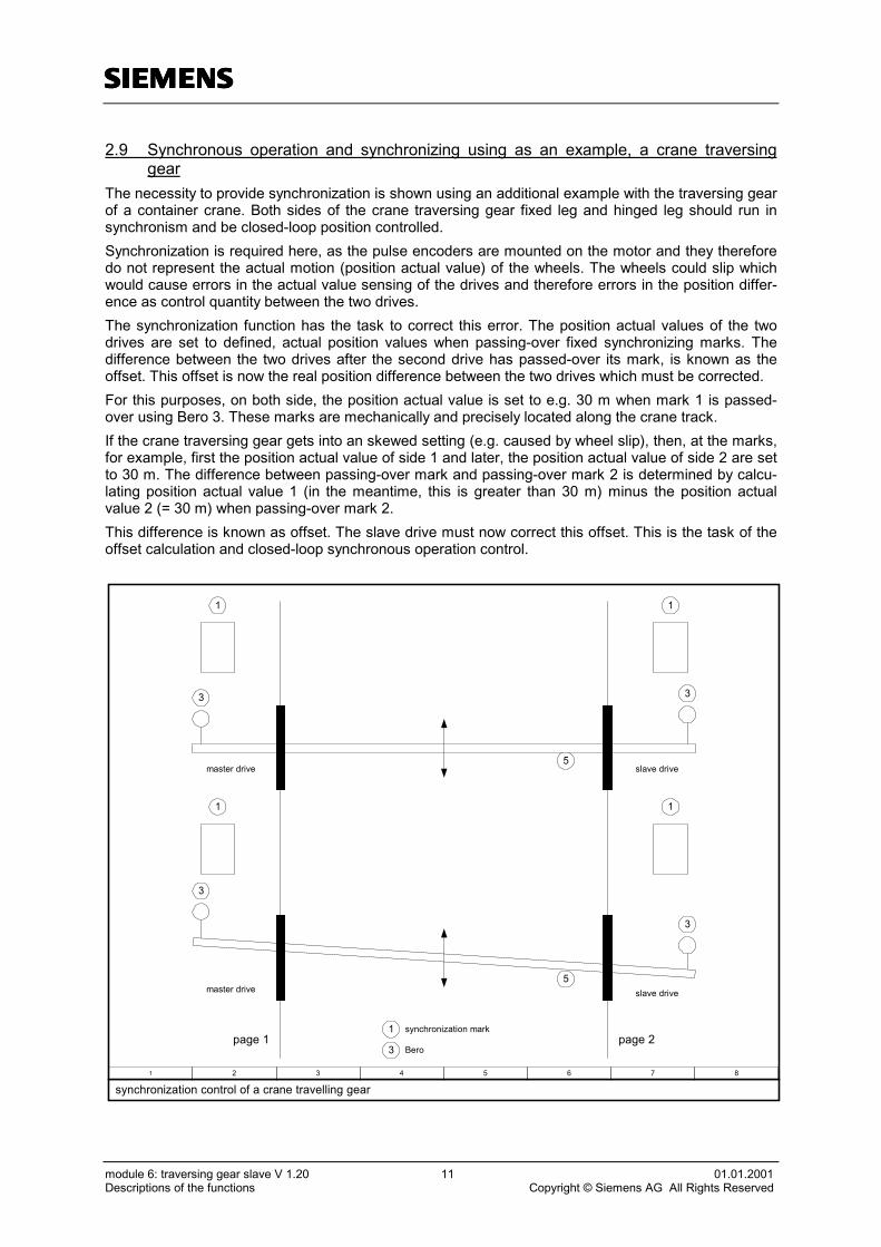
2.9 Synchronous operation and synchronizing using as an example, a crane traversinggear
The necessity to provide synchronization is shown using an additional example with the traversing gearof a container crane. Both sides of the crane traversing gear fixed leg and hinged leg should run insynchronism and be closed-loop position controlled.Synchronization is required here, as the pulse encoders are mounted on the motor and they thereforedo not represent the actual motion (position actual value) of the wheels. The wheels could slip whichwould cause errors in the actual value sensing of the drives and therefore errors in the position differ-ence as control quantity between the two drives.The synchronization function has the task to correct this error. The position actual values of the twodrives are set to defined, actual position values when passing-over fixed synchronizing marks. Thedifference between the two drives after the second drive has passed-over its mark, is known as theoffset. This offset is now the real position difference between the two drives which must be corrected.For this purposes, on both side, the position actual value is set to e.g. 30 m when mark 1 is passed-over using Bero 3. These marks are mechanically and precisely located along the crane track.If the crane traversing gear gets into an skewed setting (e.g. caused by wheel slip), then, at the marks,for example, first the position actual value of side 1 and later, the position actual value of side 2 are setto 30 m. The difference between passing-over mark and passing-over mark 2 is determined by calcu-lating position actual value 1 (in the meantime, this is greater than 30 m) minus the position actualvalue 2 (= 30 m) when passing-over mark 2.This difference is known as offset. The slave drive must now correct this offset. This is the task of theoffset calculation and closed-loop synchronous operation control.
1 2 3 4 5 6 7 8
synchronization control of a crane travelling gear
1
3
1 1
1
3
3
3
master drive
master drive
slave drive
slave drive
5
5
page 1 page 21
3
synchronization mark
Bero

Technology software modulefor the
module 6: traversing gear slave
closed-loop control of crane drives
process data, parameter, etc.

ssss
module 6: traversing gear slave V 1.20 2 01.01.2001process data, parameter, etc. Copyright © Siemens AG All Rights Reserved
STRUCTURE
3 process data, parameter, etc. ......................................................................... 3
3.1 allocation of process data.......................................................................................................... 3
3.2 allocation and description of the control bits.............................................................................. 5
3.3 allocation and description of the status bits...............................................................................8
3.4 parameter list........................................................................................................................... 11
3.5 faults and alarms ..................................................................................................................... 19
3.6 used abbreviations of function plans ....................................................................................... 20

ssss
module 6: traversing gear slave V 1.20 3 01.01.2001process data, parameter, etc. Copyright © Siemens AG All Rights Reserved
3 process data, parameter, etc.
3.1 allocation of process data
This application of the T300 is provided for 16 receive and send process data from or to the Communi-cation Board. The process data words 11-16 could only be configured and used with the EngineeringTool DriveES and the Communication Board CBP2. The following tables show the allocation of theprocess data words. Further on the tables show the goal or source of the process data words, i.e. theconnection of the process data (T300, base unit CU or Communication Board CB).
process data from automation system to T300 goal
PCD1 control word 1 STEU1 T300 / baseunit
PCD2 free T300PCD3 control word 2 STEU2 base unitPCD4 control word 1 (technology) STEU_TB1 T300PCD5 control word 2 (technology) STEU_TB2 T300PCD6 PCD6_Empf PZD6_Emp base unitPCD7 PCD7_Empf PZD7_Emp base unitPCD8 PCD8_Empf PZD8_Emp base unitPCD9 position synchronization value slave WSSYNSL T300PCD10 position synchronization value master WSSYNMA T300PCD11 PCD11_Empf PZD11_Emp base unitPCD12 PCD12_Empf PZD12_Emp base unitPCD13 PCD13_Empf PZD13_Emp base unitPCD14 PCD14_Empf PZD14_Emp base unitPCD15 PCD15_Empf PZD15_Emp base unit
PCD16 PCD16_Empf PZD16_Emp T300 / baseunit
process data from T300 to automation system sourcePCD1 status word 1 ZUST1 base unitPCD2 actual speed value XNGG base unitPCD3 status word 2 ZUST2 base unitPCD4 status word (technology) ZUST_TB T300PCD5 actual position value (slave) XSSL T300PCD6 actual position value (master) XSMA T300PCD7 PCD7_Send PZD7_Send base unitPCD8 PCD8_Send PZD8_Send base unitPCD9 PCD9_Send PZD9_Send base unitPCD10 PCD10_Send PZD10_Send base unitPCD11 PCD11_Send PZD11_Send base unitPCD12 PCD12_Send PZD12_Send base unitPCD13 PCD13_Send PZD13_Send base unitPCD14 PCD14_Send PZD14_Send base unitPCD15 PCD15_Send PZD15_Send base unitPCD16 PCD16_Send PZD16_Send base unit

ssss
module 6: traversing gear slave V 1.20 4 01.01.2001process data, parameter, etc. Copyright © Siemens AG All Rights Reserved
This application of the T300 is provided for 16 receive and send process data from or to the base unit.The process data, which aren’t used in this application, are connected between the base unit and theCommunication Board. The following tables show the allocation of the process data words. Further onthe tables show the goal or source of the process data words, i.e. the connection of the process data(T300, base unit CU or Communication Board CB).
process data from T300 to base unit SourcePCD1 control word 1 STEU1 CBPCD2 speed setpoint WNGG T300PCD3 control word 2 STEU2 CBPCD4 free T300PCD5 free T300PCD6 PCD6_Empf PZD6_Emp CBPCD7 PCD7_Empf PZD7_Emp CBPCD8 PCD8_Empf PZD8_Emp CBPCD9 free T300PCD10 free T300PCD11 PCD11_Empf PZD11_Emp CBPCD12 PCD12_Empf PZD12_Emp CBPCD13 PCD13_Empf PZD13_Emp CBPCD14 PCD14_Empf PZD14_Emp CBPCD15 PCD15_Empf PZD15_Emp CBPCD16 PCD16_Empf PZD16_Emp CB
process data from base unit to T300 goalPCD1 status word 1 ZUST1 CBPCD2 actual speed value XNGG T300 / CBPCD3 status word 2 ZUST2 CBPCD4 current setpoint ZUST_TB T300PCD5 setpoint-actual value difference XS1 T300PCD6 free T300PCD7 PCD7_Send PZD7_Send CBPCD8 PCD8_Send PZD8_Send CBPCD9 PCD9_Send PZD9_Send CBPCD10 PCD10_Send PZD10_Send CBPCD11 PCD11_Send PZD11_Send CBPCD12 PCD12_Send PZD12_Send CBPCD13 PCD13_Send PZD13_Send CBPCD14 PCD14_Send PZD14_Send CBPCD15 PCD15_Send PZD15_Send T300 / CBPCD16 PCD16_Send PZD16_Send T300 / CB
ssss
module 6: traversing gear slave V 1.20 5 01.01.2001process data, parameter, etc. Copyright © Siemens AG All Rights Reserved
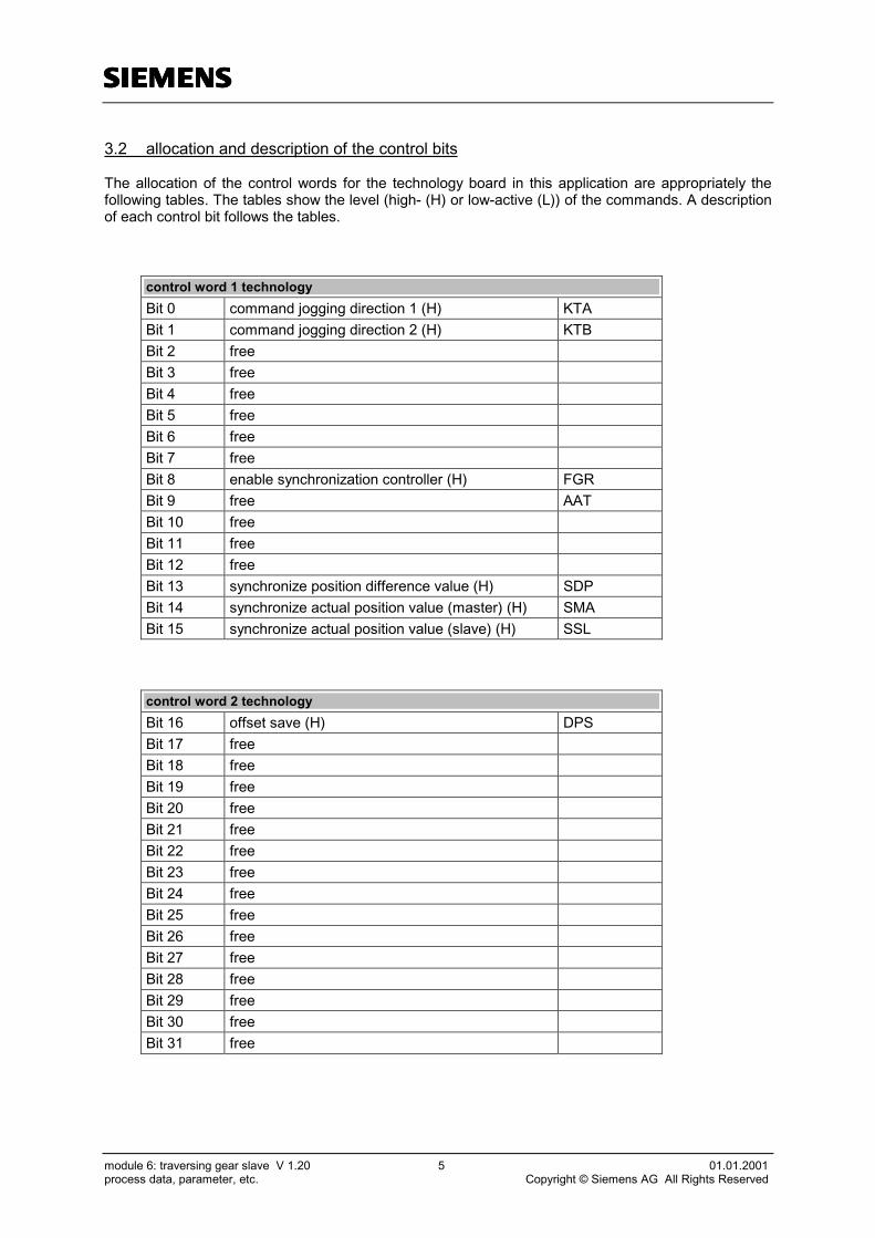
3.2 allocation and description of the control bits
The allocation of the control words for the technology board in this application are appropriately thefollowing tables. The tables show the level (high- (H) or low-active (L)) of the commands. A descriptionof each control bit follows the tables.
control word 1 technologyBit 0 command jogging direction 1 (H) KTABit 1 command jogging direction 2 (H) KTBBit 2 freeBit 3 freeBit 4 freeBit 5 freeBit 6 freeBit 7 freeBit 8 enable synchronization controller (H) FGRBit 9 free AATBit 10 freeBit 11 freeBit 12 freeBit 13 synchronize position difference value (H) SDPBit 14 synchronize actual position value (master) (H) SMABit 15 synchronize actual position value (slave) (H) SSL
control word 2 technologyBit 16 offset save (H) DPSBit 17 freeBit 18 freeBit 19 freeBit 20 freeBit 21 freeBit 22 freeBit 23 freeBit 24 freeBit 25 freeBit 26 freeBit 27 freeBit 28 freeBit 29 freeBit 30 freeBit 31 free

ssss
module 6: traversing gear slave V 1.20 6 01.01.2001process data, parameter, etc. Copyright © Siemens AG All Rights Reserved
Bit 0: command jogging direction 1 (H „jogging direction 1“ / L „jogging direction 1 off“)
A high-signal sets the speed setpoint to the base unit to the value, parameterized via the parameterH333.The setpoint should be for example positive for the direction 1. A low-signal doesn’t select aspeed setpoint for jogging.
Bit 1: command jogging direction 1 (H „jogging direction 1“ / L „jogging direction 1 off“)
A high-signal sets the speed setpoint to the base unit to the value, parameterized via the parameterH332.The setpoint should be for example negative for the direction 2 (reverse to direction 1). “Com-mand jogging direction 1” has priority, if “command jogging direction 1” and “command jogging direc-tion 2” are set together (high). A low-signal doesn’t select a speed setpoint for jogging.
Bit 8: enable synchronization controller (H „enable synchronization controller“ / L „disable“)
A high-signal enables the synchronization controller. A low-signal disables the synchronization control-ler.
Bit 13: synchronize position difference value (H „synchronize” / L „no synchronize“)
A high-signal sets the position difference value to 0.
Bit 14: synchronize actual position value (master) (H „synchronize” / L „no synchronize“)
A high-signal sets the actual position value of the master drive to the position synchronization value(PZD 10) given via automation system.
Bit 15: synchronize actual position value (slave) (H „synchronize” / L „no synchronize“)
A high-Signal sets the actual position value of the slave drive to the position synchronization value(PZD 9) given via automation system.
Bit 16: offset save (H „offset save“)
A High-Signal saves the actual position difference value. This value is given as position difference set-point for the closed-loop synchronous, if parameter H281 is set to 1.
ssss
module 6: traversing gear slave V 1.20 7 01.01.2001process data, parameter, etc. Copyright © Siemens AG All Rights Reserved
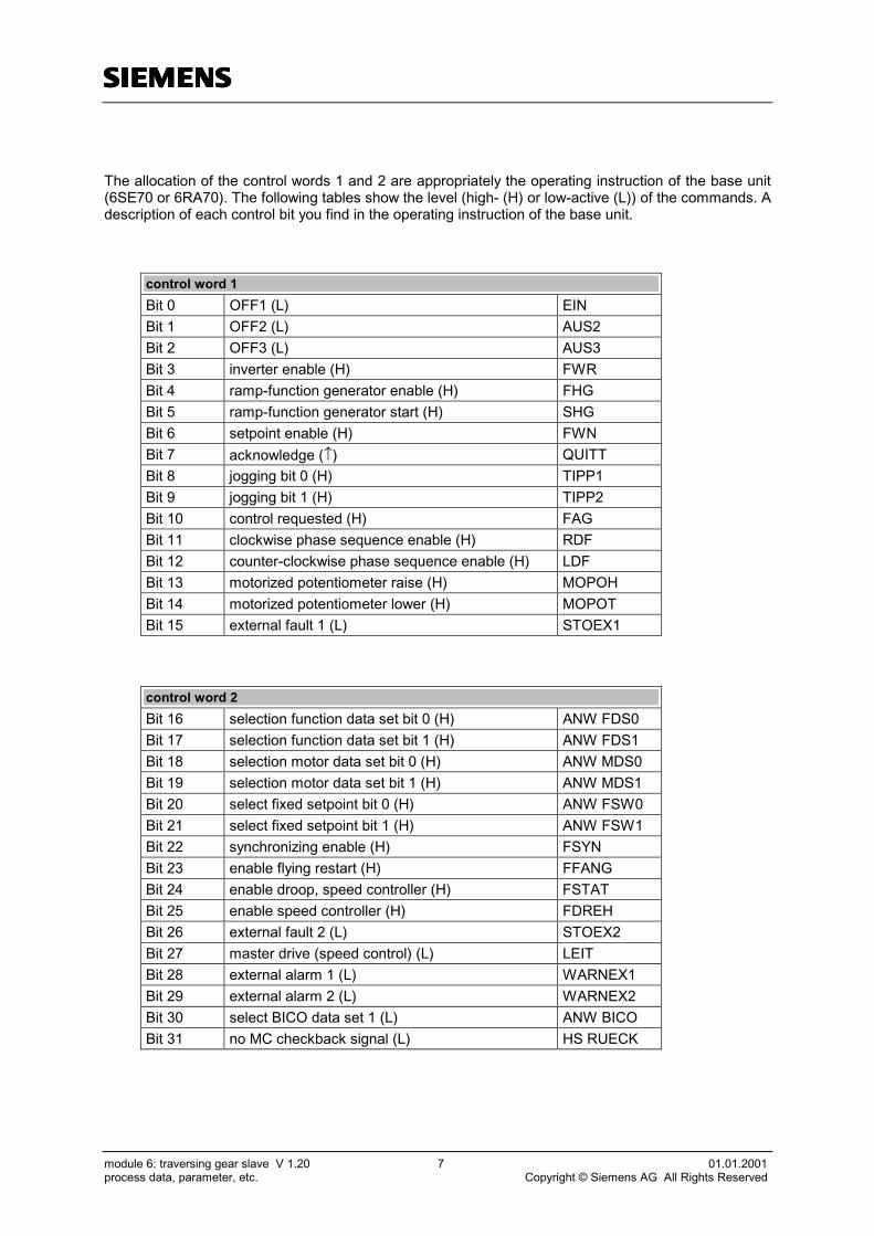
The allocation of the control words 1 and 2 are appropriately the operating instruction of the base unit(6SE70 or 6RA70). The following tables show the level (high- (H) or low-active (L)) of the commands. Adescription of each control bit you find in the operating instruction of the base unit.
control word 1Bit 0 OFF1 (L) EINBit 1 OFF2 (L) AUS2Bit 2 OFF3 (L) AUS3Bit 3 inverter enable (H) FWRBit 4 ramp-function generator enable (H) FHGBit 5 ramp-function generator start (H) SHGBit 6 setpoint enable (H) FWNBit 7 acknowledge (↑) QUITTBit 8 jogging bit 0 (H) TIPP1Bit 9 jogging bit 1 (H) TIPP2Bit 10 control requested (H) FAGBit 11 clockwise phase sequence enable (H) RDFBit 12 counter-clockwise phase sequence enable (H) LDFBit 13 motorized potentiometer raise (H) MOPOHBit 14 motorized potentiometer lower (H) MOPOTBit 15 external fault 1 (L) STOEX1
control word 2Bit 16 selection function data set bit 0 (H) ANW FDS0Bit 17 selection function data set bit 1 (H) ANW FDS1Bit 18 selection motor data set bit 0 (H) ANW MDS0Bit 19 selection motor data set bit 1 (H) ANW MDS1Bit 20 select fixed setpoint bit 0 (H) ANW FSW0Bit 21 select fixed setpoint bit 1 (H) ANW FSW1Bit 22 synchronizing enable (H) FSYNBit 23 enable flying restart (H) FFANGBit 24 enable droop, speed controller (H) FSTATBit 25 enable speed controller (H) FDREHBit 26 external fault 2 (L) STOEX2Bit 27 master drive (speed control) (L) LEITBit 28 external alarm 1 (L) WARNEX1Bit 29 external alarm 2 (L) WARNEX2Bit 30 select BICO data set 1 (L) ANW BICOBit 31 no MC checkback signal (L) HS RUECK

ssss
module 6: traversing gear slave V 1.20 8 01.01.2001process data, parameter, etc. Copyright © Siemens AG All Rights Reserved
3.3 allocation and description of the status bits
The allocation of the status word of the technology board in this application is appropriately the follow-ing table. The table shows the level (high- (H) or low-active (L)) of the signals. A description of eachstatus bit follow the table.
status word technologyBit 0 signal fault encoder (L) FIGSBit 1 signal speed setpoint-actual value diff. saved (L) MXNDSBit 2 signal overspeed saved (L) MXNGSBit 3 signal speed = 0 (H) MXN0
Bit 4 signal fault speed actual-actual value difference(L) FIGNSS
Bit 5 signal fault coupling T300 to base unit (L) FKGERSBit 6 signal fault coupling to automation system (L) FKS5SBit 7 freeBit 8 signal fault current distribution difference (L) FIVERSBit 9 signal fault coupling peer to peer (L) FKPPSBit 10 freeBit 11 freeBit 12 free MXNFSBit 13 signal RFG-output = RFG-input (H) KQEBit 14 signal fault offset evaluation (L) FVESBit 15 free AWR
Bit 0: signal fault encoder (H „no fault“ / L „fault“)
A low-signal shows a configuring error of the encoder. The bit is just reset to high-level via the ac-knowledge command.
Bit 1: signal speed setpoint-actual value difference saved (H „no speed setpoint-actual valuedifference saved“ / L „speed setpoint-actual value difference saved“)
A low-signal shows a deviation of the actual speed compared to the speed setpoint, which is largerthan the value parameterized via H456/H457. A larger deviation is saved and the bit is just reset tohigh-level via the acknowledge command.
Bit 2: signal overspeed saved (H „no overspeed“ / L „overspeed“)
A low-signal shows, if the actual speed is greater than the limit parameterized via H459/H460. Agreater actual speed is saved and the bit is just reset to high-level via the acknowledge command.
Bit 3: signal speed = 0 (H „speed = 0“ / L „speed <> 0“)
A high-signal shows a deviation of the actual speed compared to speed 0, which is larger than thevalue parameterized via H461/H462.

ssss
module 6: traversing gear slave V 1.20 9 01.01.2001process data, parameter, etc. Copyright © Siemens AG All Rights Reserved
Bit 4: signal fault speed actual-actual deviation (H „no fault“ / L „fault“)
A low-signal shows a deviation of the actual speed (T300) compared to the actual speed from the baseunit, which is larger than the value parameterized via H466/H467. A larger deviation is saved and thebit is just reset to high-level via the acknowledge command.
Bit 5: signal fault coupling T300 to base unit (H „no fault“ / L „fault“)
A low-signal shows an error between the coupling T300 / base unit. The bit is just reset to high-level viathe acknowledge command.
Bit 6: signal fault coupling to automation system (H „no fault“ / L „fault“)
A low-signal shows an error between the coupling T300 / automation system (Communication Board).The bit is just reset to high-level via the acknowledge command.
Bit 8: signal fault current distribution difference (H „no fault“ / L „fault“)
A low-signal shows a deviation of the current setpoint/slave compared to the current setpoint/master,which is larger than the value prameterized via H469/H470. A larger deviation is saved and the bit isjust reset to high-level via the acknowledge command. This monitoring is only active if synchronism isselected (control word 1 (technology) bit 12) (slave drive).
Bit 9: signal fault coupling peer to peer (H „no fault“ / L „fault“)
A low-signal shows an error between peer-to-peer-coupling. The bit is just reset to high-level via theacknowledge command.
Bit 13: signal RFG-output = RFG-input (H „RFG-output = RFG-input“ / L „RFG-active or locked“)
A high-signal shows, if the ramp-function generator output is equal to the ramp-function generator input(the ramp-function generator isn’t active.). A low-level shows, if the RFG is active or locked.
Bit 14: signal fault offset evaluation (H „no fault“ / L „fault“)
A low-signal shows an error of the offset evaluation or the evaluated offset is larger than the value pa-rameterized via H189. A larger offset or an error is saved and the bit is just reset to high-level with theacknowledge command
ssss
module 6: traversing gear slave V 1.20 10 01.01.2001process data, parameter, etc. Copyright © Siemens AG All Rights Reserved
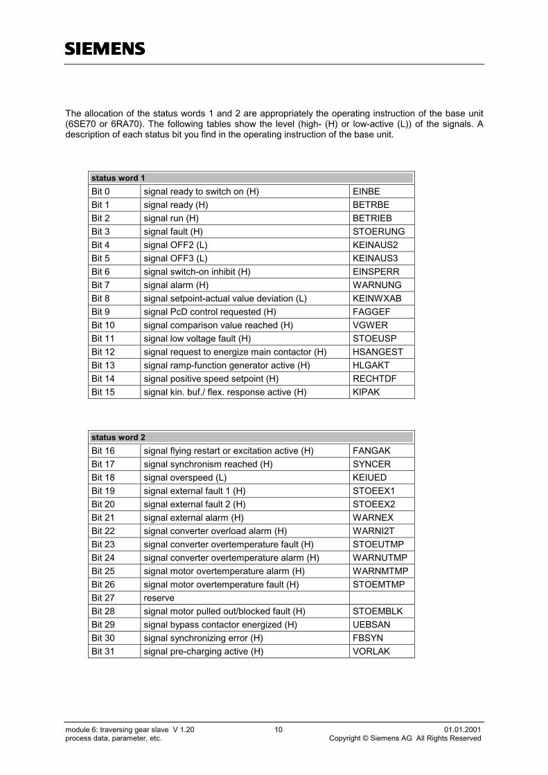
The allocation of the status words 1 and 2 are appropriately the operating instruction of the base unit(6SE70 or 6RA70). The following tables show the level (high- (H) or low-active (L)) of the signals. Adescription of each status bit you find in the operating instruction of the base unit.
status word 1Bit 0 signal ready to switch on (H) EINBEBit 1 signal ready (H) BETRBEBit 2 signal run (H) BETRIEBBit 3 signal fault (H) STOERUNGBit 4 signal OFF2 (L) KEINAUS2Bit 5 signal OFF3 (L) KEINAUS3Bit 6 signal switch-on inhibit (H) EINSPERRBit 7 signal alarm (H) WARNUNGBit 8 signal setpoint-actual value deviation (L) KEINWXABBit 9 signal PcD control requested (H) FAGGEFBit 10 signal comparison value reached (H) VGWERBit 11 signal low voltage fault (H) STOEUSPBit 12 signal request to energize main contactor (H) HSANGESTBit 13 signal ramp-function generator active (H) HLGAKTBit 14 signal positive speed setpoint (H) RECHTDFBit 15 signal kin. buf./ flex. response active (H) KIPAK
status word 2Bit 16 signal flying restart or excitation active (H) FANGAKBit 17 signal synchronism reached (H) SYNCERBit 18 signal overspeed (L) KEIUEDBit 19 signal external fault 1 (H) STOEEX1Bit 20 signal external fault 2 (H) STOEEX2Bit 21 signal external alarm (H) WARNEXBit 22 signal converter overload alarm (H) WARNI2TBit 23 signal converter overtemperature fault (H) STOEUTMPBit 24 signal converter overtemperature alarm (H) WARNUTMPBit 25 signal motor overtemperature alarm (H) WARNMTMPBit 26 signal motor overtemperature fault (H) STOEMTMPBit 27 reserveBit 28 signal motor pulled out/blocked fault (H) STOEMBLKBit 29 signal bypass contactor energized (H) UEBSANBit 30 signal synchronizing error (H) FBSYNBit 31 signal pre-charging active (H) VORLAK

ssss
module 6: traversing gear slave V 1.20 11 01.01.2001process data, parameter, etc. Copyright © Siemens AG All Rights Reserved
3.4 parameter list
parameter block(SIMADYN) parameter description data start-up
setting default function-plan
receive from Communication Board CB
d 001 ECB10.Y1 control word 1 from CB Type: V2 page 1/2d 002 ECB10.Y2 PCD 2 from CB (no connection) Type: N2 page 1/2d 003 ECB10.Y3 control word 2 from CB Type: V2 page 1/2d 004 ECB10.Y4 control word 1 technology from CB Type: V2 page 1/2d 005 ECB10.Y5 control word 2 technology from CB Type: V2 page 1/2d 006 ECB10.Y6 PCD 6 from CB (to base unit CU connected) Type: N2 page 1/2d 007 ECB10.Y7 PCD 7 from CB (to base unit CU connected) Type: N2 page 1/2d 008 ECB10.Y8 PCD 8 from CB (to base unit CU connected) Type: N2 page 1/2d 009 ECB170.Y1 position synchronization value (slave) from CB Type: N2 page 1/2d 010 ECB170.Y2 position synchronization value (master) from CB Type: N2 page 1/2d 011 ECB170.Y3 PCD 11 from CB (to base unit CU connected) Type: N2 page 1/2d 012 ECB170.Y4 PCD 12 from CB (to base unit CU connected) Type: N2 page 1/2d 013 ECB170.Y5 PCD 13 from CB (to base unit CU connected) Type: N2 page 1/2d 014 ECB170.Y6 PCD 14 from CB (to base unit CU connected) Type: N2 page 1/2d 015 ECB170.Y7 PCD 15 from CB (to base unit CU connected) Type: N2 page 1/2d 016 ECB170.Y8 PCD 16 from CB (to base unit CU connected) Type: N2 page 1/2
H 017 ECB205.I selection source for control word 1(0 = from CB / 1 = from digital inputs)
Type: B1Min: 0Max: 1
0 page 1/6
H 018 ECB40.X2 evaluation PCD 2 from CB(no connection)
Type: N2Min: -200%Max: 199,9%
100 % page 1/2
H 020 ECB245.Y selection source for control word 1 technology(0 = from CB / 1 = from digital inputs)
Type: B1Min: 0Max: 1
0 page 1/6
H 021 ECB265.Y selection source for control word 2 technology(0 = from CB / 1 = from digital inputs)
Type: B1Min: 0Max: 1
0 page 1/6
H 022 ECB120.X2 evaluation PCD 6 from CB(to base unit CU connected)
Type: N2Min: -200%Max: 199,9%
100 % page 1/2
H 023 ECB140.X2 evaluation PCD 7 from CB(to base unit CU connected)
Type: N2Min: -200%Max: 199,9%
100 % page 1/2
H 024 ECB160.X2 evaluation PCD 8 from CB(to base unit CU connected)
Type: N2Min: -200%Max: 199,9%
100 % page 1/2
H 025 ECB180.X2 evaluation position synchronization value (Slave)from CB
Type: N2Min: -200%Max: 199,9%
100 % page 1/2
H 026 ECB200.X2 evaluation position synchronization value (mas-ter) from CB
Type: N2Min: -200%Max: 199,9%
100 % page 1/2
H 027 ECB220.X2 evaluation PCD 11 from CB(to base unit CU connected)
Type: N2Min: -200%Max: 199,9%
100 % page 1/2
H 028 ECB240.X2 evaluation PCD 12 from CB(to base unit CU connected)
Type: N2Min: -200%Max: 199,9%
100 % page 1/2
H 029 ECB260.X2 evaluation PCD 13 from CB(to base unit CU connected)
Type: N2Min: -200%Max: 199,9%
100 % page 1/2
H 030 ECB280.X2 evaluation PCD 14 from CB(to base unit CU connected)
Type: N2Min: -200%Max: 199,9%
100 % page 1/2
H 031 ECB300.X2 evaluation PCD 15 from CB(to base unit CU connected)
Type: N2Min: -200%Max: 199,9%
100 % page 1/2

ssss
module 6: traversing gear slave V 1.20 12 01.01.2001process data, parameter, etc. Copyright © Siemens AG All Rights Reserved
parameter block(SIMADYN) parameter description data start-up
setting default function-plan
H 032 ECB320.X2 evaluation PCD 16 from CB(to base unit CU connected)
Type: N2Min: -200%Max: 199,9%
100 % page 1/2
d 033 ECB205.Y control word 1 to base unit CU Type: V2 page 3/1d 035 ECB60.Y control word 2 to base unit CU Type: V2 page 3/1d 036 ECB245.Y actual control word 1 technology Type: V2 page 3/5d 037 ECB265.Y actual control word 2 technology Type: V2 page 3/5
receive from base unit CU
d 065 EGG10.Y1 status word 1 from base unit CU Type: V2 page 5/2d 066 EGG10.Y2 actual speed value from base unit CU Type: N2 page 5/2d 067 EGG10.Y3 status word 2 from base unit CU Type: V2 page 5/2d 068 EGG10.Y4 current setpoint from base unit CU Type: N2 page 5/2d 069 EGG10.Y5 setpoint-actual value difference from CU Type: N2 page 5/2d 070 EGG10.Y6 PCD 6 from base unit (no connection) Type: N2 page 5/2d 071 EGG10.Y7 PCD 7 from base unit (to CB connected) Type: N2 page 5/2d 072 EGG10.Y8 PCD 8 from base unit (to CB connected) Type: N2 page 5/2d 073 EGG100.Y1 PCD 9 from base unit (to CB connected) Type: N2 page 5/2d 074 EGG100.Y2 PCD 10 from base unit (to CB connected) Type: N2 page 5/2d 075 EGG100.Y3 PCD 11 from base unit (to CB connected) Type: N2 page 5/2d 076 EGG100.Y4 PCD 12 from base unit (to CB connected) Type: N2 page 5/2d 077 EGG100.Y5 PCD 13 from base unit (to CB connected) Type: N2 page 5/2d 078 EGG100.Y6 PCD 14 from base unit (to CB connected) Type: N2 page 5/2d 079 EGG100.Y7 PCD 15 from base unit (to CB connected) Type: N2 page 5/2d 080 EGG100.Y8 PCD 16 from base unit (to CB connected) Type: N2 page 5/2d 081 EGG20.Y status word 1 to CB Type: V2 page 5/6
H 082 EGG30.X2 evaluation actual speed value from base unitCU
Type: N2Min: -200%Max: 199,9%
100 % page 5/3
d 083 EGG40.Y status word 2 to CB Type: V2 page 5/6
H 084 EGG50.X2 evaluation current setpoint from base unit CUType: N2Min: -200%Max: 199,9%
100 % page 5/3
H 085 EGG60.X2 evaluation setpoint-actual value difference fromCU
Type: N2Min: -200%Max: 199,9%
100 % page 5/3
H 086 EGG70.X2 evaluation PCD 6 from base unit(no connection)
Type: N2Min: -200%Max: 199,9%
100 % page 5/3
H 087 EGG80.X2 evaluation PCD 7 from base unit(to CB connected)
Type: N2Min: -200%Max: 199,9%
100 % page 5/3
H 088 EGG90.X2 evaluation PCD 8 from base unit(to CB connected)
Type: N2Min: -200%Max: 199,9%
100 % page 5/3
H 089 EGG110.X2 evaluation PCD 9 from base unit(to CB connected)
Type: N2Min: -200%Max: 199,9%
100 % page 5/3
H 090 EGG120.X2 evaluation PCD 10 from base unit(to CB connected)
Type: N2Min: -200%Max: 199,9%
100 % page 5/3
H 091 EGG130.X2 evaluation PCD 11 from base unit(to CB connected)
Type: N2Min: -200%Max: 199,9%
100 % page 5/3
H 092 EGG140.X2 evaluation PCD 12 from base unit(to CB connected)
Type: N2Min: -200%Max: 199,9%
100 % page 5/3
H 093 EGG150.X2 evaluation PCD 13 from base unit(to CB connected)
Type: N2Min: -200%Max: 199,9%
100 % page 5/3
H 094 EGG160.X2 evaluation PCD 14 from base unit(to CB connected)
Type: N2Min: -200%Max: 199,9%
100 % page 5/3

ssss
module 6: traversing gear slave V 1.20 13 01.01.2001process data, parameter, etc. Copyright © Siemens AG All Rights Reserved
parameter block(SIMADYN) parameter description data start-up
setting default function-plan
H 095 EGG170.X2 evaluation PCD 15 from base unit(to CB connected)
Type: N2Min: -200%Max: 199,9%
100 % page 5/3
H 096 EGG180.X2 evaluation PCD 16 from base unit(to CB connected)
Type: N2Min: -200%Max: 199,9%
100 % page 5/3
analog inputs
H 133 AE20.X2 evaluation analog input A(terminal SE 300 X5/501,502)
Type: N2Min: -200%Max: 199,9%
100 % page 7/2
H 134 AE50.X2 evaluation analog input B(terminal SE 300 X5/503,504)
Type: N2Min: -200%Max: 199,9%
100 % page 7/2
H 135 AE80.X2 evaluation analog input C(terminal SE 300 X5/505,506)
Type: N2Min: -200%Max: 199,9%
100 % page 7/2
H 136 AE110.X2 evaluation analog input A(terminal SE 300 X5/507,508)
Type: N2Min: -200%Max: 199,9%
100 % page 7/2
H 137 AE30.X2 offset analog input AType: N2Min: -200%Max: 199,9%
0 % page 7/3
H 138 AE60.X2 offset analog input BType: N2Min: -200%Max: 199,9%
0 % page 7/3
H 139 AE90.X2 offset analog input CType: N2Min: -200%Max: 199,9%
0 % page 7/3
H 140 AE120.X2 offset analog input DType: N2Min: -200%Max: 199,9%
0 % page 7/3
d 141 AE30.Y analog input A after evaluation and offset Type: N2 page 7/3d 142 AE60.Y analog input B after evaluation and offset Type: N2 page 7/3d 143 AE90.Y analog input C after evaluation and offset Type: N2 page 7/3d 144 AE120.Y analog input D after evaluation and offset Type: N2 page 7/3
receive peer to peer
d 145 EPP20.Y speed setpoint (from master) Type: N2 page 8/3d 146 EPP30.Y current setpoint (from master) Type: N2 page 8/3
actual position and speed sensing
H 165 ERX350.IT1
selection type of encoder input 1(terminal SE 300 X5/531,539)Bit 0-3: setting for digital filter 0HxxxX0: 500 kHz 1: no filter 2: 2 MHz3: 500 kHz 4: 126 kHz 5: 62,5 kHzBit 4-7: type of encoder 0HxxXx0: encoder with 2 tracks, displaced by 90 degrees1: seperate tracks for forward and backward pulse2: index signal from base unit bus4: tracks A+B from base unit bus6: tracks A,B,index signal from base unit busBit 8-11: coarse pulse evaluation 0HxXxx0: no coarse pulse evaluation1: coarse pulse type 12: coarse pulse type 2 (s. HW-description T300)Bit 12-15: evaluation synchroniz. signal 0HXxxx0: not dependent on the direction of rotation1: dependent on the direction of rotation, i.e. positive edge at
positive speed, negative edge at negative speed
Type: V2Min: 0Max: FFFF
0H0000 page 9/3

ssss
module 6: traversing gear slave V 1.20 14 01.01.2001process data, parameter, etc. Copyright © Siemens AG All Rights Reserved
parameter block(SIMADYN) parameter description data start-up
setting default function-plan
H 166 ERX350.IT2
selection type of encoder input 2(terminal SE 300 X5/541,549)Bit 0-3: setting for digital filter 0HxxxX0: 500 kHz 1: no filter 2: 2 MHz3: 500 kHz 4: 126 kHz 5: 62,5 kHzBit 4-7: type of encoder 0HxxXx0: encoder with 2 tracks, displaced by 90 degrees1: seperate tracks for forward and backward pulseBit 8-11: coarse pulse evaluation 0HxXxx0: no coarse pulse evaluation1: coarse pulse type 12: coarse pulse type 2 (s. HW-description T300)Bit 12-15: evaluation synchroniz. signal 0HXxxx0: not dependent on the direction of rotation1: dependent on the direction of rotation, i.e. positive edge at
positive speed, negative edge at negative speed
Type: V2Min: 0Max: FFFF
0H0000 page 9/3
H 167 ERX350.PR1 number of pulses per revolution input 1Type: O2Min: 0Max: 32767
500 page 9/3
H 168 ERX350.PR2 number of pulses per revolution input 2Type: O2Min: 0Max: 32767
500 page 9/3
H 169 ERX350.RS1 nominal speed input 1 (in 1/min)Type: I2Min: -32768Max: 32767
1000 page 9/3
H 170 ERX350.RS2 nominal speed input 2 (in 1/min)Type: I2Min: -32768Max: 32767
1000 page 9/3
H 171 ERX350.RP1pulse count for 100% position, input 1(number of pulses, which correspond to 100% position. Atencoder with 2 tracks, displaced by 90 degrees you have toconsider the pulse quadrupling)
Type: O4Min: 0Max: 2,1x10⁹
2000000 page 9/3
H 173 ERX350.RP2pulse count for 100% position, input 2(number of pulses, which correspond to 100% position. Atencoder with 2 tracks, displaced by 90 degrees you have toconsider the pulse quadrupling)
Type: O4Min: 0Max: 2,1x10⁹
2000000 page 9/3
H 175 ERX350.CW1
evaluation setting input input 1Bit 0-7: stillstand limit 0HxxXX0: 4 sampling timesn: actual speed set to 0 after n sampling timesBit 8: evaluation setting input S1 and SP1input SV1 gets offset function0: YP1=SV1 at S1=1 or SP1=1 and synchron. edge 11: YP1=YP1-SV1 at S1=1 or SP1=1 and synchron. edge 1Bit 12: evaluation setting input SP10: YP1 =SV1 at SP1=1 and synchronization1: YP1=YP1-SV1 at SP1=1 and synchronization
Type: V2Min: 0Max: FFFF
0H0000 page 9/3
H 176 ERX350.CW2
evaluation setting input input 2Bit 0-7: stillstand limit 0HxxXX0: 4 sampling timesn: actual speed set to 0 after n sampling timesBit 8: evaluation setting input S2 and SP2input SV2 gets offset function0: YP2=SV2 at S2=1 or SP2=1 and synchron. edge 21: YP2=YP2-SV2 at S2=1 or SP2=1 and synchron. edge 2Bit 12: evaluation setting input SP20: YP2 =SV2 at SP2=1 and synchronization1: YP2=YP2-SV2 at SP2=1 and synchronization
Type: V2Min: 0Max: FFFF
0H0000 page 9/3
d 179 ERX160.Y actual position difference value (track 1 - 2) Type: N2 page 9/1d 180 ERX40.Y actual position value (track 1) Type: N2 page 9/1d 181 ERX100.Y actual position value (track 2) Typ: N2 page 9/1d 182 ERX 180.Y synchronization value (position difference) Type: N2 page 9/3d 183 ERX60.Y synchronization value (actual position track. 1) Type: N2 page 9/3d 184 ERX120.Y synchronization value (actual position track. 2) Typ: N2 page 9/3
H 185 ERX510.X2 evaluation actual speed value (track 1)Type: N2Min: -200%Max: 199,9%
100 % page 9/6
H 186 ERX520.T filtering time actual speed value(track 1)
Type: R2Min: 10msMax:163840ms
40 ms page 9/6
d 187 ERX520.Y actual speed value from position encoder(track 1)
Type: N2 page 9/7

ssss
module 6: traversing gear slave V 1.20 15 01.01.2001process data, parameter, etc. Copyright © Siemens AG All Rights Reserved
parameter block(SIMADYN) parameter description data start-up
setting default function-plan
d 188 ERX440.Y actual offset value Typ: N2 page 9/7
H 189 ERX380.X2 Maximum correction of the offset (at larger evalu-ated offset a fault is generated)
Typ: N2Min: -200%Max: 199,9%
0,5 % page 9/6
d 190 ERX400.Q offset correct evaluated Typ: N2 page 9/8
H 191 ERX540.X Position difference from synchronization markto reset the offset evaluation
Typ: N2Min: -200%Max: 199,9%
3,7 % page 9/6
synchronization controller
d 280 GLR40.Y saved position difference setpoint Type: N2 page 10/3
H 281 GLR60.ISelection source for position difference setpoint(0 = position difference setpoint is 0% / 1 = saved positiondifference setpoint)
Type: B1Min: 0Max: 1
0 page 10/3
H 282 GLR70.LU upper limit synchronization controller(max. additional positive setpoint of synchronization controller)
Type: N2Min: -200%Max: 199,9%
5 % page 10/3
H 283 GLR70.LLlower limit synchronization controller(max. additional negative setpoint of synchronization control-ler)
Type: N2Min: -200%Max: 199,9%
-5 % page 10/3
H 284 GLR70.KP gain KP synchronization controllerType: E2Min: -256Max: 255
30 page 10/3
H 285 GLR70.TN integral time synchronization controllerType: R2Min: 10msMax:163840ms
1000 ms page 10/3
H 286 GLR70.HI changeover P- or PI-controller(0 = PI-controller / 1 = P-controller)
Type: B1Min: 0Max: 1
1 page 10/3
d 290 GLR70.Y changeover P- or PI-controller(additional speed setpoint)
Type: N2 page 10/4
H 291 GLR80.A1 polygon curve value X1 (synchronization control)Typ: N2Min: -200%Max: 199,9%
0 % page 10/3
H 292 GLR80.B1 polygon curve value Y1 (synchronization control)Typ: N2Min: -200%Max: 199,9%
0 % page 10/3
H 293 GLR80.A2 polygon curve value X2 (synchronization control)Typ: N2Min: -200%Max: 199,9%
0 % page 10/3
H 294 GLR80.B2 polygon curve value Y2 (synchronization control)Typ: N2Min: -200%Max: 199,9%
0 % page 10/3
H 295 GLR80.A3 polygon curve value X3 (synchronization control)Typ: N2Min: -200%Max: 199,9%
0 % page 10/3
H 296 GLR80.B3 polygon curve value Y3 (synchronization control)Typ: N2Min: -200%Max: 199,9%
0 % page 10/3
H 297 GLR80.A4 polygon curve value X4 (synchronization control)Typ: N2Min: -200%Max: 199,9%
0 % page 10/3
H 298 GLR80.B4 polygon curve value Y4 (synchronization control)Typ: N2Min: -200%Max: 199,9%
0 % page 10/3
H 299 GLR80.A5 polygon curve value X5 (synchronization control)Typ: N2Min: -200%Max: 199,9%
0 % page 10/3
H 300 GLR80.B5 polygon curve value Y5 (synchronization control)Typ: N2Min: -200%Max: 199,9%
0 % page 10/3
H 301 GLR80.A6 polygon curve value X6 (synchronization control)Typ: N2Min: -200%Max: 199,9%
0 % page 10/3
H 302 GLR80.B6 polygon curve value Y6 (synchronization control)Typ: N2Min: -200%Max: 199,9%
0 % page 10/3
d 304 GLR90.Y output polygon curve (additional speed setpoint) Typ: N2 page 10/4
H 305 GLR95.I Changeover synchronization controller type(0 = synchronization controller / 1 = polygon curve)
Typ: B1Min: 0Max: 1
0 page 10/4
H 306 GLR100.T filtering time for controller outputType: R2Min: 10msMax:163840ms
500 ms page 10/4
d 307 GLR100.Y smoothed synchronization controller output(additional speed setpoint)
Type: N2 page 10/5

ssss
module 6: traversing gear slave V 1.20 16 01.01.2001process data, parameter, etc. Copyright © Siemens AG All Rights Reserved
parameter block(SIMADYN) parameter description data start-up
setting default function-plan
Changeover
d 331 W460.Y speed setpoint after selection (no) jogging Type: N2 page 10/6
H 332 W440.X1 jogging setpoint direction 2 (negative direction)Type: N2Min: -200%Max: 199,9%
-10 % page 10/4
H 333 W440.X2 jogging setpoint direction 1 (positive direction)Type: N2Min: -200%Max: 199,9%
10 % page 10/4
d 334 W480.Y speed setpoint after setpoint enable Type: N2 page 10/7
ramp-function generator
H 374 W630.LU upper setpoint limit at RFG(upper speed limit at ramp-function generator output)
Type: N2Min: -200%Max: 199,9%
100 % page 10/7
H 375 W630.LL lower setpoint limit at RFG(lower speed limit at ramp-function generator output)
Type: N2Min: -200%Max: 199,9%
-100 % page 10/8
H 376 W630.TU ramp-up timeTyp: R2Min: 10msMax:163840ms
4000 ms page 10/7
H 377 W630.TD ramp-down timeTyp: R2Min: 10msMax:163840ms
4000 ms page 10/7
d 382 W640.Y speed setpoint after RFG (ramp-function generatoroutput)
Type: N2 page 10/8
H 383 W660.L comparison element value Level(level for signal RFG-output = RFG-input)
Type: N2Min: -200%Max: 199,9%
0.5 % page 10/7
H 384 W660.HY comparison element value hysteresis(hysteresis for signal RFG-output = RFG-input)
Type: N2Min: -200%Max: 199,9%
0 % page 10/7
monitorings
H 455 UEB20.T filtering time setpoint-actual value differenceType: R2Min: 20msMax:327680ms
2000 ms page 14/6
H 456 UEB30.M setting value for signal setpoint-actual valuedifference
Type: N2Min: -200%Max: 199,9%
10 % page 14/6
H 457 UEB30.HY hysteresis for signal setpoint-actual value dif-ference
Type: N2Min: -200%Max: 199,9%
1 % page 14/6
H 458 UEB60.T filtering time actual speed valueType: R2Min: 20msMax:327680ms
20 ms page 14/6
H 459 UEB70.M setting value for signal overspeedType: N2Min: -200%Max: 199,9%
110 % page 14/6
H 460 UEB70.HY hysteresis for signal overspeedType: N2Min: -200%Max: 199,9%
2 % page 14/6
H 461 UEB90.M setting value for zero speed signalType: N2Min: -200%Max: 199,9%
5 % page 14/6
H 462 UEB90.HY hysteresis for zero speed signalType: N2Min: -200%Max: 199,9%
1 % page 14/6
H 463 UEB100.M setting value for signal field weakening speed(relevant for DC-drives)
Type: N2Min: -200%Max: 199,9%
70 % page 14/6
H 466 UEB140.M setting value for stopping nact- nact -differenceType: N2Min: -200%Max: 199,9%
15 % page 14/3
H 467 UEB140.HY hysteresis for stopping nact – nact -differenceType: N2Min: -200%Max: 199,9%
1 % page 14/3
H 468 UEB190.T filtering time current actual-actual value differ-ence
Type: R2Min: 20msMax:327680ms
2000 ms page 14/3
H 469 UEB200.M setting value for stopping Imaster-Islave-differenceType: N2Min: -200%Max: 199,9%
15 % page 14/3
H 470 UEB200.HY hysteresis for stopping Imaster-Islave -differenceType: N2Min: -200%Max: 199,9%
1 % page 14/3

ssss
module 6: traversing gear slave V 1.20 17 01.01.2001process data, parameter, etc. Copyright © Siemens AG All Rights Reserved
parameter block(SIMADYN) Parameter description data start-up
setting default function-plan
General
d 826 FF300.QS faults 116 – 131(least significant Bit means F 116 etc.)
Type: V2 page 16/2
d 827 FF370.QS alarms 97 – 112(least significant Bit means A 97 etc.)
Type: V2 page 16/2
H 828 FF320.IS2mask faults(possibility to mask the fault messages to the base unit; a 0 ofthe relevant Bits mask the appropriate fault)
Type: V2Min: 0Max: FFFF
0HFFFF page 16/3
H 829 FF380.IS2mask alarms(possibility to mask the alarm messages to the base unit; a 0of the relevant Bits mask the appropriate alarm)
Type: V2Min: 0Max: FFFF
0HFFFF page 16/3
d 830 GG40.Y version code Type: N2 (scal)
d 831 GG50.Y module code Type: N2 (scal)
H 832 WE10.ERAfactory setting technologywith change from 0 to 1 you can select the factory setting ofthe technology parameters (1001-1999/ d-,H-parameter). Withpower off and on the T300-parameters are reset.
Type: B1Min: 0Max: 1
1 page 16/7
send to Communication Board CB
H 849 SCB30.X2 evaluation actual speed value to CBType: N2Min: -200%Max: 199,9%
100 % page 4/5
H 852 SCB80.X2 evaluation actual position value (slave) to CBType: N2Min: -200%Max: 199,9%
100 % page 4/5
H 853 SCB100.X2 evaluation actual position value (master) to CBTyp: N2Min: -200%Max: 199,9%
100 % page 4/5
d 881 SCB30.Y2 actual speed value to CB Type: N2 page 4/7d 883 SCB15.Y status word from technology module to CB Type: V2 page 4/7d 884 SCB80.Y2 actual position value (slave) to CB Type: N2 page 4/7d 885 EGG70.Y2 actual position value (Master) to CB Type: N2 page 4/7d 886 EGG80.Y2 PCD 7 to CB (from base unit CU connected) Type: N2 page 4/7d 887 EGG90.Y2 PCD 8 to CB (from base unit CU connected) Type: N2 page 4/7d 888 EGG110.Y2 PCD 9 to CB (from base unit CU connected) Type: N2 page 4/7d 889 SCB170.Y PCD 10 to CB (from base unit CU connected) Type: N2 page 4/7d 890 EGG130.Y2 PCD 11 to CB (from base unit CU connected) Type: N2 page 4/7d 891 EGG140.Y2 PCD 12 to CB (from base unit CU connected) Type: N2 page 4/7d 892 EGG150.Y2 PCD 13 to CB (from base unit CU connected) Type: N2 page 4/7d 893 EGG160.Y2 PCD 14 to CB (from base unit CU connected) Type: N2 page 4/7d 894 EGG170.Y2 PCD 15 to CB (from base unit CU connected) Type: N2 page 4/7d 895 EGG180.Y2 PCD 16 to CB (from base unit CU connected) Type: N2 page 4/7
send to base unit CU
H 913 SGG20.X2 evaluation speed setpoint to base unit CUType: N2Min: -200%Max: 199,9%
100 % page 6/5
d 945 SGG20.Y2 speed setpoint to base unit CU Type: N2 page 6/7d 949 ECB120.Y2 PCD 6 to base unit CU (from CB connected) Typ: N2 page 6/7d 950 ECB140.Y2 PCD 7 to base unit CU (from CB connected) Typ: N2 page 6/7d 951 ECB160.Y2 PCD 8 to base unit CU (from CB connected) Typ: N2 page 6/7d 954 ECB220.Y2 PCD 11 to base unit CU (from CB connected) Type: N2 page 6/7d 955 ECB240.Y2 PCD 12 to base unit CU (from CB connected) Type: N2 page 6/7d 956 ECB260.Y2 PCD 13 to base unit CU (from CB connected) Type: N2 page 6/7d 957 ECB280.Y2 PCD 14 to base unit CU (from CB connected) Type: N2 page 6/7d 958 ECB300.Y2 PCD 15 to base unit CU (from CB connected) Type: N2 page 6/7d 959 ECB320.Y2 PCD 16 to base unit CU (from CB connected) Type: N2 page 6/7

ssss
module 6: traversing gear slave V 1.20 18 01.01.2001process data, parameter, etc. Copyright © Siemens AG All Rights Reserved
parameter block(SIMADYN) parameter description data start-up
setting default function-plan
analog outputs
H 960 AA10.XCS control input multiplexer for analog output HType: O2Min: 0Max: 32767
1 page 7/5
H 961 AA50.XCS control input multiplexer for analog output JType: O2Min: 0Max: 32767
1 page 7/5
H 962 AA90.XCS control input multiplexer for analog output KType: O2Min: 0Max: 32767
1 page 7/5
H 963 AA130.XCS control input multiplexer for analog output LType: O2Min: 0Max: 32767
1 page 7/5
d 964 AA10.Y actual output value AO H Type: N2 page 7/6d 965 AA50.Y actual output value AO J Type: N2 page 7/6d 966 AA90.Y actual output value AO K Type: N2 page 7/6d 967 AA130.Y actual output value AO L Type: N2 page 7/6
H 968 AA20.X2 Offset analog output HType: N2Min: -200%Max: 199,9%
0 % page 7/6
H 969 AA60.X2 offset analog output JType: N2Min: -200%Max: 199,9%
0 % page 7/6
H 970 AA100.X2 offset analog output KType: N2Min: -200%Max: 199,9%
0 % page 7/6
H 971 AA140.X2 offset analog output LType: N2Min: -200%Max: 199,9%
0 % page 7/6
H 972 AA30.X2 evaluation analog output H(terminal SE 300 X5/509,510)
Type: N2Min: -200%Max: 199,9%
100 % page 7/7
H 973 AA70.X2 evaluation analog output J(terminal SE 300 X5/519,520)
Type: N2Min: -200%Max: 199,9%
100 % page 7/7
H 974 AA110.X2 evaluation analog output K(terminal SE 300 X5/521,522)
Type: N2Min: -200%Max: 199,9%
100 % page 7/7
H 975 AA150.X2 evaluation analog output L(terminal SE 300 X5/523,524)
Type: N2Min: -200%Max: 199,9%
100 % page 7/7

ssss
module 6: traversing gear slave V 1.20 19 01.01.2001process data, parameter, etc. Copyright © Siemens AG All Rights Reserved
3.5 faults and alarms
The faults (and alarms) generated from the technology board T300 are send to the base unit. The baseunit shut down the drive with the fault message. This configured system of the T300 saves the faults.So the faults generated from the T300 cannot acknowledge via base unit. The technology faults mustbe acknowledged via bit 7 of control word 1, when the inverter release (control word 1 bit 4) isn´t high(s. function plans)
number/fault cause counter measure
F116fault speed-actual-actualvalue monitoring
The difference of speed sensing ofT300 and base unit is larger thanthe parameterised value.
- Check the pulse encoder connectionof theT300 and base unit.
- Check the actual speed of T300 (r187)and base unit to plausibility (for exam-ple <>0).
- Check the connection of the senddata from base unit to T300
- Check the parameterised valueF117fault coupling T300 / baseunit
The coupling between T300 andbase unit isn’t correct working.
- Check the right insert of the T300 inthe righthand slot 2 of the electronicbox
- Check the local bus adapter LBAF118fault coupling T300 / CBx
The coupling between T300 andCommunication Board isn’t correctworking.
- Check the right insert of the CBx inthe center slot 3 of the electronic box(Slot G)
- Check the connection to CPUF119fault coupling peer to peer
The peer to peer – coupling mas-ter/slave of the T300 isn’t correctworking.
- Check the connection to master/slave
F120fault current distributionmonitoring
The difference of the torque-genera-ting current of master and slave islarger than the parameterised value.
- Check the parameterised values- Check the mechanic
F121fault offset evaluation
The calculated offset is greater thanthe parameterised value or there isa fault at the offset evaluation
- Check the parameterised values- Check the Synchronisation mark- Check the mechanic
number/alarms cause counter-measure
A97speed setpoint actualvalue difference
The difference of speed setpointand actual speed is larger than theparameterised value.
- Check the parameterised value- Check, if the torque demand is to high
A98overspeed
The positive or negative maximumspeed has been exceeded.
- Wrong calculation of field weakeningspeed
- Check the parameterised value

ssss
module 6: traversing gear slave V 1.20 20 01.01.2001process data, parameter, etc. Copyright © Siemens AG All Rights Reserved
3.6 used abbreviations of function plans
AAT selection automatic modeABSP save integrator valuesAE1 analog input 1AE2 analog input 2AE3 analog input 3AE4 analog input 4AGL selection synchronismAGW selection grab changeANW BICO select BICO data set 1ANW FDS0 selection function data set bit 0ANW FDS1 selection function data set bit 1ANW FSW0 select fixed setpoint bit 0ANW FSW1 select fixed setpoint bit 1ANW MDS0 selection motor data set bit 0ANW MDS1 selection motor data set bit 1APO selection polyp grabASL no selection heavy dutyAUS2 OFF2AUS3 OFF3AWR Selection position controlBETRBE readyBETRIEB runDPS save offsetDV actual offset valueEIN OFF1EINBE ready to switch onEINSPERR switch-on inhibitENGG setpoint-actual value-difference (CU)
ES position difference (setpoint-actualvalue)
ES-POL polarity position differenceFAG control requestedFAGGEF PcD control requestedFANGAK flying restart or excitation activeFBSYN synchronizing errorFDREH enable speed controllerFEGG fault receive block base unitFEPP fault receive block peer to peerFES5 fault receive block S5/7FFANG enable flying restartFFS enable field weakeningFFSSD enable field weakening SYMADYNFGR enable synchronization controllerFHG ramp-function generator enableFIG fault encoder
FIGNS fault speed actual-actual value differ-ence
FIGNSS fault speed actual-actual value differ-ence saved
FIGS fault encoderFIVER fault current distribution difference
FIVERS fault current distribution differencesaved
FKGERS fault coupling T300 to base unitFKGG fault coupling central block base unitFKOP fault copy block drive responseFKPPS fault coupling peer to peerFKS5 fault coupling central block S5/7FKS5S fault coupling to S5/7FPAR fault parameter blockFPP fault central block peer to peerFRA enable current equalization controllerFRS enable position controlFRZ enable slack-rope controllerFSGG fault send block base unitFSPP fault send block peer to peerFSS5 fault send block S5/7FST enable start pulseFSTAT enable droop, speed controllerFSYN synchronizing enable
FVER fault management block drive re-sponse
FVES fault offset evaluationFWN setpoint enableFWR inverter enableHLGAKT ramp-function generator activeHS RUECK no MC checkback signalHSANGEST request to energize main contactorILS load current savedKEINAUS2 OFF2KEINAUS3 OFF3KEINWXAB setpoint-actual value deviationKEIUED overspeedKGG command grab closed savedKGO command grab open savedKIPAK kin. buf./ flex. response activeKQE RFG-output = RFG-inputKTA command jogging direction 1KTB command jogging direction 2KTI command joggingKVE command pre-limit switchLDF counter-clockwise phase sequence

ssss
module 6: traversing gear slave V 1.20 21 01.01.2001process data, parameter, etc. Copyright © Siemens AG All Rights Reserved
enable
LEIT master drive (speed control)LLMS lower limit master switchLUMS upper limit master switchMFEOB range upper limitMFEUN range lower limitMFFS enable field weakeningMGG grab closedMGO grab openMOPOH motorized potentiometer raiseMOPOT motorized potentiometer lowerMS-POL master switch polarityMXN0 speed = 0MXND speed setpoint-actual value difference
MXNDS speed setpoint-actual value differencesaved
MXNFS field weakening point reachedMXNG overspeedMXNGS overspeed savedNQI_IN invert init acknowledgeNSTEU1 simulation control wort 1NSTTB1 simulation control wort 1 (technology)NSTTB2 simulation control wort 2 (technology)PZD6_Emp process data 6 from CBPZD7_Emp process data 7 from CBPZD8_Emp process data 8 from CBPZD9_Emp process data 9 from CBPZD10_Emp process data 10 from CBPZD11_Emp process data 11 from CBPZD12_Emp process data 12 from CBPZD13_Emp process data 13 from CBPZD14_Emp process data 14 from CBPZD15_Emp process data 15 from CBPZD16_Emp process data 16 from CBPZD6_Send process data 6 from base unitPZD7_Emp process data 7 from base unitPZD8_Emp process data 8 from base unitPZD9_Emp process data 9 from base unitPZD10_Emp process data 10 from base unitPZD11_Emp process data 11 from base unitPZD12_Emp process data 12 from base unitPZD13_Emp process data 13 from base unitPZD14_Emp process data 14 from base unitPZD15_Emp process data 15 from base unitPZD16_Emp process data 16 from base unitOBGR upper limit of rangeQUI_IN init acknowledgeQUITT acknowledge
RDF clockwise phase sequence enableRECHTDF positive speed setpointRESET resetRFS reset field weakeningSCHL/GL close/synchronismSDP synchronize position difference valueSETINT set memories to 0SHG ramp-function generator start
SMA synchronize actual position value(master)
SSL synchronize actual position value(slave)
STEU_TB1 control word 1 (technology)STEU_TB2 control word 2 (technology)STEU1 control word 1STEU2 control word 2STI start pulseSTOEEX1 external fault 1STOEEX2 external fault 2STOEMBLK motor pulled out/blocked faultSTOEMTMP motor overtemperature faultSTOERUNG faultSTOEUSP low voltage faultSTOEUTMP converter overtemperature faultSTOEX1 external fault 1STOEX2 external fault 2SWGROEF setpoint open grabSWGRSCHL setpoint close grabSYN synchronize actual position valueSYNCER synchronism reachedTD ramp-down timeTHX offload dependent ramp-up timeTIPP1 jogging bit 0TIPP2 jogging bit 1TU ramp-up timeUEBSAN bypass contactor energizedVGWER comparison value reachedVORLAK pre-charging activeWARNEX external alarmWARNEX1 external alarm 1WARNEX2 external alarm 2WARNI2T converter overload alarmWARNMTMP motor overtemperature alarmWARNUNG alarmWARNUTMP converter overtemperature alarmWGL setpoint synchronization controllerWIGG current setpoint (base unit)WIHW current setpoint hoisting gearWIMA current setpoint from master

ssss
module 6: traversing gear slave V 1.20 22 01.01.2001process data, parameter, etc. Copyright © Siemens AG All Rights Reserved
WISW current setpoint closing gear
WNASL speed setpoint after selection (no)heavy duty
WNAV speed setpoint after selection auto-matic-manual
WNEND speed setpoint after pre-limit switchWNFFS factor field weakening
WNFS speed setpoint after selection (no) fieldweakening
WNGG speed setpoint (base unit)WNGL additional speed setpoint synchronismWNLL lower limit position controlWNLU upper limit position controlWNMA speed setpoint from masterWNMS speed setpoint from master switch
WNN speed setpoint after scaling basespeed
WNNHG speed setpoint after RFGWNNS speed setpoint after position control
WNPI additional speed setpoint synchroniza-tion controller
WNPOLY additional speed setpoint polygoncurve
WNS speed setpoint position control
WNSA additional speed setpoint currentequalization controller
WNSL lower limit
WNSS additional speed setpoint slack-ropecontroller
WNSU upper limitWNSWF speed setpoint after setpoint enableWNTI jogging setpoint
WNUGL speed setpoint after selection (no)synchronism
WNUGW speed setpoint after selection grabchance
WNUTI speed setpoint after selection (no)jogging
WNXMS speed setpoint before polygon curveWNYMS speed setpoint after polygon curveWNZM additional speed setpoint (FS)WNZMBER calculated additional speed setpoint
WNZUSATZ additional speed setpoint (synchro-nism)
WS actual position setpointWSAUT position setpoint automaticWSR1 position setpoint direction 1WSR2 position setpoint direction 2WSSYN position synchronization value
WSSYNDP position difference synchronizationvalue
WSSYNMA position synchronization value (master)WSSYNSL position synchronization value (slave)WST setpoint start pulseXAUS working angle
XNGG actual speed value (base unit)XNTB actual speed value technologyXS1 actual position valueXSMA actual position value (master)XSSL actual position value (slave)
XSD12 position difference value (master-slave)
ZUST1 status word 1ZUST2 status word 2

Technology software modulefor the
module 6: traversing gear slave
closed-loop control of crane drives
detailed signal flow charts

1
01.01.01 overview: traversing gear slave page: 1I&S IT PS Erl 35 V 1.22 3 4 5 6 7 8
0
1
y=x
xy
pulseencoderevalua-
tion
position difference setpoint
actual position differencevalue
synchronization value (slave) (S7)
increments from master
selectionjogging (S7)
joggingsetpoint
speed setpointfrom master
0%
selectionjogging (S7)
currentsetpoint
offset save (S7)
synchronize actualposition difference
(S7)
T300 CU
synchronizationcontroller
ramp-functiongenerator
speedcontroller
enablesynchronizationcontroller (S7)
increments from slave
synchronization value (master) (S7)
synchronizeactual positionvalue (slave) (S7)
synchronize actualposition value(master) (S7)
receive peerto peer from
master
X134
speedsetpoint
01

1
01.01.01 block diagram: traversing gear slave - receive from CB page: 1/12I&S IT PS Erl 35 V 1.22 3 4 5 6 7 8
12
10
9
8
7
6
5
007
006
4
3
CB
11
003
004
100%
100%
100%
008
009
010
011
X135
024
025
026
STEU1
STEU2
WSSYNSL
WSSYNMA
STEU_TB1
[3/1] [6/4]
[3/1] [6/4][3/5]
[9/2]
[9/2]
0
1
017
0
1
0
1
020
021
0
0
0
STEU_TB2 [3/5] NSTTB2
NSTTB1
NSTEU1[2/5]
[2/5]
[2/5]
DUALPORTRAM
CB → TB
xxx
xxx
: display parameter
: setting parameter
parameter:
1
2
001
002
100%
100%
100%
005
receive from CB
022
023
FES5
100%018
13
14
15
16
[11/1]
100%
012
013
014
015
016
100%
100%
100%
100%
100%
100%
100%
027
028
029
030
031
032
PZD11_Emp
PZD12_Emp
PZD13_Emp
PZD14_Emp
PZD15_Emp
PZD16_Emp
[6/4]
[6/4]
[6/4]
[6/4]
[6/4]
[6/4] [7/5]
connected to base unit CU
(only usable with DriveES(no PPO-type))
PZD6_Emp
PZD7_Emp
PZD8_Emp [6/4]
[6/4]
[6/4]
durchverbundenzum Grundgerät CU
control word 1
control word 2
control word 1 (technology)
control word 2 (technology)
PCD6_Empf
PCD7_Empf
PCD8_Empf
position synchronization value SL
position synchronization value MA
PCD11_Empf
PCD12_Empf
PCD13_Empf
PCD14_Empf
PCD15_Empf
PCD16_Empf

1
01.01.01 block diagram: traversing gear slave - simulation control words page: 2/12I&S IT PS Erl 35 V 1.22 3 4 5 6 7 8
binary input 14
PIN T300X136
terminalSE300 X6
601
603
binary input 1
602
604
605
607
609
608
610
24V +-
611
612
613
614
615
616
617
618
619
620
binary input 2
binary input 3
binary input 4
binary input 5
binary input 7
binary input 8
binary input 9
binary input 10
binary input 11
binary input 12
binary input 13
binary input 15
binary input 16
606binary input 6
P24 extern
M24 extern
P24 extern
M24 extern
NSTTB1
NSTTB2
NSTEU1
[1/6]
[1/6]
[1/6]
inverter enableramp-function generator enable
setpoint enableacknowledge
command jogging direction 1command jogging direction 2
enable synchronzation controller
synchron. actual position value (sl)
offset save
terminalSE300 X6
631
632
633
634
635
636
637
638
639 P24 extern
M24 extern 640
PIN T300X136
21
22
23
24
25
26
27
28
30
29
24V +-
24V +-
16
26
171819
2120
22232425
2728293031
000
0000000000
0
10
123
54
6789
1112131415
00
0
0
10
123
54
6789
1112131415
000
0
00100000
binary output 1
fault peer to peer-coupling
binary output 2
binary output 3
binary output 4
binary output 5
binary output 6
binary output 8
binary output 7
fault current distribution difference
overspeed
speed = 0
speed actual-actual value differ.
fault coupling T300 to base unit
fault offset evaluation
speed setpoint-actual value diff.
3
4
2
1
5
6
7
8
9
10
11
12
13
14
15
16
17
18
19
20
[11/3]
[11/5]
[11/8] MXN0
MXNDS[11/8]
FVES[9/8]
FKGERS[11/3]
FIGNSS[11/4]
MXNGS[11/8]
FIVERS
FKPPS
the operation via binary inputs oroutputs isn´t intented with thisapplication.the binary inputs or outputs are onlyto simplify the commissioning etc..
0000
0
0
0
synchron. actual position value (ma)synchron. position difference value
00

1
01.01.01 block diagram: traversing gear slave - control words page: 3/12I&S IT PS Erl 35 V 1.22 3 4 5 6 7 8
123456789
101112131415
0
171819202122232425262728293031
16
KTA KTB
FGR
SDP SMA SSL
123456789
101112131415
0
171819202122232425262728293031
16
EIN AUS2 AUS3 FWR FHG SHG FWN QUITT TIPP1 TIPP2 FAG RDF LDF MOPOH MOPOT STOEX1
ANW FDS0 ANW FDS1 selection function data set bit 1 (H)
selection motor data set bit 0 (H) selection motor data set bit 1 (H) select fixed setpoint bit 0 (H) select fixed setpoint bit 1 (H) synchronizing enable (H) enable flying restart (H) enable droop, speed controller (H) enable speed controller (H) external fault 2 (L) master drive (speed control) (L) external alarm 1 (L) external alarm 2 (L) select BICO data set 1 (L) no MC checkback signal (L)
ANW MDS0 ANW MDS1 ANW FSW0 ANW FSW1 FSYN FFANG FSTAT FDREH STOEX2 LEIT WARNEX1 WARNEX2 ANW BICO HS RUECK
STEU2
035
STEU1
033
STEU_TB2
037
STEU_TB1
036
DPS
[1/7]
[1/5]
[10/7]
[1/7]
[1/7]
[10/5][10/5]
[10/3]
[9/2]
[9/2]
[10/1]
[9/2]
[12/5][10/7]
[12/5]
OFF3 (L) inverter enable (H) ramp-function generator enable (H) ramp-function generator start (H)
acknowledge(↑) enable setpoint (H)
jogging bit 1 (H)
counter-clockwise phase sequence enable (H)
external fault 1 (L)
jogging bit 0 (H)
control requested (H) clockwise phase sequence enable (H)
motorized potentiometer raise (H) motorized potentiometer lower (H)
command jogging direction 1 (H) command jogging direction 2 (H)
enable synchronzation controller (H)
synchronize actual position value (slave) (H)
synchronize position difference value (H) synchronize actual position value (master)(H)
offset save (H)
OFF1 (L) OFF2 (L)
selection function data set bit 0 (H)

1
01.01.01 block diagram: traversing gear slave - send to CB page: 4/12I&S IT PS Erl 35 V 1.22 3 4 5 6 7 8
connected frombase unit CU 11
10
9
8
7
6
5
4
3
DUALPORTRAM
TB → CB
actual position value (slave)
ZUST2
XSSL
X135 CB
FSS5
[5/5]
[9/7]
16
15
12
13
100%
XNGG
881
send to CB
14
1
2
100%
100%
849
852
883
884
ZUST1
081
083
[11/1]
[5/5]
853
PZD11_Send
PZD12_Send
PZD13_Send
PZD14_Send
PZD15_Send
PCD 12_Send
PCD 13_Send
PCD 14_Send
PCD 15_Send
PCD 16_Send
885
886
888
887
889
890
891
892
894
893
895
[5/5]
0123
9101112131415
45678
FIGNSS
FIGS
FKGERSFKS5S
FIVERSFKPPS
KQE
[9/8]
[11/4][11/3][11/3]
[11/5][11/3]
[10/8]
MXNDSMXNGSMXNO
[11/8][11/8][11/8]
XSMA[9/7]
PZD7_Send[5/5] PCD 7_Send
PCD 8_SendPZD8_Send[5/5]
PZD9_Send
PZD10_Send
[5/5]
[5/5]
[5/5]
[5/5]
[5/5]
[5/5]
PCD 9_Send
PCD 10_Send
FVES[9/8]
only usable with DriveES(no PPO-type)
PZD16_Send
[5/5]
[5/5]
status word 1
actual speed value
status word 2
status word (technology)
actual position value (master)
PCD 11_Send
signal fault encoder (L)
signal fault speed actual-actual value differ. (L) signal fault coupling T300 to base unit (L) signal fault coupling to automation system (L)
signal fault current distribution difference (L) signal fault coupling peer to peer (L)
signal RFG input = RFG output (H)
signal speed setpoint-actual value diff. saved (L) signal overspeed saved (L) signal speed = 0 (H)
signal fault offset evaluation (L)

1
01.01.01 block diagram: traversing gear slave - receive from CU page: 5/12I&S IT PS Erl 35 V 1.22 3 4 5 6 7 8
status word 1
actual speed value
status word 2
current setpoint
X137
123456789
101112131415
0
171819202122232425262728293031
16
signal ready to switch on (H) signal ready (H) signal run (H) signal fault (H) signal OFF2 (L) signal OFF3 (L)
signal alarm (H) signal switch-on inhibit (H)
signal PcD control requested (H)
signal request to energize main contactor (H)
signal kin. buffering / flex. response active (H)
083
081
XNGG EINBE BETRBE BETRIEB STOERUNG KEINAUS2 KEINAUS3 EINSPERR WARNUNG KEINWXAB FAGGEF VGWER STOEUSP HSANGEST HLGAKT RECHTDF KIPAK
FANGAK SYNCER
WIGG
signal setpoint-actual value deviation (L)
signal comparison value reached (H) signal low voltage fault (H)
signal ramp-function generator active (H) signal positive speed setpoint (H)
signal flying restart or excitation active (H) signal synchronism reached (H) signal overspeed (L) signal external fault 1 (H) signal external fault 2 (H) signal external alarm (H) signal converter overload alarm (H) signal converter overtemperature fault (H) signal converter overtemperature alarm (H) signal motor overtemperature alarm (H) signal motor overtemperature fault (H) reserve signal motor pulled out / blocked fault (H) signal bypass contactor energized (H) signal synchronizing error (H) signal pre-charging active (H)
KEIUED STOEEX1 STOEEX2 WARNEX WARNI2T STOEUTMP WARNUTMP WARNMTMP STOEMTMP
STOEMBLK UEBSAN FBSYN VORLAK
ZUST1
ZUST2
[4/4]
[4/4] [7/5] [11/1][11/5]
[4/4]
[7/5] [11/1]
[11/5] ENGG setpoint-actual value differ.
DUALPORTRAM
CU → TB
CU
1
4
2
3
5
6
7
8
9
10
065
066
100%
100%
100%
067
068
069
070
071
072
receive from CU
086
087
088
FEGG
100%
100%
085
084
100%082
11
12
13
14
15
16
[11/1]
100%
073
074
075
076
077
078
079
080
089
100%
100%
100%
100%
100%
100%
100%
090
091
092
093
094
095
096
PCD 7_Send
PCD 8_Send
PCD 9_Send
PCD 10_Send
PCD 11_Send
PCD 12_Send
PCD 13_Send
PCD 14_Send
PCD 15_Send
PCD 16_Send
PZD7_Send
PZD8_Send
PZD9_Send
PZD10_Send
PZD11_Send
PZD12_Send
PZD13_Send
PZD14_Send
PZD15_Send
PZD16_Send
[4/4]
[4/4]
[4/4]
[4/3]
[4/4]
[4/4]
[4/4]
[4/4]
[4/4] [7/5]
[4/4] [7/5]connected to
communication board CB
(only usable with DriveES(no PPO-type))

1
01.01.01 block diagram: traversing gear slave - send to CU page: 6/12I&S IT PS Erl 35 V 1.22 3 4 5 6 7 8
X137
FSGG
CU
16
15
12
13
11
4
3
5
6
7
8
9
10
control word 1
speed setpoint
control word 2
100%
WNGG
945
send to CU
14
1
2
100%
100%
100%
913
STEU1
STEU2
033
035
[14/1]
[1/7]
[10/8]
[1/5]
DUALPORTRAM
TB → CU
917
918
919
PZD11_Emp
PZD12_Emp
PZD13_Emp
PZD14_Emp
PZD15_Emp
PZD16_Emp
[1/5]
[1/5]
[1/5]
[1/5]
[1/5]
[1/5]
PCD 11_Empf
PCD 12_Empf
PCD 13_Empf
PCD 14_Empf
PCD 15_Empf
PCD 16_Empf
949
950
951
954
955
956
958
957
959
0%
0%
connected fromcommunication board CB(only usable with DriveES
(no PPO-type))
0%
PZD 8_Empf
PZD 7_Empf
PZD 6_Empf
PZD8_Emp[1/5]
PZD7_Emp
PZD6_Emp
[1/5]
[1/5]
connected fromcommunication board CB
0%

1
01.01.01 block diagram: traversing gear slave - AI + AO page: 7/12I&S IT PS Erl 35 V 1.22 3 4 5 6 7 8
A
D
WNGG
WNUTI
AE1
MUX
A
D
output 1
output 2
output 3
output 4
GND
XNGGXNTB
XSD12AE2
MUX
WNPIWNPOLY
XSSL
WGLAE3
MUX
WIGGWIMA
AE4
MUX
A
D
A
D
A
D
503
504
964 968
AE1
AE2
AE3
AE4
501
502
505
506
507
508
141133 137
0%
972
965 969 973
966 970 974
967 971 975
0%
0%
0%
100%
100%
100%
100%
960 1
961
962
963
1
142
143
144
100% 0%
100% 0%
134 138
100% 0%
135 139
100% 0%
136 140
terminalSE300 X5
PIN T300X131
PIN T300X131
terminalSE300 X5
1
2
3
4
5
6
7
8
9
17
19
20
-10V...+10V -10V...+10V
1
1
18
A
D
509
510
A
D
GND
A
D
GND10
18
18
519
520GND
521
522
input 2+
input 2-
input 1+
input 1-
input 3+
input 3-
input 4+
input 4-
[7/5]
[7/5]
[7/5]
[7/5]
[10/8]
[10/6]
[7/4]
DV
[5/5][9/8][9/8][7/4]
523
524
[10/4]
[9/8]
[10/3][7/4]
[5/5][8/3][7/4]
[9/8]
0%
0%0%
0%0%0%
0%0%
[10/4]
0%
0%
0%
0%0%
PZD16E[1/5]
PZD15S[5/5]
PZD16S[5/5]

1
01.01.01 block diagram: traversing gear slave - receive peer to peer page: 8/12I&S IT PS Erl 35 V 1.22 3 4 5 6 7 8
TB
1
4
2
3
5
X134
1
2
+Rx
-Rx
145
146
WNMA
WIMA
FEPP FEPP
WNMA
WIMA
receive peer to peer
[10/6]
[7/5] [11/1]
[11/1]

1
01.01.01 block diagram: traversing gear slave - actual position sensing page: 9/12I&S IT PS Erl 35 V 1.22 3 4 5 6 7 8
NOT0T
y=x
xy
y=x
xy
y=x
xy
176
173
170
168
166
175
171
169
167
165
IT2
PR2
RS2
RP2
CW2
S2
SV2
SD
SVD
pulse encoder 2
pulse encoder 1
pulse encoder 1 + 2
0H1000
500
1000
2000000
0H0000
FIG
SS2YP2
DOF QFC
YDP
SS1
YP1
Y1
SV1
S1
IT1
PR1
RS1
RP1
CW1
S
RQN
y=x
xy
XP1
XP2
XDP
SS1
SS2
R
DV
DVD
FC
DC &T
S
RQN
&
3,7%
Versatz-baustein
183
184
182179
181
180
0H1000
500
1000
2000000
0H0000
SSL
WSSYNSL
pulse encoder input 2
SMA
WSSYNMA
SDP 0
1s
pulse encoder input 1
RESET
0H1111
RESET
191
0%
1s190
186
185
100%
40ms
187
XNTB
XS1
XS2
-100%
188
XNTB
FIGS
FVES
INIT10
0,5%
y>xx
y
x>yx
y
x>yx
y
y>xx
y
y=x
xy
3,7%191
x>yx
y
y>xx
y
189
≥ 1
XSD12
XSSL
[12/8]
[4/4]
[4/4] [7/5]
[7/5] [10/1]
[4/1]
[4/1] [12/1][2/6]
DV[7/5]
[7/5] [11/1]
[12/8]
XSD12
0
1
0
1
[3/7]
[3/7]
[1/5]
[3/7]
[1/5]0
1 01
≥1
≥1
≥1
≥1
≥1
≥1WSSYNDP 0%
-
-
+
+
XSMA
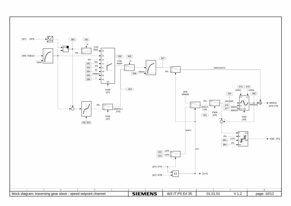
1
01.01.01 block diagram: traversing gear slave - speed setpoint channel page: 10/12I&S IT PS Erl 35 V 1.22 3 4 5 6 7 8
WNTI
332
333
-10%
+10%
375374
334 382
WNUTI[7/5]
WNSWF
WNNHG
0
1
[7/5]WGL
y=x
xy
FGR[3/7]
307
306
281
0
0%
500ms
331
0%
4000ms 4000ms
WNGG
KTA
KTB
KTI
XSD12
DPS
0
101
01
LU LL
TU
TD EN
FWN[3/4]
[9/8]
[3/7]
[3/7]
[3/7]
FHG[3/4]
100% -100%
[6/4] [7/5]
10ms
W
X1
X2
LU
LL
KP
TN
HI
[8/3]WNMA
0
10%
285
2861
1000ms
284
283
2825% -5% 30
0%
≥1
0
1
[7/5]WNPI
376
377
EN
FGR[3/7]
305
0
1
0
0%
291-302
WNPOLY[7/5]
290
304
280
WNZUSATZ
[11/2]
-
KQE383
3840%
0,5%
[4/1]
-
X
M
QU
QML
HY
0%
+
+

1
01.05.02 block diagram: traversing gear slave - monitorings page: 11/12I&S IT PS Erl 35 V 1.212 3 4 5 6 7 8
&
&
465
XNGG
XNTB[9/8]
FPP
FKGGFEGGFSGGFVERFPAR
FKOP
FKS5FES5FSS5
RESET
RESET
RESET
FKPPS
FKGERS
FKS5S
FIGNS
467
2000ms
1%
FIGNSS
46615%
RESET
455
457
2000ms
1%
45610%
MXNDSENGG
0
1
WIGG
WIMA[8/3]
0%
KTI[10/6]
4682000ms
S
RQN
S
RQN
S
RQN
S
RQN
[8/3] FEPP
[5/2]
intern
intern
[6/7]internintern
intern
[1/2][4/7]
intern
[12/8]
[12/8]
[12/8]
[4/1] [2/6] [12/1]
[4/1] [2/6] [12/1]
[4/1] [12/1]
[5/5]
[12/8]
[4/1] [2/6] [12/1]
[4/1] [2/6] [12/1][5/5]
S
RQN
X
M
HY
QU
QL
[12/1]MXND
458
460
20ms
2%
459110%
MXNGSXNGG[5/5] S
RQN
X
M
HY
QU
QL
[12/1]MXNG
RESET[12/8]
RESET[12/8]
4621%
4615%
MXN0
X
M
HY
QU
QL
4701%
46915%
FIVERSS
RQN
X
M
HY
QU
QL
FIVERS
RESET[12/8]
X
M
HY
QU
QL
[4/1] [2/6][12/1]
[4/1] [2/6]
[4/1] [2/6][12/1]
&
-
-
[5/5]
+
+
speed actual-actual monitoring
overspeed monitoring
zero speed signal
closed-loop control monitoring
current distribution monitoring
communication monitoring
fault peer to peer -coupling
fault coupling to base unit CU
fault coupling to Communication Board CB

1
01.01.01 block diagram: traversing gear slave - general page: 12/12I&S IT PS Erl 35 V 1.22 3 4 5 6 7 8
acknowledge of fault messages
send faults and alarms to base unit CU
0123
9101112131415
45678
0123
9101112131415
45678
&
1
R
FIGNSSFKGERS
FKS5SFKPPS
FIVERS
111
11111
11
MXNGMXND
000000000000
NOT828
0HFFFF
826
QUI_INNQU_IN
base unit CU faults 116-131
&8290HFFFF
827
base unit CU alarms 97-112
&[12/6]
[12/8]
[11/4]
[11/5]
[11/3][11/3][11/3]
[11/7][11/7]
fault messages:
F116: fault speed actual-actual value monitoringF117: fault coupling T300 / CUF118: fault coupling T300 /CBxF119: fault coupling peer to peerF120: fault current distribution monitoringF121: fault offset evaluation
alarms:
A97: speed setpoint-actual value differenceA98: overspeed
NOT
0T
NOT
&FWR
10s
10
QUITT
NQI_IN[12/2]
QUI_IN
RESET
[3/4]
[3/4][9/7] [11/2][11/3] [11/4][11/7]
[12/3]≥1
≥1
(fault messages of technology board T300 (F116-F120) have to acknowledge viaT300, because the faults are saved there)
factory setting
with change of parameter H832 from 0 to 1 the technology parameter (1000-1999/ d-,H-Parameter) are reset. Therefore the power is to switch off and on.After that the technology parameter are reset.
00
FVES[9/8]