Embed Size (px)
Citation preview
1
Implementing ComplexMotor Control Algorithmswith a Standard ARM®
Processor CoreBy Mike Copeland, Senior Staff Applications Engineer, Infineon Technologies
Technology In-Depth
n the real-time MCU world, cost-effective complex motor control designs have been dominated by specialized cores. In many cases
dual-core systems have been used, with the main core handling the control algorithm and a second “mini” core managing the real-time I/O and data manipulation.
n the real-time MCU world, cost-effective complex motor control designs have been dominated by specialized cores. In many cases
dual-core systems have been used, with the main core handling the control algorithm and a second “mini” core managing the real-time I/O and data manipulation.
II
To efficiently control the motor the goal is to produce stator flux that is 90 degrees out of phase with the rotor flux. The torque of the motor isthen proportional to the amplitude of the stator flux.
Several years ago I worked on an MCU-based Uninterruptable PowerSupply (UPS) project. I used the MCU with an integrated ADC and PWMmodule connected to a half bridge and a transformer to generate sinusoidal voltages. The output voltage was supposed to be a clean 110V60 Hz sinusoid independent of the load. To generate the PWM values, I first used a simple PI controller with a 110V 60 Hz reference signal. Theintention was to read the actual voltage via an ADC channel and compareit to the desired voltage, feed the error into a PI controller and use theoutput to control the PWM value. Unfortunately this did not work very well and I nearly fried the board before I had to give up.
I thought about implementing a complex non-linear control law instead ofa PI controller. Non-linear control was not one of my strengths in college,so I decided to look for an easier solution. I created a look-up table ofsinusoidal PWM values and stored it in the MCU memory. Once everyPWM interrupt, I incremented the index into the look-up table and copiedthe value into the PWM register. This produced a nice 60 Hz sinusoidalsignal, but it was very dependent on the load. To control the amplitude ofthis sinusoidal voltage, I multiplied the values from the look-up table by ascale factor before transferring them to the PWM register. Then I used asimple PI controller to control the scale factor. This worked much better.With some trigonometry (in this case just a simple sin( ) calculation via a lookup table), the simple PI controller could work just on the magnitudeof the voltage which was approximately DC.
FOC works on a similar principle. Remove the sinusoidal properties of thesystem with trigonometry, then apply simple linear PI controllers on theamplitudes.
To see how this works, let’s simplify the drawing of Figure 1(B) by usingvectors. Figure 2 is similar to Figure 1, except all of those little circles thatwere so difficult to draw are replaced by the a, b and c axes. Currentflowing through phase “a” (the winding that was drawn in dark blue inFigure 1) can be represented as a vector on the “a” axis (ia). The same istrue for phases b (the red winding) and c (the green winding).
This article describes how complex motor control algorithms can beimplemented easily and straight forward using MCUs that contain a singleCortex™-M4 core, when used in combination with smart connectedperipherals such as those found in the new Infineon XMC4000 family of products.
As an example, we will look at the equations involved in Field OrientedControl (FOC) of a Permanent Magnet Synchronous Motor (PMSM), andshow how they can be handled using the CMSIS DSP Library. The sameprinciples used in this example can be applied to other control algorithmsand other motor types. We will see how smart peripherals eliminate theneed for a second core, and describe some of the many benefits of usinga single industry standard core with the CMSIS DSP Library.
Before we look at the control algorithms and equations, it is important tounderstand the structure and operation of an PMSM.
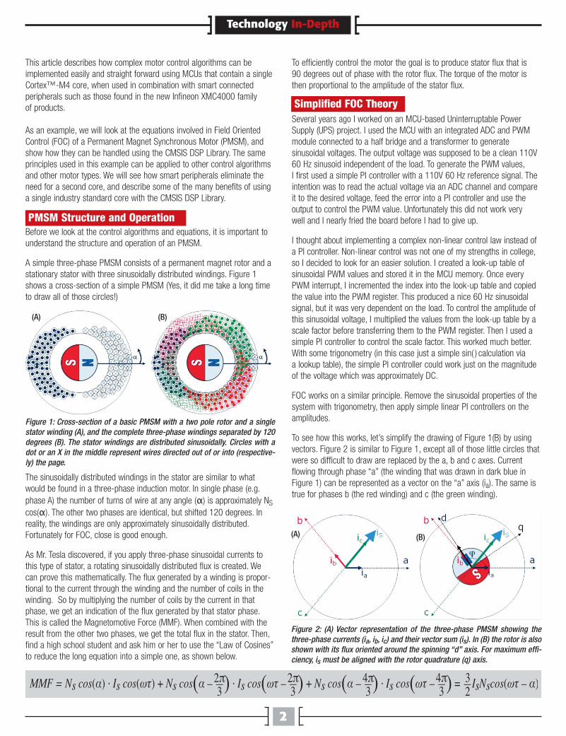
A simple three-phase PMSM consists of a permanent magnet rotor and astationary stator with three sinusoidally distributed windings. Figure 1shows a cross-section of a simple PMSM (Yes, it did me take a long timeto draw all of those circles!)
The sinusoidally distributed windings in the stator are similar to whatwould be found in a three-phase induction motor. In single phase (e.g.phase A) the number of turns of wire at any angle (α) is approximately NScos(α). The other two phases are identical, but shifted 120 degrees. Inreality, the windings are only approximately sinusoidally distributed.Fortunately for FOC, close is good enough.
As Mr. Tesla discovered, if you apply three-phase sinusoidal currents tothis type of stator, a rotating sinusoidally distributed flux is created. Wecan prove this mathematically. The flux generated by a winding is propor-tional to the current through the winding and the number of coils in thewinding. So by multiplying the number of coils by the current in thatphase, we get an indication of the flux generated by that stator phase.This is called the Magnetomotive Force (MMF). When combined with theresult from the other two phases, we get the total flux in the stator. Then,find a high school student and ask him or her to use the “Law of Cosines”to reduce the long equation into a simple one, as shown below.
2
Technology In-Depth
Simplified FOC Theory
Figure 2: (A) Vector representation of the three-phase PMSM showing thethree-phase currents (ia, ib, ic) and their vector sum (is). In (B) the rotor is alsoshown with its flux oriented around the spinning “d” axis. For maximum effi-ciency, is must be aligned with the rotor quadrature (q) axis.
PMSM Structure and Operation
Figure 1: Cross-section of a basic PMSM with a two pole rotor and a singlestator winding (A), and the complete three-phase windings separated by 120degrees (B). The stator windings are distributed sinusoidally. Circles with adot or an X in the middle represent wires directed out of or into (respective-ly) the page.
(A) (B)
(A) (B)
3
Technology In-Depth
DAVE™ 3 – Infineon’s Free Tool-Chain for XMC4000 MCUs,with DAVE™ Apps for Component-Based Programming
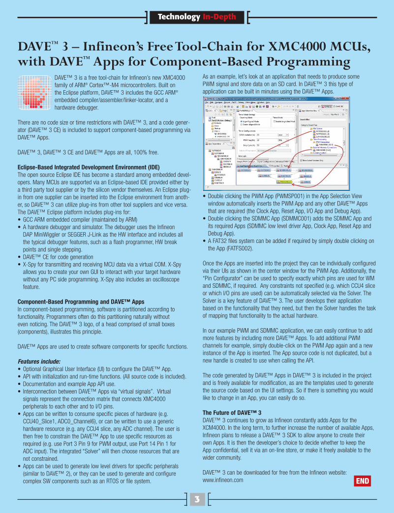
DAVE™ 3 is a free tool-chain for Infineon’s new XMC4000family of ARM® Cortex™-M4 microcontrollers. Built on the Eclipse platform, DAVE™ 3 includes the GCC ARM®
embedded compiler/assembler/linker-locator, and a hardware debugger.
There are no code size or time restrictions with DAVE™ 3, and a code gener-ator (DAVE™ 3 CE) is included to support component-based programming viaDAVE™ Apps.
DAVE™ 3, DAVE™ 3 CE and DAVE™ Apps are all, 100% free.
Eclipse-Based Integrated Development Environment (IDE)The open source Eclipse IDE has become a standard among embedded devel-opers. Many MCUs are supported via an Eclipse-based IDE provided either bya third party tool supplier or by the silicon vendor themselves. An Eclipse plug-in from one supplier can be inserted into the Eclipse environment from anoth-er, so DAVE™ 3 can utilize plug-ins from other tool suppliers and vice versa.The DAVE™ Eclipse platform includes plug-ins for:• GCC ARM embedded compiler (maintained by ARM)• A hardware debugger and simulator. The debugger uses the Infineon DAP MiniWiggler or SEGGER J-Link as the HW interface and includes all the typical debugger features, such as a flash programmer, HW breakpoints and single stepping.
• DAVE™ CE for code generation• X-Spy for transmitting and receiving MCU data via a virtual COM. X-Spy allows you to create your own GUI to interact with your target hardware without any PC side programming. X-Spy also includes an oscilloscope feature.
Component-Based Programming and DAVE™ AppsIn component-based programming, software is partitioned according to functionality. Programmers often do this partitioning naturally without even noticing. The DAVE™ 3 logo, of a head comprised of small boxes (components), illustrates this principle.
DAVE™ Apps are used to create software components for specific functions.
Features include:• Optional Graphical User Interface (UI) to configure the DAVE™ App.• API with initialization and run-time functions. (All source code is included).• Documentation and example App API use.• Interconnection between DAVE™ Apps via “virtual signals”. Virtual signals represent the connection matrix that connects XMC4000 peripherals to each other and to I/O pins.
• Apps can be written to consume specific pieces of hardware (e.g. CCU40_Slice1, ADC0_Channel6), or can be written to use a generic hardware resource (e.g. any CCU4 slice, any ADC channel). The user is then free to constrain the DAVE™ App to use specific resources as required (e.g. use Port 3 Pin 9 for PWM output, use Port 14 Pin 1 for ADC input). The integrated “Solver” will then choose resources that are not constrained.
• Apps can be used to generate low level drivers for specific peripherals (similar to DAVE™ 2), or they can be used to generate and configure complex SW components such as an RTOS or file system.
As an example, let’s look at an application that needs to produce some PWM signal and store data on an SD card. In DAVE™ 3 this type of application can be built in minutes using the DAVE™ Apps.
• Double clicking the PWM App (PWMSP001) in the App Selection View window automatically inserts the PWM App and any other DAVE™ Appsthat are required (the Clock App, Reset App, I/O App and Debug App).
• Double clicking the SDMMC App (SDMMC001) adds the SDMMC App and its required Apps (SDMMC low level driver App, Clock App, Reset App and Debug App).
• A FAT32 files system can be added if required by simply double clicking on the App (FATFS002).
Once the Apps are inserted into the project they can be individually configuredvia their UIs as shown in the center window for the PWM App. Additionally, the“Pin Configurator” can be used to specify exactly which pins are used for WMand SDMMC, if required. Any constraints not specified (e.g. which CCU4 sliceor which I/O pins are used) can be automatically selected via the Solver. TheSolver is a key feature of DAVE™ 3. The user develops their applicationbased on the functionality that they need, but then the Solver handles the taskof mapping that functionality to the actual hardware.
In our example PWM and SDMMC application, we can easily continue to addmore features by including more DAVE™ Apps. To add additional PWM channels for example, simply double-click on the PWM App again and a newinstance of the App is inserted. The App source code is not duplicated, but anew handle is created to use when calling the API.
The code generated by DAVE™ Apps in DAVE™ 3 is included in the projectand is freely available for modification, as are the templates used to generatethe source code based on the UI settings. So if there is something you wouldlike to change in an App, you can easily do so.
The Future of DAVE™ 3DAVE™ 3 continues to grow as Infineon constantly adds Apps for theXCM4000. In the long term, to further increase the number of available Apps,Infineon plans to release a DAVE™ 3 SDK to allow anyone to create their own Apps. It is then the developer’s choice to decide whether to keep the App confidential, sell it via an on-line store, or make it freely available to thewider community.
DAVE™ 3 can be downloaded for free from the Infineon website:www.infineon.com END
Clarke Transform:𝑖𝛼= 𝑖𝑎𝑖𝛽= 1 (𝑖b − 𝑖c)3Park Transform:𝑖𝑑=𝑖𝛼cos𝜑+𝑖𝛽sin𝜑𝑖𝑞=𝑖𝛽cos𝜑−𝑖𝛼sin𝜑
Once you have id and iq, they can be run through the PI controllers. One PI controller controls id to zero to ensure that the stator flux is 90 degreesfrom the rotor flux, and the other PI controller controls iq to the command-ed motor torque.
The CMSIS DSP Library contains fixed point and floating point versions ofthe Clarke and Park transforms, as well as a PID controller (a PI controlleris simply a PID controller with the derivative constant, KD, set to zero).Figure 5 shows the block diagram of a simple PI controller. The error signal e(t) is the difference between the commanded id or iq and the actual id or iq that is calculated from the measured stator currents androtor position.
Note that the output of the PI controller is a voltage, vd or vq. These arevoltages that have no real physical meaning. You cannot directly convert vdand vq into duty cycles for a PWM unit, so more trigonometry is required.
There are many ways to convert vd and vq into duty cycles for a three-phase inverter. We will look at just one method called Space VectorModulation (SVM). An entire article could easily be devoted to the theory ofSVM (indeed, I wrote one several years ago!), but for the sake of brevitywe will focus on the basics.
vd and vq are referenced to the rotor position. We need to project thesevoltages onto actual voltage vectors that can be produced by a three-
phase inverter.
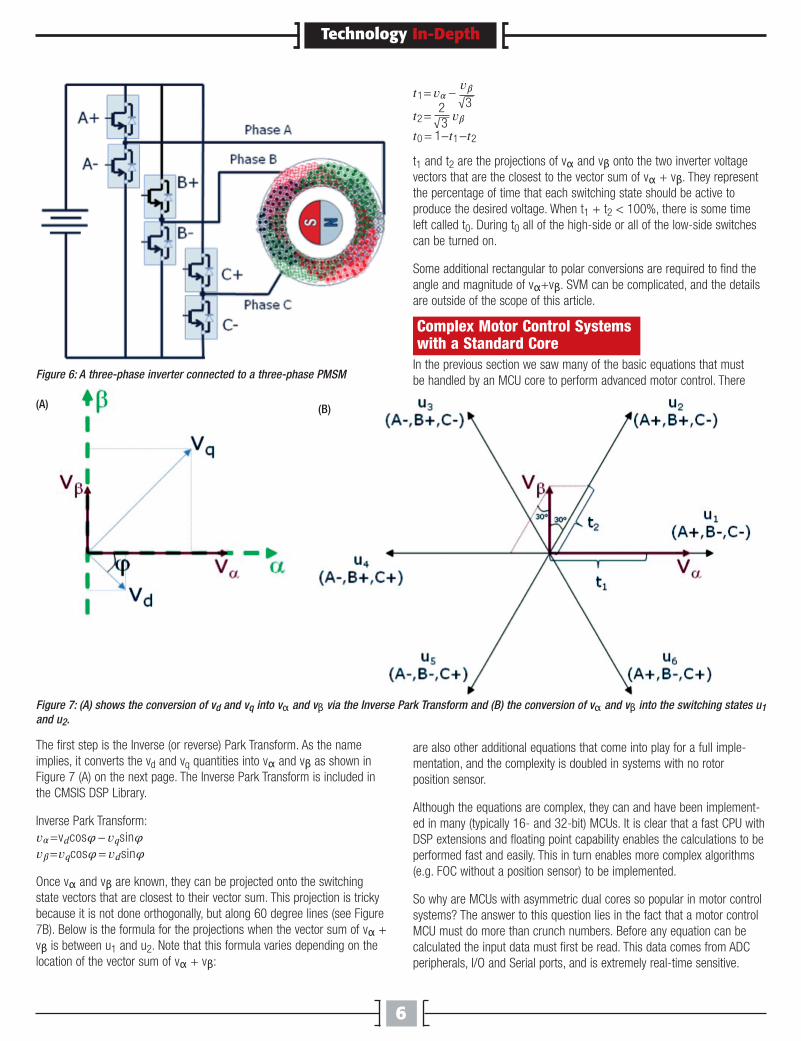
Figure 6 shows a three-phase inverter. Thereare six non-zero voltages that can be producedby the inverter. Each vector is produced byturning on one high-side switch and two low-side switches, or two high-side switches andone low-side switch. These voltage vectors andthe inverter state that is used to reach them areshown in Figure 7B.
We will use a two step process to project vdand vq onto inverter voltage vectors.
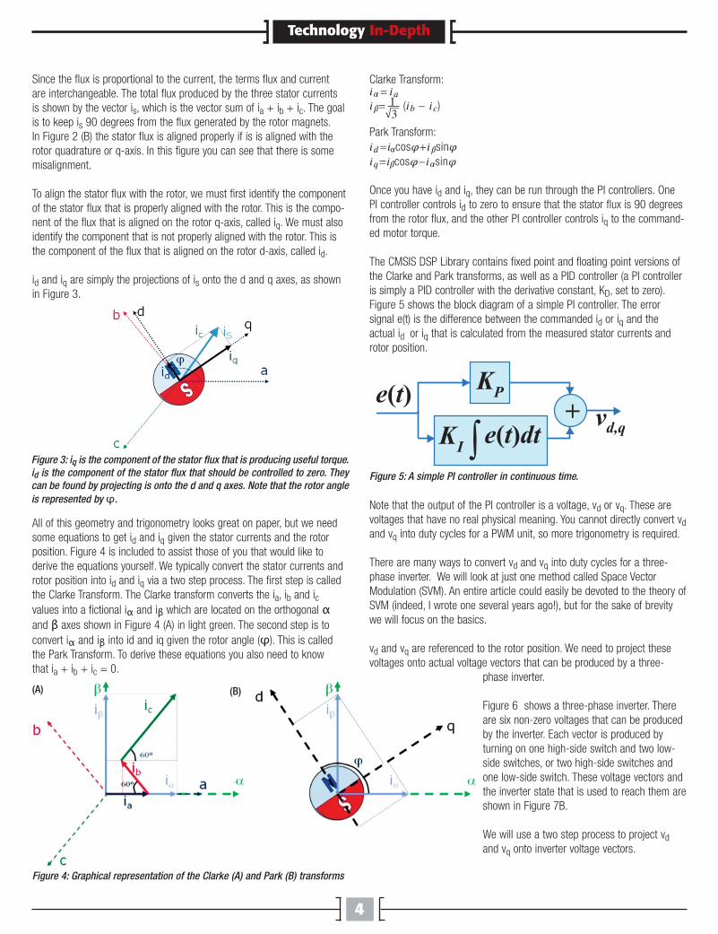
Since the flux is proportional to the current, the terms flux and current are interchangeable. The total flux produced by the three stator currents is shown by the vector is, which is the vector sum of ia + ib + ic. The goalis to keep is 90 degrees from the flux generated by the rotor magnets. In Figure 2 (B) the stator flux is aligned properly if is is aligned with therotor quadrature or q-axis. In this figure you can see that there is somemisalignment.
To align the stator flux with the rotor, we must first identify the componentof the stator flux that is properly aligned with the rotor. This is the compo-nent of the flux that is aligned on the rotor q-axis, called iq. We must alsoidentify the component that is not properly aligned with the rotor. This isthe component of the flux that is aligned on the rotor d-axis, called id.
id and iq are simply the projections of is onto the d and q axes, as shownin Figure 3.
All of this geometry and trigonometry looks great on paper, but we needsome equations to get id and iq given the stator currents and the rotorposition. Figure 4 is included to assist those of you that would like toderive the equations yourself. We typically convert the stator currents androtor position into id and iq via a two step process. The first step is calledthe Clarke Transform. The Clarke transform converts the ia, ib and icvalues into a fictional iα and iβ which are located on the orthogonal αand β axes shown in Figure 4 (A) in light green. The second step is toconvert iα and iβ into id and iq given the rotor angle (φ). This is calledthe Park Transform. To derive these equations you also need to know that ia + ib + ic = 0.
4
Technology In-Depth
Figure 4: Graphical representation of the Clarke (A) and Park (B) transforms
Figure 5: A simple PI controller in continuous time.
Figure 3: iq is the component of the stator flux that is producing useful torque.id is the component of the stator flux that should be controlled to zero. Theycan be found by projecting is onto the d and q axes. Note that the rotor angleis represented by φ.
(A) (B)
5
Technology In-Depth
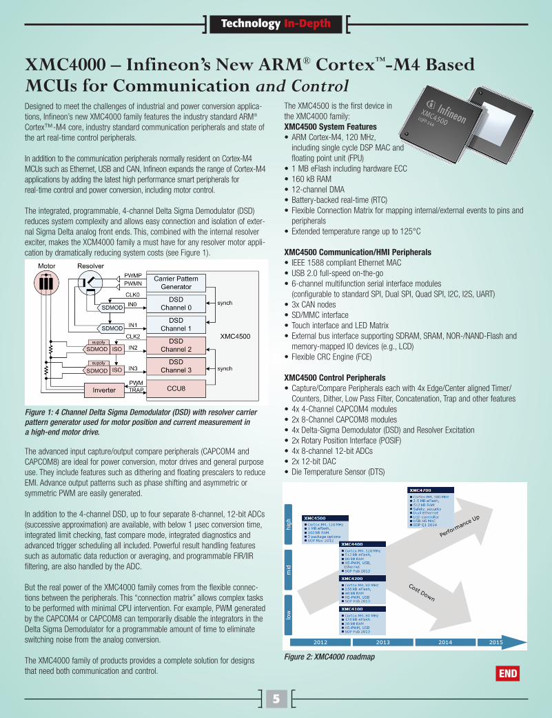
XMC4000 – Infineon’s New ARM® Cortex™-M4 BasedMCUs for Communication and ControlDesigned to meet the challenges of industrial and power conversion applica-tions, Infineon’s new XMC4000 family features the industry standard ARM®
Cortex™-M4 core, industry standard communication peripherals and state ofthe art real-time control peripherals.
In addition to the communication peripherals normally resident on Cortex-M4MCUs such as Ethernet, USB and CAN, Infineon expands the range of Cortex-M4applications by adding the latest high performance smart peripherals for real-time control and power conversion, including motor control.
The integrated, programmable, 4-channel Delta Sigma Demodulator (DSD)reduces system complexity and allows easy connection and isolation of exter-nal Sigma Delta analog front ends. This, combined with the internal resolverexciter, makes the XCM4000 family a must have for any resolver motor appli-cation by dramatically reducing system costs (see Figure 1).
The advanced input capture/output compare peripherals (CAPCOM4 and CAPCOM8) are ideal for power conversion, motor drives and general purposeuse. They include features such as dithering and floating prescalers to reduceEMI. Advance output patterns such as phase shifting and asymmetric or symmetric PWM are easily generated.
In addition to the 4-channel DSD, up to four separate 8-channel, 12-bit ADCs(successive approximation) are available, with below 1 µsec conversion time,integrated limit checking, fast compare mode, integrated diagnostics andadvanced trigger scheduling all included. Powerful result handling featuressuch as automatic data reduction or averaging, and programmable FIR/IIR filtering, are also handled by the ADC.
But the real power of the XMC4000 family comes from the flexible connec-tions between the peripherals. This “connection matrix” allows complex tasksto be performed with minimal CPU intervention. For example, PWM generatedby the CAPCOM4 or CAPCOM8 can temporarily disable the integrators in theDelta Sigma Demodulator for a programmable amount of time to eliminateswitching noise from the analog conversion.
The XMC4000 family of products provides a complete solution for designsthat need both communication and control.
The XMC4500 is the first device in the XMC4000 family: XMC4500 System Features• ARM Cortex-M4, 120 MHz, including single cycle DSP MAC and floating point unit (FPU)
• 1 MB eFlash including hardware ECC• 160 kB RAM• 12-channel DMA • Battery-backed real-time (RTC)• Flexible Connection Matrix for mapping internal/external events to pins and peripherals
• Extended temperature range up to 125°C
XMC4500 Communication/HMI Peripherals• IEEE 1588 compliant Ethernet MAC• USB 2.0 full-speed on-the-go • 6-channel multifunction serial interface modules (configurable to standard SPI, Dual SPI, Quad SPI, I2C, I2S, UART)
• 3x CAN nodes • SD/MMC interface• Touch interface and LED Matrix • External bus interface supporting SDRAM, SRAM, NOR-/NAND-Flash and memory-mapped IO devices (e.g., LCD)
• Flexible CRC Engine (FCE)
XMC4500 Control Peripherals• Capture/Compare Peripherals each with 4x Edge/Center aligned Timer/ Counters, Dither, Low Pass Filter, Concatenation, Trap and other features
• 4x 4-Channel CAPCOM4 modules• 2x 8-Channel CAPCOM8 modules• 4x Delta-Sigma Demodulator (DSD) and Resolver Excitation• 2x Rotary Position Interface (POSIF)• 4x 8-channel 12-bit ADCs• 2x 12-bit DAC• Die Temperature Sensor (DTS)
Figure 1: 4 Channel Delta Sigma Demodulator (DSD) with resolver carrier pattern generator used for motor position and current measurement in a high-end motor drive.
Figure 2: XMC4000 roadmap
END
𝑡1=𝑣𝛼 −𝑣𝛽3
𝑡2=2 𝑣𝛽3
𝑡0= 1−𝑡1−𝑡2
t1 and t2 are the projections of vα and vβ onto the two inverter voltagevectors that are the closest to the vector sum of vα + vβ. They representthe percentage of time that each switching state should be active to produce the desired voltage. When t1 + t2 < 100%, there is some timeleft called t0. During t0 all of the high-side or all of the low-side switchescan be turned on.
Some additional rectangular to polar conversions are required to find theangle and magnitude of vα+vβ. SVM can be complicated, and the detailsare outside of the scope of this article.
In the previous section we saw many of the basic equations that must be handled by an MCU core to perform advanced motor control. There
are also other additional equations that come into play for a full imple-mentation, and the complexity is doubled in systems with no rotor position sensor.
Although the equations are complex, they can and have been implement-ed in many (typically 16- and 32-bit) MCUs. It is clear that a fast CPU withDSP extensions and floating point capability enables the calculations to beperformed fast and easily. This in turn enables more complex algorithms(e.g. FOC without a position sensor) to be implemented.
So why are MCUs with asymmetric dual cores so popular in motor controlsystems? The answer to this question lies in the fact that a motor controlMCU must do more than crunch numbers. Before any equation can becalculated the input data must first be read. This data comes from ADCperipherals, I/O and Serial ports, and is extremely real-time sensitive.
6
Technology In-Depth
The first step is the Inverse (or reverse) Park Transform. As the nameimplies, it converts the vd and vq quantities into vα and vβ as shown inFigure 7 (A) on the next page. The Inverse Park Transform is included inthe CMSIS DSP Library.
Inverse Park Transform:𝑣𝛼=v𝑑cos𝜑−𝑣𝑞sin𝜑𝑣𝛽=𝑣𝑞cos𝜑=𝑣𝑑sin𝜑
Once vα and vβ are known, they can be projected onto the switchingstate vectors that are closest to their vector sum. This projection is trickybecause it is not done orthogonally, but along 60 degree lines (see Figure7B). Below is the formula for the projections when the vector sum of vα +vβ is between u1 and u2. Note that this formula varies depending on thelocation of the vector sum of vα + vβ:
Figure 6: A three-phase inverter connected to a three-phase PMSM
Figure 7: (A) shows the conversion of vd and vq into vα and vβ via the Inverse Park Transform and (B) the conversion of vα and vβ into the switching states u1and u2.
Complex Motor Control Systems with a Standard Core
(A) (B)
7
Technology In-Depth
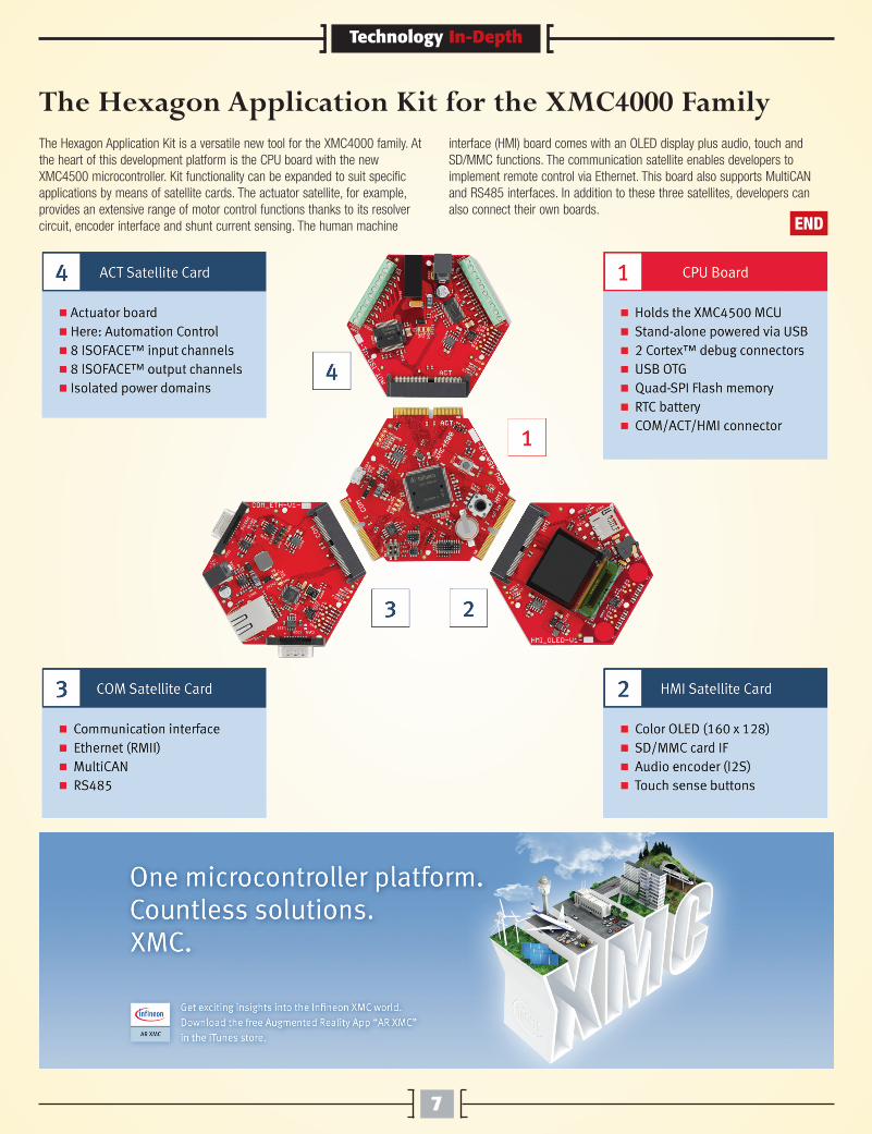
The Hexagon Application Kit for the XMC4000 FamilyThe Hexagon Application Kit is a versatile new tool for the XMC4000 family. Atthe heart of this development platform is the CPU board with the newXMC4500 microcontroller. Kit functionality can be expanded to suit specificapplications by means of satellite cards. The actuator satellite, for example,provides an extensive range of motor control functions thanks to its resolvercircuit, encoder interface and shunt current sensing. The human machine
interface (HMI) board comes with an OLED display plus audio, touch andSD/MMC functions. The communication satellite enables developers to implement remote control via Ethernet. This board also supports MultiCAN and RS485 interfaces. In addition to these three satellites, developers can also connect their own boards.
END
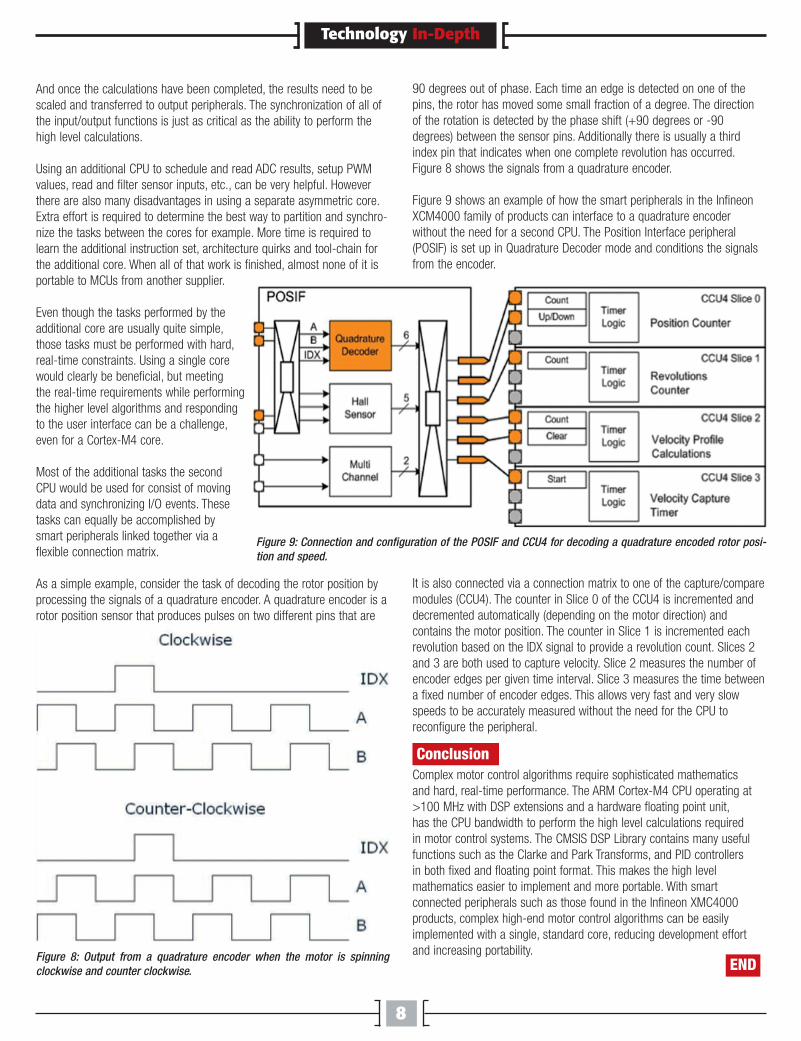
90 degrees out of phase. Each time an edge is detected on one of thepins, the rotor has moved some small fraction of a degree. The directionof the rotation is detected by the phase shift (+90 degrees or -90degrees) between the sensor pins. Additionally there is usually a thirdindex pin that indicates when one complete revolution has occurred.Figure 8 shows the signals from a quadrature encoder.
Figure 9 shows an example of how the smart peripherals in the InfineonXCM4000 family of products can interface to a quadrature encoder without the need for a second CPU. The Position Interface peripheral(POSIF) is set up in Quadrature Decoder mode and conditions the signalsfrom the encoder.
It is also connected via a connection matrix to one of the capture/comparemodules (CCU4). The counter in Slice 0 of the CCU4 is incremented anddecremented automatically (depending on the motor direction) and contains the motor position. The counter in Slice 1 is incremented eachrevolution based on the IDX signal to provide a revolution count. Slices 2and 3 are both used to capture velocity. Slice 2 measures the number ofencoder edges per given time interval. Slice 3 measures the time betweena fixed number of encoder edges. This allows very fast and very slowspeeds to be accurately measured without the need for the CPU to reconfigure the peripheral.
Complex motor control algorithms require sophisticated mathematics and hard, real-time performance. The ARM Cortex-M4 CPU operating at>100 MHz with DSP extensions and a hardware floating point unit, has the CPU bandwidth to perform the high level calculations required in motor control systems. The CMSIS DSP Library contains many usefulfunctions such as the Clarke and Park Transforms, and PID controllers in both fixed and floating point format. This makes the high level mathematics easier to implement and more portable. With smart connected peripherals such as those found in the Infineon XMC4000products, complex high-end motor control algorithms can be easily implemented with a single, standard core, reducing development effortand increasing portability.
8
Technology In-Depth
And once the calculations have been completed, the results need to bescaled and transferred to output peripherals. The synchronization of all ofthe input/output functions is just as critical as the ability to perform thehigh level calculations.
Using an additional CPU to schedule and read ADC results, setup PWMvalues, read and filter sensor inputs, etc., can be very helpful. Howeverthere are also many disadvantages in using a separate asymmetric core.Extra effort is required to determine the best way to partition and synchro-nize the tasks between the cores for example. More time is required tolearn the additional instruction set, architecture quirks and tool-chain forthe additional core. When all of that work is finished, almost none of it isportable to MCUs from another supplier.
Even though the tasks performed by theadditional core are usually quite simple,those tasks must be performed with hard,real-time constraints. Using a single corewould clearly be beneficial, but meeting the real-time requirements while performingthe higher level algorithms and respondingto the user interface can be a challenge,even for a Cortex-M4 core.
Most of the additional tasks the second CPU would be used for consist of movingdata and synchronizing I/O events. Thesetasks can equally be accomplished by smart peripherals linked together via a flexible connection matrix.
As a simple example, consider the task of decoding the rotor position byprocessing the signals of a quadrature encoder. A quadrature encoder is arotor position sensor that produces pulses on two different pins that are
Figure 8: Output from a quadrature encoder when the motor is spinningclockwise and counter clockwise.
Figure 9: Connection and configuration of the POSIF and CCU4 for decoding a quadrature encoded rotor posi-tion and speed.
Conclusion
END