Embed Size (px)
Citation preview
page 1 of 60
Chemistry-HYBRID-pump
RC 6
Instructions for useTechnology for Vacuum Systems
page 2 of 60
Dear customer,
Your VACUUBRAND pumps are designed to provide you with many years of trouble-free service with optimal performance. Through our long expe-rience in design, construction and operation of vacuum pumps, combined with the latest developments in material and manufacturing technology, we have accumulated a wealth of application and safety insights that we want to share with you. Please read these instructions for use before the initial operation of your pump.
Our quality maxim is the ”zero fault principle”:Every pump, before leaving our factory, is tested intensively, including an endurance run of 60 hours. Any faults, even those which occur rarely, are identified and can be eliminated immediately.After completion of the endurance run, every pump is tested, and must achieve specifications before shipment.We are committed to providing our customers only pumps that meet this high quality standard.While our pumps cannot eliminate all of your work, we design, manufac-ture and test them to ensure that they will be an effective and trouble-free tool to assist you in that work.
Yours,VACUUBRAND GMBH + CO KG
After sales service: Contact your local dealer or call +49 9342 808-5500.
Trademark index:VACUU•LAN® (US-Reg.No 3,704,401), VACUU•BUS®, VACUU•CONTROL®, Peltronic®, VARIO® (US-Reg.No 3,833,788), VACUUBRAND® (US-Reg.No 3,733,388) and also the shown company logos are registered trademarks of VACUUBRAND GMBH + CO KG in Germany and/or other countries.
page 3 of 60
ContentsSafety information! ............................................................. 5
Important information! ......................................................................... 5General information ............................................................................. 7Intended use........................................................................................ 7Setting up and installing the equipment .............................................. 9Ambient conditions .............................................................................11Operating conditions ......................................................................... 12Safety during operation ..................................................................... 13Maintenance and repair..................................................................... 16
Technical data ................................................................... 19 Gas inlet temperatures ..................................................................... 21 Wetted parts ..................................................................................... 21 Abbreviations .................................................................................... 21 Pump parts ....................................................................................... 22
Use and operation ............................................................ 23Initial operation / Pouring in the pump oil .......................................... 24Installing a pump in a vacuum system .............................................. 25During operation ................................................................................ 27Important notes regarding the use of gas ballast .............................. 30Operating the pump with condensate in the catchpots ..................... 32Pumping chemically aggressive or toxic gases and vapors .............. 33Shutdown .......................................................................................... 34
Oil change ......................................................................... 35Oil change procedure ........................................................................ 36Notes on choosing the appropriate oil for the application ................. 37
Accessories ...................................................................... 39Troubleshooting ............................................................... 41Replacing diaphragms and valves.................................. 44
Cleaning and inspecting the diaphragm pump heads ...................... 46 Replacing the diaphragm ................................................................. 48 Assembling the pump heads ............................................................ 50 Assembling the connecting hose ...................................................... 51 Checking the operability of the diaphragm pump ............................. 51 Replacing the filter element in the oil mist filter ................................ 52 Inspecting the safety pop valve ........................................................ 52
page 4 of 60
Repair - Maintenance - Return - Calibration ................... 53Warranty ............................................................................ 55Health and safety clearance form ................................... 56EC Declaration of Conformity of the Machinery ........... 57China RoHS ....................................................................... 58
page 5 of 60
Safety information!Important information!
+Keep this manual complete and accessible to per-sonnel at all times!
+Read this manual carefully before installing or op-erating the equipment. Observe the instructions contained in this manual.
+Do not modify the equipment without authoriza-tion.
This manual is an integral part of the equipment de-scribed therein. It describes the safe and proper use of the vacuum pump. Make operating personnel aware of dangers arising from the pump and the pumped substances. VACUUBRAND disclaims any liability for inappropri-ate use of these pumps and for damage from failure to follow instructions contained in this manual.
This manual is only to be used and distributed in its com-plete and original form. It is strictly the users’ responsibility to check carefully the validity of this manual with respect to his product. Manual-no.: 997829 / 07/07/2017
The following signal word panels and safety symbols are used throughout this manual:
This is the safety alert symbol. It is used to alert you to po-tential personal injury hazards. Obey all safety messages that follow this symbol to avoid possible injury and death.
NOTICE
page 6 of 60
➨ DANGER indicates a hazardous situation which, if not avoided, will result in death or serious injury.
+ WARNING indicates a hazardous situation which, if not avoided, could result in death or serious injury.
• CAUTION indicates a hazardous situation which, if not
avoided, could result in minor or moderate injury. NOTICE is used to address practices not related to
personal injury.
Caution! Hot surface! Disconnect equipment from AC power.
NOTICE
Formatting used in this manual:Note: The signal word panels in all sections of this manual always refer to all paragraphs of the same format (➨ / + / • / plain text) following each signal word panel.
The document ”Safety information for vacuum equipment” is part of this manual! Read the ”Safety information for vacuum equipment” and observe the instructions contained therein!
page 7 of 60
General information
Remove all packing material from the packing box. Re-move the product from its packing-box and retain all pack-aging until the equipment is inspected and tested. Re-move the protective caps from the inlet and outlet ports and retain for future use. Inspect the equipment promptly and carefully.If the equipment is damaged, notify the supplier and the carrier in writing within three days. Retain all packing ma-terial for inspection. State the item number of the product together with the order number and the supplier’s invoice number. Failure to check and give notice of damage will void any and all warranty claims for those deficiencies.Replace the protective caps, if the equipment is not used immediately. Store the equipment in dry and non-corrosive conditions (see also “Technical data”, pg. 19).
+ Do not use any damaged equipment.
• Check the pump‘s oil level. • The pump is delivered without oil filling. Fill with oil
before operating the pump, see section ”Use and operation”, pg. 23.
• Aging of the oil (as indicated by darker color compared to new oil, strange odor of the oil, particles in the oil, or contamination) necessitates an oil change.
• Use the handle when moving the pump.
Intended use+ Do not use the pump or any system parts on humans
or animals.
+ Ensure that the individual components are only con-nected, combined and operated according to their de-sign and as indicated in the instructions for use.
Use only original manufacturer’s spare parts and
NOTICE
page 8 of 60
accessories. Otherwise the safety and performance of the equipment, as well as the electromagnetic com-patibility of the equipment might be reduced.
The CE mark may be voided if not using original man-ufacturer’s spare parts.
+ Comply with all notes on correct vacuum and electri-cal connections; see section “Use and operation”, pg. 23.
+ Do not use the pump to generate pressure.
+The pumps are designed for ambient temperatures during operation between +54°F and +104°F (+12°C and +40°C). Periodically check maximum tempera-tures if installing the pump in a cabinet or a housing. Make sure ventilation is adequate to maintain recom-mended operating temperature. Install an external au-tomatic ventilation system if necessary. If pumping hot process gases, make sure that the maximum permitted gas inlet temperature is not exceeded. The maximum permitted gas inlet temperature depends on several parameters like inlet pressure and ambient tempera-ture (see “Technical data”, pg. 19).
+Particles and dust must not enter the pump.+Do not pump liquids.
• Ensure that the pump is chemically resistant to the pumped substances prior to operation.
Use the equipment only as intended, that is, for genera-tion of vacuum in vessels designed for that purpose. Any other use will automatically invalidate all warranty and li-ability claims. Remain aware of safety and risks.
NOTICE
page 9 of 60
Setting up and installing the equipment➨ Equipment must be connected only to a suitable elec-
trical supply and a suitable ground point. As such, the plug must be plugged into an outlet that is properly grounded. Failure to connect the motor to ground may result in deadly electrical shock.
The supply cable may be fitted with a molded Europe-an IEC plug or a plug suitable for your local electrical supply. The cable contains wires color coded as fol-lows: green or green and yellow: ground; blue or white: neutral; brown or black: hot.
+ Due to the high compression ratio, the pump may gen-erate overpressure at the outlet. Check pressure com-patibility with system components (e.g., exhaust pipe-line or exhaust valve) at the outlet.
+ Do not permit any uncontrolled pressurizing. Make sure that the exhaust tubing cannot become blocked. If there is an exhaust isolation valve, make sure that you cannot operate the equipment with the valve closed to avoid a risk of bursting!
+ Keep the electrical power cord away from heated sur-faces.
• Provide a firm, level platform for the equipment. Check that the system which you are going to evacuate is mechanically stable. Check that all fittings are secure. Ensure a stable position of the pump without any me-chanical contact other than the pump feet.
• Comply with maximum permissible pressures at in-let and outlet and with maximum permissible pres-sure differences between inlet and outlet. See section “Technical data”, pg. 19. Do not operate the pump with overpressure at the inlet.
• Avoid overpressure of more than 17.5 psi absolute (1.2 bar absolute) in the event that gas or inert gas is con-
page 10 of 60
nected to the pump, to the gas ballast or to a venting valve.
• Note: Flexible elements will shrink when evacuated.• Connect hoses gas tight at inlet and outlet of the pump.• Ensure that no foreign objects can be drawn into the
pump.• Check the power source and the pump’s rating plate
to be sure that the power source and the equipment match in voltage, phase, and frequency.
• Use only oil of the recommended type. Other oils or operating fluids may cause damage of the pump or danger.
Use special oils (see “Oil change”, pg. 35) for the rotary vane pump, if, e.g.,
- acid vapors are pumped. - extremely high aging stability is required. - oxygen or other strong oxidizing agents are pumped.
• Take adequate precautions when handling pump flu-ids, lubricants, and solvents. Use appropriate protec-tive clothing, safety goggles and protective gloves to avoid excessive contact with the skin and possible skin irritations (including dermatitis). Do not inhale or swallow! Ensure that the pump location is well venti-lated and that possible toxic effects of certain vapors are avoided. Maintain adequate levels of hygiene and cleanliness.
• Comply with all relevant statutory requirements and regulations concerning the handling, storage and dis-posal of oil.
Note: Do not allow oils to enter the drainage system or other bodies of water. Spillage can cause accidents (slip hazard)!
Make sure ventilation is adequate to maintain recommend-ed operating temperature. Keep a minimum distance of 2 in (5 cm) between the cooling fan and surrounding items
NOTICE
page 11 of 60
(e.g., housing, walls, etc.), or else install an external au-tomatic ventilation system. Check fan regularly for dust/dirt. Clean fan guard if necessary to avoid a reduction of ventilation.
The On/Off switch is located at the side of the terminal box.
Use only hoses at the inlet and outlet of the pump with an inner diameter at least as large as the diameter of the pump’s connections (to avoid overpressure at the outlet, and reduction of pumping speed at the inlet).
Allow the equipment to equilibrate to ambient temperature if you bring it from cold environment into a room prior to operation. Notice if there is water condensation on cold surfaces.
Comply with all applicable and relevant safety require-ments (regulations and guidelines). Implement the re-quired actions and adopt suitable safety measures.
Ambient conditions
➨ Do not reach for this product if it has fallen into liquid. There is a risk of deadly electrical shock. Unplug the system immediately.
+ Do not use this product in an area where it can fall or be pulled into water or other liquids.
• Adopt suitable measures in case of differences from recommended conditions, e.g., using the equipment outdoors, installation in higher altitudes, conductive pollution or external condensation on the pump.
• Do not operate this product near flames.
page 12 of 60
To the best of our knowledge the equipment is in com-pliance with the requirements of the applicable EC-direc-tives and harmonized standards (see ”Declaration of Con-formity”) with regard to design, type and model. Directive EN 61010-1 gives in detail the conditions under which the equipment can be operated safely (see also IP degree of protection, “Technical data”, pg. 19).
Operating conditions➨ These pumps are not approved for operation in po-
tentially explosive atmospheres. Do not operate the pumps in potentially explosive atmospheres.
➨ These pumps are not approved for the pumping of po-tentially explosive atmospheres. Do not pump poten-tially explosive atmospheres.
➨ The pumps are not suitable to pump any of the sub-stances listed below.
Do not pump:- unstable substances - substances which react explosively under impact
(mechanical stress) without air- substances which react explosively when being ex-
posed to elevated temperatures without air,- self inflammable substances, - substances which are inflammable without air- explosive substances.
➨The pumps are not approved for operation below ground. Do not operate the pump below ground.
• Do not pump substances which may form depos-its inside the pump. The pumps are not suitable for pumping substances which may form deposits inside the pump. Deposits and condensate in the pump may lead to increased temperatures even to the point of exceeding the maximum permitted temperatures. De-posits may cause seizing of the pump unit.
NOTICE
page 13 of 60
• Check the inlet and outlet of the pump and its oil condi-tion, if there is a danger of forming deposits inside the pump, e.g., in the pump unit of the rotary vane pump or in the pump chamber of the diaphragm pump. Inspect the pump regularly and clean if necessary.
• Install a cold trap in front of the pump if pumping ag-gressive or corrosive gases or vapors.
• Consider interactions and chemical reactions of the pumped media. Ensure that the materials of the pump’s wetted parts are compatible with the pumped substances, see section “Technical data”, pg. 19.
When changing the substances pumped, we recom-mend purging the pump with air or inert gas prior to changing the pumped media. Purging the pump will pump out residues and it will reduce the possibility of reactions of the pumped substances with each other and with the pump’s materials.
Safety during operation
➨ Adopt suitable measures to prevent the release of dan-gerous, toxic, explosive, corrosive, noxious or pollut-ing fluids, vapors and gases. To prevent any emission of such substances from the pump outlet, install an appropriate collecting and disposal system and take protective action for pump and environment.
➨ You must take suitable precautions to prevent any for-mation of explosive mixtures in the expansion cham-ber, in the oil reservoir, in the pump chamber of the diaphragm pump, or at the outlet of the pump. In case, e.g., of a diaphragm failure, mechanically generated sparks, hot surfaces or static electricity may ignite these mixtures. Use inert gas for gas ballast or vent-ing, if necessary.
➨ Drain appropriately or otherwise remove any poten-
page 14 of 60
tially explosive mixtures at the outlet of the pump, or dilute them to non-explosive concentrations.
➨Never operate this pump if it has a damaged cord or plug.
+ If the pump is not working properly, has been dropped or has fallen into water, contact your pump service pro-vider.
+ Prevent any part of the human body from coming into contact with vacuum.
+Always provide a free and pressureless exhaust out-let. Make sure that the exhaust tubing cannot become blocked. Do not exceed an pressure of 16 psi (1.1 bar) in the exhaust tubing.
+ Comply with applicable regulations when disposing of chemicals. Take into consideration that chemicals may be contaminated. Take adequate precautions to pro-tect people from the effects of dangerous substances (chemicals, oil mist, thermal decomposition products of fluoroelastomers). Use appropriate protective cloth-ing and safety goggles.
+Even if the pumped medium is only air or a pure gas, the discharge from rotary vane pumps will contain small quantities of oil vapor and petroleum fractions. These substances are particularly contaminating in closed spaces or in case of insufficient ventilation.
The discharge from the pump invariably contains the pumped gases or vapors! Connect a hose to the pump outlet to dispose of the exhaust gases.
Prevent any dangerous reactions with oil or oil vapors and the formation of impermissible or dangerous emis-sions.
+ Failure of the pump (e.g., due to power interruption), failure of connected components or of parts of the sup-ply, or a change of parameters must not be allowed to lead to a dangerous situation under any circumstances.
page 15 of 60
In case of a leak in the manifold or at the shaft seal of the rotary vane pump, or in case of a diaphragm crack of the diaphragm pump, pumped substances might be released into the environment or into the pump hous-ing or motor.
Especially comply with notes on use and operation and maintenance.
+ The residual leak rate of the equipment might render possible an exchange of gas, albeit extremely slight, between the environment and the vacuum system.
Adopt suitable measures to prevent contamination of the pumped substances or the environment.
• Ensure that no parts of your clothing, hair or fingers can be caught or drawn in at the inlet of the pump. Never insert fingers or drop any other object into the inlet or outlet.
• Pumping at high inlet pressure may lead to overpres-sure at the gas ballast valve. Pumped gases or con-densate might be expelled if the valve is open. If an in-ert gas supply is connected to the gas ballast, ensure that its inlet pipeline is not contaminated.
• Check oil level of the rotary vane pump (through sight glass) every time before starting the pump.
• Check the pump’s oil level and the condition of the oil on a regular basis.
• Pay attention to the safety symbol ”hot surfaces” on the equipment. Hot parts may cause burns if touched. Adopt suitable measures to prevent any danger aris-ing from hot surfaces or electric sparks. Ensure that hot surfaces of the pump do not cause burns. Provide a suitable contact guard if necessary.
• A power failure or switching off the pump may cause accidental ventilation of the pump or the vacuum sys-tem, if the manual gas ballast valve of the rotary vane
page 16 of 60
pump is open. If this constitutes a potential source of danger, take appropriate safety measures, e.g., install a solenoid operated gas ballast valve.
Prevent the backpressure of gases and the backflow of condensates at the outlet.
Important notes on working with condensable vapors:Allow the pump to attain its operating temperature before pumping condensable vapors. Keep the vapor inlet pres-sure below the permitted maximum (see ”Technical data”, pg. 19).
Open the gas ballast valve in case of pumping significant amounts of vapor.Provide appropriate protective measures to allow for the possibility of failure and malfunction. The protective mea-sures must also allow for the requirements of the respec-tive application.
In case of overload, the motor is shut down by a self-hold thermal cutout in the winding.Note: Only manual reset is possible. Switch off the pump and disconnect from the power source. Identify and elimi-nate the cause of failure. Wait approx. five minutes before restarting the pump.
Maintenance and repair
In order to comply with laws (occupational, health and safety regulations, safety at work law and regulations for environmental protection) vacuum pumps, components and measuring instruments can only be returned when certain procedures (see section ““Repair - Maintenance - Return - Calibration”, pg. 53”, pg. 53) are followed.
Take advantage of our service seminars, which put special focus on the maintenance and repair of vacuum pumps.
NOTICE
NOTICE
page 17 of 60
For details and for the online ”Instructions for repair” man-ual see www.vacuubrand.com. In normal use, the lifetime of the diaphragms and valves is typically 15,000 operating hours. Bearings have a typi-cal durability of 40000 h. Motor capacitors have a typi-cal durability in the range of 10000 to 40000 h depending strongly on operation conditions, including ambient tem-perature, humidity or load.
➨ Ensure that the pump cannot be operated acciden-tally. Never operate the pump if covers or other parts of the pump are disassembled.
➨ Switch off the pump. Disconnect the electrical
power cord and wait five seconds before starting maintenance to allow the capacitors to discharge.
➨ Note: The pump may be contaminated with process chemicals, which have been pumped during operation. Ensure that the pump is completely decontaminated before maintenance commences. Avoid the release of pollutants.
+Take adequate precautions to protect people from the effects (e.g., in case of inhalation or skin contact) of dangerous substances if contamination has occurred. Use appropriate protective clothing, safety goggles and protective gloves.
+Wear parts have to be replaced regularly. +Never operate a defective or damaged pump.
+ Check every motor capacitor regularly by measuring its capacity and estimating its time in operation. Re-place old capacitors early enough to prevent a failure in operation. If an old motor capacitor fails, the capaci-tor may get hot. It may even melt or emit a flame, which could be dangerous for persons and equipment in the vicinity. The capacitors have to be replaced by an
page 18 of 60
electrician.
+ Vent the pump before starting maintenance. Isolate the pump and other components from the vacuum system. Allow sufficient cooling of the pump. Drain condensate, if applicable.
Ensure that maintenance is done only by suitably trained and supervised technicians. Ensure that the maintenance technician is familiar with the safety procedures which re-late to the products processed by the pumping system.
NOTICE
page 19 of 60
Technical data
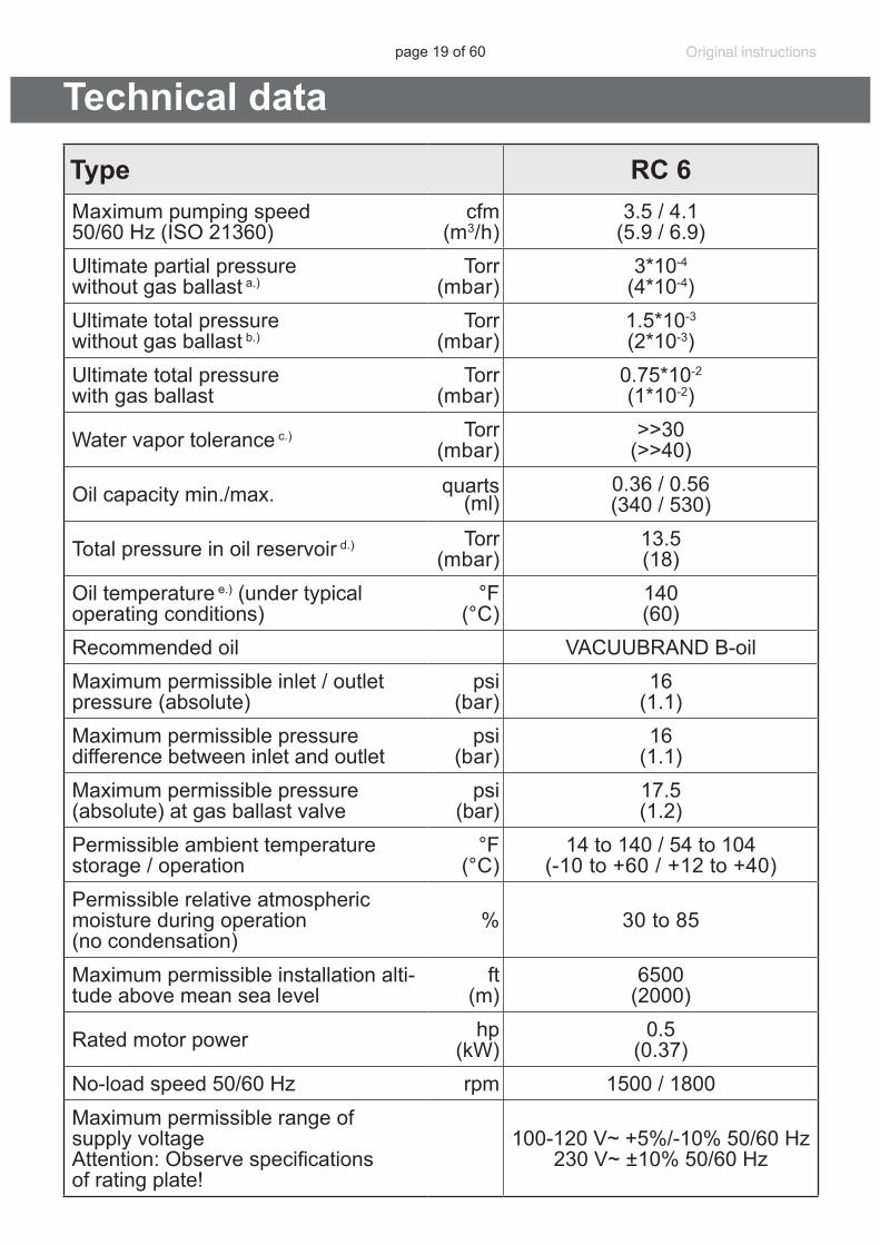
Type RC 6Maximum pumping speed50/60 Hz (ISO 21360)
cfm(m3/h)
3.5 / 4.1(5.9 / 6.9)
Ultimate partial pressure without gas ballast a.)
Torr(mbar)
3*10-4
(4*10-4)Ultimate total pressure without gas ballast b.)
Torr(mbar)
1.5*10-3
(2*10-3)Ultimate total pressure with gas ballast
Torr(mbar)
0.75*10-2
(1*10-2)
Water vapor tolerance c.) Torr(mbar)
>>30(>>40)
Oil capacity min./max. quarts(ml)
0.36 / 0.56(340 / 530)
Total pressure in oil reservoir d.) Torr(mbar)
13.5(18)
Oil temperature e.) (under typical operating conditions)
°F(°C)
140(60)
Recommended oil VACUUBRAND B-oilMaximum permissible inlet / outlet pressure (absolute)
psi(bar)
16(1.1)
Maximum permissible pressure difference between inlet and outlet
psi(bar)
16(1.1)
Maximum permissible pressure (absolute) at gas ballast valve
psi(bar)
17.5(1.2)
Permissible ambient temperature storage / operation
°F(°C)
14 to 140 / 54 to 104(-10 to +60 / +12 to +40)
Permissible relative atmospheric moisture during operation (no condensation)
% 30 to 85
Maximum permissible installation alti-tude above mean sea level
ft(m)
6500(2000)
Rated motor power hp (kW)
0.5(0.37)
No-load speed 50/60 Hz rpm 1500 / 1800Maximum permissible range of supply voltageAttention: Observe specifications of rating plate!
100-120 V~ +5%/-10% 50/60 Hz230 V~ ±10% 50/60 Hz
page 20 of 60
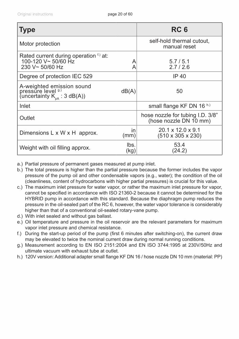
Type RC 6
Motor protection self-hold thermal cutout, manual reset
Rated current during operation f.) at: 100-120 V~ 50/60 Hz 230 V~ 50/60 Hz
AA
5.7 / 5.12.7 / 2.6
Degree of protection IEC 529 IP 40
A-weighted emission sound pressure level g.) (uncertainty KpA : 3 dB(A))
dB(A) 50
Inlet small flange KF DN 16 h.)
Outlet hose nozzle for tubing I.D. 3/8” (hose nozzle DN 10 mm)
Dimensions L x W x H approx. in(mm)
20.1 x 12.0 x 9.1(510 x 305 x 230)
Weight with oil filling approx. lbs.(kg)
53.4(24.2)
a.) Partial pressure of permanent gases measured at pump inlet.b.) The total pressure is higher than the partial pressure because the former includes the vapor
pressure of the pump oil and other condensable vapors (e.g., water); the condition of the oil (cleanliness, content of hydrocarbons with higher partial pressures) is crucial for this value.
c.) The maximum inlet pressure for water vapor, or rather the maximum inlet pressure for vapor, cannot be specified in accordance with ISO 21360-2 because it cannot be determined for the HYBRID pump in accordance with this standard. Because the diaphragm pump reduces the pressure in the oil-sealed part of the RC 6, however, the water vapor tolerance is considerably higher than that of a conventional oil-sealed rotary-vane pump.
d.) With inlet sealed and without gas ballast.e.) Oil temperature and pressure in the oil reservoir are the relevant parameters for maximum
vapor inlet pressure and chemical resistance. f.) During the start-up period of the pump (first 6 minutes after switching-on), the current draw
may be elevated to twice the nominal current draw during normal running conditions.g.) Measurement according to EN ISO 2151:2004 and EN ISO 3744:1995 at 230V/50Hz and
ultimate vacuum with exhaust tube at outlet. h.) 120V version: Additional adapter small flange KF DN 16 / hose nozzle DN 10 mm (material: PP)
page 21 of 60
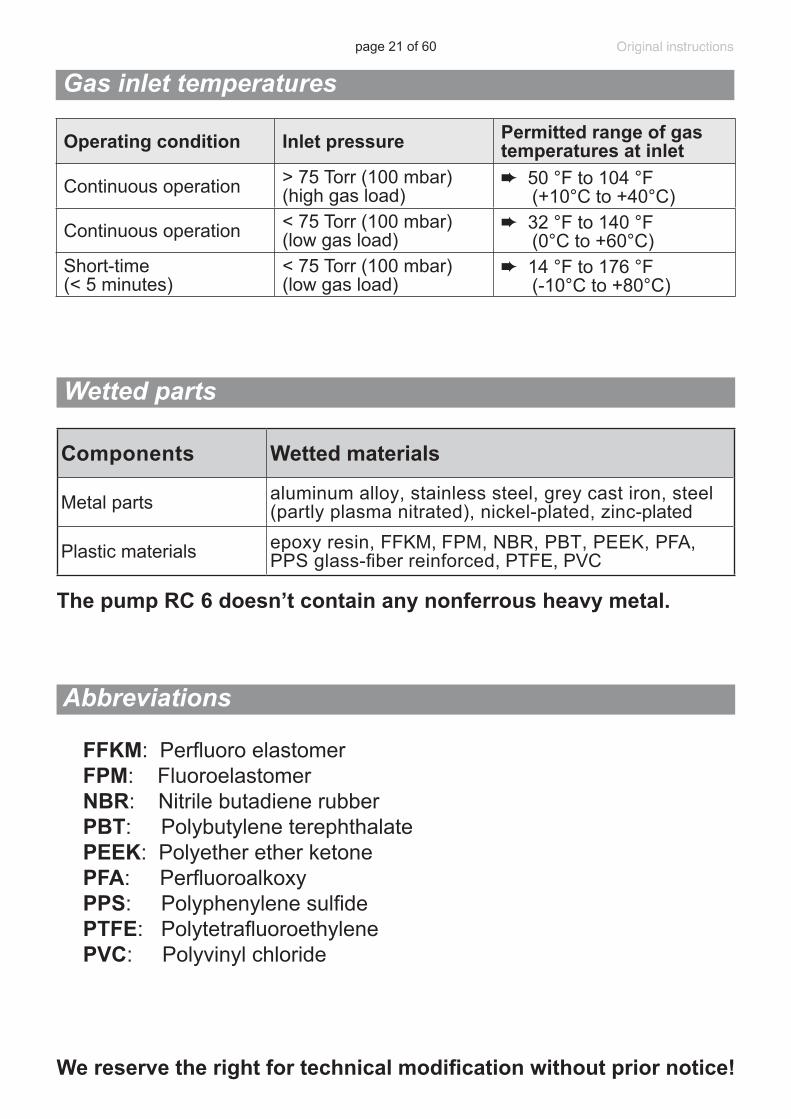
The pump RC 6 doesn’t contain any nonferrous heavy metal.
Components Wetted materials
Metal parts aluminum alloy, stainless steel, grey cast iron, steel (partly plasma nitrated), nickel-plated, zinc-plated
Plastic materials epoxy resin, FFKM, FPM, NBR, PBT, PEEK, PFA, PPS glass-fiber reinforced, PTFE, PVC
Wetted parts
We reserve the right for technical modification without prior notice!
Abbreviations
FFKM: Perfluoro elastomer FPM: Fluoroelastomer NBR: Nitrile butadiene rubber PBT: Polybutylene terephthalate PEEK: Polyether ether ketone PFA: Perfluoroalkoxy PPS: Polyphenylene sulfide PTFE: Polytetrafluoroethylene PVC: Polyvinyl chloride
Gas inlet temperatures
Operating condition Inlet pressure Permitted range of gas temperatures at inlet
Continuous operation > 75 Torr (100 mbar) (high gas load)
➨ 50 °F to 104 °F (+10°C to +40°C)
Continuous operation < 75 Torr (100 mbar) (low gas load)
➨ 32 °F to 140 °F (0°C to +60°C)
Short-time (< 5 minutes)
< 75 Torr (100 mbar) (low gas load)
➨ 14 °F to 176 °F (-10°C to +80°C)
page 22 of 60
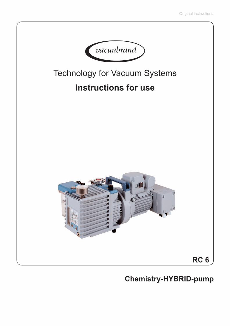
RC 61
5 3
4
7
6
8
10
9
2
12
11
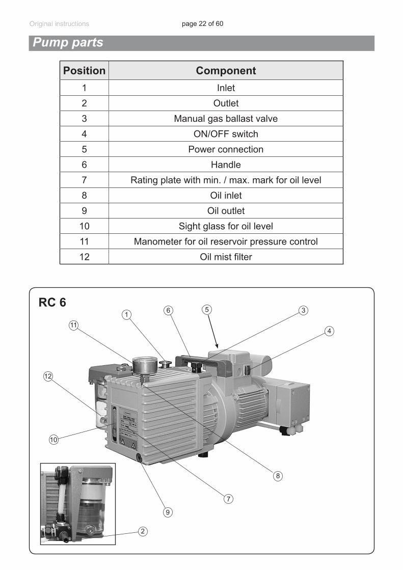
Position Component1 Inlet2 Outlet3 Manual gas ballast valve4 ON/OFF switch5 Power connection6 Handle7 Rating plate with min. / max. mark for oil level8 Oil inlet9 Oil outlet10 Sight glass for oil level11 Manometer for oil reservoir pressure control12 Oil mist filter
Pump parts
page 23 of 60
Method of operation:
The RC 6 is a four-stage vacuum pump consisting of an oil-sealed, two-stage rotary vane pump with a series-connected two-stage diaphragm pump. The two units are mounted on a common shaft and are connected directly to the drive motor. The dry-running compressor-type diaphragm pump evacuates the headspace of the oil reservoir of the rotary vane pump, thus considerably increasing the latter’s maximum vapor inlet pressure and chemical resistance.
With the gas ballast valve closed, the rotary vane pump shuts off vacuum tight. This, in turn, prolongs the intervals between oil changes and im-proves corrosion resistance. The oil system incorporates an oil pump; this forced-lubrication system ensures an adequate supply of oil to the pump unit even at high inlet pressures. A mechanical retaining valve in the oil system prevents oil suck-back into the vacuum system.The oil mist filter of the rotary vane pump removes 99 % of the oil mist. If an exhaust waste vapor condenser is fitted (available on request), the va-pors handled by the pump can be condensed to a large extent and either be recycled or disposed of in accordance with regulations.
Use and operation
page 24 of 60
Initial operation / Pouring in the pump oil
• The pump is supplied dry (i.e., without oil filling). This is in order to ensure that oil cannot make its way from the rotary vane pump into the housing of the oil mist filter during transport. A can containing 0.5 liter (0.53 quarts) of rotary-pump oil is supplied with the pump. Before starting the pump for the first time, pour in the oil as described below.
Pouring in the oil:
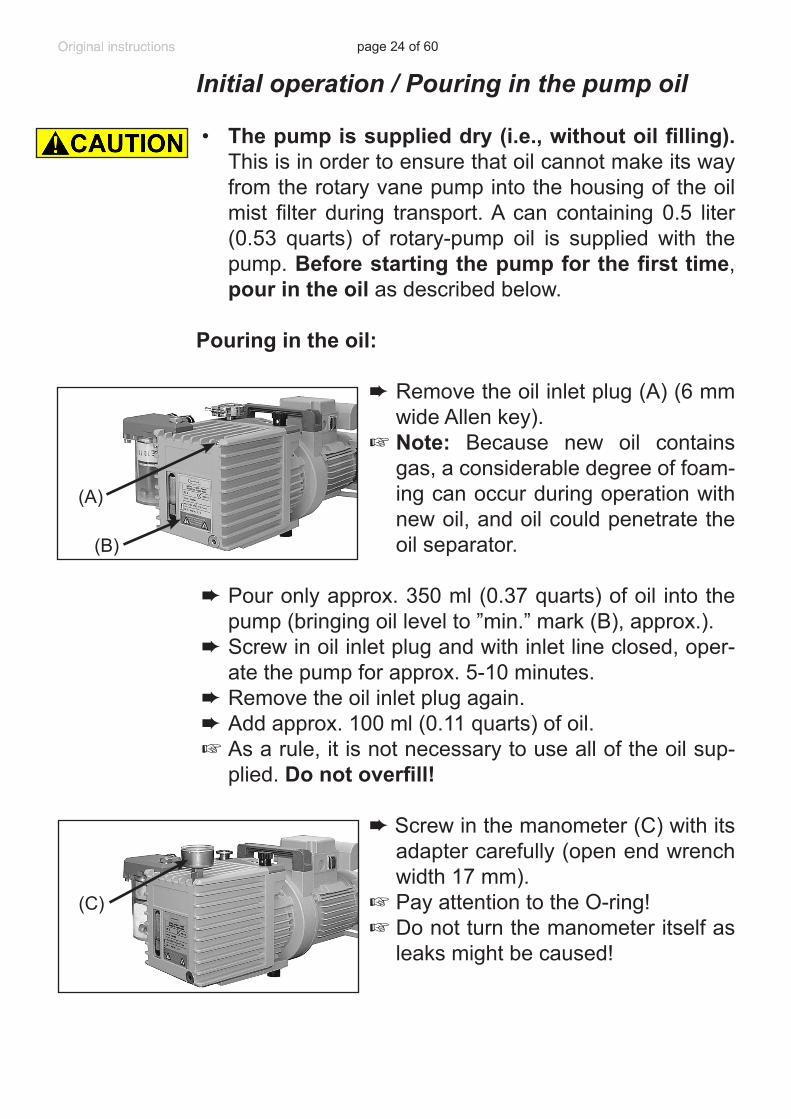
➨ Remove the oil inlet plug (A) (6 mm wide Allen key).
+ Note: Because new oil contains gas, a considerable degree of foam-ing can occur during operation with new oil, and oil could penetrate the oil separator.
➨ Pour only approx. 350 ml (0.37 quarts) of oil into the pump (bringing oil level to ”min.” mark (B), approx.).
➨ Screw in oil inlet plug and with inlet line closed, oper-ate the pump for approx. 5-10 minutes.
➨ Remove the oil inlet plug again.➨ Add approx. 100 ml (0.11 quarts) of oil.+As a rule, it is not necessary to use all of the oil sup-
plied. Do not overfill!
➨Screw in the manometer (C) with its adapter carefully (open end wrench width 17 mm).
+ Pay attention to the O-ring!+ Do not turn the manometer itself as
leaks might be caused!
(B)
(A)
(C)
page 25 of 60
Installing a pump in a vacuum system
➨If dangerous or polluting fluids, oil mist, or toxic or nox-ious gases could be released at the outlet, install an appropriate system to catch and dispose of those flu-ids or gases.
+ Connect a gas-tight exhaust line at the pump outlet if necessary. Always vent exhaust gases appropriately (e.g., into a fume hood). If needed, install an exhaust waste vapor condenser (see ”Accessories”, pg. 39).
+ Never block the gas outlet. The exhaust line must al-ways be free of obstructions (no back pressure) to en-sure an unimpeded discharge of gas. The cross-sec-tion of the outlet tubing must be at least the size of the pump’s exhaust connection.
+ Failure to connect the inlet and outlet lines correctly will cause overpressure and risk of bursting! The outlet (hose nozzle) is marked ”EX”.
+Particles and dust must not be aspirated. If necessary, you must install appropriate filters. You must ensure their suitability concerning gas flow, chemical resis-tance and resistance to clogging prior to use.
+Make sure ventilation is adequate, especially if the pump is installed in an enclosure, or if the ambient tempera-ture is elevated. Provide external ventilation, if neces-sary.
• Reduce the transmission of vibration. Prevent mechan-ical load due to rigid pipelines. Insert elastic hoses or flexible elements as couplings between the pump and rigid pipes.
Note: Flexible elements will compress or flatten when evacuated if not designed for use under vacuum.
• Hose connections at the pump inlet must always be gas tight.
page 26 of 60
• Install a cold trap in front of the pump, if pumping ag-gressive or corrosive gases or vapors.
• A power failure may cause accidental ventilation of the pump or the vacuum system, if the manual gas ballast valve is open. If this constitutes a potential source of danger, take appropriate safety measures, e.g., install a solenoid operated gas ballast valve (see “Accesso-ries”, pg. 39).
• The pump is supplied dry (i.e., without oil filling). Before starting the pump for the first time, pour in
the oil as described in the above section ”Initial opera-tion / Pouring in the pump oil”, pg. 24.
• Check the power source and the pump’s rating plate to be sure that the power source and the equipment match in voltage, phase, and frequency.
Keep a minimum distance of 2 in (5 cm) between the cool-ing fan and surrounding items (e.g., housing, walls, etc.), or else install an external automatic ventilation system.Use connecting hoses with large diameter and keep them as short as possible to avoid flow losses. Locate the pump as closely as possible to the application. Use only hoses at the inlet and outlet of the pump with an inner diameter at least as large as the diameter of the pump’s connec-tions. Always install outlet tubing descending from the pump or provide other measures to avoid backflow of condensate towards the pump.
Use a suitable valve (see”Accessories”, pg. 39) to iso-late the pump from the vacuum application. This is to allow the pump to warm up before pumping condensable vapors and to clean the pump after use before it is switched off.
When assembling, ensure vacuum-tightness. After as-sembly, check the whole system for leaks.
NOTICE
page 27 of 60
Secure hose connections at the pump appropriately, e.g., with hose clamps, to protect against accidental detach-ment.
Note: The pump must only be operated in a horizontal position. When transporting a pump containing oil, take great care not to tilt the pump to an angle that would allow oil to make its way into the filter element.
During operation
➨ Vent and dispose of potentially dangerous gases or vapors at the outlet of the pump appropriately.
+ Due to the high compression ratio, the pump might generate overpressure at the outlet. Check pressure compatibility with system components (e.g., exhaust tubing or exhaust valve) at the outlet. Ensure that the pump outlet is neither blocked nor restricted.
+Maximum ambient temperature: 104 °F (40 °C) Check the maximum temperatures, if installing the
pump in a cabinet or a housing. Make sure ventilation is adequate, especially if the ambient temperature is elevated.
• If the pump is installed at an altitude of more than 6500 ft (2000 m) above mean sea level, check compatibility with applicable safety requirements, and adopt suit-able measures. There is a risk of the motor overheat-ing due to insufficient cooling.
• Check compatibility with the maximally permitted pressures at inlet and outlet and the maximum pres-sure difference between inlet and outlet ports.
• Check the oil level of the rotary vane pump every time before starting the pump, however at least once a week.
page 28 of 60
Check the oil level more frequently if high amounts of gas or vapor are pumped.
• If pumping aggressive, corrosive or otherwise danger-ous gases and vapors, take appropriate measures to protect personnel, pump, and environment. Use ap-propriate equipment such as cold trap, separator, oil separator, full flow oil filter, shut-off valve, or exhaust waste vapor condenser (see “Accessories”, pg. 39) as well as special oil.
The ambient temperature should be at least 54°F (12 °C). Otherwise the pump may not start because of the high oil viscosity at low temperature.
Pumping down can be started at any pressure at the inlet below atmospheric pressure.Do not start the pump if the pressure at the outlet port exceeds 16.0 psi (1.1 bar) absolute.
Continuous operation is possible at any pressure below atmospheric pressure. Oil consumption will increase at inlet pressures above 75 Torr (100 mbar). Check oil level more frequently.
Prevent internal condensation, transfer of liquids or dust. The pump unit as well as the diaphragms and valves will be damaged if liquids are pumped in significant amounts. Check the pump regularly for external soiling and depos-its. Clean the pump if necessary to avoid an increase of the pump’s operating temperature.
The motor is protected by a self-hold thermal cutout in the winding.Note: Only a manual reset is possible. Switch off the pump and disconnect the electrical power cord. Identify and eliminate the cause of failure. Wait approximately five minutes before restarting the pump.
NOTICE
page 29 of 60
Avoid high heat supply (e.g., due to hot process gases). See “Technical data”, pg. 19, for maximum permitted gas and ambient temperatures.
A warm up period (approximately 30 min.) is required to ensure that the rated ultimate vacuum and pumping speed as well as the full vapor pumping rate and chemical resis-tance of the pump are attained. To warm up the pump effectively before connecting to the vacuum application, install a shut-off valve (see ”Accessories”, pg. 39).The attainable ultimate vacuum is limited by the properties of the vacuum vessel (leak-tightness, cleanliness and de-gassing of the inner surfaces), degassing of substances used and the condition of the pump oil (cleanliness, con-tent of hydrocarbons with higher partial pressures).
Use the manometer monitoring the pressure in the oil reservoir of the HYBRID pump to check the operability of the diaphragm pump. If during the process the pressure inside the oil reservoir should rise significantly (manome-ter needle clearly in the red zone), it is necessary to take appropriate measures to reduce the inlet pressure. For the HYBRID principle to work it is necessary to prevent the pumped vapors from condensing inside the oil reservoir. Therefore the pressure inside the oil reservoir has to be lower than the vapor pressure of the pumped media at the oil’s temperature (140°F (60°C)). If necessary, the volume of pumped vapors has to be reduced or a cold trap has to be installed. If no improvement is achieved even with the vacuum chamber being absolutely leak tight, this points to a po-tential failure of the diaphragm pump, e.g., a diaphragm crack. A more accurate check of the pressure inside the oil reservoir is possible with a more precise manometer, e.g., a DVR 2 digital vacuum gauge. If a pressure higher than 19 Torr (25 mbar) is measured with inlet port and gas bal-last valve closed, check the diaphragm pump and replace the diaphragms if necessary.Any drop in the diaphragm pump’s pumping speed pro-duces a pressure increase in the oil reservoir. Although
page 30 of 60
this does not have a direct effect on the pumping speed and on the ultimate vacuum attainable by the HYBRID pump, it does have a considerable effect on the aging of the oil and the HYBRID pump’s chemical resistance.All bearings are encapsulated and are filled with long-life lubricant. Under normal operating conditions, the drive system is maintenance free. The valves and diaphragms are wear parts. Aging of the oil of the rotary vane pump necessitates oil changes.
Important notes regarding the use of gas bal-last
Gas ballast is a continuous purge to keep the pump’s in-terior as clean as possible and to reduce the possibility of condensation inside the pump.
➨ Air and pumped media might react inside the pump or at the outlet of the pump and form hazardous or explo-sive mixtures, when you use air rather than inert gas for the gas ballast. This constitutes a risk of significant damage to equipment and/or facilities, a risk of per-sonal injury or even loss of life.
+ Make sure that air/gas intake through the gas ballast valve can never lead to hazardous, explosive or other-wise dangerous mixtures. If in doubt, use inert gas.
To reduce condensation in the pump, do not pump vapor before the pump has reached its operating temperature. Open the gas ballast valve when pumping condensable vapors.
NOTICE
page 31 of 60
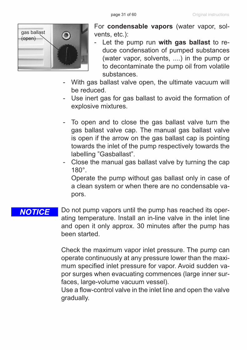
For condensable vapors (water vapor, sol-vents, etc.):- Let the pump run with gas ballast to re-
duce condensation of pumped substances (water vapor, solvents, ....) in the pump or to decontaminate the pump oil from volatile substances.
- With gas ballast valve open, the ultimate vacuum will be reduced.
- Use inert gas for gas ballast to avoid the formation of explosive mixtures.
- To open and to close the gas ballast valve turn the gas ballast valve cap. The manual gas ballast valve is open if the arrow on the gas ballast cap is pointing towards the inlet of the pump respectively towards the labelling ”Gasballast”.
- Close the manual gas ballast valve by turning the cap 180°.
Operate the pump without gas ballast only in case of a clean system or when there are no condensable va-pors.
Do not pump vapors until the pump has reached its oper-ating temperature. Install an in-line valve in the inlet line and open it only approx. 30 minutes after the pump has been started.
Check the maximum vapor inlet pressure. The pump can operate continuously at any pressure lower than the maxi-mum specified inlet pressure for vapor. Avoid sudden va-por surges when evacuating commences (large inner sur-faces, large-volume vacuum vessel). Use a flow-control valve in the inlet line and open the valve gradually.
gas ballast (open)
NOTICE
page 32 of 60
Operating the pump with condensate in the catchpots
Observe the condensate levels in the catchpots of the sep-arator at the inlet and of the oil mist filter. The condensate level in an optional separator at the inlet must always be kept below the bottom of the separator tube. The conden-sate level in the oil mist filter must always be kept below the bottom edge of the filter. Drain condensate in time. To drain condensate, switch off and vent the pump. Then open drain screw of the catch-pot. Condensate of the inlet catchpot (see ”Accessories”, pg. 39) in particular must not be drained while pump is operating.In case of a clogged filter, oil mist might be visible in the oil filter housing, or the filter might be discolored or exhibit deposits on the inside. If the filter element is clogged, dis-assemble the oil mist filter and replace the filter element.Under certain circumstances, clogged filter elements can be cleaned using suitable solvents. However, it is safer to use a new filter element (see section ”Replacing the filter element in the oil mist filter”, pg. 52).
Do not reuse separated oil if it is contaminated or discol-ored.
+ Important: Comply with regulations when disposing of solvents/condensates. Recycle if possible; purify if contaminated.
NOTICE
page 33 of 60
Pumping chemically aggressive or toxic gas-es and vapors
➨Avoid explosive conditions when compressing explo-sible and flammable substances/mixtures. In such in-stances, use inert gas for gas ballast.
Attention: The gas ballast of the diaphragm pump is permanently connected to the system.
+ Implement special protective measures to protect per-sonnel, pump, and environment.
• Install a cold trap (see ”Accessories”, pg. 39), if the thermodynamic conditions of the application are such that vapors could condense in the rotary vane pump.
Wait until the pump has reached its operating temper-ature before connecting it to the vacuum system.
Before switching off, allow the pump to run for a few min-utes, initially with the rotary vane pump‘s gas ballast valve open and then with the gas ballast valve closed, after the pump has been isolated from the vacuum application. Prevent internal condensation, transfer of liquids or dust.The pump requires regular inspection and maintenance.
NOTICE
page 34 of 60
ShutdownHas the pump been exposed to condensate?- Allow the pump to continue to run for a few minutes
with the rotary vane pump’s gas ballast valve open be-fore switching off.
Long-term:- Separate the pump from the application.- Drain condensates (catchpots of the separator at the
inlet and of the oil mist filter).- Flush the pump with dry nitrogen.- Carry out oil change (see “Oil change”, pg. 35).- Fill the pump completely with new oil (to above the
”max.” mark!). Attention: Before restarting the pump, drain oil to the
maximum oil level (”max.” mark)!- Close the manual gas ballast valve.- Close inlet and outlet ports (e.g., with transport caps or
blind flanges).- Store the pump under dry conditions.
- Carry out oil change and maintenance prior to use if the pump has been stored for longer than one year.
Note: When transporting a pump containing oil, take great care not to tilt the pump to an angle that would allow oil to make its way into the filter element. Drain oil if necessary.
NOTICE
page 35 of 60
Oil change➨ Never operate the pump if parts of the pump are dis-
assembled. Ensure that the pump cannot be operated accidentally.
➨Before starting maintenance, isolate the pump from its application and disconnect the electrical power cord.
➨ Note: The pump or the pump oil might be contaminated
with dangerous or corrosive process chemicals that have been pumped during operation. Adopt suitable decontamination measures if necessary. Take ade-quate precautions to protect people from the effects of dangerous substances if contamination has occurred. Ensure that the maintenance technician is familiar with the safety procedures which relate to the products pro-cessed by the pumping system.
+ Use appropriate protective clothing, safety goggles
and protective gloves. Avoid inhalation and skin con-tact.
• Take adequate precautions when handling pump flu-ids, lubricants, and solvents. Use appropriate protective clothing, safety goggles and protective gloves to avoid excessive contact with the skin and possible skin irrita-tions (including dermatitis).
Comply with all relevant statutory requirements and regulations concerning the handling, storage and dis-posal of oil.
Aging of the oil (as indicated by darker color compared to new oil, strange odor of the oil, particles in the oil, or con-tamination) necessitates an oil change.Depending on the application (especially if corrosive gas-es or vapors have been pumped) it may be appropriate to check the oil frequently and to carry out an oil change, if necessary.
NOTICE
page 36 of 60
Under normal operating conditions:- Check oil level every time before starting the pump.- Carry out an oil change once aging of the oil is indi-
cated by darker color compared to new oil.- Carry out oil changes at least once a year.- Dispose of the used oil, which may be contaminated,
according to all applicable regulations.
If the oil contains small quantities of water/solvent:+ The oil can be cleaned to a certain extent by operating
the pump for 1 - 2 hours with the inlet line sealed and the gas ballast valve open.
Oil change procedure
+ Carry out the oil change only after the pump has reached its normal operating temperature.
➨ Switch off the pump and isolate it from its application. Ventilate the pump to atmospheric pressure. Discon-nect the electrical power cord. To vent the oil reservoir, remove the manometer with its adapter carefully (open end wrench width 17 mm). Pay attention to the O-ring! Do not turn the manometer itself as leaks might be caused!
+ Choose a suitable pad; oil may drip. Use a suitable container to catch the oil.
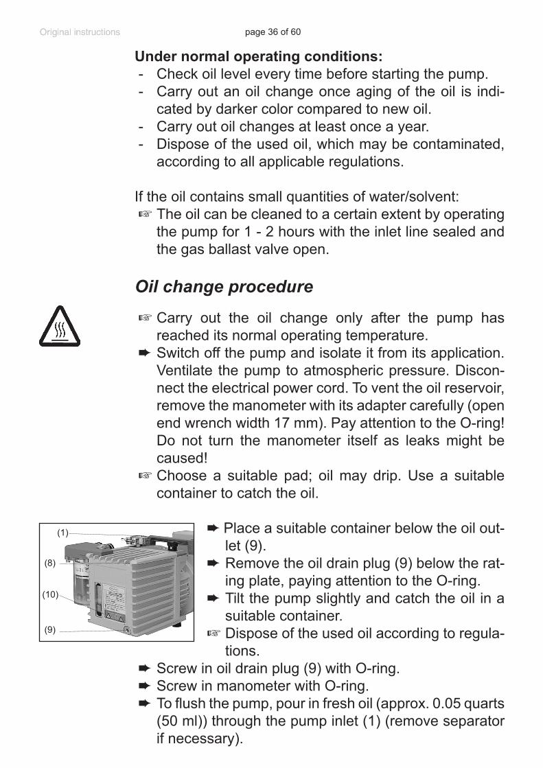
➨Place a suitable container below the oil out-let (9).
➨ Remove the oil drain plug (9) below the rat-ing plate, paying attention to the O-ring.
➨ Tilt the pump slightly and catch the oil in a suitable container.
+ Dispose of the used oil according to regula-tions.
➨ Screw in oil drain plug (9) with O-ring.➨ Screw in manometer with O-ring.➨ To flush the pump, pour in fresh oil (approx. 0.05 quarts
(50 ml)) through the pump inlet (1) (remove separator if necessary).
(8)
(9)
(1)
(10)
page 37 of 60
➨ Operate the pump briefly. Drain flushing oil and repeat flushing procedure, if necessary, until all contamina-tions are flushed out.
➨ Remove the manometer (see above). Add fresh oil (at first approx. 0.37 quarts (350 ml) only) through the oil inlet port for the oil level to reach the ”min.” mark (10).
➨ Close the oil inlet port (8). Operate the pump with closed inlet for approx. 5-10 minutes.
➨ Top off the oil (add approx. 0.11 quarts (100 ml)). As a rule, it is not necessary to use the maximum quantity of oil. Do not overfill!
➨ Screw in manometer with O-ring.
Note: The oil degasses and foams at low pressures. This is a welcome condition which helps to protect the pump against corrosion and to prolong the working life of the oil.
The quantity, condition and quality of the pump oil have a decisive effect on the pump’s performance and depend-ability. Important: It may not be possible to reach the specified ultimate vacuum if an oil other than VACUUBRAND B-oil is used. Similarly, failure to use the recommended oil may impair cold-start performance and pump lubrication!
Notes on choosing the appropriate oil for the applicationThe standard oil for VACUUBRAND rotary vane pumps is the B-oil. This is a mineral oil, which is used for the first filling of the pump.The advantages of the B-oil are: Flat viscosity curve, low vapor pressure, good chemical resistance, extended stability when pumping oxidants, acid or basic vapors compared to conventional mineral oils, and good skin compatibility.
Certain pumped media may attack the conventional oil in the pump. Spe-cial oils can be used preventively. It is at the users’ responsibility to check if the materials of the wetted parts are resistant against the pumped sub-stances. This is also mandatory if special oils are used.
page 38 of 60
Special oils:
Rotary vane pump oil K8 The rotary vane pump oil K8 is a special oil designed for pumping acid vapors. The oil is very hygroscopic and has a limited capacity for acids. With decreasing pH, the anticorrosive effect decreases as well, and it is necessary to change the oil at appropriate intervals. When the pump will stand still for prolonged periods (i.e., for several days), the oil must be drained and the pump must be filled with mineral oil.
Synthetic oil (perfluoropolyether oil, e.g., Fomblin®*)Synthetic oils have an excellent chemical resistance and are certified for pumping pure oxygen. Therefore these oils are excellent for handling strong oxidants, e.g., halogens, nitrogen oxides, etc.Attention: As perfluoropolyether oils mixed with mineral oils result in an emulsion, pumps used with these oils must be absolutely free of any residues of mineral oils. To accomplish this, you must completely disas-semble and diligently clean the pump unit.
* reg. trade mark Montedison
Attention if using special oils: Due to a different viscosity / density com-pared to the standard oil, pumps filled with special oil may not achieve the specified ultimate pressure, or the pumps may not start reliably at temperatures below 54°F (12°C).
VACUUBRAND B-oil1 liter (1.06 qt) ...............................................................................................6870105 liter (5.3 qt) .................................................................................................68701120 liter (5.3 gal)..............................................................................................687012200 liter (52.8 gal)..........................................................................................687013
Rotary vane pump oil K81 liter (1.06 qt) ...............................................................................................687100 5 liter (5.3 qt) .................................................................................................68710120 liter (5.3 gal)..............................................................................................687102
Perfluoropolyether oil500 ml (0.53 qt) .............................................................................................687600
page 39 of 60
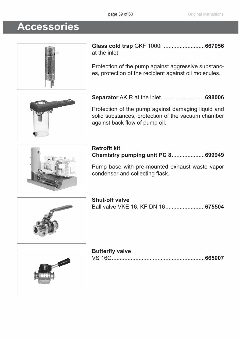
Separator AK R at the inlet ............................698006
Protection of the pump against damaging liquid and solid substances, protection of the vacuum chamber against back flow of pump oil.
Retrofit kit Chemistry pumping unit PC 8 .....................699949
Pump base with pre-mounted exhaust waste vapor condenser and collecting flask.
Shut-off valveBall valve VKE 16, KF DN 16 .........................675504
Butterfly valve VS 16C ...........................................................665007
AccessoriesGlass cold trap GKF 1000i ...........................667056 at the inlet
Protection of the pump against aggressive substanc-es, protection of the recipient against oil molecules.
page 40 of 60
Maintenance kit RC 6 .................................................................................649990(rotary vane pump and diaphragm pump)
Hose nipple, aluminum, for hoses DN 19.....................................................662531
Vacuum hose (rubber, DN 20)......................................................................686005
PTFE vacuum hose (antistatic) with stainless steel small flanges. The inner side of the PTFE hose is smooth for increased chemical resistance, reduced deposits and high conductanceKF DN 16, 500 mm (19.7”) ............................................................................686030KF DN 16, 1000 mm (39.4”) ..........................................................................686031KF DN 25, 500 mm (19.7”) ............................................................................686032KF DN 25, 1000 mm (39.4”) ..........................................................................686033
Vacuum gauge DCP 3000 with gauge head VSP 3000 (Pirani), 7.5*102 Torr - 1*10-3 Torr (1*103 mbar - 1*10-3 mbar) .....................................683190 100-230V 50/60 Hz
➨ A service manual with exploded view drawings, spare parts list and directions for repair is available on request.
+The service manual is intended for trained service people only.
page 41 of 60
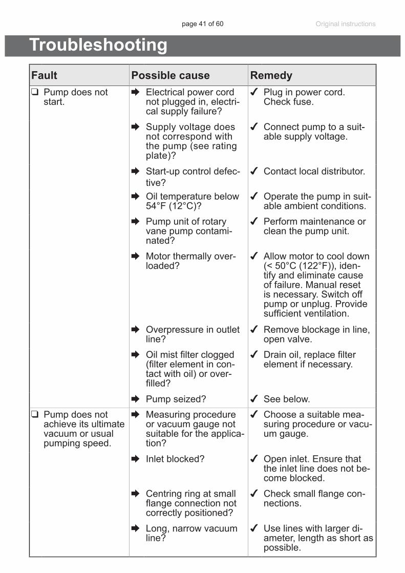
TroubleshootingFault Possible cause Remedy❑ Pump does not
start.➨ Electrical power cord
not plugged in, electri-cal supply failure?
✔ Plug in power cord. Check fuse.
➨ Supply voltage does not correspond with the pump (see rating plate)?
✔ Connect pump to a suit-able supply voltage.
➨ Start-up control defec-tive?
✔ Contact local distributor.
➨ Oil temperature below 54°F (12°C)?
✔ Operate the pump in suit-able ambient conditions.
➨ Pump unit of rotary vane pump contami-nated?
✔ Perform maintenance or clean the pump unit.
➨ Motor thermally over-loaded?
✔ Allow motor to cool down (< 50°C (122°F)), iden-tify and eliminate cause of failure. Manual reset is necessary. Switch off pump or unplug. Provide sufficient ventilation.
➨ Overpressure in outlet line?
✔ Remove blockage in line, open valve.
➨ Oil mist filter clogged (filter element in con-tact with oil) or over-filled?
✔ Drain oil, replace filter element if necessary.
➨ Pump seized? ✔ See below.❑ Pump does not
achieve its ultimate vacuum or usual pumping speed.
➨ Measuring procedure or vacuum gauge not suitable for the applica-tion?
✔ Choose a suitable mea-suring procedure or vacu-um gauge.
➨ Inlet blocked? ✔ Open inlet. Ensure that the inlet line does not be-come blocked.
➨ Centring ring at small flange connection not correctly positioned?
✔ Check small flange con-nections.
➨ Long, narrow vacuum line?
✔ Use lines with larger di-ameter, length as short as possible.
page 42 of 60
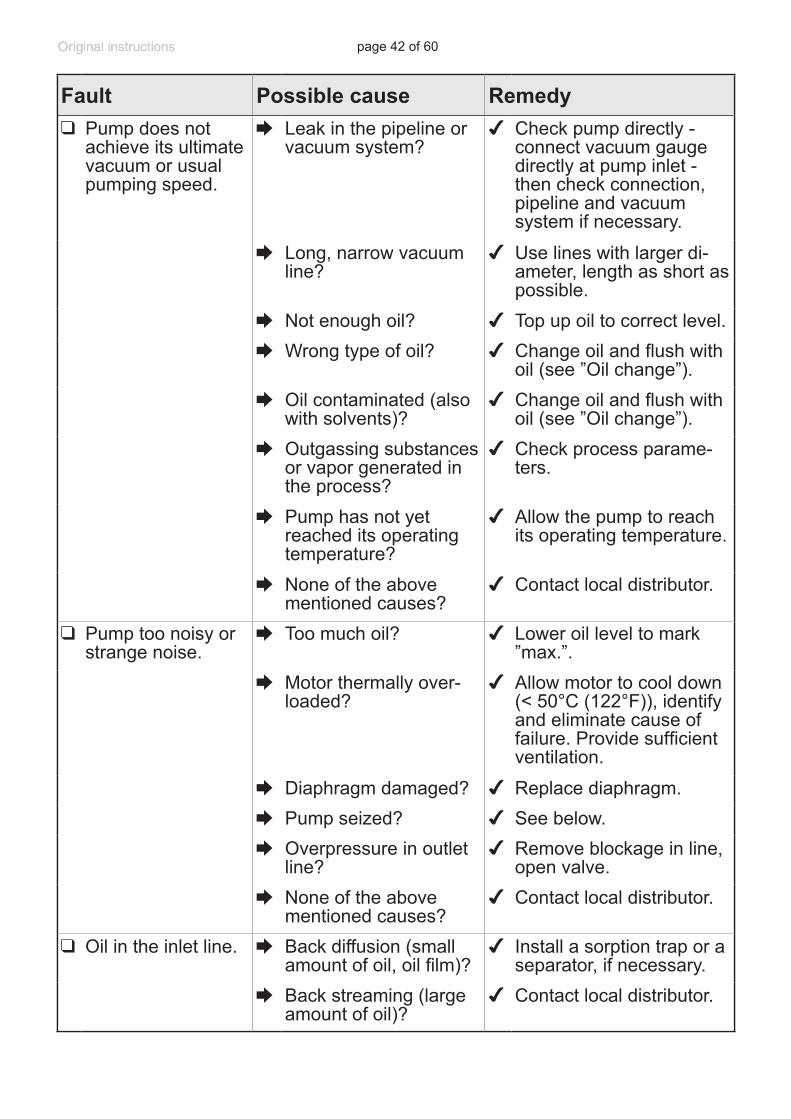
Fault Possible cause Remedy❑ Pump does not
achieve its ultimate vacuum or usual pumping speed.
➨ Leak in the pipeline or vacuum system?
✔ Check pump directly - connect vacuum gauge directly at pump inlet - then check connection, pipeline and vacuum system if necessary.
➨ Long, narrow vacuum line?
✔ Use lines with larger di-ameter, length as short as possible.
➨ Not enough oil? ✔ Top up oil to correct level.➨ Wrong type of oil? ✔ Change oil and flush with
oil (see ”Oil change”).➨ Oil contaminated (also
with solvents)?✔ Change oil and flush with
oil (see ”Oil change”).➨ Outgassing substances
or vapor generated in the process?
✔ Check process parame-ters.
➨ Pump has not yet reached its operating temperature?
✔ Allow the pump to reach its operating temperature.
➨ None of the above mentioned causes?
✔ Contact local distributor.
❑ Pump too noisy or strange noise.
➨ Too much oil? ✔ Lower oil level to mark ”max.”.
➨ Motor thermally over-loaded?
✔ Allow motor to cool down (< 50°C (122°F)), identify and eliminate cause of failure. Provide sufficient ventilation.
➨ Diaphragm damaged? ✔ Replace diaphragm.➨ Pump seized? ✔ See below.➨ Overpressure in outlet
line?✔ Remove blockage in line,
open valve.➨ None of the above
mentioned causes?✔ Contact local distributor.
❑ Oil in the inlet line. ➨ Back diffusion (small amount of oil, oil film)?
✔ Install a sorption trap or a separator, if necessary.
➨ Back streaming (large amount of oil)?
✔ Contact local distributor.
page 43 of 60
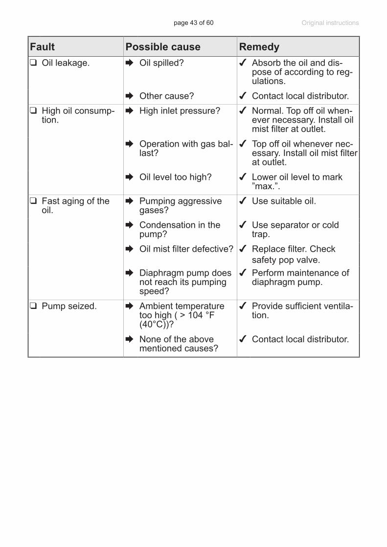
Fault Possible cause Remedy❑ Oil leakage. ➨ Oil spilled? ✔ Absorb the oil and dis-
pose of according to reg-ulations.
➨ Other cause? ✔ Contact local distributor.❑ High oil consump-
tion.➨ High inlet pressure? ✔ Normal. Top off oil when-
ever necessary. Install oil mist filter at outlet.
➨ Operation with gas bal-last?
✔ Top off oil whenever nec-essary. Install oil mist filter at outlet.
➨ Oil level too high? ✔ Lower oil level to mark ”max.”.
❑ Fast aging of the oil.
➨ Pumping aggressive gases?
✔ Use suitable oil.
➨ Condensation in the pump?
✔ Use separator or cold trap.
➨ Oil mist filter defective? ✔ Replace filter. Check safety pop valve.
➨ Diaphragm pump does not reach its pumping speed?
✔ Perform maintenance of diaphragm pump.
❑ Pump seized. ➨ Ambient temperature too high ( > 104 °F (40°C))?
✔ Provide sufficient ventila-tion.
➨ None of the above mentioned causes?
✔ Contact local distributor.
page 44 of 60
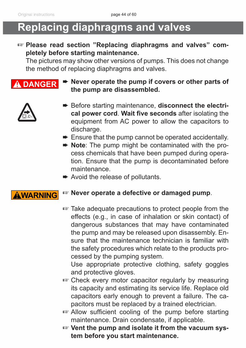
Replacing diaphragms and valves+ Please read section ”Replacing diaphragms and valves” com-
pletely before starting maintenance. The pictures may show other versions of pumps. This does not change
the method of replacing diaphragms and valves.
➨ Never operate the pump if covers or other parts of the pump are disassembled.
➨ Before starting maintenance, disconnect the electri-cal power cord. Wait five seconds after isolating the equipment from AC power to allow the capacitors to discharge.
➨ Ensure that the pump cannot be operated accidentally. ➨ Note: The pump might be contaminated with the pro-
cess chemicals that have been pumped during opera-tion. Ensure that the pump is decontaminated before maintenance.
➨ Avoid the release of pollutants.
+Never operate a defective or damaged pump.
+Take adequate precautions to protect people from the effects (e.g., in case of inhalation or skin contact) of dangerous substances that may have contaminated the pump and may be released upon disassembly. En-sure that the maintenance technician is familiar with the safety procedures which relate to the products pro-cessed by the pumping system.
Use appropriate protective clothing, safety goggles and protective gloves.
+ Check every motor capacitor regularly by measuring its capacity and estimating its service life. Replace old capacitors early enough to prevent a failure. The ca-pacitors must be replaced by a trained electrician.
+ Allow sufficient cooling of the pump before starting maintenance. Drain condensate, if applicable.
+ Vent the pump and isolate it from the vacuum sys-tem before you start maintenance.
page 45 of 60
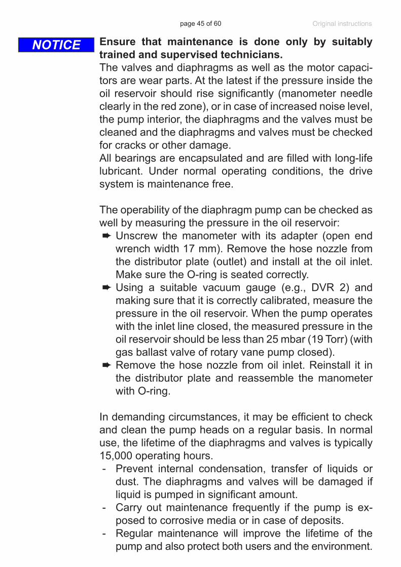
Ensure that maintenance is done only by suitably trained and supervised technicians.The valves and diaphragms as well as the motor capaci-tors are wear parts. At the latest if the pressure inside the oil reservoir should rise significantly (manometer needle clearly in the red zone), or in case of increased noise level, the pump interior, the diaphragms and the valves must be cleaned and the diaphragms and valves must be checked for cracks or other damage. All bearings are encapsulated and are filled with long-life lubricant. Under normal operating conditions, the drive system is maintenance free.
The operability of the diaphragm pump can be checked as well by measuring the pressure in the oil reservoir:➨ Unscrew the manometer with its adapter (open end
wrench width 17 mm). Remove the hose nozzle from the distributor plate (outlet) and install at the oil inlet. Make sure the O-ring is seated correctly.
➨ Using a suitable vacuum gauge (e.g., DVR 2) and making sure that it is correctly calibrated, measure the pressure in the oil reservoir. When the pump operates with the inlet line closed, the measured pressure in the oil reservoir should be less than 25 mbar (19 Torr) (with gas ballast valve of rotary vane pump closed).
➨ Remove the hose nozzle from oil inlet. Reinstall it in the distributor plate and reassemble the manometer with O-ring.
In demanding circumstances, it may be efficient to check and clean the pump heads on a regular basis. In normal use, the lifetime of the diaphragms and valves is typically 15,000 operating hours.- Prevent internal condensation, transfer of liquids or
dust. The diaphragms and valves will be damaged if liquid is pumped in significant amount.
- Carry out maintenance frequently if the pump is ex-posed to corrosive media or in case of deposits.
- Regular maintenance will improve the lifetime of the pump and also protect both users and the environment.
NOTICE
page 46 of 60
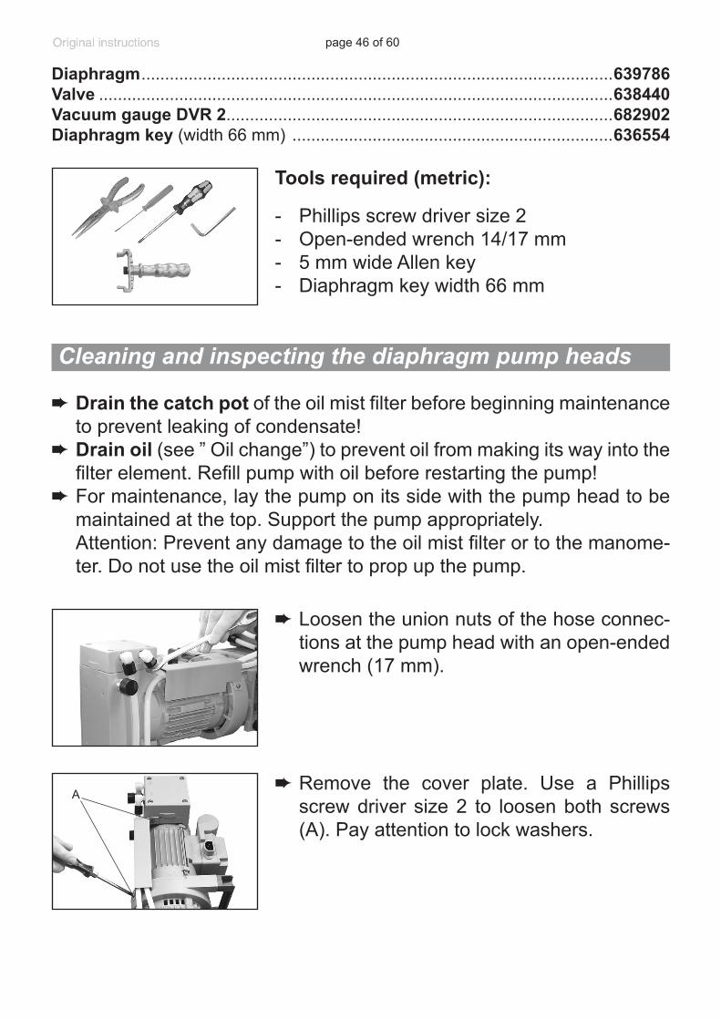
➨ Drain the catch pot of the oil mist filter before beginning maintenance to prevent leaking of condensate!
➨ Drain oil (see ” Oil change”) to prevent oil from making its way into the filter element. Refill pump with oil before restarting the pump!
➨ For maintenance, lay the pump on its side with the pump head to be maintained at the top. Support the pump appropriately.
Attention: Prevent any damage to the oil mist filter or to the manome-ter. Do not use the oil mist filter to prop up the pump.
➨ Loosen the union nuts of the hose connec-tions at the pump head with an open-ended wrench (17 mm).
Tools required (metric):
- Phillips screw driver size 2- Open-ended wrench 14/17 mm- 5 mm wide Allen key- Diaphragm key width 66 mm
Diaphragm ....................................................................................................639786Valve .............................................................................................................638440Vacuum gauge DVR 2..................................................................................682902Diaphragm key (width 66 mm) ....................................................................636554
Cleaning and inspecting the diaphragm pump heads
➨ Remove the cover plate. Use a Phillips screw driver size 2 to loosen both screws (A). Pay attention to lock washers.
A
page 47 of 60
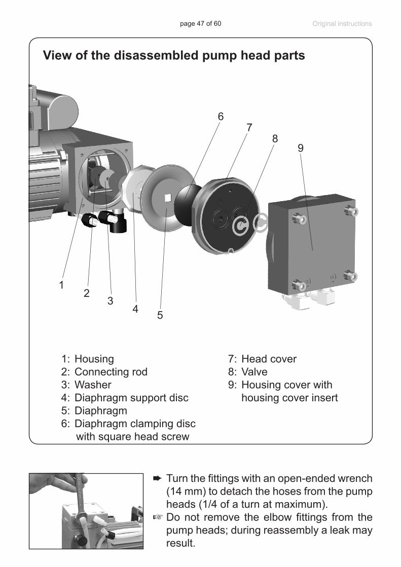
➨ Turn the fittings with an open-ended wrench (14 mm) to detach the hoses from the pump heads (1/4 of a turn at maximum).
+ Do not remove the elbow fittings from the pump heads; during reassembly a leak may result.
1
9
32
5
67
8
4
1: Housing2: Connecting rod3: Washer4: Diaphragm support disc5: Diaphragm6: Diaphragm clamping disc with square head screw
7: Head cover8: Valve9: Housing cover with
housing cover insert
View of the disassembled pump head parts
page 48 of 60
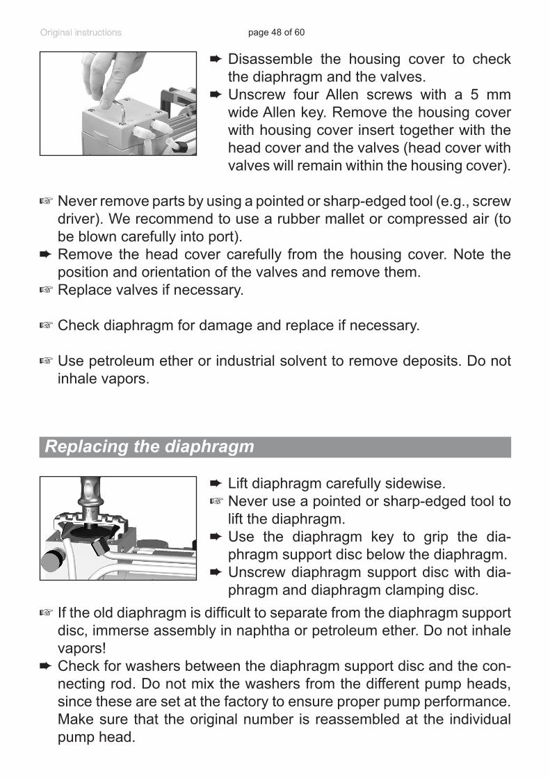
➨ Disassemble the housing cover to check the diaphragm and the valves.
➨Unscrew four Allen screws with a 5 mm wide Allen key. Remove the housing cover with housing cover insert together with the head cover and the valves (head cover with valves will remain within the housing cover).
+ Never remove parts by using a pointed or sharp-edged tool (e.g., screw driver). We recommend to use a rubber mallet or compressed air (to be blown carefully into port).
➨ Remove the head cover carefully from the housing cover. Note the position and orientation of the valves and remove them.
+ Replace valves if necessary.
+ Check diaphragm for damage and replace if necessary.
+ Use petroleum ether or industrial solvent to remove deposits. Do not inhale vapors.
Replacing the diaphragm
➨ Lift diaphragm carefully sidewise.+ Never use a pointed or sharp-edged tool to
lift the diaphragm.➨ Use the diaphragm key to grip the dia-
phragm support disc below the diaphragm. ➨Unscrew diaphragm support disc with dia-
phragm and diaphragm clamping disc.+ If the old diaphragm is difficult to separate from the diaphragm support
disc, immerse assembly in naphtha or petroleum ether. Do not inhale vapors!
➨ Check for washers between the diaphragm support disc and the con-necting rod. Do not mix the washers from the different pump heads, since these are set at the factory to ensure proper pump performance. Make sure that the original number is reassembled at the individual pump head.
page 49 of 60
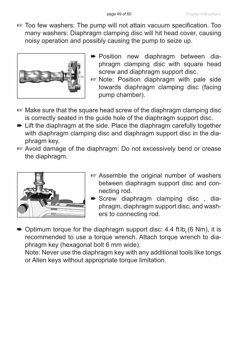
➨ Position new diaphragm between dia-phragm clamping disc with square head screw and diaphragm support disc.
+ Note: Position diaphragm with pale side towards diaphragm clamping disc (facing pump chamber).
+ Make sure that the square head screw of the diaphragm clamping disc is correctly seated in the guide hole of the diaphragm support disc.
➨ Lift the diaphragm at the side. Place the diaphragm carefully together with diaphragm clamping disc and diaphragm support disc in the dia-phragm key.
+ Avoid damage of the diaphragm: Do not excessively bend or crease the diaphragm.
+ Assemble the original number of washers between diaphragm support disc and con-necting rod.
➨ Screw diaphragm clamping disc , dia-phragm, diaphragm support disc, and wash-ers to connecting rod.
➨ Optimum torque for the diaphragm support disc: 4.4 ft.lbf (6 Nm), it is recommended to use a torque wrench. Attach torque wrench to dia-phragm key (hexagonal bolt 6 mm wide).
Note: Never use the diaphragm key with any additional tools like tongs or Allen keys without appropriate torque limitation.
+ Too few washers: The pump will not attain vacuum specification. Too many washers: Diaphragm clamping disc will hit head cover, causing noisy operation and possibly causing the pump to seize up.
page 50 of 60
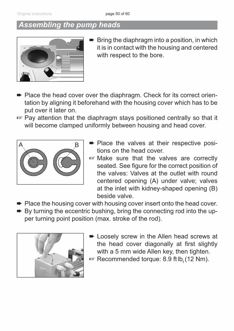
➨ Bring the diaphragm into a position, in which it is in contact with the housing and centered with respect to the bore.
Assembling the pump heads
➨ Place the head cover over the diaphragm. Check for its correct orien-tation by aligning it beforehand with the housing cover which has to be put over it later on.
+ Pay attention that the diaphragm stays positioned centrally so that it will become clamped uniformly between housing and head cover.
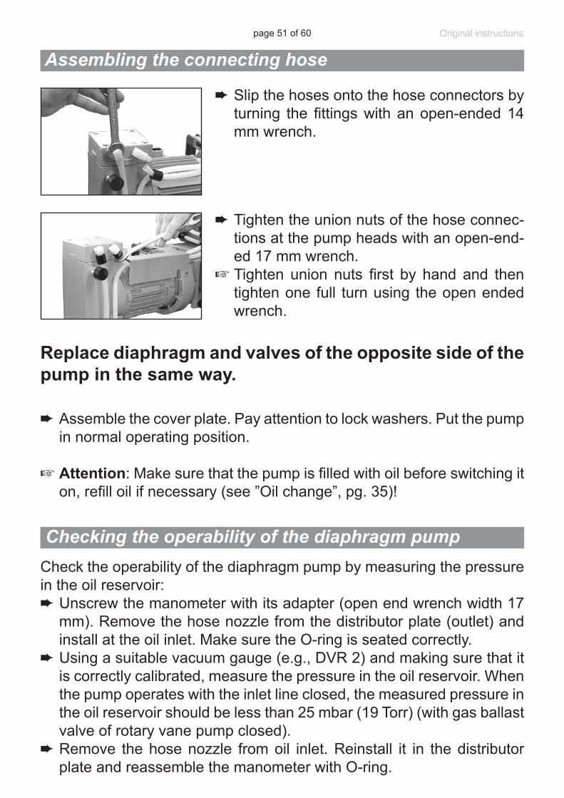
➨ Place the valves at their respective posi-tions on the head cover.
+ Make sure that the valves are correctly seated. See figure for the correct position of the valves: Valves at the outlet with round centered opening (A) under valve; valves at the inlet with kidney-shaped opening (B) beside valve.
➨ Place the housing cover with housing cover insert onto the head cover.➨ By turning the eccentric bushing, bring the connecting rod into the up-
per turning point position (max. stroke of the rod).
A B
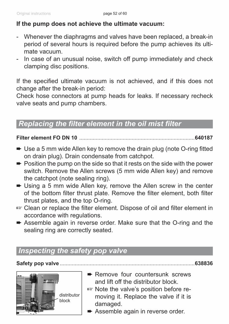
➨ Loosely screw in the Allen head screws at the head cover diagonally at first slightly with a 5 mm wide Allen key, then tighten.
+ Recommended torque: 8.9 ft.lbf (12 Nm).
page 51 of 60
➨ Assemble the cover plate. Pay attention to lock washers. Put the pump in normal operating position.
+ Attention: Make sure that the pump is filled with oil before switching it on, refill oil if necessary (see ”Oil change”, pg. 35)!
Check the operability of the diaphragm pump by measuring the pressure in the oil reservoir:➨ Unscrew the manometer with its adapter (open end wrench width 17
mm). Remove the hose nozzle from the distributor plate (outlet) and install at the oil inlet. Make sure the O-ring is seated correctly.
➨ Using a suitable vacuum gauge (e.g., DVR 2) and making sure that it is correctly calibrated, measure the pressure in the oil reservoir. When the pump operates with the inlet line closed, the measured pressure in the oil reservoir should be less than 25 mbar (19 Torr) (with gas ballast valve of rotary vane pump closed).
➨ Remove the hose nozzle from oil inlet. Reinstall it in the distributor plate and reassemble the manometer with O-ring.
Assembling the connecting hose
➨ Slip the hoses onto the hose connectors by turning the fittings with an open-ended 14 mm wrench.
➨ Tighten the union nuts of the hose connec-tions at the pump heads with an open-end-ed 17 mm wrench.
+ Tighten union nuts first by hand and then tighten one full turn using the open ended wrench.
Replace diaphragm and valves of the opposite side of the pump in the same way.
Checking the operability of the diaphragm pump
page 52 of 60
➨ Use a 5 mm wide Allen key to remove the drain plug (note O-ring fitted on drain plug). Drain condensate from catchpot.
➨ Position the pump on the side so that it rests on the side with the power switch. Remove the Allen screws (5 mm wide Allen key) and remove the catchpot (note sealing ring).
➨ Using a 5 mm wide Allen key, remove the Allen screw in the center of the bottom filter thrust plate. Remove the filter element, both filter thrust plates, and the top O-ring.
+ Clean or replace the filter element. Dispose of oil and filter element in accordance with regulations.
➨ Assemble again in reverse order. Make sure that the O-ring and the sealing ring are correctly seated.
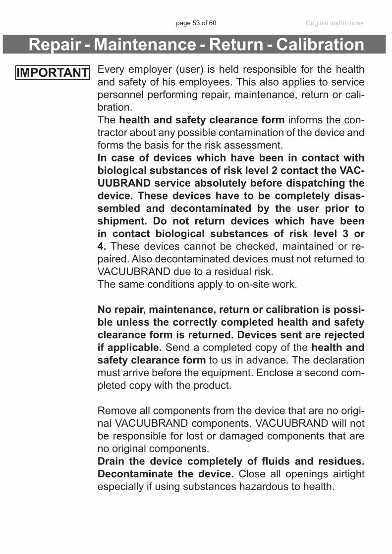
distributor block
➨Remove four countersunk screws and lift off the distributor block.
+ Note the valve’s position before re-moving it. Replace the valve if it is damaged.
➨ Assemble again in reverse order.
Safety pop valve ..........................................................................................638836
Filter element FO DN 10 .............................................................................640187
If the pump does not achieve the ultimate vacuum:
- Whenever the diaphragms and valves have been replaced, a break-in period of several hours is required before the pump achieves its ulti-mate vacuum.
- In case of an unusual noise, switch off pump immediately and check clamping disc positions.
If the specified ultimate vacuum is not achieved, and if this does not change after the break-in period:Check hose connectors at pump heads for leaks. If necessary recheck valve seats and pump chambers.
Replacing the filter element in the oil mist filter
Inspecting the safety pop valve
page 53 of 60
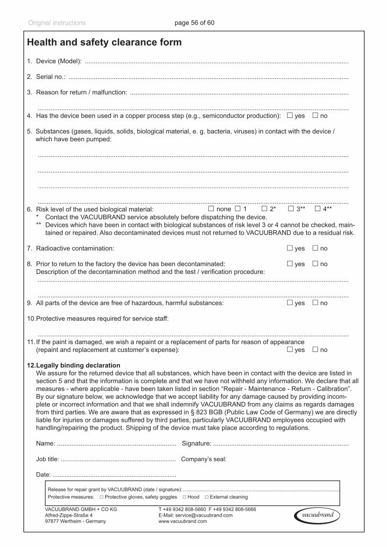
Every employer (user) is held responsible for the health and safety of his employees. This also applies to service personnel performing repair, maintenance, return or cali-bration.The health and safety clearance form informs the con-tractor about any possible contamination of the device and forms the basis for the risk assessment. In case of devices which have been in contact with biological substances of risk level 2 contact the VAC-UUBRAND service absolutely before dispatching the device. These devices have to be completely disas-sembled and decontaminated by the user prior to shipment. Do not return devices which have been in contact biological substances of risk level 3 or 4. These devices cannot be checked, maintained or re-paired. Also decontaminated devices must not returned to VACUUBRAND due to a residual risk.The same conditions apply to on-site work.
No repair, maintenance, return or calibration is possi-ble unless the correctly completed health and safety clearance form is returned. Devices sent are rejected if applicable. Send a completed copy of the health and safety clearance form to us in advance. The declaration must arrive before the equipment. Enclose a second com-pleted copy with the product.
Remove all components from the device that are no origi-nal VACUUBRAND components. VACUUBRAND will not be responsible for lost or damaged components that are no original components. Drain the device completely of fluids and residues. Decontaminate the device. Close all openings airtight especially if using substances hazardous to health.
Repair - Maintenance - Return - CalibrationIMPORTANT
page 54 of 60
To expedite repair and to reduce costs, please enclose a detailed description of the problem and the product’s oper-ating conditions with every product returned.If you do not wish a repair on the basis of our quotation, the device may be returned to you disassembled and at your expense.In many cases, the components must be cleaned in the factory prior to repair.For cleaning we use an environmentally friendly water based process. Unfortunately the combined attack of el-evated temperature, cleaning agent, ultrasonic treatment and mechanical stress (from pressurised water) may re-sult in damage to the paint. Please mark in the health and safety clearance form if you wish a repaint at your ex-pense just in case such a damage should occur. We will also replace parts for cosmetic reasons at your request and at your expense.
Before returning the devicePack the device properly, if necessary, please order origi-nal packaging materials at your costs.Mark the package completelyEnclose the completed health and safety clearance form.Notify the carrier of any possible contamination if required.
Scrapping and waste disposalDispose of the equipment and any components removed from it safely in accordance with all local and national safety and environmental requirements. Particular care must be taken with components and waste oil which have been contaminated with dangerous substances from your processes. Do not incinerate fluoroelastomer seals and O-rings. You may authorize us to dispose of the equip-ment at your expense. Otherwise we return the device at your expense.
page 55 of 60
VACUUBRAND shall be liable for insuring that this prod-uct, including any agreed installation, has been free of de-fects at the time of the transfer of risk.
VACUUBRAND shall not be liable for the consequences of improper handling, use, servicing or operation of this product or the consequences of normal wear and tear of wearing parts such as diaphragms, seals, valves, vanes, condensers, oil and the breakage of glass or ceramic parts, for the consequences of chemical, electrochemical or electrical influences or the failure to follow the instruc-tions in this manual.
Claims for defects against VACUUBRAND shall be limited to one year from delivery. The same shall apply to claims for damages irrespective of legal grounds.
For further information on general terms and conditions refer to www.vacuubrand.com.
Warranty
page 56 of 60
Health and safety clearance formHealth and safety clearance form
1. Device (Model): ..................................................................................................................................................
2. Serial no.: ...........................................................................................................................................................
3. Reason for return / malfunction: ......................................................................................................................... ............................................................................................................................................................................4. Has the device been used in a copper process step (e.g., semiconductor production): ☐ yes ☐ no
5. Substances (gases, liquids, solids, biological material, e. g. bacteria, viruses) in contact with the device / which have been pumped:
............................................................................................................................................................................
............................................................................................................................................................................
............................................................................................................................................................................
............................................................................................................................................................................ 6. Risk level of the used biological material: ☐ none ☐ 1 ☐ 2* ☐ 3** ☐ 4** * Contact the VACUUBRAND service absolutely before dispatching the device. ** Devices which have been in contact with biological substances of risk level 3 or 4 cannot be checked, main-
tained or repaired. Also decontaminated devices must not returned to VACUUBRAND due to a residual risk.
7. Radioactive contamination: ☐ yes ☐ no
8. Prior to return to the factory the device has been decontaminated: ☐ yes ☐ no Descriptionofthedecontaminationmethodandthetest/verificationprocedure: ............................................................................................................................................................................
............................................................................................................................................................................9. All parts of the device are free of hazardous, harmful substances: ☐ yes ☐ no
10. Protective measures required for service staff: ............................................................................................................................................................................11. If the paint is damaged, we wish a repaint or a replacement of parts for reason of appearance (repaint and replacement at customer’s expense): ☐ yes ☐ no
12. Legally binding declaration We assure for the returned device that all substances, which have been in contact with the device are listed in
section 5 and that the information is complete and that we have not withheld any information. We declare that all measures - where applicable - have been taken listed in section “Repair - Maintenance - Return - Calibration”. By our signature below, we acknowledge that we accept liability for any damage caused by providing incom-plete or incorrect information and that we shall indemnify VACUUBRAND from any claims as regards damages from third parties. We are aware that as expressed in § 823 BGB (Public Law Code of Germany) we are directly liable for injuries or damages suffered by third parties, particularly VACUUBRAND employees occupied with handling/repairing the product. Shipping of the device must take place according to regulations.
Name: .................................................................. Signature: ...........................................................................
Job title: ................................................................... Company’s seal:
Date: ........................................................................
Release for repair grant by VACUUBRAND (date / signature): ................................................................................................................... Protective measures: ☐ Protective gloves, safety goggles ☐ Hood ☐ External cleaning
VACUUBRAND GMBH + CO KGAlfred-Zippe-Straße 4 97877 Wertheim - Germany
T +49 9342 808-5660 F +49 9342 808-5666E-Mail: [email protected]
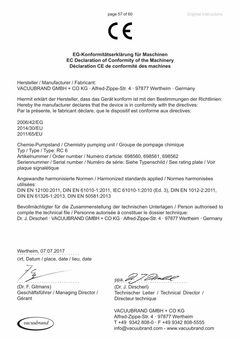
page 57 of 60
EG-Konformitätserklärung für MaschinenEC Declaration of Conformity of the Machinery
Déclaration CE de conformité des machines
Hersteller / Manufacturer / Fabricant: VACUUBRAND GMBH + CO KG · Alfred-Zippe-Str. 4 · 97877 Wertheim · Germany
Hiermit erklärt der Hersteller, dass das Gerät konform ist mit den Bestimmungen der Richtlinien:Hereby the manufacturer declares that the device is in conformity with the directives:Par la présente, le fabricant déclare, que le dispositif est conforme aux directives:
2006/42/EG2014/30/EU2011/65/EU
Chemie-Pumpstand / Chemistry pumping unit / Groupe de pompage chimiqueTyp / Type / Type: RC 6Artikelnummer / Order number / Numéro d‘article: 698560, 698561, 698562Seriennummer / Serial number / Numéro de série: Siehe Typenschild / See rating plate / Voir plaque signalétique
Angewandte harmonisierte Normen / Harmonized standards applied / Normes harmonisées utilisées:DIN EN 12100:2011, DIN EN 61010-1:2011, IEC 61010-1:2010 (Ed. 3), DIN EN 1012-2:2011, DIN EN 61326-1:2013, DIN EN 50581:2013
Bevollmächtigter für die Zusammenstellung der technischen Unterlagen / Person authorised to compile the technical file / Personne autorisée à constituer le dossier technique:Dr. J. Dirscherl · VACUUBRAND GMBH + CO KG · Alfred-Zippe-Str. 4 · 97877 Wertheim · Germany
. . . . . . . . . . . . . . . . . . . . . . . . . . . .(Dr. F. Gitmans)Geschäftsführer / Managing Director / Gérant
. . . . . . . . . . . . . . . . . . . . . . . . . . . . Ort, Datum / place, date / lieu, dateWertheim, 07.07.2017
. . . . . . . . . . . . . . . . . . . . . . . . . . . . . . . . . (Dr. J. Dirscherl)Technischer Leiter / Technical Director / Directeur technique
ppa.
VACUUBRAND GMBH + CO KGAlfred-Zippe-Str. 4 · 97877 WertheimT +49 9342 808-0 · F +49 9342 [email protected] - www.vacuubrand.com
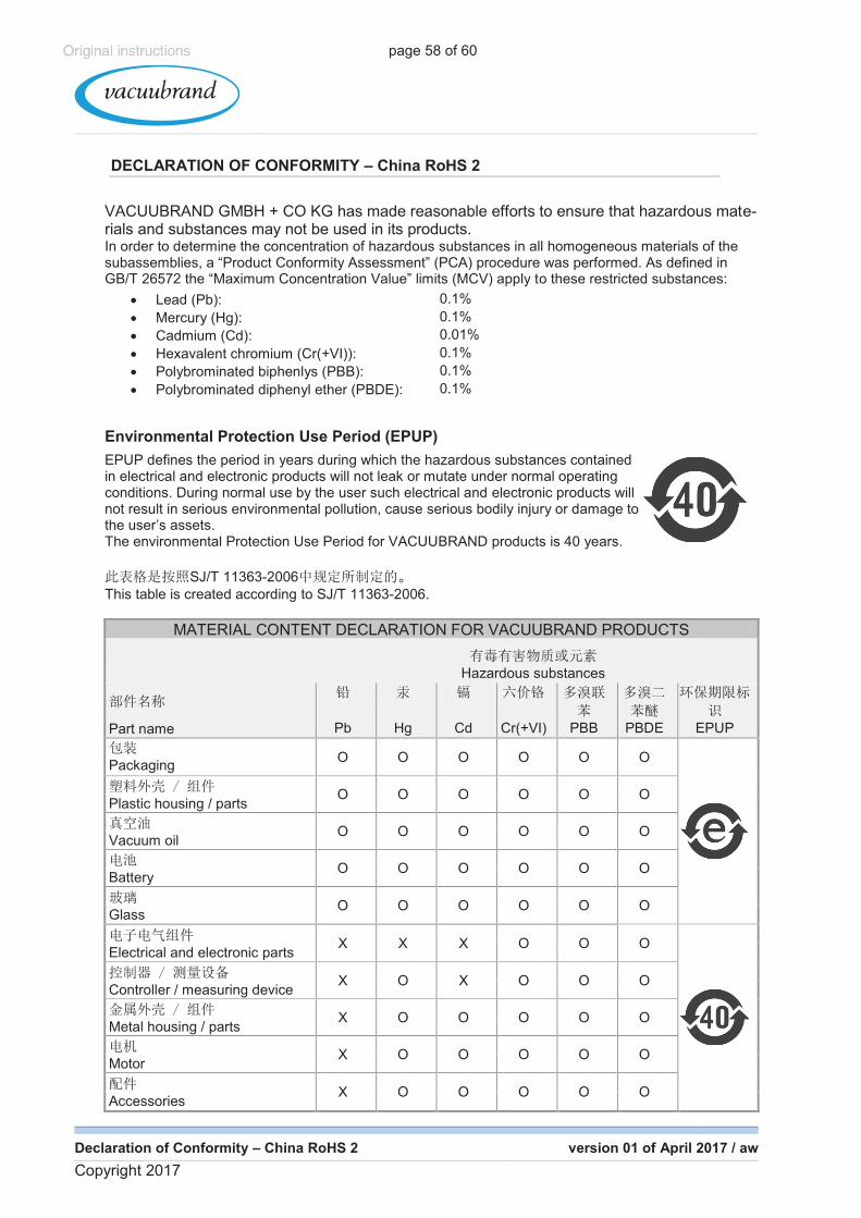
page 58 of 60
Declaration of Conformity – China RoHS 2 version 01 of April 2017 / aw
Copyright 2017
DECLARATION OF CONFORMITY – China RoHS 2
VACUUBRAND GMBH + CO KG has made reasonable efforts to ensure that hazardous mate-rials and substances may not be used in its products. In order to determine the concentration of hazardous substances in all homogeneous materials of the subassemblies, a “Product Conformity Assessment” (PCA) procedure was performed. As defined in GB/T 26572 the “Maximum Concentration Value” limits (MCV) apply to these restricted substances:
� Lead (Pb): 0.1%
� Mercury (Hg): 0.1%
� Cadmium (Cd): 0.01%
� Hexavalent chromium (Cr(+VI)): 0.1%
� Polybrominated biphenlys (PBB): 0.1%
� Polybrominated diphenyl ether (PBDE): 0.1%
Environmental Protection Use Period (EPUP)
EPUP defines the period in years during which the hazardous substances contained in electrical and electronic products will not leak or mutate under normal operating conditions. During normal use by the user such electrical and electronic products will not result in serious environmental pollution, cause serious bodily injury or damage to the user’s assets. The environmental Protection Use Period for VACUUBRAND products is 40 years.
SJ/T 11363-2006
This table is created according to SJ/T 11363-2006.
MATERIAL CONTENT DECLARATION FOR VACUUBRAND PRODUCTS
Hazardous substances
Part name Pb Hg Cd Cr(+VI) PBB PBDE EPUP
Packaging
O O O O O O
Plastic housing / parts O O O O O O
Vacuum oil
O O O O O O
Battery
O O O O O O
Glass
O O O O O O
Electrical and electronic parts
X X X O O O
Controller / measuring device
X O X O O O
Metal housing / parts
X O O O O O
Motor
X O O O O O
Accessories
X O O O O O
China RoHS
page 59 of 60
Declaration of Conformity – China RoHS 2 version 01 of April 2017 / aw
Copyright 2017
Note: Table applies to all products. Some of the components or parts listed above may not be part of the enclosed product.
O:
O: Indicates that the above mentioned hazardous substance contained in all homogeneous mate-rials of the part is below the required limit as defined in GB/T 26572.
X:
X: Indicates that the above mentioned hazardous substance contained in at least one of the ho-mogeneous materials of this part is above the required limit as defined in GB/T 26572.
Pb Hg Cd
Cr(+VI) PBB PBDE
Apart from the disclosures in the above table, the subassemblies are not intentionally manufactured or formulated with lead (Pb), mercury (Hg), cadmium (Cd), hexavalent chromium (Cr+VI), polybrominated biphenyls (PBB), and polybrominated diphenyl ethers (PBDE).
Products manufactured by VACUUBRAND may enter into further devices (e.g., rotary evaporator) or can be used together with other appliances (e.g., usage as booster pumps). With these products and appliances in particular, please note the EFUP labeled on these products. VACUUBRAND will not take responsibility for the EFUP of those products and appliances.
Place, date: Wertheim, 04/24/2017
ppa.
(Dr. F. Gitmans) (Dr. J. Dirscherl)
Managing Director Technical Director
VACUUBRAND GMBH + CO KG Tel.: +49 9342 808-0
Alfred-Zippe-Str. 4 Fax: +49 9342 808-5555
97877 Wertheim E-Mail: [email protected]
Germany Web: www.vacuubrand.com
page 60 of 60
Disclaimer: Our technical literature is only intended to inform our cus-tomer. The applicability of general empirical values and results obtained under lab conditions to your specific operations depends on a number of factors beyond our control. It is, therefore, strictly the users’ responsibil-ity to very carefully check the application of these data to their specific requirements. No claims arising from the information provided in this lit-erature will, consequently, be be entertained.
VACUUBRAND GMBH + CO KG- Technology for Vacuum Systems -© 2017 VACUUBRAND GMBH + CO KG Printed in Germany
Manual-no.: 997829 / 07/07/2017
Alfred-Zippe-Str. 4 · 97877 Wertheim / GermanyT +49 9342 808-0 · F +49 9342 808-5555
[email protected] · www.vacuubrand.com