Embed Size (px)
Citation preview

Technologies OverviewTechnology description & application examples by currENT members
2
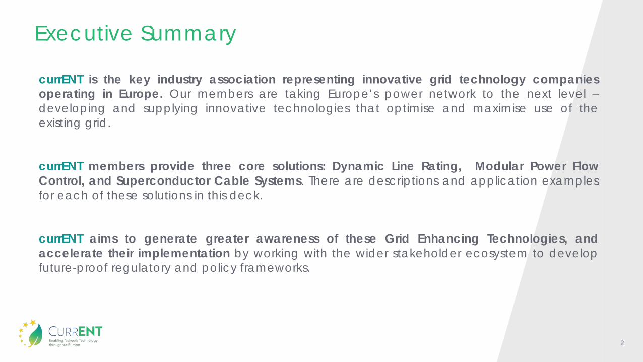
currENT is the key industry association representing innovative grid technology companiesoperating in Europe. Our members are taking Europe’s power network to the next level –developing and supplying innovative technologies that optimise and maximise use of theexisting grid.
currENT members provide three core solutions: Dynamic Line Rating, Modular Power FlowControl, and Superconductor Cable Systems. There are descriptions and application examplesfor each of these solutions in this deck.
currENT aims to generate greater awareness of these Grid Enhancing Technologies, andaccelerate their implementation by working with the wider stakeholder ecosystem to developfuture-proof regulatory and policy frameworks.
Executive Summary

3
Contents1. Introduction to currENT
2. Dynamic Line Rating
3. Modular Power Flow Control Solutions
4. Superconductor Cable Systems
4
Introduction to currENT“Our Vision is a European power network that is the recognised world
leader in enabling decarbonisation through the efficient use of modern grid technology”
5
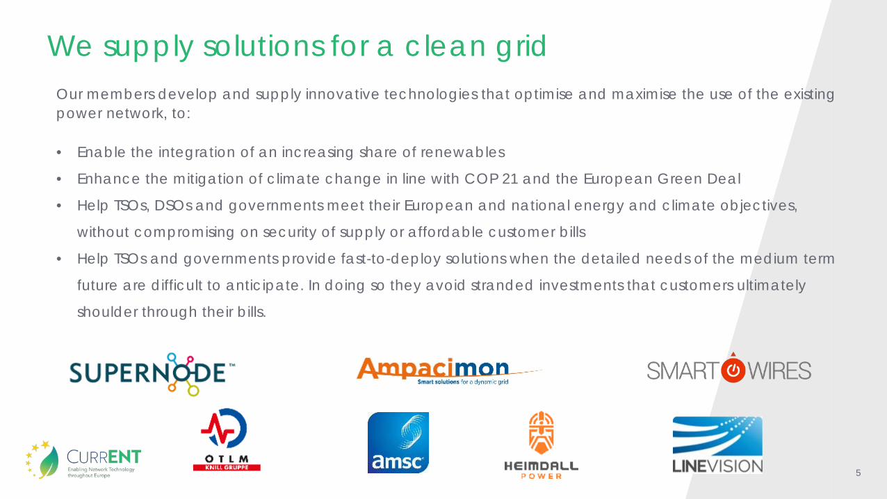
Our members develop and supply innovative technologies that optimise and maximise the use of the existing power network, to:
• Enable the integration of an increasing share of renewables
• Enhance the mitigation of climate change in line with COP 21 and the European Green Deal
• Help TSOs, DSOs and governments meet their European and national energy and climate objectives,
without compromising on security of supply or affordable customer bills
• Help TSOs and governments provide fast-to-deploy solutions when the detailed needs of the medium term
future are difficult to anticipate. In doing so they avoid stranded investments that customers ultimately
shoulder through their bills.
We supply solutions for a clean grid
6
Our ObjectivescurrENT member companies are driven by a common goal – to speed up the green energy transition.
We want to see Renewables take up massively, climate change mitigated successfully, while security of supply is kept high and costs kept low. We see power networks at the core of, and as the basis for, a successful energy transition.
We achieve our common goal through the following actions:
1
2
3
4
Generate awareness – of new grid enhancing technologies, the opportunities and challenges, and increasing awareness of the benefits of new technology. We wish to bring new game changing solutions to the table.Move policy – we contribute to future-proof regulatory frameworks that speed up the adoption of alternative proven solutions for the benefit of all Europeans.Enhance technology – we introduce, and where needed, trial new technologies; learning from each other through European benchmarking.Engage – in acting collectively through our association we stand up for the principles of transparency and stakeholder interaction.

7
Dynamic Line Rating
8
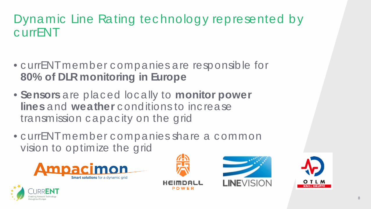
Dynamic Line Rating technology represented by currENT
• currENT member companies are responsible for 80% of DLR monitoring in Europe
• Sensors are placed locally to monitor power lines and weather conditions to increase transmission capacity on the grid
• currENT member companies share a common vision to optimize the grid
9
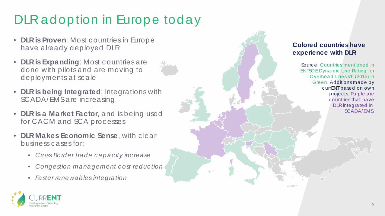
DLR adoption in Europe today• DLR is Proven: Most countries in Europe
have already deployed DLR
• DLR is Expanding: Most countries are done with pilots and are moving to deployments at scale
• DLR is being Integrated: Integrations with SCADA/EMS are increasing
• DLR is a Market Factor, and is being used for CACM and SCA processes
• DLR Makes Economic Sense, with clear business cases for:
• Cross Border trade capacity increase
• Congestion management cost reduction
• Faster renewables integration
Colored countries have experience with DLR
Source: Countries mentioned in ENTSOE Dynamic Line Rating for
Overhead Lines V6 (2015) in Green. Additions made by
currENT based on own projects. Purple are countries that have
DLR integrated inSCADA/EMS.
10
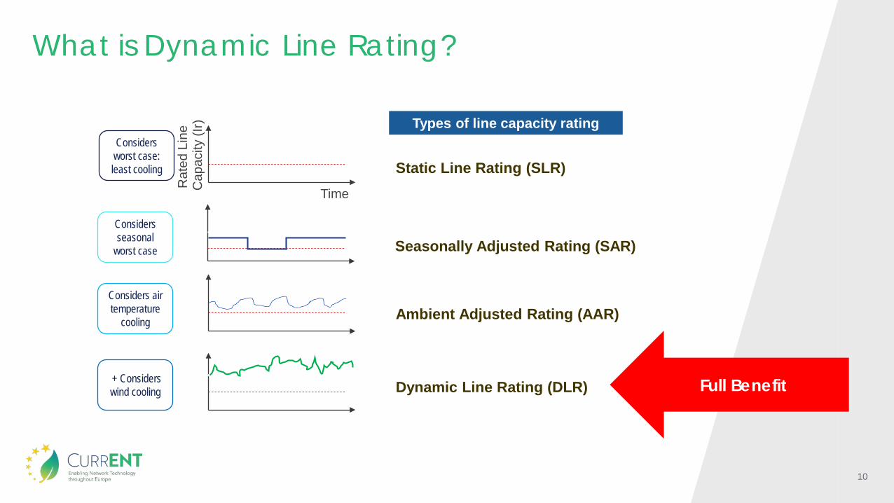
What is Dynamic Line Rating?
Dynamic Line Rating (DLR)+ Considers wind cooling
Ambient Adjusted Rating (AAR)Considers air temperature
cooling
Static Line Rating (SLR)R
ated
Lin
e C
apac
ity (I
r)Time
Considers worst case: least cooling
Types of line capacity rating
Full Benefit
Seasonally Adjusted Rating (SAR)Considers seasonal
worst case
11
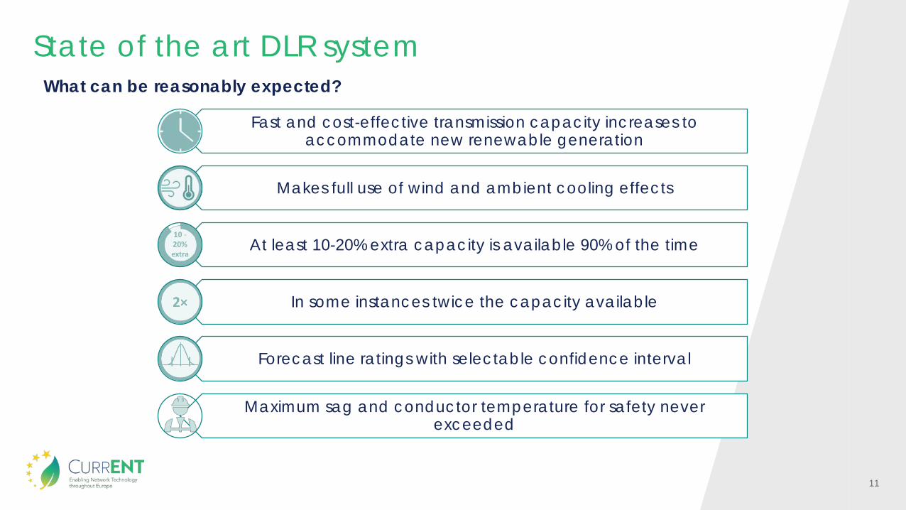
State of the art DLR system
Fast and cost-effective transmission capacity increases to accommodate new renewable generation
Makes full use of wind and ambient cooling effects
At least 10-20% extra capacity is available 90% of the time
In some instances twice the capacity available
Forecast line ratings with selectable confidence interval
Maximum sag and conductor temperature for safety never exceeded
What can be reasonably expected?

12
Applications and benefits
Saved 500 kEUR
redispatch costs in a day
10-20% increase in
acceptable infeed
Saved 247 kEUR in 4 hours
• Congestion management costs range from 20-500EUR/MWh
• Expensive measures used to address moderate (~10%) overloads.
Reduce congestion management costs
•Making full use of ambient cooling effect, transmission lines can be used to transport energy more efficiently
•Maximum sag and conductor temperature for safety never exceeded
Economic dispatch cost reduction
•Short-term solution to boost market coupling capacity.
•Small capacity increase in high price split reap enormous returns in short time frame.
•Cross border capacity benefits all citizens.
Increase cross-border trade capacity
①
②
③
13
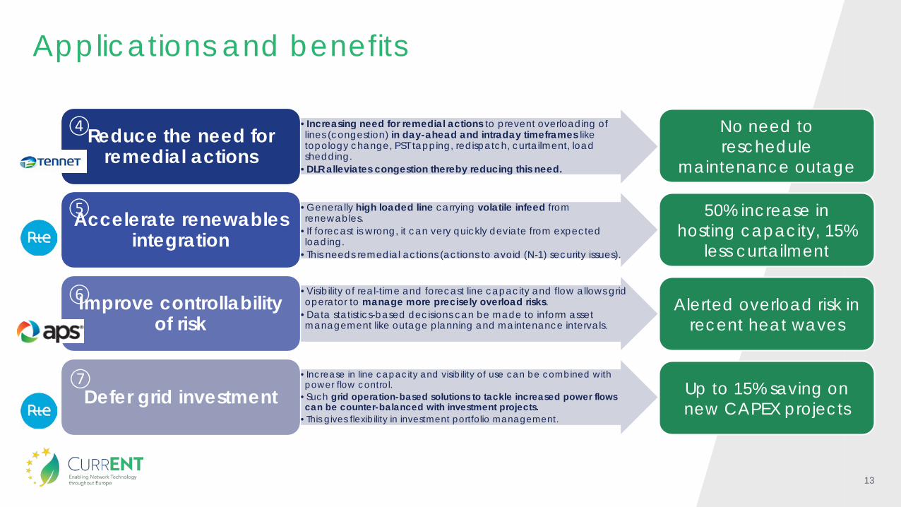
Applications and benefits
•Increasing need for remedial actions to prevent overloading of lines (congestion) in day-ahead and intraday timeframes like topology change, PST tapping, redispatch, curtailment, load shedding.
•DLR alleviates congestion thereby reducing this need.
Reduce the need for remedial actions
•Generally high loaded line carrying volatile infeed from renewables.
•If forecast is wrong, it can very quickly deviate from expected loading.
•This needs remedial actions (actions to avoid (N-1) security issues).
Accelerate renewables integration
•Visibility of real-time and forecast line capacity and flow allows grid operator to manage more precisely overload risks.
•Data statistics-based decisions can be made to inform asset management like outage planning and maintenance intervals.
Improve controllability of risk
•Increase in line capacity and visibility of use can be combined with power flow control.
•Such grid operation-based solutions to tackle increased power flows can be counter-balanced with investment projects.
•This gives flexibility in investment portfolio management.
Defer grid investment
No need to reschedule
maintenance outage
50% increase in hosting capacity, 15%
less curtailment
Alerted overload risk in recent heat waves
Up to 15% saving on new CAPEX projects
⑦
④
⑤
⑥

14
Modular Power Flow Control Solutions
15
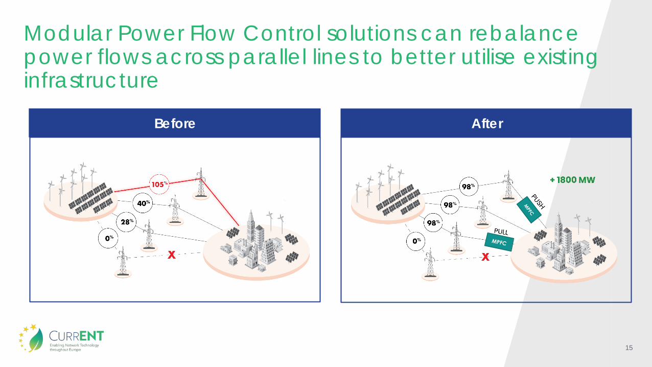
Before
Modular Power Flow Control solutions can rebalance power flows across parallel lines to better utilise existing infrastructure
After
16
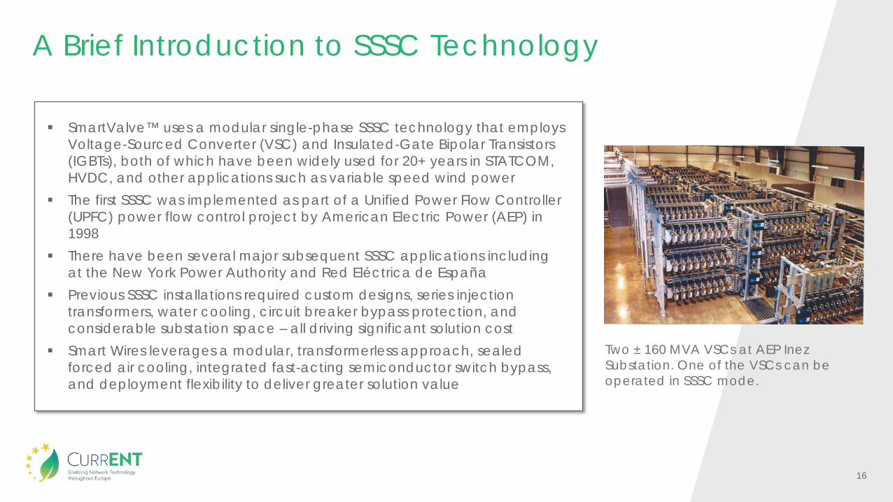
A Brief Introduction to SSSC Technology
SmartValve™ uses a modular single-phase SSSC technology that employs Voltage-Sourced Converter (VSC) and Insulated-Gate Bipolar Transistors (IGBTs), both of which have been widely used for 20+ years in STATCOM, HVDC, and other applications such as variable speed wind power
The first SSSC was implemented as part of a Unified Power Flow Controller (UPFC) power flow control project by American Electric Power (AEP) in 1998
There have been several major subsequent SSSC applications including at the New York Power Authority and Red Eléctrica de España
Previous SSSC installations required custom designs, series injection transformers, water cooling, circuit breaker bypass protection, and considerable substation space – all driving significant solution cost
Smart Wires leverages a modular, transformerless approach, sealed forced air cooling, integrated fast-acting semiconductor switch bypass, and deployment flexibility to deliver greater solution value
Two ± 160 MVA VSCs at AEP Inez Substation. One of the VSCs can be operated in SSSC mode.
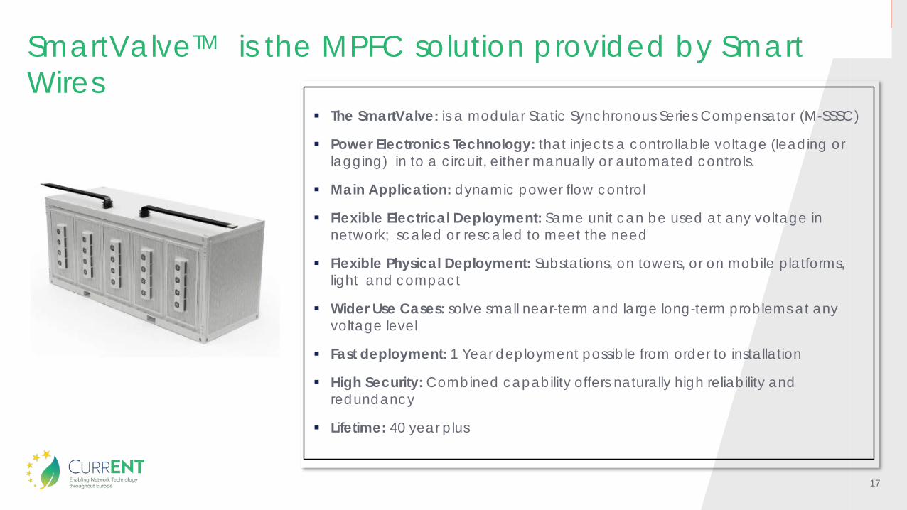
17
The SmartValve: is a modular Static Synchronous Series Compensator (M-SSSC)
Power Electronics Technology: that injects a controllable voltage (leading or lagging) in to a circuit, either manually or automated controls.
Main Application: dynamic power flow control
Flexible Electrical Deployment: Same unit can be used at any voltage in network; scaled or rescaled to meet the need
Flexible Physical Deployment: Substations, on towers, or on mobile platforms, light and compact
Wider Use Cases: solve small near-term and large long-term problems at any voltage level
Fast deployment: 1 Year deployment possible from order to installation
High Security: Combined capability offers naturally high reliability andredundancy
Lifetime: 40 year plus
SmartValveTM is the MPFC solution provided by Smart Wires
18
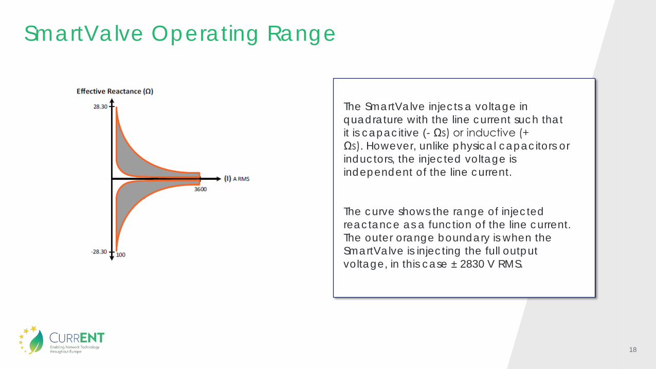
SmartValve Operating Range
The SmartValve injects a voltage in quadrature with the line current such that it is capacitive (- Ωs) or inductive (+ Ωs). However, unlike physical capacitors or inductors, the injected voltage is independent of the line current.
The curve shows the range of injected reactance as a function of the line current. The outer orange boundary is when the SmartValve is injecting the full output voltage, in this case ± 2830 V RMS.
19
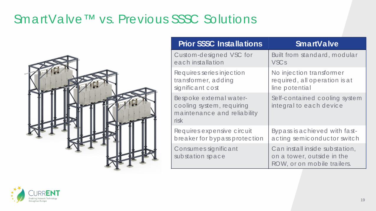
SmartValve™ vs. Previous SSSC Solutions
Prior SSSC Installations SmartValveCustom-designed VSC for each installation
Built from standard, modular VSCs
Requires series injection transformer, adding significant cost
No injection transformer required, all operation is at line potential
Bespoke external water-cooling system, requiring maintenance and reliability risk
Self-contained cooling system integral to each device
Requires expensive circuit breaker for bypass protection
Bypass is achieved with fast-acting semiconductor switch
Consumes significant substation space
Can install inside substation, on a tower, outside in the ROW, or on mobile trailers.
20
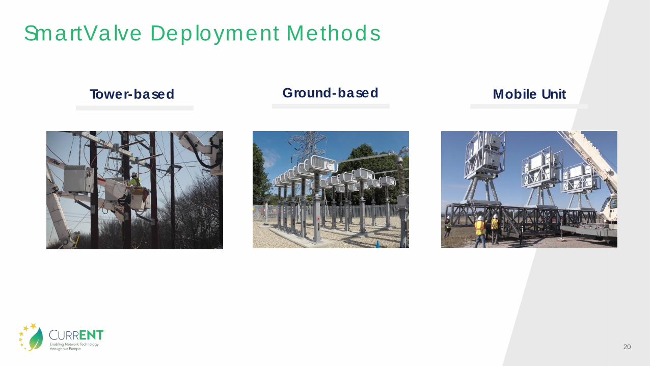
SmartValve Deployment Methods
Tower-based Ground-based Mobile Unit

21
The Added Value of Modular Power Flow Control SolutionsMinimized Risk of Long Term InvestmentParticularly important when considering future projects where need arises in a small number of scenarios and where there is uncertainty as to when the need will materialize.
RedeployabilitySmartValves are designed to be re-deployable to another area of the network if a greater need materializes.
Flexibility in Installation and Control SmartValves can be installed on existing towers or within the substation environment. The substation deployment is designed to be as compact as possible.
Modularity and ScalabilityThe solution can be scaled up or down if the need materializes or changes in the future, particularly where a need is driven by new generation.
Fast Delivery & Installation SmartValve solutions can be installed in less time than traditional options. In many cases, this means that a solution can be installed in less than 1 year.
No Single Point of Failure As the devices are modular, the failure of a single device as opposed to the entire solution such as a series reactor/PST means that the transmission owner has greater security with a SmartValve solution.
22
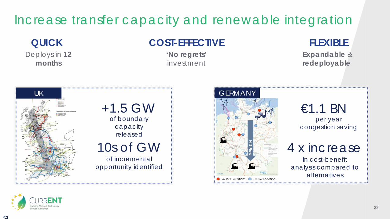
Increase transfer capacity and renewable integration
Sl
+1.5 GWof boundary
capacity released
10s of GWof incremental
opportunity identified
Deploys in 12 months
‘No regrets’ investment
Expandable & redeployable
QUICK COST-EFFECTIVE FLEXIBLE
€1.1 BNper year
congestion saving
4 x increaseIn cost-benefit
analysis compared to alternatives
UK GERMANY
23
Superconductor Cable Systems
24
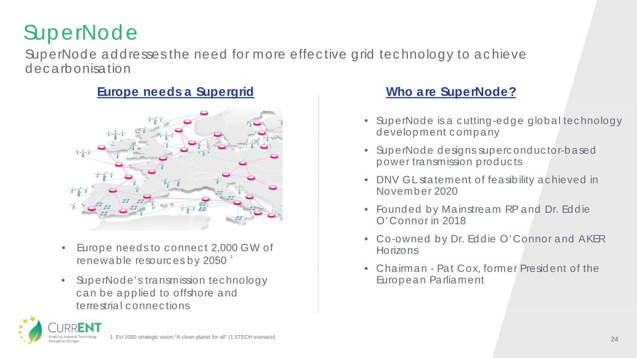
SuperNodeSuperNode addresses the need for more effective grid technology to achieve decarbonisation
• SuperNode is a cutting-edge global technology development company
• SuperNode designs superconductor-based power transmission products
• DNV GL statement of feasibility achieved in November 2020
• Founded by Mainstream RP and Dr. Eddie O’Connor in 2018
• Co-owned by Dr. Eddie O’Connor and AKER Horizons
• Chairman - Pat Cox, former President of the European Parliament
• Europe needs to connect 2,000 GW of renewable resources by 2050
1. EU 2050 strategic vision “A clean planet for all” (1.5TECH scenario)
• SuperNode’s transmission technology can be applied to offshore and terrestrial connections
1
Who are SuperNode?Europe needs a Supergrid
25
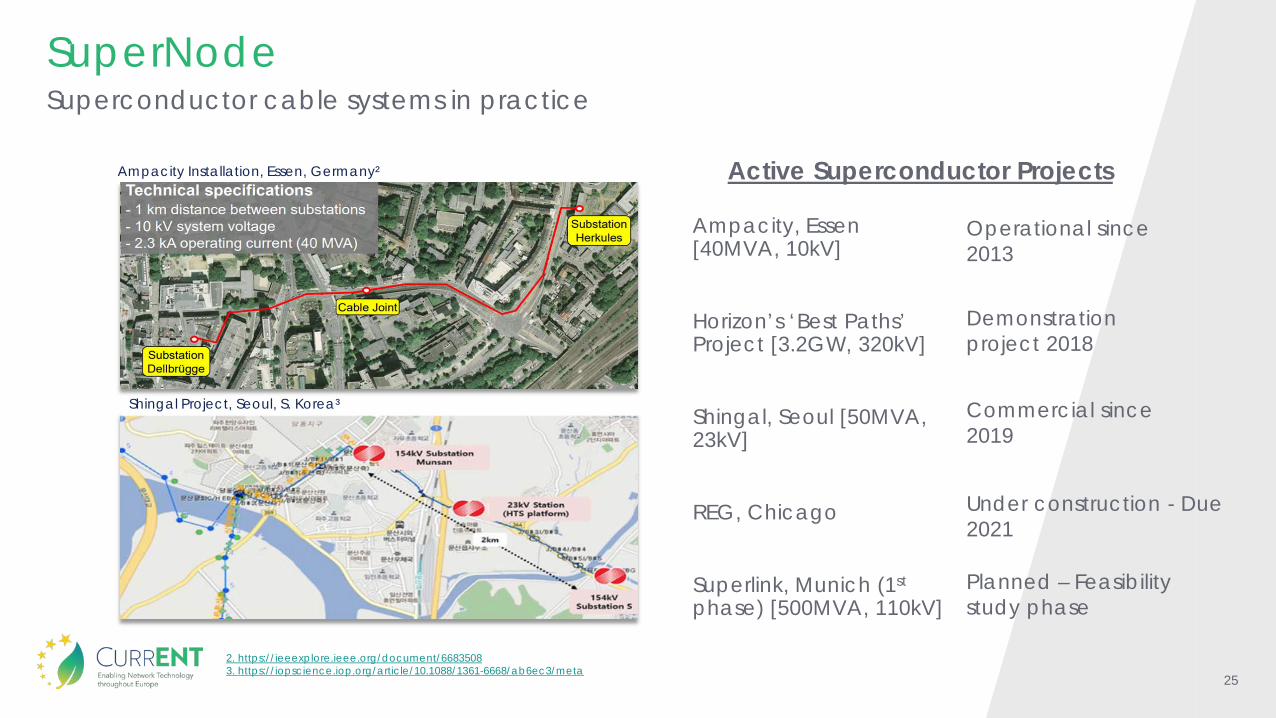
SuperNode
Ampacity, Essen [40MVA, 10kV]
Horizon’s ‘Best Paths’ Project [3.2GW, 320kV]
Shingal, Seoul [50MVA, 23kV]
REG, Chicago
Superlink, Munich (1st
phase) [500MVA, 110kV]
Ampacity Installation, Essen, Germany²
Shingal Project, Seoul, S. Korea³
Operational since 2013
Commercial since 2019
Under construction - Due 2021
Planned – Feasibility study phase
Demonstration project 2018
2. https://ieeexplore.ieee.org/document/66835083. https://iopscience.iop.org/article/10.1088/1361-6668/ab6ec3/meta
Active Superconductor Projects
Superconductor cable systems in practice
26
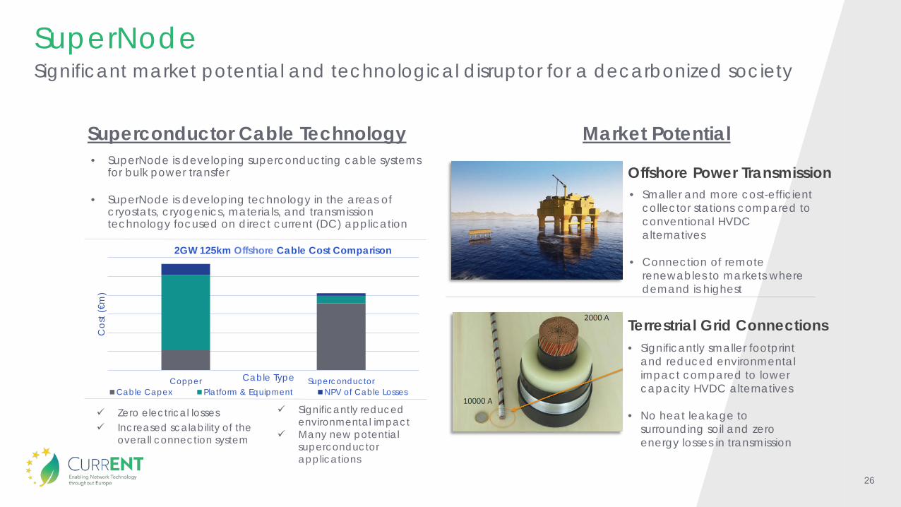
SuperNode
Offshore Power Transmission• Smaller and more cost-efficient
collector stations compared to conventional HVDC alternatives
• Connection of remote renewables to markets where demand is highest
• Significantly smaller footprint and reduced environmental impact compared to lower capacity HVDC alternatives
• No heat leakage to surrounding soil and zero energy losses in transmission
Terrestrial Grid Connections
• SuperNode is developing superconducting cable systems for bulk power transfer
• SuperNode is developing technology in the areas of cryostats, cryogenics, materials, and transmission technology focused on direct current (DC) application
Copper Superconductor
Cos
t (€m
)
Cable Type
2GW 125km Offshore Cable Cost Comparison
Cable Capex Platform & Equipment NPV of Cable Losses
Significantly reduced environmental impact
Many new potential superconductor applications
Zero electrical losses Increased scalability of the
overall connection system
Market PotentialSuperconductor Cable Technology
Significant market potential and technological disruptor for a decarbonized society

27
SuperNode
“Regarding HVDC cables, recurring to superconductivity technologies and namely High Temperature Cables (HTC) may be technically and economically convenient when the increase of transmission capacity need over a corridor requests the addition of more cables in parallel - It would be beneficial to develop HTC technologies for Superconducting Transmission Lines (STL) to explore its potential in situations where very high amounts of power need to be transmitted”(…)“to build the offshore energy production, and its connection to onshore consumption, an interconnected grid is needed”
“By its very nature, renewable electricity will be cheaper than zero-carbon hydrogen (which is a vector that stores renewable electricity). In the view of the authors, this gives rise to possibly the most important conclusion from this study. Aside from energy efficiency, the most important and immediate priority for the EU in ensuring a cost-effective decarbonisation of its energy system must therefore be to identify and eliminate infrastructure and other bottlenecks that are likely to constrain the cost-effective production and use of renewable electricity moving forwards”
“In Best Paths, gigawatt-scale superconducting cables were investigated and shown to be technologically mature and cost-competitive for the transmission of large amounts of electricity. Thanks to their high efficiency, compact size, and reduced environmental impact, superconducting cables are likely to find higher public acceptance than overhead lines and conventional cables”
Best Paths, “Advancing Superconducting links for very high-power transmission” 2018
Florence School of Regulation: A. Piebalgs, fmr. European Commissioner for Energy, C. Jones, fmr. Head of Cabinet, DG Energy, European Commission, “Cost-Effective Decarbonisation Study” 2020
European Commission, “Clean Energy Transition – technologies and innovations. (CET-TIR)” 2020
“Superconductors will do for electricity what fibre optic cables did for telecoms by replacing the twisted pair”
Pat Cox, SuperNode Chairman and former President of the European Parliament
An expert perspective on superconductors