Embed Size (px)
Citation preview
Technologies for Protection and Resistance Enhancement
Critical Infrastructures against Extreme Fire Prepared by: Hossein Mostafaei Mohamed Sultan Ahmed Kashef National Research Council of Canada
Scientific Authority: Pierre Meunier DRDC Centre for Security Science The scientific or technical validity of this Contract Report is entirely the responsibility of the Contractor and the contents do not necessarily have the approval or endorsement of the Department of National Defence of Canada.
DRDC-RDDC-2014-C
May 2014
IMPORTANT INFORMATIVE STATEMENTS CSSP-2013-CD-1073 Technologies for Protection and Resistance Enhancement of Critical Infrastructures against Extreme Fires was supported by the Canadian Safety and Security Program (CSSP) which is led by Defence Research and Development Canada’s Centre for Security Science, in partnership with Public Safety Canada. Partners in the project include National Research Council, Transport Canada, and Industry Canada. CSSP is a federally-funded program to strengthen Canada’s ability to anticipate, prevent/mitigate, prepare for, respond to, and recover from natural disasters, serious accidents, crime and terrorism through the convergence of science and technology with policy, operations and intelligence
© Her Majesty the Queen in Right of Canada, as represented by the Minister of National Defence, 2014
© Sa Majesté la Reine (en droit du Canada), telle que représentée par le ministre de la Défense nationale, 2014
NATIONAL RESEARCH COUNCIL CANADA Technologies For Protection and Resistance Enhancement of Critical Infrastructures against Extreme Fire Technologies pour la protection des infrastructures essentielles et l’amélioration de leur résistance aux conditions d’incendie extrêmes
Hossein Mostafaei, Mohamed Sultan, and Ahmed Kashef
March 31, 2014
2 CSSP-2013-CD-1073
Abstract ……..
This report provides information that could help shape national approaches for emerging risk mitigation of extreme fire threats to critical infrastructures (CIs). The results include mitigation technologies and information for fire protection and resistance enhancement of structures.
The objective of this study was to review available fire protection materials and technologies for protection application to critical infrastructures and to identify materials and technologies that would be potential solutions for the protection of critical infrastructures against threats of extreme fires.
The approach used in this study includes: First, a list of available fire protection technologies and materials, mainly passive fire protection such as spray applied materials and intumescent coating, was established as potential solutions for application in critical infrastructures, e.g. bridges, tunnels, important buildings and facilities against extreme fires. Second, the identified fire protection solutions were reviewed for the required performance criteria of CIs in extreme fire conditions. Finally, based on the review results, potential protection solutions were recommended for CIs e.g. bridges and buildings, against extreme fires. The recommended solutions for this study are based on a review assessment. Future experimental studies are needed to confirm that the recommended solutions could perform as expected in a simulated extreme fire environment. The outcome of this study is expected to provide the critical infrastructure community of practice with information on potential effective protection solutions for CIs against extreme fires.
This report presents the outcomes of the review, identifications and recommendations of potential solutions for extreme fire protection of critical infrastructures.
Résumé ….....
Le présent rapport fournit de l’information qui pourrait aider à élaborer des démarches nationales pour une atténuation du risque émergeant des conditions d’incendie extrêmes pour les infrastructures essentielles (IE). Les résultats comprennent les technologies d’atténuation et l’information rattachée à la protection contre l’incendie et à l’amélioration de la résistance des structures.
Cette étude avait pour objectifs d’examiner les matériaux et les technologies de protection contre l’incendie qui sont disponibles pour application aux IE, et d’identifier les matériaux et les technologies qui pourraient constituer des solutions potentielles au problème de la protection des IE contre les menaces de conditions d’incendie extrêmes.
Voici la démarche utilisée dans le cadre de cette étude. En un premier temps, on a dressé une liste de technologies et de matériaux de protection contre l’incendie déjà disponibles, essentiellement une protection passive contre l’incendie comme les substances pulvérisées et les revêtements intumescents, comme autant de solutions potentielles pour fin d’application aux IE, c.-à-d. aux ponts, aux tunnels, aux bâtiments importants et aux installations, et de leur protection contre les conditions d’incendie extrêmes. Dans un deuxième temps, les solutions de protection identifiées ont été examinées en regard des critères de performance requis des IE en conditions d’incendie extrêmes. Enfin, sur la base des résultats de l’examen, des solutions de protection potentielles ont été recommandées pour les IE, soit les ponts et les bâtiments, face aux conditions d’incendie extrêmes. Les solutions recommandées relativement à cette étude sont fondées sur une étude

3 CSSP-2013-CD-1073
analytique. Des études expérimentales seront requises éventuellement pour confirmer que les solutions recommandées pourraient donner le rendement escompté dans un environnement d’incendie extrême simulé. On s’attend à ce que les conclusions de cette étude procurent au réseau d’échange de pratiques des IE de l’information sur les solutions efficaces potentielles pour protéger celles-ci contre les conditions d’incendie extrêmes.
Le présent rapport expose les conclusions de l’examen, des identifications et des recommandations de solutions potentielles pour la protection des IE contre les incendies extrêmes.
4 CSSP-2013-CD-1073
Executive summary
Background: Recently, as part of a Canadian Safety and Security Program project, NRC carried out a study on Resilience of Critical Infrastructure to Extreme Fires – Gaps and Challenges, which was completed in March 2013 [1]. The results of that study showed the critical infrastructures such as bridges, tunnels, and buildings are vulnerable to extreme fires. One of the gaps was the need to identify potential solutions for fire protection of critical Infrastructures against extreme fires. Consequently, through the Canadian Safety and Security Program, NRC carried out a study to fill this gap. This report provides the results of this study.
At present, critical infrastructures such as bridges, e.g. those at the port of entry, or critical buildings, government buildings, embassies, are not usually designed for protection in extreme fire events, e.g. fuel tanker fire. The threat of a deliberate extreme fire event against a critical infrastructure is readily perceptible. There are already several reports of accidental fuel tanker fires resulting in complete collapse of critical infrastructures (CIs), such as bridges, tunnels, or buildings. This indicates that CIs could be very vulnerable to such a threat, either deliberate or accidental. Currently, there are fire protection technologies and materials for facilities such as oil refineries and offshore structures against extreme fires. There have also been studies on enhancing fire resistance and protection of tunnels, e.g. developing new concrete mix design or fire protection materials for enhancing resistance of the tunnels against extreme fires. This study reviewed these common solutions as well as those currently used for fire protection of buildings against normal fire to identify potential solutions that could be employed and studied further for protection of critical infrastructures, e.g. bridges and buildings, against extreme fires.
There are different fire protection technologies applicable for different types of structures including active and passive fire protections. Active fire protections, e.g. sprinkler systems, foam application system and detectors, require a certain amount of heat or smoke in order to work. However, passive fire protections are integrated within the infrastructures. Their main role of either the active or passive fire protection is to prevent fire spread and to reduce the risk of structural collapse. The main focus of this study is on passive fire protections, as identified by the gap analysis.
Critical infrastructures are facilities which their function is vital to the society and economy. Therefore, in addition to ensure life safety, which is always a main requirement for providing fire safety, property protection and fast recovery of the critical infrastructure after an incident, e.g. extreme fire, is very essential to minimize the social and economic impacts on the community. Therefore, one of the unique requirements for fire protection of critical infrastructure would be to not only prevent structural collapse but also to minimize the structural damage during extreme fires.
The main goal of this study was to identify potential technologies, e.g. materials or systems, for protection of critical infrastructures against extreme fires to meet these requirements.
Results: The results of this project could be summarized in two main items as follows:
1) Available passive fire protection materials and technologies, e.g. built-in fire protections and exterior fire protections, are identified and listed.
5 CSSP-2013-CD-1073
2) The identified fire protection materials and technologies were reviewed based on the criteria that would be required for critical infrastructures, e.g. severe weather exposure for bridges. Those with potential to meet the performance criteria were selected and recommended for protection of CIs. Future experimental studies need to be carried out to confirm the expected performances in a simulated extreme fire environment.
Significance: The outcomes of this project are expected to provide the critical infrastructure community of practice with information on the potential protection solutions to help improvement of resiliency of the Critical Infrastructures to extreme fire events. Suitable extreme fire protection technologies could be employed to enhance life safety, reduce structural damage and minimize the recovery time for critical infrastructures during and after extreme fire events.
Future plans: The outcome of this study can be used to extend the recommended extreme fire protection materials and technologies to the demonstration level. Future plan is to develop research proposal and perform studies to evaluate the recommended technologies and materials using the required experimentation for demonstration purposes. The materials and technologies that pass the tests will be ready to be employed in practice.

6 CSSP-2013-CD-1073
Sommaire .....
Contexte : Récemment, dans le cadre d’un projet du Programme canadien pour la sûreté et la sécurité, le CNRC a réalisé une étude portant sur la résilience des infrastructures essentielles (IE) en conditions d’incendie extrêmes (Resilience of Critical Infrastructure to Extreme Fires – Gaps and Challenges), terminée en mars 2013 [1]. Les résultats de cette étude ont révélé que les IE telles que les ponts, les tunnels et les bâtiments sont vulnérables en conditions d’incendie extrêmes. L’une des lacunes identifiées était le besoin de trouver des solutions potentielles en matière de protection des IE en conditions d’incendie extrêmes. Ainsi, par le biais du Programme canadien pour la sûreté et la sécurité, le CNRC a réalisé une étude afin de combler cette lacune. Le présent rapport fournit les résultats de cette étude.
À l’heure actuelle, les IE comme les ponts, par exemple ceux des points d’entrée, et les bâtiments essentiels, les bâtiments gouvernementaux et les ambassades, ne sont pas conçus normalement pour être protégés en conditions d’incendie extrêmes, par exemple au cours d’un incendie de véhicule-citerne. Il est facile de se représenter l’ampleur de la menace d’un acte incendiaire extrême commis délibérément contre une IE. Plusieurs rapports font état d’incendies accidentels causés par des véhicules-citernes ayant eu pour résultat l’effondrement complet d’IE comme des ponts, des tunnels ou des bâtiments. Ceci indique à quel point les IE peuvent être vulnérables à de pareilles menaces, qu’elles soient accidentelles ou délibérées. Il existe déjà des technologies et des matériaux de protection contre les conditions d’incendie extrêmes pour les installations comme les raffineries de pétrole et les constructions en mer. Des études se sont également intéressées à l’amélioration de la résistance au feu et de la protection des tunnels, soit par la mise au point de nouveaux mélanges pour composition du béton ou matériaux ignifuges améliorant la résistance des tunnels aux conditions d’incendie extrêmes. On se penche dans ces études sur les solutions courantes ainsi que sur celles déjà employées aux fins de la protection des bâtiments contre les incendies ordinaires, en vue d’identifier les approches potentielles qui pourraient être retenues et explorées plus à fond pour la protection des IE, c.-à-d. les ponts et bâtiments, contre les conditions d’incendie extrêmes.
Il existe différentes technologies de protection contre l’incendie, applicables à autant de types de structures différents, incluant la protection active et la protection passive. Le fonctionnement des systèmes de protection active contre l’incendie, soit les réseaux de gicleurs, les systèmes d’extinction par mousse et les détecteurs, doit être déclenché par une certaine quantité de chaleur ou de fumée. Quant aux technologies de protection passive, elles se trouvent intégrées à l’intérieur des infrastructures. Le rôle principal de la protection active comme passive est d’empêcher le feu de s’étendre et de réduire le risque d’effondrement des structures. La présente étude s’intéresse principalement aux technologies de protection passive contre les incendies, telles qu’identifiées par l’analyse des lacunes.
Les IE sont des installations dont la fonction est vitale pour la société et l’économie. Par conséquent, en plus d’assurer la sécurité des personnes, ce qui est toujours l’exigence prioritaire de la sécurité incendie, la protection des biens et la prompte remise en service de l’IE après un incident, en l’occurrence un incendie extrême, demeurent essentielles pour réduire au minimum les impacts sociaux et économiques pour la collectivité desservie. Ainsi, l’une des exigences particulières de la protection des IE serait de prévenir l’effondrement des structures, mais aussi de réduire au minimum les dommages structurels en conditions d’incendie extrêmes.
L’objectif principal de la présente étude était d’identifier les technologies potentielles, les matériaux ou les systèmes, pour la protection des IE contre les conditions d’incendie extrêmes et ce, afin de satisfaire à ces exigences.
7 CSSP-2013-CD-1073
Résultats : Les résultats du présent projet pourraient être résumés en deux (2) volets principaux :
1) Les matériaux et technologies de protection passive contre l’incendie qui sont déjà disponibles, soit la protection incorporée et la protection extérieure contre les incendies, sont identifiés et répertoriés.
2) Les matériaux et technologies de protection contre l’incendie identifiés ont été examinés sur la base des critères qui seraient requis pour les IE, soit l’exposition à des conditions météorologiques rigoureuses dans le cas des ponts. Des matériaux et technologies ayant le potentiel de satisfaire aux critères de performance ont été sélectionnés et recommandés pour la protection des IE. Des études expérimentales devront être réalisées à l’avenir pour confirmer les performances escomptées dans un environnement d’incendie extrême simulé.
Pertinence : On s’attend à ce que les conclusions du présent projet fournissent au réseau d’échange des pratiques des IE de l’information sur les solutions potentielles en matière de protection, qui aidera à améliorer la résilience des IE en conditions d’incendie extrêmes. Des technologies de protection adéquates contre les incendies extrêmes pourraient être employées aux fins de l’amélioration de la sécurité des personnes, de la diminution des dommages aux structures et de la réduction au minimum du temps de remise en service des IE au cours des événements de type incendie extrême et après ceux-ci.
Prospective : Les résultats de la présente étude peuvent servir à étendre au niveau de la démonstration les matériaux et technologies recommandés pour fin de protection contre les incendies extrêmes. La prospective consistera à élaborer des projets de recherche et à réaliser des études visant à évaluer les technologies et matériaux recommandés en utilisant le type d’expérimentation requis aux fins de la démonstration. Les matériaux et les technologies qui subiront la mise à l’essai avec succès seront prêts à être employés dans la pratique.
8 CSSP-2013-CD-1073
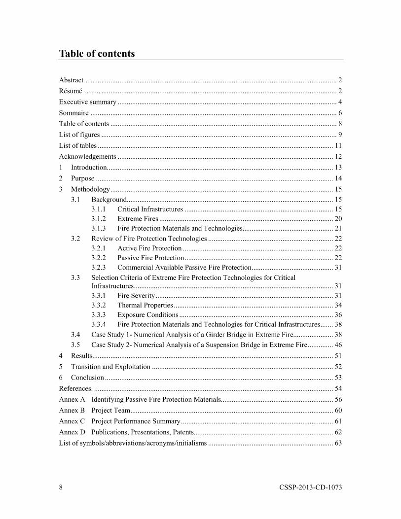
Table of contents
Abstract …….. ................................................................................................................................ 2 Résumé …..... .................................................................................................................................. 2 Executive summary ......................................................................................................................... 4 Sommaire ..... ................................................................................................................................... 6 Table of contents ............................................................................................................................. 8 List of figures .................................................................................................................................. 9 List of tables .................................................................................................................................. 11 Acknowledgements ....................................................................................................................... 12 1 Introduction ............................................................................................................................. 13 2 Purpose ................................................................................................................................... 14 3 Methodology ........................................................................................................................... 15
3.1 Background.................................................................................................................. 15 3.1.1 Critical Infrastructures .................................................................................. 15 3.1.2 Extreme Fires ................................................................................................ 20 3.1.3 Fire Protection Materials and Technologies .................................................. 21
3.2 Review of Fire Protection Technologies ..................................................................... 22 3.2.1 Active Fire Protection ................................................................................... 22 3.2.2 Passive Fire Protection .................................................................................. 22 3.2.3 Commercial Available Passive Fire Protection ............................................. 31
3.3 Selection Criteria of Extreme Fire Protection Technologies for Critical Infrastructures .............................................................................................................. 31 3.3.1 Fire Severity .................................................................................................. 31 3.3.2 Thermal Properties ........................................................................................ 34 3.3.3 Exposure Conditions ..................................................................................... 36 3.3.4 Fire Protection Materials and Technologies for Critical Infrastructures ....... 38
3.4 Case Study 1- Numerical Analysis of a Girder Bridge in Extreme Fire...................... 38 3.5 Case Study 2- Numerical Analysis of a Suspension Bridge in Extreme Fire .............. 46
4 Results..................................................................................................................................... 51 5 Transition and Exploitation .................................................................................................... 52 6 Conclusion .............................................................................................................................. 53 References. .................................................................................................................................... 54 Annex A Identifying Passive Fire Protection Materials.............................................................. 56 Annex B Project Team ................................................................................................................ 60 Annex C Project Performance Summary .................................................................................... 61 Annex D Publications, Presentations, Patents............................................................................. 62 List of symbols/abbreviations/acronyms/initialisms ..................................................................... 63
9 CSSP-2013-CD-1073
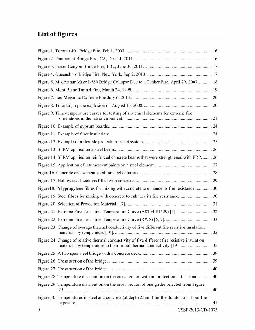
List of figures
Figure 1. Toronto 401 Bridge Fire, Feb 1, 2007. ........................................................................... 16
Figure 2. Paramount Bridge Fire, CA, Dec 14, 2011. ................................................................... 16
Figure 3. Fraser Canyon Bridge Fire, B.C., June 30, 2011. .......................................................... 17
Figure 4. Queensboro Bridge Fire, New York, Sep 2, 2013. ........................................................ 17
Figure 5. MacArthur Maze I-580 Bridge Collapse Due to a Tanker Fire, April 29, 2007. ........... 18
Figure 6. Mont Blanc Tunnel Fire, March 24, 1999. ..................................................................... 19
Figure 7. Lac-Mégantic Extreme Fire July 6, 2013. ...................................................................... 20
Figure 8. Toronto propane explosion on August 10, 2008. ........................................................... 20
Figure 9. Time-temperature curves for testing of structural elements for extreme fire simulations in the lab environment. ............................................................................ 21
Figure 10. Example of gypsum boards. ......................................................................................... 24
Figure 11. Example of fiber insulations. ....................................................................................... 24
Figure 12. Example of a flexible protection jacket system. .......................................................... 25
Figure 13. SFRM applied on a steel beam..................................................................................... 26
Figure 14. SFRM applied on reinforced concrete beams that were strengthened with FRP. ........ 26
Figure 15. Application of intumescent paints on a steel element. ................................................. 27
Figure16. Concrete encasement used for steel columns. ............................................................... 28
Figure 17. Hollow steel sections filled with concrete. .................................................................. 29
Figure18. Polypropylene fibres for mixing with concrete to enhance its fire resistance. .............. 30
Figure 19. Steel fibres for mixing with concrete to enhance its fire resistance. ............................ 30
Figure 20. Selection of Protection Material [17]. .......................................................................... 31
Figure 21. Extreme Fire Test Time-Temperature Curve (ASTM E1529) [3]. .............................. 32
Figure 22. Extreme Fire Test Time-Temperature Curve (RWS) [6, 7]. ........................................ 33
Figure 23. Change of average thermal conductivity of five different fire resistive insulation materials by temperature [19]. .................................................................................... 35
Figure 24. Change of relative thermal conductivity of five different fire resistive insulation materials by temperature to their initial thermal conductivity [19]. ............................ 35
Figure 25. A two span steel bridge with a concrete deck. ............................................................. 39
Figure 26. Cross section of the bridge. .......................................................................................... 39
Figure 27. Cross section of the bridge. .......................................................................................... 40
Figure 28. Temperature distribution on the cross section with no protection at t=1 hour. ............ 40
Figure 29. Temperature distribution on the cross section of one girder selected from Figure 29. ................................................................................................................................ 40
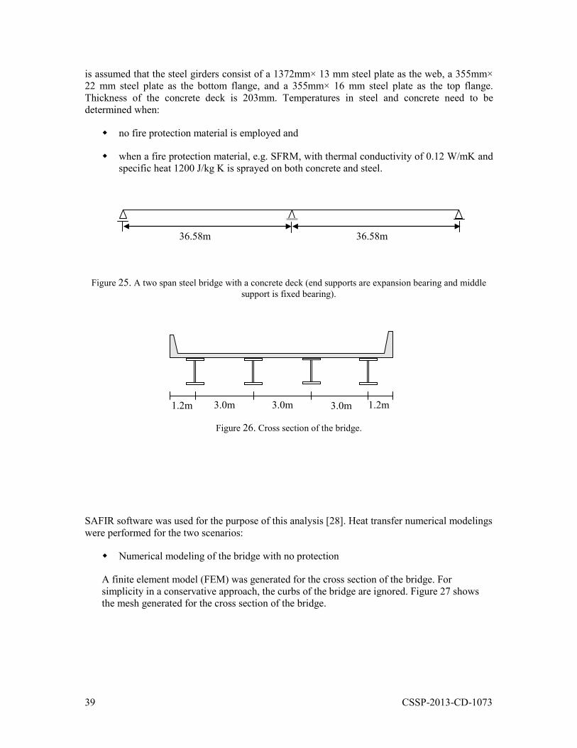
Figure 30. Temperatures in steel and concrete (at depth 25mm) for the duraton of 1 hour fire exposure. ..................................................................................................................... 41
10 CSSP-2013-CD-1073
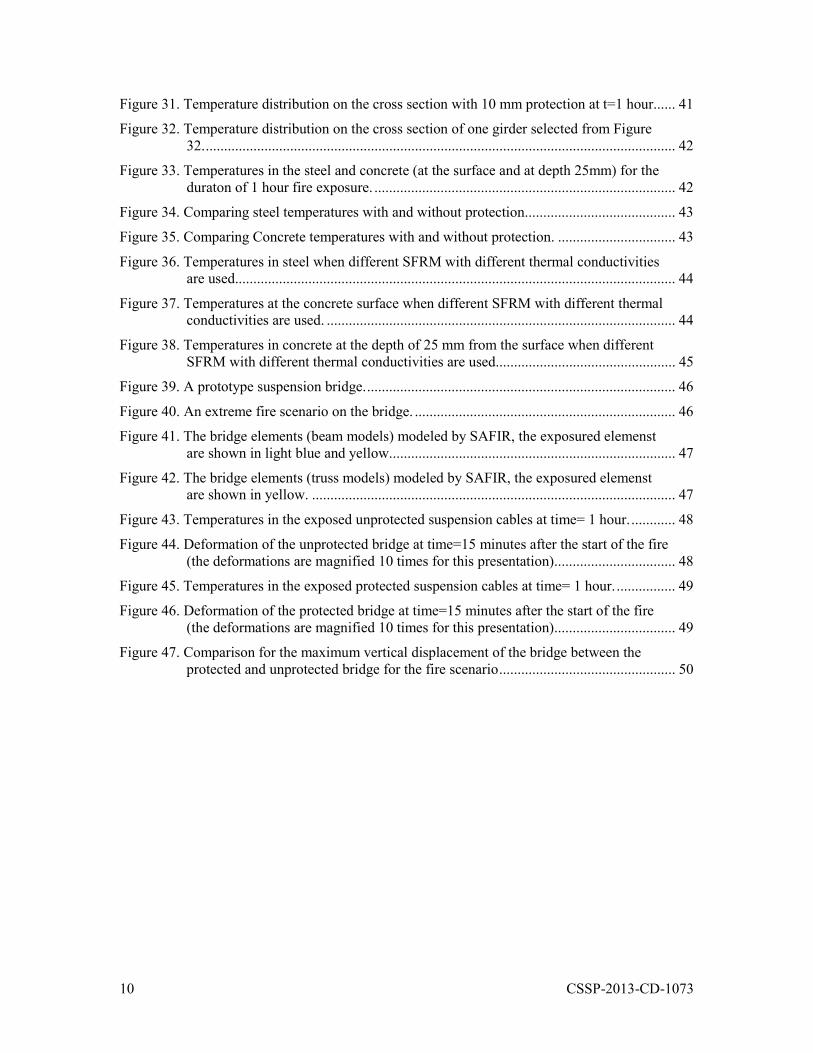
Figure 31. Temperature distribution on the cross section with 10 mm protection at t=1 hour. ..... 41
Figure 32. Temperature distribution on the cross section of one girder selected from Figure 32. ................................................................................................................................ 42
Figure 33. Temperatures in the steel and concrete (at the surface and at depth 25mm) for the duraton of 1 hour fire exposure. .................................................................................. 42
Figure 34. Comparing steel temperatures with and without protection. ........................................ 43
Figure 35. Comparing Concrete temperatures with and without protection. ................................ 43
Figure 36. Temperatures in steel when different SFRM with different thermal conductivities are used........................................................................................................................ 44
Figure 37. Temperatures at the concrete surface when different SFRM with different thermal conductivities are used. ............................................................................................... 44
Figure 38. Temperatures in concrete at the depth of 25 mm from the surface when different SFRM with different thermal conductivities are used. ................................................ 45
Figure 39. A prototype suspension bridge. .................................................................................... 46
Figure 40. An extreme fire scenario on the bridge. ....................................................................... 46
Figure 41. The bridge elements (beam models) modeled by SAFIR, the exposured elemenst are shown in light blue and yellow. ............................................................................. 47
Figure 42. The bridge elements (truss models) modeled by SAFIR, the exposured elemenst are shown in yellow. ................................................................................................... 47
Figure 43. Temperatures in the exposed unprotected suspension cables at time= 1 hour. ............ 48
Figure 44. Deformation of the unprotected bridge at time=15 minutes after the start of the fire (the deformations are magnified 10 times for this presentation) ................................. 48
Figure 45. Temperatures in the exposed protected suspension cables at time= 1 hour. ................ 49
Figure 46. Deformation of the protected bridge at time=15 minutes after the start of the fire (the deformations are magnified 10 times for this presentation) ................................. 49
Figure 47. Comparison for the maximum vertical displacement of the bridge between the protected and unprotected bridge for the fire scenario ................................................ 50

11 CSSP-2013-CD-1073
List of tables
Table 1. Main points on the Time-Temperature Curve (ASTM E1529) [3] ................................. 32
Table 2.The Time-Temperature Curve for tunnels (RWS) [6, 7] .................................................. 33

12 CSSP-2013-CD-1073
Acknowledgements
This work was supported by the Defence Research and Development Canada, Canadian Safety and Security Program (CSSP-2012-CD-1073). The authors would like to acknowledge Mr. Pierre Meunier for supporting this project. Authors are very grateful and would like to thank Dr. Darek Baingo from Defence Research and Development Canada, Mr. Ron Cowalchuk and Mr. Dwayne Goudie from Transport Canada, Mr. Antonio Aldykiewicz from Grace, and Mr. Richard Lapointe from Sika Canada for their input and support to this project. Authors would like to acknowledge Mr. Dave Edwards, from NRC, for his contribution through the implementation of this project.
13 CSSP-2013-CD-1073
1 Introduction
Currently, there is almost no design approach or extreme fire protection material available for protection of critical infrastructures such as bridges. The currently available fire protection materials and technologies are mainly evaluated and designed for normal building fires. There are few types of fire protection materials available that would be suitable for extreme fires. However, these materials are for specific applications such as fire protection of refinery structures or protection of tunnel linings. Selection of a suitable fire protection material is based on the types of application, e.g. bridges, tunnels and buildings, severity of the fire, e.g. normal fire or extreme fire, and exposure conditions, e.g. high humidity, salt spray, and freeze-thaw. For instance, for application in typical buildings, protection materials usually need to be tested in a normal fire [2, 3] with no exposure conditions. However, for refinery structures, they need to be evaluated for more severe fire [4, 5] with exposure conditions, such as industrial atmosphere. As for tunnels, they need to be exposed to even more extreme fire such as RWS [6, 7].
There are different fire protection methods including; active fire protection and passive fire protection. Active fire protections are systems that require a certain amount of motion/or action, e.g. slowing the fire progress, extinguishing the fire such as using sprinklers. On the other hand, passive fire protection systems don’t require such motion/action and are inherited in the structure, such as using spray applied materials or intumescent coating to protect structural elements. A brief summary on the active fire protection systems is provided in this report. However, more efforts have been extended toward identifying and reviewing passive fire protections. This is because passive fire protections are considered the last line of defence. There is always a risk that active fire protections don’t act in fire due to a malfunctioning. However, such a risk is very minimal for passive fire protection. Furthermore, active fire protections require much higher maintenance compared to passive fire protection. Therefore, they are not more suitable for critical infrastructures such as bridges which such a maintenance and risk of malfunctioning could not be afforded.
The scope of this study was primarily set on what are the common available passive fire protection materials and technologies and what would be the performance criteria to evaluate and select suitable protection solutions for the critical infrastructures against extreme fire. The outcome is expected to help critical infrastructure Community of Practice in the decision-making to enhance protection of critical infrastructure assets against extreme fire. This will improve the resiliency of the critical infrastructure by mitigating the incident impact and consequences.
14 CSSP-2013-CD-1073
2 Purpose
The main objectives of this project were:
- To identify existing materials and technologies for fire protection of structures, e.g. buildings, tunnels, and industry facilities.
- To recommend performance criteria that would be required for protection of critical infrastructures against extreme fire.
- To review the identified fire protection materials in the first step and recommend those that could be potential protection solutions for critical infrastructures against extreme fire based on the performance criteria.
15 CSSP-2013-CD-1073
3 Methodology
The main methodology employed in the implementation of this study was to carry out literature reviews and provide recommendations based on the available information. This chapter describes the applied methodology in three sections. The first section, Section 3.1, provides background information on what are critical infrastructures, what are extreme fires, and what types of fire protection materials and technologies are covered by this study. The second section, Section 3.2, provide information about different types of available fire protection materials and technologies. This information has been collected through a literature review. Section 3.3 provides information on criteria for selection of fire protection materials and technologies for critical infrastructures against extreme fire events. Finally, Section 3.5 provides recommendations on which of the identified fire protection materials would be suitable for application in critical infrastructures. More details of the available fire protection materials and technologies are provided in Appendix A.
3.1 Background
This section provides background information on the types of critical infrastructures, extreme fires and fire protection materials and technologies covered by this project..
3.1.1 Critical Infrastructures
Critical Infrastructure refers to facilities which their function is critical and vital to the safety and security of the nation society and economy. They may include energy facilities (electricity, gas, oil and other fuels), telecommunications, water and food supply, public health (hospitals), transportation, financial services and security services. In this report, the term critical infrastructures refers mainly to transportation infrastructures, e.g. bridges and tunnels, as well as critical buildings, e.g. government buildings and embassies. However, the information developed in this study could to some extent be applicable to other critical infrastructure facilities with comparable structural systems and fire and environmental exposure.
Bridges
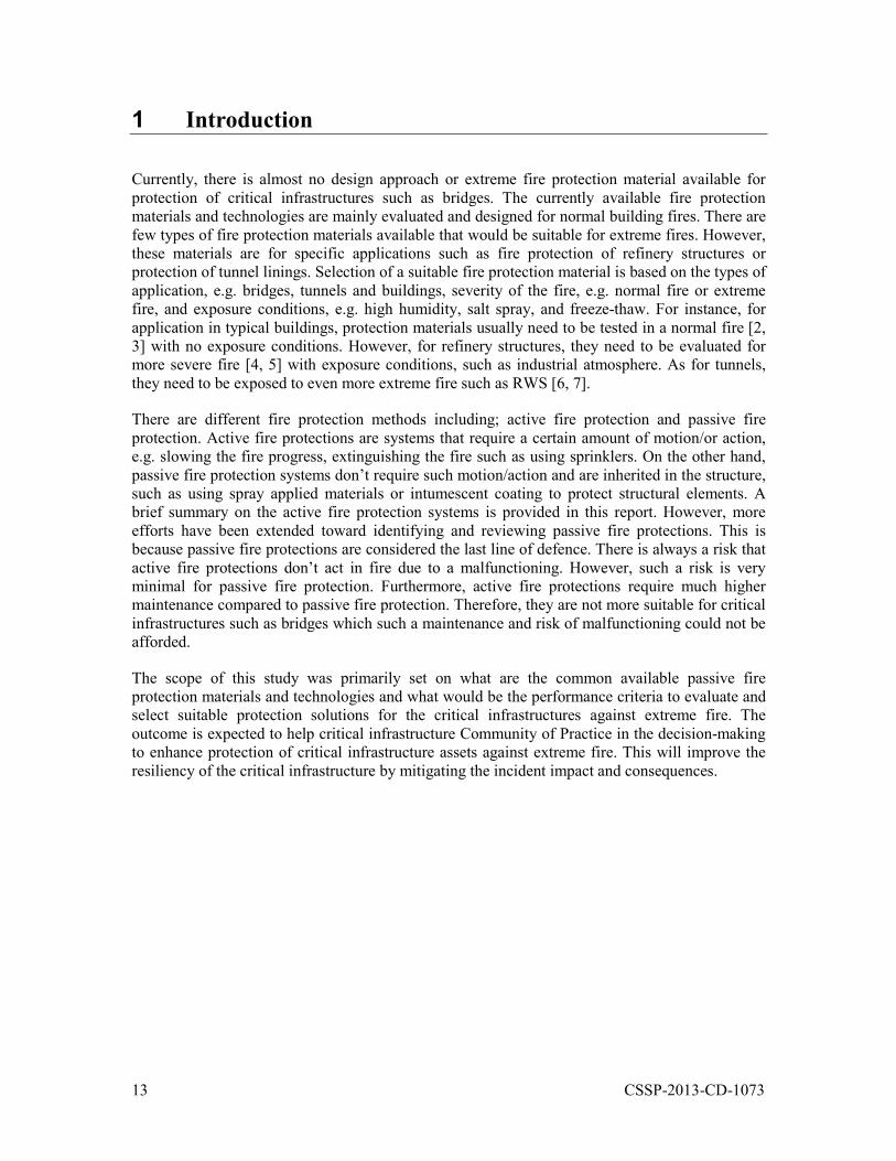
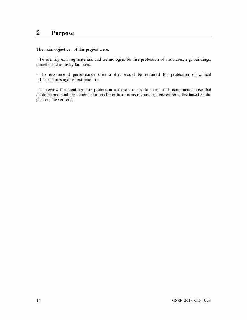
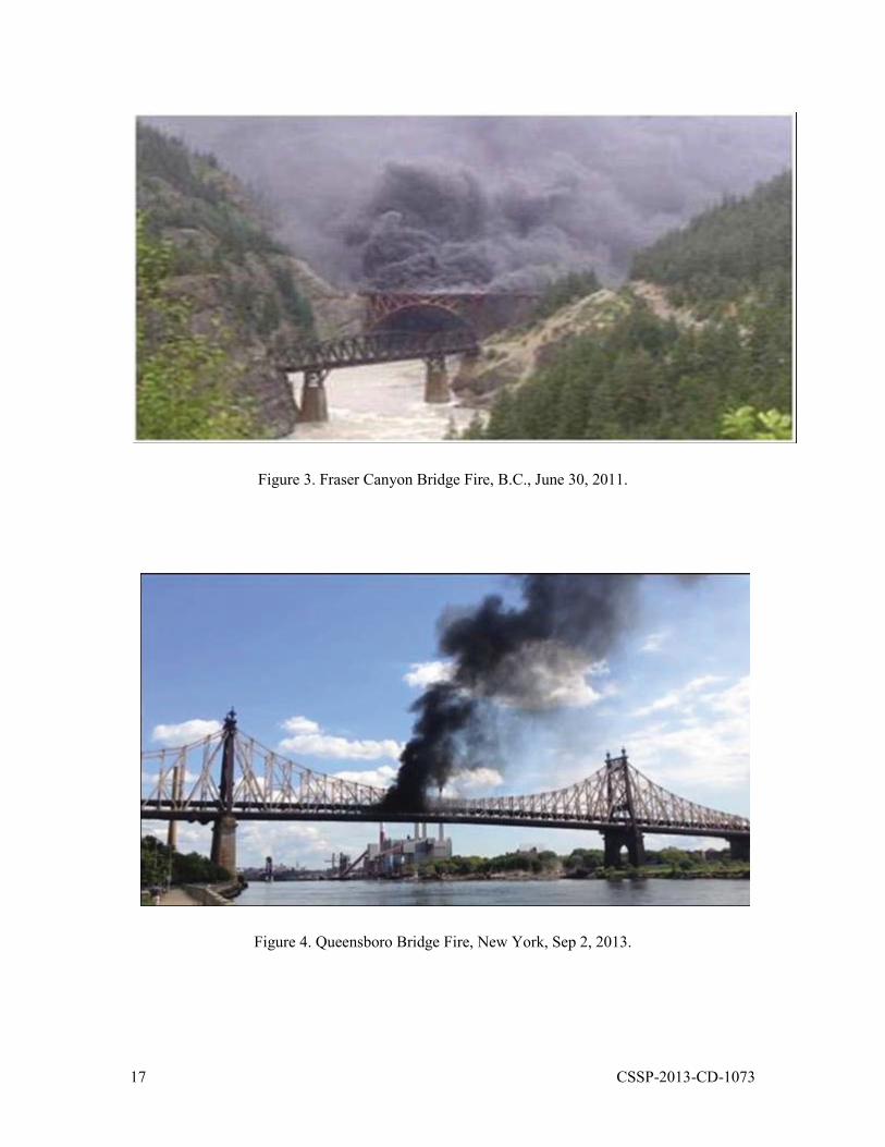
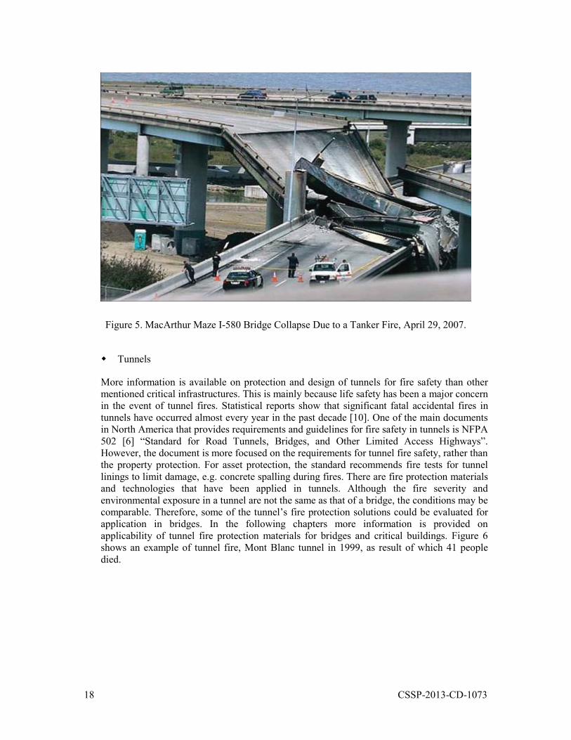
Hundreds of fatal crash events on bridges have been reported in the last decade across North America that resulted in fires. These incidents resulted in millions of dollars of loss due to the direct cost of the bridge damage and repair and indirect economic impact on the community as a result of the delay for the bridge recovery after the incidents [8, 9]. Figures 1 to 5 show examples of bridge fire incidents. Despite the large number of bridge fire incidents, the only current document in North America which reflects some design requirements for protection of bridges to fire is NFPA 502 “Standard for Road Tunnels, Bridges, and Other Limited Access Highways” [6]. NFPA 502 provides designers and regulators with guidelines for the construction, operation, maintenance, and fire protection of tunnels and bridges to mitigate hazards, maintain structural integrity, and protect lives. Although the scope of NFPA 502 is tunnels and bridges, most of the information has been developed for design and protection of tunnel structures. The needs for developing fire protection materials and technologies for bridges, particularly; critical bridges to reduce their damage and recovery time after such incidents were identified in a previous CSSP project [1]. Therefore, in this study more effort has been extended toward identifying fire protection materials and technologies for critical bridges.
16 CSSP-2013-CD-1073
Figure 1. Toronto 401 Bridge Fire, Feb 1, 2007.
Figure 2. Paramount Bridge Fire, CA, Dec 14, 2011.
17 CSSP-2013-CD-1073
Figure 3. Fraser Canyon Bridge Fire, B.C., June 30, 2011.
Figure 4. Queensboro Bridge Fire, New York, Sep 2, 2013.
18 CSSP-2013-CD-1073
Figure 5. MacArthur Maze I-580 Bridge Collapse Due to a Tanker Fire, April 29, 2007.
Tunnels
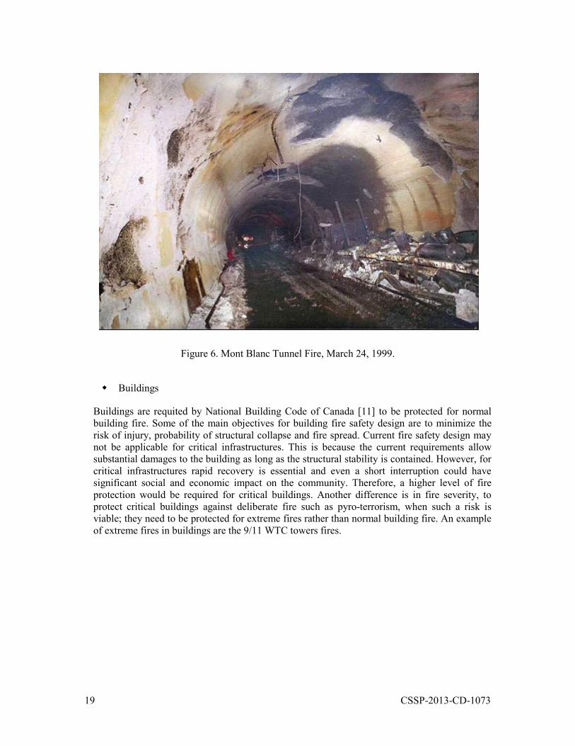
More information is available on protection and design of tunnels for fire safety than other mentioned critical infrastructures. This is mainly because life safety has been a major concern in the event of tunnel fires. Statistical reports show that significant fatal accidental fires in tunnels have occurred almost every year in the past decade [10]. One of the main documents in North America that provides requirements and guidelines for fire safety in tunnels is NFPA 502 [6] “Standard for Road Tunnels, Bridges, and Other Limited Access Highways”. However, the document is more focused on the requirements for tunnel fire safety, rather than the property protection. For asset protection, the standard recommends fire tests for tunnel linings to limit damage, e.g. concrete spalling during fires. There are fire protection materials and technologies that have been applied in tunnels. Although the fire severity and environmental exposure in a tunnel are not the same as that of a bridge, the conditions may be comparable. Therefore, some of the tunnel’s fire protection solutions could be evaluated for application in bridges. In the following chapters more information is provided on applicability of tunnel fire protection materials for bridges and critical buildings. Figure 6 shows an example of tunnel fire, Mont Blanc tunnel in 1999, as result of which 41 people died.
19 CSSP-2013-CD-1073
Figure 6. Mont Blanc Tunnel Fire, March 24, 1999.
Buildings
Buildings are requited by National Building Code of Canada [11] to be protected for normal building fire. Some of the main objectives for building fire safety design are to minimize the risk of injury, probability of structural collapse and fire spread. Current fire safety design may not be applicable for critical infrastructures. This is because the current requirements allow substantial damages to the building as long as the structural stability is contained. However, for critical infrastructures rapid recovery is essential and even a short interruption could have significant social and economic impact on the community. Therefore, a higher level of fire protection would be required for critical buildings. Another difference is in fire severity, to protect critical buildings against deliberate fire such as pyro-terrorism, when such a risk is viable; they need to be protected for extreme fires rather than normal building fire. An example of extreme fires in buildings are the 9/11 WTC towers fires.
20 CSSP-2013-CD-1073
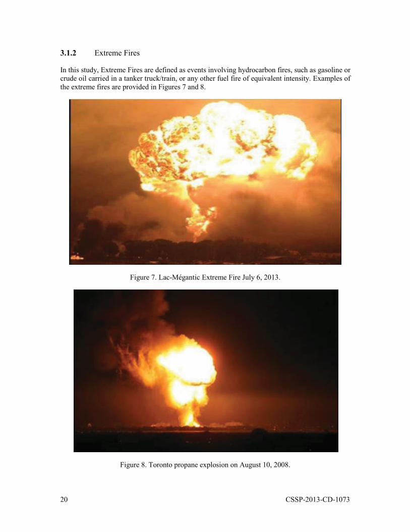
3.1.2 Extreme Fires
In this study, Extreme Fires are defined as events involving hydrocarbon fires, such as gasoline or crude oil carried in a tanker truck/train, or any other fuel fire of equivalent intensity. Examples of the extreme fires are provided in Figures 7 and 8.
Figure 7. Lac-Mégantic Extreme Fire July 6, 2013.
Figure 8. Toronto propane explosion on August 10, 2008.
21 CSSP-2013-CD-1073
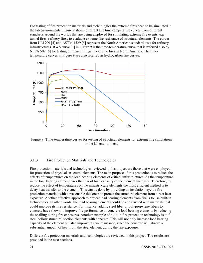
For testing of fire protection materials and technologies the extreme fires need to be simulated in the lab environments. Figure 9 shows different fire time-temperature curves from different standards around the worlds that are being employed for simulating extreme fire events, e.g. tunnel fires, refinery fires, to evaluate extreme fire resistance of structural elements. The curves from UL1709 [4] and ASTM 1529 [5] represent the North American standard tests for refinery infrastructures. RWS curve [7] in Figure 9 is the time-temperature curve that is referred also by NFPA 502 [6] for testing of tunnel linings in extreme fires in North America. The time-temperature curves in Figure 9 are also referred as hydrocarbon fire curves.
Figure 9. Time-temperature curves for testing of structural elements for extreme fire simulations in the lab environment.
3.1.3 Fire Protection Materials and Technologies
Fire protection materials and technologies reviewed in this project are those that were employed for protection of physical structural elements. The main purpose of this protection is to reduce the effects of temperatures on the load bearing elements of critical infrastructures. As the temperature in the load bearing element rises the loss of load capacity of the element increases. Therefore, to reduce the effect of temperatures on the infrastructure elements the most efficient method is to delay heat transfer to the element. This can be done by providing an insulation layer, a fire protection material, with a reasonable thickness to protect the structural element from direct heat exposure. Another effective approach to protect load bearing elements from fire is to use built-in technologies. In other words, the load bearing elements could be constructed with materials that could improve its fire resistance. For instance, adding steel fiber or polypropylene fibers to concrete have shown to improve fire performance of concrete load bearing elements by reducing the spalling during fire exposures. Another example of built-in fire protection technology is to fill steel hollow structural section elements with concrete. This will not only increase load bearing capacity of the element but also improve its fire resistance, since the concrete will absorb a substantial amount of heat from the steel element during the fire exposure.
Different fire protection materials and technologies are reviewed in this project. The results are provided in the next sections.
22 CSSP-2013-CD-1073
3.2 Review of Fire Protection Technologies
This section provides information on different types of available fire protection materials and technologies that were reviewed for of this study. Fire protection systems are mainly either Active Fire Protection or Passive Fire Protection. Active fire protections, e.g. sprinkler systems, hydrant, foam and detectors, require a certain amount of motion and response in order to work. However, passive fire protections are integrated within the infrastructures. Their main role is to prevent fire spread and reduce the risk of structural collapse. This report includes brief information about active fire protection systems and focus mainly on the review results for the passive fire protection systems, as it is the main objective of this study.
3.2.1 Active Fire Protection
An active fire protection is a system that requires a certain action to take place by a person or an automatic system to reduce the impact or effect of the fire on the infrastructure. Examples of active fire protection systems for typical structures include; fire detection, fire suppression, and sprinkler systems. Fire detections are systems installed in the buildings to detect smoke, flame or heat. They neither extinguish the fire nor provide direct fire protection. As the smoke, flame or heat is detected, an alarm will sound and inform the occupants to evacuate the buildings or dispatch fire services. For critical infrastructures, these systems have been used in critical tunnels. For bridges exposed to weather, application of fire detections may not be easily feasible. Fire suppressions are systems that act as fire extinguishers. This could be achieved either manually (e.g. by firefighters) or automatically (e.g. by sprinkler systems). Sprinkler systems are widely used in different types of constructions including commercial and residential buildings. Due to the costs and challenges for maintenance and the risk that the sprinklers may not function during a fire, sprinkler systems would be suitable only for the critical infrastructures that these challenges could be resolved and the risk could be managed. Even though, active fire protection systems are used widely in buildings and other structures, the structures need to be designed for and include passive fire protection that will perform as the last line of defence.
3.2.2 Passive Fire Protection
In buildings, passive fire protections are used to provide structural fire protection and fire safety. These will be achieved by improving fire resistance of the structural elements and designing the buildings with small fire compartments. To improve fire resistance of the structural elements, there are two main methods reviewed here; exterior fire protections and built-in fire protections. Exterior fire protections are insulation materials that could be installed after construction of the structural elements as a layer of fire protection on the top. This is a suitable approach for both new and existing constructions. On the other hand, built-in fire protections are technologies or methods by which one can design and build the entire structural elements with materials that could resist fire. The built-in approach is mainly applicable for new constructions, since the fire protection materials are integrated within the structural elements. To enhance fire safety, small fire compartments need to be designed using fire resistant columns, beams, wall and floor elements, so they can confine the fire and prevent spread of smoke, flame and heat to other locations in the buildings. For protection of critical infrastructures to extreme fires, passive fire protection method, play a major role. In tunnels, for instance, refuge areas are designed for certain locations along the tunnels with fire resistant materials to ensure safety of the users during a potential fire. Furthermore, for protection of tunnel linings, fire protection materials could be
23 CSSP-2013-CD-1073
sprayed on or in case of new tunnels the lining could be built with materials that not only resist the required applied load but also the fire exposure.
There are many types of fire protection materials currently available. This section reviews only different types of such passive fire protection methods that could be potential solutions for protection of critical infrastructures, including tunnels, bridges, and critical buildings, to extreme fire.
Removable Fire Protection
Removable fire protection are materials or systems that are installed on the surface of the structural elements to protect them from fire. They are not pasted or attached to the elements and can be easily removed or replaced when an inspection of the structural elements or maintenance is required. Removable fire protection can be made of rigid panels and or flexible blankets, examples include:
Gypsum board: A gypsum board, referred to also as plasterboard, drywall, wall board or gyprock, is made of gypsum plaster pressed between two sheets of paper to form a rigid panel. Gypsum boards are the most common interior finishing materials for buildings. Figure 10 shows examples of regular gypsum boards. Regular type gypsum boards provide good natural fire resistance. Adding glass fibre to regular gypsum board increases its natural fire resistance. Performance of gypsum boards are not typically tested exposed to extreme fires. However, it is likely that plasterboard dehydrates in an extreme fire. This would result in a rapid surface shrinkage due to decomposition of hydrates in the material and a shorter fire resistance [12]. Gypsum boards are suitable for interior applications, e.g. buildings. For exterior application, e.g. bridges or tunnels, the available typical types of gypsum boards, due to weather exposure, may not be directly applicable.
Fiber insulation: Most common flexible fiber insulation for fire resistance application is ceramic fiber. Some of the Fiberfrax refractory ceramic fibre could withstand temperatures of more than 1450 degree C, which makes them suitable for use in furnaces and similar environments. However, due to the cost and impact of weather exposure on the insulation, as well as possible health risk by inhalation (mainly concern for interior application), application of the fibre insulation would be limited to special interior application. It is not suitable for bridges or tunnels. Figure 11 shows an example of fiber insulation.

24 CSSP-2013-CD-1073
Figure 10. Example of gypsum boards.
Figure 11. Example of fiber insulations.
25 CSSP-2013-CD-1073
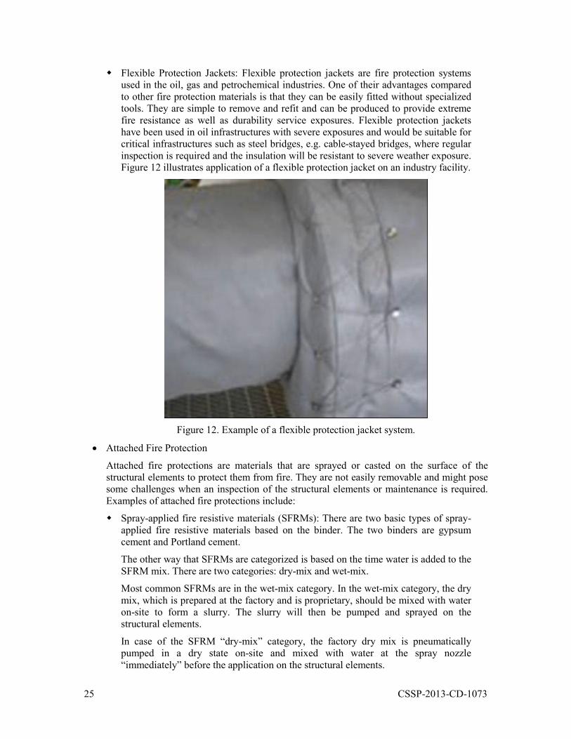
Flexible Protection Jackets: Flexible protection jackets are fire protection systems used in the oil, gas and petrochemical industries. One of their advantages compared to other fire protection materials is that they can be easily fitted without specialized tools. They are simple to remove and refit and can be produced to provide extreme fire resistance as well as durability service exposures. Flexible protection jackets have been used in oil infrastructures with severe exposures and would be suitable for critical infrastructures such as steel bridges, e.g. cable-stayed bridges, where regular inspection is required and the insulation will be resistant to severe weather exposure. Figure 12 illustrates application of a flexible protection jacket on an industry facility.
Figure 12. Example of a flexible protection jacket system.
Attached Fire Protection
Attached fire protections are materials that are sprayed or casted on the surface of the structural elements to protect them from fire. They are not easily removable and might pose some challenges when an inspection of the structural elements or maintenance is required. Examples of attached fire protections include:
Spray-applied fire resistive materials (SFRMs): There are two basic types of spray-applied fire resistive materials based on the binder. The two binders are gypsum cement and Portland cement.
The other way that SFRMs are categorized is based on the time water is added to the SFRM mix. There are two categories: dry-mix and wet-mix.
Most common SFRMs are in the wet-mix category. In the wet-mix category, the dry mix, which is prepared at the factory and is proprietary, should be mixed with water on-site to form a slurry. The slurry will then be pumped and sprayed on the structural elements.
In case of the SFRM “dry-mix” category, the factory dry mix is pneumatically pumped in a dry state on-site and mixed with water at the spray nozzle “immediately” before the application on the structural elements.
26 CSSP-2013-CD-1073
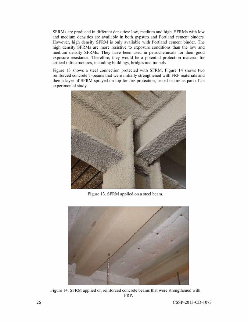
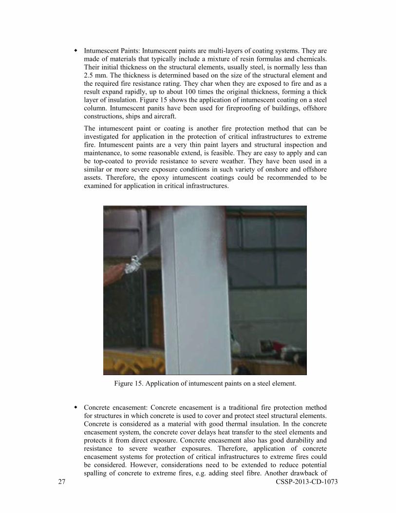
SFRMs are produced in different densities: low, medium and high. SFRMs with low and medium densities are available in both gypsum and Portland cement binders. However, high density SFRM is only available with Portland cement binder. The high density SFRMs are more resistive to exposure conditions than the low and medium density SFRMs. They have been used in petrochemicals for their good exposure resistance. Therefore, they would be a potential protection material for critical infrastructures, including buildings, bridges and tunnels.
Figure 13 shows a steel connection protected with SFRM. Figure 14 shows two reinforced concrete T-beams that were initially strengthened with FRP materials and then a layer of SFRM sprayed on top for fire protection, tested in fire as part of an experimental study.
Figure 13. SFRM applied on a steel beam.
Figure 14. SFRM applied on reinforced concrete beams that were strengthened with FRP.
27 CSSP-2013-CD-1073
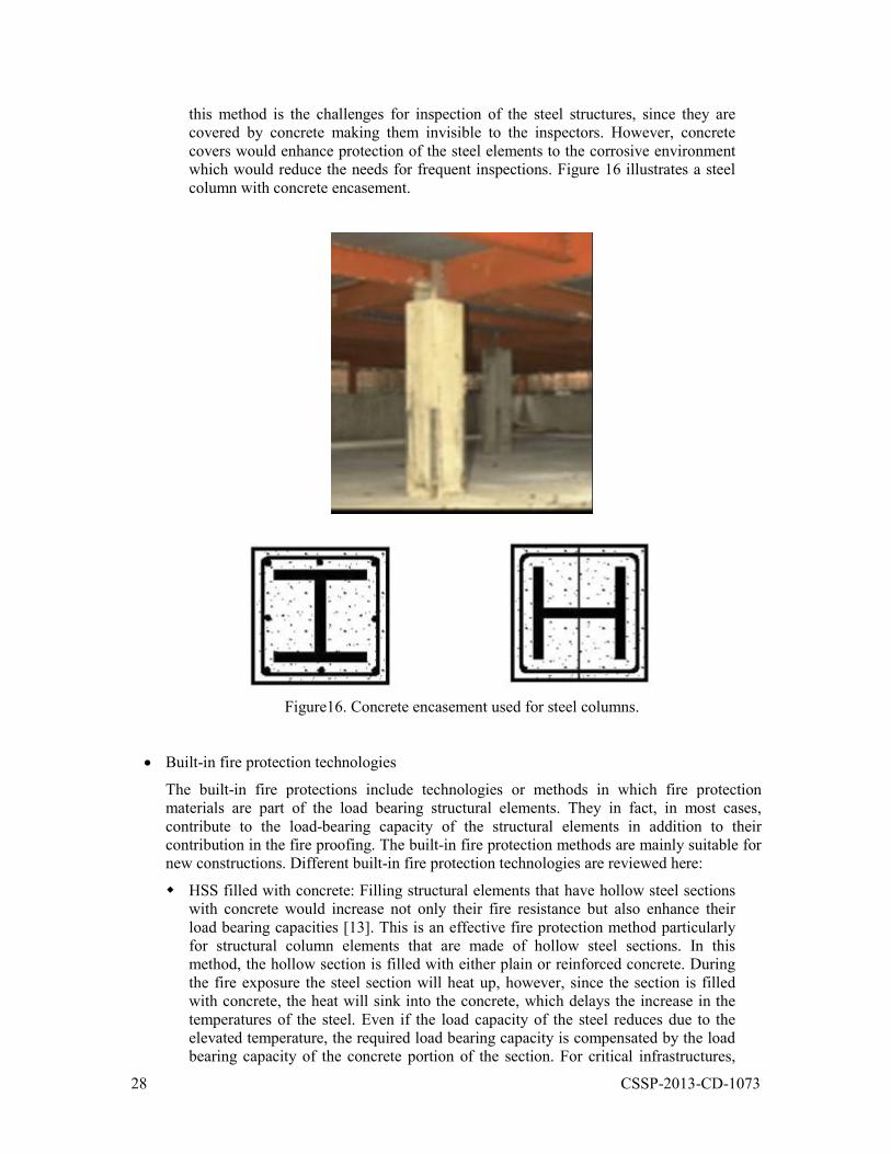
Intumescent Paints: Intumescent paints are multi-layers of coating systems. They are made of materials that typically include a mixture of resin formulas and chemicals. Their initial thickness on the structural elements, usually steel, is normally less than 2.5 mm. The thickness is determined based on the size of the structural element and the required fire resistance rating. They char when they are exposed to fire and as a result expand rapidly, up to about 100 times the original thickness, forming a thick layer of insulation. Figure 15 shows the application of intumescent coating on a steel column. Intumescent panits have been used for fireproofing of buildings, offshore constructions, ships and aircraft.
The intumescent paint or coating is another fire protection method that can be investigated for application in the protection of critical infrastructures to extreme fire. Intumescent paints are a very thin paint layers and structural inspection and maintenance, to some reasonable extend, is feasible. They are easy to apply and can be top-coated to provide resistance to severe weather. They have been used in a similar or more severe exposure conditions in such variety of onshore and offshore assets. Therefore, the epoxy intumescent coatings could be recommended to be examined for application in critical infrastructures.
Figure 15. Application of intumescent paints on a steel element.
Concrete encasement: Concrete encasement is a traditional fire protection method for structures in which concrete is used to cover and protect steel structural elements. Concrete is considered as a material with good thermal insulation. In the concrete encasement system, the concrete cover delays heat transfer to the steel elements and protects it from direct exposure. Concrete encasement also has good durability and resistance to severe weather exposures. Therefore, application of concrete encasement systems for protection of critical infrastructures to extreme fires could be considered. However, considerations need to be extended to reduce potential spalling of concrete to extreme fires, e.g. adding steel fibre. Another drawback of
28 CSSP-2013-CD-1073
this method is the challenges for inspection of the steel structures, since they are covered by concrete making them invisible to the inspectors. However, concrete covers would enhance protection of the steel elements to the corrosive environment which would reduce the needs for frequent inspections. Figure 16 illustrates a steel column with concrete encasement.
Figure16. Concrete encasement used for steel columns.
Built-in fire protection technologies
The built-in fire protections include technologies or methods in which fire protection materials are part of the load bearing structural elements. They in fact, in most cases, contribute to the load-bearing capacity of the structural elements in addition to their contribution in the fire proofing. The built-in fire protection methods are mainly suitable for new constructions. Different built-in fire protection technologies are reviewed here:
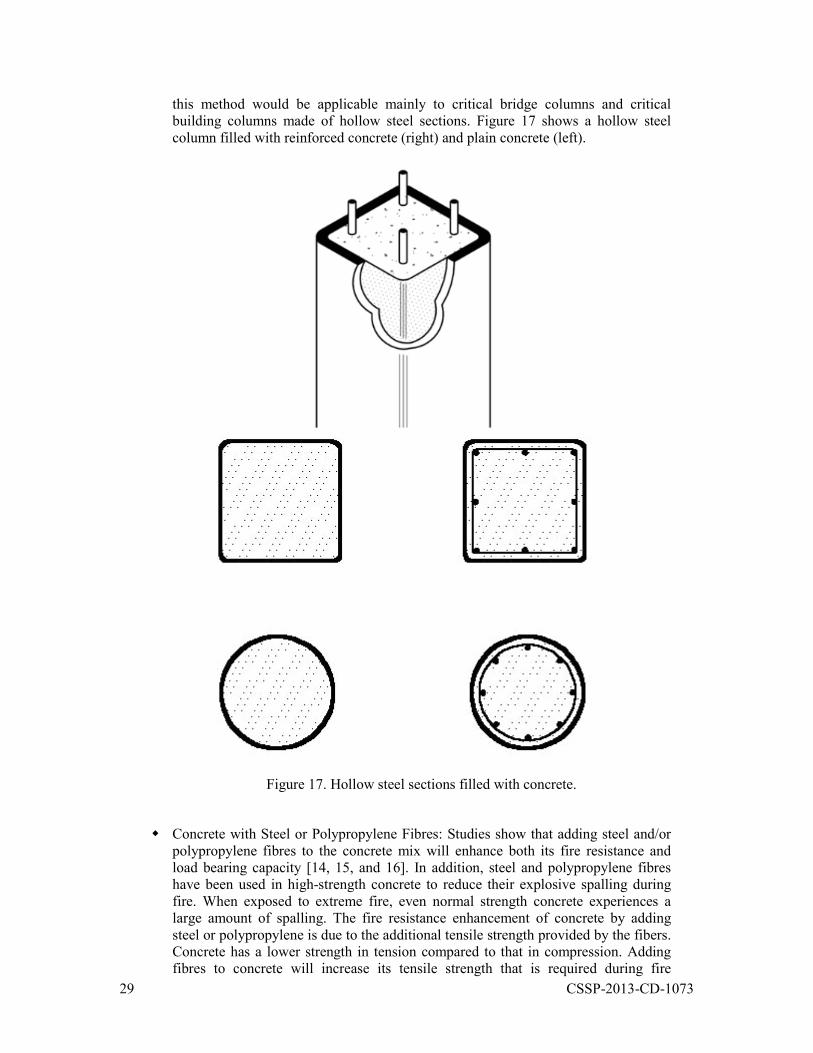
HSS filled with concrete: Filling structural elements that have hollow steel sections with concrete would increase not only their fire resistance but also enhance their load bearing capacities [13]. This is an effective fire protection method particularly for structural column elements that are made of hollow steel sections. In this method, the hollow section is filled with either plain or reinforced concrete. During the fire exposure the steel section will heat up, however, since the section is filled with concrete, the heat will sink into the concrete, which delays the increase in the temperatures of the steel. Even if the load capacity of the steel reduces due to the elevated temperature, the required load bearing capacity is compensated by the load bearing capacity of the concrete portion of the section. For critical infrastructures,
29 CSSP-2013-CD-1073
this method would be applicable mainly to critical bridge columns and critical building columns made of hollow steel sections. Figure 17 shows a hollow steel column filled with reinforced concrete (right) and plain concrete (left).
Figure 17. Hollow steel sections filled with concrete.
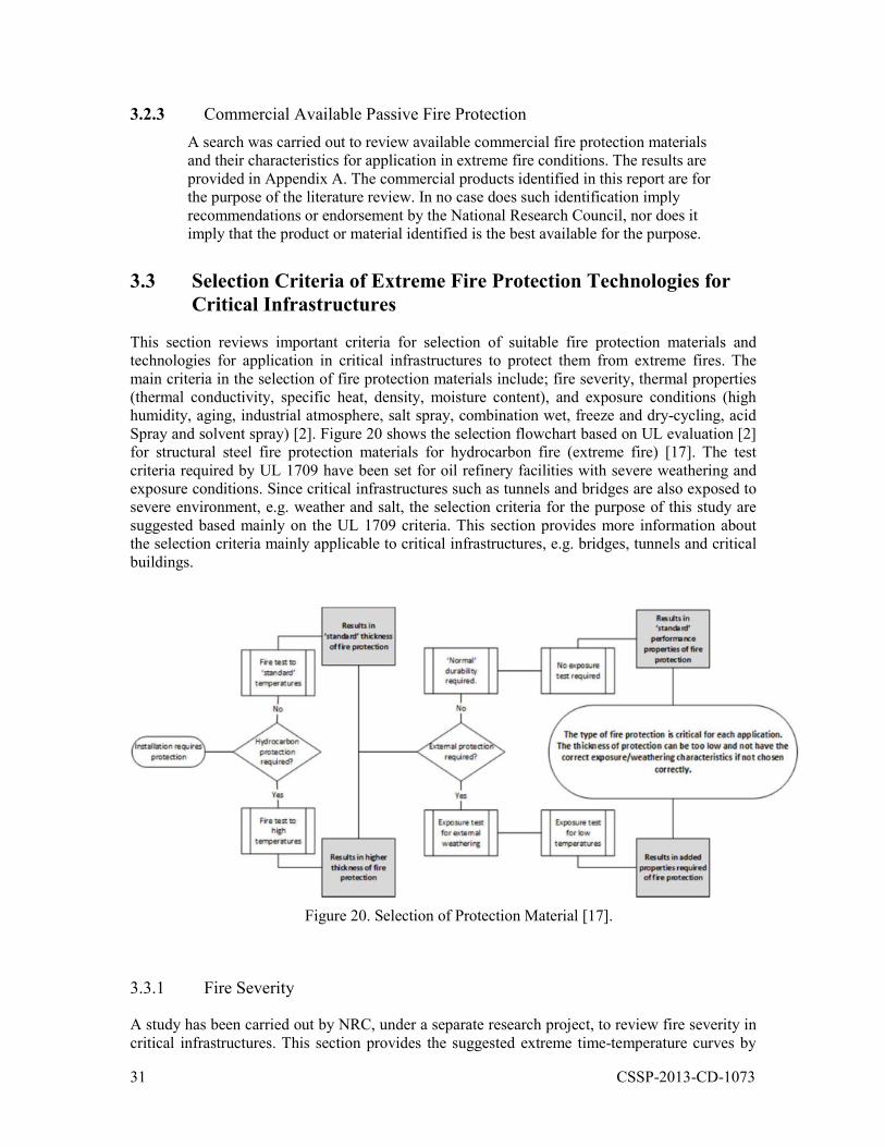
Concrete with Steel or Polypropylene Fibres: Studies show that adding steel and/or polypropylene fibres to the concrete mix will enhance both its fire resistance and load bearing capacity [14, 15, and 16]. In addition, steel and polypropylene fibres have been used in high-strength concrete to reduce their explosive spalling during fire. When exposed to extreme fire, even normal strength concrete experiences a large amount of spalling. The fire resistance enhancement of concrete by adding steel or polypropylene is due to the additional tensile strength provided by the fibers. Concrete has a lower strength in tension compared to that in compression. Adding fibres to concrete will increase its tensile strength that is required during fire
30 CSSP-2013-CD-1073
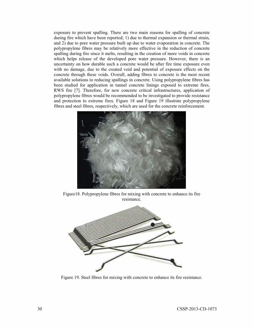
exposure to prevent spalling. There are two main reasons for spalling of concrete during fire which have been reported; 1) due to thermal expansion or thermal strain, and 2) due to pore water pressure built up due to water evaporation in concrete. The polypropylene fibres may be relatively more effective in the reduction of concrete spalling during fire since it melts, resulting in the creation of more voids in concrete which helps release of the developed pore water pressure. However, there is an uncertainty on how durable such a concrete would be after fire time exposure even with no damage, due to the created void and potential of exposure effects on the concrete through these voids. Overall, adding fibres to concrete is the most recent available solutions to reducing spallings in concrete. Using polypropylene fibres has been studied for application in tunnel concrete linings exposed to extreme fires, RWS fire [7]. Therefore, for new concrete critical infrastructures, application of polypropylene fibres would be recommended to be investigated to provide resistance and protection to extreme fires. Figure 18 and Figure 19 illustrate polypropylene fibres and steel fibres, respectively, which are used for the concrete reinforcement.
Figure18. Polypropylene fibres for mixing with concrete to enhance its fire
resistance.
Figure 19. Steel fibres for mixing with concrete to enhance its fire resistance.
31 CSSP-2013-CD-1073
3.2.3 Commercial Available Passive Fire Protection A search was carried out to review available commercial fire protection materials and their characteristics for application in extreme fire conditions. The results are provided in Appendix A. The commercial products identified in this report are for the purpose of the literature review. In no case does such identification imply recommendations or endorsement by the National Research Council, nor does it imply that the product or material identified is the best available for the purpose.
3.3 Selection Criteria of Extreme Fire Protection Technologies for Critical Infrastructures
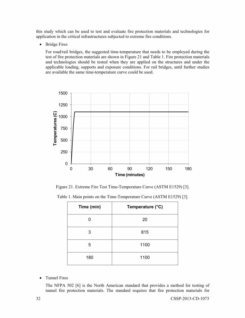
This section reviews important criteria for selection of suitable fire protection materials and technologies for application in critical infrastructures to protect them from extreme fires. The main criteria in the selection of fire protection materials include; fire severity, thermal properties (thermal conductivity, specific heat, density, moisture content), and exposure conditions (high humidity, aging, industrial atmosphere, salt spray, combination wet, freeze and dry-cycling, acid Spray and solvent spray) [2]. Figure 20 shows the selection flowchart based on UL evaluation [2] for structural steel fire protection materials for hydrocarbon fire (extreme fire) [17]. The test criteria required by UL 1709 have been set for oil refinery facilities with severe weathering and exposure conditions. Since critical infrastructures such as tunnels and bridges are also exposed to severe environment, e.g. weather and salt, the selection criteria for the purpose of this study are suggested based mainly on the UL 1709 criteria. This section provides more information about the selection criteria mainly applicable to critical infrastructures, e.g. bridges, tunnels and critical buildings.
Figure 20. Selection of Protection Material [17].
3.3.1 Fire Severity
A study has been carried out by NRC, under a separate research project, to review fire severity in critical infrastructures. This section provides the suggested extreme time-temperature curves by
32 CSSP-2013-CD-1073
this study which can be used to test and evaluate fire protection materials and technologies for application in the critical infrastructures subjected to extreme fire conditions.
Bridge Fires
For road/rail bridges, the suggested time-temperature that needs to be employed during the test of fire protection materials are shown in Figure 21 and Table 1. Fire protection materials and technologies should be tested when they are applied on the structures and under the applicable loading, supports and exposure conditions. For rail bridges, until further studies are available the same time-temperature curve could be used.
0
250
500
750
1000
1250
1500
0 30 60 90 120 150 180
Tem
pera
ture
s (C
)
Time (minutes)
Figure 21. Extreme Fire Test Time-Temperature Curve (ASTM E1529) [3].
Table 1. Main points on the Time-Temperature Curve (ASTM E1529) [3].
Time (min) Temperature (°C)
0 20
3 815
5 1100
180 1100
Tunnel Fires
The NFPA 502 [6] is the North American standard that provides a method for testing of tunnel fire protection materials. The standard requires that fire protection materials for
33 CSSP-2013-CD-1073
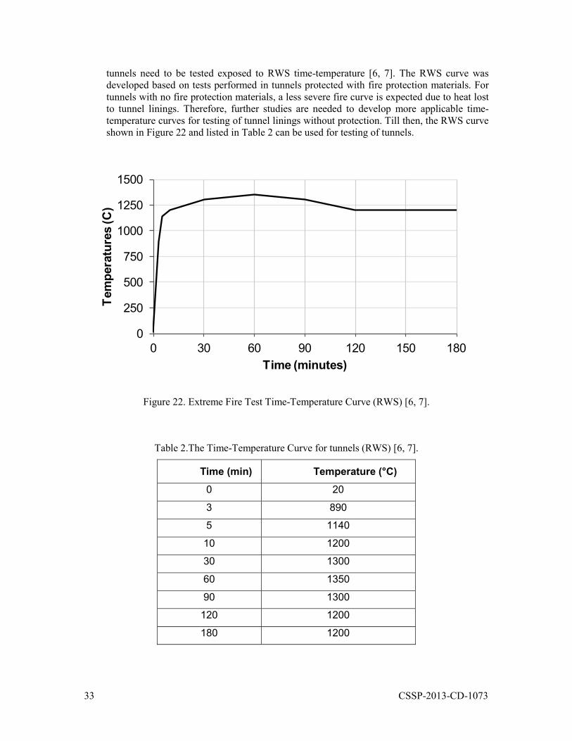
tunnels need to be tested exposed to RWS time-temperature [6, 7]. The RWS curve was developed based on tests performed in tunnels protected with fire protection materials. For tunnels with no fire protection materials, a less severe fire curve is expected due to heat lost to tunnel linings. Therefore, further studies are needed to develop more applicable time-temperature curves for testing of tunnel linings without protection. Till then, the RWS curve shown in Figure 22 and listed in Table 2 can be used for testing of tunnels.
0
250
500
750
1000
1250
1500
0 30 60 90 120 150 180
Tem
pera
ture
s (C
)
Time (minutes)
Figure 22. Extreme Fire Test Time-Temperature Curve (RWS) [6, 7].
Table 2.The Time-Temperature Curve for tunnels (RWS) [6, 7].
Time (min) Temperature (°C) 0 20
3 890
5 1140
10 1200
30 1300
60 1350
90 1300
120 1200
180 1200
34 CSSP-2013-CD-1073
Critical Building Fires
Critical buildings include government buildings and embassies. This category includes deliberate extreme fires such as pyro-terrorism; e.g. WTC towers and Pentagon extreme fires in 9/11. To evaluate and develop fire protection materials for critical buildings to such threats, ASTM E1529 time-temperature curves in Figure 21 have been suggested.
3.3.2 Thermal Properties
Thermal properties of the fire protection materials play a major role in the amount of heat transferred to the structural elements. The main thermal properties include thermal conductivity, specific heat, density, and moisture content. This section provides information on how these properties affect the fire performance of the structures protected with the protection materials.
Thermal Conductivity
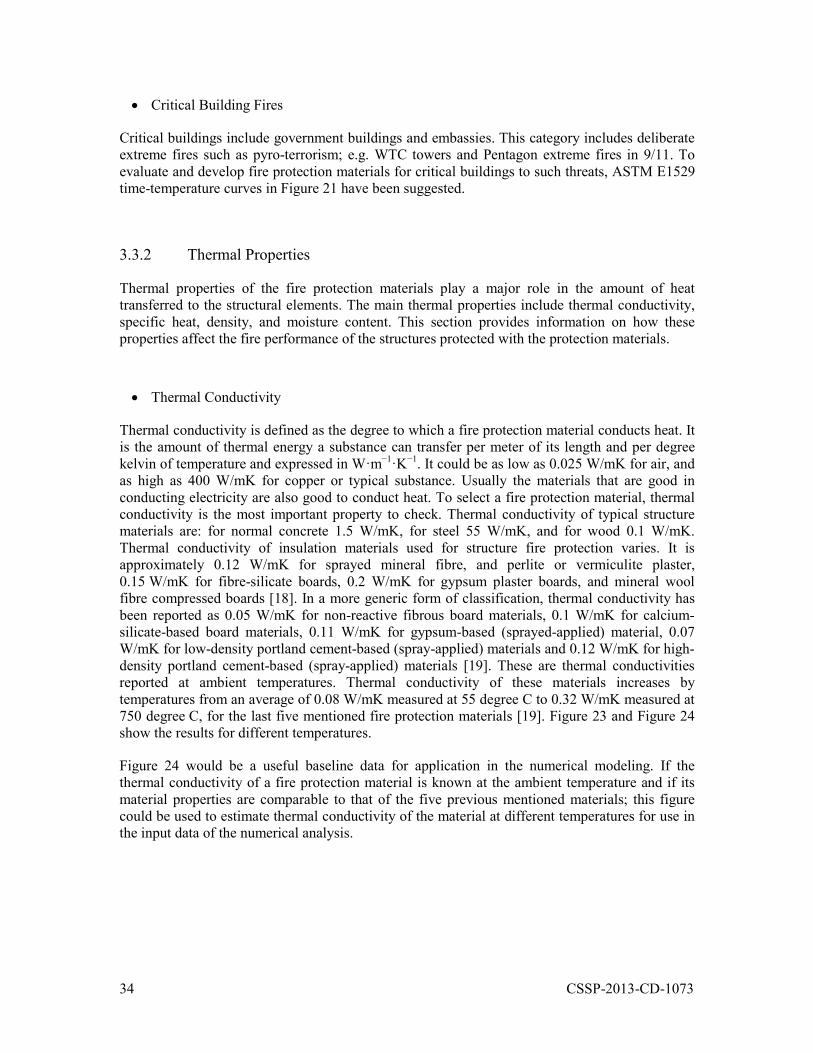
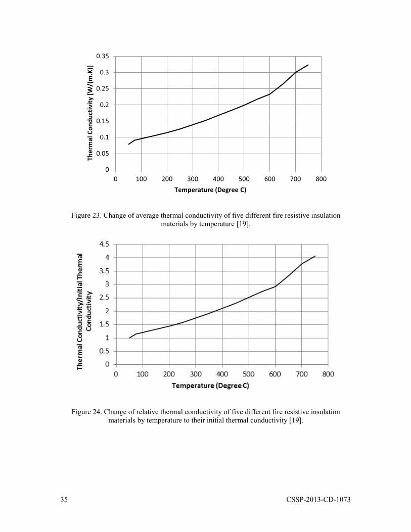
Thermal conductivity is defined as the degree to which a fire protection material conducts heat. It is the amount of thermal energy a substance can transfer per meter of its length and per degree kelvin of temperature and expressed in W·m ·K . It could be as low as 0.025 W/mK for air, and as high as 400 W/mK for copper or typical substance. Usually the materials that are good in conducting electricity are also good to conduct heat. To select a fire protection material, thermal conductivity is the most important property to check. Thermal conductivity of typical structure materials are: for normal concrete 1.5 W/mK, for steel 55 W/mK, and for wood 0.1 W/mK. Thermal conductivity of insulation materials used for structure fire protection varies. It is approximately 0.12 W/mK for sprayed mineral fibre, and perlite or vermiculite plaster, 0.15 W/mK for fibre-silicate boards, 0.2 W/mK for gypsum plaster boards, and mineral wool fibre compressed boards [18]. In a more generic form of classification, thermal conductivity has been reported as 0.05 W/mK for non-reactive fibrous board materials, 0.1 W/mK for calcium-silicate-based board materials, 0.11 W/mK for gypsum-based (sprayed-applied) material, 0.07 W/mK for low-density portland cement-based (spray-applied) materials and 0.12 W/mK for high-density portland cement-based (spray-applied) materials [19]. These are thermal conductivities reported at ambient temperatures. Thermal conductivity of these materials increases by temperatures from an average of 0.08 W/mK measured at 55 degree C to 0.32 W/mK measured at 750 degree C, for the last five mentioned fire protection materials [19]. Figure 23 and Figure 24 show the results for different temperatures.
Figure 24 would be a useful baseline data for application in the numerical modeling. If the thermal conductivity of a fire protection material is known at the ambient temperature and if its material properties are comparable to that of the five previous mentioned materials; this figure could be used to estimate thermal conductivity of the material at different temperatures for use in the input data of the numerical analysis.
35 CSSP-2013-CD-1073
0
0.05
0.1
0.15
0.2
0.25
0.3
0.35
0 100 200 300 400 500 600 700 800
Ther
mal
Con
duct
ivity
[W/(
m.K
)]
Temperature (Degree C)
Figure 23. Change of average thermal conductivity of five different fire resistive insulation materials by temperature [19].
Figure 24. Change of relative thermal conductivity of five different fire resistive insulation materials by temperature to their initial thermal conductivity [19].
36 CSSP-2013-CD-1073
Other Thermal Properties
In the design, to calculate heat transfer, thermal conductivity of the fire protection material is the main employed thermal property. However, understanding other thermal properties that could affect the thermal conductivity and heat transfer in fire protection material will assist selection of the suitable insulation method for structures. Other important properties include specific heat, density, and moisture content.
Specific heat is the amount of heat required per unit mass to raise the temperature by one degree Kelvin (or C), which is expressed usually in J/(kg.K). This property can be determined using the tests for obtaining the thermal conductivity. Specific heat is 600 J/(kg.K) for steel, 1000 J/(kg.K) for normal concrete, 840 J/(kg.K) for lightweight concrete and about 1.8 J/(kg.K) for wood. For typical fire protection materials it ranges from 1000 J/(kgK) to 1700 J/kg/K [18].
Density of the fire protection material would also affect the amount of heat transfer by the fire protection materials. For instance low-density concrete has a lower thermal conductivity than normal-density concrete and therefore it is a better insulation material.
Moisture content is another important property that could affect the amount of heat transfer by the fire protection material. The higher the moisture content is, the lower the heat transfer is. Moisture content would change based on the environmental conditions, e.g. humidity. Therefore, the fire protection material needs to reach the equilibrium moisture content for the required condition before implementation of fire performance assessment.
3.3.3 Exposure Conditions
UL1709-“Rapid Rise Fire Tests of Protection Materials for Structural Steel” provides a test procedure for the evaluation of fire protection materials exposed to hydrocarbon fires. This standard has been applied by the oil refinery industry to test mainly the application of spray-applied fire resistive materials of the steel structure of their facilities. Considering the severe exposure conditions that these facilities are designed for, information in this standard has been reviewed to provide recommendations for the selection criteria of fire protection materials for application in critical infrastructures. UL 1709 describes how the fire test needs to be performed with or without environmental exposure. If the test requires environmental exposure, the test samples need to be exposed to the required conditions based on UL 2431 - Durability of Spray-Applied Fire Resistive Materials [20]. UL 2431 standard describes a method to measure the ability of fire resistive materials to retain their fire resistive properties after being subjected to various conditioning environments. Conditioning environments described by the standard includes: air erosion, a combination of wet, freeze and dry cycling, humidity, impact resistance, industrial atmosphere, salt spray, temperature stability, ultraviolet light, and vibration [20].
Another standard that describes conditioning environments for fire protection materials is NFPA 502- Standard for Road Tunnels, Bridges, and Other Limited Access Highways [6]. NFPA 502 addresses the environmental conditionings in terms of performance criteria and requires that fire protection materials should:
Be resistant to freezing and thawing
Withstand dynamic suction and pressure loads
Withstand both hot and cold thermal shock from fire exposure and hose streams
37 CSSP-2013-CD-1073
Meet all applicable health and safety standards
Not itself becoming a hazard during a fire
Be resistant to water ingress
However, the document doesn’t clearly explain how these tests need to be performed. There are other standards that provide methods for conditioning environments, including:
ISO 4628-8, “Paints and varnishes -- Evaluation of degradation of coatings -- Designation of quantity and size of defects, and of intensity of uniform changes in appearance -- Part 8: Assessment” [21]. This standard can be used to evaluate delamination and corrosion around a scribe or other artificial defect on a coated panel or other coated test specimen, caused by a corrosive environment.
ASTM B117 – 11, Standard Practice for Operating Salt Spray (Fog) Apparatus [22]. This standard describes procedures and conditions required to create and maintain the salt spray (fog) test environment.
ISO 7253- Paints and varnishes - Determination of resistance to neutral salt spray (fog), [23]. This standard also provides information on how to determine the resistance of coatings to neutral salt spray.
ISO 2812-2, “Paints and varnishes -- Determination of resistance to liquids -- Part 2: Water immersion method” [24]. This standard provides a method to determine the resistance of an individual-layer or multi-layer system of coating materials to the effects of water by partial or full immersion.
ISO 20340, “Paints and varnishes -- Performance requirements for protective paint systems for offshore and related structures” [25]. This standard provides requirements for protective paint systems for offshore structures that are exposed to the offshore environment, as well as those immersed in sea or brackish water.
Other applicable standards include: American Petroleum Institute (API) Section 2510A, Fire-Protection Considerations for the Design and Operation of LPG Storage Facilities, American Petroleum Institute (API) Section 2218, Fireproofing Practices in Petroleum and Petrochemical Processing Plants, NFPA 58, Liquid Petroleum Gas Code, and Factory Mutual 4971, Fire-Protection Considerations for the Design and Operation of LPG Storage Facilities.
In the evaluation and selection of fire protection material for the critical infrastructures reviewed in this study, not all the above exposures and tests would be required. Below are the recommended exposure conditions for the reviewed critical infrastructures:
Critical Buildings: For buildings, such as government buildings and embassies, where exposure is minimal, conditioning environments would be the same as fire protection materials for typical fire resistance. In most cases, weathering exposures may not be required, except building parking or locations in buildings that such exposure is viable. If exposure test and conditioning is required, application of UL1709 and UL 2431 [2, 20] are recommended.
Tunnels: For road and rail tunnels, fire protection materials should be tested for the exposure performance criteria required by NFPA 502 [2]. For the cases when the required tests are not described by NFPA 502, other applicable standards could be employed, particularly those of the UL 1709 and UL 2431 [2, 20]. Some of the applicable standards are provided in this section, above.
Bridges: No standard was found to describe requirements for exposure testing of fire protection materials for bridges. However, until further information and data is available, the
38 CSSP-2013-CD-1073
exposure requirements for tunnels would be recommended. The level of weathering exposure and vibration effects due to the imposed traffics would be more severe than that of the tunnels. Therefore, higher level of performance requirements would be suggested for these criteria in bridges compared to that of the tunnels.
3.3.4 Fire Protection Materials and Technologies for Critical Infrastructures
This section provides recommendations on the types of fire protection materials that would be suitable for the critical infrastructures in question based on the reviews carried out in this study. Recommendations are applicable to road bridges and tunnels and critical buildings such as government buildings and embassies.
1. Road and Rail Tunnels: Two main approaches are recommended for fire protection of tunnels: insulation panels or high density sprayed fire resistive materials (SFRM). The panel approach would be suitable when routine inspection of the tunnel linings is required. SFRM would be suitable for tunnels that require less inspection or able to use non-destructive inspection methods. High density SFRMs (cementitious) have more resistance for exterior exposure than the panel systems and they are relatively lower cost. Studies required investigating application of intumescent paint on concrete. Furthermore, studies are required to evaluate fire resistance of the above fire protection methods after exposing them to the applicable environmental conditions.
2. Road and Rail Bridges: The high density SFRMs suggested for tunnels could be also recommended for bridges. More severe weathering exposure would be required for bridges as described earlier. A recent study reviewed fire protection systems for steel bridge structures, including panel systems, formed in place systems, spray applied materials, and intumescent coatings [26]. The study recommended an intumescent coating that is exterior durable and impact resistance for bridges. However, the cost such intumescent coating would be higher than that of the SFRMs. Another fire protection technology for steel bridges such as cable-stayed bridges which requires a high level of inspection is the flexible protection jacket system, shown in Figure 12. This would be an expensive protection method; however, it would have suitable resistance for extreme fire and exposures.
3. Critical Buildings: For government buildings and embassies that exposure protection is not required, current fire protection materials and technologies for residential buildings could still be applicable. However, the protection system needs to be designed so that it could provide fire resistance to the required extreme fire and required duration. For instance, in the case of application of SFRMs for steel building structures, higher thickness of insulation would be required. Another additional requirement would be for concrete buildings, in which a higher level of property protection would be needed so that the building could have a fast recovery after any fire incident, e.g. to ensure that concrete would not reach high temperature (to avoid any damage) and that spalling does not occur. In other words, concrete structures may also require fire protection such as an SFRM.
3.4 Case Study 1- Numerical Analysis of a Girder Bridge in Extreme Fire
A numerical analysis was carried out to investigate the impact of extreme fire (temperatures) on a steel bridge structure when it is protected using insulation passive fire protection materials and when it has no protection.
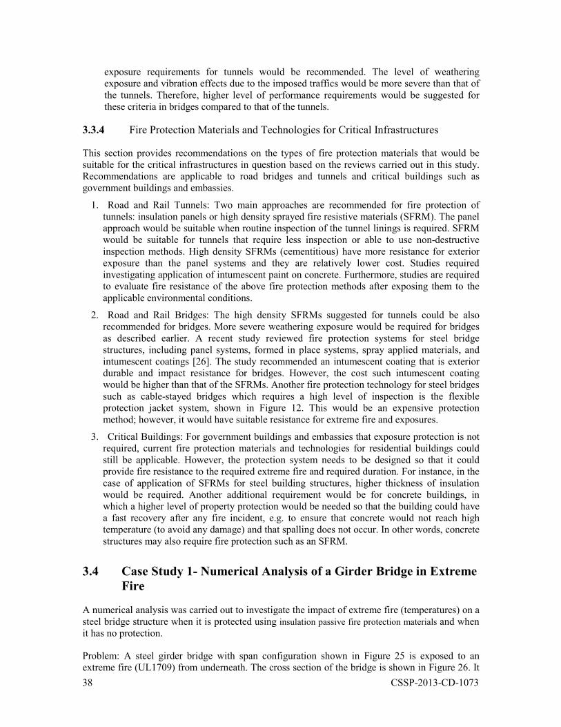
Problem: A steel girder bridge with span configuration shown in Figure 25 is exposed to an extreme fire (UL1709) from underneath. The cross section of the bridge is shown in Figure 26. It
39 CSSP-2013-CD-1073
is assumed that the steel girders consist of a 1372mm× 13 mm steel plate as the web, a 355mm× 22 mm steel plate as the bottom flange, and a 355mm× 16 mm steel plate as the top flange. Thickness of the concrete deck is 203mm. Temperatures in steel and concrete need to be determined when:
no fire protection material is employed and
when a fire protection material, e.g. SFRM, with thermal conductivity of 0.12 W/mK and specific heat 1200 J/kg K is sprayed on both concrete and steel.
Figure 25. A two span steel bridge with a concrete deck (end supports are expansion bearing and middle support is fixed bearing).
Figure 26. Cross section of the bridge.
SAFIR software was used for the purpose of this analysis [28]. Heat transfer numerical modelings were performed for the two scenarios:
Numerical modeling of the bridge with no protection
A finite element model (FEM) was generated for the cross section of the bridge. For simplicity in a conservative approach, the curbs of the bridge are ignored. Figure 27 shows the mesh generated for the cross section of the bridge.
36.58m 36.58m
1.2m 1.2m 3.0m 3.0m 3.0m

40 CSSP-2013-CD-1073
Figure 27. Cross section of the bridge model.
The bridge deck was considered to be made of normal concrete with siliceous aggregates with a 10 kg/m3 moisture content. The bridge surface was exposed from underneath to a UL1709 time-temperature curve [2] for one hour. Figures 28 and 29 show the temperature distribution on the cross section of the bridge at time = 1 hour. The negative temperature shown in the legend is due to the program convergence. More fine mesh could reduce such an error. As it can be seen steel has already reached 1100 degree C, exceeding the failure criteria of 538 degree C [2]. Figure 30 illustrates the temperatures in the steel and concrete (at 25mm depth from the surface) along with the fire curve. The Figure indicates that the bridge steel deck failed in less than 5 minutes exceeding the 538 degree C based on the UL1709 criteria.
Figure 28. Temperature distribution on the cross section with no protection at t=1 hour.
Figure 29. Temperature distribution on the cross section of one girder enlarged from Figure 28.
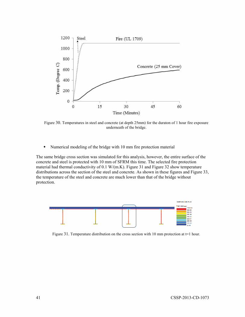
41 CSSP-2013-CD-1073
Figure 30. Temperatures in steel and concrete (at depth 25mm) for the duraton of 1 hour fire exposure underneath of the bridge.
Numerical modeling of the bridge with 10 mm fire protection material
The same bridge cross section was simulated for this analysis, however, the entire surface of the concrete and steel is protected with 10 mm of SFRM this time. The selected fire protection material had thermal conductivity of 0.1 W/(m.K). Figure 31 and Figure 32 show temperature distributions across the section of the steel and concrete. As shown in these figures and Figure 33, the temperature of the steel and concrete are much lower than that of the bridge without protection.
Figure 31. Temperature distribution on the cross section with 10 mm protection at t=1 hour.
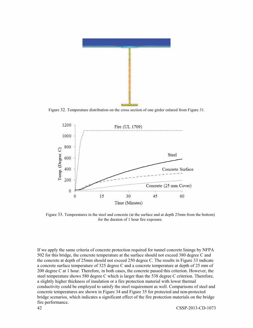
42 CSSP-2013-CD-1073
Figure 32. Temperature distribution on the cross section of one girder enlared from Figure 31.
Figure 33. Temperatures in the steel and concrete (at the surface and at depth 25mm from the bottom) for the duraton of 1 hour fire exposure.
If we apply the same criteria of concrete protection required for tunnel concrete linings by NFPA 502 for this bridge, the concrete temperature at the surface should not exceed 380 degree C and the concrete at depth of 25mm should not exceed 250 degree C. The results in Figure 33 indicate a concrete surface temperature of 325 degree C and a concrete temperature at depth of 25 mm of 200 degree C at 1 hour. Therefore, in both cases, the concrete passed this criterion. However, the steel temperature shows 580 degree C which is larger than the 538 degree C criterion. Therefore, a slightly higher thickness of insulation or a fire protection material with lower thermal conductivity could be employed to satisfy the steel requirement as well. Comparisons of steel and concrete temperatures are shown in Figure 34 and Figure 35 for protected and non-protected bridge scenarios, which indicates a significant effect of the fire protection materials on the bridge fire performance.
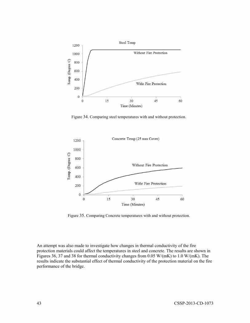
43 CSSP-2013-CD-1073
Figure 34. Comparing steel temperatures with and without protection.
Figure 35. Comparing Concrete temperatures with and without protection.
An attempt was also made to investigate how changes in thermal conductivity of the fire protection materials could affect the temperatures in steel and concrete. The results are shown in Figures 36, 37 and 38 for thermal conductivity changes from 0.05 W/(mK) to 1.0 W/(mK). The results indicate the substantial effect of thermal conductivity of the protection material on the fire performance of the bridge.
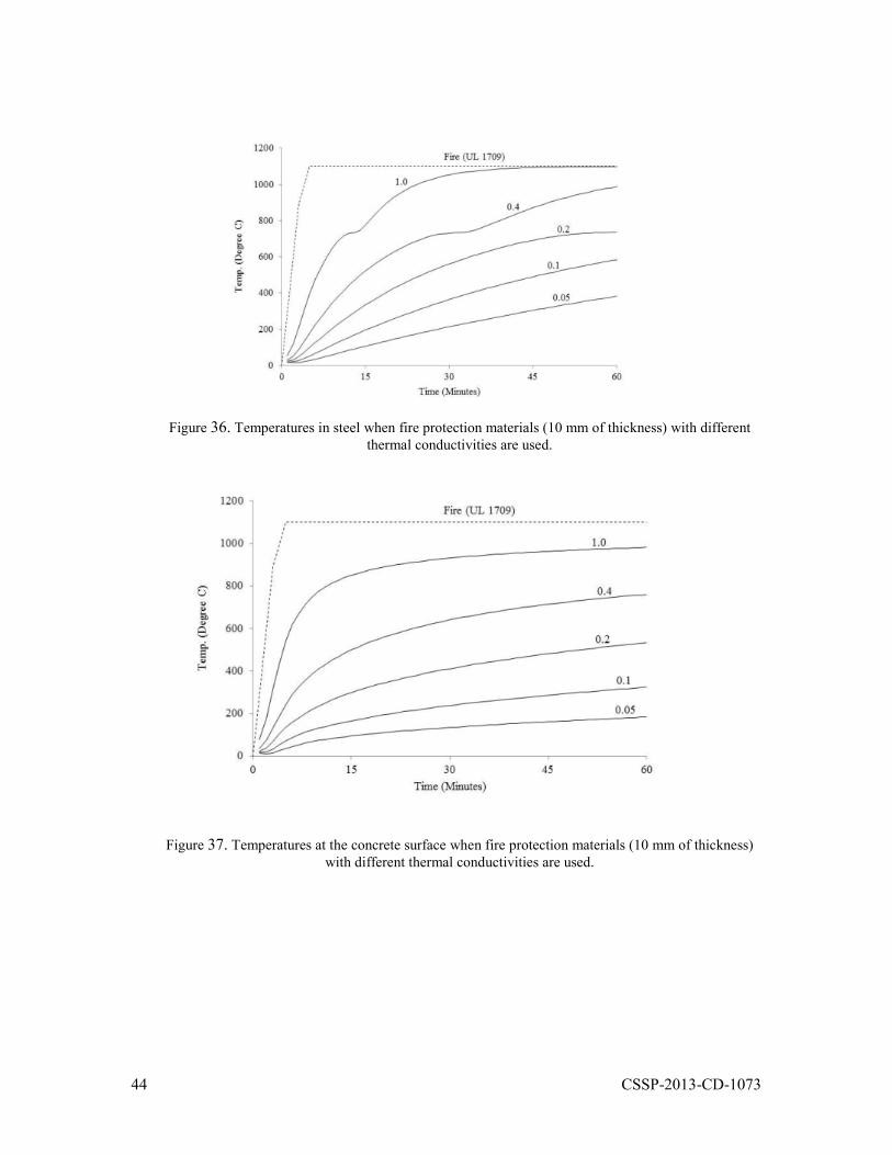
44 CSSP-2013-CD-1073
Figure 36. Temperatures in steel when fire protection materials (10 mm of thickness) with different thermal conductivities are used.
Figure 37. Temperatures at the concrete surface when fire protection materials (10 mm of thickness) with different thermal conductivities are used.
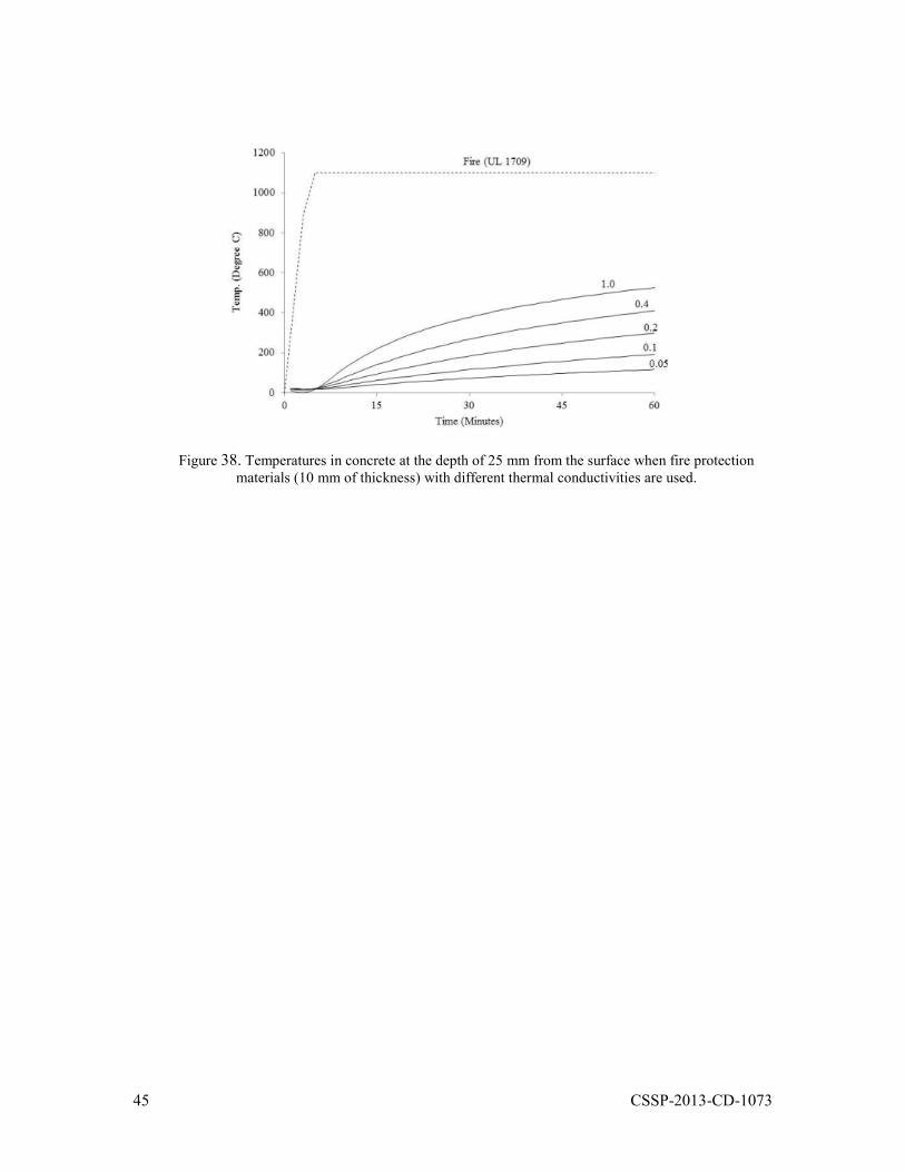
45 CSSP-2013-CD-1073
Figure 38. Temperatures in concrete at the depth of 25 mm from the surface when fire protection materials (10 mm of thickness) with different thermal conductivities are used.
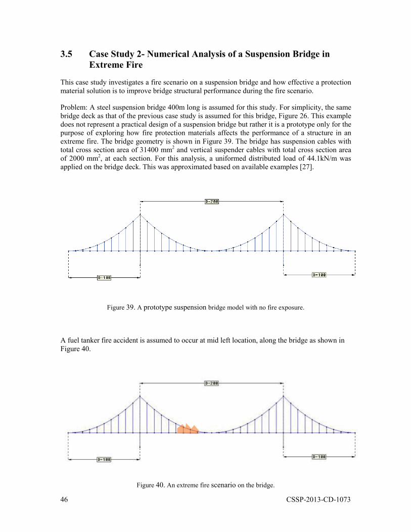
46 CSSP-2013-CD-1073
3.5 Case Study 2- Numerical Analysis of a Suspension Bridge in Extreme Fire
This case study investigates a fire scenario on a suspension bridge and how effective a protection material solution is to improve bridge structural performance during the fire scenario.
Problem: A steel suspension bridge 400m long is assumed for this study. For simplicity, the same bridge deck as that of the previous case study is assumed for this bridge, Figure 26. This example does not represent a practical design of a suspension bridge but rather it is a prototype only for the purpose of exploring how fire protection materials affects the performance of a structure in an extreme fire. The bridge geometry is shown in Figure 39. The bridge has suspension cables with total cross section area of 31400 mm2 and vertical suspender cables with total cross section area of 2000 mm2, at each section. For this analysis, a uniformed distributed load of 44.1kN/m was applied on the bridge deck. This was approximated based on available examples [27].
Figure 39. A prototype suspension bridge model with no fire exposure.
A fuel tanker fire accident is assumed to occur at mid left location, along the bridge as shown in Figure 40.
Figure 40. An extreme fire scenario on the bridge.
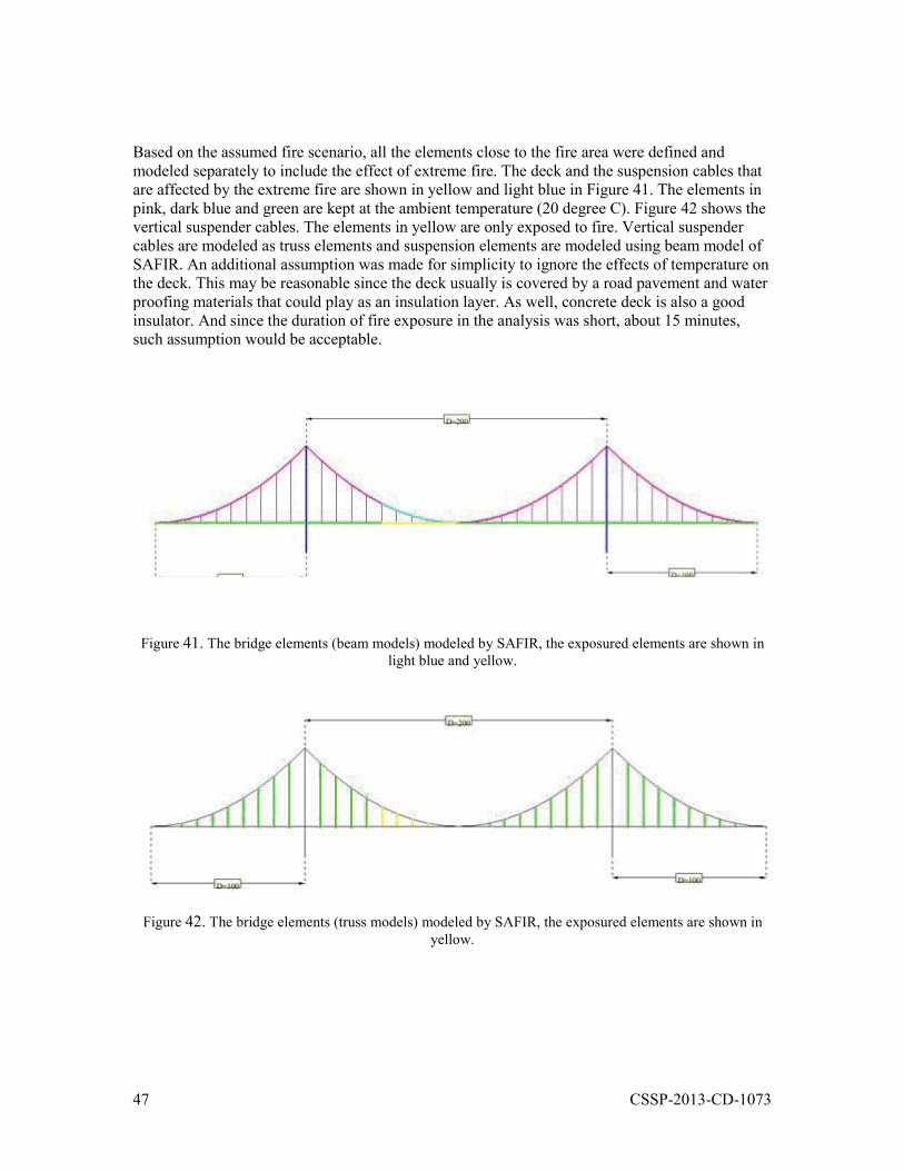
47 CSSP-2013-CD-1073
Based on the assumed fire scenario, all the elements close to the fire area were defined and modeled separately to include the effect of extreme fire. The deck and the suspension cables that are affected by the extreme fire are shown in yellow and light blue in Figure 41. The elements in pink, dark blue and green are kept at the ambient temperature (20 degree C). Figure 42 shows the vertical suspender cables. The elements in yellow are only exposed to fire. Vertical suspender cables are modeled as truss elements and suspension elements are modeled using beam model of SAFIR. An additional assumption was made for simplicity to ignore the effects of temperature on the deck. This may be reasonable since the deck usually is covered by a road pavement and water proofing materials that could play as an insulation layer. As well, concrete deck is also a good insulator. And since the duration of fire exposure in the analysis was short, about 15 minutes, such assumption would be acceptable.
Figure 41. The bridge elements (beam models) modeled by SAFIR, the exposured elements are shown in light blue and yellow.
Figure 42. The bridge elements (truss models) modeled by SAFIR, the exposured elements are shown in yellow.
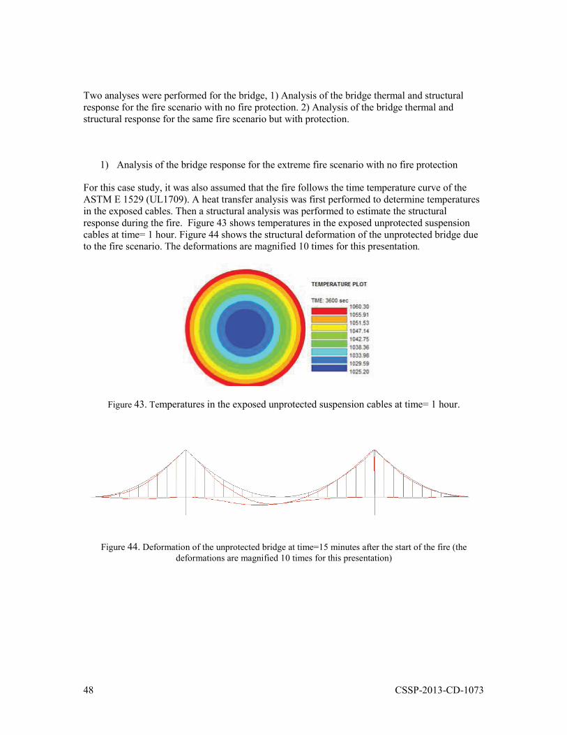
48 CSSP-2013-CD-1073
Two analyses were performed for the bridge, 1) Analysis of the bridge thermal and structural response for the fire scenario with no fire protection. 2) Analysis of the bridge thermal and structural response for the same fire scenario but with protection.
1) Analysis of the bridge response for the extreme fire scenario with no fire protection
For this case study, it was also assumed that the fire follows the time temperature curve of the ASTM E 1529 (UL1709). A heat transfer analysis was first performed to determine temperatures in the exposed cables. Then a structural analysis was performed to estimate the structural response during the fire. Figure 43 shows temperatures in the exposed unprotected suspension cables at time= 1 hour. Figure 44 shows the structural deformation of the unprotected bridge due to the fire scenario. The deformations are magnified 10 times for this presentation.
Figure 43. Temperatures in the exposed unprotected suspension cables at time= 1 hour.
Figure 44. Deformation of the unprotected bridge at time=15 minutes after the start of the fire (the deformations are magnified 10 times for this presentation)
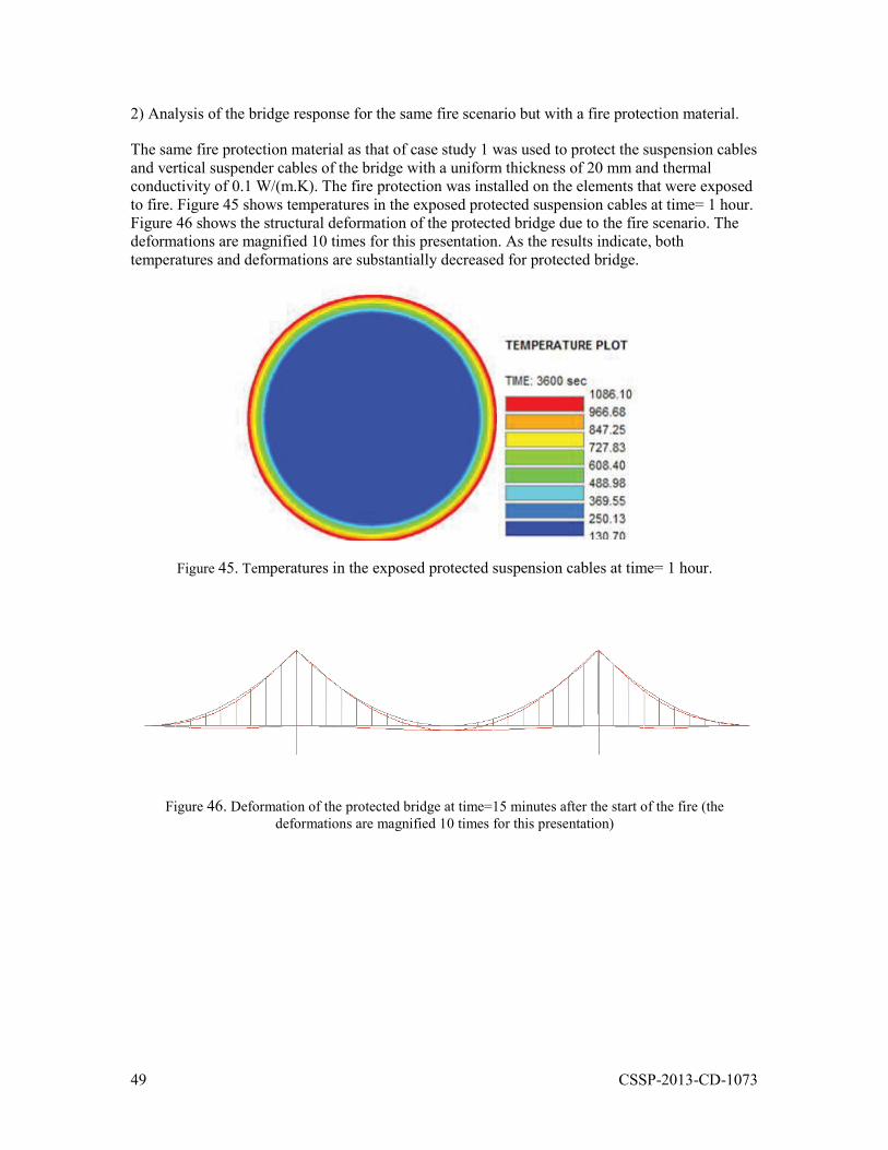
49 CSSP-2013-CD-1073
2) Analysis of the bridge response for the same fire scenario but with a fire protection material.
The same fire protection material as that of case study 1 was used to protect the suspension cables and vertical suspender cables of the bridge with a uniform thickness of 20 mm and thermal conductivity of 0.1 W/(m.K). The fire protection was installed on the elements that were exposed to fire. Figure 45 shows temperatures in the exposed protected suspension cables at time= 1 hour. Figure 46 shows the structural deformation of the protected bridge due to the fire scenario. The deformations are magnified 10 times for this presentation. As the results indicate, both temperatures and deformations are substantially decreased for protected bridge.
Figure 45. Temperatures in the exposed protected suspension cables at time= 1 hour.
Figure 46. Deformation of the protected bridge at time=15 minutes after the start of the fire (the deformations are magnified 10 times for this presentation)
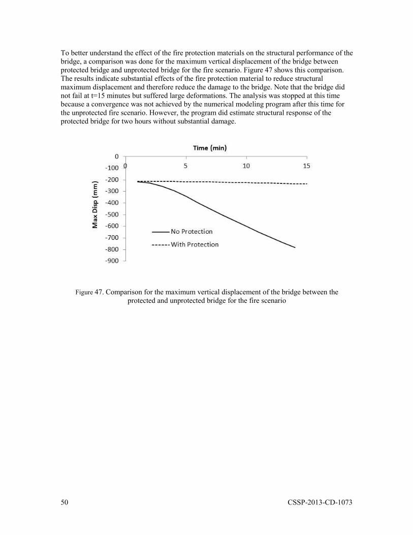
50 CSSP-2013-CD-1073
To better understand the effect of the fire protection materials on the structural performance of the bridge, a comparison was done for the maximum vertical displacement of the bridge between protected bridge and unprotected bridge for the fire scenario. Figure 47 shows this comparison. The results indicate substantial effects of the fire protection material to reduce structural maximum displacement and therefore reduce the damage to the bridge. Note that the bridge did not fail at t=15 minutes but suffered large deformations. The analysis was stopped at this time because a convergence was not achieved by the numerical modeling program after this time for the unprotected fire scenario. However, the program did estimate structural response of the protected bridge for two hours without substantial damage.
Figure 47. Comparison for the maximum vertical displacement of the bridge between the protected and unprotected bridge for the fire scenario
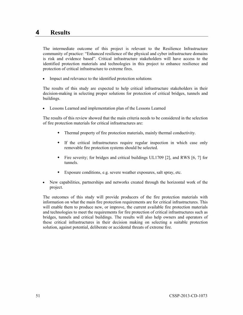
51 CSSP-2013-CD-1073
4 Results
The intermediate outcome of this project is relevant to the Resilience Infrastructure community of practice: “Enhanced resilience of the physical and cyber infrastructure domains is risk and evidence based”. Critical infrastructure stakeholders will have access to the identified protection materials and technologies in this project to enhance resilience and protection of critical infrastructure to extreme fires.
Impact and relevance to the identified protection solutions
The results of this study are expected to help critical infrastructure stakeholders in their decision-making in selecting proper solutions for protection of critical bridges, tunnels and buildings.
Lessons Learned and implementation plan of the Lessons Learned
The results of this review showed that the main criteria needs to be considered in the selection of fire protection materials for critical infrastructures are:
Thermal property of fire protection materials, mainly thermal conductivity.
If the critical infrastructures require regular inspection in which case only removable fire protection systems should be selected.
Fire severity; for bridges and critical buildings UL1709 [2], and RWS [6, 7] for tunnels.
Exposure conditions, e.g. severe weather exposures, salt spray, etc.
New capabilities, partnerships and networks created through the horizontal work of the project.
The outcomes of this study will provide producers of the fire protection materials with information on what the main fire protection requirements are for critical infrastructures. This will enable them to produce new, or improve, the current available fire protection materials and technologies to meet the requirements for fire protection of critical infrastructures such as bridges, tunnels and critical buildings. The results will also help owners and operators of these critical infrastructures in their decision making on selecting a suitable protection solution, against potential, deliberate or accidental threats of extreme fire.
52 CSSP-2013-CD-1073
5 Transition and Exploitation
Transition to End Users: The end users of the outcome of this project are transportation infrastructures, government buildings and facilities, regulatory bodies, and construction industries. The results of this study will be shared with these stakeholders through webinars, conferences and publications. At least one paper will be produced from the outcome of this study and will be presented in a related conference. Finally, this report will be shared with the end users through DRDC.
Follow-On Commercial Development or R&D Recommended: NRC will take the results of this study to the next level. This will be done through a new R&D with the fire protection material industries. The goal will be to test the main identified fire protection materials to assess if their fire performance will meet the required performance levels for different types of critical infrastructures as described in this report. This R&D will be at the demonstration level.
Intellectual Property Disposition:
The IP produced by this study vests in the Crown.
Public Information Recommendations:
The recommendations produced by this study are intended to be used by the end users.
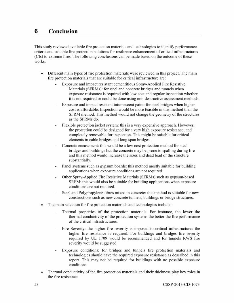
53 CSSP-2013-CD-1073
6 Conclusion
This study reviewed available fire protection materials and technologies to identify performance criteria and suitable fire protection solutions for resilience enhancement of critical infrastructures (CIs) to extreme fires. The following conclusions can be made based on the outcome of these works.
Different main types of fire protection materials were reviewed in this project. The main fire protection materials that are suitable for critical infrastructure are:
- Exposure and impact resistant cementitious Spray-Applied Fire Resistive Materials (SFRMs): for steel and concrete bridges and tunnels when exposure resistance is required with low cost and regular inspection whether it is not required or could be done using non-destructive assessment methods.
- Exposure and impact resistant intumescent paint: for steel bridges when higher cost is affordable. Inspection would be more feasible in this method than the SFRM method. This method would not change the geometry of the structures as the SFRMs do.
- Flexible protection jacket system: this is a very expensive approach. However, the protection could be designed for a very high exposure resistance, and completely removable for inspection. This might be suitable for critical elements in cable bridges and long span bridges.
- Concrete encasement: this would be a low cost protection method for steel bridges and buildings but the concrete may be prone to spalling during fire and this method would increase the sizes and dead load of the structure substantially.
- Panel systems such as gypsum boards: this method mostly suitable for building applications when exposure conditions are not required.
- Other Spray-Applied Fire Resistive Materials (SFRMs) such as gypsum-based SRFM: this would also be suitable for building applications when exposure conditions are not required.
- Steel and Polypropylene fibres mixed in concrete: this method is suitable for new constructions such as new concrete tunnels, buildings or bridge structures.
The main selection for fire protection materials and technologies include:
- Thermal properties of the protection materials. For instance, the lower the thermal conductivity of the protection systems the better the fire performance of the critical infrastructures.
- Fire Severity: the higher fire severity is imposed to critical infrastructures the higher fire resistance is required. For buildings and bridges fire severity required by UL 1709 would be recommended and for tunnels RWS fire severity would be suggested.
- Exposure conditions: for bridges and tunnels fire protection materials and technologies should have the required exposure resistance as described in this report. This may not be required for buildings with no possible exposure conditions.
Thermal conductivity of the fire protection materials and their thickness play key roles in the fire resistance.
54 CSSP-2013-CD-1073
References.
[1] Mostafaei, H., Cowalchuk, R., Kashef, A., Sultan, M., McCartney, C., and Leroux, P. (2013). “Resilience of Critical Infrastructure to Extreme Fires – Gaps and Challenges”, NRC_CSSP Research Report, pp. 74.
[2] CAN/ULC-S101 (2008). "Fire Endurance Tests of Building Construction and Materials", Underwriters' Laboratories of Canada, Scarborough, ON.
[3] UL 263 (2014). “Standard for Fire Tests of Building Construction and Materials", Underwriters' Laboratories, Northbrook, Illinois.
[4] UL 1709 (2011). Rapid Rise Fire Tests of Protection Materials for Structural Steel, UL.
[5] ASTM E1529 (2010). Standard Test Methods for Determining Effects of Large Hydrocarbon Pool Fires on Structural Members and Assemblies.
[6] NFPA 502 (2011). "Standard for Road Tunnels, Bridges, and Other Limited Access Highways", National Fire Protection Association, pp. 51.
[7] Breunese, A.J., Both, C., Wolsink, G.M. (2008). "Fire testing procedure for concrete tunnel linings", Efectis-R0695, pp. 25.
[8] Wright, W., Lattimer, B., Woodworth, M., Nahid, M., and Sotelino, E. (2013). “Highway Bridge Fire Hazard Assessment Draft Final Report, Prepared for the NCHRP Program Transportation Research Board of The National Academies, Virginia Polytechnic Institute and State University, pp. 492.
[9] Mostafaei, H. and McCartney, C. (2012). "Vulnerability of Bridges and other Critical Transportation Infrastructure to Extreme Fire and BLEVEs", NRC Research Report No. 4259, pp. 68.
[10] Beard, A., Carvel R. "The handbook of tunnel fire safety", Thomas Telford, 2005, p. 514.
[11] Canadian Commission on Building and Fire Codes (2010). "National Building Code of Canada" National Research Council Canada.
[12] Michael G. Goode, Editor, “Fire Protection of Structural Steel in High-Rise Buildings”, Building and Fire Research Laboratory, National Institute of Standards and Technology, July 2004, pp. 88.
[13] Kodur, V.K.R. “Fire Resistance of Concrete-Filled Steel Columns”, NRC Construction Innovation No. 6, 1997.
[14] Lie, T.T., Kodur, V.R. “Thermal and mechanical properties of steel-fibre-reinforced concrete at elevated temperatures”, Canadian Journal of Civil Engineering, 23, (4), pp. 511-517, April 01, 1996.
[15] Kodur, V.R. “Fiber Reinforced Concrete for Enhancing Structural Fire Resistance of Columns”, ACI Spring Convention, Seattle, WA, 1997.
[16] Alan Richardson, Urmil V. Dave. "The effect of polypropylene fibres within concrete with regard to fire performance in structures", Structural Survey, Vol. 26 Iss: 5, pp.435 – 444, 2008.
[17] Chris Miles. “Approval of Structural Steel Protection Materials for Hydrocarbon Fires”, A presentation posted at http://wto.wtcmoscow.ru/common/upload/PresentationARF/Cris_Miles.pdf, UL Europe & Latin America, latest access Feb 2014, pp. 29.
55 CSSP-2013-CD-1073
[18] Buchanan, A.H. Structural Design for Fire Safety, John Wiley & Sons, LTD., 2002.
[19] Bentz, D.P., Prasad, K.R.”Thermal Performance of Fire Resistive Materials I. Characterization with Respect to Thermal Performance Models”, NISTIR 7401, National Institute of Standards and Technology, pp. 29.
[20] UL 2431. “Standard for Durability of Spray-Applied Fire Resistive Materials”, UL.
[21] ISO 4628-8. “Paints and varnishes -- Evaluation of degradation of coatings -- Designation of quantity and size of defects, and of intensity of uniform changes in appearance -- Part 8: Assessment of degree of delamination and corrosion around a scribe or other artificial defect”, ISO 2012.
[22] ASTM B117 – 11. Standard Practice for Operating Salt Spray (Fog) Apparatus, ASTM, 2011.
[23] ISO 7253. “Paints and varnishes -- Determination of resistance to neutral salt spray (fog)”,ISO, 1996.
[24] ISO 2812-2. “Paints and varnishes -- Determination of resistance to liquids -- Part 2: Water immersion method”, ISO, 2007.
[25] ISO 20340. “Paints and varnishes -- Performance requirements for protective paint systems for offshore and related structures”, ISO, 2009.
[26] Greigger, P.P., Parker, A.J., Wheeler, W.P. “Fire Protection of Steel Bridges”, A presentation posted by Hughes Associates, www.haifire.com, last accessed Feb 2014.
[27] Example (accessed Feb 2014). “LRFD Steel Girder SuperStructure Design Example, Steel Girder Design Example Design Step 3”, Bridge and Structures, Federal Highway Administration U.S. Department of Transportation, www.fhwa.dot.gov/bridge.
[28] User Manual for SAFIR. A Computer Program for Analysis of Structures at Elevated Temperature Conditions, D. I. Nwosu, V. K. R. Kodur, J.-M. Franssen & J. K. Hum, National Research Council Canada, int. Report 782 (1999), pp 69.
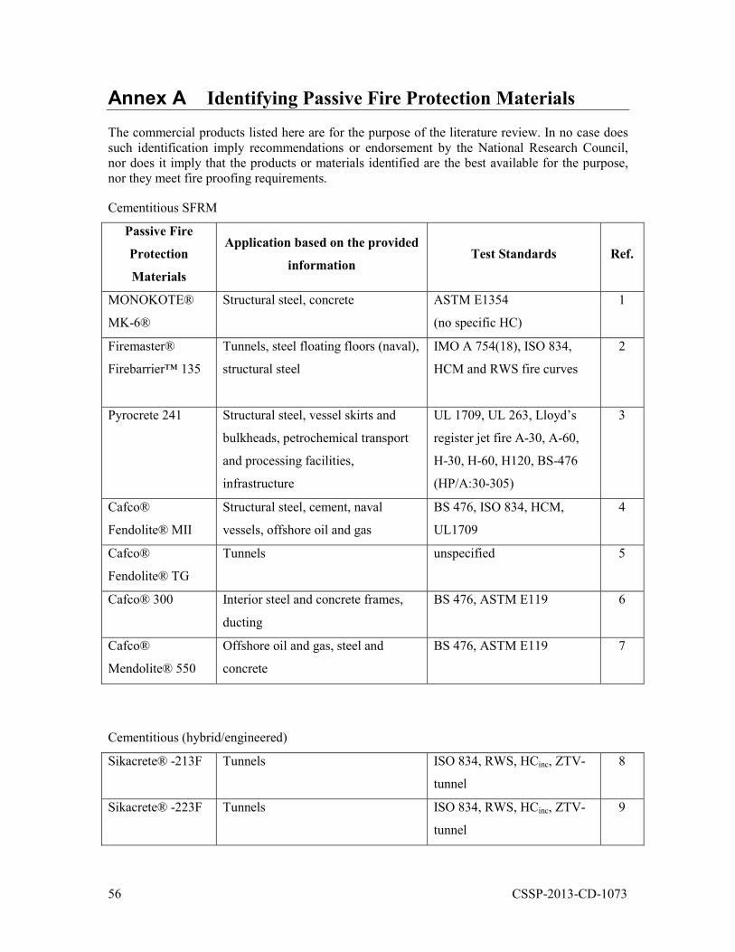
56 CSSP-2013-CD-1073
Annex A Identifying Passive Fire Protection Materials
The commercial products listed here are for the purpose of the literature review. In no case does such identification imply recommendations or endorsement by the National Research Council, nor does it imply that the products or materials identified are the best available for the purpose, nor they meet fire proofing requirements.
Cementitious SFRM
Passive Fire
Protection
Materials
Application based on the provided
information Test Standards Ref.
MONOKOTE®
MK-6®
Structural steel, concrete ASTM E1354
(no specific HC)
1
Firemaster®
Firebarrier™ 135
Tunnels, steel floating floors (naval),
structural steel
IMO A 754(18), ISO 834,
HCM and RWS fire curves
2
Pyrocrete 241 Structural steel, vessel skirts and
bulkheads, petrochemical transport
and processing facilities,
infrastructure
UL 1709, UL 263, Lloyd’s
register jet fire A-30, A-60,
H-30, H-60, H120, BS-476
(HP/A:30-305)
3
Cafco®
Fendolite® MII
Structural steel, cement, naval
vessels, offshore oil and gas
BS 476, ISO 834, HCM,
UL1709
4
Cafco®
Fendolite® TG
Tunnels unspecified 5
Cafco® 300 Interior steel and concrete frames,
ducting
BS 476, ASTM E119 6
Cafco®
Mendolite® 550
Offshore oil and gas, steel and
concrete
BS 476, ASTM E119 7
Cementitious (hybrid/engineered)
Sikacrete® -213F Tunnels ISO 834, RWS, HCinc, ZTV-
tunnel
8
Sikacrete® -223F Tunnels ISO 834, RWS, HCinc, ZTV-
tunnel
9
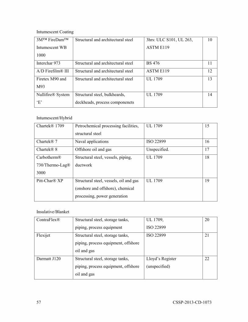
57 CSSP-2013-CD-1073
Intumescent Coating
3M™ FireDam™
Intumescent WB
1000
Structural and architectural steel 3hrs: ULC S101, UL 263,
ASTM E119
10
Interchar 973 Structural and architectural steel BS 476 11
A/D Firefilm® III Structural and architectural steel ASTM E119 12
Firetex M90 and
M93
Structural and architectural steel UL 1709 13
Nullifire® System
‘E’
Structural steel, bulkheards,
deckheads, process componenets
UL 1709 14
Intumescent/Hybrid
Chartek® 1709 Petrochemical processing facilities,
structural steel
UL 1709 15
Chartek® 7 Naval applications ISO 22899 16
Chartek® 8 Offshore oil and gas Unspecified. 17
Carbotherm®
730/Thermo-Lag®
3000
Structural steel, vessels, piping,
ductwork
UL 1709 18
Pitt-Char® XP Structural steel, vessels, oil and gas
(onshore and offshore), chemical
processing, power generation
UL 1709 19
Insulative/Blanket
ContraFlex® Structural steel, storage tanks,
piping, process equipment
UL 1709,
ISO 22899
20
Flexijet Structural steel, storage tanks,
piping, process equipment, offshore
oil and gas
ISO 22899 21
Darmatt J120 Structural steel, storage tanks,
piping, process equipment, offshore
oil and gas
Lloyd’s Register
(unspecified)
22
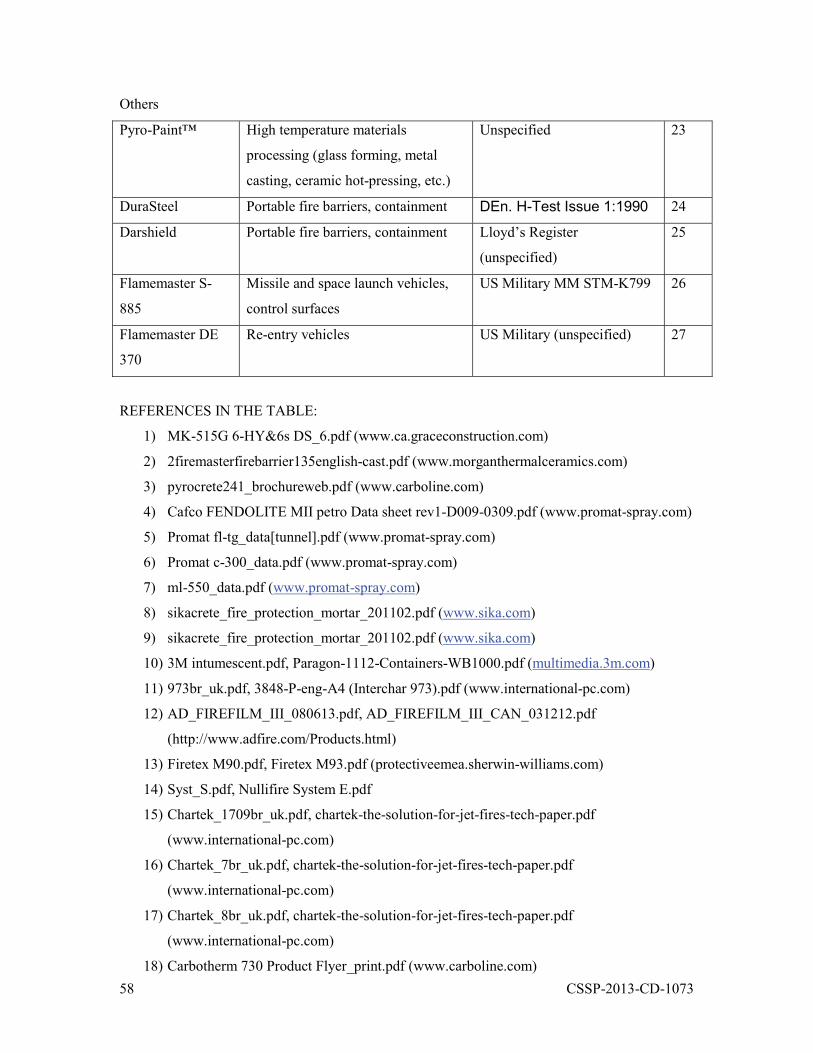
58 CSSP-2013-CD-1073
Others
Pyro-Paint™ High temperature materials
processing (glass forming, metal
casting, ceramic hot-pressing, etc.)
Unspecified 23
DuraSteel Portable fire barriers, containment DEn. H-Test Issue 1:1990 24
Darshield Portable fire barriers, containment Lloyd’s Register
(unspecified)
25
Flamemaster S-
885
Missile and space launch vehicles,
control surfaces
US Military MM STM-K799 26
Flamemaster DE
370
Re-entry vehicles US Military (unspecified) 27
REFERENCES IN THE TABLE:
1) MK-515G 6-HY&6s DS_6.pdf (www.ca.graceconstruction.com)
2) 2firemasterfirebarrier135english-cast.pdf (www.morganthermalceramics.com)
3) pyrocrete241_brochureweb.pdf (www.carboline.com)
4) Cafco FENDOLITE MII petro Data sheet rev1-D009-0309.pdf (www.promat-spray.com)
5) Promat fl-tg_data[tunnel].pdf (www.promat-spray.com)
6) Promat c-300_data.pdf (www.promat-spray.com)
7) ml-550_data.pdf (www.promat-spray.com)
8) sikacrete_fire_protection_mortar_201102.pdf (www.sika.com)
9) sikacrete_fire_protection_mortar_201102.pdf (www.sika.com)
10) 3M intumescent.pdf, Paragon-1112-Containers-WB1000.pdf (multimedia.3m.com)
11) 973br_uk.pdf, 3848-P-eng-A4 (Interchar 973).pdf (www.international-pc.com)
12) AD_FIREFILM_III_080613.pdf, AD_FIREFILM_III_CAN_031212.pdf
(http://www.adfire.com/Products.html)
13) Firetex M90.pdf, Firetex M93.pdf (protectiveemea.sherwin-williams.com)
14) Syst_S.pdf, Nullifire System E.pdf
15) Chartek_1709br_uk.pdf, chartek-the-solution-for-jet-fires-tech-paper.pdf
(www.international-pc.com)
16) Chartek_7br_uk.pdf, chartek-the-solution-for-jet-fires-tech-paper.pdf
(www.international-pc.com)
17) Chartek_8br_uk.pdf, chartek-the-solution-for-jet-fires-tech-paper.pdf
(www.international-pc.com)
18) Carbotherm 730 Product Flyer_print.pdf (www.carboline.com)

59 CSSP-2013-CD-1073
19) Ppg_fire_protection_brochure_20jul2011.pdf, ppg-pitt-char-xp-product-brochure-
a4_26jun2012_en_lrsp.pdf, pittchar_cepsa_case_study_a4.pdf, pitt-
char_xp_half_platform_ primetime_protective_final.pdf, msds pitt-char xp ep 97-194
component a (eng) (sk-01-06-10leg-mt).pdf (www.ppg.com)
20) Advanced Insulation ContraFlex 16 07 2012.pdf (www.aisplc.com)
21) flexijet_brochure.pdf (www.kemwellthermal.com)
22) DTP_Brochure.pdf (www.darchem.co.uk)
23) A05_S5_12_Refractory.pdf (www.aremco.com/high-temp-refractory-coatings/)
24) Enclosures Brochure.pdf (www.durasystems.com)
25) DTP_Brochure.pdf (www.darchem.co.uk)
26) s885reva.pdf (www.flamemaster.com)
27) DE370 june-2020.pdf (www.flamemaster.com)
60 CSSP-2013-CD-1073
Annex B Project Team
Pierre Meunier, Head, Border and Critical Infrastructure Resilience, S&T, Defence R&D Canada- Centre for Security Science, was the Cluster/CoP lead of this project and contributed greatly in the development and implementation of the research plan. Dr Darek Bingo was the researcher representative from S&T, Defence R&D Canada- Centre for Security Science in this study.
Hossein Mostafaei, PhD, P.Eng., a Research Officer of the Fire Safety, the National Research Council Canada who managed this project.
NRC Research team included:
Ahmed Kashef, Director, Fire Safety, National Research Council Canada
Mohamed Sultan, Senior Research Officer, Fire Safety, National Research Council Canada
Dave Edwards, Technical Officer, Fire Safety, National Research Council Canada
61 CSSP-2013-CD-1073
Annex C Project Performance Summary
PROJECT PERFORMANCE SUMMARY Technical Performance Summary: The main objective of this project was to review the available of fire protection materials and to identify potential technologies, e.g. materials or systems, for protection of Critical Infrastructures against extreme fires. This objective was fully achieved. Different available protection materials and technologies were reviewed. Criteria for the selection of fire protection materials were established and provided. Based on the reviewed material and technologies and the selection criteria, potential fire protection materials for critical infrastructures were recommended. Two case studies were also carried out to investigate the effect of selecting fire protection materials on the fire performance of the critical infrastructures.
Technology Readiness Level of Deliverable (TRL)
A TRL of 4 could be assigned from the outcome of this project. The concept and process of fire protection methods for the critical infrastructures were established based on the available data that have been validated in a laboratory environment.
Estimated Time to Reach TRL7 Maturity (months)
Studies could be continued for a 24 to 36 months period through which different available fire protection materials could be tested. The results would demonstrate practical methods for enhancing resilience of CIs to extreme fires.
Advantages Over Existing/Competing Technologies
To date, no standard and limited information was available on how to protect critical infrastructures such as bridges to extreme fire. This project provided such information, particularly for resilience enhancement of the critical infrastructures to deliberate or accidental extreme fire threats. Schedule Performance Summary: No time delay was experienced for this project. All tasks were completed as planned in the schedule. Cost Performance Summary: The budget for this project was managed according to the assigned cost estimate. The estimated in-kind contributions were also achieved.

62 CSSP-2013-CD-1073
Annex D Publications, Presentations, Patents
This project includes the following productions:
The present research report. Publications and presentations will be delivered at the conferences and workshops in 2014.

63 CSSP-2013-CD-1073
List of symbols/abbreviations/acronyms/initialisms
CI Critical Infrastructure DRDC Defence Research & Development Canada
NFPA National Fire Protection Association NRC National Research Council Canada R&D Research & Development
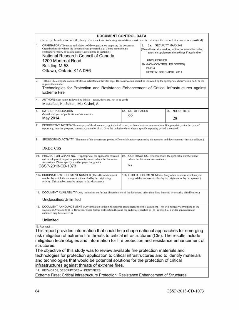
64 CSSP-2013-CD-1073
DOCUMENT CONTROL DATA
(Security classification of title, body of abstract and indexing annotation must be entered when the overall document is classified) 1. ORIGINATOR (The name and address of the organization preparing the document.
Organizations for whom the document was prepared, e.g. Centre sponsoring a contractor's report, or tasking agency, are entered in section 8.)
National Research Council of Canada 1200 Montreal Road Building M-58 Ottawa, Ontario K1A 0R6
2. 2a. SECURITY MARKING (Overall security marking of the document including
special supplemental markings if applicable.) UNCLASSIFIED 2b. (NON-CONTROLLED GOODS) DMC A REVIEW: GCEC APRIL 2011
3. TITLE (The complete document title as indicated on the title page. Its classification should be indicated by the appropriate abbreviation (S, C or U)
in parentheses after Technologies for Protection and Resistance Enhancement of Critical Infrastructures against Extreme Fire
4. AUTHORS (last name, followed by initials – ranks, titles, etc. not to be used) Mostafaei, H.; Sultan, M.; Kashef, A.
5. DATE OF PUBLICATION (Month and year of publication of document.) May 2014
6a. NO. OF PAGES
6 6b. NO. OF REFS
28 7. DESCRIPTIVE NOTES (The category of the document, e.g. technical report, technical note or memorandum. If appropriate, enter the type of
report, e.g. interim, progress, summary, annual or final. Give the inclusive dates when a specific reporting period is covered.)
8. SPONSORING ACTIVITY (The name of the department project office or laboratory sponsoring the research and development – include address.)
DRDC CSS
9a. PROJECT OR GRANT NO. (If appropriate, the applicable research and development project or grant number under which the document was written. Please specify whether project or grant.)
CSSP-2013-CD-1073
9b. CONTRACT NO. (If appropriate, the applicable number under which the document was written.)
NA
10a. ORIGINATOR'S DOCUMENT NUMBER (The official document number by which the document is identified by the originating activity. This number must be unique to this document.)
10b. OTHER DOCUMENT NO(s). (Any other numbers which may be assigned this document either by the originator or by the sponsor.)
11. DOCUMENT AVAILABILITY (Any limitations on further dissemination of the document, other than those imposed by security classification.)
Unclassified/Unlimited
12. DOCUMENT ANNOUNCEMENT (Any limitation to the bibliographic announcement of this document. This will normally correspond to the Document Availability (11). However, where further distribution (beyond the audience specified in (11) is possible, a wider announcement audience may be selected.)) Unlimited
13. Abstract … This report provides information that could help shape national approaches for emerging risk mitigation of extreme fire threats to critical infrastructures (CIs). The results include mitigation technologies and information for fire protection and resistance enhancement of structures. The objective of this study was to review available fire protection materials and technologies for protection application to critical infrastructures and to identify materials and technologies that would be potential solutions for the protection of critical infrastructures against threats of extreme fires. 14. KEYWORDS, DESCRIPTORS or IDENTIFIERS Extreme Fires; Critical Infrastructure Protection; Resistance Enhancement of Structures